JP2023515085A - colonoscopy control system - Google Patents
colonoscopy control systemDownload PDFInfo
- Publication number
- JP2023515085A JP2023515085AJP2022549937AJP2022549937AJP2023515085AJP 2023515085 AJP2023515085 AJP 2023515085AJP 2022549937 AJP2022549937 AJP 2022549937AJP 2022549937 AJP2022549937 AJP 2022549937AJP 2023515085 AJP2023515085 AJP 2023515085A
- Authority
- JP
- Japan
- Prior art keywords
- shaft
- interface
- drive unit
- colonoscope
- control system
- Prior art date
- Legal status (The legal status is an assumption and is not a legal conclusion. Google has not performed a legal analysis and makes no representation as to the accuracy of the status listed.)
- Pending
Links
Images


Classifications
- A—HUMAN NECESSITIES
- A61—MEDICAL OR VETERINARY SCIENCE; HYGIENE
- A61B—DIAGNOSIS; SURGERY; IDENTIFICATION
- A61B1/00—Instruments for performing medical examinations of the interior of cavities or tubes of the body by visual or photographical inspection, e.g. endoscopes; Illuminating arrangements therefor
- A61B1/005—Flexible endoscopes
- A61B1/0051—Flexible endoscopes with controlled bending of insertion part
- A61B1/0052—Constructional details of control elements, e.g. handles
- A—HUMAN NECESSITIES
- A61—MEDICAL OR VETERINARY SCIENCE; HYGIENE
- A61B—DIAGNOSIS; SURGERY; IDENTIFICATION
- A61B1/00—Instruments for performing medical examinations of the interior of cavities or tubes of the body by visual or photographical inspection, e.g. endoscopes; Illuminating arrangements therefor
- A61B1/00002—Operational features of endoscopes
- A61B1/00039—Operational features of endoscopes provided with input arrangements for the user
- A61B1/00042—Operational features of endoscopes provided with input arrangements for the user for mechanical operation
- A—HUMAN NECESSITIES
- A61—MEDICAL OR VETERINARY SCIENCE; HYGIENE
- A61B—DIAGNOSIS; SURGERY; IDENTIFICATION
- A61B1/00—Instruments for performing medical examinations of the interior of cavities or tubes of the body by visual or photographical inspection, e.g. endoscopes; Illuminating arrangements therefor
- A61B1/00112—Connection or coupling means
- A61B1/00121—Connectors, fasteners and adapters, e.g. on the endoscope handle
- A61B1/00128—Connectors, fasteners and adapters, e.g. on the endoscope handle mechanical, e.g. for tubes or pipes
- A—HUMAN NECESSITIES
- A61—MEDICAL OR VETERINARY SCIENCE; HYGIENE
- A61B—DIAGNOSIS; SURGERY; IDENTIFICATION
- A61B1/00—Instruments for performing medical examinations of the interior of cavities or tubes of the body by visual or photographical inspection, e.g. endoscopes; Illuminating arrangements therefor
- A61B1/00131—Accessories for endoscopes
- A61B1/00133—Drive units for endoscopic tools inserted through or with the endoscope
- A—HUMAN NECESSITIES
- A61—MEDICAL OR VETERINARY SCIENCE; HYGIENE
- A61B—DIAGNOSIS; SURGERY; IDENTIFICATION
- A61B1/00—Instruments for performing medical examinations of the interior of cavities or tubes of the body by visual or photographical inspection, e.g. endoscopes; Illuminating arrangements therefor
- A61B1/00147—Holding or positioning arrangements
- A61B1/00149—Holding or positioning arrangements using articulated arms
- A—HUMAN NECESSITIES
- A61—MEDICAL OR VETERINARY SCIENCE; HYGIENE
- A61B—DIAGNOSIS; SURGERY; IDENTIFICATION
- A61B1/00—Instruments for performing medical examinations of the interior of cavities or tubes of the body by visual or photographical inspection, e.g. endoscopes; Illuminating arrangements therefor
- A61B1/00147—Holding or positioning arrangements
- A61B1/0016—Holding or positioning arrangements using motor drive units
- A—HUMAN NECESSITIES
- A61—MEDICAL OR VETERINARY SCIENCE; HYGIENE
- A61B—DIAGNOSIS; SURGERY; IDENTIFICATION
- A61B1/00—Instruments for performing medical examinations of the interior of cavities or tubes of the body by visual or photographical inspection, e.g. endoscopes; Illuminating arrangements therefor
- A61B1/31—Instruments for performing medical examinations of the interior of cavities or tubes of the body by visual or photographical inspection, e.g. endoscopes; Illuminating arrangements therefor for the rectum, e.g. proctoscopes, sigmoidoscopes, colonoscopes
- A—HUMAN NECESSITIES
- A61—MEDICAL OR VETERINARY SCIENCE; HYGIENE
- A61B—DIAGNOSIS; SURGERY; IDENTIFICATION
- A61B34/00—Computer-aided surgery; Manipulators or robots specially adapted for use in surgery
- A61B34/30—Surgical robots
- A61B34/35—Surgical robots for telesurgery
- A—HUMAN NECESSITIES
- A61—MEDICAL OR VETERINARY SCIENCE; HYGIENE
- A61B—DIAGNOSIS; SURGERY; IDENTIFICATION
- A61B34/00—Computer-aided surgery; Manipulators or robots specially adapted for use in surgery
- A61B34/70—Manipulators specially adapted for use in surgery
- A61B34/74—Manipulators with manual electric input means
- A—HUMAN NECESSITIES
- A61—MEDICAL OR VETERINARY SCIENCE; HYGIENE
- A61B—DIAGNOSIS; SURGERY; IDENTIFICATION
- A61B34/00—Computer-aided surgery; Manipulators or robots specially adapted for use in surgery
- A61B34/30—Surgical robots
- A61B2034/301—Surgical robots for introducing or steering flexible instruments inserted into the body, e.g. catheters or endoscopes
Landscapes
- Health & Medical Sciences (AREA)
- Life Sciences & Earth Sciences (AREA)
- Surgery (AREA)
- Engineering & Computer Science (AREA)
- General Health & Medical Sciences (AREA)
- Veterinary Medicine (AREA)
- Public Health (AREA)
- Animal Behavior & Ethology (AREA)
- Nuclear Medicine, Radiotherapy & Molecular Imaging (AREA)
- Molecular Biology (AREA)
- Biomedical Technology (AREA)
- Heart & Thoracic Surgery (AREA)
- Medical Informatics (AREA)
- Biophysics (AREA)
- Radiology & Medical Imaging (AREA)
- Physics & Mathematics (AREA)
- Pathology (AREA)
- Optics & Photonics (AREA)
- Mechanical Engineering (AREA)
- Robotics (AREA)
- Endoscopes (AREA)
- Surgical Instruments (AREA)
- Instruments For Viewing The Inside Of Hollow Bodies (AREA)
Abstract
Translated fromJapanese
Description
Translated fromJapanese 関連出願
本出願は、2020年2月26日に出願された米国仮特許出願第62/981,569号の優先権の利益を主張するものであり、この米国仮特許出願の内容を参照により全体として本明細書に援用する。RELATED APPLICATIONS This application claims the benefit of priority to U.S. Provisional Patent Application No. 62/981,569, filed February 26, 2020, the contents of which are incorporated by reference in its entirety. incorporated herein by reference.
本発明は、標準的な大腸鏡(colonoscope)を電動で制御するためのシステムに関する。本発明の実施形態は、制御インターフェースと、結合された電動式駆動ユニットと、標準的な大腸鏡を後付けするためのアダプタとを含む制御システムに関する。 The present invention relates to a system for motorized control of a standard colonoscope. Embodiments of the present invention relate to a control system that includes a control interface, an associated motorized drive unit, and an adapter for retrofitting standard colonoscopes.
大腸鏡検査は、フレキシブル内視鏡(endoscope)または大腸鏡を患者の下部消化管に進めて、大腸(colon)の診断検査及び/または外科的治療を行う医療処置である。標準的な大腸鏡は、一般に、長さ135~185cm、直径12~19mmであり、コントロールヘッドと、カメラまたは光ファイバ束を含む操作可能な先端部を備えたフレキシブルシャフトとを含む。ヘッドは「アンビリカル(umbilical)」コードを介して光源に接続されており、そのコード中に空気、水、及び吸引力などを伝える他のチューブを通している。ワーキングチャネル(working channel)は、診断ツールまたは治療ツールを通すために使用される。 A colonoscopy is a medical procedure in which a flexible endoscope or colonoscope is advanced into a patient's lower gastrointestinal tract to perform diagnostic examination and/or surgical treatment of the colon. A standard colonoscope is generally 135-185 cm long and 12-19 mm in diameter and includes a control head and a flexible shaft with a steerable tip containing a camera or fiber optic bundle. The head is connected to the light source via an "umbilical" cord through which other tubes carrying air, water, suction, etc. pass. Working channels are used to pass diagnostic or therapeutic tools.
コントロールヘッドの側面には、一方の上に別のものが取り付けられた回転可能な2つのノブが取り付けられており、これらはシャフトの先端部を上下及び左右に動かすために使用される。大腸鏡は、コントロールヘッド及びシャフトを押したり引いたりすることにより、下部消化管内を手動で前進される。 Mounted on the side of the control head are two rotatable knobs mounted one above the other, which are used to move the tip of the shaft up and down and side to side. The colonoscope is manually advanced through the lower gastrointestinal tract by pushing and pulling on the control head and shaft.
下部大腸は曲がりくねっており、大腸鏡が、大腸内を進められる際に、各曲がり目の外側に沿った大腸の粘膜面をこする。大腸鏡の摩擦及びたるみが向きを変えるたびに大きくなり、大腸鏡の前進及び後退がますます困難になる。 The lower colon is tortuous and the colonoscope scrapes the mucosal surface of the colon along the outside of each bend as it is advanced through the colon. Friction and slack in the colonoscope increases with each turn, making advancement and retraction of the colonoscope increasingly difficult.
大腸鏡は、曲がりくねった解剖学的構造の中でも操作することができるが、そのような操作には経験と両手の使用とが要求され、したがって他の器具(例えば、ワーキングチャネルを通して配置された診断ツールまたは治療ツール)を同時に制御することは不可能である。 Although the colonoscope can be manipulated through tortuous anatomy, such manipulation requires experience and the use of two hands, thus requiring other instruments (e.g., diagnostic tools placed through the working channel). or therapeutic tools) at the same time.
本発明者は、この標準的なフレキシブル大腸鏡の制約に対処するために、操作者が、フレキシブル内視鏡の先端部を遠隔操作すること、及び大腸鏡シャフトを前進させることができるようにする制御ユニットを考案した。 To address this limitation of standard flexible colonoscopes, the inventors allow the operator to remotely manipulate the tip of the flexible endoscope and advance the colonoscope shaft. devised a control unit.
本発明は、2つの回転ノブを介して偏向可能(deflectable)なシャフトを有する大腸鏡用の制御システムであって、制御システムは、大腸鏡のハウジングの外部に取り付けられた第1の駆動ユニットであって、第1の駆動ユニットが、2つの回転ノブまたは2つの回転ノブに代わるギア(gears)と係合するための第1の駆動機構を含む、第1の駆動ユニットと、内視鏡のシャフトに取り付け可能な第2の駆動ユニットであって、第2の駆動ユニットが、シャフトを前後に直線的に並進(linearly translating)させることが可能である、第2の駆動ユニットと、枢動支持体(pivotal support)に取り付けられた第1のインターフェースを含むユーザインターフェースであって、第1のインターフェースが手のひらによって係合可能であり、ユーザインターフェースが、第1の駆動ユニットと、任意選択で第2の駆動ユニットとを制御するためのものである、ユーザインターフェースと、を備える、制御システムを提供する。 SUMMARY OF THE INVENTION The present invention is a control system for a colonoscope having a shaft that is deflectable via two rotating knobs, the control system being a first drive unit mounted externally to the housing of the colonoscope. a first drive unit, the first drive unit including a first drive mechanism for engaging two rotation knobs or gears replacing the two rotation knobs; a second drive unit attachable to the shaft, the second drive unit being capable of linearly translating the shaft back and forth; and a pivotal support. A user interface including a first interface attached to a pivotal support, the first interface being engageable by the palm of the hand, the user interface comprising a first drive unit and, optionally, a second drive unit. and a user interface for controlling the drive unit of the.
本制御システムはまた、「小型ツール(baby tool)」のシャフトに取り付け可能な第3の駆動ユニットを含むことができ、第3の駆動ユニットは、「小型ツール」のシャフトを前後に直線的に並進させることが可能であり、「小型ツール」のシャフトの遠位端でエンドエフェクタを作動させることができる。 The control system may also include a third drive unit attachable to the shaft of the "baby tool", the third drive unit linearly moving the shaft of the "baby tool" back and forth. It can be translated and an end effector can be actuated at the distal end of the "small tool" shaft.
本明細書で使用している全ての技術用語及び科学用語は、別途定義されない限り、本発明が属する技術分野の当業者によって一般に理解されている同じ意味を有する。本発明の実施または試験には、本明細書に記載したものと類似または同等の方法及び材料を用いることができるが、以下には好適な方法及び材料を記載する。矛盾がある場合には、定義を含め、本特許明細書が優先される。さらに、材料、方法、及び実施例は例示にすぎず、限定することを意図していない。 All technical and scientific terms used herein have the same meaning as commonly understood by one of ordinary skill in the art to which this invention belongs, unless defined otherwise. Although methods and materials similar or equivalent to those described herein can be used in the practice or testing of the present invention, suitable methods and materials are described below. In case of conflict, the patent specification, including definitions, will control. In addition, the materials, methods, and examples are illustrative only and not intended to be limiting.
本明細書では、本発明を単なる例示として、添付の図面を参照しながら説明する。この際、細部にわたって図面を具体的に参照するが、図示されている細目は、例示としてのものであり、本発明の好ましい実施形態の実例となる説明のためのものにすぎず、本発明の原理及び概念的態様の最も有用でありかつ理解しやすい説明であると考えられるものを提供するために提示されていることが強調される。この関連で、本発明の基本的な理解に必要である以上に、本発明の構造的な詳細を示す試みはなされておらず、図面と共に選ばれた説明は、本発明のいくつかの形態が実際にどのように具現化され得るかを当業者に明らかにするものである。 The invention will now be described, by way of example only, with reference to the accompanying drawings. In this regard, specific reference will be made to the drawings in detail, wherein the specifics shown are by way of example and merely for purposes of illustrative description of preferred embodiments of the invention, and in which: FIG. It is emphasized that it is presented to provide what is believed to be the most useful and comprehensible explanation of principles and conceptual aspects. In this regard, no attempt has been made to show structural details of the invention beyond those necessary for a basic understanding of the invention, and the description chosen in conjunction with the drawings is intended to illustrate some aspects of the invention. It will be clear to those skilled in the art how it can be implemented in practice.
本発明は、標準的な大腸鏡を制御するのに使用できる大腸鏡制御システムとなる。具体的には、本発明は、標準的な大腸鏡を遠隔操作し、外科医が、下部消化管を通して大腸鏡を正確に操作するとともに、内視鏡のワーキングチャネルを通して配置された「小型ツール」を操作できるようにするために使用することができる。 The present invention provides a colonoscope control system that can be used to control standard colonoscopes. Specifically, the present invention remotely manipulates a standard colonoscope, allowing the surgeon to precisely manipulate the colonoscope through the lower gastrointestinal tract as well as a "small tool" placed through the working channel of the endoscope. Can be used to enable manipulation.
本発明の原理及び動作は、図面及び付随する説明を参照して、よりよく理解され得る。 The principles and operation of the present invention may be better understood with reference to the drawings and accompanying descriptions.
本発明の少なくとも1つの実施形態を詳細に説明する前に、本発明は、その適用が、以下の説明で明らかにされており、または実施例によって例示されている詳細に限定されないことを理解されたい。本発明は、他の実施形態が可能であり、または様々な方法で実施もしくは実行することが可能である。また、本明細書で使用されている語句及び用語は説明を目的としたものであり、限定するものと見なすべきではないことを理解されたい。 Before describing at least one embodiment of the invention in detail, it is to be understood that the invention is not limited in its application to the details set forth in the following description or illustrated by the examples. sea bream. The invention is capable of other embodiments or of being practiced or carried out in various ways. Also, it is to be understood that the phraseology and terminology used herein is for the purpose of description and should not be regarded as limiting.
下部消化管の曲がりくねった解剖学的構造を通して標準的な大腸鏡を操作するには、技能及び経験を必要とする。大腸鏡検査の最も深刻な合併症の1つは、内視鏡による大腸の穿孔であり、これは0.03%~0.7%であると報告されている。大腸鏡的穿孔(CP:colonoscopic perforation)は、まれな合併症であるが、高い死亡率及び罹患率を伴い得る。 Manipulating a standard colonoscope through the tortuous anatomy of the lower gastrointestinal tract requires skill and experience. One of the most serious complications of colonoscopy is endoscopic perforation of the colon, which has been reported to be 0.03% to 0.7%. Colonoscopic perforation (CP) is a rare complication but can be associated with high mortality and morbidity.
本発明者らは、本発明の実施化に際して、下部消化管内での大腸鏡の操作を正確かつ直感的に制御できるようにする大腸鏡制御システムを考案した。本明細書で、さらに説明するように、本制御システムは、既存の標準的な大腸鏡に後付けすることができ、シャフトの前進及び/または偏向に対する電動制御と手動制御との切り替えを可能にし得る。 In practicing the present invention, the inventors have devised a colonoscope control system that allows for accurate and intuitive control of the manipulation of the colonoscope within the lower gastrointestinal tract. As described further herein, the control system may be retrofitted to existing standard colonoscopes and may allow for switching between motorized and manual control over advancement and/or deflection of the shaft. .
したがって、本発明の一態様によれば、2つの回転ノブを介して偏向可能なシャフトを有する大腸鏡のための制御システムが提供される。 Accordingly, in accordance with one aspect of the present invention, a control system is provided for a colonoscope having a shaft that is deflectable via two rotation knobs.
本発明の制御システムは、大腸鏡のハウジングに外付けされた第1の駆動ユニットを含む。第1の駆動ユニットは、大腸鏡の2つの回転ノブ、または2つの回転ノブに代わるギアを含むアダプタと係合するための第1の駆動機構を含む。ギアは、2つの回転ノブのシャフトに取り付けられている。 The control system of the present invention includes a first drive unit external to the housing of the colonoscope. A first drive unit includes a first drive mechanism for engaging an adapter including two rotation knobs of the colonoscope or gears replacing the two rotation knobs. Gears are attached to the shafts of the two rotary knobs.
制御システムはまた、例えばローラを介して内視鏡のシャフトに取り付け可能な第2の駆動ユニットを含む。第2の駆動ユニットは、シャフトを前後に直線的に並進させることができ、下部消化管内を進むようにシャフトを動作させる。 The control system also includes a second drive unit attachable to the shaft of the endoscope, for example via rollers. A second drive unit is capable of linearly translating the shaft back and forth to move the shaft through the lower gastrointestinal tract.
制御システムはまた、枢動支持体(例えば、ジンバル式である(gimbaled))に取り付けられ、ユーザの手のひらによって係合可能な第1のインターフェースを含むユーザインターフェースを含む。このようなインターフェースは、シャフトの上下及び左右の偏向を操作する第1の駆動機構を制御するために使用することができる。 The control system also includes a user interface that is mounted on the pivotal support (eg, gimbaled) and includes a first interface that is engageable by the user's palm. Such an interface can be used to control the first drive mechanism that manipulates the up/down and left/right deflection of the shaft.
ユーザインターフェースはまた、第2の駆動機構を制御するための第2のインターフェースを含むことができる。第2のインターフェースは、シャフトを前後に直線的に並進させるためのスライド式インターフェースを含むことができる。 The user interface can also include a second interface for controlling the second drive mechanism. The second interface can include a sliding interface for linearly translating the shaft back and forth.
ユーザインターフェースはまた、第1のインターフェースに枢動自在に取り付けられた第3のインターフェースを含むことができる。このインターフェースは、手の1本以上の指(例えば、その手の親指と人差し指とによって同時に操作可能なパッド)で操作することができ、リニアシャフト前後動のための内視鏡シャフト把持機構を制御するために使用される。 The user interface can also include a third interface pivotally attached to the first interface. The interface can be operated with one or more fingers of the hand (e.g., a pad that can be operated simultaneously by the thumb and forefinger of the hand) to control the endoscope shaft gripping mechanism for linear shaft forward and backward motion. used to
ユーザインターフェースはまた、「小型ツール」シャフトを前後に直線的に並進させるためのスライド式ボタンを含む第4のインターフェースと、大腸鏡のワーキングチャネルを通して配置されたツール(例えば、把持器(grasper)、投げ縄(lasso))を作動させるために、手の1本以上の指(例えば、その手の親指と人差し指とによって同時に操作可能なパッド)で操作可能な第5のインターフェースとを含むことができる。 The user interface also includes a fourth interface that includes slidable buttons for linearly translating the "small tool" shaft back and forth and tools (e.g., graspers, and a fifth interface operable with one or more fingers of a hand (eg, a pad operable simultaneously by the thumb and index finger of the hand) to activate the lasso. .
本発明の制御システムの典型的なレイアウトは、大腸鏡調整ノブ(またはギア付きアダプタを介したシャフト)に取り付けられた第1の駆動ユニットと、シャフトに(例えばローラ(rollers)を介して)取り付けられた第2の駆動ユニットと、大腸鏡から遠隔に配置され、有線接続または無線接続を介して駆動ユニットに接続されたユーザインターフェースとを含む。ユーザインターフェースは、大腸鏡及び患者に近接した手術室内、または手術室外(例えば、遠隔治療)に配置することができ、この場合、患者及び大腸鏡は遠隔カメラフィード(feed)を介して視覚化することができる。 A typical layout of the control system of the present invention is a first drive unit attached to the colonoscope adjustment knob (or shaft via a geared adapter) and a drive unit attached to the shaft (e.g. via rollers). and a user interface remotely located from the colonoscope and connected to the drive unit via a wired or wireless connection. The user interface can be placed in the operating room in close proximity to the colonoscope and patient, or outside the operating room (e.g. telemedicine), where the patient and colonoscope are visualized via a remote camera feed. be able to.
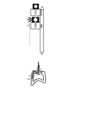
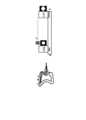
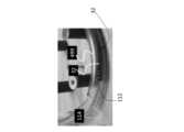
次に図面を参照すると、図1及び図2は、本明細書においてシステム10と呼ばれる本システムの典型的な手術室のセットアップ(setup)(図1)と、カート(cart)のレイアウト(図2)とを示す。モニタ12は、外科医14が手技(procedure)を監視するために使用することができる。図1に示すように、システム10は、カート20を使用して患者700の近くに配置される。システム10のモジュールは、最適なレイアウトで異なる多関節棚(articulated shelves)22に配置される(図10~図11を参照して以下にさらに説明する)。外科医は、ユーザインターフェース400及び401を介して大腸鏡24を操作する。 Referring now to the drawings, FIGS. 1 and 2 show a typical operating room setup (FIG. 1) and cart layout (FIG. 2) for the present system, referred to herein as system 10. ) and
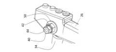
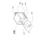
図3a~図3cは、手動ノブ28及び30を取り付けられた本体26を有する既製の大腸鏡24(Pentax EC-3831L フレキシブルビデオ大腸鏡内視鏡)を示す。外科医14は、ノブ28及び30を所望の向きに回転させることにより、シャフト33の遠位先端部32を偏向させることができる。大腸鏡24の本体26にはまた、付属アダプタ36を備えたカメラケーブル及び光源34が接続されている。 Figures 3a-3c show a prefabricated colonoscope 24 (Pentax EC-3831L flexible video colonoscope endoscope) having a
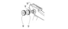
図3bは、手動ノブ28及び30に代わるアダプタ40及び42を示す。アダプタ40及び42は、ノブ入力を大腸鏡24の関節機構(articulation mechanism)へ機械的に伝える働きをするシャフト44及び46の端部に係合するように設計された鍵穴パターンを有する。アダプタ40は円形ベース48を有し、アダプタ42は円形ベース50を有する。円形ベース48及び50は、手動ノブ28及び30またはその代わりに後付けされた機械的ギアのストッパとして機能する。図3bはまた、大腸鏡24のバルブボタン52及び54であって、バルブボタン52及び54が(それぞれ)トンネル51及び53を介する吸引及び空気/水のためのインターフェースを(それぞれ)提供する、バルブボタン52及び54を示す。 FIG. 3b shows
図3cは、シャフト44及び46に取り付けられたアダプタ40及び42を示す(鍵穴はアダプタ40及び42の滑りを防止する)。 Figure 3c shows
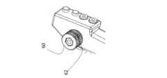
図3d~図3fは、手動ノブ28がアダプタ42に結合され、手動ノブ30がアダプタ40に結合された本発明の実施形態を示す。このような結合は、引き続き、ノブを介して大腸鏡24を手動で操作することを可能にするとともに、大腸鏡24の手動操作と電動操作との迅速な切り替えを容易にする。 3d-3f show an embodiment of the invention in which
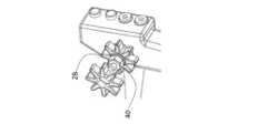
図3g~図3iは、ギア60がアダプタ40に結合され、ギア62がアダプタ42に結合されている結合を示す。このような結合を受けて、大腸鏡24には、ギア60及び62を介して関節を作動させるための駆動ユニット66が取り付けられ得る。大腸鏡24の追加機能(種々のバルブ及びボタン)を、他の駆動/制御機構に結合し、それによって大腸鏡24を手動の動作から完全に電動化された動作に変換することもできる。 3g-3i show a coupling in which gear 60 is coupled to
図4a~図4kは、駆動ユニット66の構成要素を示す。駆動ユニット66は、大腸鏡24の本体26の外面に取り付けられる。駆動ユニット66のモータは、大腸鏡24のノブ40及び42(またはギアを介してそのシャフト)に結合されて、標準的な任意の手動式大腸鏡を電動式(例えば、ロボット)大腸鏡に変換することを可能にする。 4a-4k show the components of the
図4aは、大腸鏡24に取り付けられたギア60及び62へのモータ68及び69の結合を示す。駆動ユニット66のハウジング70は、ブラケット(bracket)72を介して大腸鏡本体26に固定されている。シャーシ70の垂直プレート78に沿って取り付けられたモータ68及び69は、ウォームギア(worm gears)74及び76を介してギア60及び62に結合されている。また、垂直プレート78にはポテンショメータ80及び82が取り付けられており、これらはギア61及び63を介してウォームギア74及び76に結合されている。モータコントローラ75が、ブラケット72を介して大腸鏡本体26に固定されている。 4a shows the coupling of
図4c~図4eは、大腸鏡24のワーキングチャネルを通る「小型ツール」の前進及び作動を制御するために使用され得る、本明細書では駆動ユニット132と称される駆動ユニットを示す。 4c-4e show a drive unit, referred to herein as
大腸鏡検査では、手技の間に組織の試料採取または処理が必要になることがよくある。そのような試料採取または処理は、大腸鏡24のワーキングチャネルを通して挿入され、そのエンドエフェクタが所望の組織に近接するように大腸鏡シャフト33の遠位端から外へ配置される「小型ツール」を使用して実施することができる。その場合、外科医は、組織試料の処理または回収を行うために、エンドエフェクタ(end effector)(例えば、把持器、または投げ縄もしくは他の任意のツール)を使用することができる。 Colonoscopies often require tissue sampling or manipulation during the procedure. Such sampling or manipulation involves a "small tool" that is inserted through the working channel of
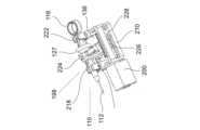
典型的な小型ツール(本明細書ではツール110と称する)を図4eに示す。ツール110は、細いフレキシブルシャフト112(典型的に、直径1.2~3.1mm、長さ60~210cm)を含む。ツール110は、シャフト112の遠位端にエンドエフェクタ114を含む。エンドエフェクタ114は、通常は、固定ハンドル118及びスライド式ボタン127を使用して、手動で操作される。シャフト112の遠位端に向かってハンドル118上のスライド式ボタン127を押すと、ツール110のジョー(jaws)が開き、逆の場合も同様である。 A typical miniature tool (referred to herein as tool 110) is shown in Figure 4e.
図4cは、ハウジング70に接続されたアダプタ130を示す。アダプタ130は、穴134を通るネジ(図示せず)を使用して、ツール110の押し引き駆動ユニット132をハウジング70に接続する。本体26のポート136は、大腸鏡24のワーキングチャネルへのアクセスを提供する。 4c shows the
図4dは、ツール110の駆動ユニット132の基本的構成要素を示す。シャフト112をワーキングチャネルの外に並進させ、エンドエフェクタ114を所望の解剖学的ランドマークに正確に位置付けるために、シャフト112はアダプタ130の溝142に挿入され、ノブ144を介して固定される。 FIG. 4d shows the basic components of the
アダプタ130は、50mmの典型的な移動範囲を有するスライダ148に接続される。スライダ148は、ネジ156と、モータ(図示せず)と、ギア160に結合されるギア158とを含むネジ機構を介して駆動される。
ツール110を使用するために、外科医は、エンドエフェクタ114がモニタ12に見えるようになるまで、シャフト112を大腸鏡24のワーキングチャネルを通してスライドさせる。それから外科医は、上記のように、シャフト112をアダプタ130に固定する。 To use
図4fは、アダプタ130を介してハウジング70に接続された駆動ユニット132を示し、溝142がポート136の中心に揃えられる。 4f shows drive
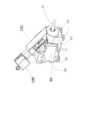
図4gは、吸引(suction)バルブ52、及び空気/水バルブ54を電動で起動させるための電動機構170を示す。 FIG. 4g shows a
ハウジング70は、ソレノイド(solenoids)182及び184のためのエンクロージャ(enclosure)として機能する突出部180であって、ソレノイド182及び184が(それぞれ)バルブ52及び54を作動させる、突出部180を含む。外科医は、図7bを参照してさらに後述するように、スイッチを介して各バルブの状態を制御する。
図4hは、駆動ユニット132と駆動ユニット66とが共通のエンクロージャ(enclosure)192を共有する構成を示す。レール194は、エンクロージャ192の一部を形成し、ツール110の開閉モジュール198のコネクタとして機能する(図4i)。モジュール198は、コネクタ200を介して、駆動ユニット132に解放可能なように接続され得る。コネクタ137は、シャーシ210の一部である。ツール110の開閉動作を起動するために、ハンドル118は、シャフト112を駆動ユニット132の方に向けた状態で、モジュール198に挿入される。ツール110のボタン127はモジュール198の開閉機構にクランプされ、モジュール198を閉じるためにカバー206がシャーシ210上をスライドする。 4h shows a configuration in which drive
図4jは、モジュール198の開閉機構を示す。ハンドル本体118は、ハウジング218及びハウジング222にクランプされ(clamped)、スライドボタン127が回転レバー224のアームにクランプされる。レバー224はサーボモータ226に接続されており、そのサーボモータはスライダ228を介してシャーシ210に接続されている。サーボモータ226のスライダ228は、レバー224の回転点(point of rotation)を最適化するために用いられ、様々な種類、長さ、及び形状の、異なる小型ツールを使用することを可能にする。 4j shows the opening and closing mechanism of
レバー224が順方向に回転すると、ハンドル127が前方に押し出される。ハンドル127は、押し引きワイヤを介してエンドエフェクタ114に接続されている。小型ツール110の押し引きワイヤを押すことで、エンドエフェクタ114のジョー機構によりジョーが開く。スライドボタン127の後退により、エンドエフェクタ114のジョーが閉じるようになる。 When the
図4kは、駆動ユニット66、132及びモジュール198の典型的な構成を示す。駆動ユニット132は、駆動ユニット66に接続されている。小型ツール遠位端エフェクタ114の開閉を作動させるモジュール198は、駆動ユニット132に接続されている。 FIG. 4k shows a typical configuration of
図4lは、ハウジング217に組み立てられた駆動ユニット66及び132ならびにモジュール198を示す。真空パッド(Vacuum pads)237は、さらに後述するように、ハウジング217を任意の平坦な表面に固定するのに使用される。 4l shows drive
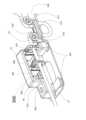
図5a~図5cは、内視鏡24のフレキシブルシャフト33を前進/後退させるための駆動ユニット300を示す。 5a-5c show a
図5aは、駆動ユニット300の斜視図である。駆動ユニット300は、100mmの直線移動範囲を有するスライダ304を直線的に駆動する電動式リニア機構302と、2つの把持用アクチュエータ308及び310とを含む。 5a is a perspective view of the
ローラ312及び314が、その間に溝316を配置してアーム315に隣接する。ローラ及び溝のセットアップにより、フレキシブルシャフト33が把持用アクチュエータ310に導かれる。カバー344が、典型的には真空パッド330を介してプレート22に接続されている。プレート22は、アーム402を介してカート20に接続される。
カバー344上のボタン340は、両方の把持用アクチュエータ(grasping actuators)(308及び310)を制御する。フレキシブルシャフト33を駆動ユニット300に取り付けるには、外科医が、ボタン340を押して把持用アクチュエータ308及び310を開き、次にフレキシブルシャフト33を把持用アクチュエータ308及び310のジョーの間に配置することができ、再びボタン340を押すことにより、フレキシブルシャフト33を把持用アクチュエータ308及び310内にロックする。 A
図5bは、駆動ユニット300の構成要素を示す。本体350は、スライダ304を本体350上で(近位(proximal)位置を示す点Pから遠位(distal)位置を示す点Dまで)駆動するネジベースのリニア駆動機構を含む。把持用アクチュエータ308は、スライダ304に取り付けられている。把持用アクチュエータ308は、スライダ304と共に直線的に移動し、以下では「移動把持用アクチュエータ」と称される。把持用アクチュエータ310は、本体350の近位端Pに取り付けられており、以下では「固定把持用アクチュエータ」と称される。把持用アクチュエータ308及び310はいずれも、フレキシブルシャフト33との接触を最適化するように設計されたカバー368を有して、様々なタイプ、長さ、コーティング材料、及び直径の、異なる内視鏡タイプの使用を可能にする。 FIG. 5b shows the components of the
図5cは、把持用アクチュエータ308及び310を示す。本体360は、モータ361と、ネジベースのリニア機構とを含む。このリニア機構は、レール366に沿ってアーム362及びアーム364を駆動する。 FIG. 5c shows the
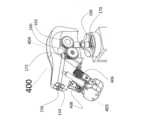
図6a~図6c及び図7a~図7bは、駆動ユニット300のユーザインターフェース(以下、インターフェース400)を示す。 6a-6c and 7a-7b show the user interface of drive unit 300 (hereinafter interface 400).
駆動ユニット300を介してシャフト33の押し引きを制御するために、外科医は、指インターフェース405(図6a~図6c)の指パッド406及び408に人差し指と親指とを係合させて、インターフェース400の本体404(図7a)のパームレスト402を把持する。指パッド406及び408は、図6bに示す開状態と、図6cに示す閉状態との間で作動させることができる。 To control the push and pull of
指パッド406及び408は、把持用アクチュエータ308及び310を制御する。指パッド406及び408が開いているとき(図6b)、把持用アクチュエータ308のジョーは開いている。指パッド406及び408が閉じられると(図6c)、把持用アクチュエータ308のジョーが閉じられ、フレキシブルシャフト33に摩擦力を加える。この摩擦力により、外科医はフレキシブルシャフト33の押し引きを制御することができる。
制御インターフェース400はまた、フレキシブルシャフト33の遠位関節部32と、吸引バルブ及び空気/水バルブとを制御する。インターフェース400による遠位関節部32の制御のメカニズム及び構造を理解するために、ここで図7bを参照する。 The
図7bは、外科医が、フレキシブルシャフト33の関節部と吸引及び空気/水機能のバルブ52、54とを(それぞれ)ボタン154及び156を介して、同時に制御することを可能にする構造と構成要素とを示す。 Figure 7b shows structures and components that allow the surgeon to simultaneously control the articulation of the
外科医は、関節部の左右上下の動きを制御するために、インターフェース本体404を所望の側及び高さまで回転させる。ポテンショメータ170、172が本体404の向きを(図7bに示すように)計測し、その電気信号が電気コントローラ75によってモータ68及び69への回転コマンドに変換される。モータ68及び69が回転すると、ウォームギア74及び76が回転し、その結果、遠位関節機構のシャフトが回転する。ウォームギア74及び76はまた、回転している間に、ギア61及び63を回転させる。ギア61、63は、回転ポテンショメータ80、81に結合されている。 The surgeon rotates the
ポテンショメータ80、81からの信号は、コントローラ75に送られ、本体404の方位ポテンショメータ170、172からの信号と比較されて、結果としてコントローラ75は、モータのポテンショメータ80、81と制御インターフェース本体404のポテンショメータ170、172とからの処理信号の計測値が、等しくなるまで、または許容差の範囲になるまで、モータに次の回転コマンドを送るようにする。 The signals from the
上記の計測及び移動のサイクルを100Hz以上の周波数でサンプリングして、関節機構の速い反応を遅らせることなく確実なものにすることができる。 The above measurement and movement cycles can be sampled at a frequency of 100 Hz or higher to ensure fast response of the joint mechanism without delay.
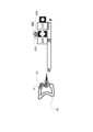
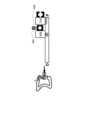
本体404は、図7aに示すように、ハウジング412に接続されている。ハウジング412は、ハウジング418の近位端414(p)と遠位端416(d)との間で直線的にスライドすることができる。リニアポテンショメータがハウジング418に配置されており、外科医がスライド式ハウジング420に沿ってハウジング412をスライドさせると、リニアポテンショメータ415のスライダがインターフェース本体404の位置及び方向を計測する。インターフェース400の本体404の組み合わせ計測と指のパッド406及び408の状態とにより、図9a~図9gで詳細に説明するように、外科医が駆動ユニット300を制御できるようになる。
押し引きモジュール132によって「小型ツール」シャフトを制御するために、外科医は、インターフェース401の本体407のパーム(palm)部をつかみ(図7c)、ハウジング419をスライド式ハウジング429に沿ってスライドさせ、ポテンショメータスライダがインターフェース本体407の位置を計測する。ポテンショメータからの位置信号は、コントローラ75に送られ、その信号をコントローラ75は、「小型ツール」シャフト112を駆動するモジュール132への動作コマンドに変換する。シャフト112の直線運動を制御しながら、外科医は、指インターフェース405のパッド406及び408の開閉状態を制御することにより、エンドエフェクタ114の起動を同時に制御することができる。コントローラ75は、指のパッド406及び408の状態を計測し、それに応じて開閉モジュール198を作動させ、外科医が、「小型ツール」シャフト112遠位端の位置を制御し、同時にエンドエフェクタ114の起動を制御することを可能にする。 To control the "small tool" shaft by push-
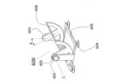
図8a~図8hは、フレキシブルシャフトの長軸方向のロール運動を可能にする拡張用電動モジュールを示す。外科医は、このロール運動を利用して、GI内でフレキシブルシャフトを前進させる際に、フレキシブルシャフトの遠位端をより適切に配置することができる。 Figures 8a-8h show an expansion motorized module that allows longitudinal roll motion of the flexible shaft. The surgeon can use this rolling motion to better position the distal end of the flexible shaft as it is advanced within the GI.
内視鏡フレキシブルシャフト33を回転させるために、モジュール500がコネクタ510を介して押し引きモジュール300に接続されて、フレキシブルシャフトの中心である点Cを円弧部508の中心に位置決めする。円弧部508は、フレーム502にヒンジ式に接続されている。円弧部508は、その遠位端に、ウォームギア506と噛み合うギア507を含む。モータ504がウォームギアを回転させる。モータ504がインターフェース400によって起動されると(図8e~図8hを参照して説明される)、図8c~図8dに示すように、押し引きモジュール300は点Cの周りを回転する。 To rotate endoscope
図8e~図8hは、拡張用回転フレームモジュール600を示す。モジュール600は、真空レッグ604を有する固定台606で構成されている。フレーム608は、ヒンジ603及び605を介して固定フレーム606にヒンジ式に接続されている。回転センサ602は、ヒンジ605に接続され、角度αを連続的に計測する。大腸鏡シャフトの中心周りの回転を制御するために、インターフェース400は、真空パッド150を介して回転フレーム608の表面607に取り付けられる。大腸鏡シャフトを回転させるために、外科医はインターフェースを傾け、それによってフレーム608を同様に回転させる。回転センサの計測値は、モジュール300を中心点Cの周りに回転させるモータ504の入力として役立つ。図8g~図8hは、フレーム608の傾斜位置を例示する。このようなインターフェース構成により、外科医は、フレキシブルシャフト33の押し引き動作、遠位端32の関節部(上下左右)、及びフレキシブルシャフト33のロール角度を、同時にかつ直感的に制御できるようになる。 8e-8h show an expansion rotating
把持用アクチュエータ308のいくつかの動作状態がある。すなわち、
(i)閉じて静止した状態、
(ii)開いて静止した状態、
(iii)閉じて遠位へ(患者の体に向かって)移動する状態、
(iv)閉じて近位へ(患者の体から離れて)移動する状態、
(v)開いて遠位へ移動する状態、及び
(vi)開いて近位へ移動する状態、
である。There are several operating states for the
(i) closed and stationary;
(ii) open and stationary;
(iii) closing and moving distally (towards the patient's body);
(iv) closing and moving proximally (away from the patient's body);
(v) open and move distally; and (vi) open and move proximally.
is.
図9a~図9gは、インターフェース400の入力と駆動ユニット300の対応する機械的出力とのシーケンスを概略的に示す。 9a-9g schematically show the sequence of inputs of the
図9aは、患者の下部消化管内の点Aに遠位端が位置するフレキシブルシャフト33を概略的に図示する。指パッド406及び408は開状態であり、把持用アクチュエータ308も同様に開いている。把持用アクチュエータ310は、大腸鏡シャフト33の望ましくない動きを排除するために、閉じられている。 Figure 9a schematically illustrates a
図9bは、閉状態の指パッド406及び408を示し、把持用アクチュエータ308も同様に閉じてフレキシブルシャフト33を把持している。把持用アクチュエータ310は開いているが、外科医がパームレスト404を動かしていないので、シャフト33は動かない。 9b shows
外科医が、指パッド406及び408を閉じた状態でインターフェース本体404を点Dへ向けて遠位に動かすと、把持アクチュエータ308が点Dに向かって移動する。把持用アクチュエータ310が開いているので、フレキシブルシャフト33は患者の消化管内で点Aから点Bに並進される。 When the surgeon moves
シャフト33を点Bから点Cに進めるために、外科医は指パッド406及び408を開き、したがって把持用アクチュエータ310を閉じ、把持用アクチュエータ308を開く(図9d)。次に、外科医は、インターフェース本体404を点Pにスライドさせ、そして外科医は、指パッド406及び408を閉じ、したがって把持用アクチュエータ308を閉じ、把持用アクチュエータ310を開く。指パッド406及び408を閉じた状態でインターフェース本体404を遠位に動かすと(図9g)、フレキシブルシャフト33が点Cへ移動することになる。この一連の事象は、大腸鏡のシャフトを手でつまんで引っ張るのと似ており、外科医は、新しいスキルや手術手技を習得する必要なく、手作業を模倣した直感的な方法で、フレキシブルシャフト33を前後に引っ張ることを可能にする。外科医は、例えば触覚フィードバックが必要な場合などには、いつでも、フレキシブルシャフト33の動きを手動で制御することを選択できることに留意されたい。 To advance
パームレスト本体404の直線運動とフレキシブルシャフト33の遠位端の移動との間のスケールは、外科医が、その必要性に応じて、処置中にいつでも選択することができる。典型的なスケールは、1:0.5~1:4の範囲である。 The scale between the linear motion of
本発明のシステム10は、以下のように下部消化管の処置(例えば、大腸鏡検査)に使用することができる。 The
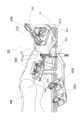
図10は、下部消化管処置に使用することができるシステム10の典型的なセットアップを示す。患者700は、背中をシステム10に向けて横向きに寝ている。フレキシブルシャフト33の遠位端は、肛門外口を通して患者の下部消化管に挿入される。駆動ユニット300が所望の位置に移動され、フレキシブルシャフト33が駆動ユニット300に装備され、両方の把持用アクチュエータ(308及び310)によって把持される。棚22に配置された台217に組み立てられた共通のカバー192を有する駆動ユニット66、132及び198は、アーム422及び423により、駆動ユニット300に対して最適な位置に動かされる。フレキシブルシャフト33のたるみは、先輪(leading wheels)312、314によって処理される。大腸鏡制御インターフェース400及び小型ツール制御インターフェース401は、外科医の都合に合わせて異なるプレート上に配置される。 FIG. 10 shows a typical setup of
手術をするために、外科医は、両方のインターフェース400及び401をつかみ、下部消化管を通してフレキシブルシャフト33を移動させる。外科医は、インターフェース400を使用して、フレキシブルシャフトの遠位端を患者の解剖学的構造に対して最適な位置及び関節部方位に配置し、同時に、インターフェース401を使用して、小型ツールエンドエフェクタの位置及び起動を制御することができる。外科医は、いつでも、インターフェース本体404の前部に位置するボタン154及び156(図7bに示す)を押すことにより、吸引/灌注(irrigation)システム及び空気システムを操作することができる。また、外科医は、例えば触覚フィードバックが必要な場合など、フレキシブルシャフト33及び/または小型ツールの動きを手動で制御するために、いつでも、内視鏡及び小型ツールを電動モジュールから切り離すことを選択することができる。 To operate, the surgeon grasps both
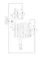
図11は、本システムを取り付けられ、任意選択で本システムによって制御される、大腸鏡による作業モード選択を説明するブロック図である。 FIG. 11 is a block diagram illustrating working mode selection by a colonoscope fitted with and optionally controlled by the system.
外科医は、処置のために大腸鏡を準備するとき、開始時における好ましい作業モードを選択することができる。外科医が手動モード(図の左側の分岐)から始めたい場合は、アダプタに手動ノブを取り付ける。外科医が電動モード(図の右側の分岐)から始めたい場合は、アダプタにギアを取り付け、そして上記の電動式駆動ユニットを取り付ける。 A surgeon can select a preferred working mode at the start when preparing the colonoscope for the procedure. A manual knob is attached to the adapter if the surgeon wishes to start in manual mode (left branch of figure). If the surgeon wishes to start in electric mode (right branch of the diagram), attach the gear to the adapter and attach the motorized drive unit described above.
手技のどの段階でも、外科医は、電動モードと手動モードとを交互に切り替えることができる。例えば、外科医が手動モードで作業していて、電動モードに切り替えたい場合、外科医は、手動ノブを取り外し、ギア、アダプタ、及び駆動ユニットを取り付けるだけでよい。外科医が手動モードに切り替えたい場合には、この手技を逆にすることができる。 At any stage of the procedure, the surgeon can alternate between powered and manual modes. For example, if a surgeon is working in manual mode and wants to switch to electric mode, the surgeon simply removes the manual knob and installs gears, adapters and drive units. This procedure can be reversed if the surgeon wishes to switch to manual mode.
本明細書で使用するとき、「約」という用語は、±10%を意味する。 As used herein, the term "about" means ±10%.
本発明のさらなる目的、利点、及び新規な特徴が、限定を意図しない以下の実施例を検討することにより、当業者に明らかになるであろう。 Further objects, advantages and novel features of the present invention will become apparent to those skilled in the art upon review of the following non-limiting examples.
次に、上記の説明に加えて、本発明を非限定的に説明する、以下の実施例を参照されたい。 In addition to the above description, reference is now made to the following examples, which illustrate the invention in a non-limiting manner.
プロトタイプシステムのベンチテスト
本システムのプロトタイプを作成し、機能性についてベンチテストを行った。Bench Test of Prototype System A prototype of the system was built and bench tested for functionality.
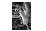
図12a~図12bは、操作者の手がインターフェース400の本体404を把持している状態で、フレキシブルシャフトのインターフェース400を示す。フレキシブルシャフト33の遠位部分32は、本体404の向き(図12aでは右、図12bでは上)に従って関節運動する。 12a-12b show the
押し引きモジュール300もまた、これらの図に示す。指インターフェースのパッド406、408が、開位置にある(そして把持器308が開き、固定把持器310が閉じている)。 A push-
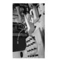
GIシミュレータ(499と表す)を使用して、フレキシブルシャフトの操縦試験を行った(図12c~図12g)。図12cは、GIシミュレータにおける遠位部分32を有するフレキシブルシャフト33の動きを示す。図12dは、シャフト33遠位部分32の遠位端から送達される小型ツール110の「小型ツール」シャフト112及び把持器114の遠位端を示す。図12eは、本システムの関節制御能力を示しており、遠位部分32が関節運動してGIシミュレータの外に進む様子を示す。図12fは、GIシミュレータから外へフレキシブルシャフト33を進ませながら、小型ツール110(シャフト112及びエンドエフェクタ114)を制御する能力を示す。図12gは、小型ツール110の付随制御を伴うフレキシブルシャフト33の遠位関節部32の制御を示す。図12hは、把持器308及び310が開位置にある状態でのフレキシブルシャフト33に対する手動制御を示す。 A GI simulator (denoted as 499) was used to perform maneuvering tests of the flexible shaft (FIGS. 12c-12g). Figure 12c shows the movement of
明確にするために、別々の実施形態の文脈で説明されている本発明の特定の特徴は、単一の実施形態において組み合わせて提供されることも可能であることが理解される。逆に、簡潔にするために、単一の実施形態の文脈で説明されている本発明の様々な特徴は、別々に、または任意の好適な部分的組み合わせで提供されることも可能である。 It is understood that specific features of the invention, which are, for clarity, described in the context of separate embodiments, may also be provided in combination in a single embodiment. Conversely, various features of the invention which are, for brevity, described in the context of a single embodiment, can also be provided separately or in any suitable subcombination.
本発明をその特定の実施形態に関連して説明したが、多くの代替案、修正及び変形が当業者には明らかであろうことは明白である。したがって、添付の特許請求の範囲の趣旨及び広い範囲に含まれるそのような全ての代替案、修正及び変形を包含することが意図されている。本明細書に記載されている全ての刊行物、特許及び特許出願は、個々の刊行物、特許または特許出願が参照により本明細書に組み込まれることが具体的かつ個別に示されているのと同じ程度に、参照によりその全体が本明細書に組み込まれる。さらに、本出願における参考文献の引用または識別は、そのような参考文献が本発明の先行技術として利用可能であることを認めるものと解釈されるべきではない。セクションの見出しが使用されている場合、それらは必ずしも限定的であると解釈されるべきではない。さらに、本出願のいずれの優先権書類(複数可)も、その全体が本明細書に組み込まれる。
Although the invention has been described in relation to specific embodiments thereof, it is evident that many alternatives, modifications and variations will be apparent to those skilled in the art. Accordingly, it is intended to embrace all such alternatives, modifications and variations that fall within the spirit and broad scope of the appended claims. All publications, patents and patent applications mentioned in this specification are specifically and individually indicated that each individual publication, patent or patent application is incorporated herein by reference. To the same extent, it is incorporated herein by reference in its entirety. In addition, citation or identification of any reference in this application shall not be construed as an admission that such reference is available as prior art to the present invention. Where section headings are used, they should not necessarily be construed as limiting. Furthermore, any priority document(s) of this application are hereby incorporated in their entirety.
Claims (8)
Translated fromJapanese(a)大腸鏡のハウジングの外部に取り付けられた第1の駆動ユニットであって、前記第1の駆動ユニットが、前記2つの回転ノブまたは前記2つの回転ノブに代わるギアと係合するための第1の駆動機構を含む、前記第1の駆動ユニットと、
(b)前記内視鏡の前記シャフトに取り付け可能な第2の駆動ユニットであって、前記第2の駆動ユニットが、前記シャフトを前後に直線的に並進させることが可能である、前記第2の駆動ユニットと、
(c)枢動支持体に取り付けられた第1のインターフェースを含むユーザインターフェースであって、前記第1のインターフェースが手のひらによって係合可能であり、前記ユーザインターフェースが前記第1の駆動機構を制御するためのものである、前記ユーザインターフェースと、
を備える、前記制御システム。A control system for a colonoscope having a shaft deflectable via two rotary knobs, said control system comprising:
(a) a first drive unit mounted externally to the housing of the colonoscope, said first drive unit for engaging said two rotation knobs or a gear replacing said two rotation knobs; the first drive unit comprising a first drive mechanism;
(b) a second drive unit attachable to the shaft of the endoscope, wherein the second drive unit is capable of linearly translating the shaft back and forth; a drive unit of
(c) a user interface including a first interface attached to a pivot support, said first interface being engageable by a palm, said user interface controlling said first drive mechanism; the user interface for
The control system, comprising:
Applications Claiming Priority (3)
| Application Number | Priority Date | Filing Date | Title |
|---|---|---|---|
| US202062981569P | 2020-02-26 | 2020-02-26 | |
| US62/981,569 | 2020-02-26 | ||
| PCT/IL2021/050211WO2021171292A1 (en) | 2020-02-26 | 2021-02-24 | Control system for a colonoscope |
Publications (2)
| Publication Number | Publication Date |
|---|---|
| JP2023515085Atrue JP2023515085A (en) | 2023-04-12 |
| JPWO2021171292A5 JPWO2021171292A5 (en) | 2024-02-27 |
Family
ID=77490773
Family Applications (1)
| Application Number | Title | Priority Date | Filing Date |
|---|---|---|---|
| JP2022549937APendingJP2023515085A (en) | 2020-02-26 | 2021-02-24 | colonoscopy control system |
Country Status (5)
| Country | Link |
|---|---|
| US (1) | US12433474B2 (en) |
| EP (1) | EP4110160A4 (en) |
| JP (1) | JP2023515085A (en) |
| CN (1) | CN115334952A (en) |
| WO (1) | WO2021171292A1 (en) |
Families Citing this family (1)
| Publication number | Priority date | Publication date | Assignee | Title |
|---|---|---|---|---|
| CN115334952A (en) | 2020-02-26 | 2022-11-11 | 人类拓展有限公司 | Control system for colonoscope |
Citations (6)
| Publication number | Priority date | Publication date | Assignee | Title |
|---|---|---|---|---|
| JPH042318A (en)* | 1990-04-20 | 1992-01-07 | Olympus Optical Co Ltd | Endoscope |
| US5159446A (en)* | 1991-06-21 | 1992-10-27 | Olympus Optical Co., Ltd. | Electronic endoscope system provided with a separate camera controlling unit and motor controlling unit |
| JPH1132977A (en)* | 1997-07-17 | 1999-02-09 | Olympus Optical Co Ltd | Endoscope system |
| JP2006527600A (en)* | 2003-06-16 | 2006-12-07 | エシコン・エンド−サージェリィ・インコーポレイテッド | Surgical system with stapling equipment and retractor |
| CN106491211A (en)* | 2016-09-30 | 2017-03-15 | 江苏风和医疗器材有限公司 | A kind of anastomat fires force checking device |
| JP2018526042A (en)* | 2015-08-11 | 2018-09-13 | ヒューマン エクステンションズ リミテッド | Control unit for flexible endoscope |
Family Cites Families (6)
| Publication number | Priority date | Publication date | Assignee | Title |
|---|---|---|---|---|
| JPH042318Y2 (en) | 1985-01-28 | 1992-01-27 | ||
| US7789825B2 (en) | 2003-09-29 | 2010-09-07 | Ethicon Endo-Surgery, Inc. | Handle for endoscopic device |
| WO2011119521A1 (en)* | 2010-03-22 | 2011-09-29 | Tufts Medical Center, Inc. | Fiber optic intubating device |
| CN104027061B (en)* | 2012-04-24 | 2016-07-06 | 王东 | Soft endoscope system based on automatically controlled driving instruments |
| US10709316B2 (en)* | 2017-06-06 | 2020-07-14 | Eladio A. Vargas | Method and apparatus for a rotating sleeve for endoscopic propulsion with mitigation of colonoscopic perforation |
| CN115334952A (en) | 2020-02-26 | 2022-11-11 | 人类拓展有限公司 | Control system for colonoscope |
- 2021
- 2021-02-24CNCN202180022587.4Apatent/CN115334952A/enactivePending
- 2021-02-24WOPCT/IL2021/050211patent/WO2021171292A1/ennot_activeCeased
- 2021-02-24JPJP2022549937Apatent/JP2023515085A/enactivePending
- 2021-02-24USUS17/801,814patent/US12433474B2/enactiveActive
- 2021-02-24EPEP21761572.3Apatent/EP4110160A4/enactivePending
Patent Citations (6)
| Publication number | Priority date | Publication date | Assignee | Title |
|---|---|---|---|---|
| JPH042318A (en)* | 1990-04-20 | 1992-01-07 | Olympus Optical Co Ltd | Endoscope |
| US5159446A (en)* | 1991-06-21 | 1992-10-27 | Olympus Optical Co., Ltd. | Electronic endoscope system provided with a separate camera controlling unit and motor controlling unit |
| JPH1132977A (en)* | 1997-07-17 | 1999-02-09 | Olympus Optical Co Ltd | Endoscope system |
| JP2006527600A (en)* | 2003-06-16 | 2006-12-07 | エシコン・エンド−サージェリィ・インコーポレイテッド | Surgical system with stapling equipment and retractor |
| JP2018526042A (en)* | 2015-08-11 | 2018-09-13 | ヒューマン エクステンションズ リミテッド | Control unit for flexible endoscope |
| CN106491211A (en)* | 2016-09-30 | 2017-03-15 | 江苏风和医疗器材有限公司 | A kind of anastomat fires force checking device |
Also Published As
| Publication number | Publication date |
|---|---|
| EP4110160A1 (en) | 2023-01-04 |
| WO2021171292A1 (en) | 2021-09-02 |
| EP4110160A4 (en) | 2024-03-27 |
| US20230104573A1 (en) | 2023-04-06 |
| US12433474B2 (en) | 2025-10-07 |
| CN115334952A (en) | 2022-11-11 |
Similar Documents
| Publication | Publication Date | Title |
|---|---|---|
| US12295604B2 (en) | Control unit for a medical device | |
| JP6845809B2 (en) | Control unit for flexible endoscopes | |
| EP2116175B1 (en) | Medical system | |
| US20200000539A1 (en) | Controller for surgical tools | |
| JP2023515085A (en) | colonoscopy control system | |
| JP2022183138A (en) | Tendon-sheath drive, surgical element drive, and method of operation | |
| CN218338515U (en) | Surgical instrument assembly, surgical instrument control unit and endoscopic surgical device | |
| CN117100405A (en) | Surgical robot for clamping hand, double mechanical arms and performing surgery through natural cavity | |
| CN115120352A (en) | Endoscopic surgical equipment | |
| CN120770937A (en) | Main control equipment capable of single-finger operation and main hand control console | |
| HK40008022B (en) | Control unit for a medical device | |
| HK40008022A (en) | Control unit for a medical device | |
| HK1253926A1 (en) | Control unit attachable to an endoscope having a shaft deflectable via two rotatable knobs to allow one-handed operation of the knobs | |
| HK1253926B (en) | Control unit attachable to an endoscope having a shaft deflectable via two rotatable knobs to allow one-handed operation of the knobs |
Legal Events
| Date | Code | Title | Description |
|---|---|---|---|
| A521 | Request for written amendment filed | Free format text:JAPANESE INTERMEDIATE CODE: A821 Effective date:20221006 | |
| RD01 | Notification of change of attorney | Free format text:JAPANESE INTERMEDIATE CODE: A7426 Effective date:20221005 | |
| A521 | Request for written amendment filed | Free format text:JAPANESE INTERMEDIATE CODE: A523 Effective date:20240216 | |
| A621 | Written request for application examination | Free format text:JAPANESE INTERMEDIATE CODE: A621 Effective date:20240216 | |
| A977 | Report on retrieval | Free format text:JAPANESE INTERMEDIATE CODE: A971007 Effective date:20241217 | |
| A131 | Notification of reasons for refusal | Free format text:JAPANESE INTERMEDIATE CODE: A131 Effective date:20250114 | |
| A131 | Notification of reasons for refusal | Free format text:JAPANESE INTERMEDIATE CODE: A131 Effective date:20250805 | |
| A711 | Notification of change in applicant | Free format text:JAPANESE INTERMEDIATE CODE: A711 Effective date:20250909 |