JP2023514436A - A prism for redirecting the main beam of a reflector antenna - Google Patents
A prism for redirecting the main beam of a reflector antennaDownload PDFInfo
- Publication number
- JP2023514436A JP2023514436AJP2022550797AJP2022550797AJP2023514436AJP 2023514436 AJP2023514436 AJP 2023514436AJP 2022550797 AJP2022550797 AJP 2022550797AJP 2022550797 AJP2022550797 AJP 2022550797AJP 2023514436 AJP2023514436 AJP 2023514436A
- Authority
- JP
- Japan
- Prior art keywords
- prism
- antenna
- microwave
- reflector
- horn
- Prior art date
- Legal status (The legal status is an assumption and is not a legal conclusion. Google has not performed a legal analysis and makes no representation as to the accuracy of the status listed.)
- Granted
Links
Images
Classifications
- H—ELECTRICITY
- H01—ELECTRIC ELEMENTS
- H01Q—ANTENNAS, i.e. RADIO AERIALS
- H01Q13/00—Waveguide horns or mouths; Slot antennas; Leaky-waveguide antennas; Equivalent structures causing radiation along the transmission path of a guided wave
- H01Q13/02—Waveguide horns
- H—ELECTRICITY
- H01—ELECTRIC ELEMENTS
- H01Q—ANTENNAS, i.e. RADIO AERIALS
- H01Q19/00—Combinations of primary active antenna elements and units with secondary devices, e.g. with quasi-optical devices, for giving the antenna a desired directional characteristic
- H01Q19/10—Combinations of primary active antenna elements and units with secondary devices, e.g. with quasi-optical devices, for giving the antenna a desired directional characteristic using reflecting surfaces
- H01Q19/12—Combinations of primary active antenna elements and units with secondary devices, e.g. with quasi-optical devices, for giving the antenna a desired directional characteristic using reflecting surfaces wherein the surfaces are concave
- H01Q19/13—Combinations of primary active antenna elements and units with secondary devices, e.g. with quasi-optical devices, for giving the antenna a desired directional characteristic using reflecting surfaces wherein the surfaces are concave the primary radiating source being a single radiating element, e.g. a dipole, a slot, a waveguide termination
- H01Q19/132—Horn reflector antennas; Off-set feeding
- H—ELECTRICITY
- H01—ELECTRIC ELEMENTS
- H01Q—ANTENNAS, i.e. RADIO AERIALS
- H01Q1/00—Details of, or arrangements associated with, antennas
- H01Q1/12—Supports; Mounting means
- H01Q1/125—Means for positioning
- H—ELECTRICITY
- H01—ELECTRIC ELEMENTS
- H01Q—ANTENNAS, i.e. RADIO AERIALS
- H01Q1/00—Details of, or arrangements associated with, antennas
- H01Q1/12—Supports; Mounting means
- H01Q1/22—Supports; Mounting means by structural association with other equipment or articles
- H01Q1/24—Supports; Mounting means by structural association with other equipment or articles with receiving set
- H01Q1/247—Supports; Mounting means by structural association with other equipment or articles with receiving set with frequency mixer, e.g. for direct satellite reception or Doppler radar
- H—ELECTRICITY
- H01—ELECTRIC ELEMENTS
- H01Q—ANTENNAS, i.e. RADIO AERIALS
- H01Q15/00—Devices for reflection, refraction, diffraction or polarisation of waves radiated from an antenna, e.g. quasi-optical devices
- H01Q15/0006—Devices acting selectively as reflecting surface, as diffracting or as refracting device, e.g. frequency filtering or angular spatial filtering devices
- H01Q15/0086—Devices acting selectively as reflecting surface, as diffracting or as refracting device, e.g. frequency filtering or angular spatial filtering devices said selective devices having materials with a synthesized negative refractive index, e.g. metamaterials or left-handed materials
- H—ELECTRICITY
- H01—ELECTRIC ELEMENTS
- H01Q—ANTENNAS, i.e. RADIO AERIALS
- H01Q15/00—Devices for reflection, refraction, diffraction or polarisation of waves radiated from an antenna, e.g. quasi-optical devices
- H01Q15/02—Refracting or diffracting devices, e.g. lens, prism
- H01Q15/04—Refracting or diffracting devices, e.g. lens, prism comprising wave-guiding channel or channels bounded by effective conductive surfaces substantially perpendicular to the electric vector of the wave, e.g. parallel-plate waveguide lens
- H—ELECTRICITY
- H01—ELECTRIC ELEMENTS
- H01Q—ANTENNAS, i.e. RADIO AERIALS
- H01Q15/00—Devices for reflection, refraction, diffraction or polarisation of waves radiated from an antenna, e.g. quasi-optical devices
- H01Q15/02—Refracting or diffracting devices, e.g. lens, prism
- H01Q15/08—Refracting or diffracting devices, e.g. lens, prism formed of solid dielectric material
- H—ELECTRICITY
- H01—ELECTRIC ELEMENTS
- H01Q—ANTENNAS, i.e. RADIO AERIALS
- H01Q15/00—Devices for reflection, refraction, diffraction or polarisation of waves radiated from an antenna, e.g. quasi-optical devices
- H01Q15/14—Reflecting surfaces; Equivalent structures
- H01Q15/16—Reflecting surfaces; Equivalent structures curved in two dimensions, e.g. paraboloidal
- H—ELECTRICITY
- H01—ELECTRIC ELEMENTS
- H01Q—ANTENNAS, i.e. RADIO AERIALS
- H01Q15/00—Devices for reflection, refraction, diffraction or polarisation of waves radiated from an antenna, e.g. quasi-optical devices
- H01Q15/23—Combinations of reflecting surfaces with refracting or diffracting devices
- H—ELECTRICITY
- H01—ELECTRIC ELEMENTS
- H01Q—ANTENNAS, i.e. RADIO AERIALS
- H01Q19/00—Combinations of primary active antenna elements and units with secondary devices, e.g. with quasi-optical devices, for giving the antenna a desired directional characteristic
- H01Q19/06—Combinations of primary active antenna elements and units with secondary devices, e.g. with quasi-optical devices, for giving the antenna a desired directional characteristic using refracting or diffracting devices, e.g. lens
- H01Q19/08—Combinations of primary active antenna elements and units with secondary devices, e.g. with quasi-optical devices, for giving the antenna a desired directional characteristic using refracting or diffracting devices, e.g. lens for modifying the radiation pattern of a radiating horn in which it is located
- H—ELECTRICITY
- H01—ELECTRIC ELEMENTS
- H01Q—ANTENNAS, i.e. RADIO AERIALS
- H01Q19/00—Combinations of primary active antenna elements and units with secondary devices, e.g. with quasi-optical devices, for giving the antenna a desired directional characteristic
- H01Q19/10—Combinations of primary active antenna elements and units with secondary devices, e.g. with quasi-optical devices, for giving the antenna a desired directional characteristic using reflecting surfaces
- H01Q19/18—Combinations of primary active antenna elements and units with secondary devices, e.g. with quasi-optical devices, for giving the antenna a desired directional characteristic using reflecting surfaces having two or more spaced reflecting surfaces
- H01Q19/19—Combinations of primary active antenna elements and units with secondary devices, e.g. with quasi-optical devices, for giving the antenna a desired directional characteristic using reflecting surfaces having two or more spaced reflecting surfaces comprising one main concave reflecting surface associated with an auxiliary reflecting surface
- H01Q19/191—Combinations of primary active antenna elements and units with secondary devices, e.g. with quasi-optical devices, for giving the antenna a desired directional characteristic using reflecting surfaces having two or more spaced reflecting surfaces comprising one main concave reflecting surface associated with an auxiliary reflecting surface wherein the primary active element uses one or more deflecting surfaces, e.g. beam waveguide feeds
- H—ELECTRICITY
- H01—ELECTRIC ELEMENTS
- H01Q—ANTENNAS, i.e. RADIO AERIALS
- H01Q3/00—Arrangements for changing or varying the orientation or the shape of the directional pattern of the waves radiated from an antenna or antenna system
- H01Q3/02—Arrangements for changing or varying the orientation or the shape of the directional pattern of the waves radiated from an antenna or antenna system using mechanical movement of antenna or antenna system as a whole
- H01Q3/08—Arrangements for changing or varying the orientation or the shape of the directional pattern of the waves radiated from an antenna or antenna system using mechanical movement of antenna or antenna system as a whole for varying two co-ordinates of the orientation
- H—ELECTRICITY
- H01—ELECTRIC ELEMENTS
- H01Q—ANTENNAS, i.e. RADIO AERIALS
- H01Q3/00—Arrangements for changing or varying the orientation or the shape of the directional pattern of the waves radiated from an antenna or antenna system
- H01Q3/12—Arrangements for changing or varying the orientation or the shape of the directional pattern of the waves radiated from an antenna or antenna system using mechanical relative movement between primary active elements and secondary devices of antennas or antenna systems
- H01Q3/14—Arrangements for changing or varying the orientation or the shape of the directional pattern of the waves radiated from an antenna or antenna system using mechanical relative movement between primary active elements and secondary devices of antennas or antenna systems for varying the relative position of primary active element and a refracting or diffracting device
- H—ELECTRICITY
- H01—ELECTRIC ELEMENTS
- H01Q—ANTENNAS, i.e. RADIO AERIALS
- H01Q3/00—Arrangements for changing or varying the orientation or the shape of the directional pattern of the waves radiated from an antenna or antenna system
- H01Q3/12—Arrangements for changing or varying the orientation or the shape of the directional pattern of the waves radiated from an antenna or antenna system using mechanical relative movement between primary active elements and secondary devices of antennas or antenna systems
- H01Q3/16—Arrangements for changing or varying the orientation or the shape of the directional pattern of the waves radiated from an antenna or antenna system using mechanical relative movement between primary active elements and secondary devices of antennas or antenna systems for varying relative position of primary active element and a reflecting device
- H01Q3/20—Arrangements for changing or varying the orientation or the shape of the directional pattern of the waves radiated from an antenna or antenna system using mechanical relative movement between primary active elements and secondary devices of antennas or antenna systems for varying relative position of primary active element and a reflecting device wherein the primary active element is fixed and the reflecting device is movable
- H—ELECTRICITY
- H01—ELECTRIC ELEMENTS
- H01Q—ANTENNAS, i.e. RADIO AERIALS
- H01Q5/00—Arrangements for simultaneous operation of antennas on two or more different wavebands, e.g. dual-band or multi-band arrangements
- H01Q5/50—Feeding or matching arrangements for broad-band or multi-band operation
- H01Q5/55—Feeding or matching arrangements for broad-band or multi-band operation for horn or waveguide antennas
- H—ELECTRICITY
- H04—ELECTRIC COMMUNICATION TECHNIQUE
- H04B—TRANSMISSION
- H04B7/00—Radio transmission systems, i.e. using radiation field
- H04B7/14—Relay systems
- H04B7/15—Active relay systems
- H04B7/185—Space-based or airborne stations; Stations for satellite systems
- H04B7/1851—Systems using a satellite or space-based relay
- H04B7/18517—Transmission equipment in earth stations
Landscapes
- Engineering & Computer Science (AREA)
- Physics & Mathematics (AREA)
- Radar, Positioning & Navigation (AREA)
- Remote Sensing (AREA)
- Electromagnetism (AREA)
- Astronomy & Astrophysics (AREA)
- Aviation & Aerospace Engineering (AREA)
- General Physics & Mathematics (AREA)
- Computer Networks & Wireless Communication (AREA)
- Signal Processing (AREA)
- Aerials With Secondary Devices (AREA)
Abstract
Translated fromJapanese
Description
Translated fromJapanese <関連出願>
本願は、2020年2月25日に出願された米国仮出願第62/981,367号の優先権の利益を主張するものである。本願はこの仮出願の内容に依拠したものであり、この仮出願の内容はその全体を引用することにより本明細書の一部をなすものとする。<Related application>
This application claims the priority benefit of US Provisional Application No. 62/981,367, filed February 25, 2020. This application relies on the contents of this provisional application, which is hereby incorporated by reference in its entirety.
1997年6月30日に出願され、2000年6月13日に付与された「Multiple-feed Electromagnetic Signal Receiving Apparatus」と題するChen他の米国特許第6075497号と、2014年7月7日に出願され、2017年8月1日に付与された「Horn lens antenna」と題するHaziza、Dedi Davidの米国特許第9722316号と、2016年3月11日に出願され、2018年12月18日に付与された「Antenna horn with suspended dielectric tuning vane」と題するCook、Scottの米国特許第10158177号とは、引用することにより本明細書の一部をなすものとする。 Chen et al., U.S. Pat. No. 6,075,497, entitled "Multiple-feed Electromagnetic Signal Receiving Apparatus," filed Jun. 30, 1997 and granted Jun. 13, 2000; , Haziza, Dedi David, U.S. Pat. No. 9,722,316, entitled "Horn lens antenna", granted Aug. 1, 2017; Cook, Scott, US Pat. No. 10158177 entitled "Antenna horn with suspended dielectric tuning vane" is incorporated herein by reference.
マイクロ波周波数帯における衛星通信は、単方向性であるか双方向性であるかを問わず、大量のデータを広い地理的領域に配信できるようにする一方で、大きい信号強度を維持すべく所望の衛星に対し正確に方向付けられなければならない大型のアンテナを必要とする。マイクロ波(C帯、X帯、Ku帯、Ka帯、及びさらに高い帯域)用途の最も一般的な衛星アンテナは、ホーン照射反射鏡である。これは、多種多様な形状、サイズ、及び動作周波数が利用可能な、中央給電又はオフセット給電がなされる放物型(またはほぼ放物型)の反射鏡である。 Satellite communications in the microwave frequency band, whether unidirectional or bidirectional, are desirable to allow large amounts of data to be distributed over large geographic areas while maintaining high signal strength. requires a large antenna that must be precisely oriented with respect to the satellites. The most common satellite antenna for microwave (C-band, X-band, Ku-band, Ka-band, and higher) applications is the horn-illuminated reflector. This is a center-fed or offset-fed parabolic (or nearly parabolic) reflector available in a wide variety of shapes, sizes, and operating frequencies.
非静止軌道(non-geostationary orbit, NGSO)衛星と通信するために使用される移動プラットフォーム及び地上ターミナルは、典型的には、地上ターミナルまたは衛星の一方が他方に対して動いている間に接続を維持するためのモータ付き追跡システム及び電子機器を有する。しかし、このハードウェアは非常に高価である。GEO(Geostationary Earth Orbit, 対地静止軌道)衛星と通信する静止した地上ロケーションの場合は、いったん衛星に方向付けられ、次いで定位置でロックされた固定アンテナは、コストの点で効率的でありシンプルである。しかし、固定反射鏡の欠点は、アンテナが接続される衛星を変えるためには、熟練した作業者あるいはそれに準ずる者とツールが必要なことである。これにより、加入者が自身のサービス提供者または放送局を変えにくくなり、また、サービス提供者または放送局が容量の点で、商業的に、または他の理由で衛星または運営者を変えづらくなる。ターミナル及びアンテナのコストを大量市場にとって抑えたままにしながら、加入者が、ツール、調整、または多大な労力を要することなく、自己のアンテナの向きを現在使用している元の衛星から新たな衛星へと容易に変えられることが望ましい。 Mobile platforms and ground terminals used to communicate with non-geostationary orbit (NGSO) satellites typically establish a connection while one of the ground terminals or satellites is moving relative to the other. It has a motorized tracking system and electronics for maintenance. However, this hardware is very expensive. For geostationary terrestrial locations communicating with Geostationary Earth Orbit (GEO) satellites, fixed antennas, once pointed at the satellite and then locked in place, are cost effective and simple. be. A disadvantage of fixed reflectors, however, is that a skilled or equivalent person and tools are required to change the satellite to which the antenna is connected. This makes it difficult for subscribers to change their service provider or station, and makes it difficult for service providers or stations to change satellites or operators for capacity, commercial or other reasons. . Subscribers can change their antenna orientation from the original satellite they are currently using to new satellites without tools, adjustments, or significant effort while keeping terminal and antenna costs low for the mass market. It should be easily convertible to
本開示は、反射鏡の主ビームを別の衛星に接続できるよう方向付けるための制御された向きでホーンに固定するかまたはその他の態様でホーンと接続することにより、反射鏡アンテナに関して熟練していない人がマイクロ波プリズムまたはレンズを使用することができるシステム及び方法を導入するものである。 The present disclosure addresses reflector antennas by affixing or otherwise connecting to the horn in controlled orientations for directing the reflector's main beam for connection to another satellite. It introduces a system and method that allows non-humans to use microwave prisms or lenses.
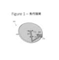
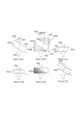
図1に示すように、SATCOMのための放物型反射鏡アンテナ101は、少なくとも、成形された金属片または導電性材料による放物面形状の反射鏡103と、反射鏡103に給電または照射を行う役割を果たすホーンアンテナ109と、これらの構成要素を正確な相対的位置に取り付け、アセンブリ全体を衛星に堅固に向けるように固定する支持構造105、107とを有する。ホーンの口を覆うレードームまたはカバー111は、水またはデブリの侵入からホーンを保護する。いくつかのアンテナは、主反射鏡の照射をより良好に制御し、及び/または、主反射鏡の形状を変化させるために、ビーム経路内に追加の成形または放物型副反射鏡を含む。Ku及びKaによるDTHのための非常にコストの小さいアンテナは、最も典型的には、フィードホーンによって引き起こされる妨害を低減するオフセット給電反射鏡を使用する。フィードホーンは、一般的には、低ノイズブロック(Low-Noise Block, LNB)ダウンコンバータ回路113、ならびに、LNB及びフィードを支持する取付けアームと高度に一体化される。反射鏡及び給電アセンブリの向きが調整され、次いで、ボルトまたは他の締結具によって定位置でロックされることを可能にする柱または壁取り付け固定具が、反射鏡の後部に含まれる。 As shown in FIG. 1, a
放送または双方向衛星サービスの新規加入者は、アンテナ101を購入するか、または、サービスの一部としてアンテナ101の提供を受ける。加入者自身によって設置及び方向付けが可能であると広告されることがあるものの、ほぼ例外なくサービス提供者によって設置が行われている。 New subscribers to broadcast or two-way satellite services purchase
反射鏡103は、おそらく堅固な構造物に取り付けられ、定位置で安全にロックされるが、依然として、風、雪、または他の事象によって定位置から外れる可能性がある。この問題を是正するには、トラックロール(顧客出張サービス)が必要であり、これは、アンテナを正確に方向付けし直すために、訓練を受けた技術者及びツールを送ることを意味する。サービス訪問が行われるということは、たとえ問題の解決に数分しかかからない場合であっても、サービス提供者にとって多大な費用がかかることを意味する。 Although the
アンテナが複数のレシーバに対して予め方向付けられて構成されていない場合にいずれの衛星が接続されるかを変更するには、知識、ツール、及び技能のいずれもが必要である。現在、衛星アンテナを方向付ける方法に関する指示を提供するスマートフォンアプリ及びウェブサイトが存在するが、加入者の大部分は、自らそれを行うことに関心がない。このような理由から、サービス提供者は、自身の加入者基盤によって特定の軌道スロットにロックされ、放送提供者が成功するほど、サービス提供者が自身のサービスの提供元である衛星を提供または変更しようとするときに、サービス提供者が有する柔軟性が低くなる。 Knowledge, tools, and skill are both required to change which satellite is connected when the antenna is not pre-pointed and configured to multiple receivers. Currently, there are smartphone apps and websites that provide instructions on how to aim the satellite dish, but the majority of subscribers are not interested in doing so themselves. For this reason, service providers are locked into specific orbital slots by their own subscriber bases, and the more successful a broadcast provider is, the more likely it is that the service provider will provide or change the satellites from which it provides its services. Service providers have less flexibility when trying to do so.
アンテナの放射パターンまたは方向を制御するために、誘電体、メタマテリアル、またはメタサーフェスから構成されるマイクロ波レンズ及びプリズムが一般に使用されている。マイクロ波レンズは、光学レンズと同じ原理を用いるが、光学波長ではなく無線周波数(高周波)について望ましい特性を有する材料を使用する。特徴及び方法によって利点が異なる。典型的にはマイクロ波レンズ内に4分の1波長板またはレンズの上のコーティングとして実装される反射防止コーティングが一般的に使用されているが、普遍的ではない。反射防止コーティングは、自由空間からレンズ材料内へと進行する信号のインピーダンス整合を改善し、再び、レンズを出る信号のインピーダンス整合を改善する役割を果たす。良好な反射防止コーティングに必要な低誘電率を達成することが困難であることに起因して、発泡体、テクスチャ表面、及び3D印刷の使用を含む、そのようなレンズを構築する多くの方法が存在する。 Microwave lenses and prisms composed of dielectrics, metamaterials, or metasurfaces are commonly used to control the radiation pattern or direction of antennas. Microwave lenses use the same principles as optical lenses, but use materials that have desirable properties for radio frequencies (high frequencies) rather than optical wavelengths. Different features and methods have different advantages. Antireflection coatings, typically implemented as quarter wave plates or coatings on the lenses within microwave lenses, are commonly used, but not universally. Antireflection coatings serve to improve the impedance match of signals traveling from free space into the lens material, and again to improve the impedance match of signals exiting the lens. Due to the difficulty in achieving the low dielectric constant required for good anti-reflection coatings, many methods of constructing such lenses have been proposed, including the use of foams, textured surfaces, and 3D printing. exist.
ビームシフタは、光学において一般的なデバイスであり、ガラスのスラブとしても説明できる研磨平行板プリズムから構成される。入射光ビームに対して様々な角度に回転されると、プリズムからの光の出射点が、光の入射角及びプリズムの厚さに関係する距離だけ横方向にシフトする。そのようなデバイスは、光学反射防止コーティングを含み、システムの複数の部品を位置合わせするための光学調整点及びレーザワークベンチとして使用される。典型例は、Thorlabs XYT/M-A Post-Mountable Tweaker Plate、2.5mm厚(光学ビームシフタ)、thorlabs.comである。 A beam shifter is a common device in optics and consists of a polished parallel plate prism, which can also be described as a slab of glass. When rotated to different angles relative to the incident light beam, the exit point of the light from the prism shifts laterally by a distance that is related to the angle of incidence of the light and the thickness of the prism. Such devices include optical anti-reflection coatings and are used as optical alignment points and laser workbenches for aligning multiple components of a system. A typical example is Thorlabs XYT/M-A Post-Mountable Tweaker Plate, 2.5 mm thick (optical beam shifter), thorlabs.com.
反射鏡アンテナとともに使用するための反射鏡アンテナ方向変更デバイスである。反射鏡アンテナ方向変更デバイスは、入力場を受けて出力場を提供するマイクロ波プリズムを有する。デバイスはまた、プリズムを反射鏡アンテナに接続するように構成されている取り付け構造も有する。また、デバイスは、反射鏡アンテナに対するマイクロ波プリズムの調整可能な位置及び調整可能な向きを設定するための、取り付け構造にある調整可能位置合わせ機構を有し、位置合わせ機構は、入力場に対する出力場の横方向シフトを規定する。 A reflector antenna redirecting device for use with a reflector antenna. A reflector antenna redirecting device has a microwave prism that receives an input field and provides an output field. The device also has a mounting structure configured to connect the prism to the reflector antenna. The device also has an adjustable alignment feature in the mounting structure for setting the adjustable position and adjustable orientation of the microwave prism relative to the reflector antenna, the alignment feature providing an output relative to the input field. Defines the lateral shift of the field.
図面に示す例示的な非限定的実施形態を説明するにあたって、明確にするために特定の用語を用いる。しかし、本開示は、そのように選択された特定の用語に限定することを意図するものではなく、各特定の用語が、同様の目的を達成するために同様に動作するすべての技術的等価物を含むことを理解されたい。いくつかの実施形態が例示を目的として説明されており、本明細書及び特許請求の範囲が、例示されている実施形態に限定されず、図面に具体的に示されていない他の実施形態も、本開示の範囲内にあり得ることは理解されたい。 In describing the exemplary non-limiting embodiments illustrated in the drawings, specific terminology is used for the sake of clarity. However, this disclosure is not intended to be limited to the specific terms so selected, and all technical equivalents of each specific term operate similarly to accomplish a similar purpose. should be understood to include Several embodiments have been described for purposes of illustration, and the specification and claims are not limited to the illustrated embodiments, as well as other embodiments not specifically shown in the drawings. , may be within the scope of this disclosure.
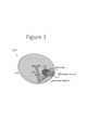
図面を参照すると、図3に、反射鏡方向変更デバイス201を有する反射鏡アンテナ200を示す。反射鏡方向変更デバイス201は、反射鏡アンテナ200の主ビームが、方向変更デバイス201が設置されていないアンテナ200の元の角度に対して、固定の決められた角度だけステアリングされることを可能にする。反射鏡方向変更デバイス201は、デバイス自体によって制御される位置及び向きで、反射鏡のフィードホーン109の上に設置される。 Referring to the drawings, FIG. 3 shows a
当該位置及び向きは、特定の衛星213をすでに指している所与の地理的ロケーション内の反射鏡アンテナ200について(図2(a))、反射鏡方向変更デバイスが設けられることにより、反射鏡103またはフィードホーン109を物理的に動かすことなく、アンテナが代わりに特定の別の衛星215を向くものとなるように設定される。複数のデバイス201、または、同じデバイス201の複数の向きが、公称角度から±10度の範囲内の走査を可能にすることができる。これはハードリミットではないが、さらなる走査の結果、反射鏡方向変更デバイスが設置されていない公称の事例に比べて、より著しく性能が低下する。特定の例として、ワシントンDCの(たとえば)50マイル以内に位置し、50°Wにある衛星から信号を受信するように構成されているアンテナ200は、フィード109の上での5度のシフトのために特別に設計されたデバイス201を設置することによる熟練を要する設置または指向の較正を要することなく、代わりに45°Wにある衛星から信号を受信できるように向きを変えることができる。 The position and orientation is such that for a
便宜上、以下の節は、信号及び場を、アンテナ及び反射鏡から1つのまたは別の衛星に向けて送信されるものとして記述する。衛星からの送信及びアンテナによる受信の往復挙動は記述されないが、記述されている事例に正確に類似する。 For convenience, the following sections describe signals and fields as being transmitted from antennas and reflectors towards one satellite or another. The round trip behavior of transmission from the satellite and reception by the antenna is not described, but exactly resembles the described case.
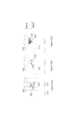
図2(a)に示すように、ホーンアンテナ109は、通常の動作において、ホーンの開口が放物型反射鏡103の焦点203に位置するように設けられる。図2(a)に示す典型的な動作において、システム101は、ホーンからの信号またはアンテナ場205が反射鏡103と相互作用し、所望の目標衛星213に向けられ、ビーム207が形成されるように、方向付けられる。図2(b)に示すように、別の衛星215に向けたビーム211を形成するためのシステム101のステアリングは、アンテナ101全体の方向を変更することによって行うことができるが、フィードホーン109を反射鏡103の焦点203からシフトさせることによって行うこともできる。このとき、オフセットホーンからのアンテナ場209は、反射鏡103と相互作用して、別の衛星215に向けられたビーム211を形成する。しかし、アンテナ101全体の方向を変更すること、または、ホーン109を物理的に動かすことは、両方とも熟練作業者が反射鏡の設計における動きを実施するとともにサポートすることを必要とし、いずれも、ほとんどの事例において組み込み動作としてのツールを用いることなく容易に実施することはできない。 As shown in FIG. 2(a), the
図2(c)、図3に示すように、元々はビーム207を元の衛星213に向けていた場205を横方向にシフトして、代わりに別の衛星215においてビーム211を生成するために、反射鏡方向変更デバイス201が、反射鏡103の焦点203においてホーン109に追加される。ここで、横方向シフトは、フィード支持アームの方向でもある、放物型反射鏡の対称軸に垂直な方向を示す。横方向シフトは、水平、垂直、または両方の組合せであってもよいが、明確な位相中心がほぼ反射鏡103の焦点面上にあり続けることを保証するために、反射鏡軸に垂直な元のフィード開口と位置合わせされた平面内に留まるべきである。フィード開口のロケーションが、すべてのシフトの比較の開始点を定める。場の角度の横方向シフト及び場合によって補正は、実効的に、反射鏡103を、ホーン109が別の位置にあるかのように挙動させ、したがって、新たな所望の方向においてビーム211を生成させる。 2(c), to laterally shift the
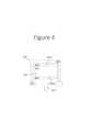
次に図4に示すように、反射鏡方向変更デバイス201は、一方または両方の表面(図4の実施形態では上面及び底面)に必要に応じて反射防止コーティング機構403を有するマイクロ波プリズムまたはプリズム401と、プリズムをホストホーン109に接続し、固定するように構成されている取付けシステムまたは機構407と、それらの要素を保護するためのレードームまたは他のカバー405とを有する。マイクロ波プリズム、プリズム、マイクロ波レンズ、及びレンズという用語はすべて、デバイス401に適用されるように意図されており、プリズムという用語は、本開示においてはマイクロ波プリズムを含むものとして用いる。 4, the
マイクロ波プリズムの構成は、実践及び原理において、GRINレンズを含むマイクロ波レンズの構成と多くの類似点を有する。プリズムは、ビーム、または円錐、ビーム、もしくは電磁エネルギーの他の分布を屈曲またはシフトさせることを主な目的とした屈折素子を意味する。その一方で、レンズは、円錐、ビームまたは電磁エネルギーの他の分布を拡張または収縮させることを主な目的とした屈折素子を意味する。プリズムを、エネルギーを集中させるように設計することもでき、レンズを、エネルギーを屈曲させるように設計することもできるため、これら2つの概念の間に厳密な区別はない。本開示の場合、デバイス401の主な目的は、拡張または収縮ではなく、エネルギーを屈曲及びシフトさせることであるため、プリズムがより有意義であると考えられるが、何らかの拡張及び収縮も含まれてよい。 The construction of microwave prisms has many similarities in practice and principle to the construction of microwave lenses, including GRIN lenses. Prism means a refractive element whose primary purpose is to bend or shift a beam or cone, beam, or other distribution of electromagnetic energy. A lens, on the other hand, means a refractive element whose primary purpose is to expand or contract a cone, beam or other distribution of electromagnetic energy. There is no strict distinction between these two concepts, as prisms can be designed to concentrate energy and lenses can be designed to bend energy. For the purposes of this disclosure, a prism would make more sense since the primary purpose of the
プリズム401及び取付け機構407は、特定の型またはモデルの反射鏡アンテナ101及び付随するホーン109に特有のものであり、特定の衛星213、215にも特有のものである。取付け機構407は、たとえば、締結具(ボルト、ナット、ねじなど)、または接着剤であってもよい。 The
図4に示すように、1つの実施形態において、マイクロ波プリズム401は、第1のプリズム表面402aと、第1の表面402aとは反対側にある第2のプリズム表面402bとを有する本体402を備えている。プリズム本体402は、上面、底面、及び少なくとも1つの側面を有し、円形、正方形、または長方形などの任意の適切な形状の断面を有することができる。第1のプリズム面402aは本体402の上面にあり、第2のプリズム表面402bは本体402の底面にある。第1のプリズム表面402a及び第2のプリズム表面402bは平面である。反射防止コーティング機構403は、第1のプリズム表面402a及び第2のプリズム表面402bに施されたコーティングとすることができる。1つの実施形態において、反射防止コーティング機構はコーティング上面及びコーティング底面を有し、第1のコーティング機構403aはプリズム本体402のプリズム上面402aに接するコーティング底面を有し、第2のコーティング機構403bはプリズム本体402のプリズム底面402bに接するコーティング上面を有する。 As shown in FIG. 4, in one
図4の実施形態において、プリズムは平行板プリズムである。第1のプリズム表面402aは、第2のプリズム表面402bに平行である。加えて、ホーン109の広がった側が前方開口を形成し、広がった側の前縁が平面的な前方周縁を形成する。ホーン109は、ホーンの後部からホーンの前部へと延びる中心長手方向軸をも有する。第1のプリズム表面402a及び第2のプリズム表面402bは、ホーン109の平面的な口部に略平行であり、ホーン109の長手方向軸に直交する。 In the embodiment of Figure 4, the prism is a parallel plate prism. The
1つの実施形態において、ホーン109及び反射鏡方向変更デバイス201は、代わりに、フレームまたはハウジングなどの共通の支持体に接続することができ、取付けシステムまたは機構407は、反射鏡方向変更デバイス201を、ホーン109ではなく支持体に接続することができる。 In one embodiment, the
プリズム401は、取付け機構407によって強制される、特定の向きにおいてホーンアンテナ109の開口の近くにまたは開口に位置決めされることにより機能する。図5において、プリズム401は、適切に位置決めがされると、プリズム401がない場合のホーン109からのアンテナ場の元の、または乱されていない場の位置506に対して、デバイスを出入りする入力場及び出力場505の対応する位置において横方向オフセット507を生成する。
フィードホーンから発するアンテナ場は、レーザから来るものと同じように高度にコリメートされているわけではなく(レーザ光の短波長と比較してマイクロ波の波長がはるかにより長いため)、代わりに、場は、フィードホーン109と反射鏡103との間で球状または円錐状に広がっている。したがって、レーザとマイクロ波との間の斯かる差に起因して、反射鏡方向変更デバイス201は、光学のための単純な平面ビームシフタとは異なり、ホーンから到来するエネルギーの円錐形状の発散を可能にするための補正を含むことができる。たとえば、反射鏡方向変更デバイス201は、ゼロでない光出力が、方向変更デバイス201から出る出力場の像面湾曲及び実効的な位相中心の軸方向位置を補正するための非平坦面(特に、プリズム底面402b及び/またはプリズム上面402a)を有することができる。 The antenna field emanating from a feedhorn is not as highly collimated as that coming from a laser (due to the much longer wavelength of microwaves compared to the short wavelength of laser light), but instead extends spherically or conically between
プリズム401の中核的な動作は、場をホーン109のロケーションに比べて横方向にシフトさせることである。それは、任意の適切な方法で実施することができ、そのいくつかの例を、反射鏡方向変更デバイス201の様々な構成として、図5(a)~図5(f)の実施形態に示し説明する。 The core action of
図5(a)に示すように、最も単純な選択肢は、マイクロ波プリズム401を、均一な高い誘電率で形成される光学ビームシフタまたは平行板プリズム401aとして構成することである。プリズム401は、ホーンアンテナ109に対して規定の角度に保持され、より具体的には、第1の表面402a及び/または第2の表面402bが、ホーン109の開口の平面に対して或る角度、及び、ホーン109の中心長手方向軸に対して或る角度にある。これは、必要に応じて、より高い性能を支持するための反射防止層403を含んでもよい。しかし、大きい横方向シフトまたはオフセット507を生成するためには、この実施形態は、プリズムが非常に厚くなり、場の高い入射角(伝達効率を制限する)、及び、大きい誘電率εを有することを必要とし得る。これらの要因が重なり合って、プリズムオプション401aが大きくなり、重くなる。 The simplest option is to construct the
図5(b)に示すように、別のプリズム401bは、1つまたは複数のウェッジ508からなる系列によって構造全体を通じて信号の方向をより円滑に変更するための結合及び反射防止層を含む。プリズム401bは、プリズム401aのように、平行な形状を有する中央の本体またはプレート502を有し、1つまたは複数のウェッジ508は、中央プレート502の上部及び/または底部から外向きに延び、中央の本体に(たとえば接着剤により)接続されるか、または、中央本体と一体的に形成される。1つまたは複数のウェッジからなる第1のセット508aは本体502の第1の側面(上面)に配置され、1つまたは複数のウェッジからなる第2のセット508bは本体502の第2の側面(底面)に配置される。 As shown in FIG. 5(b), another
ウェッジ508は、任意の適切な形状を有してもよい。しかし、図示されている実施形態において、各ウェッジ508は、略三角形の形状であり、本体502に面する第1の主平面と、本体502とは反対側を向いた第2の主平面と、小さい副表面とを有する。ウェッジの第1のセット508aのうちの一番下のウェッジの底面は、本体502の上面502aに接し、各ウェッジの上面は、隣接するウェッジの底面に接している。ウェッジの第2のセット508bのうちの一番上のウェッジの上面は、本体502の底面502bに接し、各ウェッジの底面は、隣接するウェッジの上面に接している。 Wedge 508 may have any suitable shape. However, in the illustrated embodiment, each wedge 508 is generally triangular in shape, with a first major
各ウェッジは、第1の主表面と第2の主表面との間に形成された鋭角を有する。1つの実施形態において、ウェッジの第1のセット508aは、ホーン109の口の平面に対する本体502の底面402bのオフセット角θと同じとすることができる複合的な角を有する。また、ウェッジの第2のセット508bは、ホーン109の口の平面に対する本体502の上面402aのオフセット角θと同じとすることができる複合的な角を有する。したがって、下側のウェッジセットの一番下のウェッジ508bの底部ウェッジ表面は、ホーン口の平面に、そして、上部ウェッジセットの一番上のウェッジ508aの上部ウェッジ表面に略平行である。したがって、上部ウェッジセット508aの鋭角は、本体502の一辺(すなわち、図5(b)の実施形態の左側)に位置合わせされ、底部ウェッジセット508bの鋭角は、本体502の反対側の辺(すなわち右側)に位置合わせされる。この構成において、信号は元の信号軸506に略平行に、オフセットされて伝わり、これはまた、中心ホーン長手方向軸にも平行であり得る。 Each wedge has an acute angle formed between the first major surface and the second major surface. In one embodiment, the first set of
1つの実施形態において、各ウェッジ508の複数の誘電体層ε1、ε2、ε3、ε4、及びε5は、中心プレート502から遠ざかるにつれて誘電率が連続的に大きくなっており、ε1が最も小さく、ε5が最も大きい。すなわち、中心プレート502は最も高い誘電率を有し、中心プレート502からの隣接する各ウェッジ508は、誘電率が連続的に小さくなる。この設計は、層の数が増加し、各層における場の入射角がはるかに小さくなることによって、伝達効率が増大することを可能にするが、設計のサイズ及び質量を最小限に抑えることには、ほとんど効果がない。したがって、各ウェッジ508は信号を屈折させる。また、底部ウェッジセット508bの各ウェッジ508は、元の軸506に対する信号の角度を増分的に増大させる。また、信号が元の軸506と略平行になるか、または、他の様態で元の軸506に対して所望の角度になるまで、上部ウェッジセット508aの各ウェッジ508は、元の軸506に対する信号の角度を減少させる。上部ウェッジ506aの上面及び底部ウェッジ506bの底面に、反射防止コーティング403を配置してもよい。 In one embodiment, the plurality of dielectric layers ε1, ε2, ε3, ε4, and ε5 of each wedge 508 have continuously increasing dielectric constants away from the
図5(c)に、送信アレイの概念も含み得る、メタマテリアル及びメタサーフェス技術によるプリズム401cを示す。この実施形態は、必要な材料の量を減らすことによってプリズム401cの質量が低減するが、それに応じて動作帯域幅が低減し、挿入損失が増大する。特性が誘電率及び形状によって規定される、かさばる誘電体を使用するのではなく、メタサーフェスのプリズムが、支持構造によって空中に懸架されているメタマテリアルまたはメタサーフェスの1つまたは複数の層を有する。この実施態様について、プリズム401cは、送信される場に位相勾配を導入することによって、2つの点においてホーン109からの場の方向を変化させる、空間的に変化するメタマテリアルまたはメタサーフェスの2つの層531、535から構成することができる。メタマテリアルまたはメタサーフェスのプリズムは、従来のプリズムのように、誘電体領域内の屈折に依拠せず、401a及び401bに含まれる誘電体領域を含まない。したがって、底部メタマテリアルまたはメタサーフェス531は、信号を元の信号軸506から外方に屈折させ、その結果、信号は、元の信号軸506に対して或る角度で進行する。また、上部メタマテリアルまたはメタサーフェス535は、信号を、元の信号軸506に平行になるように戻して屈折させる。二重屈折により、信号が元の信号軸506からオフセットされ、またそれに平行にオフセットされる。 Fig. 5(c) shows a
2つの層531、535の間の間隙または分離は、場が伝播し横方向オフセットを生成するための距離をとるために必要とされる。分離が大きいほど、横方向オフセットは大きくなる。分離は、層531、535の間の空間を空隙として維持する、プリズム構造の内部の機械的構造533によって維持される。たとえば、機械的構造533は、支持体または梁とすることができ、層531、535の一方または両方は、それらの間に所望の空隙距離を維持する異なる位置において支持体に接続することができる。プリズムの内部のこの支持構造は、目的及び実施態様が、プリズム401をフィード109に対して保持する構造407とは別個であり、2つの層531と535との間の固定間隔を維持するために、支持体、ボルト、クリップ、または他の物理的機構を使用して実装することができる。層531及び535を形成する人工誘電体またはメタサーフェス構造は、表面にわたって位相勾配を設定し、したがって、ビームをステアリングし、それによって設計の使用可能な帯域幅を制限するために、各層531及び535の表面にわたってそれらの構造を周期的に変化させることを必要とする。メタマテリアルまたはメタサーフェス設計は、多くの場合、狭帯域で損失が大きいが、一部の用途にとっては十分であり得る。両方の層を通じた伝達効率は、このスタイルの実施態様にとって重要なメトリックである。 A gap or separation between the two
図5(d)に、構造の厚さを低減する波形プリズム401dを示す。これによって、ひいては支持構造407及びレードーム405もより小さくすることができるため、重量が低減する。401a及び401bに示すプリズムの大きな高さも、プリズム401dの上面及び底面に成形された波形を導入することにより減少する。波形は、鋸歯型形状を有する。左から、上面の各歯は、ホーンの長手方向軸に略平行で真っ直ぐな前方立ち上がりエッジを有し、続いて角度のついた後方立ち下がりエッジを有する。 FIG. 5(d) shows a
プリズム401dは、プリズム401aを畳んだようなバージョンを示すが、同じ手法を多層401bに適用してもよい。上面及び底面401dにフレネル型の波形を使用することによってプリズムのサイズ及び形状を潰すことによって、ほぼ同じビームステアリング特性を維持することができるが、プリズムの高さが減少する。これによって、動作帯域幅が制限されるが、メタサーフェス/メタマテリアル手法よりも分散が小さい可能性が高い分散効果が生まれる。401dの波形上面及び底面に、波形自体の形状に合わせて反射防止コーティングを施してもよい。底面は、信号を屈折させて元の信号軸506に対して或る角度を生じさせ、上面は、信号を元の信号軸506に平行になるように(かつ、元の信号軸506からオフセットされるように)戻して屈折させる。
図5(e)において、内部誘電率ε(x,y,z)を完全に制御できる勾配型屈折率(屈折率分布型)の、すなわち不均一なプリズム401eが、最小の可能な連続パッケージに機能性を倒れ込ませるという多大な利点を提供する。円滑に変化する(連続的な)勾配設計と、段階的な勾配設計との両方における課題は、必要な性能を達成するのに必要な、複雑であることが多い形状及び構造を作製することである。 In FIG. 5(e), a graded index (gradient index) or
図5(f)に、2つのハーフプリズム401fを示す。プリズム401の質量は方向変更デバイス201の設計の主要因子であるため、プリズムの内部にある誘電体の領域が不要なときは除去され、或る距離または空隙の分だけ互いに分離されている2つのハーフプリズム401fが実効的に形成されるプリズムを含む、プリズムの質量を低減するための他の措置をとることができる。いくつかの実施態様において、この間隙は、他の部分は中実のプリズム内に構築され得る中空領域として実装されてもよく、重量が低減されるが、支持体533と同様の別個の取り付けまたは支持構造を必要としない。ハーフプリズム401fは、平坦なまたは湾曲した表面を有する三角形状とすることができる。図示のように、上側ハーフプリズムは、わずかに凹状になるように湾曲した内向きの表面を有することができ、下側ハーフプリズムは、わずかに凸状になるように湾曲した内向きの表面を有することができる。上側ハーフプリズムの内向きの表面は、下側ハーフプリズムの内向きの表面に面し、それと嵌合する形状を有する。プリズムの内面のプロファイルが、各角度において場の伝播方向に一致することによって、場が、除かれた材料が依然としてそこにあるかのように、界面において屈折することなく、真っ直ぐであり続けることが可能になる。この質量低減の手法はまた、利用可能な誘電体の損失正接が空気に比べて高い場合にも有用である。下側ハーフプリズム401fの底面は、ホーン口の平面に対して角度θを成し、元の信号軸506に対して或る角度になるように信号を屈折させる。下側ハーフプリズム401fの上面は、信号をさらに屈折させる。上側ハーフプリズム401fの底面は、信号を元の信号軸506に平行になるように戻して屈折させ、上側ハーフプリズム401fの上面は、信号を元の信号軸506に平行になるように、かつ、元の信号軸506からオフセットされるようにさらに屈折させる。上側ハーフプリズムと下側ハーフプリズム401fとの間の距離が大きいほど、元の信号軸506からの信号の達成可能な横方向オフセットが大きくなる。 FIG. 5(f) shows two
誘電体領域を通じて伝播する場は、それらが空気のみを通じて伝播した場合ほど大きく拡張しないため、デバイス201から到来する場の実効的な位相中心はもはや、反射鏡に一致し得ない。横方向位置が正確であり得る場合であっても、反射鏡までのフィード分布の位相中心の距離は、開口効率を維持するために、依然として反射鏡の焦点距離に一致する必要がある。非ゼロ光学利得の包含(表面の湾曲または内部誘電体勾配を通じた)を使用して、場の角度分布と実効的な位相中心の両方を補正することができる。 Since fields propagating through dielectric regions do not expand as much as if they propagated through air alone, the effective phase center of the fields coming from
プリズム401の必要なサイズは、場に必要な横方向シフトの度合い及び反射鏡の幾何学的形状によってともに決定される。良好なプリズムは、コストを最小限に抑え、設置を単純にするために、小型、軽量、かつコンパクトであるべきである。しかし、プリズム401は、フィードホーンからの出力のすべてをインターセプトし、そのエネルギーをすべて反射鏡へと方向を変更できるようなサイズにしなければならない。 The required size of
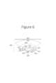
図6に示すように、小さいf/D(焦点距離603対直径605)比、または同等に広い照射円錐角609を有する反射鏡について、特定の厚さの特定のプリズム611の実施態様は、プリズムの基部においてホーンからの元の放射パターン円錐631をカバーするのに十分に、横方向を大きくし、中心合わせし直された円錐633の表面全体にわたってエネルギーを放出するためにプリズム611の出口において十分に大きくし、所望の経路607に従うのに十分にエネルギーを再成形するのに十分な内部厚さ615及び幅613を可能にしなければならない。より厚い(625)プリズム621の実施態様が、必要な横方向シフトを提供するために必要とされる場合(一般に、さらなるシフトは、伝播するより大きい余地を提供するためにより厚いプリズムを必要とする)、プリズムはまた(少なくとも出力において)、より広く(623)しなければならず、したがって、プリズムの体積及び質量が、(一般に概ね)プリズムの厚さの3乗に比例するようにしなければならない。これによって、質量も制御するように、他の性能パラメータを達成しながらプリズム厚さを最小限に抑えるための必須の要件がもたらされる。 As shown in FIG. 6, for a reflector with a small f/D (
f/D比はまた、反射鏡を所与の角度へとステアリングするのに必要な横方向シフトの量にも影響を与える。f/D比が低い反射鏡は、多くの一般的な消費者向けDTHアンテナのように、ビーム走査角度のより大きいシフトを生成するために、実効的なフィード位置109の小さい変化を可能にする。f/Dが高い反射鏡は、円錐角が小さいため、所与の距離だけ開口場をシフトさせるのに必要なプリズムがより小さくなるが、度単位の主ビームの同じ走査角度を得るためにより大きい物理的シフトが必要になる。 The f/D ratio also affects the amount of lateral shift required to steer the reflector to a given angle. Low f/D ratio reflectors allow small changes in
1つの実施形態において、反射鏡方向変更デバイス201は、既存のホーンアンテナに組み込まれる(また、締結具メカニズム、接着剤などを用いて接続される)。したがって、これは、既存のホーンアンテナ及び放物型反射鏡とともに動作するように構成されている。プリズム401の特性は、アンテナシステム101を適合させるように設計されている。しかし、他の実施形態において、ホーンアンテナ及び放物型反射鏡は、デバイス201を容易かつ精密に設置する準備が整っている取付け機構407、偏りなくデバイス201の追加の重量を支持するための強力な取付けアーム107(図1)、及び、システム201全体の質量を最適化するのに十分に大きいf/D比を含め、デバイス201とともに動作するように設計することができる。 In one embodiment, the
衛星の所与のペア、すなわち、現在使用されている衛星213及び新たな目標衛星215について(図2)、反射鏡方向変更デバイス201によって適用されなければならない補正角、及び、オフセットが適用されるべきである現在のアンテナ指示方向に対する方向は、2つの衛星間の角度距離、及び、衛星が観察される地球上のロケーションに基づく。 For a given pair of satellites, namely the currently used
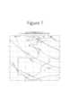
図7に、適用されなければならない地上の差分角度を示す。DTHに使用される相対的に直径の小さい反射鏡103(典型的には40~80cmの間)は、相当に広いビームを有するため、補正の分解能は非常に粗い。反射鏡方向変更デバイス201の目標設置ロケーションに基づいて、図7のものと同様の地図が参照され、必要な補正角及び方向が選択される。次いで、補正角及び方向が、各組合せの独立したプリズム及び取り付け設計における実施態様によって適用され、調整可能な固定具または取り付け構成によって、より広い地理的領域に対して単一のプリズム及び固定具設計を適切に使用して、走査角度及び方向が設定される。プリズムは、結果としてもたらされるビームがシステム200のロケーションに基づいて目標衛星を指すようにするために、ホーンアンテナ109の中心軸を中心として補正角だけ実効的に回転される。プリズムまたは設定選択は、デバイスをエンドユーザに出荷する前に実施することができ、または、エンドユーザに、ユーザのロケーションに応じた特定の番号またはラベルを付された設定を使用するための指示を提供することができる。すなわち、指示は、「あなたの郵便番号ABCについては、取り付けクリップを、あなたのアンテナに設置する前に、矢印が位置Dに合うように回転させてください」とすることができる。 FIG. 7 shows the differential angles on the ground that must be applied. The relatively small diameter mirror 103 (typically between 40-80 cm) used for DTH has a fairly wide beam, so the resolution of the correction is very coarse. Based on the target installation location of the
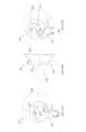
これらの指示は、図8(a)及び図8(b)に示す実施態様に適用される。中心が点811にあるように取り付けられたホーンアンテナ109が示されている。プリズム401(例示のみを目的として示されているが、デバイス201のレードーム405内に含まれる)は、ホーンの場を、プリズムを出て点813へと中心合わせし直されるようにシフトさせる。戻り止め及び位置合わせマーキングのセットが、エンドユーザによって、または、出荷前に調整可能に位置合わせされるように、外側ハウジングまたはレードーム材料上に設けられる。位置合わせマーキングは、ユーザが、反射鏡アンテナに対する、特に、ホーンフィード109に対するマイクロ波プリズムの調整可能な位置及び調整可能な向きを設定するために、取り付け構造を調整することを可能にする。すなわち、取り付け構造407は、デバイス201をアンテナ101に固定的に、ただし、調整可能型位置合わせマーキングによって規定される位置及び向きにおいて取り付ける。位置合わせ機構は、取り付け構造に対するマイクロ波プリズムの複数の位置及び向きを規定し、地理的ロケーションに基づいて工場において設定することができる。したがって、エンドユーザは、設置ロケーションの地理的ロケーションに基づいて(図7の地図を使用することなどにより)、適切な設定を決定することができる。 These instructions apply to the embodiment shown in FIGS. 8(a) and 8(b).
フィードホーン109の中心軸に対するプリズム401の向きを変化させると、元の取り付けられたアンテナに対する再ステアリングされたビームの角度が変化する。たとえば、プリズムは、フィードホーン109の中心軸を中心として回転することができ、それによって、結果としてもたらされるビームが元のビーム方向の東または西に向けられるとともに、所望の衛星215を正確に指すために水平線の上でビームが向けられる仰角が調整される。プリズム401を動かすために、1つまたは複数の支持部材または締結部材を提供することができる。たとえば、締結部材は、プリズム401をレードーム405または取り付け構造407に可動に接続することができ、結果として、プリズム401は、フィードホーン109に対する向きを変えることができる。 Changing the orientation of
図8(c)に、位置Aに位置合わせされたデバイス401を示す一方、図8(a)に、位置Eに位置合わせされたデバイス401を示す。ここで、ホーンから発する信号は、図5(a)~図5(f)に示すように、プリズムからオフセットされることに留意されたい。アラインメント817は、プリズム401に接続することができ、結果、アラインメント817を様々な位置の間で回転させることによってプリズム401全体も回転する。プリズム及びアラインメント817が位置Eにあるとき(図8(a))、プリズムの位相中心813は、ホーンの位相中心811からオフセットされている。より具体的には、プリズムの位相中心813は、ホーンの位相中心811に対して約2時方向にある。プリズム及びアラインメント817が位置Aにあるとき(図8(c))、プリズムの位相中心813は、ホーンの位相中心811に対して概ね4時方向にある。したがって、アラインメントが回転すると、プリズムの位相中心813が回転し、これによって、プリズムによって出力される信号が動く。別の実施形態において、アラインメントの異なる位置が、プリズムの異なる角度を生成し得る。 8(c) shows the
プリズム401は、図4~図6において前述したような、任意の形状、または、フィードホーンに対する様々な向きのいずれかをとることができ、次いで、レードームの形状及び境界はプリズムを適切にカバーするように選択される。
調整可能型アラインメント817を位置合わせした後、デバイスは、任意の適切な方法でホーンに固定的に接続する。たとえば、取付けシステム407は、アンテナの取り付けバーへとスナップ嵌めされ、ホーンシュラウド815によって安定化及び方向付けされるスナップコネクタ819を含むことができる。設置されると、デバイスは、この時点で、反射鏡に、その主ビームを新たな所望の衛星215に向かせる。取付け機構407は、さもなければ反射鏡103に達するホーン109からの場のすべてをインターセプトするために適切な位置にデバイスを固定的に保持し、反射鏡アンテナ101の走査角の変化をもたらすために、場を横方向にシフトさせる。このとき、アンテナ101及びデバイス201の適切な動作中に、さらなる運動または活動は必要ない。アンテナが再び元の現在使用されている衛星213に方向変更されることが求められる場合、デバイス201は、取り付け機構819を取り外すことによって除くことができる。 After aligning
図面は例示であり得、本明細書及び特許請求の範囲は、右、左、上方、下方、上側、下側、側方、上部、底部、細長い、平行、横方向、直交、角度、長方形、正方形、円形、丸みを帯びた、軸などの、幾何学的または関係用語を使用することができることに留意されたい。これらの用語は、本開示を限定するようには意図されておらず、一般に、図面に示されている例に基づいて説明を容易にする便宜のために使用される。加えて、幾何学的または関係用語は、正確でなくてもよい。たとえば、信号及び平面は、互いに対して正確に垂直または平行でない場合があるが、依然として垂直または平行であると考えられてもよい。 The drawings may be exemplary and the specification and claims herein may include: right, left, upper, lower, upper, lower, lateral, upper, bottom, elongated, parallel, transverse, orthogonal, angular, rectangular, Note that geometric or relational terms such as square, circular, rounded, axis, etc. can be used. These terms are not intended to limit the disclosure and are generally used for convenience in facilitating explanation based on the examples shown in the drawings. Additionally, the geometric or relational terminology may not be exact. For example, the signal and plane may not be exactly perpendicular or parallel to each other, but may still be considered perpendicular or parallel.
上記の説明及び図面は、本開示の原理の例示に過ぎないと考えられるべきである。システムは、様々な形状及びサイズに構成されてもよく、実施形態によって制限されるようには意図されていない。システムの多数の応用形態が、当業者には容易に着想される。したがって、本開示を、開示されている具体例、または、図示及び説明されている正確な構造及び動作に限定することは所望されない。むしろ、本開示の範囲内に入る、すべての適切な変更及び均等物が依拠され得る。
The above description and drawings should be considered as illustrative only of the principles of the disclosure. The system may be configured in various shapes and sizes and is not intended to be limited by embodiment. Numerous applications of the system will readily occur to those skilled in the art. Therefore, it is not desired to limit the present disclosure to the specific examples disclosed or the precise structure and operation shown and described. Rather, all suitable modifications and equivalents falling within the scope of this disclosure can be relied upon.
Claims (18)
Translated fromJapanese前記プリズムを反射鏡アンテナに接続する取付け構造と、
前記取付け構造に設けられ、前記反射鏡アンテナに対する前記マイクロ波プリズムの位置及び向きを設定し、前記入力場に対する前記出力場のシフトを定める位置合わせ機構と
を備える、反射鏡アンテナとともに使用される反射鏡アンテナ方向変更デバイス。a microwave prism that receives an input field and provides an output field;
a mounting structure for connecting the prism to a reflector antenna;
an alignment mechanism on the mounting structure for setting the position and orientation of the microwave prism with respect to the reflector antenna and for defining the shift of the output field with respect to the input field. Mirror antenna redirection device.
前記複数の位置は、地理的ロケーションに基づいて工場にて設定される、
請求項1から13のいずれか1項に記載のデバイス。the alignment mechanism is adjustable to define multiple positions and orientations of the microwave prism relative to the mounting structure;
wherein the plurality of positions are factory set based on geographic location;
14. A device according to any one of claims 1-13.
前記アンテナ場を受けて出力場を提供するマイクロ波プリズムと、
前記ホーンアンテナに対して前記マイクロ波プリズムの位置を定める取付け構造と、
前記ホーンアンテナに対する前記マイクロ波プリズムの複数の調整可能な位置を定める調整可能型位置合わせ機構であって、前記複数の調整可能な位置の各々は、前記アンテナ場に対する前記出力場のシフトをそれぞれ定めるものである、調整可能型位置合わせ機構と
を備える反射鏡アンテナ。a horn antenna providing an antenna field;
a microwave prism that receives the antenna field and provides an output field;
a mounting structure that positions the microwave prism with respect to the horn antenna;
An adjustable alignment mechanism defining a plurality of adjustable positions of the microwave prism relative to the horn antenna, each of the plurality of adjustable positions respectively defining a shift of the output field relative to the antenna field. A reflector antenna comprising: an adjustable alignment mechanism of
18. The device of Claim 16 or 17, further comprising a radome covering said microwave prism.
Applications Claiming Priority (3)
| Application Number | Priority Date | Filing Date | Title |
|---|---|---|---|
| US202062981367P | 2020-02-25 | 2020-02-25 | |
| US62/981,367 | 2020-02-25 | ||
| PCT/IB2021/051453WO2021171157A1 (en) | 2020-02-25 | 2021-02-19 | Prism for repointing reflector antenna main beam |
Publications (2)
| Publication Number | Publication Date |
|---|---|
| JP2023514436Atrue JP2023514436A (en) | 2023-04-05 |
| JP7724225B2 JP7724225B2 (en) | 2025-08-15 |
Family
ID=75267529
Family Applications (1)
| Application Number | Title | Priority Date | Filing Date |
|---|---|---|---|
| JP2022550797AActiveJP7724225B2 (en) | 2020-02-25 | 2021-02-19 | A prism for redirecting the main beam of a reflector antenna |
Country Status (10)
| Country | Link |
|---|---|
| US (3) | US11469515B2 (en) |
| EP (1) | EP4111531A1 (en) |
| JP (1) | JP7724225B2 (en) |
| CN (1) | CN115315848A (en) |
| AU (1) | AU2021227766A1 (en) |
| BR (1) | BR112022016560A2 (en) |
| CA (1) | CA3170825A1 (en) |
| MX (1) | MX2022010547A (en) |
| WO (1) | WO2021171157A1 (en) |
| ZA (1) | ZA202210213B (en) |
Families Citing this family (2)
| Publication number | Priority date | Publication date | Assignee | Title |
|---|---|---|---|---|
| BR112022016560A2 (en)* | 2020-02-25 | 2023-01-10 | All Space Networks Ltd | PRISM TO REDIRECT MAIN BEAM OF REFLECTOR ANTENNA |
| CN114914701B (en)* | 2022-05-12 | 2024-10-15 | 中国人民解放军空军工程大学 | Beam reconfigurable origami spatially ordered gradient phase metasurface and its design method |
Citations (7)
| Publication number | Priority date | Publication date | Assignee | Title |
|---|---|---|---|---|
| JPH04328480A (en)* | 1991-04-30 | 1992-11-17 | Robotec Kenkyusho:Kk | Scanning beam antenna system apparatus |
| JP2006145399A (en)* | 2004-11-19 | 2006-06-08 | Matsushita Electric Ind Co Ltd | Automotive radar equipment |
| JP2006166399A (en)* | 2004-11-15 | 2006-06-22 | Maspro Denkoh Corp | Antenna system for emc test, test signal generation apparatus and transmission apparatus |
| US20080238811A1 (en)* | 2007-03-30 | 2008-10-02 | Robert Scott Winsor | Method and Apparatus for Steering Radio Frequency Beams Utilizing Photonic Crystal Structures |
| JP2009050005A (en)* | 2007-08-20 | 2009-03-05 | Itt Manufacturing Enterprises Inc | Method and apparatus for steering and stabilizing radio-frequency beam using photonic crystal structure |
| US20150048963A1 (en)* | 2013-08-14 | 2015-02-19 | Vega Grieshaber Kg | Radar beam deflection unit for a radar level indicator |
| WO2017182612A1 (en)* | 2016-04-22 | 2017-10-26 | Thales | System for deflecting and pointing a microwave beam |
Family Cites Families (61)
| Publication number | Priority date | Publication date | Assignee | Title |
|---|---|---|---|---|
| US4333082A (en)* | 1980-03-31 | 1982-06-01 | Sperry Corporation | Inhomogeneous dielectric dome antenna |
| US4531129A (en) | 1983-03-01 | 1985-07-23 | Cubic Corporation | Multiple-feed luneberg lens scanning antenna system |
| GB8717845D0 (en) | 1987-07-28 | 1987-09-03 | Univ London | Refracting elements |
| ES2090604T3 (en) | 1991-01-28 | 1996-10-16 | Thomson Multimedia Sa | ANTENNA SYSTEM. |
| US5736959A (en) | 1991-10-28 | 1998-04-07 | Teledesic Corporation | Earth-fixed cell beam management for satellite communication system using dielectic lens-focused scanning beam antennas |
| CA2157139A1 (en) | 1994-09-01 | 1996-03-02 | Thomas C. Weakley | Multiple beam antenna system for simultaneously receiving multiple satellite signals |
| US6121939A (en) | 1996-11-15 | 2000-09-19 | Yagi Antenna Co., Ltd. | Multibeam antenna |
| US6075497A (en) | 1997-06-30 | 2000-06-13 | Acer Neweb Corp. | Multiple-feed electromagnetic signal receiving apparatus |
| US6181293B1 (en) | 1998-01-08 | 2001-01-30 | E*Star, Inc. | Reflector based dielectric lens antenna system including bifocal lens |
| US6160520A (en) | 1998-01-08 | 2000-12-12 | E★Star, Inc. | Distributed bifocal abbe-sine for wide-angle multi-beam and scanning antenna system |
| US6107897A (en) | 1998-01-08 | 2000-08-22 | E*Star, Inc. | Orthogonal mode junction (OMJ) for use in antenna system |
| US6218853B1 (en) | 1998-12-11 | 2001-04-17 | Daniel Liu | Circuit arrangement for simulating alternating current load |
| CN2370427Y (en)* | 1999-02-12 | 2000-03-22 | 中国科学院紫金山天文台 | Wave beam modulator |
| US6593893B2 (en) | 2000-03-06 | 2003-07-15 | Hughes Electronics Corporation | Multiple-beam antenna employing dielectric filled feeds for multiple and closely spaced satellites |
| US6710749B2 (en) | 2000-03-15 | 2004-03-23 | King Controls | Satellite locator system |
| SE522925C2 (en) | 2001-03-08 | 2004-03-16 | Telewide Ab | Receiving signals from multiple satellites in a single antenna |
| US6512485B2 (en) | 2001-03-12 | 2003-01-28 | Wildblue Communications, Inc. | Multi-band antenna for bundled broadband satellite internet access and DBS television service |
| EP1437796B1 (en) | 2001-09-28 | 2006-10-25 | Sumitomo Electric Industries, Ltd. | Radio wave lens antenna apparatus |
| AU2002308745A1 (en) | 2002-05-16 | 2003-12-02 | Ems Technologies, Inc. | Scanning directional antenna with lens and reflector assembly |
| CN1682402B (en) | 2002-08-20 | 2010-09-29 | 爱罗莎特股份有限公司 | Communication system with broadband antenna |
| WO2004068636A1 (en) | 2003-01-30 | 2004-08-12 | Sumitomo Electric Industries, Ltd. | Lens antenna system |
| JP2004304737A (en) | 2003-04-01 | 2004-10-28 | Seiko Epson Corp | Antenna device and method of manufacturing the same |
| CN1768451B (en) | 2003-04-02 | 2011-01-26 | 住友电气工业株式会社 | Radio wave lens antenna equipment |
| US7236681B2 (en) | 2003-09-25 | 2007-06-26 | Prodelin Corporation | Feed assembly for multi-beam antenna with non-circular reflector, and such an assembly that is field-switchable between linear and circular polarization modes |
| EP1745526A4 (en) | 2004-03-11 | 2008-03-19 | Intellian Technologies Inc | Satellite tracking antenna system and method therefor |
| US7342551B2 (en) | 2004-04-13 | 2008-03-11 | Electronic Controlled Systems | Antenna systems for reliable satellite television reception in moisture conditions |
| US20050280593A1 (en) | 2004-06-22 | 2005-12-22 | Seung-Hyeon Cha | Satellite tracking antenna and method using rotation of a subreflector |
| US7522115B2 (en) | 2004-07-13 | 2009-04-21 | Mediaur Technologies, Inc. | Satellite ground station antenna with wide field of view and nulling pattern using surface waveguide antennas |
| US7511677B2 (en) | 2004-07-13 | 2009-03-31 | Mediaur Technologies, Inc. | Satellite ground station antenna with wide field of view and nulling pattern |
| US7526249B2 (en) | 2004-07-13 | 2009-04-28 | Mediaur Technologies, Inc. | Satellite ground station to receive signals with different polarization modes |
| US7375698B2 (en) | 2005-12-02 | 2008-05-20 | Andrew Corporation | Hydrophobic feed window |
| US7656345B2 (en)* | 2006-06-13 | 2010-02-02 | Ball Aerospace & Technoloiges Corp. | Low-profile lens method and apparatus for mechanical steering of aperture antennas |
| KR101354151B1 (en) | 2006-08-24 | 2014-01-28 | 삼성전자주식회사 | Method and apparatus for transforming and inverse-transforming image |
| GB2442796A (en) | 2006-10-11 | 2008-04-16 | John Thornton | Hemispherical lens with a selective reflective planar surface for a multi-beam antenna |
| US8604989B1 (en) | 2006-11-22 | 2013-12-10 | Randall B. Olsen | Steerable antenna |
| US8982004B1 (en) | 2007-08-03 | 2015-03-17 | The Directv Group, Inc. | Integrated ODU controller for antenna pointing |
| GB0810075D0 (en) | 2008-05-03 | 2008-07-09 | Raven Mfg Ltd | Satellite date receiving apparatus |
| US7982687B1 (en) | 2008-10-02 | 2011-07-19 | The Directv Group, Inc. | Ka/Ku outdoor unit configuration using a frequency selective surface |
| WO2011014919A1 (en) | 2009-08-04 | 2011-02-10 | Bae Systems Australia Limited | A multi-band antenna |
| WO2011087538A2 (en) | 2009-10-22 | 2011-07-21 | Lockheed Martin Corporation | Metamaterial lens feed for multiple beam antennas |
| US20110109501A1 (en) | 2009-11-06 | 2011-05-12 | Viasat, Inc. | Automated beam peaking satellite ground terminal |
| US20160079682A1 (en) | 2010-07-30 | 2016-03-17 | Spatial Digital Systems, Inc. | Polarization Re-alignment for Mobile Satellite Terminals |
| TWI449445B (en) | 2010-10-07 | 2014-08-11 | Wistron Neweb Corp | Beamwidth adjustment device |
| EP2684248B1 (en) | 2011-03-09 | 2019-05-01 | Thrane & Thrane A/S | Device for switching between linear and circular polarization using a rotatable depolarizer |
| WO2012129240A2 (en)* | 2011-03-20 | 2012-09-27 | Viasat, Inc. | Manually repointable satellite antenna |
| EP2715869B1 (en) | 2011-05-23 | 2018-04-18 | Limited Liability Company "Radio Gigabit" | Electronically beam steerable antenna device |
| US8810468B2 (en)* | 2011-06-27 | 2014-08-19 | Raytheon Company | Beam shaping of RF feed energy for reflector-based antennas |
| WO2014193257A1 (en) | 2013-05-27 | 2014-12-04 | Limited Liability Company "Radio Gigabit" | Lens antenna |
| KR101477199B1 (en) | 2013-07-03 | 2014-12-29 | (주)인텔리안테크놀로지스 | Satellite receiving/transmitting anttena having structure for switching multiple band signal |
| US20150116155A1 (en) | 2013-10-25 | 2015-04-30 | The Charles Stark Draper Laboratory, Inc. | Methods and systems for self-aligning high data rate communication networks |
| US9722316B2 (en) | 2014-07-07 | 2017-08-01 | Google Inc. | Horn lens antenna |
| US10122085B2 (en) | 2014-12-15 | 2018-11-06 | The Boeing Company | Feed re-pointing technique for multiple shaped beams reflector antennas |
| US9577327B2 (en) | 2015-07-20 | 2017-02-21 | Elwha Llc | Electromagnetic beam steering antenna |
| US9620855B2 (en) | 2015-07-20 | 2017-04-11 | Elwha Llc | Electromagnetic beam steering antenna |
| US10553943B2 (en) | 2015-09-22 | 2020-02-04 | Qualcomm Incorporated | Low-cost satellite user terminal antenna |
| US10158177B2 (en) | 2016-03-11 | 2018-12-18 | Scott Cook | Antenna horn with suspended dielectric tuning vane |
| WO2018017518A2 (en) | 2016-07-21 | 2018-01-25 | Astronics Aerosat Corporation | Multi-channel communications antenna |
| US10116051B2 (en) | 2017-03-17 | 2018-10-30 | Isotropic Systems Ltd. | Lens antenna system |
| US10530054B2 (en)* | 2017-11-01 | 2020-01-07 | Searete Llc | Aperture efficiency enhancements using holographic and quasi-optical beam shaping lenses |
| CN113131224B (en)* | 2020-01-16 | 2022-08-19 | 华为技术有限公司 | Antenna beam propagation direction adjustment system |
| BR112022016560A2 (en)* | 2020-02-25 | 2023-01-10 | All Space Networks Ltd | PRISM TO REDIRECT MAIN BEAM OF REFLECTOR ANTENNA |
- 2021
- 2021-02-19BRBR112022016560Apatent/BR112022016560A2/enunknown
- 2021-02-19AUAU2021227766Apatent/AU2021227766A1/enactivePending
- 2021-02-19CNCN202180016990.6Apatent/CN115315848A/enactivePending
- 2021-02-19MXMX2022010547Apatent/MX2022010547A/enunknown
- 2021-02-19JPJP2022550797Apatent/JP7724225B2/enactiveActive
- 2021-02-19CACA3170825Apatent/CA3170825A1/enactivePending
- 2021-02-19EPEP21714943.4Apatent/EP4111531A1/enactivePending
- 2021-02-19WOPCT/IB2021/051453patent/WO2021171157A1/ennot_activeCeased
- 2021-02-23USUS17/182,992patent/US11469515B2/enactiveActive
- 2022
- 2022-09-13USUS17/943,895patent/US11888228B2/enactiveActive
- 2022-09-14ZAZA2022/10213Apatent/ZA202210213B/enunknown
- 2023
- 2023-12-12USUS18/536,580patent/US20240128655A1/enactivePending
Patent Citations (7)
| Publication number | Priority date | Publication date | Assignee | Title |
|---|---|---|---|---|
| JPH04328480A (en)* | 1991-04-30 | 1992-11-17 | Robotec Kenkyusho:Kk | Scanning beam antenna system apparatus |
| JP2006166399A (en)* | 2004-11-15 | 2006-06-22 | Maspro Denkoh Corp | Antenna system for emc test, test signal generation apparatus and transmission apparatus |
| JP2006145399A (en)* | 2004-11-19 | 2006-06-08 | Matsushita Electric Ind Co Ltd | Automotive radar equipment |
| US20080238811A1 (en)* | 2007-03-30 | 2008-10-02 | Robert Scott Winsor | Method and Apparatus for Steering Radio Frequency Beams Utilizing Photonic Crystal Structures |
| JP2009050005A (en)* | 2007-08-20 | 2009-03-05 | Itt Manufacturing Enterprises Inc | Method and apparatus for steering and stabilizing radio-frequency beam using photonic crystal structure |
| US20150048963A1 (en)* | 2013-08-14 | 2015-02-19 | Vega Grieshaber Kg | Radar beam deflection unit for a radar level indicator |
| WO2017182612A1 (en)* | 2016-04-22 | 2017-10-26 | Thales | System for deflecting and pointing a microwave beam |
Also Published As
| Publication number | Publication date |
|---|---|
| CA3170825A1 (en) | 2021-09-02 |
| US20230006358A1 (en) | 2023-01-05 |
| US11469515B2 (en) | 2022-10-11 |
| WO2021171157A1 (en) | 2021-09-02 |
| MX2022010547A (en) | 2022-11-16 |
| ZA202210213B (en) | 2025-01-29 |
| EP4111531A1 (en) | 2023-01-04 |
| JP7724225B2 (en) | 2025-08-15 |
| AU2021227766A1 (en) | 2022-09-01 |
| US20240128655A1 (en) | 2024-04-18 |
| US11888228B2 (en) | 2024-01-30 |
| US20210265739A1 (en) | 2021-08-26 |
| BR112022016560A2 (en) | 2023-01-10 |
| CN115315848A (en) | 2022-11-08 |
Similar Documents
| Publication | Publication Date | Title |
|---|---|---|
| US20240128655A1 (en) | Prism for repointing reflector antenna main beam | |
| US6204822B1 (en) | Multibeam satellite communication antenna | |
| US8497810B2 (en) | Multi-band antenna system for satellite communications | |
| US5929819A (en) | Flat antenna for satellite communication | |
| US6211842B1 (en) | Antenna with continuous reflector for multiple reception of satelite beams | |
| US11258172B2 (en) | Multi-beam shaped reflector antenna for concurrent communication with multiple satellites | |
| US7227501B2 (en) | Compensating structures and reflector antenna systems employing the same | |
| US6747604B2 (en) | Steerable offset antenna with fixed feed source | |
| US7154439B2 (en) | Communication satellite cellular coverage pointing correction using uplink beacon signal | |
| WO1999038228A1 (en) | Multi-primary radiator, down converter and multibeam antenna | |
| US6172649B1 (en) | Antenna with high scanning capacity | |
| JPH1197924A (en) | Antenna system | |
| RU2807961C1 (en) | Low profile composite satellite antenna | |
| JPS6251808A (en) | satellite receiving antenna equipment | |
| JP2594137B2 (en) | Multi-beam antenna | |
| JPH0481106A (en) | Antenna system | |
| Gonzalo et al. | Space Antennas including Terahertz Antennas | |
| AU7242700A (en) | Multibeam satellite communication antenna | |
| JPH01277007A (en) | Antenna system |
Legal Events
| Date | Code | Title | Description |
|---|---|---|---|
| A621 | Written request for application examination | Free format text:JAPANESE INTERMEDIATE CODE: A621 Effective date:20240123 | |
| A977 | Report on retrieval | Free format text:JAPANESE INTERMEDIATE CODE: A971007 Effective date:20241213 | |
| A131 | Notification of reasons for refusal | Free format text:JAPANESE INTERMEDIATE CODE: A131 Effective date:20241224 | |
| A601 | Written request for extension of time | Free format text:JAPANESE INTERMEDIATE CODE: A601 Effective date:20250314 | |
| A601 | Written request for extension of time | Free format text:JAPANESE INTERMEDIATE CODE: A601 Effective date:20250521 | |
| A521 | Request for written amendment filed | Free format text:JAPANESE INTERMEDIATE CODE: A523 Effective date:20250620 | |
| TRDD | Decision of grant or rejection written | ||
| A01 | Written decision to grant a patent or to grant a registration (utility model) | Free format text:JAPANESE INTERMEDIATE CODE: A01 Effective date:20250704 | |
| A61 | First payment of annual fees (during grant procedure) | Free format text:JAPANESE INTERMEDIATE CODE: A61 Effective date:20250804 | |
| R150 | Certificate of patent or registration of utility model | Ref document number:7724225 Country of ref document:JP Free format text:JAPANESE INTERMEDIATE CODE: R150 |