JP2023513034A - intravascular blood pump - Google Patents
intravascular blood pumpDownload PDFInfo
- Publication number
- JP2023513034A JP2023513034AJP2022546353AJP2022546353AJP2023513034AJP 2023513034 AJP2023513034 AJP 2023513034AJP 2022546353 AJP2022546353 AJP 2022546353AJP 2022546353 AJP2022546353 AJP 2022546353AJP 2023513034 AJP2023513034 AJP 2023513034A
- Authority
- JP
- Japan
- Prior art keywords
- rotor
- blood pump
- intravascular blood
- distal end
- housing
- Prior art date
- Legal status (The legal status is an assumption and is not a legal conclusion. Google has not performed a legal analysis and makes no representation as to the accuracy of the status listed.)
- Granted
Links
Images


Classifications
- A—HUMAN NECESSITIES
- A61—MEDICAL OR VETERINARY SCIENCE; HYGIENE
- A61M—DEVICES FOR INTRODUCING MEDIA INTO, OR ONTO, THE BODY; DEVICES FOR TRANSDUCING BODY MEDIA OR FOR TAKING MEDIA FROM THE BODY; DEVICES FOR PRODUCING OR ENDING SLEEP OR STUPOR
- A61M60/00—Blood pumps; Devices for mechanical circulatory actuation; Balloon pumps for circulatory assistance
- A61M60/10—Location thereof with respect to the patient's body
- A61M60/122—Implantable pumps or pumping devices, i.e. the blood being pumped inside the patient's body
- A61M60/126—Implantable pumps or pumping devices, i.e. the blood being pumped inside the patient's body implantable via, into, inside, in line, branching on, or around a blood vessel
- A61M60/13—Implantable pumps or pumping devices, i.e. the blood being pumped inside the patient's body implantable via, into, inside, in line, branching on, or around a blood vessel by means of a catheter allowing explantation, e.g. catheter pumps temporarily introduced via the vascular system
- A—HUMAN NECESSITIES
- A61—MEDICAL OR VETERINARY SCIENCE; HYGIENE
- A61M—DEVICES FOR INTRODUCING MEDIA INTO, OR ONTO, THE BODY; DEVICES FOR TRANSDUCING BODY MEDIA OR FOR TAKING MEDIA FROM THE BODY; DEVICES FOR PRODUCING OR ENDING SLEEP OR STUPOR
- A61M60/00—Blood pumps; Devices for mechanical circulatory actuation; Balloon pumps for circulatory assistance
- A61M60/20—Type thereof
- A61M60/205—Non-positive displacement blood pumps
- A61M60/216—Non-positive displacement blood pumps including a rotating member acting on the blood, e.g. impeller
- A—HUMAN NECESSITIES
- A61—MEDICAL OR VETERINARY SCIENCE; HYGIENE
- A61M—DEVICES FOR INTRODUCING MEDIA INTO, OR ONTO, THE BODY; DEVICES FOR TRANSDUCING BODY MEDIA OR FOR TAKING MEDIA FROM THE BODY; DEVICES FOR PRODUCING OR ENDING SLEEP OR STUPOR
- A61M60/00—Blood pumps; Devices for mechanical circulatory actuation; Balloon pumps for circulatory assistance
- A61M60/40—Details relating to driving
- A61M60/403—Details relating to driving for non-positive displacement blood pumps
- A61M60/408—Details relating to driving for non-positive displacement blood pumps the force acting on the blood contacting member being mechanical, e.g. transmitted by a shaft or cable
- A61M60/411—Details relating to driving for non-positive displacement blood pumps the force acting on the blood contacting member being mechanical, e.g. transmitted by a shaft or cable generated by an electromotor
- A61M60/414—Details relating to driving for non-positive displacement blood pumps the force acting on the blood contacting member being mechanical, e.g. transmitted by a shaft or cable generated by an electromotor transmitted by a rotating cable, e.g. for blood pumps mounted on a catheter
- A—HUMAN NECESSITIES
- A61—MEDICAL OR VETERINARY SCIENCE; HYGIENE
- A61M—DEVICES FOR INTRODUCING MEDIA INTO, OR ONTO, THE BODY; DEVICES FOR TRANSDUCING BODY MEDIA OR FOR TAKING MEDIA FROM THE BODY; DEVICES FOR PRODUCING OR ENDING SLEEP OR STUPOR
- A61M60/00—Blood pumps; Devices for mechanical circulatory actuation; Balloon pumps for circulatory assistance
- A61M60/80—Constructional details other than related to driving
- A61M60/802—Constructional details other than related to driving of non-positive displacement blood pumps
- A61M60/804—Impellers
- A61M60/806—Vanes or blades
- A61M60/808—Vanes or blades specially adapted for deformable impellers, e.g. expandable impellers
- A—HUMAN NECESSITIES
- A61—MEDICAL OR VETERINARY SCIENCE; HYGIENE
- A61M—DEVICES FOR INTRODUCING MEDIA INTO, OR ONTO, THE BODY; DEVICES FOR TRANSDUCING BODY MEDIA OR FOR TAKING MEDIA FROM THE BODY; DEVICES FOR PRODUCING OR ENDING SLEEP OR STUPOR
- A61M60/00—Blood pumps; Devices for mechanical circulatory actuation; Balloon pumps for circulatory assistance
- A61M60/80—Constructional details other than related to driving
- A61M60/802—Constructional details other than related to driving of non-positive displacement blood pumps
- A61M60/818—Bearings
- A61M60/825—Contact bearings, e.g. ball-and-cup or pivot bearings
Landscapes
- Health & Medical Sciences (AREA)
- Heart & Thoracic Surgery (AREA)
- Engineering & Computer Science (AREA)
- Life Sciences & Earth Sciences (AREA)
- Mechanical Engineering (AREA)
- Anesthesiology (AREA)
- Biomedical Technology (AREA)
- Hematology (AREA)
- Cardiology (AREA)
- Animal Behavior & Ethology (AREA)
- General Health & Medical Sciences (AREA)
- Public Health (AREA)
- Veterinary Medicine (AREA)
- Vascular Medicine (AREA)
- External Artificial Organs (AREA)
- Massaging Devices (AREA)
Abstract
Translated fromJapanese
Description
Translated fromJapanese本発明は、ヒトまたは任意選択的にさらに動物における血液循環を支援するための、血管内血液ポンプ、詳細には、経皮的に挿入可能な血液ポンプに関する。例えば、血液ポンプは、例えば、心臓のポンプ作用を支援するため、またはこれに取って代わるために、患者の大腿動脈内に経皮的に挿入され、患者の血管系を通じて誘導されるように設計され得る。 The present invention relates to intravascular blood pumps, in particular percutaneously insertable blood pumps, for supporting blood circulation in humans or optionally also in animals. For example, blood pumps are designed to be percutaneously inserted into a patient's femoral artery and navigated through the patient's vascular system, e.g., to assist in or replace the pumping action of the heart. can be
本発明は、長く可撓性の高い駆動軸を介して体外モータによって駆動される拡張可能なロータが収容される拡張可能なハウジングを有する血管内血液ポンプの文脈において説明されるが、本発明は、モータがロータの隣に患者の身体の内側に位置する、および/またはハウジングおよびロータが拡張可能ではない他のタイプの血管内血液ポンプにも適用可能である。 Although the invention will be described in the context of an intravascular blood pump having an expandable housing containing an expandable rotor driven by an extracorporeal motor via a long, highly flexible drive shaft, the invention is , where the motor is located inside the patient's body next to the rotor, and/or where the housing and rotor are not expandable.
先に述べた拡張可能なタイプの血液ポンプは、例えば、カテーテルポンプアセンブリを開示する米国第2013/0303969 A1号から知られている。拡張可能なハウジングは、カテーテルの遠位端に位置する。拡張可能なハウジングは、カテーテルの第1の内腔を通って延びる可撓性の高い駆動軸によって駆動される拡張可能なロータを囲む。カテーテルポンプアセンブリの遠位部分は、例えば、セルディンガー技術を使用して、経皮アクセスを介して心臓の内側に置かれ得る。駆動軸は、中央内腔を含み、これは、ガイドワイヤがそのガイドと一緒に駆動軸を通過すること可能にし、心臓の内側へのカテーテルポンプアセンブリの正確な位置付けを可能にする。ロータは、カテーテルの端に、およびロータの近位に配置される軸受内に回転可能に支持される。カテーテルは、血液が軸受に入って詰まることを防ぐために、パージ流体を遠位方向に運搬して少なくともそのような軸受をパージするための第2の内腔を備える。本明細書では、「近位」および「遠位」は、医師に対して見たものである。故に、カテーテルが置かれるとき、近位は、医師に比較的近いものを指す一方、遠位は、医師から比較的遠くに離れているものを指す。 A blood pump of the previously mentioned expandable type is known, for example, from US 2013/0303969 A1, which discloses a catheter pump assembly. An expandable housing is located at the distal end of the catheter. An expandable housing encloses an expandable rotor driven by a highly flexible drive shaft extending through the first lumen of the catheter. The distal portion of the catheter pump assembly may be placed inside the heart via percutaneous access using, for example, the Seldinger technique. The drive shaft includes a central lumen that allows a guidewire along with its guide to pass through the drive shaft to allow precise positioning of the catheter pump assembly inside the heart. The rotor is rotatably supported at the end of the catheter and within bearings located proximally of the rotor. The catheter includes a second lumen for conveying a purge fluid distally to purge at least such bearings to prevent blood from entering and clogging the bearings. As used herein, "proximal" and "distal" are what the physician sees. Thus, when the catheter is placed, proximal refers to what is relatively close to the physician, while distal refers to what is relatively far from the physician.
文書米国特許第2013/0303970 A1号は、同様に、近位ならびに遠位軸受を備える拡張可能なカテーテルポンプアセンブリについて説明する。ロータは、近位軸受と遠位軸受との間の駆動軸に取り付けられる。遠位軸受は、静止した拡張可能な遠位軸受支持体によって適所に保持され、この遠位軸受支持体は、ハウジングがその拡張した状態にあるとき、ハウジングと摺動可能に接触状態にある。遠位軸受支持体は、ガイドワイヤおよびそのガイドが通過することを可能にする自己シール型セプタムを備える。ガイドワイヤおよびそのガイドがカテーテルポンプアセンブリから除去されるとき、セプタムは再封止し、故に、血液が駆動軸へ入ることを防ぐ。 Document US2013/0303970 A1 similarly describes an expandable catheter pump assembly with proximal and distal bearings. A rotor is mounted on the drive shaft between the proximal and distal bearings. The distal bearing is held in place by a stationary expandable distal bearing support that is in slidable contact with the housing when the housing is in its expanded state. The distal bearing support includes a self-sealing septum that allows passage of the guidewire and its guide. When the guidewire and its guide are removed from the catheter pump assembly, the septum reseals, thus preventing blood from entering the drive shaft.
遠位軸受の1つの利点は、ロータ羽根とハウジングの内面との間の隙間が、大きい直径を有するロータが採用されるときにさえ血管損傷を回避するためにより良好に制御され得ることである。他の配置において、駆動軸の遠位端は、ハウジングの遠位端に配置される遠位軸受内に取り付けられる。しかしながら、ロータから遠位に遠位軸受内に支持される駆動軸を伴う血管内血液ポンプは、心臓の腱構造体がハウジング内へ引き込まれ、駆動軸の周りに絡まるという問題を有する。これは、心臓構造体の破壊ならびに血管内血液ポンプへの損傷、および血塊が遠位軸受に生じるリスクの増大をもたらし得る。 One advantage of the distal bearing is that the clearance between the rotor blades and the inner surface of the housing can be better controlled to avoid vascular injury even when rotors with large diameters are employed. In other arrangements, the distal end of the drive shaft is mounted within a distal bearing located at the distal end of the housing. However, intravascular blood pumps with a drive shaft supported in a distal bearing distal from the rotor have the problem that the tendon structures of the heart are drawn into the housing and become entangled around the drive shaft. This can lead to destruction of cardiac structures and damage to the intravascular blood pump and increased risk of clots forming in the distal bearing.
回転部品と組織の絡まりを回避するため、欧州特許第2047873 A1号は、ポリウレタン駆動軸カバーおよび回転軸を血液から離す軸受-ハブ群について説明する。しかしながら、通常、隙間およびハブの回転部分が残っているため、回転軸はその周囲に露出される。これは、心臓の腱構造体が、その隙間内またはハブの遠位部分に引っかかる場合があり、それが患者の負傷および血管内血液ポンプへの損傷をもたらし得ることから、問題である。 To avoid tangling of rotating parts and tissue, EP2047873A1 describes a polyurethane drive shaft cover and a bearing-hub group that keeps the rotating shaft away from the blood. However, there is usually a gap and a rotating portion of the hub remaining so that the rotating shaft is exposed around it. This is a problem because the tendon structures of the heart can get caught in the gap or distal portion of the hub, which can lead to injury to the patient and damage to the intravascular blood pump.
したがって、心臓の腱構造体がポンプ内で絡む危険性なしに血管内血液ポンプのハウジングの内側でロータを遠位に支持する必要性がある。 Therefore, there is a need to distally support the rotor inside the housing of an intravascular blood pump without risking the tendon structures of the heart becoming entangled within the pump.
本発明の第1の態様によると、血管内血液ポンプは、ポンピングデバイスおよびカテーテルを備える。ポンピングデバイスは、駆動軸と、駆動軸の遠位端に位置し、ハウジングに収容されるロータと、ロータの遠位端を回転可能に支持するための少なくとも遠位軸受とを備える。さらには、本明細書に開示される血液ポンプにおいて、遠位軸受は、ロータの遠位端内へ、またはこれに直面して突き出る静的支持部材を備える。 According to a first aspect of the invention, an intravascular blood pump comprises a pumping device and a catheter. The pumping device includes a drive shaft, a rotor located at a distal end of the drive shaft and housed in a housing, and at least a distal bearing for rotatably supporting the distal end of the rotor. Additionally, in the blood pumps disclosed herein, the distal bearing comprises a static support member projecting into or against the distal end of the rotor.
したがって、駆動軸が遠位軸受内で支持されるのではなく、代わりに、ロータは、ロータ内へ、またはこれに直面して延びる静的支持部材によって支持されるのがロータの遠位端となるように、駆動軸の最も端に取り付けられる。このようにすると、腱構造体は、特に、回転する円筒構造体が回転羽根の最先端を超えて延びない場合、回転部品に引っかかる可能性が低い。これは、より長い寿命を有するより安全な血管内血液ポンプをもたらす。 Thus, rather than the drive shaft being supported in a distal bearing, the rotor is instead supported by a static support member extending into or facing the rotor at its distal end. It is attached to the extreme end of the drive shaft so that In this way, the tendon structure is less likely to catch on rotating parts, especially if the rotating cylindrical structure does not extend beyond the tip of the rotating vane. This results in a safer intravascular blood pump with a longer lifespan.
駆動軸が体外電気モータによって駆動される実施形態において、駆動軸は、好ましくは、カテーテルの近位端領域からカテーテルの遠位端領域へ延びる。駆動軸は、典型的には、可撓性が高く、好ましくは中空である。駆動軸は、好ましくは、異なって配向されたファイバ層で好ましくは形成される可撓性の高いケーブルからなるか、またはこれを備える。特に、駆動軸ケーブルは、最も好ましくは、駆動軸に沿って軸方向に延びる内腔の周りにらせん状に走る、好ましくは異なる巻き方向、特に好ましくは交互の巻き方向を有する複数の同軸巻き線で構成される。例えば、駆動軸ケーブルは、反対の巻き方向を有する2つの同軸巻き線を備えることができ、駆動軸ケーブルの外径は、0.4mm~2mm、好ましくは、0.6mm~1.2mm、特に好ましくは、0.8mm~1.0mmであり得る。駆動軸ケーブルの近位端は、好ましくは、体外電気モータに装着される。駆動軸ケーブルは、電気モータから駆動軸の遠位端にあるロータへトルクを伝達する役割を果たす。場合によっては、駆動軸ケーブルは、ロータに安定性を提供するために、その遠位端に堅く剛性の高い軸を備えてもよく、その軸上に、ロータがハウジングの内側で装着される。 In embodiments in which the drive shaft is driven by an extracorporeal electric motor, the drive shaft preferably extends from the proximal end region of the catheter to the distal end region of the catheter. The drive shaft is typically highly flexible and preferably hollow. The drive shaft preferably consists of or comprises a highly flexible cable preferably formed of differently oriented fiber layers. In particular, the drive shaft cable most preferably comprises a plurality of coaxial windings, preferably having different winding directions, particularly preferably alternating winding directions, running helically around a bore extending axially along the drive shaft. consists of For example, the drive shaft cable may comprise two coaxial windings with opposite winding directions, the outer diameter of the drive shaft cable being between 0.4 mm and 2 mm, preferably between 0.6 mm and 1.2 mm, especially Preferably, it may be between 0.8 mm and 1.0 mm. The proximal end of the drive shaft cable is preferably attached to the extracorporeal electric motor. The drive shaft cable serves to transmit torque from the electric motor to the rotor at the distal end of the drive shaft. Optionally, the drive shaft cable may have a stiff, rigid shaft at its distal end to provide stability to the rotor, on which the rotor is mounted inside the housing.
遠位端領域において、駆動軸は、いくつかの実施形態では、駆動軸に沿って軸方向に延びる内腔内に提供される補強要素、例えば、金属ワイヤまたは炭素線によって補強される。1つの実施形態において、金属ワイヤは、1.4310ステンレス鋼で作製される。 In the distal end region, the drive shaft is reinforced in some embodiments by stiffening elements, such as metal wires or carbon wires, provided within a lumen extending axially along the drive shaft. In one embodiment, the metal wire is made of 1.4310 stainless steel.
血管内血液ポンプは、好ましくは、拡張可能な区域を有するハウジングを伴う拡張可能な血液ポンプとして設計される。いくつかの実施形態において、ハウジングは、形状記憶材料、特にニチノールを含むか、またはこれからなる。経皮的に挿入可能な血液ポンプの直径は、一般的に、横断されることになる最小血管の内径により制限される。血管内血液ポンプは、ハウジングが折りたたみ状態にある状態で血管を通って移動され得る。心臓またはより大きい血管に到達すると、血管内血液ポンプのハウジングは、拡張され得る。これにより、この方法以外で可能なものよりも大きい血液ポンプを心臓内に経皮挿入することが可能になる。そのようなより大きい血液ポンプでは、より多くの血流量を生成させることが可能であり得る。 The intravascular blood pump is preferably designed as an expandable blood pump with a housing having an expandable section. In some embodiments, the housing comprises or consists of a shape memory material, particularly Nitinol. The diameter of a percutaneously insertable blood pump is generally limited by the inner diameter of the smallest blood vessel to be traversed. An intravascular blood pump can be moved through a blood vessel with the housing in a collapsed state. Upon reaching the heart or larger blood vessels, the housing of the intravascular blood pump can be expanded. This allows percutaneous insertion of a larger blood pump into the heart than would otherwise be possible. With such a larger blood pump, it may be possible to generate more blood flow.
血液ポンプが拡張可能なポンプとして設計されるとき、カニューレは、好ましくは、ロータの近位にある駆動軸の一部分の周りに提供され、ハウジングおよびロータは、カニューレ内へ少なくとも部分的に移送されるように構成される。そのような移送の間、ハウジングの拡張可能な区域およびロータは、拡張した状態から圧縮した状態へと、少なくとも、長手方向に対して横方向に延びる径方向に沿って圧縮される。好ましくは、ロータ羽根などのロータの部分、またはロータ全体もまた、より大きいロータが心臓内へ挿入されることを可能にするために拡張可能であり、このことが流量を改善し得る。 When the blood pump is designed as an expandable pump, a cannula is preferably provided around a portion of the drive shaft proximal to the rotor, the housing and rotor being at least partially transferred into the cannula. configured as During such transport, the expandable section of the housing and the rotor are compressed from an expanded state to a compressed state at least along a radial direction extending transversely to the longitudinal direction. Preferably, portions of the rotor, such as rotor blades, or the entire rotor are also expandable to allow a larger rotor to be inserted into the heart, which can improve flow.
いくつかの実施形態において、静的支持部材は、ロータの遠位端に直面して突き出る。静的支持部材がロータ内へ突き出る実施形態と比較して、血管内血液ポンプの特に可撓性の高いポンプ区域が作成され得る。ポンピングデバイスの高い可撓性は、血管内血液ポンプの挿入および除去中に特に有利である。静的支持部材がロータ内に突き出ず、代わりに、単にロータの遠位端に直面して置かれる場合、ポンプ区域が血管を通るポンピングデバイスの操作中に屈曲するとき、ロータから意図的に外れ得る。ポンプ区域が、心臓の内側のその最終目的地に到達するとき、それは、真っすぐになり得、静的支持部材は、それがロータの遠位端に直面して突き出る位置を取り戻し得る。 In some embodiments, the static support member protrudes facing the distal end of the rotor. A particularly flexible pump section of the intravascular blood pump can be created compared to embodiments in which the static support member protrudes into the rotor. The high flexibility of the pumping device is particularly advantageous during insertion and removal of intravascular blood pumps. If the static support member does not protrude into the rotor, but instead is simply placed facing the distal end of the rotor, it is intentionally disengaged from the rotor when the pump section is flexed during operation of the pumping device through a blood vessel. obtain. When the pump section reaches its final destination inside the heart, it may straighten out and the static support member may resume the position where it protrudes facing the distal end of the rotor.
好ましくは、静的支持部材は、ハウジングの遠位端に装着され、ハウジングの拡張は、静的支持部材を介してロータの遠位端上へ軸方向の力を提供し得る。好ましくは、力は、1.8N以下である。静的支持部材がロータの遠位端に直面して突き出るとき、それは、ハウジングのさらなる拡張を制限し得る。 Preferably, the static support member is mounted to the distal end of the housing, and expansion of the housing may provide an axial force onto the distal end of the rotor via the static support member. Preferably, the force is 1.8N or less. When the static support member protrudes facing the distal end of the rotor, it can limit further expansion of the housing.
ハウジングが圧縮されるとき、静的支持部材は、好ましくは、ロータの遠位端から離れる方へ移動する。この状態では、静的支持部材およびロータの相対的な径方向運動が可能になるため、ポンプ区域は、より可撓性が高い。これは、血管内血液ポンプの挿入中または回収中に有利であり得る。 The static support member preferably moves away from the distal end of the rotor when the housing is compressed. In this state, the pump section is more flexible as it allows relative radial movement of the static support member and rotor. This may be advantageous during insertion or withdrawal of the intravascular blood pump.
特定の実施形態において、血管内血液ポンプは、ロータの遠位端においてノーズ部を備える。ハウジングが拡張した状態にあるとき、ノーズ部は、静的支持部材内へ突き出るが、この静的支持部材は、好ましくは、相応して形成された凹部を保有する。ノーズ部は、ロータの回転を中心に置く、ならびにハウジングの拡張後にロータおよび静的支持部材を正しい相対位置にするという目的を有する。ノーズ部は、好ましくは、0.1mm~2mm、より好ましくは、0.2mm~1mm、および最も好ましくは、0.3mm~0.5mmだけ、ロータの周囲面上に突き出る。静的支持部材内の凹部の深さは、ノーズ部に対応し、好ましくは、0.1mm~2mm、より好ましくは、0.2mm~1mm、および最も好ましくは、0.3mm~0.5mmである。 In certain embodiments, an intravascular blood pump comprises a nose at the distal end of the rotor. When the housing is in its expanded state, the nose protrudes into the static support member, which preferably carries a correspondingly shaped recess. The nose has the purpose of centering the rotation of the rotor and of correcting the relative positions of the rotor and the static support member after expansion of the housing. The nose preferably projects above the peripheral surface of the rotor by 0.1 mm to 2 mm, more preferably 0.2 mm to 1 mm, and most preferably 0.3 mm to 0.5 mm. The depth of the recess in the static support member corresponds to the nose, preferably between 0.1 mm and 2 mm, more preferably between 0.2 mm and 1 mm, and most preferably between 0.3 mm and 0.5 mm. be.
静的支持部材がロータ内へ突き出るいくつかの実施形態において、ロータは、底または段を有するその遠位端における凹部など、静的支持部材のための軸方向停止部を備える。底または段は、ロータの遠位端における静的支持部材の近位端のための軸方向停止部を画定する。これは、拡張可能な血液ポンプの文脈において特に有利である。その拡張した状態では、ロータ内へ軸方向に突き出る静的支持部材の近位端は、軸方向停止部と接触状態にあり得、以て、ハウジングのさらなる拡張を防ぎ、および故に、ロータ羽根の外縁と拡張可能なハウジングの内面との間の径方向の隙間幅を制限する。代替的に、拡張可能な血液ポンプの拡張した状態では、静的支持部材の近位端および軸方向停止部は、隙間を形成し得、これは、軸方向に、好ましくは、0.01mm~1mm、より好ましくは、0.01mm~0.1、および最も好ましくは、0.01mm~0.05mmの幅である。 In some embodiments where the static support member protrudes into the rotor, the rotor includes an axial stop for the static support member, such as a recess at its distal end having a bottom or step. A bottom or step defines an axial stop for the proximal end of the static support member at the distal end of the rotor. This is particularly advantageous in the context of expandable blood pumps. In its expanded state, the proximal end of the static support member projecting axially into the rotor may be in contact with the axial stop, thus preventing further expansion of the housing and thus the rotor blades. Limiting the radial gap width between the outer edge and the inner surface of the expandable housing. Alternatively, in the expanded state of the expandable blood pump, the proximal end and axial stop of the static support member may form a gap, which is axially preferably 0.01 mm to 0.01 mm. 1 mm, more preferably 0.01 mm to 0.1, and most preferably 0.01 mm to 0.05 mm wide.
軸方向に測定されるロータの遠位端における凹部の長さは、例えば、0.5mm~8mm、好ましくは、1mm~5mm、特に好ましくは、1.5mm~2.5mmである。ハウジングがカニューレ内へ移動されるとき、ハウジングは、好ましくは、軸方向に0.5mm~2.5mmだけ、より好ましくは、1mm~2mm、最も好ましくは、およそ1.7mmだけ伸びる。 The length of the recess at the distal end of the rotor, measured in the axial direction, is for example 0.5 mm to 8 mm, preferably 1 mm to 5 mm, particularly preferably 1.5 mm to 2.5 mm. When the housing is moved into the cannula, the housing preferably extends axially by 0.5 mm to 2.5 mm, more preferably 1 mm to 2 mm, most preferably approximately 1.7 mm.
駆動軸の遠位端の内側、すなわち、ロータ軸の内側に、血管内血液ポンプは、ロータを通じて遠位軸受へとパージ流体を誘導するように配置される任意選択の流体ラインを含み得る。いくつかの実施形態において、ロータは、流体ラインの一部として中空区域を含み、血管内血液ポンプは、ロータの中空区域を通じて遠位軸受へとパージ流体を誘導するように配置される。パージ流体は、カテーテルを介して流体ラインへ輸送され得る。駆動軸がカテーテルを通って延び、体外電気モータによって駆動される場合、パージ流体は、電気モータのハウジングの内側のカテーテルおよび/または駆動軸に入り得る。パージ流体は、駆動軸に隣接したカテーテルの内側を流れ得る。駆動軸が中空である場合、パージ流体は、部分的に、主に、または全体的に、駆動軸内腔を通って流れ得る。カテーテルの遠位端からロータまで、パージ流体は、駆動軸を通って流れ得る。少なくともカテーテルの遠位端とロータの近位端との間の空間において、駆動軸は、パージ流体が上記空間から漏出することを防ぐためにカバーを備え得る。 Inside the distal end of the drive shaft, ie inside the rotor shaft, the intravascular blood pump may include an optional fluid line arranged to direct purge fluid through the rotor to the distal bearing. In some embodiments, the rotor includes a hollow section as part of the fluid line, and the intravascular blood pump is arranged to direct purge fluid through the hollow section of the rotor to the distal bearing. Purge fluid may be transported through the catheter to the fluid line. If the drive shaft extends through the catheter and is driven by an extracorporeal electric motor, purge fluid may enter the catheter and/or the drive shaft inside the housing of the electric motor. A purge fluid may flow inside the catheter adjacent to the drive shaft. If the driveshaft is hollow, the purge fluid may flow partially, primarily, or entirely through the driveshaft bore. Purge fluid may flow through the drive shaft from the distal end of the catheter to the rotor. At least in the space between the distal end of the catheter and the proximal end of the rotor, the drive shaft may be provided with a cover to prevent purge fluid from escaping said space.
代替的に、パージ流体は、駆動軸を含むカテーテルの主要内腔を通じて誘導されず、1つ以上の別個の二次内腔を通じて誘導され得る。電気モータがポンプ区域と一緒に患者の身体の内側に置かれる場合、パージ流体は、カテーテルを通って上記流体ラインの方へ等しく流れ得る。 Alternatively, the purge fluid may not be directed through the main lumen of the catheter containing the drive shaft, but through one or more separate secondary lumens. If the electric motor is placed inside the patient's body together with the pump section, the purge fluid can equally flow through the catheter and towards the fluid line.
カテーテルの遠位端領域において、パージ流体は、好ましくは、ロータ軸の内側の流体ライン内へ移動する。場合によっては、ロータ軸またはロータハブは、流体ラインを収容するために中央内腔を有し得る。特に、中空駆動軸ケーブルの場合、駆動軸ケーブルは、ロータ軸および流体ラインの両方を形成するためにロータ内へ延び得るか、または中空駆動軸ケーブルは、ロータ軸および流体ラインの両方を形成するために中空管によって延長され得る。中空駆動軸ケーブルは、パージ流体に対して透過性があってもよい。 In the distal end region of the catheter, the purge fluid preferably travels into fluid lines inside the rotor shaft. In some cases, the rotor shaft or rotor hub may have a central lumen to accommodate fluid lines. In particular, in the case of a hollow driveshaft cable, the driveshaft cable can extend into the rotor to form both the rotor shaft and the fluid line, or the hollow driveshaft cable forms both the rotor shaft and the fluid line. can be extended by a hollow tube for The hollow driveshaft cable may be permeable to purge fluid.
パージされた遠位軸受においては、血液が軸受隙間に入る可能性は低い。その結果、血塊が防がれる。加えて、パージされた軸受は、先行技術における代替的な遠位軸受よりも少ない摩擦を有し得る。特に、パージ流体は、軸受を円滑にし、摩擦熱を軸受から離れる方へ輸送することができる。これは、より高い回転速度、より低い電力消費、および血液ポンプの増大した寿命を可能にし得る。パージ流体は、遠位軸受をパージするのに好適な任意の生体適合流体であってもよい。好適な薬液の例は、ヘパリンありもしくはなしの生理食塩水、グルコース溶液、および/または水を含む。 Blood is less likely to enter the bearing gap in a purged distal bearing. As a result, blood clots are prevented. Additionally, the purged bearing may have less friction than alternative distal bearings in the prior art. In particular, the purge fluid can lubricate the bearings and transport frictional heat away from the bearings. This can allow for higher rotational speeds, lower power consumption, and increased blood pump life. The purge fluid may be any biocompatible fluid suitable for purging the distal bearing. Examples of suitable drug solutions include saline with or without heparin, glucose solution, and/or water.
代替の実施形態において遠位軸受は、パージされない。したがって、遠位軸受へのパージ流体の輸送はなく、血管内血液ポンプは、流体ラインを備えなくてもよい。 In an alternate embodiment the distal bearing is not purged. Therefore, there is no purge fluid transport to the distal bearing and the intravascular blood pump need not have a fluid line.
遠位軸受は、好ましくは、パージ流体が、静的支持部材と、ロータの遠位端であって、静的支持部材がその中へ、またはそこに直面して突き出る、ロータの遠位端と、の間を出ることができるように配置される。好ましくは、遠位軸受は、パージ流体が流体ラインの遠位端から遠位軸受へ流れるように配置される。特に、血管内血液ポンプは、中空駆動軸またはロータ軸を通過するいかなるパージ流体も、全体的または部分的に、遠位軸受を通って出るように配置され得る。好適な圧力を印加することにより、パージ流体は、遠位軸受の軸受隙間を通ることを強いられ得、この軸受隙間は、静的支持部材およびロータの隣接区域によって囲まれた隙間である。好ましくは、パージ流体の圧力は、300mmHg(0.4バール)~1500mmHg(2バール)の範囲、より好ましくは、600mmHg(0.8バール)~1100mmHg(およそ1.5バール)の範囲にある。遠位軸受がパージされ、ロータが静的支持部材内へ突き出るノーズ部を備える場合、ノーズ部は、パージ流体がノーズ部と静的支持部材との間の軸受隙間に入ることを可能にするために少なくとも1つの開口部を含み得る。 The distal bearing preferably allows the purge fluid to pass through the static support member and the distal end of the rotor into which the static support member protrudes into or facing. , so that you can exit between them. Preferably, the distal bearing is arranged such that purge fluid flows from the distal end of the fluid line to the distal bearing. In particular, the intravascular blood pump may be arranged so that any purge fluid passing through the hollow drive shaft or rotor shaft exits in whole or in part through the distal bearing. By applying a suitable pressure, the purge fluid can be forced through the bearing clearance of the distal bearing, which is the clearance bounded by the static support member and adjacent areas of the rotor. Preferably, the pressure of the purge fluid is in the range of 300 mmHg (0.4 bar) to 1500 mmHg (2 bar), more preferably in the range of 600 mmHg (0.8 bar) to 1100 mmHg (approximately 1.5 bar). When the distal bearing is purged and the rotor includes a nose projecting into the static support member, the nose is designed to allow purge fluid to enter the bearing gap between the nose and the static support member. may include at least one opening in.
いくつかの実施形態において、静的支持部材の遠位端は、ハウジングの遠位端に取り付けられる。ハウジングの遠位端は、ロータの遠位端を支持する静的支持部材のための安定した支持を提供し得る。 In some embodiments, the distal end of the static support member is attached to the distal end of the housing. A distal end of the housing may provide stable support for a static support member that supports the distal end of the rotor.
静的支持部材は、好ましくは、遠位から近位に延び、ロータの遠位端に直面して、または好ましくはこれの中へ、突き出るピンを備える。故に、ピンは、ロータのための遠位軸受を形成するように配置され得る。遠位軸受がパージされる実施形態において、ピンは、好ましくは、パージ流体がピンとピンに取り付けられたロータとの間を出ることができるように配置される。 The static support member preferably comprises a pin extending distally to proximally and protruding toward or preferably into the distal end of the rotor. The pins can thus be arranged to form a distal bearing for the rotor. In embodiments in which the distal bearing is purged, the pin is preferably positioned so that purge fluid can exit between the pin and the rotor attached to the pin.
好ましくは、ピンは、円形断面を保有する。しかしながら、他の断面が、ロータの外側に位置するピンの遠位部において等しく可能である。例えば、ピンは、卵形断面を有し得る。いくつかの実施形態において、ピンは、中空であってもよい。代替的に、ピンは、中実材料で作製され得る。好ましくは、ピンは、その近位端に向かって先細にされる。ピンは、好ましくは、ポンプヘッドの屈曲の間、ロータがハウジングに対する同心を保つように、弾性的に屈曲可能であり得る。 Preferably, the pin possesses a circular cross-section. However, other cross-sections are equally possible at the distal portion of the pin located outside the rotor. For example, the pin can have an oval cross-section. In some embodiments, the pin may be hollow. Alternatively, the pin can be made of solid material. Preferably the pin is tapered towards its proximal end. The pin may preferably be resiliently bendable so that the rotor remains concentric to the housing during bending of the pump head.
好ましくは、静的支持部材、特にピンが、軸方向に中に突き出るロータの遠位端における内径は、0.3mm~1.5mm、より好ましくは、0.5mm~1.2mm、および最も好ましくは、0.7mm~0.9mmの幅である。好ましくは、ピンの外側とその反対側の軸受表面との間の径方向の軸受隙間は、1μm~10μm、より好ましくは、2μm~8μmの幅である。 Preferably, the inner diameter at the distal end of the rotor into which the static support member, in particular the pin, protrudes axially is between 0.3 mm and 1.5 mm, more preferably between 0.5 mm and 1.2 mm, and most preferably is between 0.7 mm and 0.9 mm wide. Preferably, the radial bearing gap between the outer side of the pin and the opposite bearing surface is between 1 μm and 10 μm, more preferably between 2 μm and 8 μm wide.
いくつかの実施形態において、ピンは、特に長く、ロータ内へ突き出て、ロータ全体を通って近位に延びる。好ましくは、ピンは、ロータを近位に出て、駆動軸の内側に続き、例えば、近位軸受の内側で終わる。この場合、ピンの端は、近位軸受に位置付けられる駆動軸の部分の内側に配置され得る。ロータの長さ全体を通って、および近位軸受内へ延びる長いピンを採用することにより、特に堅く低振動のポンプが作成され得る。代替的に、ピンは、近位軸受の近位の点へとさらに延び得る。ロータを通って延びるピンは、パージされる場合とパージされない場合とがあり、また中空駆動軸と、中空ではないか、またはその長さの一部に沿ってのみ中空である駆動軸と併せて使用され得る。 In some embodiments, the pin is particularly long and protrudes into the rotor and extends proximally through the entire rotor. Preferably, the pin exits the rotor proximally and continues inside the drive shaft, eg terminating inside the proximal bearing. In this case, the end of the pin may be placed inside the portion of the drive shaft that is located in the proximal bearing. By employing a long pin that extends through the entire length of the rotor and into the proximal bearing, a particularly stiff and low vibration pump can be created. Alternatively, the pin may extend further to a point proximal of the proximal bearing. The pins extending through the rotor may or may not be purged, and in conjunction with hollow drive shafts and drive shafts that are solid or only hollow along a portion of their length. can be used.
好ましくは、ピンの材料は、以下の材料のうちの少なくとも1つを含む:生体適合性材料、特に、MP35N、35NLT、ニチノール、ステンレス鋼(特に医療グレードのステンレス鋼)、およびセラミックスのうちの1つ以上。ピンの表面は、コーティング、例えば、ダイヤモンド状炭素(DLC)コーティングを含み得る。 Preferably, the material of the pin comprises at least one of the following materials: biocompatible materials, especially MP35N, 35NLT, Nitinol, stainless steel (especially medical grade stainless steel), and one of ceramics. more than one. A surface of the pin may include a coating, such as a diamond-like carbon (DLC) coating.
好ましくは、ピンが血管内血液ポンプの動作状態の間にロータの遠位端内へ突き出るピンの長さは、0.5mm~8mm、好ましくは、1mm~5mm、特に好ましくは、1.5mm~2.5mmである。内のり長さが長いほど、ロータは堅くなり、故に、ロータ羽根の外縁とハウジングの内面との間の隙間の幅はより良好に制御可能である。羽根は、ハウジングの内面に接触してはならず、隙間は、血液損傷を防ぐのに十分に大きくなければならない。より堅いロータはまた、より低い偏位およびより少ない振動で動作され得、これが血液適合性を改善する。 Preferably, the length of the pin protruding into the distal end of the rotor during the operating state of the intravascular blood pump is between 0.5 mm and 8 mm, preferably between 1 mm and 5 mm, particularly preferably between 1.5 mm and 1.5 mm. 2.5 mm. The longer the inner length, the stiffer the rotor and hence the better the controllable width of the gap between the outer edge of the rotor blades and the inner surface of the housing. The vanes should not contact the inner surface of the housing and the gap should be large enough to prevent blood damage. Stiffer rotors can also be operated with lower excursions and less vibration, which improves blood compatibility.
ピンは、ハウジングおよびロータが圧縮した状態にあるとき、ロータの遠位端内に留まるのに十分な長さを有し得る。ハウジングおよびロータが圧縮した状態にあるときロータの遠位端の内側に留まるピンの長さは、好ましくは、1.5mm超、より好ましくは、1.7mm超、および最も好ましくは、2mm超である。ハウジングおよびロータが血液ポンプの配備の前に圧縮されるとき、ハウジングは、長手方向に延長され、ハウジングの遠位端内へ延びる静的支持部材、特にピンは、おそらくは、ロータから全体的に抜け出し得る。次いで、ハウジングが再び拡張されるとき、ピンは、ロータ内へ戻らない場合があり、ポンプは機能的ではない場合がある。したがって、ピンがハウジングの圧縮した状態においてもロータの内側に留まるような十分な長さを伴ってピンが選択される場合、そのような問題は回避され得る。 The pin may have sufficient length to remain within the distal end of the rotor when the housing and rotor are in a compressed state. The length of the pin that remains inside the distal end of the rotor when the housing and rotor are in compression is preferably greater than 1.5 mm, more preferably greater than 1.7 mm, and most preferably greater than 2 mm. be. When the housing and rotor are compressed prior to deployment of the blood pump, the housing may be longitudinally extended such that the static support members, particularly the pins, extending into the distal end of the housing are likely to withdraw entirely from the rotor. obtain. Then when the housing is expanded again, the pin may not move back into the rotor and the pump may not be functional. Therefore, if the pins are chosen with sufficient length that they remain inside the rotor even in the compressed state of the housing, such problems can be avoided.
ピンを伴う実施形態において、遠位軸受表面は、ピンの表面ならびに遠位外側軸受表面であり、これは、ロータ自体によって、またはロータのハブ内の遠位軸受スリーブによって提供され得る。場合によっては、遠位外側軸受表面は、上で述べた補剛要素によって提供され得る。 In embodiments with pins, the distal bearing surface is the surface of the pin as well as the distal outer bearing surface, which may be provided by the rotor itself or by a distal bearing sleeve within the hub of the rotor. Optionally, the distal outer bearing surface may be provided by a stiffening element as described above.
遠位軸受スリーブは、好ましくは、0.3mm~1.5mm、より好ましくは、0.5mm~1.2mm、および最も好ましくは、0.7mm~0.9mmの範囲に及ぶ内径を有し得る。 The distal bearing sleeve may preferably have an inner diameter ranging from 0.3mm to 1.5mm, more preferably from 0.5mm to 1.2mm, and most preferably from 0.7mm to 0.9mm. .
いくつかの実施形態において、血管内血液ポンプは、患者の組織への損傷を回避するために可撓性の高い無傷先端を備える。無傷先端は、Pebax(登録商標)またはポリウレタンなどの可撓性の高い医療グレードポリマーで作製され得る。好ましくは、可撓性の高い無傷先端は、ピッグテールとして、またはJ字形に設計される。 In some embodiments, the intravascular blood pump comprises an atraumatic tip that is highly flexible to avoid damage to patient tissue. The intact tip can be made of a highly flexible medical grade polymer such as Pebax® or polyurethane. Preferably, the highly flexible atraumatic tip is designed as a pigtail or J-shaped.
好ましくは、血管内血液ポンプは、遠位軸受に加えて近位軸受を備える。近位軸受は、カテーテルの遠位端領域またはハウジングの近位端領域の内側に位置し得る。近位軸受がパージされる場合、パージ流体は、近位軸受の軸受隙間を介してカテーテルから出ることができる。近位軸受の軸受隙間は、好ましくは、1μm~10μm、より好ましくは、2μm~8μmである。 Preferably, the intravascular blood pump comprises a proximal bearing in addition to a distal bearing. The proximal bearing can be located inside the distal end region of the catheter or the proximal end region of the housing. When the proximal bearing is purged, purge fluid can exit the catheter through the bearing clearance of the proximal bearing. The bearing clearance of the proximal bearing is preferably between 1 μm and 10 μm, more preferably between 2 μm and 8 μm.
本発明の第2の態様によると、上に説明される血管内血液ポンプは、患者内で使用され、すなわち、それは、血流を支援するために患者の内側に挿入され、そこで動作される。特に、パージ流体は、血管内血液ポンプへ供給され、流体ラインを介して遠位軸受を通って出ることができる。 According to a second aspect of the invention, the intravascular blood pump described above is used within a patient, i.e. it is inserted inside a patient to support blood flow and is operated therein. In particular, purge fluid can be supplied to the intravascular blood pump and exit through the distal bearing via the fluid line.
以後、本発明は、添付の図面を参照して例により説明される。添付の図面は、縮尺通りには描写されていない。図面において、様々な図に例証される各々の同一またはほぼ同一の構成要素は、同じ番号で表される。明瞭性のため、すべての構成要素がすべての図面において符号付けされるわけではない。 Hereinafter, the invention will be described by way of example with reference to the accompanying drawings. The accompanying drawings are not drawn to scale. In the drawings, each identical or nearly identical component that is illustrated in various figures is represented by a like numeral. For clarity, not all components are labeled in all drawings.
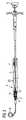
図1は、この特定の例ではヒトの心臓の左室2を支援するための血管内血液ポンプ1の使用を示す。血管内血液ポンプ1は、カテーテル5およびポンピングデバイスを備え、ポンピングデバイスは、カテーテル5の遠位端領域に取り付けられるポンプ区域4を備える。血管内血液ポンプ1は、経皮経管的技術を使用して心臓の内側に置かれ得る。例えば、血管内血液ポンプ1は、大腿動脈を通じて導入され得る。しかしながら、鎖骨下動脈を通じたアクセスなど、代替の血管アクセスが同様に可能である。大腿動脈を通過した後、カテーテル5は、ポンプ区域4が大動脈弁を通って心臓内へ到達するように、大動脈内へ押し込まれ得る。図1におけるポンプ区域4の位置付けは、単に例としての役割を果たすにすぎず、心臓の右室の内側にポンプ区域4を位置付けることなど、異なる配置が可能である。 FIG. 1 shows the use of an intravascular blood pump 1 to support the left ventricle 2 of the human heart in this particular example. The intravascular blood pump 1 comprises a
ポンプ区域4は、ポンプ区域4の遠位端における血流入口6から血流入口6の近位に位置する血流出口7まで血液を流すためにロータ10を備える。カテーテル5は、好ましくは患者の身体の外側に置かれる電気モータ8によって駆動される駆動軸12を収容する。駆動軸12は、ポンプ区域4の内側に含まれるロータを駆動する。ポンプ区域4は、その遠位端において、ピッグテールまたはJ字形の形態を有する可撓性の高い無傷先端9を保有し、これが、患者の血管系の内側でのナビゲーションを助けることにより血管内血液ポンプ1の配置を容易にする。さらには、可撓性の高い無傷先端9の柔らかさは、ポンプ区域4が左室2の壁に対して無傷に自立することを可能にする。 The pump section 4 comprises a
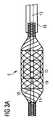
図2は、血管内血液ポンプ1をさらに詳細に示す。ロータ10は、ハウジング11の内側に位置する。この実施形態では、ロータ10およびハウジング11の両方が圧縮可能である。この場合、血管内血液ポンプ1は、ロータ10およびハウジング11の両方が圧縮した状態にある間、患者の血管系を通じて輸送される。ポンプ区域4がその標的位置に来ると、ハウジング11およびロータ10は拡張される。可撓性の高い無傷先端9は、ハウジング11の遠位端に位置付けられる。駆動軸12は、可撓性の高い駆動軸ケーブルとして実現される。駆動軸12の遠位端に配置されるロータ10を伴う駆動軸12は、カテーテル5の遠位端から突き出て見える。ハウジング11の内側のロータ10が駆動軸12により回転されるとき、血液は、ハウジング11の遠位端における血流入口6内へ、およびハウジング11を通って、ハウジング11に装着され近位に延びる下流チュービング20内へ運ばれる。血液は、次いで、下流チュービング20から、下流チュービング20内に提供される、より近くに位置する血流出口7を通って、大動脈内へ放出される。下流チュービング20は、患者の心臓が拍動しているとき大動脈弁によって圧縮され得るように、可撓性の高い材料で作製される。下流チュービング20は、典型的には、回転中のロータ10によって生成される活性血流に主に起因して拡張される。左室2の内側に血流入口6および大動脈の内側に血流出口7を置くことにより、血管内血液ポンプ1は、患者の全身血液循環を支援し得る。血管内血液ポンプ1が異なって構成され、置かれる場合、それは、例えば、代わりに患者の肺血液循環を支援するために使用され得る。 Figure 2 shows the intravascular blood pump 1 in more detail. The
この例では、液体、特にパージ流体は、患者の身体の外側からカテーテル5を通ってポンプ区域4へ供給される。ポンプ区域4の内側では、液体は、図4および図5に関連してさらに説明されるように、摩擦を低減し、ポンプ区域4を冷却するために、1つ以上の軸受をパージするために使用され得る。好ましくは、液体は、少なくとも遠位軸受をパージするために使用される。そのような場合、パージ流体の圧力は、血液が軸受に入ることを防ぐために、患者の血圧よりも高くなるように選択される。好ましくは、パージ流体の圧力は、300mmHg(0.4バール)~1500mmHg(2バール)の範囲、より好ましくは、600mmHg(0.8バール)~1100mmHg(およそ1.5バール)の範囲にある。 In this example, liquid, particularly purge fluid, is supplied from outside the patient's body through
ハウジング11は、好ましくは、ニチノールなどの形状記憶材料から製作され、ロータ10の周りにケージを提供する。図5に見られるように、ハウジング11の中央部は、チャネルを画定するスリーブを保持し、このチャネルを通じて血液がロータ10により圧送される。このチャネルの近位および遠位では、ハウジング11は、血液がハウジング11内へ吸い込まれ、ハウジング11から下流チュービング20内へ押し出されることを可能にする(図2に示されるように)。
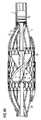
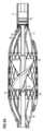
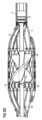
図3Aおよび図3Bは、それぞれ拡張した状態および圧縮した状態にある、ポンプ区域4、そのロータ10、ならびにそのハウジング11を示す。カニューレ16は、カテーテル5の遠位端に配置される。最初、血管内血液ポンプ1の配備前、ポンプ区域4は、カニューレ16の内側にその圧縮した状態で提供される。カニューレ16は、患者の身体内へのカテーテル5の挿入を助けるためにカテーテル5またはピールアウェイシースに付属するカニューレ16であってもよい。カテーテル5が患者の血管系の内側に正しく置かれることを医師が決定したとき、医師は、ハウジング11をカニューレ16の外へ押し出す。カニューレ16が除去されると、ハウジング11は、その形状記憶特性に起因して拡張する。同時に、ロータ10は、その弾性に起因して拡張する。ハウジング11が駆動軸12から離れる方へ径方向に拡張すると、それは、長手方向に収縮する。 Figures 3A and 3B show the pump section 4, its
ロータ10は、ピン19を有する静的支持部材18を備える遠位軸受14によって、ロータ10の遠位区域内に支持され、静的支持部材18は、その一端でハウジング11に装着され、その反対端でそのピン19によりロータ10の遠位端内へ延びるため、ハウジング11の拡張の際、ピン19は、ロータの遠位端10の内側で軸方向に移動することができる。好ましくは、ピン19は、ハウジング11がその圧縮した状態にあるとき、ピン19がロータ10の内側に留まるために十分に長い。血管内血液ポンプ1がその拡張した状態にあり、心臓から除去される必要があるとき、医師は、ハウジング11をカニューレ16内へ引き戻し、これによりハウジング11を径方向に圧縮して、長手方向に延長させ、その結果として、ハウジング11の遠位端が、静的支持部材18およびロータ10の遠位端内へ延びるそのピン19と一緒にロータ10から離れる方へ移動する。こうして達成されるハウジング11のより小さい直径は、患者からの血管内血液ポンプ1の除去を容易にする。 The
先行技術の遠位軸受14において、駆動軸12は、時として、ロータ10の遠位に、軸受内へ延びる。しかしながら、これは、心臓の腱索が駆動軸12と絡み合うことを引き起こし得、可能性として凝固およびデバイス故障につながる。したがって、ロータ10に対して遠位およびロータ羽根に対して遠位の回転部分に関与しない、遠位軸受14の一部としての静的支持部材18の使用が有利である。 In prior art
図4Aおよび図4Bは、ハウジング11、および駆動軸12によって駆動されるロータ10を含め、第1の実施形態によるポンプ区域4をさらに詳細に説明する。駆動軸12は、ロータ10の近位の(またはハウジングの近位部内の)カテーテル5の遠位端における近位軸受13、およびロータ10の遠位端に位置する遠位軸受14の両方において回転可能に支持される。図4Aでは、駆動軸12は、その遠位端において中空であり、またはより詳細には、ロータ軸は、流体ライン15を形成するように中空であり、この流体ライン15を通ってパージ流体が遠位軸受14の方へ圧送され得る。駆動軸が中空であり、ロータ10の遠位端まで延びる場合、ロータ10は、ロータ軸が駆動軸によって形成されるように駆動軸12の遠位端に直接形成され得、これにより、近位および遠位軸受の領域において、駆動軸12は、例えば射出成形塑性材料によって補剛され、それぞれ適切な外側および内側軸受表面仕上げを提供され得る。代替的に、駆動軸12の軸受区域を含む端領域全体は、ポンプ区域のより堅い構造を得るために補剛され得る。例えば、堅い中空管が、駆動軸12の端の上にかぶせられ、遠位に延びてロータ軸および軸受区域を形成する。パージ流体は、ロータ軸内の流体ライン15を通って遠位軸受14へ輸送され得る。図4Aに示される実施形態において、パージ流体は、中央流体ライン15を通ることを強いられて、駆動軸12をその遠位端において出て、遠位軸受14の軸受隙間をさらに通って、血流内へ出る。パージ流体による遠位軸受14のパージは、より少ない摩擦、故に、遠位軸受に対するより少ない摩耗をもたらし、さらには、血液が軸受隙間内に入って詰まることを防ぐ。 4A and 4B describe in more detail the pump section 4 according to the first embodiment, including the
血管内血液ポンプ1が効率的であるためには、大きいロータ10直径が望ましい。しかしながら、ロータ10とハウジング11との間の隙間が小さくなるにつれて、血液細胞またはロータ10が損傷されるリスクが増大する。近位軸受13のみが使用される場合、本システムは振動し得、ロータ10の羽根の先端とハウジング11の内面との間の隙間は、大きな変化を経る場合がある。可撓性の高い無傷先端9が心臓壁に接触するとき、心臓の運動がハウジングの屈曲を引き起こし得、これはハウジングがロータに接触することをもたらし得る。使用中のハウジングおよびロータの接触は、血液細胞への損傷の著しい増大を引き起こし得る。図4Aおよび図4Bに例証されるように、近位軸受13および遠位軸受14の両方を使用することにより、ロータ10の位置はより安定し、上記隙間のサイズの変動は、1つだけの軸受の場合よりも低い。所定のハウジング11では、これは、ロータ10直径がより大きくなることを可能にし得、これによりハウジングがロータに接触することなく血管内血液ポンプ1のより高い流量を可能にする。 A
ロータ10は、その遠位端に、凹部17を備える。ハウジング11の遠位端に対して固定される静的支持部材18は、そのピン19により凹部17内へ突き出る。図4A内の凹部17の底19は、段として形成され、ロータ10の内側の停止部を画定し、この停止部に当接して静的支持部材18のピン19は静止することができる。図4Aでは、流体ライン15は、パージ流体がピン19と凹部17との間の遠位軸受14から出ることを可能にするために、凹部17の底を貫通する。
図4B内の血管内血液ポンプ1の実施形態は、図4A内の実施形態と類似している。しかしながら、重要なことには、図4B内の遠位軸受は、パージされず、代わりに血液内で動作するように設計される。故に、駆動軸12は、中空である必要がない。したがって、図4Bには流体ライン15が存在しない。凹部17の底は、パージ流体がピン19と凹部17との間の軸受隙間を通って流れるための開口部を含まない。そのような実施形態においては、より少ないパージ流体が必要とされ得る。近位軸受がパージされない場合、血管内血液ポンプは、パージ流体を全く必要としない場合がある。 The embodiment of intravascular blood pump 1 in Figure 4B is similar to the embodiment in Figure 4A. Importantly, however, the distal bearing in FIG. 4B is not purged and is instead designed to operate in blood. Therefore, the
図4Cは、図4Aおよび図4Bと類似の実施形態を示す。ここでは、ピン19は、特に長く、近位にロータ軸を通って、および駆動軸12内へ、延びる。図4Cの実施形態では、ピン19の近位端は、近位軸受13の内側に位置する駆動軸12の部分の内側に位置する。代替の実施形態において、ピン19の近位端は、例えば、近位軸受13の近位に、またはロータと近位軸受との間に位置し得る。 FIG. 4C shows an embodiment similar to FIGS. 4A and 4B. Here the
近位軸受13内へ延びるピン19を有することにより、血管内血液ポンプ1のより大きい剛性が達成され得る。さらには、図4Cに示されるピン19は、血管内血液ポンプ1の振動を、その動作中に低減するのに役立ち得、また望ましくない屈曲を減少させ得る。 By having the
図4C内の近位軸受13は、図4Aおよび図4B内の近位軸受13の場所から遠位に、ハウジング11の内側に位置する。近位軸受13とロータ10との間の距離は、示される実施形態において特に小さく、例えば、近位軸受13の外径よりも小さい。短距離は、血管内血液ポンプ1の剛性をさらに増大させ得る。 The
図4C内のピン19は、いくつかの実施形態において、パージ流体が、駆動軸12を通って流れ、ピン19を過ぎてロータ10の遠位端で出ることができるように、中空駆動軸12と組み合わされ得る。代替的に、いくつかの実施形態において、パージ流体は使用されない場合がある。この場合、図4Cの長いピン19は、中空でない、または長さのいくらかの部分に沿ってのみ中空である駆動軸と組み合わされ得る。
図5は、圧縮可能なハウジング11および中空駆動軸12によって駆動されるロータ10をここでも伴って第2の実施形態によるポンプ区域4を示し、中空駆動軸12は、カテーテル5の遠位端においてロータ10の近位に配置される近位軸受13内に回転可能に支持される。 FIG. 5 shows a pump section 4 according to a second embodiment, again with a
この実施形態において、遠位軸受14の一部を形成する静的支持部材18のピン19は、尖った端を有する。ハウジング11およびピン19の寸法が、ハウジング11が圧縮されるときにピン19がロータ10から出るようなものである場合、ピン19の尖った端は、ハウジング11が再び拡張されるとき、ロータの遠位端10における開口部内へのピン19の再導入を容易にする。好ましくは、ピン19は、ハウジング11が圧縮した状態にあるとき、ピン19がロータ10の内側に留まるために十分に長い。これは、ハウジング11が拡張されているときにピン19がロータ10に再び入ることができない状況を回避し得る。場合によっては、必要な軸受隙間がピン19の全長にわたって存在する適切な機能は必要ではない。むしろ、ピン19の外側とその反対側の軸受表面との間の軸受隙間は、少なくとも1つの場所において、1μm~10μm、より好ましくは、2μm~8μmの幅であれば十分である。 In this embodiment, the
この実施形態では、ロータの遠位端10における開口部内に底または段を提供するよりも、静的支持部材18には、ショルダが設けられてもよく、このショルダに対して、ロータ10は、ハウジング11の拡張した状態において当接し、以て、所望の場合、ハウジング11のさらなる拡張を制限する。いくつかの実施形態において、遠位軸受14は、排他的に径方向軸受であってもよい。 In this embodiment, rather than providing a bottom or step in the opening at the
ここでも、パージ流体は、駆動軸12の流体ライン15を通って遠位軸受14の方へ供給され、ロータ10のための遠位径方向軸受を形成するピン19を通過し、ロータ10からその遠位端において出ることができる。これは、血液がロータ10に入ることを防ぎ、摩擦を低減し、遠位軸受14を冷却する。代替的に、遠位軸受14は、パージされなくてもよい。したがって、流体ライン15は存在しなくてもよい。 Again, purge fluid is supplied through
さらには、図5に示される実施形態において、ピン19は、ハウジング11が拡張されるとき、ロータ10の中央ダクトの内側にある。この場合、例えば、駆動軸12は、ロータ10の遠位端面において終端し得る。代替的に、駆動軸12の遠位端は、ピン19のための停止部を形成するように、ロータ10の内側に、例えば、図4Aの実施形態に見られるように、凹部の底のレベルに位置し得る。 Furthermore, in the embodiment shown in Figure 5, the
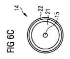
図6A、図6B、図6C、および図6Dは、圧縮可能なハウジング11、およびハウジング11に装着される静的支持部材18を伴うポンプ区域4の第3の実施形態を示す。ロータ10は、その遠位端にノーズ部21を備える。図6A、図6B、および図6Cでは、駆動軸12の遠位端の内側の流体ライン15は、ノーズ部21内の開口部へつながり、この開口部を通って、パージ流体は、静的支持部材18の近位端においてノーズ部21と対応する凹部22との間の遠位軸受14の軸受隙間に入ることができる。しかしながら、図6Dでは、遠位軸受14はパージされない。故に、図6Dの実施形態は、流体ライン15およびノーズ部21内の開口部を保有しない。パージされない遠位軸受14は、血管内血液ポンプ1を動作させるのに必要とされるパージ流体の量を減少させ得る。パージされない近位軸受13と組み合わせると、血管内血液ポンプ1は、パージ流体を全く必要としなくてもよい。 6A, 6B, 6C, and 6D show a third embodiment of pump section 4 with
ハウジング11が圧縮されるとき、ノーズ部21は、凹部22から外れ、故に、血管内血液ポンプ1はより可撓性が高くなる。ハウジング11が標的部位において拡張されるとき、ノーズ部21は、凹部22内へ自動的に移動し、ノーズ部21の円すい形もしくは球形は、ノーズ部21を凹部22内へ誘導するのを助け、ロータ10を静的支持部材18に対して中心に置く。図6Bは、ロータ10におけるノーズ部21および対応する凹部22を伴う遠位軸受14の拡大断面を示す。図6B内の垂直鎖線は、図6Cの断面平面を示す。図6Cに提示される断面は、遠位軸受14を同心円で表示する。周辺から中心へ、同心円は、凹部22、凹部22とノーズ部21との間の遠位軸受隙間、ノーズ部21、および遠位軸受隙間内への流体ライン15の開口部を示す。 When the
図7は、血管内血液ポンプ1をそのカテーテル5およびそのポンプ区域4と共に示す。この実施形態では、血管内血液ポンプ1は、カテーテル5の遠位端の内側に近位軸受13を備える。パージ流体は、このときカテーテル5を通って流れ、その軸受隙間を通って近位軸受13を出る。パージ流体のうちの一部は、駆動軸12を通ってロータ10内へも流れる。
近位軸受の軸受隙間は、好ましくは、1μm~10μm、より好ましくは、2μm~8μmである。FIG. 7 shows an intravascular blood pump 1 with its
The bearing clearance of the proximal bearing is preferably between 1 μm and 10 μm, more preferably between 2 μm and 8 μm.
ロータの内側の駆動軸12から、パージ流体は、流体ライン15を通ってロータ10の凹部17内へ流れる。凹部17の内側に配置されるのは、ロータ10の遠位軸受スリーブ25である。遠位軸受スリーブ25の内面およびピン19の外面は、遠位軸受14の軸受表面を形成する。パージ流体は、遠位軸受スリーブ25とピン19との間の軸受隙間を介してロータ10から出る。 From
遠位軸受スリーブ25は、好ましくは、0.3mm~1.5mm、より好ましくは、0.5mm~1.2mm、および最も好ましくは、0.7mm~0.9mmの内径を有する。遠位軸受25のスリーブの外径は、好ましくは、0.5mm~1.7mm、より好ましくは、0.7mm~1.4mm、および最も好ましくは、0.9mm~1.1mmである。ピン19と遠位軸受スリーブ25との間の軸受隙間は、好ましくは、1μm~10μm、より好ましくは、2μm~8μmである。
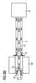
図8Aは、血管内血液ポンプの内側のパージ流体経路を概略的に示す。モータ8のハウジングの内側で、パージ流体は、カテーテル5内へ、および駆動軸12内へ供給される。近位軸受13において、パージ流体は、摩擦を低減し、近位軸受13を冷却するために軸受隙間を通じてカテーテル5から出る。パージ流体の一部分は、軸受隙間を通じてカテーテル5から出ずに、駆動軸12を通ってロータ10内へ流れる。いくつかの実施形態において、駆動軸12は、パージ流体が、カテーテル5の遠位端とロータ10の近位端との間で駆動軸12から漏出することなしにカテーテル5からロータ10へ流れることができるようにカバーを備え得る。ロータ10の内側で、パージ流体は、流体ライン15を通って、次いでロータの遠位端10において凹部17内へ流れ続ける。代替の実施形態において、駆動軸12は、パージ流体が駆動軸12から直接的に凹部17内へ流れるように、凹部17に至るまで、または凹部17内へ続き得る。そこから、パージ流体は、ピン19とロータ10の隣接面との間の遠位軸受14の軸受隙間を通って流れる。 FIG. 8A schematically shows a purge fluid path inside an intravascular blood pump. Inside the
図8Bは、図8Aに類似する血液ポンプの実施形態を示す。図8Bでは、近位軸受13は、図8Aの場合よりもロータ10に近く、小さい隙間によってのみロータ10から分離される。上記隙間を通じて、パージ流体は、矢印に示されるように漏れ得る。
FIG. 8B shows an embodiment of a blood pump similar to FIG. 8A. In Figure 8B, the
Claims (17)
Translated fromJapanese駆動軸(12)と、
前記駆動軸(12)の遠位端に位置するロータ(10)と、
前記ロータ(10)が収容されるハウジング(11)と、
前記ロータ(10)の遠位端を回転可能に支持するための遠位軸受(14)と
を備え、
前記遠位軸受(14)は、前記ロータ(10)の前記遠位端内へ、またはこれに直面して突き出る静的支持部材(18)を備えることを特徴とする、血管内血液ポンプ(1)。An intravascular blood pump (1) comprising a pumping device and a catheter (5), said pumping device comprising:
a drive shaft (12);
a rotor (10) located at the distal end of the drive shaft (12);
a housing (11) in which the rotor (10) is housed;
a distal bearing (14) for rotatably supporting the distal end of the rotor (10);
An intravascular blood pump (1) characterized in that said distal bearing (14) comprises a static support member (18) projecting into or facing said distal end of said rotor (10). ).
Use of an intravascular blood pump (1) according to any one of claims 1 to 16 in a patient, so that blood flow in said patient is supported by said intravascular blood pump (1). A method characterized by
Priority Applications (1)
| Application Number | Priority Date | Filing Date | Title |
|---|---|---|---|
| JP2025068492AJP2025108634A (en) | 2020-01-31 | 2025-04-18 | Intravascular Blood Pump |
Applications Claiming Priority (3)
| Application Number | Priority Date | Filing Date | Title |
|---|---|---|---|
| EP20154827.8AEP3858397A1 (en) | 2020-01-31 | 2020-01-31 | Intravascular blood pump |
| EP20154827.8 | 2020-01-31 | ||
| PCT/EP2021/052002WO2021152019A1 (en) | 2020-01-31 | 2021-01-28 | Intravascular blood pump |
Related Child Applications (1)
| Application Number | Title | Priority Date | Filing Date |
|---|---|---|---|
| JP2025068492ADivisionJP2025108634A (en) | 2020-01-31 | 2025-04-18 | Intravascular Blood Pump |
Publications (2)
| Publication Number | Publication Date |
|---|---|
| JP2023513034Atrue JP2023513034A (en) | 2023-03-30 |
| JP7671301B2 JP7671301B2 (en) | 2025-05-01 |
Family
ID=69423133
Family Applications (2)
| Application Number | Title | Priority Date | Filing Date |
|---|---|---|---|
| JP2022546353AActiveJP7671301B2 (en) | 2020-01-31 | 2021-01-28 | Intravascular Blood Pump |
| JP2025068492APendingJP2025108634A (en) | 2020-01-31 | 2025-04-18 | Intravascular Blood Pump |
Family Applications After (1)
| Application Number | Title | Priority Date | Filing Date |
|---|---|---|---|
| JP2025068492APendingJP2025108634A (en) | 2020-01-31 | 2025-04-18 | Intravascular Blood Pump |
Country Status (12)
| Country | Link |
|---|---|
| US (1) | US20220347458A1 (en) |
| EP (2) | EP3858397A1 (en) |
| JP (2) | JP7671301B2 (en) |
| KR (1) | KR20220132003A (en) |
| CN (1) | CN115038490A (en) |
| AU (1) | AU2021213428A1 (en) |
| CA (1) | CA3162859A1 (en) |
| DE (1) | DE112021000797T5 (en) |
| IL (1) | IL294623A (en) |
| NZ (1) | NZ791555A (en) |
| TW (1) | TW202130376A (en) |
| WO (1) | WO2021152019A1 (en) |
Families Citing this family (19)
| Publication number | Priority date | Publication date | Assignee | Title |
|---|---|---|---|---|
| DE102018201030B4 (en) | 2018-01-24 | 2025-10-16 | Kardion Gmbh | Magnetic dome element with magnetic bearing function |
| DE102018207575A1 (en) | 2018-05-16 | 2019-11-21 | Kardion Gmbh | Magnetic face turning coupling for the transmission of torques |
| DE102018207611A1 (en) | 2018-05-16 | 2019-11-21 | Kardion Gmbh | Rotor bearing system |
| DE102018208541A1 (en) | 2018-05-30 | 2019-12-05 | Kardion Gmbh | Axial pump for a cardiac assist system and method of making an axial pump for a cardiac assist system |
| DE102018208538A1 (en) | 2018-05-30 | 2019-12-05 | Kardion Gmbh | Intravascular blood pump and process for the production of electrical conductors |
| DE102018208539A1 (en) | 2018-05-30 | 2019-12-05 | Kardion Gmbh | A motor housing module for sealing an engine compartment of a motor of a cardiac assist system and cardiac assistance system and method for mounting a cardiac assist system |
| DE102018208550A1 (en) | 2018-05-30 | 2019-12-05 | Kardion Gmbh | A lead device for directing blood flow to a cardiac assist system, cardiac assist system, and method of making a lead device |
| DE102018210058A1 (en) | 2018-06-21 | 2019-12-24 | Kardion Gmbh | Stator blade device for guiding the flow of a fluid flowing out of an outlet opening of a heart support system, heart support system with stator blade device, method for operating a stator blade device and manufacturing method |
| DE102018210076A1 (en) | 2018-06-21 | 2019-12-24 | Kardion Gmbh | Method and device for detecting a state of wear of a cardiac support system, method and device for operating a cardiac support system and cardiac support system |
| DE102018211327A1 (en) | 2018-07-10 | 2020-01-16 | Kardion Gmbh | Impeller for an implantable vascular support system |
| DE102018212153A1 (en) | 2018-07-20 | 2020-01-23 | Kardion Gmbh | Inlet line for a pump unit of a cardiac support system, cardiac support system and method for producing an inlet line for a pump unit of a cardiac support system |
| CN112654389A (en) | 2018-08-07 | 2021-04-13 | 开迪恩有限公司 | Bearing device for a cardiac support system and method for flushing an intermediate space in a bearing device for a cardiac support system |
| EP3858399A1 (en)* | 2020-01-31 | 2021-08-04 | ECP Entwicklungsgesellschaft mbH | Intravascular blood pump |
| DE102020102474A1 (en) | 2020-01-31 | 2021-08-05 | Kardion Gmbh | Pump for conveying a fluid and method for manufacturing a pump |
| CN113713233B (en)* | 2021-08-23 | 2022-07-22 | 苏州心擎医疗技术有限公司 | Interventional catheter device |
| WO2023070515A1 (en)* | 2021-10-29 | 2023-05-04 | 苏州心擎医疗技术有限公司 | Catheter pump |
| US20250135185A1 (en)* | 2022-02-02 | 2025-05-01 | Shifamed Holdings, Llc | Pump systems and methods |
| CN219231205U (en)* | 2022-12-20 | 2023-06-23 | 丰凯利医疗器械(上海)有限公司 | Ventricular assist device |
| CN116328174B (en)* | 2023-03-01 | 2024-03-12 | 心擎医疗(苏州)股份有限公司 | Catheter pump and filter assembly method thereof |
Citations (3)
| Publication number | Priority date | Publication date | Assignee | Title |
|---|---|---|---|---|
| US5851174A (en)* | 1996-09-17 | 1998-12-22 | Robert Jarvik | Cardiac support device |
| US20130303970A1 (en)* | 2012-05-14 | 2013-11-14 | Thoratec Corporation | Distal bearing support |
| JP2016000353A (en)* | 2009-07-01 | 2016-01-07 | ザ・ペン・ステイト・リサーチ・ファウンデイションThe Penn State Research Foundation | Blood pump with expandable cannula |
Family Cites Families (29)
| Publication number | Priority date | Publication date | Assignee | Title |
|---|---|---|---|---|
| US4014317A (en)* | 1972-02-18 | 1977-03-29 | The United States Of America As Represented By The Department Of Health, Education And Welfare | Multipurpose cardiocirculatory assist cannula and methods of use thereof |
| US3995617A (en)* | 1972-05-31 | 1976-12-07 | Watkins David H | Heart assist method and catheter |
| JPH0636821B2 (en)* | 1990-03-08 | 1994-05-18 | 健二 山崎 | Implantable auxiliary artificial heart |
| US5376114A (en)* | 1992-10-30 | 1994-12-27 | Jarvik; Robert | Cannula pumps for temporary cardiac support and methods of their application and use |
| US6245007B1 (en)* | 1999-01-28 | 2001-06-12 | Terumo Cardiovascular Systems Corporation | Blood pump |
| AU2003236497A1 (en)* | 2002-06-11 | 2003-12-22 | Walid Aboul-Hosn | Expandable blood pump and related methods |
| US20060089521A1 (en)* | 2004-10-21 | 2006-04-27 | Chang Sheldon S L | Rotor driven linear flow blood pump |
| US9028392B2 (en)* | 2006-12-01 | 2015-05-12 | NuCardia, Inc. | Medical device |
| EP2047873B1 (en) | 2007-10-08 | 2010-12-15 | Ais Gmbh Aachen Innovative Solutions | Catheter device |
| US8439859B2 (en)* | 2007-10-08 | 2013-05-14 | Ais Gmbh Aachen Innovative Solutions | Catheter device |
| EP2248544A1 (en)* | 2009-05-05 | 2010-11-10 | ECP Entwicklungsgesellschaft mbH | Fluid pump with variable circumference, particularly for medical use |
| US8597170B2 (en)* | 2011-01-05 | 2013-12-03 | Thoratec Corporation | Catheter pump |
| DE102012202411B4 (en)* | 2012-02-16 | 2018-07-05 | Abiomed Europe Gmbh | INTRAVASAL BLOOD PUMP |
| US8721517B2 (en)* | 2012-05-14 | 2014-05-13 | Thoratec Corporation | Impeller for catheter pump |
| US9872947B2 (en) | 2012-05-14 | 2018-01-23 | Tc1 Llc | Sheath system for catheter pump |
| US9308302B2 (en)* | 2013-03-15 | 2016-04-12 | Thoratec Corporation | Catheter pump assembly including a stator |
| DE112014001418T5 (en)* | 2013-03-15 | 2015-12-17 | Minnetronix, Inc. | Expandable blood pump for cardiac support |
| US10293090B2 (en)* | 2014-04-25 | 2019-05-21 | Yale University | Percutaneous device and method for promoting movement of a bodily fluid |
| WO2015175711A1 (en)* | 2014-05-13 | 2015-11-19 | Abiomed, Inc. | Blood pump housing component |
| WO2016086137A1 (en)* | 2014-11-26 | 2016-06-02 | Thoratec Corporation | Pump and method for mixed flow blood pumping |
| DK3795208T3 (en)* | 2015-03-18 | 2023-12-11 | Abiomed Europe Gmbh | BLOOD PUMP |
| US9907890B2 (en)* | 2015-04-16 | 2018-03-06 | Tc1 Llc | Catheter pump with positioning brace |
| EP4548956A3 (en)* | 2015-08-04 | 2025-08-06 | Abiomed Europe GmbH | Blood pump with self-flushing bearing |
| DE102017102828A1 (en)* | 2017-02-13 | 2018-08-16 | Cardiobridge Gmbh | Catheter pump with a pump head for insertion into the arterial vasculature |
| EP3398624A1 (en)* | 2017-05-04 | 2018-11-07 | Abiomed Europe GmbH | Blood pump with reinforced catheter |
| US10668195B2 (en)* | 2018-06-01 | 2020-06-02 | Fbr Medical, Inc. | Catheter pump with fixed-diameter impeller |
| WO2020003110A2 (en)* | 2018-06-25 | 2020-01-02 | Modeus Inc. | Percutaneous blood pump and introducer system |
| EP3858398A1 (en)* | 2020-01-31 | 2021-08-04 | ECP Entwicklungsgesellschaft mbH | Intravascular blood pump |
| EP3858399A1 (en)* | 2020-01-31 | 2021-08-04 | ECP Entwicklungsgesellschaft mbH | Intravascular blood pump |
- 2020
- 2020-01-31EPEP20154827.8Apatent/EP3858397A1/ennot_activeWithdrawn
- 2021
- 2021-01-28TWTW110103232Apatent/TW202130376A/enunknown
- 2021-01-28CACA3162859Apatent/CA3162859A1/enactivePending
- 2021-01-28USUS17/793,578patent/US20220347458A1/enactivePending
- 2021-01-28NZNZ791555Apatent/NZ791555A/enunknown
- 2021-01-28AUAU2021213428Apatent/AU2021213428A1/enactivePending
- 2021-01-28JPJP2022546353Apatent/JP7671301B2/enactiveActive
- 2021-01-28KRKR1020227030223Apatent/KR20220132003A/enactivePending
- 2021-01-28CNCN202180012456.8Apatent/CN115038490A/enactivePending
- 2021-01-28ILIL294623Apatent/IL294623A/enunknown
- 2021-01-28DEDE112021000797.1Tpatent/DE112021000797T5/enactivePending
- 2021-01-28WOPCT/EP2021/052002patent/WO2021152019A1/ennot_activeCeased
- 2021-01-28EPEP21702475.1Apatent/EP4096768A1/enactivePending
- 2025
- 2025-04-18JPJP2025068492Apatent/JP2025108634A/enactivePending
Patent Citations (3)
| Publication number | Priority date | Publication date | Assignee | Title |
|---|---|---|---|---|
| US5851174A (en)* | 1996-09-17 | 1998-12-22 | Robert Jarvik | Cardiac support device |
| JP2016000353A (en)* | 2009-07-01 | 2016-01-07 | ザ・ペン・ステイト・リサーチ・ファウンデイションThe Penn State Research Foundation | Blood pump with expandable cannula |
| US20130303970A1 (en)* | 2012-05-14 | 2013-11-14 | Thoratec Corporation | Distal bearing support |
Also Published As
| Publication number | Publication date |
|---|---|
| CA3162859A1 (en) | 2021-08-05 |
| EP4096768A1 (en) | 2022-12-07 |
| JP2025108634A (en) | 2025-07-23 |
| IL294623A (en) | 2022-09-01 |
| KR20220132003A (en) | 2022-09-29 |
| EP3858397A1 (en) | 2021-08-04 |
| TW202130376A (en) | 2021-08-16 |
| AU2021213428A1 (en) | 2022-07-14 |
| US20220347458A1 (en) | 2022-11-03 |
| NZ791555A (en) | 2025-06-27 |
| CN115038490A (en) | 2022-09-09 |
| WO2021152019A1 (en) | 2021-08-05 |
| DE112021000797T5 (en) | 2022-12-15 |
| JP7671301B2 (en) | 2025-05-01 |
Similar Documents
| Publication | Publication Date | Title |
|---|---|---|
| JP7671301B2 (en) | Intravascular Blood Pump | |
| TWI877295B (en) | Intravascular blood pump | |
| TWI864228B (en) | Intravascular blood pump | |
| HK40080477A (en) | Intravascular blood pump | |
| HK40085777B (en) | Intravascular blood pump | |
| HK40085777A (en) | Intravascular blood pump | |
| HK40062448A (en) | Intravascular blood pump | |
| HK40062448B (en) | Intravascular blood pump |
Legal Events
| Date | Code | Title | Description |
|---|---|---|---|
| A621 | Written request for application examination | Free format text:JAPANESE INTERMEDIATE CODE: A621 Effective date:20240125 | |
| A131 | Notification of reasons for refusal | Free format text:JAPANESE INTERMEDIATE CODE: A131 Effective date:20240917 | |
| A521 | Request for written amendment filed | Free format text:JAPANESE INTERMEDIATE CODE: A523 Effective date:20241213 | |
| TRDD | Decision of grant or rejection written | ||
| A01 | Written decision to grant a patent or to grant a registration (utility model) | Free format text:JAPANESE INTERMEDIATE CODE: A01 Effective date:20250218 | |
| A601 | Written request for extension of time | Free format text:JAPANESE INTERMEDIATE CODE: A601 Effective date:20250314 | |
| A61 | First payment of annual fees (during grant procedure) | Free format text:JAPANESE INTERMEDIATE CODE: A61 Effective date:20250418 | |
| R150 | Certificate of patent or registration of utility model | Ref document number:7671301 Country of ref document:JP Free format text:JAPANESE INTERMEDIATE CODE: R150 |