JP2023509867A - Polarization imaging system and polarization imaging method - Google Patents
Polarization imaging system and polarization imaging methodDownload PDFInfo
- Publication number
- JP2023509867A JP2023509867AJP2022538903AJP2022538903AJP2023509867AJP 2023509867 AJP2023509867 AJP 2023509867AJP 2022538903 AJP2022538903 AJP 2022538903AJP 2022538903 AJP2022538903 AJP 2022538903AJP 2023509867 AJP2023509867 AJP 2023509867A
- Authority
- JP
- Japan
- Prior art keywords
- polarization
- type
- light
- color
- imaging system
- Prior art date
- Legal status (The legal status is an assumption and is not a legal conclusion. Google has not performed a legal analysis and makes no representation as to the accuracy of the status listed.)
- Pending
Links
Images


Classifications
- G—PHYSICS
- G02—OPTICS
- G02B—OPTICAL ELEMENTS, SYSTEMS OR APPARATUS
- G02B21/00—Microscopes
- G02B21/0004—Microscopes specially adapted for specific applications
- G02B21/0092—Polarisation microscopes
- G—PHYSICS
- G01—MEASURING; TESTING
- G01N—INVESTIGATING OR ANALYSING MATERIALS BY DETERMINING THEIR CHEMICAL OR PHYSICAL PROPERTIES
- G01N21/00—Investigating or analysing materials by the use of optical means, i.e. using sub-millimetre waves, infrared, visible or ultraviolet light
- G01N21/17—Systems in which incident light is modified in accordance with the properties of the material investigated
- G01N21/21—Polarisation-affecting properties
- G01N21/211—Ellipsometry
- G—PHYSICS
- G01—MEASURING; TESTING
- G01J—MEASUREMENT OF INTENSITY, VELOCITY, SPECTRAL CONTENT, POLARISATION, PHASE OR PULSE CHARACTERISTICS OF INFRARED, VISIBLE OR ULTRAVIOLET LIGHT; COLORIMETRY; RADIATION PYROMETRY
- G01J3/00—Spectrometry; Spectrophotometry; Monochromators; Measuring colours
- G01J3/02—Details
- G01J3/0205—Optical elements not provided otherwise, e.g. optical manifolds, diffusers, windows
- G01J3/0224—Optical elements not provided otherwise, e.g. optical manifolds, diffusers, windows using polarising or depolarising elements
- G—PHYSICS
- G01—MEASURING; TESTING
- G01J—MEASUREMENT OF INTENSITY, VELOCITY, SPECTRAL CONTENT, POLARISATION, PHASE OR PULSE CHARACTERISTICS OF INFRARED, VISIBLE OR ULTRAVIOLET LIGHT; COLORIMETRY; RADIATION PYROMETRY
- G01J3/00—Spectrometry; Spectrophotometry; Monochromators; Measuring colours
- G01J3/28—Investigating the spectrum
- G01J3/2823—Imaging spectrometer
- G—PHYSICS
- G01—MEASURING; TESTING
- G01J—MEASUREMENT OF INTENSITY, VELOCITY, SPECTRAL CONTENT, POLARISATION, PHASE OR PULSE CHARACTERISTICS OF INFRARED, VISIBLE OR ULTRAVIOLET LIGHT; COLORIMETRY; RADIATION PYROMETRY
- G01J3/00—Spectrometry; Spectrophotometry; Monochromators; Measuring colours
- G01J3/28—Investigating the spectrum
- G01J3/447—Polarisation spectrometry
- G—PHYSICS
- G01—MEASURING; TESTING
- G01J—MEASUREMENT OF INTENSITY, VELOCITY, SPECTRAL CONTENT, POLARISATION, PHASE OR PULSE CHARACTERISTICS OF INFRARED, VISIBLE OR ULTRAVIOLET LIGHT; COLORIMETRY; RADIATION PYROMETRY
- G01J3/00—Spectrometry; Spectrophotometry; Monochromators; Measuring colours
- G01J3/46—Measurement of colour; Colour measuring devices, e.g. colorimeters
- G01J3/50—Measurement of colour; Colour measuring devices, e.g. colorimeters using electric radiation detectors
- G01J3/51—Measurement of colour; Colour measuring devices, e.g. colorimeters using electric radiation detectors using colour filters
- G01J3/513—Measurement of colour; Colour measuring devices, e.g. colorimeters using electric radiation detectors using colour filters having fixed filter-detector pairs
- G—PHYSICS
- G01—MEASURING; TESTING
- G01J—MEASUREMENT OF INTENSITY, VELOCITY, SPECTRAL CONTENT, POLARISATION, PHASE OR PULSE CHARACTERISTICS OF INFRARED, VISIBLE OR ULTRAVIOLET LIGHT; COLORIMETRY; RADIATION PYROMETRY
- G01J4/00—Measuring polarisation of light
- G01J4/04—Polarimeters using electric detection means
- G—PHYSICS
- G01—MEASURING; TESTING
- G01N—INVESTIGATING OR ANALYSING MATERIALS BY DETERMINING THEIR CHEMICAL OR PHYSICAL PROPERTIES
- G01N21/00—Investigating or analysing materials by the use of optical means, i.e. using sub-millimetre waves, infrared, visible or ultraviolet light
- G01N21/17—Systems in which incident light is modified in accordance with the properties of the material investigated
- G01N21/21—Polarisation-affecting properties
- G—PHYSICS
- G01—MEASURING; TESTING
- G01B—MEASURING LENGTH, THICKNESS OR SIMILAR LINEAR DIMENSIONS; MEASURING ANGLES; MEASURING AREAS; MEASURING IRREGULARITIES OF SURFACES OR CONTOURS
- G01B11/00—Measuring arrangements characterised by the use of optical techniques
- G01B11/02—Measuring arrangements characterised by the use of optical techniques for measuring length, width or thickness
- G01B11/06—Measuring arrangements characterised by the use of optical techniques for measuring length, width or thickness for measuring thickness ; e.g. of sheet material
- G01B11/0616—Measuring arrangements characterised by the use of optical techniques for measuring length, width or thickness for measuring thickness ; e.g. of sheet material of coating
- G01B11/0625—Measuring arrangements characterised by the use of optical techniques for measuring length, width or thickness for measuring thickness ; e.g. of sheet material of coating with measurement of absorption or reflection
- G—PHYSICS
- G01—MEASURING; TESTING
- G01B—MEASURING LENGTH, THICKNESS OR SIMILAR LINEAR DIMENSIONS; MEASURING ANGLES; MEASURING AREAS; MEASURING IRREGULARITIES OF SURFACES OR CONTOURS
- G01B11/00—Measuring arrangements characterised by the use of optical techniques
- G01B11/02—Measuring arrangements characterised by the use of optical techniques for measuring length, width or thickness
- G01B11/06—Measuring arrangements characterised by the use of optical techniques for measuring length, width or thickness for measuring thickness ; e.g. of sheet material
- G01B11/0616—Measuring arrangements characterised by the use of optical techniques for measuring length, width or thickness for measuring thickness ; e.g. of sheet material of coating
- G01B11/0641—Measuring arrangements characterised by the use of optical techniques for measuring length, width or thickness for measuring thickness ; e.g. of sheet material of coating with measurement of polarization
- G01B11/065—Measuring arrangements characterised by the use of optical techniques for measuring length, width or thickness for measuring thickness ; e.g. of sheet material of coating with measurement of polarization using one or more discrete wavelengths
- G—PHYSICS
- G01—MEASURING; TESTING
- G01J—MEASUREMENT OF INTENSITY, VELOCITY, SPECTRAL CONTENT, POLARISATION, PHASE OR PULSE CHARACTERISTICS OF INFRARED, VISIBLE OR ULTRAVIOLET LIGHT; COLORIMETRY; RADIATION PYROMETRY
- G01J4/00—Measuring polarisation of light
- G—PHYSICS
- G01—MEASURING; TESTING
- G01N—INVESTIGATING OR ANALYSING MATERIALS BY DETERMINING THEIR CHEMICAL OR PHYSICAL PROPERTIES
- G01N21/00—Investigating or analysing materials by the use of optical means, i.e. using sub-millimetre waves, infrared, visible or ultraviolet light
- G01N21/17—Systems in which incident light is modified in accordance with the properties of the material investigated
- G01N21/21—Polarisation-affecting properties
- G01N21/211—Ellipsometry
- G01N2021/213—Spectrometric ellipsometry
- G—PHYSICS
- G06—COMPUTING OR CALCULATING; COUNTING
- G06T—IMAGE DATA PROCESSING OR GENERATION, IN GENERAL
- G06T3/00—Geometric image transformations in the plane of the image
- G06T3/40—Scaling of whole images or parts thereof, e.g. expanding or contracting
- G06T3/4015—Image demosaicing, e.g. colour filter arrays [CFA] or Bayer patterns
Landscapes
- Physics & Mathematics (AREA)
- Spectroscopy & Molecular Physics (AREA)
- General Physics & Mathematics (AREA)
- Chemical & Material Sciences (AREA)
- Analytical Chemistry (AREA)
- General Health & Medical Sciences (AREA)
- Life Sciences & Earth Sciences (AREA)
- Biochemistry (AREA)
- Health & Medical Sciences (AREA)
- Immunology (AREA)
- Pathology (AREA)
- Optics & Photonics (AREA)
- Color Television Image Signal Generators (AREA)
- Instruments For Viewing The Inside Of Hollow Bodies (AREA)
- Polarising Elements (AREA)
- Endoscopes (AREA)
- Investigating Or Analysing Materials By Optical Means (AREA)
Abstract
Translated fromJapaneseDescription
Translated fromJapanese本開示は、概して、偏光撮像システムおよび偏光撮像部に関する。 The present disclosure relates generally to polarization imaging systems and polarization imagers.
一般に偏光撮像が知られている。例えば、偏光フィルタは、例えば、材料(例えば、水)の反射率をフィルタリングするために、カメラに適用されてもよい。 Polarization imaging is generally known. For example, polarizing filters may be applied to the camera, eg, to filter the reflectance of materials (eg, water).
さらに、偏光撮像は、医療機器に、例えば、手術中に使用される外科用機器、例えば単眼内視鏡、または診断装置などにおいて使用される。 In addition, polarization imaging is used in medical instruments, such as surgical instruments used during surgery, such as monocular endoscopes, or diagnostic equipment.
例えば、人間の目には見えないかもしれない患者の組織特性(または解剖学的特徴)において、より広い洞察を有するためには、異なる組織が、典型的には異なる偏光に対する異なる反射特性を有する可能性があるため、偏光撮像を利用することができる。 For example, to have a broader insight into patient tissue properties (or anatomical features) that may not be visible to the human eye, different tissues typically have different reflection properties for different polarized light. Because of the potential, polarization imaging can be utilized.
このようなシステムでは、組織の等方性および異方性(光学的)特性の変化を解析することができる。 Such systems can analyze changes in isotropic and anisotropic (optical) properties of tissue.
したがって、試料(または患者の解剖学的部分)を互いに異なる組織を区別する方法で光学的に分解するためには、偏光撮像、例えばミュラー偏光分析法が広く使用されているツールである。 Therefore, polarized imaging, eg, Mueller ellipsometric analysis, is a widely used tool for optically resolving a sample (or patient anatomy) in a manner that distinguishes different tissues from each other.
他の光学システムは、組織の視認性を高めるための蛍光および/またはマーカー物質に基づいてもよい。それにより、リアルタイム画像化が実現され得る。 Other optical systems may be based on fluorescent and/or marker substances to enhance tissue visibility. Real-time imaging can thereby be achieved.
ミュラー偏光分析法撮像のための技術が存在するが、偏光撮像システムおよび偏光撮像方法を提供することが一般に望ましい。 Although techniques exist for Mueller ellipsometric imaging, it is generally desirable to provide polarization imaging systems and methods.
本開示は、第1の態様によると、第1のカラータイプのカラーチャネル素子、および、第2のカラータイプのカラーチャネル素子を有する撮像部と、第1のカラータイプに対して第1の偏光タイプの第1の光偏光を提供し、第2のカラータイプに対して第1の偏光タイプの第2の光偏光を提供し、第2の偏光タイプを第1の偏光タイプに変換し、それによって、第2の偏光タイプが撮像部において検出可能であるように構成された光偏光部とを具備する、偏光撮像システムを提供する。 The present disclosure provides, according to a first aspect, an imaging section having a color channel element of a first color type and a color channel element of a second color type; providing a first light polarization of a type, providing a second light polarization of the first polarization type for a second color type, converting the second polarization type to the first polarization type, and provides a polarized imaging system comprising a light polarizer configured such that a second polarization type is detectable at the imaging portion.
本開示は、第2の態様によると、第1のカラータイプのカラーチャネル素子に対して第1の偏光タイプの第1の光偏光を提供するステップと、第2のカラータイプのカラーチャネル素子に対して第1の偏光タイプの第2の光偏光を提供するステップと、第2の偏光タイプを第1の偏光タイプに変換するステップとを含み、それによって、第2の偏光タイプは、第1および第2のカラーチャネル素子を含む撮像部において検出可能である、偏光撮像方法を提供する。 The present disclosure provides, according to a second aspect, the steps of providing a first light polarization of a first polarization type to a color channel element of a first color type; and converting the second polarization type to the first polarization type, whereby the second polarization type converts to the first polarization type. and a second color channel element detectable in an imaging unit.
さらなる複数の態様が、従属請求項、以下の説明および図面に示されている。 Further aspects are presented in the dependent claims, the following description and the drawings.
本開示における実施形態は、添付の図面を参照して例として説明される。
図2を参照して実施形態を詳細に説明する前に、一般的な説明をする。 Before describing embodiments in detail with reference to FIG. 2, a general description is provided.
最初に述べたように、偏光撮像システムは、例えば、患者の異なる組織を術者が識別するのを支援するために使用される外科用デバイスなどにおいて、一般的に知られている。 As mentioned at the outset, polarized imaging systems are commonly known, for example, in surgical devices used to help an operator distinguish between different tissues in a patient.
一般に、そのような状況では、術者が関連する偏光情報をできるだけ迅速に得ることは、患者にとって(またはその健康にとって)極めて重要であり得る。 In general, in such situations it can be of great importance to the patient (or to their health) that the operator obtains relevant polarization information as quickly as possible.
しかしながら、例えばミュラー行列の要素が連続した取得ステップで測定されることがあるので、十分な偏光情報を得るために必要な取得回数が多すぎる可能性があるため、既存のミュラー極性測定システムが時間非効率性に働く可能性があることが認識されている。 However, the number of acquisitions required to obtain sufficient polarization information may be too large, for example, because the elements of the Mueller matrix may be measured in successive acquisition steps, so existing Mueller polar measurement systems are time-consuming. It is recognized that it can work inefficiently.
したがって、十分な偏光情報を得るための時間を短縮するためには、収集回数を減らすことが望ましい。 Therefore, it is desirable to reduce the number of acquisitions in order to shorten the time to obtain sufficient polarization information.
さらに、例えば診断学のような既知の偏光撮像システムの分解能を増加させることが望まれるが、手術装置についても同様である。 Furthermore, it is desirable to increase the resolution of known polarized imaging systems, eg for diagnostics, but also for surgical devices.
さらに、蛍光/マーカーレス・リアルタイム撮像法は知られていないが、これは、例えば、マーカー物質による健康リスクを低下させるため、手術(または診断)をステップ等により分解するため、一般的に望ましい。 Furthermore, fluorescence/markerless real-time imaging methods are not known, but this is generally desirable, for example, to reduce health risks due to marker substances, to break down surgery (or diagnosis) into steps, etc.
よって、実施形態によっては、第1のカラータイプのカラーチャネル素子、および、第2のカラータイプのカラーチャネル素子を有する撮像部と、第1のカラータイプに対して第1の偏光タイプの第1の光偏光を提供し、第2のカラータイプに対して第1の偏光タイプの第2の光偏光を提供し、第2の偏光タイプを第1の偏光タイプに変換することにより、第2の偏光タイプが撮像部において検出可能となるように構成された光偏光部と、を具備する、偏光撮像システムに関するものである。 Thus, in some embodiments, an imager having a color channel element of a first color type and a color channel element of a second color type and a first polarization type of a first polarization type for the first color type. by providing a second light polarization of the first polarization type for a second color type, and converting the second polarization type to the first polarization type. and a light polarizing unit configured such that the polarization type is detectable in the imaging unit.
撮像部は、CMOS(相補型金属酸化膜半導体)、CCD(電荷結合素子)等の公知の半導体技術、ダイオード技術等に基づくものであってもよい。 The imaging unit may be based on known semiconductor technology such as CMOS (Complementary Metal Oxide Semiconductor) and CCD (Charge Coupled Device), diode technology and the like.
さらに、撮像部は、少なくとも1つのSPAD (単一光子アバランシェダイオード)、CAPD (電流支援フォトニクス復調器)等を含んでもよい。 Furthermore, the imaging unit may include at least one SPAD (Single Photon Avalanche Diode), CAPD (Current Assisted Photonics Demodulator), or the like.
したがって、撮像部は、そのような技術に基づいて、複数の撮像要素(例えば、画素)(少なくとも2つ)を含んでもよく、それらは、アレイ、グリッド、パターンなどで配列されてもよい。 Accordingly, the imaging portion may include multiple imaging elements (eg, pixels) (at least two), which may be arranged in an array, grid, pattern, or the like, based on such techniques.
各撮像素子は、所定の波長(範囲)に感知できてもよく、言い換えれば、所定の色の種類(例えば、緑色(例えば、510~570ナノメートルの波長)、赤色(例えば、610~700ナノメートルの波長)、青色(例えば、400~480ナノメートルの波長)、赤外線に感知できてもよく、ここで、(ヒトについては)可視でない波長域は、色の種類(例えば、赤外線、紫外線)を指してもよい。
したがって、このような撮像素子に対して、カラーチャネル素子に言及されることがある。Each imager may be sensitive to a predetermined wavelength (range), in other words, a predetermined color class (e.g., green (e.g., 510-570 nanometer wavelength), red (e.g., 610-700 nanometer wavelength). meter wavelengths), blue (e.g. 400-480 nanometer wavelengths), infrared, where (for humans) the non-visible wavelength range is the color type (e.g. infrared, ultraviolet) You can point to
Accordingly, color channel devices are sometimes referred to for such imaging devices.
一般に、各撮像要素は、その点で本開示を制限することなく、異なるカラータイプに対して感知可能であり得る。例えば、(少なくとも)2つのカラーチャネル素子が同じ波長域に感知できる場合があり、他のカラーチャネル素子が少なくとも1つの異なる波長域に感知できる場合がある。 In general, each imaging element may be sensitive to different color types without limiting the present disclosure in that respect. For example, (at least) two color channel elements may be sensitive to the same wavelength range, and other color channel elements may be sensitive to at least one different wavelength range.
しかし、本開示に従う撮像部については、第1のカラータイプのカラーチャネル素子および第2のカラータイプのカラーチャネル素子を有していれば十分であろう。 However, for an imaging portion according to the present disclosure, it would be sufficient to have color channel elements of the first color type and color channel elements of the second color type.
偏光撮像システムは、光偏光部をさらに含んでもよい。 The polarized imaging system may further include a light polarizer.
光偏光部は、各カラーチャネル素子に対して少なくとも1つの偏光子を含む静的偏光子部を含んでもよい。 The light polarizer section may include a static polarizer section containing at least one polarizer for each color channel element.
静的偏光子部の各偏光子は、静的偏光子部の配置が画像形成部の少なくとも一部に対応し得るように、アレイ、グリッド、パターン等で配置され得る。 Each polarizer of the static polarizer section can be arranged in an array, grid, pattern, etc. such that the arrangement of the static polarizer section can correspond to at least a portion of the imaging section.
各偏光子は、偏光子上に入るかまたは通過する光になるように、所定の位相シフトを調整するように適応されてもよい。 Each polarizer may be adapted to adjust a predetermined phase shift such that light enters or passes through the polarizer.
これは、(波)リターダ(位相差板)、波長板、吸収偏光子、ビーム分割偏光子、複屈折偏光子、薄膜偏光子、ワイヤグリッド偏光子などの偏光フィルタによって実現されてもよい。 This may be achieved by polarizing filters such as (wave) retarders, wave plates, absorbing polarizers, beam splitting polarizers, birefringent polarizers, thin film polarizers, wire grid polarizers.
さらに、これは、例えば、所定の(固定)電圧が同調可能偏光子に印加されることによる、固定された偏光特性を有する同調可能偏光子(例えば、液晶偏光子)のような、適応可能偏光子によって実現されてもよい。 In addition, it can be used for adaptable polarization, e.g. in tunable polarizers with fixed polarization properties (e.g. liquid crystal polarizers) by applying a predetermined (fixed) voltage to the tunable polarizer. child.
議論したように、各カラーチャンネル要素について、偏光子を提供することができる。従って、各カラーチャネル素子に対して、入射される光の所定の偏光を実現することができ、ここで、各カラーチャネル素子に対するそれぞれの偏光は異なっていてもよい。 As discussed, polarizers can be provided for each color channel element. Thus, a predetermined polarization of incident light can be achieved for each color channel element, where the respective polarization for each color channel element can be different.
例えば、異なるカラータイプの2つのカラーチャネル素子の場合、第1のカラータイプについては、ゼロ度のリニア偏光子(第1の偏光子タイプ)を生成(またはフィルタリング)する第1の偏光子、および、第2のカラータイプについては、90度のリニア(直線)偏光子を生成(またはフィルタリング)する第2の偏光子を提供してもよい。 For example, for two color channel elements of different color types, for the first color type, a first polarizer that produces (or filters) a zero degree linear polarizer (first polarizer type), and , for a second color type, a second polarizer may be provided that produces (or filters) a 90 degree linear polarizer.
さらに、各偏光子は、それぞれの偏光子を通過する光が撮像素子に(直接)入射することができるように、各撮像素子に設けられてもよい。 Further, each polarizer may be provided in each imaging element such that light passing through the respective polarizer can (directly) enter the imaging element.
いくつかの実施形態において、静的偏光子部は、1つの(またはそれぞれの)カラーチャネル素子に提供され得る。 In some embodiments, a static polarizer portion may be provided for one (or each) color channel element.
例えば、偏光子は撮像素子上に積み重ねられてもよく、または一般に、静的偏光子部は、上述のように、静的偏光子部が撮像部の少なくとも一部(またはカラーチャネル素子のサブセット)に、または、撮像部全体に対応してもよい(すなわち、各カラーチャネル素子について、偏光子が提供されてもよい)ように、撮像部上に積み重ねられてもよい。 For example, the polarizer may be stacked over the imager, or generally the static polarizer section is at least part of the imager (or a subset of the color channel elements), as described above. Alternatively, it may be stacked over the imager such that it may correspond to the entire imager (ie, for each color channel element, a polarizer may be provided).
これにより、光偏光部は、第1のカラータイプに対して第1の偏光タイプの第1の光偏光を提供し、第2のカラータイプに対して第1の偏光タイプの第2の光偏光を提供するように構成されてもよい。 Thereby, the light polarizer provides a first light polarization of the first polarization type for the first color type and a second light polarization of the first polarization type for the second color type. may be configured to provide
偏光タイプは、光が偏光される方法で、ある光の固有の特性を含んでもよい。例えば、公知の偏光タイプは、直線偏光および楕円偏光を含んでもよく、円偏光は、楕円偏光の特殊な場合であってもよい。 Polarization type may include the inherent property of certain light in the way the light is polarized. For example, known polarization types may include linear polarization and elliptical polarization, with circular polarization being a special case of elliptical polarization.
このコンテクストにおいて、第1および/または第2の偏光タイプの第1および/または第2の光偏光は、特定の偏光値を指してもよい。 In this context, the first and/or second light polarizations of the first and/or second polarization types may refer to specific polarization values.
例えば、第1の偏光タイプは、直線偏光を含んでもよく、第1の偏光は、90度、0度、45度等を含んでもよい。 For example, the first polarization type may include linear polarization, the first polarization may include 90 degrees, 0 degrees, 45 degrees, and so on.
議論されているように、第1の偏光タイプは、撮像部において検出可能であり得る。 As discussed, the first polarization type may be detectable in the imager.
よって、光偏光部は、第2の偏光タイプを第1の偏光タイプに変換するように構成されてもよい。 Thus, the light polarizer may be configured to convert the second polarization type to the first polarization type.
第2の偏光タイプは、第1の偏光タイプと異なっていてもよい。例えば、第2の偏光タイプは、上述したように、円偏光を含んでもよい。 The second polarization type may be different than the first polarization type. For example, the second polarization type may include circular polarization, as described above.
上述のように、典型的な偏光子は、直線偏光タイプを伝送するように構成されてもよい。したがって、本発明の開示に従った撮像部で、特定の情報(例えば、対象物について)をエンコードする(または含む)(追加の)円偏光を検出するために、円偏光を直線偏光子に変換することができる。 As mentioned above, typical polarizers may be configured to transmit linear polarization types. Therefore, in order to detect (additional) circularly polarized light that encodes (or contains) specific information (e.g., about the object) in an imager according to the present disclosure, the circularly polarized light is converted into a linear polarizer. can do.
このために、光偏光部は、変換偏光部を含んでもよい。 To this end, the light polarizer may comprise a conversion polarizer.
変換偏光子部は、少なくとも1つの変換偏光子を含んでもよく、静的偏光子部の前に(光を通す方向に対して)設けられてもよい。 The conversion polarizer section may comprise at least one conversion polarizer and may be provided in front of the static polarizer section (relative to the direction of light transmission).
少なくとも1つの変換偏光子は、(波)リターダ、波長板、吸収偏光子、ビーム分割偏光子、複屈折偏光子、薄膜偏光子、ワイヤグリッド偏光子などの偏光フィルタを含んでもよい。 The at least one conversion polarizer may comprise a (wave) retarder, a waveplate, an absorbing polarizer, a beam-splitting polarizer, a birefringent polarizer, a thin film polarizer, a wire grid polarizer, or a polarizing filter.
さらに、少なくとも1つの変換偏光子は、例えば、所定の(固定)電圧が同調可能偏光子に印加されることによる、固定偏光特性を有する同調可能偏光子(例えば、液晶偏光子)などの適応可能偏光子を含んでもよい。 Furthermore, the at least one conversion polarizer is adaptable, such as a tunable polarizer with fixed polarization properties (e.g. a liquid crystal polarizer), for example by applying a predetermined (fixed) voltage to the tunable polarizer. A polarizer may be included.
このような構成により、偏光撮像システムの複数(少なくとも2つ)の画像取得が、それぞれ異なる偏光条件で実施されてもよい。 With such a configuration, multiple (at least two) image acquisitions of the polarization imaging system may be performed with different polarization conditions.
例えば、光源によって放射された(かつ撮像されるべき対象物によって反射された)青色光が、平行偏光(ゼロ度を有するリニア)を有し得る、第1の画像取得において、緑色光は、矩形偏光(リニア90度)を有し得る。 For example, blue light emitted by the light source (and reflected by the object to be imaged) may have parallel polarization (linear with zero degrees). It can have polarization (linear 90 degrees).
青色光は、90度配線を有するワイヤグリッド偏光子が積層された青色カラーチャネル素子によって検出され得、緑色光は、ゼロ度配線を有するワイヤグリッド偏光子が積層された緑色カラーチャネル素子によって検出され得る。 Blue light can be detected by a blue color channel element stacked with a wire grid polarizer with 90 degree wiring, and green light can be detected by a green color channel element stacked with a wire grid polarizer with zero degree wiring. obtain.
ここでリニア偏光と配線を記述して与えられる角度は、基準座標系に関して与えられることがあり、絶対値を参照しないことがあることに注意すべきである。 It should be noted that the angles given herein describing linear polarizations and wires may be given with respect to a reference coordinate system and may not refer to absolute values.
それにより、2つの偏光特性が、最初の収集において取得されてもよい。 Two polarization properties may thereby be obtained in the first acquisition.
後で述べるように、偏光特性はミュラー行列の入力に対応していてもよい。 As will be discussed later, the polarization properties may correspond to entries in the Mueller matrix.
第2の画像取得において、青色光は円形偏光を有し、緑色光はゼロ度の直線偏光を有し得る。
青色光は、(偏光子の積層により、付加的に、ゼロ度の直線偏光のみを検出することができる)青色カラーチャネル素子内でのみ検出可能であり、緑色光は、(付加的に、90度の直線偏光のみを検出することができる)緑色カラーチャネル素子内でのみ検出可能であり得るため、同調可能偏光子は、(この第2の取得において)入ってくる(青色および緑色)光の位相を90度シフトするように適合されてもよい。In the second image acquisition, the blue light may have circular polarization and the green light may have zero degree linear polarization.
Blue light is detectable only in the blue color channel element (additionally, due to the stack of polarizers, only linearly polarized light at 0 degrees can be detected), and green light is (additionally, at 90 of the incoming (blue and green) light (in this second acquisition), since it may only be detectable in the green color channel element (which can only detect linearly polarized light with degrees of linear polarization). It may be adapted to shift the phase by 90 degrees.
これにより、青色光の円偏光を平行(リニア)偏光に、緑色光の平行(リニア)偏光を矩形(リニア)偏光に変換することができる。それにより、対象物によって反射される円偏光を有する青色光の量、および、平行な偏光を有する緑色光の量が検出され得、さらに、(前記)ミュラー行列の追加の入力が見出され得る。 Thereby, circularly polarized light of blue light can be converted into parallel (linear) polarized light, and parallel (linear) polarized light of green light can be converted into rectangular (linear) polarized light. Thereby, the amount of blue light with circular polarization and the amount of green light with parallel polarization reflected by the object can be detected, and additional entries for the Mueller matrix (above) can be found. .
それにより、偏光子の十分な同期化が達成され、さらにリアルタイムイメージングが実現される。 Sufficient synchronization of the polarizers is thereby achieved and real-time imaging is realized.
しかしながら、いくつかの実施形態において、上記に示されるように、各カラーチャネルに対して(関連する)偏光が検出されてもよいように、各カラーチャネルに対して静的偏光子部を提供することができる。 However, in some embodiments, as indicated above, a static polarizer section is provided for each color channel so that the (associated) polarization may be detected for each color channel. be able to.
それにより、本開示によれば、十分な数の収集で、完全な偏光情報(すなわち、ミュラー行列の全ての入力)が見出され、さらに、カラー画像が同時に取得され得る。 Thereby, according to the present disclosure, with a sufficient number of acquisitions, the complete polarization information (ie, all entries of the Mueller matrix) can be found and color images can be acquired simultaneously.
ミュラー行列は、透過率、反射率、リニア消衰、円形消衰、円形、位相差(リターダンス)、偏光解消などの要素のような異なる偏光特性を有する4×4(対称)行列として知られている。一般に、ミュラー行列は偏光の分野で当業者に知られている。 The Mueller matrix is known as a 4×4 (symmetric) matrix with different polarization properties like elements such as transmittance, reflectance, linear extinction, circular extinction, circularity, retardance, depolarization, etc. ing. In general, Mueller matrices are known to those skilled in the art of polarization.
(前記)要素(の値)を決定することによって、撮像部に入射する光の完全な(関連する)偏光情報を取得することができる。 By determining the (values of) the (said) elements, the complete (relevant) polarization information of the light incident on the imager can be obtained.
ミュラー行列の要素を決定するための可能性は、異なる光偏光(タイプ)強度を決定することによる。 A possibility for determining the elements of the Mueller matrix is by determining different light polarization (type) intensities.
例えば、45度偏光、100度偏光および35度偏光の直方偏光の平行偏光光、矩形偏光光の強度を求めることができる。この情報により、ミュラー行列の減少(3×3)が決定される可能性がある。 For example, the intensities of 45-degree polarized light, 100-degree polarized light, and 35-degree polarized light of orthogonal polarization and rectangular polarized light can be obtained. With this information, the Mueller matrix reduction (3×3) can be determined.
さらに左右の偏光の強度を決定することによって、完全なミュラー行列を決定してもよい。 Further, the full Mueller matrix may be determined by determining the left and right polarization intensities.
完全なミュラー行列を決定するために、測定された強度値に基づいて4つのストークスベクトル(Ii、Qi、Ui、Vi)を決定することができ、ここで、指標iは1~4の間に位置し、それによってそれぞれのストークスベクトルを示すことができる。To determine the full Mueller matrix, four Stokes vectors (Ii , Qi , Ui , Vi ) can be determined based on the measured intensity values, where index i is between 1 and 4, thereby denoting the respective Stokes vector.
4つのストークスベクトルから、ミュラー行列は一般に知られているように変換によって計算される。 From the four Stokes vectors the Mueller matrix is computed by transformation as is commonly known.
いくつかの実施形態では、偏光撮像システムは、本明細書で論じられるように、第2の偏光タイプを第1の偏光タイプに変換するための少なくとも1つの波長可変偏光子をさらに含む。 In some embodiments, the polarized imaging system further includes at least one tunable polarizer for converting the second polarization type to the first polarization type, as discussed herein.
いくつかの実施形態において、第1および第2の偏光タイプは、本明細書で論じるように、リニア偏光および楕円偏光を含み、ここで論じるように、楕円偏光はさらに円偏光を含むことができる。 In some embodiments, the first and second polarization types include linear polarization and elliptical polarization, as discussed herein, and elliptical polarization can further include circular polarization, as discussed herein. .
いくつかの実施形態では、撮像部は、ベイヤー画像センサを含む。一般に知られているように、ベイヤー画像センサは、3つの異なるカラータイプを有する4つのカラーチャネル素子、例えば、2つの緑色チャネル素子、赤色チャネル素子、および青色チャネル素子(例えば、1つの長方形(2次)領域に配置される)を含んでもよい。
これにより、撮像部の空間を完全に使用することができ、緑色波長スペクトルの情報を、2つの緑色カラーチャネル素子に基づいて強化することができる。In some embodiments, the imager includes a Bayer image sensor. As is commonly known, a Bayer image sensor has four color channel elements with three different color types, e.g. two green channel elements, a red channel element and a blue channel element (e.g. one rectangular (2 next)) may be included.
This allows full utilization of the imager space and enhances the information in the green wavelength spectrum based on the two green color channel elements.
ベイヤー画像センサの各カラーチャネル上に、静的偏光子部が積層されてもよく、ここで、静的偏光子部は、ゼロ度配線を有するワイヤグリッド偏光子、45度配線を有するワイヤグリッド偏光子、90度配線を有するワイヤグリッド偏光子、および、135度配線を有するワイヤグリッド偏光子のような4つのワイヤグリッド偏光子を有してもよい。 A static polarizer section may be stacked on each color channel of the Bayer image sensor, where the static polarizer section is a wire grid polarizer with zero degree wiring, a wire grid polarizer with 45 degree wiring, and a wire grid polarizer with 45 degree wiring. 4 wire grid polarizers, such as a wire grid polarizer with 90 degree wiring and a wire grid polarizer with 135 degree wiring.
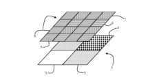
図1は、上述したような4つの静的偏光子部2を有するベイヤー画像センサ1の実施形態を示す。 FIG. 1 shows an embodiment of a
ベイヤー画像センサ1は、4つのカラーチャネル素子、赤色チャネル素子3、青色カラーチャネル素子4、および、2つの緑色チャネル素子5を有し、これらの素子は、矩形(二次)領域に配置され、ここで、2つの緑色チャネル素子5は、その点に関して、本開示を制限することなく、互いに対向して配置される。 The
各静的偏光子部2は、ゼロ度配線6を有するワイヤ-グリッド偏光子、45度配線7を有するワイヤ-グリッド偏光子、90度配線8を有するワイヤ-グリッド偏光子、および、135度配線9を有するワイヤ-グリッド偏光子を含む4つのワイヤ-グリッド偏光子を含む。 Each
例示の目的のみのために、静的偏光子部2は、ベイヤー画像センサ1上に積層されていないことが描かれている。しかしながら、議論されるように、いくつかの実施形態では、静的偏光子部は、カラーチャネル素子上に(直接的または間接的に)積層されてもよく、または、静的偏光子部は、少なくともカラーチャネル素子に十分に近接して設けられてもよく、その結果、光は、必要なカラーチャネル撮像素子に伝達され、偏光効果は無視され得る。 For illustrative purposes only, the
いくつかの実施形態では、各カラーチャネル素子に対して、第1のカラーチャネルのための平行偏光、第2のカラーチャネルのための矩形偏光など、本明細書で論じられるように、異なる偏光が提供される。 In some embodiments, for each color channel element a different polarization as discussed herein, such as parallel polarization for the first color channel and rectangular polarization for the second color channel. provided.
ベイヤー画像センサの場合、第1の緑色チャネルに対しては、45度の偏光を提供することができ、第2の緑色チャネルに対しては、90度の偏光を提供することができ、青色チャネルに対しては、0度の偏光を提供することができ、赤色チャネルに対しては、135度の偏光を提供することができる。 For a Bayer image sensor, 45 degree polarization can be provided for the first green channel, 90 degree polarization can be provided for the second green channel, and the blue channel 0 degrees of polarization can be provided for the red channel, and 135 degrees of polarization can be provided for the red channel.
連続した取得のために、他の偏光が、各カラーチャネル素子に対して提供されてもよい。 Other polarizations may be provided for each color channel element for sequential acquisition.
本開示は、ゼロ、45、90、および135度の偏光に限定されず、必要であれば、1、2、3、および4度などの偏光角が想定され得ることに注意すべきである。 It should be noted that the present disclosure is not limited to zero, 45, 90, and 135 degrees of polarization, and that polarization angles of 1, 2, 3, and 4 degrees, etc. can be assumed if desired.
一般に、偏光は各色チャネルについても同じであるか、少なくとも2色のチャネルについても同じである。 Generally, the polarization is the same for each color channel, or the same for at least two color channels.
いくつかの実施形態において、第1および第2の偏光の少なくとも1つは、上述のようなミュラー行列のような偏光マトリックスの要素を表し、ここで、本開示は、光の偏光子を記述する任意の数学的(または物理的)表現を採用することができるので、ミュラー行列の場合に限定されない。 In some embodiments, at least one of the first and second polarizations represents elements of a polarization matrix, such as the Mueller matrix as described above, where this disclosure describes a polarizer of light. It is not limited to Mueller matrices, as any mathematical (or physical) representation can be employed.
いくつかの実施形態では、偏光撮像システムは、第1のカラータイプの光を生成し、第2のカラータイプの光を生成するように構成された光源をさらに含む。 In some embodiments, the polarization imaging system further includes a light source configured to generate light of a first color type and to generate light of a second color type.
光源は、狭帯域光源、ダイオードレーザーなどのレーザー、(複数の)VCSEL(垂直キャビティ面発光レーザー)などを含んでもよい。さらに、異なる色のタイプを生成するために、例えば、異なる種類のダイオードが含まれてもよい。 The light source may comprise a narrowband light source, a laser such as a diode laser, VCSEL (Vertical Cavity Surface Emitting Laser(s)), and the like. Further, different types of diodes, for example, may be included to produce different color types.
さらに、光源は、広い帯域の(白色光)照明、例えば、可視範囲(例えば、400から780ナノメートル)によって実現され得る。 Further, the light source can be realized by broad band (white light) illumination, eg in the visible range (eg 400 to 780 nanometers).
光源により、対象物からの反射(偏光)光が本開示に従う撮像部によって検出され得るように、対象物を照らす、対象物に照射する等を行うことができる。 The light source can illuminate the object, irradiate the object, etc. such that reflected (polarized) light from the object can be detected by an imaging unit according to the present disclosure.
いくつかの実施形態では、偏光撮像システムは、生成された光に対して第1の偏光タイプの光源偏光を調整するように構成された偏光子をさらに含む。 In some embodiments, the polarized imaging system further includes a polarizer configured to adjust the light source polarization of the first polarization type to the generated light.
静的偏光子は、前述したように、同様の(静的または同調可能である)偏光子を指してもよく、そのような要素の繰り返しの記述は省略する。 A static polarizer may refer to a similar (either static or tunable) polarizer as previously described, and repeated descriptions of such elements are omitted.
それにより、対象物は、反射光が撮像部で検出可能であり得るように、光源偏光(または偏光タイプ)の光を照射され得る。 Thereby, the object may be illuminated with light of the light source polarization (or type of polarization) such that the reflected light may be detectable by the imager.
いくつかの実施形態では、第1のカラータイプの光の光源偏光は、第2のカラータイプの光と異なる。 In some embodiments, the light source polarization of the first color type of light is different than the second color type of light.
それにより、上述したように、各カラーチャンネルについて、それぞれの偏光を提供することができる。 Thereby, a respective polarization can be provided for each color channel, as described above.
いくつかの実施形態は、第1のカラータイプのカラーチャネル素子に対して第1の偏光タイプの第1の偏光を提供するステップと、第2のカラータイプのカラーチャネル素子に対して第1の偏光タイプの第2の偏光を提供するステップと、第2の偏光タイプを第1の偏光タイプに変換するステップとを含み、それによって、第2の偏光タイプは、本明細書で論じられるように、第1および第2のカラーチャネル素子を含む撮像部において検出可能である、偏光撮像方法に関する。 Some embodiments include providing a first polarization of a first polarization type to color channel elements of a first color type; providing a second polarization type of polarization and converting the second polarization type to the first polarization type, whereby the second polarization type is , to a polarization imaging method detectable in an imaging unit comprising first and second color channel elements.
この偏光撮像方法は、本開示による光源を制御し、それぞれの偏光を提供かつ/または変換するために本開示による同調可能な偏光子を制御し、時間調整するように構成された偏光制御回路によって実行されてもよい。 This polarization imaging method is performed by a polarization control circuit configured to control a light source according to the present disclosure and to control and time a tunable polarizer according to the present disclosure to provide and/or transform the respective polarization. may be executed.
このような偏光制御回路は、同調可能な偏光子(例えば、電流を流すことによる液晶変調器)の偏光特性を制御するように適合されてもよく、それぞれの偏光と偏光タイプを切り替えるように構成されてもよい。
スイッチ速度は、その点で本開示を制限することなく、kHzの範囲内であってもよい。さらに、偏光制御回路は、複数の同調可能な偏光子間のタイミングを制御するように構成されてもよい。Such polarization control circuitry may be adapted to control the polarization properties of tunable polarizers (e.g., liquid crystal modulators by passing a current through them), configured to switch between respective polarizations and polarization types. may be
The switching speed may be in the kHz range without limiting the disclosure in that respect. Further, the polarization control circuitry may be configured to control timing between multiple tunable polarizers.
いくつかの実施態様において、第1および第2の偏光タイプは、本明細書で説明するように、直線偏光および楕円偏光を含む。いくつかの実施形態において、画像撮影部は、本明細書で考察されるように、ベイヤー画像センサを含む。いくつかの実施形態では、ベイヤー画像センサは、本明細書で論じられるように、2つの緑色チャネル素子、赤色チャネル素子、および青色カラーチャネル素子を含む。
いくつかの実施形態において、各色チャネル素子について、本明細書で考察するように、異なる偏光子が提供される。いくつかの実施形態において、第1および第2の偏光子の少なくとも1つは、本明細書で考察されるように、偏光子行列の要素の代表である。いくつかの実施形態において、偏光マトリックスは、本明細書で考察されるように、ミュラー行列含む。
いくつかの実施形態において、偏光撮像方法は、本明細書で考察されるように、第1のカラータイプの光を発生させるステップと、第2のカラータイプの光を発生させるステップとをさらに含む。いくつかの実施形態では、偏光撮像部は、本明細書で論じられるように、生成された光に対して第1の偏光タイプの光源偏光を調整することを含む。In some embodiments, the first and second polarization types include linear polarization and elliptical polarization, as described herein. In some embodiments, the image capture component includes a Bayer image sensor, as discussed herein. In some embodiments, the Bayer image sensor includes two green channel elements, a red channel element and a blue color channel element as discussed herein.
In some embodiments, a different polarizer is provided as discussed herein for each color channel element. In some embodiments, at least one of the first and second polarizers is representative of elements of a polarizer matrix, as discussed herein. In some embodiments, the polarization matrix comprises a Mueller matrix, as discussed herein.
In some embodiments, the polarization imaging method further comprises generating light of a first color type and generating light of a second color type, as discussed herein. . In some embodiments, the polarization imager includes adjusting the light source polarization of the first polarization type to the generated light, as discussed herein.
本明細書に記載する方法は、コンピュータおよび/またはプロセッサ上で実行されるときに、コンピュータおよび/またはプロセッサに本開示の方法を実行させるコンピュータプログラムとして、いくつかの実施形態においても実施される。
いくつかの実施形態において、コンピュータプログラム製品を内部に保存する非一時的コンピュータ読取可能な記録媒体も提供され、これは、上記のプロセッサのようなプロセッサによって実行される場合、本明細書に記載された方法を実行させる。The methods described herein are also implemented in some embodiments as a computer program which, when run on a computer and/or processor, causes the computer and/or processor to perform the methods of the present disclosure.
In some embodiments, a non-transitory computer-readable medium storing therein a computer program product is also provided, which when executed by a processor, such as the processor described above, is described herein. method.
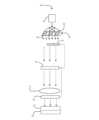
図2は、本開示による偏光撮像システム10の一実施形態をブロック図で示す。 FIG. 2 illustrates in block diagram form one embodiment of a
偏光撮像システム10は、対象物15上に3つの異なるカラーチャネル12、13、および14の光を放射するように構成された光源11を含む(偏光撮像システム10に必ずしも含まれないが、任意の種類の物体であってもよい)。 The
光源11と対象物15の間には、偏光子として第1の液晶変調回路16および第2の液晶変調回路17が配置されている。 A first liquid
第1の液晶変調回路16は、通過光に対して90度の固定偏光を提供するように適応されており、第2の液晶変調回路17は、その偏光特性においてスイッチング可能である、すなわち、第2の液晶変調回路17は、入射光に対してゼロ度または負の45度のいずれかの相シフトを適用するためにスイッチング可能である、双安定の液晶を含む。 The first liquid
さらに、偏光撮像システム10は、円偏光を直線偏光に変換するために、対象物15の後に、光路内に配置される第3の液晶変調回路18を含み、円偏光が、図1に関して説明したように、偏光子部20とともに積層された撮像部19内で(間接的に)検出され得る。 In addition, the
さらに、偏光撮像システム10は、液晶変調器17および18の偏光子特性を制御するように構成された偏光回路21を含み、偏光撮像システム10は、撮像部20内で生成された画像データを処理するための画像処理回路22をさらに含む。 Further, the
図3は、本開示による偏光撮像システム30のさらなる実施形態を描写し、光路内の同調可能な偏光子を制御するための例を与える。 FIG. 3 depicts a further embodiment of a
偏光撮像システム30は、ハロゲン元素(キセノン)光源31(上述のような広帯域光源)を含み、(非偏光)光を生成する。光は、ダイクロイック(2色性)・ビーム・スプリッタ・プリズム32上に導かれ、その後、光は偏光リサイクル・プリズム33を通過する。
ビーム・スプリッタ・プリズム32では、光は3つのカラーチャンネル、すなわち青、緑、および赤色(異なるハッチングで示す左から右への矢印)に分割される。 At
偏光リサイクル・プリズム33は、各カラーチャネルの強度の約半分が、それぞれの45度l/2波長板34を通過するように、各カラーチャネルの一部が方向転換されるように構成され、そのうちの3つ(各色チャネルに対して、換言すれば、各第2の出口に対して)が、偏光リサイクル・プリズム33の(光路に対して)後に配置される。 The
これにより、0度の各カラーチャネルの直線(リニア)偏光が生成される。 This produces linear polarization of each color channel at 0 degrees.
l/2波長板34と共に偏光リサイクル・プリズム33を使用することにより、偏光による光ロス(当該技術分野ではおよそ50パーセントであり得る)が最小化される。したがって、偏光リサイクリル・プリズムの使用は、この実施形態に限定されないが、他の実施形態においても同様に適用され得る。 By using a
例えば、本開示による偏光リサイクル・プリズムは、それぞれのアプリケーションで使用されるカラーチャネルの量に応じて、いくつかの出口を有していてもよく、出口のサブセットの後(またはそれぞれの出口の後)、l/2波長板が提供されてもよく、または、いくつかの実施形態において、1/2波長板が第2の出口ごとに提供されてもよい。 For example, a polarization recycling prism according to the present disclosure may have several exits, and after a subset of exits (or after each exit), depending on the amount of color channels used in each application. ), a half-wave plate may be provided, or in some embodiments a half-wave plate may be provided for each second outlet.
その後、第1の液晶変調回路35が配置され、これを通して緑色チャネルおよび赤色チャネルの光を通過させることができる。 A first liquid
さらに、各カラーチャネルのための第2の液晶変調回路36が、第1の液晶変調回路35の後に配置される。第1の液晶変調回路35と第2の液晶変調回路36とは、第1の液晶変調回路35の偏光特性が第2の液晶変調回路36の偏光特性に依存するように結合されている。それぞれの偏光は、上述のように、偏光制御回路(図示せず)によって制御されてもよい。 Furthermore, a second liquid
特に、第2の液晶変調回路36は、2つの配向、すなわち、ゼロ度および45度を有する広帯域l/4リターダを含む。配向ゼロ度が適用される場合、光の線形入力偏光が保持される。配向45度が適用される場合、直線偏光は円偏光に変換される。 In particular, the second liquid
さらに、第1の液晶変調回路35は、2つの切り替え可能なl/2波長板を含む。 Additionally, the first liquid
第2の液晶変調回路36が0度の配向に適合される場合、第1の液晶変調回路35は、緑色カラーチャネルを45度の直線偏光に、赤色カラーチャネルを90度の直線偏光に切り替えるように構成される。 When the second liquid
第2の液晶変調回路36が45度の配向に適合される場合、第1の液晶変調回路35は、すべてのカラーチャネルについて直線偏光をゼロ度に保つように構成される。 When the second liquid
これにより、十分な数の偏光状態が生成可能である。 A sufficient number of polarization states can thereby be generated.
さらに、第2の液晶変調回路36の後に、対象物37を配置することができ、ここで、対象物の後に、第3の液晶変調回路38が、2つの配向、すなわち、ゼロ度および45度を有する広帯域l/4リターダを含んで設けられる。 Furthermore, after the second liquid
第1の液晶変調回路35と同様に、第3の液晶変調回路38の偏光状態は、第2の液晶変調回路36に依存する。 As with the first liquid
第2の液晶変調回路36がゼロ度の配向に適応される場合、第3の液晶変調回路38は、同様にゼロ度の偏光配向を提供することによって、入ってくる光の直線偏光を維持するように構成されている。 When the second liquid
第2の液晶変調回路36が45度の配向度に適応される場合、すなわち、第2の液晶変調回路36において円偏光が生成される場合、第3の液晶変調回路38は、同様に45度の偏光配向度を提供することによって、円偏光(複数)を直線偏光(1以上)に変換するように構成されている。 If the second liquid
上述のように、それぞれの偏光は、偏光制御回路によって制御される。 As mentioned above, each polarization is controlled by a polarization control circuit.
第3の液晶変調器38の後に、図1に関して説明したように、撮像部40上に積層された偏光子部39が、本明細書で論じるように、各々入ってくる偏光状態の強度を読み取るために配置される。 After the third
このような構成では、4つの連続した画像フレーム(すなわち取得した画像フレーム)内で十分な偏光情報を取得することができ、ここでは、図4に関してここで議論するように、8フレーム内で十分な偏光情報を取得することが一般的に公知である。 With such a configuration, sufficient polarization information can be obtained within four consecutive image frames (i.e., acquired image frames), and here within eight frames, as discussed herein with respect to FIG. It is generally known to obtain such polarization information.
図4は、左側に4つの入射偏光状態、すなわち、光の電場の偏光を描写するために、その軸上に成分ExおよびEyを有するグラフで象徴的に描かれた、ゼロ度直線偏光、45度直線偏光、90度直線偏光、および右円偏光を描写している。 FIG. 4 is symbolically depicted on a graph with components Ex and Ey on its axis to depict the four incident polarization states on the left, namely the polarization of the electric field of light, zero degree linear polarization, 45 Degree linear polarization, 90 degree linear polarization, and right circular polarization are depicted.
従来技術では、各関連偏光状態は連続した8フレームで取得され、ここで、各秒フレームの後に、偏光カメラ46(本開示によれば、図1に関して論じられているように、ベイヤーセンサ上に積み重ねられた偏光子部を含むことができる)による取得の前に、波動遅延器45が利用される。 In the prior art, each relevant polarization state is acquired in 8 consecutive frames, where after each second frame, a polarization camera 46 (according to the present disclosure, on a Bayer sensor, as discussed with respect to FIG. 1). A
しかしながら、例えば、図3の偏光撮像システム30のような、本開示に従った偏光撮像システムを使用することによって、それぞれの偏光が色分けされるので、取得の総数は4に減少され得る。更に、直線偏光状態に関する完全な関連情報は、(従来技術における6つのフレームと比較して)2つのフレーム内で既に取得することができる。 However, by using a polarized imaging system according to the present disclosure, such as
図5は、本開示による偏光画像システムで得られた複数の測定結果50を示す。 FIG. 5 shows
左上には、RGB画像51が描出され(グレースケールで)、ここでは、血管52、筋組織53、および神経54がマークされている。 At the top left, an RGB image 51 is depicted (in greyscale), where blood vessels 52, muscle tissue 53 and nerves 54 are marked.
右上には、速軸配向偏光画像55が描かれている(その右側に強度スケールがある)。 At the top right is depicted a fast-axis oriented polarization image 55 (with an intensity scale to the right of it).
左下には、全偏光解消パワー偏光画像56が描かれている(その右側に強度スケールがある)。 At the bottom left, a fully depolarized power polarization image 56 is depicted (with an intensity scale to its right).
右下には、リニア遅延偏光画像57が示されている。 A linear delayed polarization image 57 is shown in the lower right.
図5からとることができるように、RGB画像51においてマークされている特徴は、他の画像55、56、および57においてより識別可能である。 As can be taken from FIG. 5, the features marked in the RGB image 51 are more discernible in the other images 55, 56 and 57. FIG.
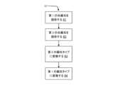
図6は、例えば、図3の偏光撮像システム30によって実行され得る、ブロック図における本開示による偏光撮像方法60を描写している。 FIG. 6 depicts a
61において、第1のカラータイプの第1のカラーチャネル素子に対する第1の偏光タイプの第1の光偏光が、本明細書で論じられるように、例えば緑色カラーチャネルに対して45度提供される。 At 61, a first light polarization of the first polarization type for the first color channel element of the first color type is provided at 45 degrees for the green color channel, for example, as discussed herein. .
62において、本明細書で論じられるように、第2のカラータイプの第2のカラーチャネル素子用の第1の偏光タイプの第2の光偏光が提供される。例えば、赤色カラーチャネル用の90度である。 At 62, a second light polarization of the first polarization type for the second color channel element of the second color type is provided, as discussed herein. For example, 90 degrees for the red color channel.
63において、第1および第2のカラーチャネルの光は、本明細書で論じるように、第2の偏光タイプに(例えば、円偏光で対象物(例えば、試料)を照射するための円偏光に)変換される。 At 63, the light of the first and second color channels is converted to a second polarization type (e.g., circularly polarized light for illuminating an object (e.g., sample) with circularly polarized light, as discussed herein). ) is converted.
64において、第2の偏光タイプである(試料からの)反射光は、第1の偏光タイプに変換され、それにより、ここで論じるように、この反射光は、撮像部において検出可能である。 At 64, the reflected light (from the sample) that is of the second polarization type is converted to the first polarization type so that it is detectable in the imaging section, as discussed herein.
図7は、本開示によるさらなる偏光撮像方法70を、光源の制御をさらに含むという点で、偏光撮像方法70とは異なるブロック図で示す。
偏光撮像方法70は、図3の偏光撮像システム30によって実行されてもよい。FIG. 7 illustrates a further
71は、本明細書で論じるように、第1のカラータイプの光が生成される(例えば、緑のカラータイプ)。 71 produces light of a first color type (eg, green color type) as discussed herein.
72では、本明細書で論じるように、第2のカラータイプの光が生成される(例えば、赤のカラータイプ)。 At 72, light of a second color type is generated (eg, red color type), as discussed herein.
73では、本明細書で論じられるように、例えば、図3に関して論じたように、偏光リサイクル・プリズムの後に波長板を有することによって、または、ソース偏光を適合させるために液晶変調回路を制御することによって、第1の偏光タイプのソース偏光が生成される。 At 73, control the liquid crystal modulation circuit to adapt the source polarization, as discussed herein, for example, by having a waveplate after the polarization recycling prism, as discussed with respect to FIG. This produces a first polarization type of source polarization.
74では、本明細書で論じられるように、第1のカラータイプの第1のカラーチャネル素子に対する第1の偏光タイプの第1の光偏光(例えば、緑色カラーチャネル用の45度)が提供される。 At 74, a first light polarization of a first polarization type (eg, 45 degrees for the green color channel) for a first color channel element of a first color type is provided, as discussed herein. be.
75では、本明細書で論じられるように、第2のカラータイプの第2のカラーチャネル素子に対する第1の偏光タイプの第2の光偏光(例えば、赤色カラーチャネル用の90度)が提供される。 At 75, a second light polarization of the first polarization type (e.g., 90 degrees for the red color channel) for the second color channel element of the second color type is provided, as discussed herein. be.
76では、第1および第2のカラーチャネルの光は、本明細書で論じるように、第2の偏光タイプに(例えば、円偏光で対象物(例えば、試料)を照射するための円偏光に)、変換される。 At 76, the light in the first and second color channels is converted to a second polarization type (e.g., circularly polarized light for illuminating an object (e.g., sample) with circularly polarized light, as discussed herein). ), to be converted.
77では、第2の偏光タイプである(試料からの反射)光は、本明細書で論じるように、第1の偏光タイプに変換され、それにより、この光は、撮像部で検出可能である。 At 77, light of the second polarization type (reflected from the sample) is converted to the first polarization type, as discussed herein, so that this light is detectable by the imager. .
上述した実施形態は、方法ステップの例示的な順序付けを伴う方法を説明していることを理解されたい。しかしながら、方法ステップの特定の順序付けは、例示のみを目的として与えられており、結合力のあるものとして解釈されるべきではない。例えば、図6の実施形態における61および62の順序は、交換され得るか、または並行して実行され得る。
また、図7の実施形態における71、72および73の順序が交換され得る。さらに、図7の実施形態における74および75の順序も交換され得る。方法ステップの順序の他の変更も、当業者には明らかであろう。It should be appreciated that the above-described embodiments describe methods with an exemplary ordering of method steps. However, the specific ordering of method steps is provided for illustrative purposes only and should not be construed as binding. For example, the order of 61 and 62 in the embodiment of Figure 6 can be interchanged or performed in parallel.
Also, the order of 71, 72 and 73 in the embodiment of FIG. 7 can be interchanged. Additionally, the order of 74 and 75 in the embodiment of FIG. 7 may also be interchanged. Other permutations of the order of method steps will be apparent to those skilled in the art.
偏光撮像システム10をユニット21およびユニット22に分割することは、例示目的のためにのみなされるものであり、本開示は特定のユニットにおける機能の特定の分割に限定されないことに留意されたい。
例えば、これらの構成要件21および22は、それぞれのプログラム化された処理装置、フィールドプログラマブルゲートアレイ(FPGA)等によって実装することができる。Note that the division of
For example, these
また、この方法は、コンピュータおよび/またはプロセッサ上で実装される場合に、上述した偏光回路21のようなコンピュータおよび/またはプロセッサに、この方法を実行させるコンピュータプログラムとして実装され得る。
いくつかの実施形態において、コンピュータプログラム製品内に保存する非一時的なコンピュータ読み取り可能な記録媒体も提供され、これは、上記のプロセッサのようなプロセッサによって実行されると、上記の方法を実行させる。Also, the method can be implemented as a computer program that, when implemented on a computer and/or processor, causes the computer and/or processor, such as the
In some embodiments, a non-transitory computer-readable medium for storage in a computer program product is also provided, which when executed by a processor, such as the processor described above, causes the method described above to be performed. .
本明細書に記載され、添付の特許請求の範囲に請求されるすべてのユニットおよびエンティティは別段の記載がない限り、例えばチップ上の集積回路ロジックとして実装することができ、そのようなユニットおよびエンティティによって提供される機能は、別段の記載がない限り、ソフトウェアによって実装することができる。 All units and entities described in this specification and claimed in the appended claims may be implemented, for example, as integrated circuit logic on a chip, and such units and entities may be implemented as integrated circuit logic on a chip, unless stated otherwise. The functionality provided by may be implemented by software unless otherwise stated.
上述の本開示の実施形態が少なくとも部分的に、ソフトウェア制御されたデータ処理装置を使用して実施される限り、そのようなソフトウェア制御を提供するコンピュータプログラム、および、そのようなコンピュータプログラムが提供される伝送、記憶、または他の媒体が、本開示の態様として想定されることが理解される。 To the extent that the above-described embodiments of the present disclosure are at least partially implemented using a software-controlled data processing apparatus, a computer program providing such software control and such a computer program are provided. It is understood that any transmission, storage, or other medium of transmission is contemplated as an aspect of this disclosure.
なお、本技術は以下のような構成も取ることができる。
(1) 第1のカラータイプのカラーチャネル素子、および、第2のカラータイプのカラーチャネル素子を有する撮像部と、
前記第1のカラータイプに対して第1の偏光タイプの第1の光偏光を提供し、前記第2のカラータイプに対して前記第1の偏光タイプの第2の光偏光を提供し、かつ、
第2の偏光タイプを前記第1の偏光タイプに変換し、それによって、前記第2の偏光タイプが前記撮像部において検出可能である
ように構成された光偏光部と
を具備する
偏光撮像システム。
(2) 前記第2の偏光タイプを前記第1の偏光タイプに変換するための少なくとも1つの波長可変偏光子をさらに含む
(1)に記載の偏光撮像システム。
(3) 前記第1の偏光タイプおよび前記第2の偏光タイプは、リニア偏光および楕円偏光を含む
(1)および(2)のいずれか1つに記載の偏光撮像システム。
(4) 前記撮像部は、ベイヤー画像センサを含む
(1)から(3)のいずれか1つに記載の偏光撮像システム。
(5) 前記ベイヤー画像センサは、2つの緑色チャネル素子、赤色チャネル素子、および青色チャネル素子を含む
(4)に記載の偏光撮像システム。
(6) 各カラーチャネル素子に対して、異なる偏光が提供されている
(5)に記載の偏光撮像システム。
(7) 前記第1の偏光および第2の偏光のうちの少なくとも1つは、偏光マトリクスの要素を表す
(1)から(6)のいずれか1つに記載の偏光撮像システム。
(8) 前記偏光マトリクスは、ミュラー行列を含む
(7)に記載の偏光撮像システム。
(9) 前記第1のカラータイプの光を生成し、前記第2のカラータイプの光を生成するように構成された光源をさらに含む
(1)から(8)のいずれか1つに記載の偏光撮像システム。
(10) 前記生成された光に対して前記第1の偏光タイプの光源偏光を調整するように構成された偏光子をさらに含む
(9)に記載の偏光撮像システム。
(11) 前記第1のカラータイプの光の光源偏光は、前記第2のカラータイプの光と異なる
(10)に記載の偏光撮像システム。
(12) 第1のカラータイプのカラーチャネル素子に対して第1の偏光タイプの第1の光偏光を提供するステップと、
第2のカラータイプのカラーチャネル素子に対して前記第1の偏光タイプの第2の光偏光を提供するステップと、
第2の偏光タイプを前記第1の偏光タイプに変換するステップと
を含み、
それによって、前記第2の偏光タイプは、前記第1のカラーチャネル素子および前記第2のカラーチャネル素子を含む撮像部において検出可能である
偏光撮像方法。
(13) 前記第1の偏光タイプおよび第2の偏光タイプは、リニア偏光および楕円偏光を含む
(12)に記載の偏光撮像方法。
(14) 前記撮像部は、ベイヤー画像センサを含む
(12)および(13)のいずれかに記載の偏光撮像方法。
(15) 前記ベイヤー画像センサは、2つの緑色チャネル素子、赤色チャネル素子、および青色チャネル素子を含む
(14)に記載の偏光撮像方法。
(16) 各カラーチャネル素子に対して、異なる偏光が提供される
(15)に記載の偏光撮像方法。
(17) 前記第1の偏光および第2の偏光のうちの少なくとも1つは、偏光マトリクスの要素を表す
(12)から(16)のいずれか1つに記載の偏光撮像方法。
(18) 前記偏光マトリクスは、ミュラー行列を含む
(17)に記載の偏光撮像方法。
(19) 前記第1のカラータイプの光を生成するステップと、
前記第2のカラータイプの光を生成するステップと、
をさらに含む
(12)から(18)のいずれか1つに記載の偏光撮像方法。
(20) 前記生成された光に対して前記第1の偏光タイプの光源偏光を調整するステップをさらに含む
(19)に記載の偏光撮像方法。
(21) コンピュータ上で実行されるときに、前記コンピュータに、(11)から(20)のいずれか1つに記載の方法を実行させるプログラムコードを具備する
コンピュータプログラム。
(22) プロセッサによって実行されるときに、(11)から(20)のいずれか1つに記載の方法を実行させるコンピュータプログラム製品を内部に保存する非一時的コンピュータ読取可能な記録媒体。Note that the present technology can also take the following configuration.
(1) an imaging unit having a first color type color channel element and a second color type color channel element;
providing a first light polarization of a first polarization type for said first color type, providing a second light polarization of said first polarization type for said second color type, and ,
A polarized imaging system, comprising: a light polarizer configured to convert a second polarization type to said first polarization type, whereby said second polarization type is detectable at said imaging unit.
(2) further comprising at least one tunable polarizer for converting said second polarization type to said first polarization type;
(1) The polarization imaging system according to (1).
(3) the first polarization type and the second polarization type include linear polarization and elliptical polarization;
The polarization imaging system according to any one of (1) and (2).
(4) The imaging unit includes a Bayer image sensor
The polarization imaging system according to any one of (1) to (3).
(5) the Bayer image sensor includes two green channel elements, a red channel element and a blue channel element;
(4) The polarization imaging system according to (4).
(6) Different polarizations are provided for each color channel element
The polarization imaging system according to (5).
(7) at least one of said first and second polarizations represents an element of a polarization matrix;
The polarization imaging system according to any one of (1) to (6).
(8) the polarization matrix includes a Mueller matrix
The polarization imaging system according to (7).
(9) further comprising a light source configured to generate light of said first color type and to generate light of said second color type;
The polarization imaging system according to any one of (1) to (8).
(10) further comprising a polarizer configured to adjust the light source polarization of the first polarization type with respect to the generated light;
(9) The polarization imaging system according to (9).
(11) the light source polarization of said first color type light is different from said second color type light;
(10) The polarization imaging system according to (10).
(12) providing a first light polarization of a first polarization type to a color channel element of a first color type;
providing a second light polarization of said first polarization type to color channel elements of a second color type;
converting a second polarization type to said first polarization type;
A polarization imaging method whereby said second polarization type is detectable in an imaging unit comprising said first color channel element and said second color channel element.
(13) the first polarization type and the second polarization type include linear polarization and elliptical polarization
(12) The polarization imaging method according to (12).
(14) The imaging unit includes a Bayer image sensor
(12) The polarization imaging method according to any one of (12) and (13).
(15) the Bayer image sensor includes two green channel elements, a red channel element and a blue channel element;
(14) The polarization imaging method according to (14).
(16) A different polarization is provided for each color channel element
(15) The polarization imaging method according to (15).
(17) at least one of the first polarization and the second polarization represents an element of a polarization matrix;
The polarization imaging method according to any one of (12) to (16).
(18) The polarization matrix includes a Mueller matrix
(17) The polarization imaging method according to (17).
(19) generating light of said first color type;
generating light of said second color type;
further includes
The polarization imaging method according to any one of (12) to (18).
(20) further comprising adjusting a light source polarization of said first polarization type for said generated light;
(19) The polarization imaging method according to (19).
(21) A computer program comprising program code that, when run on a computer, causes said computer to perform the method of any one of (11) to (20).
(22) A non-transitory computer-readable recording medium storing therein a computer program product that, when executed by a processor, causes the method of any one of (11) to (20) to be performed.
Claims (20)
Translated fromJapanese前記第1のカラータイプに対して第1の偏光タイプの第1の光偏光を提供し、前記第2のカラータイプに対して前記第1の偏光タイプの第2の光偏光を提供し、かつ、
第2の偏光タイプを前記第1の偏光タイプに変換し、それによって、前記第2の偏光タイプが前記撮像部において検出可能である
ように構成された光偏光部と
を具備する
偏光撮像システム。an imaging unit having a first color type color channel element and a second color type color channel element;
providing a first light polarization of a first polarization type for said first color type, providing a second light polarization of said first polarization type for said second color type, and ,
A polarized imaging system, comprising: a light polarizer configured to convert a second polarization type to said first polarization type, whereby said second polarization type is detectable at said imaging unit.
請求項1に記載の偏光撮像システム。2. The polarized imaging system of Claim 1, further comprising at least one tunable polarizer for converting said second polarization type to said first polarization type.
請求項1に記載の偏光撮像システム。2. The polarized imaging system of claim 1, wherein the first polarization type and the second polarization type include linear polarization and elliptical polarization.
請求項1に記載の偏光撮像システム。2. The polarization imaging system of claim 1, wherein the imager includes a Bayer image sensor.
請求項4に記載の偏光撮像システム。5. The polarization imaging system of claim 4, wherein the Bayer image sensor includes two green channel elements, a red channel element and a blue channel element.
請求項5に記載の偏光撮像システム。6. The polarization imaging system of claim 5, wherein different polarizations are provided for each color channel element.
請求項1に記載の偏光撮像システム。2. The polarized imaging system of claim 1, wherein at least one of the first polarization and the second polarization represent elements of a polarization matrix.
請求項7に記載の偏光撮像システム。8. The polarization imaging system of Claim 7, wherein the polarization matrix comprises a Mueller matrix.
請求項1に記載の偏光撮像システム。2. The polarized imaging system of Claim 1, further comprising a light source configured to generate said first color type of light and to generate said second color type of light.
請求項9に記載の偏光撮像システム。10. The polarized imaging system of Claim 9, further comprising a polarizer configured to adjust a light source polarization of said first polarization type to said generated light.
請求項10に記載の偏光撮像システム。11. The polarized imaging system of claim 10, wherein a source polarization of said first color type light is different than said second color type light.
第2のカラータイプのカラーチャネル素子に対して前記第1の偏光タイプの第2の光偏光を提供するステップと、
第2の偏光タイプを前記第1の偏光タイプに変換するステップと
を含み、
それによって、前記第2の偏光タイプは、前記第1のカラーチャネル素子および前記第2のカラーチャネル素子を含む撮像部において検出可能である
偏光撮像方法。providing a first light polarization of a first polarization type to the color channel elements of the first color type;
providing a second light polarization of said first polarization type to color channel elements of a second color type;
converting a second polarization type to said first polarization type;
A polarization imaging method whereby said second polarization type is detectable in an imaging unit comprising said first color channel element and said second color channel element.
請求項12に記載の偏光撮像方法。13. The polarized imaging method of claim 12, wherein the first polarization type and second polarization type include linear polarization and elliptical polarization.
請求項12に記載の偏光撮像方法。The polarization imaging method according to claim 12, wherein the imaging unit includes a Bayer image sensor.
請求項14に記載の偏光撮像方法。15. The polarization imaging method of claim 14, wherein the Bayer image sensor includes two green channel elements, a red channel element and a blue channel element.
請求項15に記載の偏光撮像方法。16. The polarization imaging method of claim 15, wherein a different polarization is provided for each color channel element.
請求項12に記載の偏光撮像方法。13. The polarization imaging method of claim 12, wherein at least one of the first polarization and the second polarization represents elements of a polarization matrix.
請求項17に記載の偏光撮像方法。18. The polarization imaging method of claim 17, wherein the polarization matrix comprises a Mueller matrix.
前記第2のカラータイプの光を生成するステップと、
をさらに含む
請求項12に記載の偏光撮像方法。generating light of said first color type;
generating light of said second color type;
13. The polarization imaging method of claim 12, further comprising:
請求項19に記載の偏光撮像方法。20. The polarized imaging method of Claim 19, further comprising adjusting a light source polarization of said first polarization type for said generated light.
Applications Claiming Priority (3)
| Application Number | Priority Date | Filing Date | Title |
|---|---|---|---|
| EP19219840 | 2019-12-27 | ||
| EP19219840.6 | 2019-12-27 | ||
| PCT/EP2020/087620WO2021130222A1 (en) | 2019-12-27 | 2020-12-22 | Polarization imaging system and polarization imaging method |
Publications (1)
| Publication Number | Publication Date |
|---|---|
| JP2023509867Atrue JP2023509867A (en) | 2023-03-10 |
Family
ID=69055757
Family Applications (1)
| Application Number | Title | Priority Date | Filing Date |
|---|---|---|---|
| JP2022538903APendingJP2023509867A (en) | 2019-12-27 | 2020-12-22 | Polarization imaging system and polarization imaging method |
Country Status (4)
| Country | Link |
|---|---|
| US (1) | US12320741B2 (en) |
| EP (1) | EP4081846A1 (en) |
| JP (1) | JP2023509867A (en) |
| WO (1) | WO2021130222A1 (en) |
Families Citing this family (3)
| Publication number | Priority date | Publication date | Assignee | Title |
|---|---|---|---|---|
| CN112444508B (en)* | 2019-09-03 | 2024-12-17 | 天马日本株式会社 | Fluorescent image analysis device |
| WO2024085221A1 (en)* | 2022-10-20 | 2024-04-25 | 富士フイルム株式会社 | Blood flow measurement device |
| CN115790849A (en)* | 2023-02-08 | 2023-03-14 | 长春理工大学 | Intelligent regulation and control type multispectral polarization imaging device and method |
Citations (12)
| Publication number | Priority date | Publication date | Assignee | Title |
|---|---|---|---|---|
| JPH05142141A (en)* | 1991-11-19 | 1993-06-08 | Katsuya Masao | Thin film measuring instrument |
| JP2003035613A (en)* | 2001-07-23 | 2003-02-07 | Omron Corp | Residual stress inspection device for light pervious substance |
| JP2004062178A (en)* | 2002-06-28 | 2004-02-26 | Sharp Corp | Polarization rotators, parallax barriers, displays and optical modulators |
| WO2012002207A1 (en)* | 2010-06-29 | 2012-01-05 | 国立大学法人京都工芸繊維大学 | Method and apparatus for polarization imaging |
| JP2013505459A (en)* | 2009-09-22 | 2013-02-14 | ヴォロテック・リミテッド | Navigation apparatus and method |
| US20130307950A1 (en)* | 2011-01-31 | 2013-11-21 | Mustech Computing Services Ltd. | Optical polarimetric imaging |
| JP2015227827A (en)* | 2014-06-02 | 2015-12-17 | 横河電機株式会社 | Polarization inspection equipment |
| WO2017099253A1 (en)* | 2015-12-11 | 2017-06-15 | 株式会社ニコン | Polarization property image measurement device and polarization property image measurement method |
| WO2018003359A1 (en)* | 2016-07-01 | 2018-01-04 | 富士フイルム株式会社 | Laminate color filter, kit, laminate color filter manufacturing method and optical sensor |
| JP2019075703A (en)* | 2017-10-17 | 2019-05-16 | 平本 政夫 | Polarization imaging apparatus |
| WO2019176209A1 (en)* | 2018-03-13 | 2019-09-19 | ソニーセミコンダクタソリューションズ株式会社 | Solid-state imaging device |
| JP2019184977A (en)* | 2018-04-17 | 2019-10-24 | 株式会社ジャパンディスプレイ | Electro-optic device |
Family Cites Families (12)
| Publication number | Priority date | Publication date | Assignee | Title |
|---|---|---|---|---|
| JPH11281944A (en)* | 1998-03-31 | 1999-10-15 | Nec Eng Ltd | Optical attenuator, optical transmission system, and reception part |
| US6522407B2 (en) | 1999-01-22 | 2003-02-18 | The Regents Of The University Of California | Optical detection dental disease using polarized light |
| US7420675B2 (en) | 2003-06-25 | 2008-09-02 | The University Of Akron | Multi-wavelength imaging system |
| US7289211B1 (en) | 2004-04-09 | 2007-10-30 | Walsh Jr Joseph T | System and method for imaging sub-surface polarization-sensitive material structures |
| US7285767B2 (en)* | 2005-10-24 | 2007-10-23 | General Electric Company | Methods and apparatus for inspecting an object |
| US8004675B2 (en)* | 2007-09-20 | 2011-08-23 | Boss Nova Technologies, LLC | Method and system for stokes polarization imaging |
| JP5587057B2 (en) | 2010-06-29 | 2014-09-10 | 富士フイルム株式会社 | Polarized image measurement device and polarized image measurement display system |
| US8804122B2 (en)* | 2011-09-22 | 2014-08-12 | Brightex Bio-Photonics Llc | Systems and methods for determining a surface profile using a plurality of light sources |
| JP6422924B2 (en)* | 2016-09-12 | 2018-11-14 | 株式会社ソニー・インタラクティブエンタテインメント | Imaging apparatus and subject information acquisition method |
| WO2019051301A1 (en) | 2017-09-08 | 2019-03-14 | Arizona Board Of Regents On Behalf Of The University Of Arizona | Polarization and phase microscope |
| EP3667299B1 (en)* | 2018-12-13 | 2022-11-09 | Imec VZW | Multimodal imaging system |
| KR102803339B1 (en)* | 2020-11-10 | 2025-05-07 | 삼성전자주식회사 | Wearable electronic device comprising display |
- 2020
- 2020-12-22JPJP2022538903Apatent/JP2023509867A/enactivePending
- 2020-12-22WOPCT/EP2020/087620patent/WO2021130222A1/ennot_activeCeased
- 2020-12-22EPEP20824957.3Apatent/EP4081846A1/enactivePending
- 2020-12-22USUS17/786,545patent/US12320741B2/enactiveActive
Patent Citations (13)
| Publication number | Priority date | Publication date | Assignee | Title |
|---|---|---|---|---|
| JPH05142141A (en)* | 1991-11-19 | 1993-06-08 | Katsuya Masao | Thin film measuring instrument |
| US5910841A (en)* | 1991-11-19 | 1999-06-08 | Masao; Katsuya | Ellipsometer using an expanded beam |
| JP2003035613A (en)* | 2001-07-23 | 2003-02-07 | Omron Corp | Residual stress inspection device for light pervious substance |
| JP2004062178A (en)* | 2002-06-28 | 2004-02-26 | Sharp Corp | Polarization rotators, parallax barriers, displays and optical modulators |
| JP2013505459A (en)* | 2009-09-22 | 2013-02-14 | ヴォロテック・リミテッド | Navigation apparatus and method |
| WO2012002207A1 (en)* | 2010-06-29 | 2012-01-05 | 国立大学法人京都工芸繊維大学 | Method and apparatus for polarization imaging |
| US20130307950A1 (en)* | 2011-01-31 | 2013-11-21 | Mustech Computing Services Ltd. | Optical polarimetric imaging |
| JP2015227827A (en)* | 2014-06-02 | 2015-12-17 | 横河電機株式会社 | Polarization inspection equipment |
| WO2017099253A1 (en)* | 2015-12-11 | 2017-06-15 | 株式会社ニコン | Polarization property image measurement device and polarization property image measurement method |
| WO2018003359A1 (en)* | 2016-07-01 | 2018-01-04 | 富士フイルム株式会社 | Laminate color filter, kit, laminate color filter manufacturing method and optical sensor |
| JP2019075703A (en)* | 2017-10-17 | 2019-05-16 | 平本 政夫 | Polarization imaging apparatus |
| WO2019176209A1 (en)* | 2018-03-13 | 2019-09-19 | ソニーセミコンダクタソリューションズ株式会社 | Solid-state imaging device |
| JP2019184977A (en)* | 2018-04-17 | 2019-10-24 | 株式会社ジャパンディスプレイ | Electro-optic device |
Also Published As
| Publication number | Publication date |
|---|---|
| US12320741B2 (en) | 2025-06-03 |
| WO2021130222A1 (en) | 2021-07-01 |
| US20230034139A1 (en) | 2023-02-02 |
| EP4081846A1 (en) | 2022-11-02 |
Similar Documents
| Publication | Publication Date | Title |
|---|---|---|
| JP7296437B2 (en) | Surgical system including non-white light general illuminator | |
| JP2023509867A (en) | Polarization imaging system and polarization imaging method | |
| CN107137053B (en) | Medical examination device such as microscope or endoscope using pseudo-color | |
| US11474334B2 (en) | Observation device and observation method | |
| US8792098B2 (en) | System and method for hyperspectral illumination | |
| US20180224333A1 (en) | Image capturing apparatus and image capturing computer program product | |
| US10999569B2 (en) | Three-dimensional image reconstruction using multi-layer data acquisition | |
| US10205888B2 (en) | Endoscope system | |
| US20160057325A1 (en) | Camera having light emitting device, method for imaging skin and method for detecting skin condition using the same | |
| CN111492296A (en) | Fluorescence microscope device and fluorescence microscope system | |
| US8803959B2 (en) | Polarization observation device | |
| KR101632067B1 (en) | Hyperspectral imaging system | |
| CN115191915A (en) | An endoscope imaging system | |
| WO2023105242A1 (en) | Polarimetric endoscopy | |
| Fernández et al. | Real-time polarimetric microscopy of biological tissue | |
| JPH07323014A (en) | Skin surface observation device | |
| Kagawa et al. | Variable field-of-view visible and near-infrared polarization compound-eye endoscope | |
| Fernández et al. | Real-time Mueller matrix imaging of biological tissue | |
| US11412204B2 (en) | Three-dimensional image reconstruction using multi-layer data acquisition | |
| EP4392760A1 (en) | Device and method for polarimetric imaging | |
| US20230421912A1 (en) | Systems and methods for multi-spectral imaging with a non-mechanical adjustable aperture | |
| KR20190138169A (en) | Method and device for imaging of retina | |
| Bai et al. | Single-shot computational polarized light microscopy for imaging of pathological crystals | |
| JP2025519038A (en) | Method, processor and medical fluorescence observation device using color-dependent color transformation functions - Patents.com | |
| Blain et al. | Comparison of spectral colorimetric measurements vs. color pictures in dermatology |
Legal Events
| Date | Code | Title | Description |
|---|---|---|---|
| A621 | Written request for application examination | Free format text:JAPANESE INTERMEDIATE CODE: A621 Effective date:20230926 | |
| A977 | Report on retrieval | Free format text:JAPANESE INTERMEDIATE CODE: A971007 Effective date:20240930 | |
| A131 | Notification of reasons for refusal | Free format text:JAPANESE INTERMEDIATE CODE: A131 Effective date:20241015 | |
| A521 | Request for written amendment filed | Free format text:JAPANESE INTERMEDIATE CODE: A523 Effective date:20241216 | |
| A131 | Notification of reasons for refusal | Free format text:JAPANESE INTERMEDIATE CODE: A131 Effective date:20250318 | |
| A521 | Request for written amendment filed | Free format text:JAPANESE INTERMEDIATE CODE: A523 Effective date:20250519 | |
| A131 | Notification of reasons for refusal | Free format text:JAPANESE INTERMEDIATE CODE: A131 Effective date:20250902 | |
| A521 | Request for written amendment filed | Free format text:JAPANESE INTERMEDIATE CODE: A523 Effective date:20250909 |