JP2023509000A - Photoacoustic detector or photothermal detector with optical transducer - Google Patents
Photoacoustic detector or photothermal detector with optical transducerDownload PDFInfo
- Publication number
- JP2023509000A JP2023509000AJP2022539400AJP2022539400AJP2023509000AJP 2023509000 AJP2023509000 AJP 2023509000AJP 2022539400 AJP2022539400 AJP 2022539400AJP 2022539400 AJP2022539400 AJP 2022539400AJP 2023509000 AJP2023509000 AJP 2023509000A
- Authority
- JP
- Japan
- Prior art keywords
- waveguide
- medium
- transducer
- membrane
- modulation
- Prior art date
- Legal status (The legal status is an assumption and is not a legal conclusion. Google has not performed a legal analysis and makes no representation as to the accuracy of the status listed.)
- Granted
Links
Images


Classifications
- G—PHYSICS
- G01—MEASURING; TESTING
- G01N—INVESTIGATING OR ANALYSING MATERIALS BY DETERMINING THEIR CHEMICAL OR PHYSICAL PROPERTIES
- G01N21/00—Investigating or analysing materials by the use of optical means, i.e. using sub-millimetre waves, infrared, visible or ultraviolet light
- G01N21/17—Systems in which incident light is modified in accordance with the properties of the material investigated
- G01N21/1702—Systems in which incident light is modified in accordance with the properties of the material investigated with opto-acoustic detection, e.g. for gases or analysing solids
- G—PHYSICS
- G01—MEASURING; TESTING
- G01N—INVESTIGATING OR ANALYSING MATERIALS BY DETERMINING THEIR CHEMICAL OR PHYSICAL PROPERTIES
- G01N21/00—Investigating or analysing materials by the use of optical means, i.e. using sub-millimetre waves, infrared, visible or ultraviolet light
- G01N21/17—Systems in which incident light is modified in accordance with the properties of the material investigated
- G01N21/171—Systems in which incident light is modified in accordance with the properties of the material investigated with calorimetric detection, e.g. with thermal lens detection
- G—PHYSICS
- G01—MEASURING; TESTING
- G01N—INVESTIGATING OR ANALYSING MATERIALS BY DETERMINING THEIR CHEMICAL OR PHYSICAL PROPERTIES
- G01N21/00—Investigating or analysing materials by the use of optical means, i.e. using sub-millimetre waves, infrared, visible or ultraviolet light
- G01N21/17—Systems in which incident light is modified in accordance with the properties of the material investigated
- G01N21/1717—Systems in which incident light is modified in accordance with the properties of the material investigated with a modulation of one or more physical properties of the sample during the optical investigation, e.g. electro-reflectance
- G—PHYSICS
- G01—MEASURING; TESTING
- G01N—INVESTIGATING OR ANALYSING MATERIALS BY DETERMINING THEIR CHEMICAL OR PHYSICAL PROPERTIES
- G01N21/00—Investigating or analysing materials by the use of optical means, i.e. using sub-millimetre waves, infrared, visible or ultraviolet light
- G01N21/17—Systems in which incident light is modified in accordance with the properties of the material investigated
- G01N21/25—Colour; Spectral properties, i.e. comparison of effect of material on the light at two or more different wavelengths or wavelength bands
- G01N21/31—Investigating relative effect of material at wavelengths characteristic of specific elements or molecules, e.g. atomic absorption spectrometry
- G—PHYSICS
- G01—MEASURING; TESTING
- G01N—INVESTIGATING OR ANALYSING MATERIALS BY DETERMINING THEIR CHEMICAL OR PHYSICAL PROPERTIES
- G01N21/00—Investigating or analysing materials by the use of optical means, i.e. using sub-millimetre waves, infrared, visible or ultraviolet light
- G01N21/17—Systems in which incident light is modified in accordance with the properties of the material investigated
- G01N21/1702—Systems in which incident light is modified in accordance with the properties of the material investigated with opto-acoustic detection, e.g. for gases or analysing solids
- G01N2021/1704—Systems in which incident light is modified in accordance with the properties of the material investigated with opto-acoustic detection, e.g. for gases or analysing solids in gases
- G—PHYSICS
- G01—MEASURING; TESTING
- G01N—INVESTIGATING OR ANALYSING MATERIALS BY DETERMINING THEIR CHEMICAL OR PHYSICAL PROPERTIES
- G01N21/00—Investigating or analysing materials by the use of optical means, i.e. using sub-millimetre waves, infrared, visible or ultraviolet light
- G01N21/17—Systems in which incident light is modified in accordance with the properties of the material investigated
- G01N21/1702—Systems in which incident light is modified in accordance with the properties of the material investigated with opto-acoustic detection, e.g. for gases or analysing solids
- G01N2021/1706—Systems in which incident light is modified in accordance with the properties of the material investigated with opto-acoustic detection, e.g. for gases or analysing solids in solids
- G—PHYSICS
- G01—MEASURING; TESTING
- G01N—INVESTIGATING OR ANALYSING MATERIALS BY DETERMINING THEIR CHEMICAL OR PHYSICAL PROPERTIES
- G01N21/00—Investigating or analysing materials by the use of optical means, i.e. using sub-millimetre waves, infrared, visible or ultraviolet light
- G01N21/17—Systems in which incident light is modified in accordance with the properties of the material investigated
- G01N21/1717—Systems in which incident light is modified in accordance with the properties of the material investigated with a modulation of one or more physical properties of the sample during the optical investigation, e.g. electro-reflectance
- G01N2021/1731—Temperature modulation
Landscapes
- Physics & Mathematics (AREA)
- Biochemistry (AREA)
- General Physics & Mathematics (AREA)
- Life Sciences & Earth Sciences (AREA)
- Chemical & Material Sciences (AREA)
- Analytical Chemistry (AREA)
- Pathology (AREA)
- General Health & Medical Sciences (AREA)
- Health & Medical Sciences (AREA)
- Immunology (AREA)
- Spectroscopy & Molecular Physics (AREA)
- Investigating Or Analyzing Materials By The Use Of Ultrasonic Waves (AREA)
- Investigating Or Analysing Materials By Optical Means (AREA)
- Investigating Or Analyzing Materials Using Thermal Means (AREA)
- Light Receiving Elements (AREA)
Abstract
Translated fromJapanese
Description
Translated fromJapanese本発明の技術分野は、光音響検出または光熱検出の原理による媒体中の分析物の検出である。 The technical field of the invention is the detection of analytes in media by the principle of photoacoustic or photothermal detection.
光音響検出は、励起波と呼ばれるパルスまたは振幅変調された励起電磁波の分析媒体による吸収の影響下で発生した音波の検出に基づく。音波は、分析媒体中に存在する吸収性分子の励起波の吸収の影響下で加熱後に形成される。この加熱は、媒体の変調された熱膨張をもたらし、この膨張が音波の起源となる。 Photoacoustic detection is based on the detection of sound waves generated under the influence of absorption by the analysis medium of a pulsed or amplitude-modulated excitation electromagnetic wave, called the excitation wave. Acoustic waves are formed after heating under the influence of absorption of the excitation wave by absorbing molecules present in the analytical medium. This heating results in a modulated thermal expansion of the medium, which is the origin of sound waves.
光音響検出は、励起波の波長を分析物の吸収波長に設定することによって、1つの特定の分析物に特異的にすることができる。光音響検出はガス中のガス種の検出または生体組織中の特定分子の存在の検出に応用されている。入射波の波長はしばしば赤外に位置する。 Photoacoustic detection can be made specific to one particular analyte by setting the wavelength of the excitation wave to the absorbance wavelength of the analyte. Photoacoustic detection has been applied to the detection of gas species in gases or the presence of specific molecules in living tissue. The wavelength of the incident wave is often located in the infrared.
光音響検出は、次いで、散乱または不透明媒体に適用され得る非侵襲的分析技術である。 Photoacoustic detection is a non-invasive analytical technique that can then be applied to scattering or opaque media.
光音響検出の生体組織への適用は、例えば、以下の刊行物に記載されている。
-Bauer AJ. “IR-spectroscopy for skin in vivo: Optimal skin sites and properties for non-invasive glucose measurement by photoacoustic and photothermal spectroscopy”;Journal of Biopohtonics 11 (2018)
-“Windowless ultrasound photoacoustic cell for in-vivo mid-IR spectroscopy of human epidermis: Low interference by changes of air pressure, temperature, and humidity caused by skin contact opens the possibility for a non-invasive monitoring glucose in the interstitial fluid””; Rev.Sci.Instrum.84, 084901 (2013)Application of photoacoustic detection to living tissue is described, for example, in the following publications.
- Bauer AJ. “IR-spectroscopy for skin in vivo: Optimal skin sites and properties for non-invasive glucose measurement by photoacoustic and photothermal spectroscopy”; Journal of Biopohtonics 11 (2018)
-“Windowless ultrasound photoacoustic cell for in-vivo mid-IR spectroscopy of human epidermis: Low interference by changes of air pressure, temperature, and humidity caused by skin contact opens the possibility for a non-invasive monitoring glucose in the interstitial fluid” ; Rev.Sci.Instrum.84, 084901 (2013)
これらの文献では、数十キロヘルツの周波数で活性化されるパルスレーザ光源が用いられる。本発明の目的は、使用者の皮膚の下の10μmから50μmの間の深さで、間質体液中のグルコース濃度を推定することである。この目的のために、ユーザの皮膚に対して設置された光音響検出装置が使用される。 These documents use a pulsed laser light source activated at a frequency of several tens of kilohertz. An object of the present invention is to estimate glucose concentration in interstitial fluid at depths between 10 and 50 μm under the user's skin. For this purpose, a photoacoustic detector placed against the user's skin is used.
パルスまたは振幅変調された励起電磁波の媒体による吸収の影響下で、分析された媒体の温度変化の検出に基づく光熱検出の技術も知られている。温度変化は、励起波の吸収の効果の下で、分析媒体中に存在する吸収性分子を加熱することから生じる。 Also known is the technique of photothermal detection, which is based on the detection of temperature changes in the analyzed medium under the influence of absorption by the medium of pulsed or amplitude-modulated excitation electromagnetic waves. The temperature change results from heating the absorbing molecules present in the analytical medium under the effect of absorption of the excitation wave.
周期的な温度変調は、例えば、温度変化の影響下で媒体の屈折率の変化を推定することによって検出することができる。これは、例えば欧州特許第3359949B1号に記載されている。 Periodic temperature modulations can be detected, for example, by estimating changes in the refractive index of a medium under the influence of temperature changes. This is described, for example, in EP 3359949 B1.
光熱検出または光音響検出が使用されるかどうかにかかわらず、試料はガス試料であってよく、標的目的は、特定のガス種または例えば汚染物質と考えられる特定の粒子の検出である。それはまた、液体または固体試料の問題である可能性があり、産業分野(例えば、食品産業の分野)、または上記のような健康分野での適用の可能性がある。 Regardless of whether photothermal or photoacoustic detection is used, the sample may be a gas sample and the target purpose is the detection of specific gas species or specific particles, eg, considered pollutants. It can also be a matter of liquid or solid samples, with possible applications in the industrial field (eg the food industry field) or in the health field as mentioned above.
本発明者らは、光音響検出を使用する用途、または光熱検出を使用する用途のいずれかにおいて使用され得るトランスデューサを設計した。これにより、各用途に特化した、検出感度が高く、設計が簡単な装置が得られる。 The inventors have designed a transducer that can be used in either applications using photoacoustic detection or in applications using photothermal detection. This results in a device that is specialized for each application, has high detection sensitivity, and is simple in design.
本発明の第1の主題は、少なくとも1つの吸収波長の光を吸収する分析物を含有しやすい分析媒体に対して接触面を介して適用されることを意図する検出装置であって、
接触面に形成された開口と、
吸収波長を含む励起スペクトル帯域において、励起周波数でパルス化または振幅変調された励起光波を放射するように構成された励起光源であって、装置が、励起光波が開口部を通って分析媒体に向かって伝播するように配置された、励起光源と、
励起光波の一部が分析物に吸収された後の媒体の応答を測定することを意図したトランスデューサと、を備え、
トランスデューサは、
導波路を運ぶ膜と、
第1の反射器と第2の反射器とを含む導波路であって、それぞれの反射器は、反射スペクトル帯域で光を反射する、導波路と、
共振光空洞を形成するように互いに間隔を置いて配置される第1の反射器および第2の反射器であって、共振光空洞は、反射スペクトル帯域において、共振波長を規定する第1の反射器と第2の反射器と、を備え、
導波路は、
共振波長で光を透過し、
共振波長ではなく、反射スペクトル帯域で光を反射し、
トランスデューサは、
反射スペクトル帯域の補助光波を導波路内に放射するように構成された補助レーザ光源と、
共振波長で導波路によって伝達される光波を検出するように配置された光検出器と、
光検出器に接続され、共振光空洞の共振波長の周期的な時間依存変調を決定するように構成されたサーボ回路と、を備える装置である。A first subject of the present invention is a detection device intended to be applied via a contact surface to an analysis medium likely to contain analytes absorbing light of at least one absorption wavelength,
an opening formed in the contact surface;
An excitation light source configured to emit a pulsed or amplitude modulated excitation light wave at the excitation frequency in an excitation spectral band containing the absorption wavelengths, the apparatus directing the excitation light wave through the aperture toward the analysis medium. an excitation light source arranged to propagate through
a transducer intended to measure the response of the medium after a portion of the excitation light wave has been absorbed by the analyte;
the transducer is
a film carrying a waveguide;
a waveguide including a first reflector and a second reflector, each reflector reflecting light in a reflected spectral band;
a first reflector and a second reflector spaced from each other to form a resonant optical cavity, the resonant optical cavity having a first reflector defining a resonant wavelength in a reflected spectral band; a reflector and a second reflector;
The waveguide is
transmit light at the resonant wavelength,
reflect light in the reflection spectral band rather than at the resonant wavelength,
the transducer is
an auxiliary laser light source configured to emit an auxiliary lightwave in the reflected spectral band into the waveguide;
a photodetector positioned to detect light waves transmitted by the waveguide at the resonant wavelength;
a servo circuit connected to the photodetector and configured to determine a periodic, time-dependent modulation of the resonant wavelength of the resonant optical cavity.
装置は、サーボ回路に接続され、
共振波長の時間依存変調の振幅を推定し、
推定振幅に応じて媒体中の分析物の存在を検出するように構成された処理ユニットを備えることができる。The device is connected to a servo circuit,
estimating the amplitude of the time-dependent modulation of the resonant wavelength,
A processing unit can be provided that is configured to detect the presence of the analyte in the medium in response to the estimated amplitude.
処理ユニットは、推定振幅に応じて媒体中の分析物の濃度を推定するように構成されてもよい。 The processing unit may be configured to estimate the concentration of the analyte in the medium as a function of the estimated amplitude.
光音響実施形態と呼ばれる1つの実施形態によれば、装置は、開口部で開口する中空空洞を備え、トランスデューサは、中空空洞に接続される。トランスデューサは、開口部から中空空洞を通って伝播する光音響波の振幅を検出するように構成された音響トランスデューサであり、励起光波による媒体の照射の影響下で、膜は励起周波数で振動し、励起周波数に等しい変調周波数で共振波長の時間依存変調をもたらす。 According to one embodiment, called the optoacoustic embodiment, the device comprises a hollow cavity open at the opening and the transducer is connected to the hollow cavity. the transducer is an acoustic transducer configured to detect the amplitude of a photoacoustic wave propagating from the aperture through the hollow cavity, the membrane vibrating at the excitation frequency under the influence of illumination of the medium by the excitation light wave; This results in a time dependent modulation of the resonant wavelength with a modulation frequency equal to the excitation frequency.
膜は、接触面に平行であってもよい。膜は、中空空洞の一部を境界付けることができる。 The membrane may be parallel to the contact surface. The membrane can bound a portion of the hollow cavity.
光熱実施形態と呼ばれる1つの実施形態によれば、装置は、以下のものである。
トランスデューサの膜は装置の接触面を形成し、接触面は媒体と接触するように適用されることが意図されている。
開口部は膜を通って延在する。
トランスデューサは熱トランスデューサであり、励起光波による媒体の照射の影響下で、膜の温度が周期的な時間依存変動を示し、その結果、共振波長の周期的な時間依存変調が生じる。According to one embodiment, called the photothermal embodiment, the device is as follows.
The membrane of the transducer forms the contact surface of the device, which is intended to be applied in contact with the medium.
An opening extends through the membrane.
The transducer is a thermal transducer, and under the influence of illumination of the medium by an excitation light wave, the temperature of the film exhibits periodic, time-dependent fluctuations, resulting in periodic, time-dependent modulation of the resonant wavelength.
実施形態にかかわらず、少なくとも1つの反射器またはそれぞれの反射器は、導波路に沿った屈折率の周期的な変調によって形成されたブラッグミラーである。 Regardless of the embodiment, the or each reflector is a Bragg mirror formed by a periodic modulation of refractive index along the waveguide.
実施形態にかかわらず、サーボ回路は、補助光源に接続され、補助光源によって共振光空洞の共振波長に放射される光波の波長をサーボ制御するように構成されたサーボループを含む。サーボ回路は、特に、ポンド・ドレバ・ホールサーボ技術を実施することができる。 Regardless of the embodiment, the servo circuit includes a servo loop connected to the auxiliary light source and configured to servo control the wavelength of the light wave emitted by the auxiliary light source to the resonant wavelength of the resonant optical cavity. The servo circuit may, among other things, implement a pound-drever-hole servo technique.
実施形態にかかわらず、装置は、以下のようなものであってもよい。
第1の反射鏡は第1のブラッグミラーである。
第2の反射鏡は第2のブラッグミラーである。
第1のブラッグミラー及び第2のブラッグミラーは、欠陥を有する同一のブラッグミラーを形成し、第1のブラッグミラー及び第2のブラッグミラーは、それぞれ欠陥の両側に位置するブラッグミラーの部分に対応する。Regardless of the embodiment, the device may be as follows.
The first reflector is a first Bragg mirror.
The second reflector is a second Bragg mirror.
The first Bragg mirror and the second Bragg mirror form the same Bragg mirror with the defect, the first Bragg mirror and the second Bragg mirror respectively corresponding to portions of the Bragg mirror located on either side of the defect. do.
光音響の実施形態では、装置は、以下のようなものであってもよい。
振動の影響下で、膜は少なくとも1つの振動波腹を示し、振動の振幅はそれぞれの波腹で最大である。
導波路は少なくとも1つの波腹と同じ高さにある。In an optoacoustic embodiment, the device may be as follows.
Under the influence of vibration, the membrane exhibits at least one vibration antinode, the amplitude of vibration being maximum at each antinode.
The waveguide is level with at least one antinode.
実施形態にかかわらず、導波路は、膜上に直接形成されてもよい。第1の反射器及び第2の反射器は、導波路における屈折率の周期的な変調を得るように、レーザ光で導波路を刻むことにより得ることができる。 Regardless of the embodiment, waveguides may be formed directly on the film. The first reflector and the second reflector can be obtained by sculpting the waveguide with laser light so as to obtain a periodic modulation of the refractive index in the waveguide.
実施形態にかかわらず、導波路は、膜上に堆積された微細構造光ファイバであってもよい。 Regardless of the embodiment, the waveguide may be a microstructured optical fiber deposited on a film.
本発明の第2の目的は、分析物が少なくとも1つの吸収波長を吸収する、媒体中の分析物を検出する方法であって、
a)装置の接触面が媒体に対して保持されるように、媒体に対して本発明の第1の主題による装置を適用するステップと、
b)励起光源を活性化ステップであって、励起光源は、分析物の吸収波長に対応する波長を有する励起周波数でパルス化または振幅変調された励起光波を放射する、励起光源を活性化するステップと、
c)サーボ回路を用いて、励起周波数に対応する変調周波数でのトランスデューサの導波路の共振波長の周期的な変調を決定するステップであって、共振波長は、導波路の透過ピークに対応する、周期的な変調を決定するステップと、
d)サーボ回路によって決定される周期的な変調に応じて、媒体中の分析物の存在を検出するステップと、含む方法である。A second object of the present invention is a method of detecting an analyte in a medium in which the analyte absorbs at least one absorption wavelength, comprising:
a) applying the device according to the first subject of the invention to the medium such that the contact surface of the device is held against the medium;
b) activating an excitation light source, the excitation light source emitting a pulsed or amplitude modulated excitation light wave at an excitation frequency having a wavelength corresponding to the absorption wavelength of the analyte; and,
c) using a servo circuit to determine a periodic modulation of the resonant wavelength of the waveguide of the transducer at a modulation frequency corresponding to the excitation frequency, the resonant wavelength corresponding to the transmission peak of the waveguide; determining a periodic modulation;
d) detecting the presence of the analyte in the medium in response to the periodic modulation determined by the servo circuit.
装置は、光音響の実施形態に関して説明したようなものであってもよい。したがって、本発明の方法は、
ステップb)の後に、媒体を周期的に励起周波数で加熱して光音響波の放射を生じさせ、この光音響波は中空空洞を通って伝播し、トランスデューサの膜が励起周波数で振動する効果の下で、トランスデューサの導波路の共振周波数が励起周波数に等しい変調周波数で変調されるようにするステップと、
ステップd)において、
変調周波数における共振波長の周期的な変調の振幅を推定するステップと、
推定振幅に応じて分析物の存在を検出するステップと、を備えることができる。The device may be as described with respect to the optoacoustic embodiment. Therefore, the method of the present invention
After step b), the medium is periodically heated at the excitation frequency to produce photoacoustic wave radiation, which propagates through the hollow cavity, with the effect that the membrane of the transducer vibrates at the excitation frequency. below causing the resonant frequency of the waveguide of the transducer to be modulated with a modulation frequency equal to the excitation frequency;
in step d)
estimating the amplitude of the periodic modulation of the resonant wavelength at the modulation frequency;
and detecting the presence of the analyte as a function of the estimated amplitude.
装置は、光熱の実施形態に関して説明したようなものであってもよい。したがって、本発明の方法は、
ステップb)の後、励起周波数で周期的に媒体を加熱して、励起周波数で膜を周期的に加熱し、トランスデューサの導波路の共振周波数が、励起周波数に対応する変調周波数で変調されるようにするステップと、
ステップd)において、
変調周波数における共振波長の周期的な変調の振幅を推定するステップと
推定振幅に応じて分析物の存在を検出するステップと、を備えることができる。The device may be as described with respect to the photothermal embodiment. Therefore, the method of the present invention
After step b), the medium is cyclically heated at the excitation frequency and the film is cyclically heated at the excitation frequency such that the resonant frequency of the waveguide of the transducer is modulated with a modulation frequency corresponding to the excitation frequency. and
in step d)
estimating the amplitude of the periodic modulation of the resonant wavelength at the modulation frequency; and detecting the presence of the analyte in response to the estimated amplitude.
実施形態にかかわらず、ステップd)は、分析媒体中の分析物の濃度を推定するステップも備え得る。 Regardless of the embodiment, step d) may also comprise estimating the concentration of the analyte in the analytical medium.
本発明の第3の主題は、本発明の第1の主題による装置を製造するための製造工程であって、導波路は、膜上に直接形成され、製造工程は、
導波路を形成するように、第1の材料の薄い層を膜上に堆積するステップと、
導波路の屈折率の周期的な変調を得るように、導波路をフェムト秒レーザ光で刻むステップと、を備える。A third subject of the invention is a manufacturing process for manufacturing a device according to the first subject of the invention, the waveguide being formed directly on the membrane, the manufacturing process comprising:
depositing a thin layer of a first material on the film to form a waveguide;
Sculpting the waveguide with femtosecond laser light to obtain a periodic modulation of the refractive index of the waveguide.
本発明は、以下の図を参照して説明の残りの部分で説明される実施形態の実施例の説明を読むことによってよりよく理解されるであろう。 The invention will be better understood by reading the description of the example embodiments described in the remainder of the description with reference to the following figures.
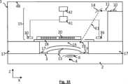
図1Aから図1Eは、本発明による装置1の光音響実施形態と呼ばれる第1の実施形態を示す。装置1は、分析媒体2に対して適用されるように構成される。 Figures 1A to 1E show a first embodiment, called optoacoustic embodiment, of a
装置は、分析媒体2に伝播する励起光11を放射するように構成された励起光源10を備える。光源10は、励起周波数f11でパルス化又は振幅変調される。光波11は、媒体中に存在する分析物4の吸収波長λ4を含む励起スペクトル帯域Δλ11で放射される。装置1の目的の1つは、分析物4の存在を検出し、潜在的にその濃度を推定することである。The apparatus comprises an
励起スペクトル帯域は、好ましくは可視または赤外にあり、例えば、3μmと15μmの波長の間に広がる。好ましくは、励起スペクトル帯域Δλ11は、装置1が単一の分析物に特異的であるために十分に狭い。例えば、発光スペクトル帯域の幅は、1cm-1のオーダである。分析物がグルコースの場合、発光スペクトル帯域はグルコースの吸収波長、例えば1034cm-1を中心とする。励起光源10は、特にパルスレーザ光源であってもよく、例えば波長可変量子カスケードレーザ(QCL)であってもよい。発光スペクトル帯域Δλは赤外に位置する。The excitation spectral band is preferably in the visible or infrared, for example extending between wavelengths of 3 μm and 15 μm. Preferably, the excitation spectral band Δλ11 is narrow enough for the
分析物4は、分析媒体中に存在する分子であってもよい。媒体が生物組織である場合、それは生物組織の体液中に存在するグルコースの問題であり得る。先行技術に関して述べたように、分析物は気体分子であってもよく、媒体は気体である。例えば、汚染物質と考えられる気体分子であってもよい。媒体は液体であってもよく、分析物は液体中に潜在的に存在する分子である。
装置1は、分析媒体2に接触するように分析媒体2に適用されることが意図される接触面3を備える。接触面3は、適用されること意図される媒体2に適合するように設計される。例えば平面である。 The
装置1は、接触面3から延び、中空空洞16を画定する包囲部17を備える。中空空洞16は、媒体2に開口するように接触面3に形成された開口部13を備える。励起光源10は、励起光波11が中空空洞16を通って開口部13を通って媒体2に伝播するように構成される。 The
媒体2中の分析物4の存在の影響下で光音響波6が形成される。光音響波6は、入射光波11によって媒体が周期的に加熱された結果形成される音響波であり、入射光波は励起周波数f11で振幅変調される。光音響波6の一部は、トランスデューサ15によって検出されるように中空空洞16を通って伝播する。Photoacoustic waves 6 are formed under the influence of the presence of the
光音響の実施形態では、トランスデューサ15は音響トランスデューサである。その機能は、光音響波6の振幅及び/又は周波数を測定することである。より正確には、目標とする用途において、トランスデューサ15は、励起光波の励起周波数f11における光音響波6の振幅を推定することを可能にする。In optoacoustic embodiments,
トランスデューサ15は、光音響波6にさらされるとき、振動するように構成された可撓性膜18を備える。膜18は、半径方向平面PXYに平行であることが好ましい。膜の直径またはその最大対角線は、1mmから10mmである。膜の厚さは、横軸Zに平行で、半径方向の面に垂直であり、好ましくは10μmから500μm、好ましくは10μmから100μmである。膜の厚さは、好ましくは、膜の半径(またはその最大の半対角線)の1/10から1/200の間である。
励起光源10は、励起光11が中空空洞16を介して媒体2に伝播するように構成されている。図1Aに示す例では、励起光波11は、膜18を貫通して形成された二次開口部19を通って伝播する。 The
膜に形成された二次開口部19は、膜18の両側の圧力を低周波数で平衡状態にすることも可能である。これにより、膜18の両側の圧力の低周波変動の影響下での膜18の潜在的な変形を回避することができる。圧力の低周波変動とは、膜の動作周波数範囲より低い周波数で生じる圧力差を意味する。二次開口部19の直径は、例えば、膜の直径の1/10未満である。例えば、10μmまたは20μmのオーダである。 A
トランスデューサ15は、膜18上に延び、膜と接触し、膜に平行な導波路20を備える。導波路は、入口20iと出口20oとの間に延在する。導波路は、第1の屈折率n1を有する第1の材料21から作られる。The
導波路20は光ファイバであってもよく、この場合、第1の材料は光ファイバのコアの材料である。また、第1の材料21の薄い層、例えばSiON(酸窒化シリコン)の堆積物から形成される導波路の問題であってもよく、これは図1Aから図1Eに示される例に対応する。導波路は、屈折率が第1の材料n1の屈折率n3よりも低い閉じ込め材料23によって囲まれる。導波路20が光ファイバの場合、閉じ込め材料23は光ファイバのクラッドである。
導波路20は、有利には、第1の材料21の薄い層から形成され、閉じ込め材料23は、単に、第1の材料を取り囲む空気であってもよい。導波路の横軸Zに沿った厚さは、10μmまたは5μm未満であることが好ましい。このような導波路を形成するために用いられる製造工程を図6Aから図6Dを参照して説明する。膜上に直接導波路を形成することにより、光ファイバを膜に接合する工程を回避することができる。光ファイバの使用に関する別の利点は、より剛性の低い導波路が得られることである。
選択された構成にかかわらず、閉じ込め材料23の屈折率n3は、第1の材料21の屈折率n1よりも低い。第1の材料21が膜18上に直接堆積される場合、第1の材料21の屈折率n1は、膜18が形成される材料の屈折率よりも高いことが好ましい。Regardless of the configuration chosen, the
導波路20の一例を図1Bに示す。この例では、第1の材料21は、膜18上に堆積される。導波路は、第2の屈折率n2の第2の材料22のセグメントを備え、これらのセグメントは、導波路20に沿って周期的に分布される。第2の屈折率n2は、第1の屈折率n1とは異なる。第1屈折率n1より高くてもよい。第1の屈折率と第2の屈折率との間の相対的な変化は、0.01%(10-4)から0.1%(10-3)まで変化し得る。An example of
導波路によって規定される軸に沿って、屈折率がn1とn2との間で周期的に変調され、反射スペクトル帯域Δλ20内にブラッグミラーを形成する。ブラッグミラーの構造は、当業者には公知である。屈折率が周期的に変化し、光が伝播する軸に沿って、2つの異なる屈折率のセグメントが交互に形成される構造であり、それぞれのセグメントの光学的厚さは、λB/4niであり、ここで、λBは、反射スペクトル帯域Δλ20の中心波長であり、niは、問題の材料の屈折率(ni=n1またはni=n2)である。屈折率コントラストが低いほど、周期の数が多くなる。Along the axis defined by the waveguide, the refractive index is periodically modulated betweenn1 andn2 , forming a Bragg mirror within the reflected spectral bandΔλ20 . The structure of Bragg mirrors is well known to those skilled in the art. A structure in which the refractive index varies periodically, and two segments of different refractive indices are alternately formed along the axis of light propagation, and the optical thickness of each segment is λB /4ni where λB is the center wavelength of the reflected spectral band Δλ20 and ni is the refractive index of the material in question (ni =n1 or ni =n2 ). The lower the index contrast, the higher the number of periods.
反射スペクトル帯域Δλ20は、共振波長λrを中心とする。後者は以下のようなものである。
neffは回折格子の有効な指標であり、
導波路20は、セグメント21とセグメント22とが交互に形成されたブラッグミラーが欠陥を含むようなものである。欠陥とは、屈折率変調の周期性における局所的な破断を意味する。この欠陥は、例えば、所定の材料、例えば、第1の材料21で作られ、一期間の長さΛ又は複数の連続した期間の長さを延長した連続した空間25に対応する。欠陥と同じレベルでは、導波路は単一の材料を含み、導波路20の軸に沿って距離dが延びる。距離dは、
d>kλB/neffである場合、また、反射スペクトル帯域Δλ20には、ブラッグ波長λBと異なる他の共振波長λrが現れることがある。この場合、共振ピークが最も狭い共振波長を保持することが好ましい。If d>kλB /neff , another resonant wavelength λr different from the Bragg wavelength λB may also appear in the reflected spectral band Δλ20 . In this case, it is preferable to maintain the resonance wavelength with the narrowest resonance peak.
これにより、欠陥は、導波路20において、第1ブラッグミラー241と第2ブラッグミラー242とを分離することができる。第1のブラッグミラー241、第2のブラッグミラー242、およびブラッグミラー間の空間25によって形成されるアセンブリが、共振空洞26を形成する。This allows the defect to separate the first Bragg mirror 24 -1 and the second Bragg mirror 24- 2 in the
次に、導波路20は、
共振波長λrではなくブラッグミラー241、242の反射スペクトル帯域Δλ20の光を反射し、
共振空洞26の共振波長λrで光を透過させる、ように構成される。The
reflect light in the reflection spectral band Δλ20 of the Bragg mirrors 241 , 242 rather than at the resonant wavelength λr ;
It is configured to transmit light at the resonant wavelength λr of
トランスデューサ15は、導波路20の入口20iに向かって補助光波32を放射するように配置された補助光源30、特にレーザダイオードも備える。補助光波32は、発光波長λ32を中心とする発光スペクトル帯域Δλ32で放射される。発光スペクトル帯域Δλ32は、反射スペクトル帯域Δλ20に含まれることが好ましい。The
好ましくは、発光スペクトル帯域Δλ32の幅は、反射スペクトル帯域Δλ20の幅よりも狭い。例えば、発光スペクトル帯域Δλ32の幅は、1nmであってもよく、500PMや100PMよりも小さくてもよい。発光スペクトル帯域Δλ32の幅は、発光スペクトル帯域の半値全幅を意味する。Preferably, the width of the emission spectral band Δλ32 is narrower than the width of the reflection spectral band Δλ20 . For example, the width of the emission spectral band Δλ32 may be 1 nm and may be less than 500 PM or 100 PM. The width of the emission spectral band Δλ32 means the full width at half maximum of the emission spectral band.
補助光源30は、連続波レーザであることが好ましい。これは、例えば、1mWの出力を有し、1.55μmの波長で発光し、1pmのオーダのスペクトル幅を有するDFBレーザダイオード(DFBは分布帰還(distributed feedback)の頭字語である)であってもよい。このタイプのレーザダイオードは、電気通信の分野で一般的に使用されている。 The auxiliary
トランスデューサ15は、光検出器36、好ましくは高速光検出器、およびここではフォトダイオードを備える。光検出器は、反射スペクトル帯域Δλ20を含む検出スペクトル帯域Δλ36を有する。The
トランスデューサ15は、共振空洞26の共振波長λrの時間依存変調λr(t)に従うように構成されたサーボ回路41を備える。このような回路を、図4Aおよび図4Bを参照して以下に説明する。サーボ回路41は、補助光源30が発する補助光波32の発光波長λ32を共振空洞26の共振波長λrに対応させるなど、補助光源をサーボ制御できる。The
装置は、サーボ回路41によって決定された時間依存変調λr(t)の周波数


装置は、後部容積を規定するカバー48を備え、後部容積は、膜18とカバー48との間に延びる容積に対応する。一般に、導波路20は、第1の反射器241および第2の反射器242から形成された共振空洞26を備え、当該反射器は、導波路20を微細構造化することによって得られる。この説明で与えられる例では、第1の反射器241および第2の反射器242はブラッグミラーであるが、他のタイプの微細構造も考えられる。The device comprises a
本発明の1つの重要な側面は、以下に説明するように、以下の事実に関係する。
補助光源30が活性化され、その発光波長λ32が導波路20の共振波長λr(またはより正確には共振空洞26の共振波長)に対応しない光波32を放射すると、導波路20は反射波32’を反射する。しかし
補助光源30が活性化され、その発光波長λ32が共振空洞26の共振波長λrに対応する光波32を放射すると、導波路20は透過波34を光検出器36に伝達する。発光波長λ32が共振波長λrに近づくほど、透過波34の強度は高くなる。One important aspect of the invention, as explained below, relates to the following facts.
When auxiliary
本発明は、音響周波数faの音波6にさらされると、膜18が光音響波6の周波数faで振動の振幅Aaで振動することに基づいている。この結果、導波路20は周期的に変形し、その変形の影響下で共振波長λrは周期的な時間依存変調λr(t)を示す。共振波長の時間依存変調の振幅


図1Cは、図1Aを参照して説明した、放射平面PXY内の特定の要素の図を示す。この例では、膜18は、半径の100分の1の厚さである薄い円盤の形態をとる。FIG. 1C shows a view of certain elements in the radiation planePXY , described with reference to FIG. 1A. In this example, the
図1Dは、分析媒体2に対する膜18および導波路20の位置を示す三次元図である。 FIG. 1D is a three-dimensional view showing the position of
図1Eは、励起光源10が反射器14と関連する装置の例を示す。励起光11は、放射面PXYに平行に放射され、反射器14によって開口部13に向かって反射されて媒体2に向かって伝播する。補助光源30および光検出器36は、導波路20に対して位置合わせされる。あるいは、補助光源30および/または光検出器36は、フォトニック結晶によって導波路20に結合されてもよい。FIG. 1E shows an example of an apparatus in which an
一変形例によれば、トランスデューサ15の膜18は、音響チャネルによって空洞に接続され、空洞16は、光音響波6の一部を膜18に伝達する。 According to one variant, the
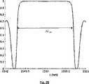
図2Aは、導波路20が微細構造光ファイバであり、その内部にブラッグ回折格子が形成される実施形態を示す。光ファイバにおけるこの種の微細構造は、通常、ファイバブラッグ回折格子(FBG(fiber Bragg Grating))と呼ばれる。光ファイバは、コアを形成する第1の材料21と、クラッドを形成する閉じ込め材料23とを備える。光ファイバのコアには、第1の材料と屈折率が異なる第2の材料22の介在物または空洞が形成されている。図2Bは、このように微細化された光ファイバの反射スペクトルを示す。反射スペクトルは、波長(x軸-単位nm)の関数として照明強度(y軸)によって正規化された反射強度に対応する。反射スペクトル帯域Δλ20で反射が最大となる。このような導波路は、光波32が照射されると、反射スペクトル帯域Δλ20では、全反射スペクトル帯域Δλ20で光波32’を反射する。FIG. 2A shows an embodiment in which waveguide 20 is a microstructured optical fiber with a Bragg grating formed therein. This kind of microstructure in an optical fiber is usually called a fiber Bragg grating (FBG). The optical fiber comprises a
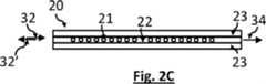
図2Cは、同様の光ファイバを示しており、図1Bを参照して説明したように、二つのブラッグミラー241及び242は、第1の材料21が充填された空間25によって分離されている。空間25の長さが、反射スペクトル帯域に含まれる共振波長の
FIG. 2C shows a similar optical fiber, with two Bragg mirrors 241 and 242 separated by a
図2Dは、このように微細化された光ファイバの反射スペクトルを示す。共振波長λrを除いて、反射スペクトル帯域Δλ20で反射が最大となる。このような導波路は、補助光源30から放射された光波32によって反射スペクトル帯域Δλ20で照明されると、波長λ32が共振波長と異なる場合には光波32’を反射し、波長λ32が共振ピークに位置する場合には透過光波と呼ばれる光波34を透過する。FIG. 2D shows the reflection spectrum of such miniaturized optical fibers. Except for the resonant wavelength λr , the reflection spectral band Δλ20 has a maximum reflection. Such a waveguide, when illuminated in the reflected spectral band Δλ20 by a
図2Cおよび2Dは、Matlab(登録商標、Mathworks)で書かれたモデルを用いて得られたものであり、このモデルでは、構造は3mmの長さLに沿って延びると考えられ、第1および第2の材料間の屈折率コントラストは10-3であると考えられ、それぞれのブラッグミラーの周期は約0.5μmであると考えられた。従って、それぞれのブラッグミラーは、3000に等しい数の周期を有する。Figures 2C and 2D were obtained using a model written in Matlab (Mathworks), in which the structure is assumed to extend along a length L of 3 mm, the first and The index contrast between the second materials was believed to be 10−3 and the period of each Bragg mirror was believed to be approximately 0.5 μm. Therefore, each Bragg mirror has a number of periods equal to 3000.
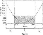
図3Aから図3Cは、図1Bまたは図2Cに示すような導波路20の変形から生じる共振波長λrの変化を示す。図3Aおよび図3Bは、それぞれ、変形されていない導波路および変形された導波路20を示す。変形の影響下で、屈折率変調の空間周期はΛからΛ’=Λ+dΛに変化する。式(1)を適用すると、ブラッグ波長λBにおけるシフトdλBが生じ、この波長は反射スペクトル帯域Δλを拡張する。λBのシフトは、以下のようになる。
εは、μεで表した変形に相当し、10-4%に相当する。変形εは長さの正規化された変動で、次のようになる。
ε corresponds to the deformation expressed in με and corresponds to 10−4 %. The deformation ε is the normalized variation in length, which is:
式(3)は、膜18がSiO2から作られ、第1の材料と第2の材料との間の指数ジャンプが10-3である場合を考慮して得られたものである。これは、図3Bに示すように、それぞれのブラッグミラーの均一な変形に基づいている。式(3)によれば、1マイクロ歪みの変形に対して、ブラッグ波長λBにおけるシフトdλBは1.2pmである。Equation (3) was obtained considering the case where
図3Cでは、導波路20の不均一な変形が示されており、ブラッグミラーのあるセグメントは他のセグメントよりも変形が少ない。 In FIG. 3C, non-uniform deformation of
図3Dは、図3Cを参照して説明したような構成におけるブラッグミラーの反射スペクトルの変化を示すモデルである。曲線a、bおよびcは、それぞれ、変形がないこと、0から10マイクロ歪みの変形、および4から6マイクロ歪みの間の変形に対応する。スペクトルシフトは小さく、10pmより小さい。曲線bおよびcは、導波路の同じ平均変形に対応し、5マイクロ歪みに等しい。これらの2つの構成間の共振波長のシフトは、導波路の軸に沿った歪みの変動に起因し、それぞれ0~10マイクロ歪みおよび4~6マイクロ歪みの範囲である。変形が均一であればあるほど、変形の影響下での共振波長のスペクトルシフトは大きくなる。 FIG. 3D is a model showing the change in reflection spectrum of a Bragg mirror in a configuration such as that described with reference to FIG. 3C. Curves a, b and c correspond to no deformation, deformation from 0 to 10 microstrains, and deformation between 4 to 6 microstrains, respectively. The spectral shift is small, less than 10 pm. Curves b and c correspond to the same average deformation of the waveguide, equal to 5 microstrain. The resonant wavelength shift between these two configurations is due to strain variations along the waveguide axis, ranging from 0-10 microstrain and 4-6 microstrain, respectively. The more uniform the deformation, the greater the spectral shift of the resonant wavelength under the influence of the deformation.
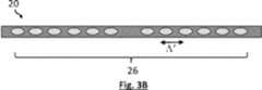
好ましくは、導波路20は、最も大きな変形を受ける膜18の部分の上に延在する。膜18は、振動の振幅が最大となる1つ以上の振動波腹を示す。それぞれの波腹は、モデリングおよび/または実験によって決定することができる。好ましくは、導波路20は、膜の振動の少なくとも1つの波腹上に延在する。これにより、導波路20の変形が最大化され、変形によるスペクトルシフトがさらに増大する。これにより、より良好な感度が得られる。 Preferably,
本発明者らは、図1A及び図1Dに概略的に示すような膜18の変形をモデル化した。モデル化された膜は、半径1mm、厚さ10μmのSiO2から作られ、1Paの圧力にさらされた。膜の直径の1つに沿った変形を図3Eに示す。x軸は膜の中心からの距離(mm)に対応し、y軸はマイクロ歪みの変形に対応する。共振空洞26は、好ましくは、変形の最大振幅を有するレベル、すなわち膜18の中心に設置される。図3Eに示すシミュレーションは、この膜では、1Paの圧力を加えると、いくつかの10-2マイクロ歪みの変形が誘発されることを示している。The inventors have modeled the deformation of
図3Eでは、膜の変形は中央部2cでは負、周辺部2pでは正である。共振空洞26は、有利には、膜2のセグメント上に設置され、膜の振動の影響下で、それが圧縮の問題であるか拡張の問題であるかにかかわらず、変形が同じ符号である。In FIG. 3E the deformation of the membrane is negative in the
図3Fは、共振空洞26が膜2の中央部2cに位置する導波路であって、膜の中心の両側に中心から±0.5mmの距離だけ延びる導波路20を概略的に示す。膜の振動の影響下で、変形は図3Eに示すように交互に負(ε<0)になり、その後正になる。変形が負の場合、光空洞は圧縮され、第2の材料22のセグメントは互いに接近する。変形が正の場合、光空洞は拡大し、第2の材料22のセグメントは互いに離れて移動する。FIG. 3F schematically shows a
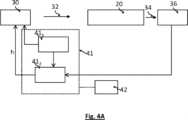
図4Aおよび図4Bは、サーボ回路41の動作を概略的に示し、その機能は、ガイド20に形成された共振空洞26の共振波長λrに波長λ32をサーボ制御することである。サーボ回路41は、波長λ32を共振波長λrに固定する。固定は、通常、トップ・オブ・フリンジ・ロックと呼ばれるタイプである。これは、例えば、Chow J.H. ”Phase-sensitive interrogation of fiber Bragg grating resonators for sensing applications”, J. Light. Technol., vol.23, No.5, pp.1881-1889, May 2005またはBlack E.” An introduction to Pound-Drever-Hall laser frequency stabilization”, Am.J.Phy.69(1), January 2001に記載されている回路のような、ポンド・ドレバ・ホールサーボ技術を使用する回路の問題である。4A and 4B schematically illustrate the operation of
サーボ回路41は、補助光源30によって放射される補助光波32の波長λ32を、10kHzから数百MHzの変調周波数で変調する変調器411を備える。発光波長λ32の変調周波数は、装置によって対処される最大音響周波数よりもはるかに高い。これは、例えば、装置によって対処される最大音響周波数の10倍よりも高くすることができる。導波路20から出て光検出器36で検出された光波34の強度は、サーボ回路41に伝達され、サーボ回路は、光検出器36で検出された強度の変化を波長変調の関数として表す関数hを測定する。The
関数hの符号に応じて、誤差信号が光源に送られ、発光波長λ32が増減する。例えば、波長が増加するにつれて検出される強度の変化が負である場合、発光波長は徐々に減少する。波長の増加につれて検出される強度の変化が正である場合、発光波長は増加する。検出される変調による強度変化が0に近い場合、発光波長は導波路の共振波長に対応する。サーボ回路41は、以下の事実を用いる。
λ32<λrの場合、波長λ32が増加すると透過波34の強度が増加する。逆に、波長λ32の減少は、透過波34の強度の減少をもたらす。
λ32>λrの場合、波長λ32が増加すると、透過波34の強度が減少する。逆に、波長λ32の減少は、透過波34の強度の増加をもたらす。Depending on the sign of the function h, an error signal is sent to the light source to increase or decrease the emission wavelength λ32 . For example, if the change in intensity detected with increasing wavelength is negative, the emission wavelength will gradually decrease. If the change in intensity detected with increasing wavelength is positive, the emission wavelength increases. If the intensity change due to the detected modulation is close to zero, the emission wavelength corresponds to the resonant wavelength of the waveguide. The
If λ32 <λr , the intensity of transmitted
If λ32 >λr , the intensity of transmitted
したがって、補助光波32の波長λ32に小さな変調を適用し、透過光波34の強度に対する変調の効果を観察することによって、補助光源30をサーボ制御して、補助光波32の波長λ32が導波路20の共振波長λrを追跡するようにすることができる。Therefore, by applying a small modulation to the wavelength λ32 of the
トップ・オブ・フリンジ・ロックによって共振波長を追跡することによって、共振波長を、音響周波数が10kHzより高い場合には10-6pmのオーダ、または音響周波数が1kHzより低い場合には10-3pmのオーダの波長感度で追跡することができる。SiO2膜に適用される式(3)を考慮すると、このような感度によって、数ピコ歪み程度、あるいは数mPaに相当する膜の変形を推定することができると推定される。したがって、共振空洞26のスペクトルシフトが小さく、このスペクトルシフトがおそらく数pmのオーダであることを考えると、ポンド・ドレバ・ホール法が適切である。Tracking the resonant wavelength by top-of-fringe locking allows the resonant wavelength to be on the order of10-6 pm for acoustic frequencies above 10 kHz, or10-3 pm for acoustic frequencies below 1 kHz. can be tracked with a wavelength sensitivity of the order of . Considering Eq. (3), which applies to SiO2 films, it is estimated that such sensitivity allows estimation of film deformations on the order of a few pico-strains, or equivalent to a few mPa. Therefore, given that the
また、トップ・オブ・フリンジ・ロックによって共振波長を追跡することにより、温度や湿度などの環境パラメータの変動の影響下で、空洞26の共振波長の変動に対して追跡を鈍感にすることができる。 Tracking the resonant wavelength with a top-of-fringe lock also makes the tracking insensitive to variations in the resonant wavelength of the
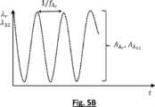
図5Aから図5Cは、光音響波6の影響下で膜18が振動するときの共振波長λrにおける周期的な時間依存変動λr(t)と音響波の振幅との関係を示す。サーボ回路41によって実行されるサーボ制御のため、発光波長λ32(t)における周期的な時間依存変動は、膜振動によって引き起こされる共振波長λr(t)の時間依存変調に対応すると考えられる。図5Aは、導波路20の変形の影響下での透過光波34のスペクトルおよびスペクトルシフトdλrを示す。図5Bは、導波路20の変形から生じる共振波長λrの時間依存変調を示し、変調は周期的であり、音響周波数faに対応する周波数

媒体中の分析物4の濃度の推定は、
分析物の濃度と膜の振動の振幅の間、
または分析物の濃度と共振波長の変調の振幅との間、の関係を確立するために、前もって較正を行うことを必要とすることがある。Estimating the concentration of
Between the concentration of analyte and the amplitude of vibration of the membrane,
Or, it may require prior calibration to establish the relationship between the concentration of the analyte and the amplitude of the modulation of the resonant wavelength.
音響振幅Aaの決定は、必ずしも共振波長の値の決定を必要とせず、変調振幅
図6Aから図6Dは、非光ファイバ導波路20を膜18上に形成することを可能にする主なステップを示す。 6A to 6D show the major steps that allow non-fiber
例えばSiO2(指数1.44)の厚さ4μmの第1の層101、例えばSiON(酸窒化シリコン-指数1.60)の厚さ1μmの第2の層102が堆積された、例えばSi基板である基板100が提供される。図6Aを参照すること。A 4 μm thick
方法は、以下を備える。
フォトリソグラフィを用いて第2の層102をエッチングし、導波路20を形成するステップ。図6Bを参照すること。この例では、SiONが導波路の第1の材料21に対応する。
第1の層101の一部を解放するために、基板100の裏面をエッチングして、当該部分がぶら下がった膜18を形成するステップ。この工程により、中空空洞16を囲む包囲部17を形成することもできる。図6Cを参照すること。
第2の材料22の空洞を形成するために、導波路20をフェムト秒レーザパルスに一点ずつ露光するステップであって、この動作は従来から刻印(inscription)と呼ばれている、露光するステップ。図6Dを参照すること。レーザ照射の影響下で、SiONの指数は局所的に変化する。そのため露出したSiONは、その屈折率n2が露出していないSiONの屈折率と異なる第2の材料22に対応する。具体的には、露光により微小気泡が発生し、屈折率の変化を引き起こす。この結果、光の伝播軸に沿って、導波路20の屈折率が導波路内で変調される。
それぞれのパルスの持続時間は、例えば、800nmの波長で100fsに等しく、それぞれのパルスのエネルギーは30nJである。パルス周波数は、数Hzから200kHzの間で構成することができる。
別の露光技術はUV光刻印であり、これはChow J.H. “Phase-sensitive interrogation of fiber Bragg grating resonators for sensing applications”, J. Light. Technol., vol.23, No.5, pp.1881-1889, May 2005に記載されている。例えば、UV光刻印は、光ファイバを微細構造化することを可能にする。The method comprises:
Etching the
Etching the backside of the
Point-by-point exposure of the
The duration of each pulse is, for example, equal to 100 fs at a wavelength of 800 nm and the energy of each pulse is 30 nJ. The pulse frequency can be configured between a few Hz and 200 kHz.
Another exposure technique is UV light imprinting, which is described in Chow JH “Phase-sensitive interrogation of fiber Bragg grating resonators for sensing applications”, J. Light. Technol., vol.23, No.5, pp.1881-1889. , May 2005. For example, UV light imprinting makes it possible to microstructure optical fibers.
露光によって生じる屈折率の変調は10-3のオーダと比較的小さい。しかし、フェムト秒レーザによる刻印は、ブラッグミラーを例えば1mmオーダの短い長さにわたって製造することを可能にする。このタイプの露光は、高フィネスの共振空洞26を得ることを可能にし、共振ピークの幅は、数十pmよりも小さく、あるいは10pmよりも小さく、場合によっては、5pmよりも小さい。The refractive index modulation caused by exposure is relatively small, on the order of 10−3 . However, femtosecond laser inscription makes it possible to manufacture Bragg mirrors over short lengths, for example of the order of 1 mm. This type of exposure makes it possible to obtain a
それぞれのブラッグミラーが延びる長さを長くすることができる。これは共振ピークの幅を減少させる。 The length over which each Bragg mirror extends can be increased. This reduces the width of the resonance peak.
したがって、光音響の第1の実施形態を採用する場合、図7Aに示される以下のステップを実施することによって、分析媒体中の分析物の存在を検出すること、またはその濃度を推定することさえ可能である。
ステップ110:接触面が媒体に対して保持されるように、装置1を媒体に適用するステップ、
ステップ120:励起光源10を活性化し、励起光源が、分析物の吸収波長λ4に対応する波長を有する励起周波数f11でパルス化または振幅変調された励起光波11を放射する、励起光源を活性化するステップ、
ステップ130:励起光波による媒体の照明の影響下で、中空空洞16を通って伝播する光音響波6の放射を得て、トランスデューサの膜が励起周波数f11で振動し、トランスデューサの導波路20の共振周波数λrが励起周波数f11に等しい変調周波数
ステップ140:サーボ回路41によって、励起周波数f11における導波路20の共振波長λrの時間依存変調、すなわち、導波路の透過ピークに対応する共振波長を決定するステップ、
ステップ150:サーボ回路によって決定された時間依存変調に応じて、励起周波数に依存する周波数、特に励起周波数よりも二倍高い周波数における共振波長の変調の振幅を計算するステップ、
ステップ160:媒体中の分析物の存在を検出し、および/または変調の振幅に依存して分析物濃度を推定するステップ。Therefore, when employing the first embodiment of photoacoustics, detecting the presence of an analyte in the analysis medium, or even estimating its concentration, is performed by performing the following steps shown in FIG. It is possible.
Step 110: applying the
Step 120: Activate the
Step 130: Under the influence of the illumination of the medium by the excitation light wave, obtaining the radiation of the
Step 140: Determining, by the
Step 150: calculating the amplitude of the modulation of the resonant wavelength at a frequency dependent on the excitation frequency, in particular at a frequency two times higher than the excitation frequency, according to the time-dependent modulation determined by the servo circuit;
Step 160: Detecting the presence of the analyte in the medium and/or estimating the analyte concentration depending on the amplitude of the modulation.
分析物の存在は、媒体2を代表し、既知量の分析物を含む較正試料を用いて行われる較正によって検出され得るか、またはその濃度が推定され得る。 The presence of the analyte can be detected or its concentration can be estimated by calibration performed with calibration samples that are representative of
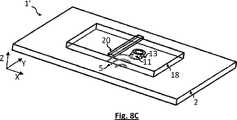
図8Aから8Cは、本発明による装置1’の光熱実施形態と呼ばれる第2の実施形態を示す。装置1’は、分析媒体2に対して適用されるように構成される。 Figures 8A to 8C show a second embodiment, called photothermal embodiment, of the device 1' according to the invention. The
装置1’は、第1の実施形態を参照して説明したような構成要素を備える。一つの相違点は、膜18が、開口部13が形成される支持壁3を形成することである。 The device 1' comprises components as described with reference to the first embodiment. One difference is that the
装置1’は、励起光波11を放射する励起光源10を備える。パルスレーザ源の問題であり、パルス周波数は、例えば、10Hzから500Hzであり、例えば、100Hzに等しい。励起光11は媒体2に伝播する。実施形態によれば、励起光源は、励起光波11が膜18に形成された開口部13を介して媒体2に伝播するように構成されている。 The
媒体中に分析物4が存在する効果の下で、励起波の一部が吸収される。この結果、媒体4の加熱5がされる。分析物が媒体の表面部分に存在する場合、媒体の加熱5は、熱の拡散を介して、接触面を形成する膜18に伝播する。媒体の表面部分とは、接触面と、分析媒体を形成する材料の熱浸透深さの2倍または3倍までの範囲の深さとの間に含まれる部分を意味する。 Part of the excitation wave is absorbed under the effect of the presence of the
膜18は、好ましくは、膜の温度が、おそらくタイムラグの後に、媒体2の温度の変化に従うと考えられるように、熱伝導性を有する。膜はこのような熱伝導率を有するのに十分薄い。 The
この実施形態によれば、トランスデューサ15は熱トランスデューサであり、その機能は、励起光波11による媒体2の周期的な励起の影響下で、膜の温度の周期的な変調を検出することであり、好ましくは定量することである。 According to this embodiment the
トランスデューサ15は、光音響の実施形態に関して説明したように、補助光源30と、導波路20と、光検出器36と、サーボ回路41とを備える。 The
膜18の加熱の影響下で、導波路20の温度が変化する。この結果、共振波長λrの変動が生じ、これは特に、導波路が形成される材料21、22の屈折率の変動に起因する。Under the influence of heating of
温度の影響下における共振波長の変化は、次の式で表すことができる。
補助源32の波長λ32が1.55μmに等しい場合、トランスデューサの感度は、11pm/℃と推定され得る。If the wavelength λ32 of the
光熱の実施形態が使用される場合、図7Bに示される以下のステップを実施することによって、分析された媒体中の分析物の存在を検出すること、またはその濃度を推定することさえ可能である。
ステップ110:接触面(この場合は膜)が媒体に対して保持されるように、装置1を媒体に適用するステップ、
ステップ120:励起光源10を活性化するステップであって、励起光源が分析物の吸収波長λ4に対応する波長を有する励起周波数f11で励起光波11を放射する、励起光源10を活性化するステップ、
ステップ135:励起光波による媒体の照明の影響下で、媒体2の周期的な加熱を得て、生成された熱が熱の拡散を介して膜18に伝播し、トランスデューサの導波路20の共振周波数λrが、励起周波数f11に等しい変調周波数
ステップ140:サーボ回路41によって、励起周波数f11で導波路20の共振波長λrの時間依存変調を決定するステップであって、共振波長は、導波路、変調の透過ピークに対応する時間依存変調を決定するステップ、
ステップ155:サーボ回路によって決定された時間依存性変動に応じて、共振波長の変動の振幅を計算するステップ、
ステップ165:媒体中の分析物の存在を検出し、および/または変動に応じて分析物濃度を推定するステップ。When photothermal embodiments are used, it is possible to detect the presence of an analyte in the analyzed medium, or even estimate its concentration, by performing the following steps shown in FIG. 7B. .
Step 110: applying the
Step 120: Activating the
Step 135: Obtain periodic heating of the
Step 140: Determining, by the
Step 155: Calculating the amplitude of the variation of the resonant wavelength in response to the time dependent variation determined by the servo circuit;
Step 165: Detecting the presence of the analyte in the medium and/or estimating the analyte concentration depending on the variation.
分析物の存在は、媒体2を代表し、既知量の分析物を含む較正試料を用いて行われる較正によって検出され得るか、またはその濃度が推定され得る。 The presence of the analyte can be detected or its concentration can be estimated by calibration performed with calibration samples that are representative of
本発明は、環境分野、産業分野(例えば、食品産業分野)、または生物医学分野における分析物検出用途において、気体、液体または固体試料上に実施される可能性がある。 The invention may be implemented on gas, liquid or solid samples in analyte detection applications in the environmental, industrial (eg food industry), or biomedical fields.
Claims (18)
Translated fromJapanese前記装置は、前記接触面(3)に形成された開口部(13)と、
吸収波長を含む励起スペクトル帯域(Δλ11)において、励起周波数(f11)でパルス化または振幅変調された励起光波(11)を放射するように構成された励起光源(10)であって、前記装置は、前記励起光波(11)が前記開口部(13)を通って前記分析媒体に向かって伝播するように配置される、励起光源(10)と、
前記励起光波(11)の一部を分析物が吸収することによって生じる媒体の周期的な加熱後の媒体の応答を測定することを意図するトランスデューサ(15)と、を備え、
前記トランスデューサ(15)は、
導波路(20)を運ぶ膜(18)と、
第1の反射器(241)と、第2の反射器(242)とを備える前記導波路であって、それぞれの反射器は、反射スペクトル帯域(Δλ20)の光を反射する、前記導波路と、
共振光空洞(26)を形成するように互いに間隔をあけて配置される、第1の反射器及び第2の反射器であって、前記共振光空洞は、反射スペクトル帯域内の共振波長(λr)を規定する、第1の反射器と第2の反射器と、を備え、
前記導波路は、共振波長(λr)で光を透過させ、共振波長ではない反射スペクトル帯域(Δλ20)の光を反射し、
前記トランスデューサは、
反射スペクトル帯域(Δλ20)の補助光波(32)を導波路内に放射するように構成された補助レーザ光源(30)と、
共振波長(λr)で前記導波路を透過する光波(34)を検出するように配置された光検出器(36)と、
前記光検出器(36)に接続され、前記共振光空洞(26)の前記共振波長の周期的な時間依存変調(λr(t))を決定するように構成されたサーボ回路(41)と、を備え、
前記導波路(20)は、前記膜上に直接形成され、
前記膜(18)は、前記媒体の周期的な加熱の影響下で変形するように構成される、装置。A detection device (1, 1′),
Said device comprises an opening (13) formed in said contact surface (3);
an excitation light source (10) configured to emit a pulsed or amplitude modulated excitation light wave (11) at an excitation frequency (f11 ) in an excitation spectral band (Δλ11 ) containing absorption wavelengths, said The device comprises an excitation light source (10) arranged such that said excitation light wave (11) propagates through said opening (13) towards said analysis medium;
a transducer (15) intended to measure the response of the medium after periodic heating of the medium caused by absorption of a portion of said excitation light wave (11) by the analyte;
The transducer (15) is
a membrane (18) carrying a waveguide (20);
said waveguide comprising a first reflector (241 ) and a second reflector (242 ), each reflector reflecting light in a reflected spectral band (Δλ20 ); a waveguide;
A first reflector and a second reflector spaced apart to form a resonant optical cavity (26), said resonant optical cavity having a resonant wavelength (λr ), comprising a first reflector and a second reflector,
the waveguide transmits light at a resonant wavelength (λr ) and reflects light in a reflected spectral band (Δλ20 ) that is not at the resonant wavelength;
The transducer is
an auxiliary laser source (30) configured to emit an auxiliary lightwave (32) in the reflected spectral band (Δλ20 ) into the waveguide;
a photodetector (36) arranged to detect a lightwave (34) transmitted through said waveguide at a resonant wavelength (λr );
a servo circuit (41) connected to the photodetector (36) and configured to determine a periodic, time-dependent modulation (λr (t)) of the resonant wavelength of the resonant optical cavity (26); , and
said waveguide (20) is formed directly on said film,
The apparatus of claim 1, wherein said membrane (18) is configured to deform under the influence of cyclic heating of said medium.
前記共振波長(λr)の時間依存変調の振幅(

推定振幅に応じて、前記媒体(2)中の前記分析物の存在を検出する、請求項1に記載の装置。a processing unit (42) connected to the servo circuit;
The amplitude of the time-dependentmodulation (
2. Apparatus according to claim 1, for detecting the presence of said analyte in said medium (2) as a function of the estimated amplitude.


前記開口部(13)は、前記膜(20)を通って延在し、
前記トランスデューサ(15)は熱トランスデューサであり、前記励起光波(11)による前記媒体の照射の影響下で、前記膜の温度は周期的な時間依存変動を示し、前記共振波長(λr)の周期的な時間依存変調が生じる、請求項1乃至3のいずれか一項に記載の装置(1’)。said membrane (18) of said transducer (15) forms said contact surface (3) of said device, said contact surface intended to be applied to contact said medium (2),
said opening (13) extends through said membrane (20);
Said transducer (15) is a thermal transducer, and under the influence of irradiation of said medium by said excitation light wave (11), the temperature of said film exhibits a periodic time-dependent variation, the period of said resonance wavelength (λr ) 4. A device (1') according to any one of claims 1 to 3, wherein a dynamic time dependent modulation occurs.
前記第2の反射器(242)は、第2のブラッグミラーであり、
前記第1のブラッグミラーと前記第2のブラッグミラーは、欠陥(25)を含む同一のブラッグミラーを形成し、前記第1のブラッグミラーと前記第2のブラッグミラーは、それぞれ前記欠陥の両側に位置する前記ブラッグミラーの部分に対応する、請求項1乃至10のいずれか1項に記載の装置。said first reflector (241 ) is a first Bragg mirror;
said second reflector (242 ) is a second Bragg mirror;
Said first Bragg mirror and said second Bragg mirror form an identical Bragg mirror containing a defect (25), said first Bragg mirror and said second Bragg mirror respectively on either side of said defect. 11. A device according to any one of the preceding claims, corresponding to the part of the Bragg mirror that is located.
前記導波路(20)は、少なくとも一つの波腹と同じ高さにある、請求項1乃至6のいずれか1項に記載の装置。said membrane (18) exhibits at least one vibration antinode when deformed, the amplitude of vibration being maximum at each antinode;
7. Apparatus according to any one of the preceding claims, wherein the waveguide (20) is level with at least one antinode.
a)前記装置の前記接触面(3)が前記媒体に対して保持されるように、前記媒体(2)に対して請求項1乃至13のいずれか1項に記載の装置(1、1’)を適用するステップと、
b)励起光源(10)を活性化するステップであって、前記励起光源は、前記分析物の吸収波長に対応する波長で、励起周波数(f11)でパルス化または振幅変調された励起光波(11)を放射する、励起光源(10)を活性化するステップと、
c)サーボ回路(41)によって、前記励起周波数に対応する変調周波数で、前記トランスデューサ(15)の前記導波路(20)の共振波長(λr)の周期的な変調を決定するステップであって、前記共振周波数は、前記導波路の透過ピークに対応する、周期的な変調を決定するステップと、
d)前記サーボ回路によって決定される周期的な変調に応じて、媒体中の前記分析物の存在を検出するステップと、を備える方法。A method of detecting an analyte (4) in a medium (2), wherein the analyte (4) absorbs light of at least one absorption wavelength, comprising:
a) a device (1, 1') according to any one of claims 1 to 13 to said medium (2) such that said contact surface (3) of said device is held against said medium; ), and
b) activating an excitation light source (10), saidexcitation light source being a pulsed or amplitude modulated excitation light wave ( 11) activating the excitation light source (10), emitting
c) determining by a servo circuit (41) a periodic modulation of the resonant wavelength (λr ) of said waveguide (20) of said transducer (15) at a modulation frequency corresponding to said excitation frequency; determining a periodic modulation, wherein said resonant frequency corresponds to a transmission peak of said waveguide;
d) detecting the presence of said analyte in a medium in response to a periodic modulation determined by said servo circuit.
前記方法は、
ステップb)に続いて、前記励起周波数(f11)で前記媒体(2)を周期的に加熱して光音響波(6)を放射させることにより、前記中空空洞(16)を伝播し、前記トランスデューサ(15)の前記膜(18)が前記励起周波数(f11)で振動する効果の下で、前記トランスデューサの前記導波路(20)の前記共振周波数λrが、前記励起周波数(f11)に等しい変調周波数(

ステップd)において、
前記変調周波数(


)を推定するステップと
推定振幅に応じて前記分析物の存在を検出するステップと、を備える請求項14に記載の方法。The device is a device (1) according to any one of claims 4 to 6,
The method includes:
Following step b), cyclically heating the medium (2) at the excitation frequency (f11 ) to radiate photoacoustic waves (6) to propagate through the hollow cavity (16) and Under the effect that the membrane (18) of the transducer (15) vibrates at the excitation frequency (f11 ), the resonance frequency λr of the waveguide (20) of the transducer is reduced to the excitation frequency (f11 ) Modulation frequency equal to (
in step d)
The modulation frequency (
) and detecting the presence of the analyte as a function of the estimated amplitude.
ステップb)の後、前記励起周波数で前記媒体(2)を周期的に加熱し、前記トランスデューサの前記導波路(20)の前記共振周波数λrが前記励起周波数に対応する変調周波数(

ステップd)において、
前記変調周波数における前記共振波長の周期的な変調の振幅の推定するステップと、
推定振幅に応じて前記分析物の存在を検出するステップと、を備える、請求項14に記載の方法。The apparatus is an apparatus (1') according to claim 7, the method comprising:
After step b), the medium (2) is cyclically heated at the excitation frequency so that the resonance frequencyλr of the waveguide (20) of the transducer is a modulation frequency (
in step d)
estimating the amplitude of the periodic modulation of the resonant wavelength at the modulation frequency;
and detecting the presence of the analyte as a function of the estimated amplitude.
導波路を形成するように、第1の材料の薄い層を膜上に堆積するステップと、
前記導波路の屈折率の周期的な変調を得るように、前記導波路をフェムト秒レーザ光で刻むステップと、を備える製造工程。A manufacturing process for manufacturing a device according to any one of claims 1 to 13, comprising:
depositing a thin layer of a first material on the film to form a waveguide;
and sculpting the waveguide with femtosecond laser light to obtain a periodic modulation of the refractive index of the waveguide.
Applications Claiming Priority (3)
| Application Number | Priority Date | Filing Date | Title |
|---|---|---|---|
| FR1915696 | 2019-12-27 | ||
| FR1915696AFR3105827B1 (en) | 2019-12-27 | 2019-12-27 | Photoacoustic or photothermal detector comprising an optical transducer |
| PCT/EP2020/087866WO2021130364A1 (en) | 2019-12-27 | 2020-12-24 | Photoacoustic or photothermal detector comprising an optical transducer |
Publications (2)
| Publication Number | Publication Date |
|---|---|
| JP2023509000Atrue JP2023509000A (en) | 2023-03-06 |
| JP7607661B2 JP7607661B2 (en) | 2024-12-27 |
Family
ID=70804675
Family Applications (1)
| Application Number | Title | Priority Date | Filing Date |
|---|---|---|---|
| JP2022539400AActiveJP7607661B2 (en) | 2019-12-27 | 2020-12-24 | Photoacoustic or photothermal detector with optical transducer |
Country Status (7)
| Country | Link |
|---|---|
| US (1) | US12228498B2 (en) |
| EP (1) | EP4081782B1 (en) |
| JP (1) | JP7607661B2 (en) |
| KR (1) | KR20220131928A (en) |
| CN (1) | CN114868007B (en) |
| FR (1) | FR3105827B1 (en) |
| WO (1) | WO2021130364A1 (en) |
Families Citing this family (2)
| Publication number | Priority date | Publication date | Assignee | Title |
|---|---|---|---|---|
| FR3105824B1 (en)* | 2019-12-27 | 2022-02-18 | Commissariat Energie Atomique | Optical device for detecting an acoustic wave |
| EP4450953A1 (en)* | 2023-04-20 | 2024-10-23 | Eclypia | Photoacoustic detecting device |
Citations (8)
| Publication number | Priority date | Publication date | Assignee | Title |
|---|---|---|---|---|
| JPH07221368A (en)* | 1994-01-28 | 1995-08-18 | Fujitsu Ltd | Rubidium atomic oscillator |
| JP2005181334A (en)* | 2003-12-22 | 2005-07-07 | Lucent Technol Inc | Optical substance analyzer |
| US20060126435A1 (en)* | 2004-12-15 | 2006-06-15 | Tam Hwa-Yaw | Ultrasound sensor and ultrasound measurement device |
| US20070206193A1 (en)* | 2004-01-13 | 2007-09-06 | Glucon, Inc. | Photoacoustic Sensor |
| JP2011196744A (en)* | 2010-03-18 | 2011-10-06 | National Institute Of Advanced Industrial Science & Technology | Fbg vibration detecting system, and device and vibration detecting method using the system |
| US20120151994A1 (en)* | 2010-12-15 | 2012-06-21 | Texas Instruments Incorporated | Active detection techniques for photoacoustic sensors |
| US20140114187A1 (en)* | 2011-02-04 | 2014-04-24 | Helmholtz Zentrum München Deutsches Forschungszentrum für Gesundheit und Umwelt (GmbH | Ultrasound detector and detecting device for optoacoustic or thermoacoustic imaging |
| WO2019170884A1 (en)* | 2018-03-09 | 2019-09-12 | Technische Universität München | Sensor comprising a waveguide with optical resonator and sensing method |
Family Cites Families (8)
| Publication number | Priority date | Publication date | Assignee | Title |
|---|---|---|---|---|
| US7352468B2 (en)* | 2001-12-12 | 2008-04-01 | Trustees Of Princeton University | Cavity ring-down detection of surface plasmon resonance in an optical fiber resonator |
| US7263871B2 (en)* | 2004-12-08 | 2007-09-04 | Finesse Solutions Llc. | System and method for gas analysis using doubly resonant photoacoustic spectroscopy |
| US20100192669A1 (en)* | 2007-07-06 | 2010-08-05 | Koninklijke Philips Electronics N.V. | Photo acoustic sample detector with light guide |
| US20110072886A1 (en)* | 2009-09-30 | 2011-03-31 | Catherine Genevieve Caneau | Gas Sensor Based On Photoacoustic Detection |
| US8327686B2 (en)* | 2010-03-02 | 2012-12-11 | Li-Cor, Inc. | Method and apparatus for the photo-acoustic identification and quantification of analyte species in a gaseous or liquid medium |
| CN102053105A (en)* | 2010-11-23 | 2011-05-11 | 吉林大学 | Method for detecting thermal effect of interaction of laser and matter by using fiber grating |
| WO2017097824A1 (en) | 2015-12-09 | 2017-06-15 | Diamontech Gmbh | Device and method for analysing a material |
| FR3078155B1 (en)* | 2018-02-19 | 2020-08-14 | Commissariat Energie Atomique | PHOTO-ACOUSTIC SENSOR WITH OPTO-MECHANICAL COUPLING. |
- 2019
- 2019-12-27FRFR1915696Apatent/FR3105827B1/enactiveActive
- 2020
- 2020-12-24CNCN202080090135.5Apatent/CN114868007B/enactiveActive
- 2020-12-24KRKR1020227026137Apatent/KR20220131928A/enactivePending
- 2020-12-24EPEP20838568.2Apatent/EP4081782B1/enactiveActive
- 2020-12-24WOPCT/EP2020/087866patent/WO2021130364A1/ennot_activeCeased
- 2020-12-24USUS17/757,935patent/US12228498B2/enactiveActive
- 2020-12-24JPJP2022539400Apatent/JP7607661B2/enactiveActive
Patent Citations (8)
| Publication number | Priority date | Publication date | Assignee | Title |
|---|---|---|---|---|
| JPH07221368A (en)* | 1994-01-28 | 1995-08-18 | Fujitsu Ltd | Rubidium atomic oscillator |
| JP2005181334A (en)* | 2003-12-22 | 2005-07-07 | Lucent Technol Inc | Optical substance analyzer |
| US20070206193A1 (en)* | 2004-01-13 | 2007-09-06 | Glucon, Inc. | Photoacoustic Sensor |
| US20060126435A1 (en)* | 2004-12-15 | 2006-06-15 | Tam Hwa-Yaw | Ultrasound sensor and ultrasound measurement device |
| JP2011196744A (en)* | 2010-03-18 | 2011-10-06 | National Institute Of Advanced Industrial Science & Technology | Fbg vibration detecting system, and device and vibration detecting method using the system |
| US20120151994A1 (en)* | 2010-12-15 | 2012-06-21 | Texas Instruments Incorporated | Active detection techniques for photoacoustic sensors |
| US20140114187A1 (en)* | 2011-02-04 | 2014-04-24 | Helmholtz Zentrum München Deutsches Forschungszentrum für Gesundheit und Umwelt (GmbH | Ultrasound detector and detecting device for optoacoustic or thermoacoustic imaging |
| WO2019170884A1 (en)* | 2018-03-09 | 2019-09-12 | Technische Universität München | Sensor comprising a waveguide with optical resonator and sensing method |
Also Published As
| Publication number | Publication date |
|---|---|
| EP4081782B1 (en) | 2025-08-27 |
| FR3105827A1 (en) | 2021-07-02 |
| US12228498B2 (en) | 2025-02-18 |
| KR20220131928A (en) | 2022-09-29 |
| JP7607661B2 (en) | 2024-12-27 |
| WO2021130364A1 (en) | 2021-07-01 |
| FR3105827B1 (en) | 2024-07-19 |
| EP4081782A1 (en) | 2022-11-02 |
| US20220364981A1 (en) | 2022-11-17 |
| CN114868007A (en) | 2022-08-05 |
| CN114868007B (en) | 2025-08-26 |
Similar Documents
| Publication | Publication Date | Title |
|---|---|---|
| EP3761853B1 (en) | Sensor comprising a waveguide with optical resonator and sensing method | |
| Broadway et al. | Toward commercial polymer fiber Bragg grating sensors: Review and applications | |
| Zhang et al. | Ultrabroad bandwidth and highly sensitive optical ultrasonic detector for photoacoustic imaging | |
| Cao et al. | Ultrasound sensing with optical microcavities | |
| CN112955075A (en) | Device and method for analyzing substances | |
| CN112345459B (en) | A transceiver integrated fiber optic ultrasonic probe, ultrasonic excitation and detection system | |
| JP7607661B2 (en) | Photoacoustic or photothermal detector with optical transducer | |
| JP7749333B2 (en) | Apparatus for detecting an analyte by photoacoustic detection - Patent Application 20070122997 | |
| Liang et al. | High spatiotemporal resolution optoacoustic sensing with photothermally induced acoustic vibrations in optical fibres | |
| US12379234B2 (en) | Optical device for detecting an acoustic wave | |
| CN115485549A (en) | Optical microresonator array apparatus for ultrasonic sensing | |
| Fan et al. | Fiber-optic ultrasound transmitter based on multi-mode interference in curved adhesive waveguide | |
| JP2022101522A (en) | Photoacoustic detection device comprising protective membrane | |
| KR20110120485A (en) | Fiber Bragg Grating Sensor and Method of Manufacturing the Same | |
| Bao et al. | Photoacoustic Imaging Sensors Based on Integrated Photonics: Challenges and Trends | |
| JP4773390B2 (en) | Component concentration measuring device | |
| WO2020137515A1 (en) | Component concentration measuring device | |
| KR20240128055A (en) | An optoacoustic detection device comprising a membrane forming a contact surface | |
| Govindan et al. | Polymer Bragg waveguide ultrasound detectors | |
| Avino et al. | Fiber-optic resonators for strain-acoustic sensing and chemical spectroscopy | |
| Zhu et al. | An Integrated Broadband Ultrasound Sensor based on a Photonic Crystal Slab | |
| Han | Manufacturing and aerostatic tunability of opto-mechano-fluidic resonator and its application in viscosity sensing | |
| MacLean et al. | The Fiber Fabry-Pérot Cavity as a Multipurpose Sensor | |
| WO2020137537A1 (en) | Component concentration measuring device |
Legal Events
| Date | Code | Title | Description |
|---|---|---|---|
| A621 | Written request for application examination | Free format text:JAPANESE INTERMEDIATE CODE: A621 Effective date:20231101 | |
| A977 | Report on retrieval | Free format text:JAPANESE INTERMEDIATE CODE: A971007 Effective date:20240729 | |
| A131 | Notification of reasons for refusal | Free format text:JAPANESE INTERMEDIATE CODE: A131 Effective date:20240806 | |
| A521 | Request for written amendment filed | Free format text:JAPANESE INTERMEDIATE CODE: A523 Effective date:20241101 | |
| TRDD | Decision of grant or rejection written | ||
| A01 | Written decision to grant a patent or to grant a registration (utility model) | Free format text:JAPANESE INTERMEDIATE CODE: A01 Effective date:20241119 | |
| A61 | First payment of annual fees (during grant procedure) | Free format text:JAPANESE INTERMEDIATE CODE: A61 Effective date:20241217 | |
| R150 | Certificate of patent or registration of utility model | Ref document number:7607661 Country of ref document:JP Free format text:JAPANESE INTERMEDIATE CODE: R150 |