JP2023508119A - System and method for GNSS ambiguity determination - Google Patents
System and method for GNSS ambiguity determinationDownload PDFInfo
- Publication number
- JP2023508119A JP2023508119AJP2022563555AJP2022563555AJP2023508119AJP 2023508119 AJP2023508119 AJP 2023508119AJP 2022563555 AJP2022563555 AJP 2022563555AJP 2022563555 AJP2022563555 AJP 2022563555AJP 2023508119 AJP2023508119 AJP 2023508119A
- Authority
- JP
- Japan
- Prior art keywords
- measurements
- receiver
- state
- satellite
- measurement
- Prior art date
- Legal status (The legal status is an assumption and is not a legal conclusion. Google has not performed a legal analysis and makes no representation as to the accuracy of the status listed.)
- Pending
Links
Images


Classifications
- G—PHYSICS
- G01—MEASURING; TESTING
- G01S—RADIO DIRECTION-FINDING; RADIO NAVIGATION; DETERMINING DISTANCE OR VELOCITY BY USE OF RADIO WAVES; LOCATING OR PRESENCE-DETECTING BY USE OF THE REFLECTION OR RERADIATION OF RADIO WAVES; ANALOGOUS ARRANGEMENTS USING OTHER WAVES
- G01S19/00—Satellite radio beacon positioning systems; Determining position, velocity or attitude using signals transmitted by such systems
- G01S19/38—Determining a navigation solution using signals transmitted by a satellite radio beacon positioning system
- G01S19/39—Determining a navigation solution using signals transmitted by a satellite radio beacon positioning system the satellite radio beacon positioning system transmitting time-stamped messages, e.g. GPS [Global Positioning System], GLONASS [Global Orbiting Navigation Satellite System] or GALILEO
- G01S19/42—Determining position
- G01S19/43—Determining position using carrier phase measurements, e.g. kinematic positioning; using long or short baseline interferometry
- G01S19/44—Carrier phase ambiguity resolution; Floating ambiguity; LAMBDA [Least-squares AMBiguity Decorrelation Adjustment] method
- G—PHYSICS
- G01—MEASURING; TESTING
- G01S—RADIO DIRECTION-FINDING; RADIO NAVIGATION; DETERMINING DISTANCE OR VELOCITY BY USE OF RADIO WAVES; LOCATING OR PRESENCE-DETECTING BY USE OF THE REFLECTION OR RERADIATION OF RADIO WAVES; ANALOGOUS ARRANGEMENTS USING OTHER WAVES
- G01S19/00—Satellite radio beacon positioning systems; Determining position, velocity or attitude using signals transmitted by such systems
- G01S19/38—Determining a navigation solution using signals transmitted by a satellite radio beacon positioning system
- G01S19/39—Determining a navigation solution using signals transmitted by a satellite radio beacon positioning system the satellite radio beacon positioning system transmitting time-stamped messages, e.g. GPS [Global Positioning System], GLONASS [Global Orbiting Navigation Satellite System] or GALILEO
- G01S19/393—Trajectory determination or predictive tracking, e.g. Kalman filtering
Landscapes
- Engineering & Computer Science (AREA)
- Radar, Positioning & Navigation (AREA)
- Remote Sensing (AREA)
- Computer Networks & Wireless Communication (AREA)
- Physics & Mathematics (AREA)
- General Physics & Mathematics (AREA)
- Position Fixing By Use Of Radio Waves (AREA)
Abstract
Translated fromJapaneseDescription
Translated fromJapanese本発明は、概して、全地球測位システム(global positioning system:GPS)または準天頂衛星システム(Quasi-Zenith Satellite System:QZSS)などの測位システムに関し、より具体的には、このような測位システムにおいて受信機によって搬送波位相測定における整数アンビギュイティを決定することに関する。 The present invention relates generally to positioning systems, such as the global positioning system (GPS) or the Quasi-Zenith Satellite System (QZSS), and more particularly to positioning systems such as receiving Determining integer ambiguities in carrier phase measurements by machine.
全地球航法衛星システム(Global Navigation Satellite System:GNSS)は、地球に対するモバイル受信機の地理的位置を求めるのに用いることができる衛星のシステムである。GNSSは、GPS、Galileo、Glonass、QZSS、およびBeiDouを含む。モバイル受信機の地理的位置のさらに迅速かつ正確な計算を達成するために、GNSS衛星からGNSS信号データを受信し、これらのGNSSデータを処理し、GNSSデータからGNSS補正を計算し、これらの補正をモバイル受信機に提供するように構成される、さまざまな全地球航法衛星(GNS)補正システムが知られている。 The Global Navigation Satellite System (GNSS) is a system of satellites that can be used to determine the geographical position of a mobile receiver relative to the earth. GNSS includes GPS, Galileo, Glonass, QZSS, and BeiDou. receiving GNSS signal data from GNSS satellites, processing these GNSS data, calculating GNSS corrections from the GNSS data, and calculating GNSS corrections from these GNSS data in order to achieve an even faster and more accurate calculation of the geographical position of the mobile receiver; Various global navigation satellite (GNS) correction systems are known that are configured to provide .
さまざまな位置推定方法が知られており、これらの方法では、位置計算は、地球ベースのGNSS受信機によるいわゆる擬似距離(pseudo range)および搬送波位相観測値の反復測定に基づいている。「擬似距離」または「コード」観測値は、GNSS衛星信号の送信時刻とこの衛星信号のローカル受信時刻との差を表しており、したがって、衛星の無線信号によってカバーされる幾何学的距離を含む。加えて、受信したGNSS衛星信号の搬送波と、受信機内で生成されるこのような信号のコピーとの間のアライメントの測定により、衛星と受信機との間の見かけの距離を求めるための別の情報源が提供される。この対応する観測値は「搬送波位相」と呼ばれ、送信側衛星と受信機との相対運動に起因するドップラー周波数の積分値を表している。 Various position estimation methods are known, in which the position calculation is based on repeated measurements of so-called pseudo range and carrier phase observations by earth-based GNSS receivers. A "pseudorange" or "code" observation represents the difference between the time of transmission of a GNSS satellite signal and the time of local reception of this satellite signal, and thus includes the geometric range covered by the satellite's radio signal. . In addition, measurement of the alignment between the carrier of the received GNSS satellite signal and the copy of such signal generated within the receiver provides another method for determining the apparent distance between the satellite and the receiver. Sources are provided. This corresponding observation is called "carrier phase" and represents the integral of the Doppler frequency due to the relative motion between the transmitting satellite and the receiver.
すべての擬似距離観測値は不可避の誤差寄与を含み、この誤差寄与の中には、受信機と送信機とのクロック誤差、および大気の非ゼロ屈折率によって生じる追加遅延、機器遅延、マルチパス効果、および検出器ノイズがある。すべての搬送波位相観測値は、この信号アライメントへのロックインが得られるまでに経過した未知の整数の信号サイクル、すなわち整数の波長をさらに含む。この数は「搬送波位相アンビギュイティ」と呼ばれる。通常、観測値は、測定される、すなわち、連続した離散時刻において受信機によってサンプリングされる。観測値が測定される時刻のインデックスは「エポック」と呼ばれる。公知の位置判定方法は、一般に、連続したエポックにおいてサンプリングされた観測値の測定に基づく、距離および誤差成分についての動的な数値推定および補正方式を伴う。 All pseudorange observations contain unavoidable error contributions, among which are receiver and transmitter clock errors, and additional delays caused by the non-zero refractive index of the atmosphere, instrument delays, multipath effects , and detector noise. All carrier phase observations further include an unknown integer number of signal cycles, or integer wavelengths, that have elapsed before lock-in to this signal alignment is obtained. This number is called the "carrier phase ambiguity". Observations are typically measured, ie, sampled by the receiver at successive discrete times. The time index at which an observation is measured is called the "epoch". Known position determination methods generally involve dynamic numerical estimation and correction schemes for range and error components based on measurements of sampled observations at consecutive epochs.
GNSS信号が連続して追跡され、ロックの喪失が発生していない場合、追跡段階の開始時に決定された整数アンビギュイティは、全GNSS測位期間にわたって維持することができる。しかしながら、GNSS衛星信号は、(たとえば、「アーバンキャニオン」環境における建物に起因して)時折遮られることがあり、または、(たとえば、受信機が橋の下もしくはトンネルを通るときに)瞬間的に遮断されることがある。一般に、このような場合には、整数アンビギュイティ値は失われ、再度求めなければならない。このプロセスは数秒から数分かかる場合がある。実際、擬似距離または搬送波位相のいずれかの1つ以上の測定値に大きなマルチパス誤差またはモデル化されていない系統的バイアスが存在していると、現在の商用測位システムを用いてアンビギュイティを決定することが困難になる場合がある。受信機離隔(すなわち、基準受信機と、位置を特定中のモバイル受信機との間の距離)が大きくなるにつれて、距離依存バイアス(たとえば、軌道誤差ならびに電離層および対流圏の影響)が増大し、その結果、信頼性のあるアンビギュイティ決定(または再初期化)がより一層困難になる。さらに、信号上の受信機の連続的な位相ロックの不連続性(サイクルスリップと呼ばれる)に起因して、ロックの喪失も発生する場合がある。たとえば、サイクルスリップは、電力損失、受信機ソフトウェアの故障、または衛星発振器の不具合によって生じる場合がある。加えて、サイクルスリップは、電離層の状態が変化することによって生じる場合がある。 If the GNSS signal is continuously tracked and no loss of lock has occurred, the integer ambiguity determined at the beginning of the tracking phase can be maintained for the entire GNSS fix period. However, GNSS satellite signals can be occasionally blocked (e.g., due to buildings in an "urban canyon" environment) or momentarily (e.g., when the receiver is under a bridge or through a tunnel). It may be blocked. Generally, in such cases the integer ambiguity values are lost and must be re-determined. This process may take seconds to minutes. In fact, the presence of large multipath errors or unmodeled systematic biases in one or more measurements of either pseudorange or carrier phase can lead to ambiguities using current commercial positioning systems. Decisions can be difficult. As the receiver separation (i.e., the distance between the reference receiver and the mobile receiver being located) increases, the range-dependent biases (e.g., orbital errors and ionospheric and tropospheric effects) increase and As a result, reliable ambiguity determination (or reinitialization) becomes much more difficult. In addition, loss of lock may also occur due to discontinuities in the continuous phase lock of the receiver on the signal (called cycle slips). For example, cycle slips may be caused by power loss, receiver software failure, or satellite oscillator failure. Additionally, cycle slips may be caused by changes in ionospheric conditions.
GNSSの改良は、全地球測位システムまたはその他の全地球航法衛星システム(一般にナビゲーションに使用される衛星のネットワーク)によって提供される測位情報の精度を高めるために使用される技術を指す。たとえば、衛星間の差分、受信機間の差分、エポック間の差分、およびその組合せに基づく差分技術を使用する方法もある。衛星と受信機との間の一重差および二重差は、明示的または近似的に誤差源を減らす。しかしながら、GNSSの場合、各衛星はいくつかの周波数帯で搬送波測定値およびコード測定値を送信することができ、これは、差分測定に使用可能な異なる衛星と組合せると、リアルタイムのGNSS測位では禁止され得る測定次元のサイズを暗示する。 GNSS enhancements refer to techniques used to increase the accuracy of positioning information provided by the Global Positioning System or other global navigation satellite systems (networks of satellites commonly used for navigation). For example, some methods use differencing techniques based on inter-satellite differencing, inter-receiver differencing, inter-epoch differencing, and combinations thereof. Single and double differences between the satellite and the receiver either explicitly or approximately reduce error sources. However, for GNSS, each satellite can transmit carrier and code measurements on several frequency bands, which, when combined with the different satellites available for differential measurements, means that real-time GNSS positioning has Implies the size of the measurement dimension that may be prohibited.
したがって、GNSS測位の品質を維持しつつ測定次元を減らす方法が必要とされている。 Therefore, there is a need for a method to reduce the measurement dimensionality while maintaining the quality of GNSS positioning.
いくつかの実施形態の目的は、全地球航法衛星システム(GNSS)における受信機の位置を追跡する方法およびシステムを提供することである。GNSS衛星測定値は、地球ベースのGNSS受信機によるいわゆる擬似距離および搬送波位相観測値を含む。「擬似距離」または「コード」観測値は、GNSS衛星信号の送信時刻とこの衛星信号のローカル受信時刻との差を表しており、したがって、衛星の無線信号によってカバーされる幾何学的距離を含む。加えて、受信したGNSS衛星信号の搬送波と、受信機内で生成されるこのような信号のコピーとの間のアライメントの測定により、衛星と受信機との間の見かけの距離を求めるための別の情報源が提供される。この対応する観測値は「搬送波位相」と呼ばれ、送信側衛星と受信機との相対運動に起因するドップラー周波数の積分値を表している。 It is an object of some embodiments to provide a method and system for tracking the position of a receiver in a Global Navigation Satellite System (GNSS). GNSS satellite measurements include so-called pseudorange and carrier phase observations by earth-based GNSS receivers. A "pseudorange" or "code" observation represents the difference between the time of transmission of a GNSS satellite signal and the time of local reception of this satellite signal, and thus includes the geometric range covered by the satellite's radio signal. . In addition, measurement of the alignment between the carrier of the received GNSS satellite signal and the copy of such signal generated within the receiver provides another method for determining the apparent distance between the satellite and the receiver. Sources are provided. This corresponding observation is called "carrier phase" and represents the integral of the Doppler frequency due to the relative motion between the transmitting satellite and the receiver.
一般に、GNSSは複数のコンステレーションを同時に使用して受信機状態を判定することができる。たとえば、GPS、Galileo、Glonass、およびQZSSは同時に使用可能である。衛星システムは典型的に、最大で3つの異なる周波数帯で情報を送信し、周波数帯ごとに、各衛星がコード測定値および搬送波位相測定値を送信する。これらの測定値は、一重差または二重差として組合せることができる。一重差は、基準衛星とその他の衛星との差を取ることを含み、二重差は、対象の受信機と既知の静止位置を有するベース受信機との差も取ることを含む。 In general, GNSS can use multiple constellations simultaneously to determine receiver conditions. For example, GPS, Galileo, Glonass and QZSS can be used simultaneously. Satellite systems typically transmit information on up to three different frequency bands, with each satellite transmitting code and carrier phase measurements for each frequency band. These measurements can be combined as single differences or double differences. A single difference involves taking the difference between the reference satellite and the other satellite, and a double difference involves taking the difference also between the target receiver and a base receiver with a known stationary position.
正確な搬送波位相整数アンビギュイティ決定は、高精度GNSSのための基本である。いくつかの実施形態の目的は、アンビギュイティ決定に用いられる推定手順の複雑さを軽減する方法を開示することである。これに加えて、またはこれに代えて、いくつかの実施形態の目的は、モーションモデルおよび測定モデルに基づいて状態推定値を提供する位置推定フィルタのような状態推定器での利用に好適なアンビギュイティ決定方法を提供することである。アンビギュイティ決定は典型的に位置推定における中間ステップに過ぎず、最終目的ではないため、位置推定フィルタが有利であり得る。 Accurate carrier-phase integer ambiguity determination is fundamental for high-accuracy GNSS. An aim of some embodiments is to disclose a method that reduces the complexity of the estimation procedure used for ambiguity determination. Additionally or alternatively, it is an object of some embodiments to provide ambiences suitable for use in state estimators, such as position estimation filters, that provide state estimates based on motion and measurement models. It is to provide a guyity determination method. A position estimation filter may be advantageous because ambiguity determination is typically only an intermediate step in position estimation and not the final goal.
状態推定器の一例は、カルマンフィルタである。カルマンフィルタは、統計ノイズおよびその他の不正確を含む経時観測された一連の測定値を使用し、単一の測定値のみに基づく推定値よりも正確である傾向にある未知の変数の推定値を、この変数に対する同時確率分布を時間枠ごとに推定することによって生成する。カルマンフィルタは、システムの推定状態および推定値の不確実性を追跡する。推定値は、状態遷移のモーションモデルおよび測定値を用いて更新される。いくつかの実施形態は、GNSS受信機のプロセスノイズを受けるモーションモデルと、測定ノイズを受ける衛星信号の測定モデルとを用いて、カルマンフィルタベースのシステムを使用する。 One example of a state estimator is a Kalman filter. The Kalman filter uses a series of measurements observed over time, including statistical noise and other inaccuracies, to produce estimates of unknown variables that tend to be more accurate than estimates based on single measurements alone. A joint probability distribution for this variable is generated by estimating it for each time frame. The Kalman filter tracks the estimated state of the system and the uncertainty of the estimates. The estimates are updated using motion models and measurements of state transitions. Some embodiments use a Kalman filter-based system with a motion model subject to process noise of the GNSS receiver and a measurement model of the satellite signal subject to measurement noise.
モーションモデルおよび測定モデルは、GNSS受信機の状態を追跡するために状態推定器によって使用され得る。しかしながら、モーションモデルに利用可能な情報が典型的に固定されている場合、測定モデルに利用可能な情報は、追跡されたGNSS受信機の見通し線(line-of-sight:LOS)内の衛星の数に基づいて変化する場合がある。いくつかの実施形態の目的は、精度および計算効率の観点から、状態推定器による位置追跡に十分なおよび/または最適な利用可能な測定値の一部を選択することである。 Motion and measurement models may be used by the state estimator to track the state of the GNSS receiver. However, when the information available to the motion model is typically fixed, the information available to the measurement model is limited to the number of satellites within the line-of-sight (LOS) of the tracked GNSS receiver. May vary based on numbers. The goal of some embodiments is to select a subset of the available measurements that are sufficient and/or optimal for position tracking by the state estimator in terms of accuracy and computational efficiency.
衛星の異なる組合せの測定値は、測定行列として表すことができる。行列の各要素は、少なくとも1対の一意の衛星および/または受信機の一重差または二重差測定値である。異なる衛星および/または受信機を異なるペアにグループ分けして、測定行列の次元を増やすことができる。各測定値は、位置推定に使用可能な情報を所持している。そのため、測定行列全体を位置推定に使用することが可能であり得る。しかしながら、状況によっては、追跡されたGNSS受信機についての見通し(LOS)衛星の利用可能性に起因する測定行列の次元によって、位置推定フィルタの計算の複雑さが法外に増大する場合がある。 The measurements of different combinations of satellites can be represented as a measurement matrix. Each element of the matrix is a single difference or double difference measurement of at least one pair of unique satellites and/or receivers. Different satellites and/or receivers can be grouped into different pairs to increase the dimensionality of the measurement matrix. Each measurement carries information that can be used for position estimation. As such, it may be possible to use the entire measurement matrix for position estimation. However, in some situations, the dimensionality of the measurement matrix due to the availability of line-of-sight (LOS) satellites for tracked GNSS receivers can add prohibitively to the computational complexity of the position estimation filter.
いくつかの実施形態は、測定行列からのすべての利用可能な測定値の一部のみが状態推定器において使用可能であるという認識に基づいている。典型的に、正確な位置推定には少なくとも4つのLOS衛星からの測定値が必要である。測定行列は、1対の衛星を表す測定値を含むため、位置推定には測定行列の少なくとも2つの要素が必要である。そのため、行列の任意の2つの要素を選択することが可能であり得る。このような選択は、ランダムであってもよく、または何らかの選択原理に従ったものであってもよい。このような原理の例は、1つの衛星をランダムに選択し、この選択された衛星とその他のLOS衛星との差の予め定められた数の測定値を収集することを含む。しかしながら、このようなアプローチは情報品質の観点から最適ではない場合がある。 Some embodiments are based on the realization that only a portion of all available measurements from the measurement matrix can be used in the state estimator. Accurate position estimates typically require measurements from at least four LOS satellites. Since the measurement matrix contains measurements representing a pair of satellites, position estimation requires at least two elements of the measurement matrix. As such, it may be possible to select any two elements of the matrix. Such selection may be random or may be according to some selection principle. Examples of such principles include randomly selecting one satellite and collecting a predetermined number of measurements of the difference between this selected satellite and other LOS satellites. However, such an approach may not be optimal from an information quality point of view.
いくつかの実施形態は、測定行列の異なる要素は位置推定フィルタに対して異なる情報価値を有し得るという認識に基づいている。例示として、GNSS受信機に対して同一のLOS上の1対の衛星位置は、異なるLOS上に位置する1対の衛星よりも情報価値が低い。それらは受信機の同じ幾何学的情報を提供するからである。 Some embodiments are based on the recognition that different elements of the measurement matrix can have different informational value to the position estimation filter. As an illustration, a pair of satellite positions on the same LOS to a GNSS receiver is less informative than a pair of satellites on different LOS. because they provide the same geometrical information of the receiver.
したがって、測定行列における異なる測定値は、GNSS受信機の位置に関する異なる情報量を所持している。いくつかの実施形態は、位置に関する最大総情報を有する予め定められた数の測定値を選択することが可能であるという認識に基づいている。選択される測定値の数は計算的観点から予め定められているが、測定値は情報価値の観点に基づいて利用可能な測定値から選択されるので、選択された組合せは、その性能を犠牲にすることなく位置推定の精度を改善する。 Therefore, different measurements in the measurement matrix carry different amounts of information about the position of the GNSS receiver. Some embodiments are based on the recognition that it is possible to select a predetermined number of measurements that have the maximum total information about the position. Although the number of measurements selected is predetermined from a computational point of view, the selected combination sacrifices its performance because the measurements are selected from the available measurements on an informative basis. improve the accuracy of position estimation without
たとえば、いくつかの実施形態は、フィッシャー情報行列を利用して、取得された測定値を低次元部分空間に射影し、推定値の平均二乗誤差(MSE)に関してフィルタ性能を最小限に劣化させる射影測定値を見つけるための最適化プログラムを定式化する。射影測定値を用いることで、元のフィルタの性能を保持しつつ大幅な計算高速化が達成される。 For example, some embodiments utilize the Fisher information matrix to project the acquired measurements into a low-dimensional subspace, a projection that minimally degrades the filter performance in terms of the mean squared error (MSE) of the estimates. Formulate an optimization program to find the measurements. By using projective measurements, a significant computational speedup is achieved while preserving the performance of the original filter.
別の実施形態は、アルゴリズム的観点から、衛星の組合せは全衛星を含む必要はないという理解に基づいている。たとえば、4つの衛星がある場合を考える。その場合、全衛星測定値を組合せるよりも、第1の衛星の測定値の4分の1と第4の衛星の測定値の4分の3とを用いる方がよい場合もある。言い換えれば、測定値を形成する衛星測定値の組合せは、衛星の非整数の組合せである。直観的には、その理由は、フィッシャー情報量がシステムにおける不確実性を捕捉するからであり、全衛星の組合せは最高確率を有するが、このような組合せの正確さには一定の不確実性があるため、非整数の組合せを選択する方がMSEの観点から安全であるからである。 Another embodiment is based on the understanding that, from an algorithmic point of view, the combination of satellites need not include all satellites. For example, consider the case of four satellites. In that case, it may be better to use one-fourth of the first satellite's measurements and three-fourths of the fourth's measurements rather than combining all satellite measurements. In other words, the combination of satellite measurements forming a measurement is a non-integer combination of satellites. Intuitively, the reason is that the Fisher information captures the uncertainty in the system, and while the all-satellite combination has the highest probability, there is some uncertainty in the accuracy of such a combination. , it is safer from the MSE point of view to choose non-integer combinations.
したがって、一実施形態は、全地球航法衛星システム(GNSS)の受信機の状態を追跡するシステムを開示する。上記システムは、上記受信機の状態の変化を示すモーションデータと、1組のGNSS衛星から送信された搬送波信号とコード信号との組合せを含む衛星信号の測定値とを受付けるための入力インターフェイスを含み、各衛星信号の測定値は、衛星信号の少なくとも一重差測定値を含むことにより、上記衛星信号を送信する衛星の位置に対する上記衛星信号の上記受信機の相対位置を表し、上記衛星信号は、上記衛星の上記搬送波信号の整数アンビギュイティおよびノイズを受け、現在の時間ステップにおける各衛星信号のすべての可能な測定値は測定値のセットを形成し、上記システムはさらに、上記モーションデータに従って上記受信機の以前の状態を上記受信機の現在の状態に遷移させるモーションモデルを格納するように構成されたメモリを含み、上記モーションモデルはプロセスノイズを受ける確率モデルであり、上記メモリはさらに、上記衛星信号の測定値のサブセットを上記受信機の上記現在の状態に関係付ける測定モデルを格納するように構成され、上記測定値のサブセットのサイズは上記測定値のセットのサイズよりも小さく、上記測定モデルは測定ノイズを受ける確率モデルであり、上記メモリはさらに、上記モーションモデルおよび上記測定モデルによって推定された上記受信機の状態の同時確率を用いて上記受信機の状態を追跡するように構成された状態推定器を格納するように構成され、上記システムはさらに、上記受信機の状態を追跡するためのプロセッサを含み、上記プロセッサは、上記測定値のセットに関して上記測定値のサブセットにおける情報の損失を最小化することによって上記測定値のサブセットを選択し、上記モーションデータを用いる上記モーションモデルと、選択された上記測定値のサブセットを用いる上記測定モデルとを用いて上記状態推定器を実行して、上記受信機の状態を推定するように構成される。 Accordingly, one embodiment discloses a system for tracking the status of a Global Navigation Satellite System (GNSS) receiver. The system includes an input interface for accepting motion data indicative of changes in the state of the receiver and measurements of satellite signals including a combination of carrier and code signals transmitted from a set of GNSS satellites. , each satellite signal measurement represents the relative position of said receiver of said satellite signal with respect to the position of the satellite transmitting said satellite signal by including at least a single difference measurement of said satellite signal, said satellite signal comprising: Subject to integer ambiguities and noise in the carrier signals of the satellites, all possible measurements of each satellite signal at the current time step form a set of measurements, the system further comprising: a memory configured to store a motion model that transitions a previous state of a receiver to a current state of the receiver, the motion model being a probabilistic model subject to process noise; configured to store a measurement model relating a subset of satellite signal measurements to the current state of the receiver, wherein the size of the subset of measurements is less than the size of the set of measurements; The model is a probabilistic model subject to measurement noise, and the memory is further configured to track the state of the receiver using joint probabilities of the state of the receiver estimated by the motion model and the measurement model. the system further comprising a processor for tracking the state of the receiver, the processor configured to store a loss of information in the subset of measurements with respect to the set of measurements; and running the state estimator using the motion model using the motion data and the measurement model using the selected subset of measurements. , configured to estimate the state of the receiver.
別の実施形態は、全地球航法衛星システム(GNSS)の受信機の状態を追跡する方法を開示する。上記方法は、モーションデータに従って上記受信機の以前の状態を上記受信機の現在の状態に遷移させるモーションモデルを格納するメモリに結合されたプロセッサを使用し、上記モーションモデルは、プロセスノイズを受ける確率モデル、および、衛星信号の測定値のサブセットを上記受信機の上記現在の状態に関係付ける測定モデルであり、上記測定モデルは測定ノイズを受ける確率モデルであり、状態推定器は、上記モーションモデルおよび上記測定モデルによって推定された上記受信機の状態の同時確率を用いて上記受信機の状態を追跡するように構成され、上記プロセッサは、上記方法を実行する格納命令に結合され、上記命令は上記プロセッサによって実行されると上記方法のステップを実行し、上記ステップは、上記受信機の状態の変化を示すモーションデータを受付けるステップと、1組のGNSS衛星から送信された搬送波信号とコード信号との組合せを含む衛星信号の測定値を受付けるステップとを含み、各衛星信号の測定値は、衛星によって送信された上記衛星信号と別の衛星信号との間の一重差を含むことにより、上記衛星の上記搬送波信号の整数アンビギュイティおよびノイズを受ける上記衛星の位置に対する上記衛星信号の上記受信機の相対位置を含み、各衛星信号のすべての可能な測定値は測定値のセットを形成し、上記ステップはさらに、上記測定値のセットに関して情報の損失を最小化する上記測定値のサブセットを選択するステップと、上記モーションデータを用いる上記モーションモデルと、選択された上記測定値のサブセットを用いる上記測定モデルとを用いて上記状態推定器を実行して、上記受信機の状態を推定するステップとを含む。 Another embodiment discloses a method of tracking the status of a Global Navigation Satellite System (GNSS) receiver. The method uses a processor coupled to a memory that stores a motion model that transitions a previous state of the receiver to a current state of the receiver according to motion data, the motion model having a probability of being subjected to process noise. and a measurement model relating a subset of satellite signal measurements to the current state of the receiver, the measurement model being a probability model subject to measurement noise, and a state estimator comprising the motion model and The processor is configured to track the state of the receiver using joint probabilities of the state of the receiver estimated by the measurement model, the processor being coupled to stored instructions for performing the method, the instructions comprising: When executed by a processor, performs the steps of the above method, the steps comprising: receiving motion data indicative of a change in state of the receiver; and combining carrier and code signals transmitted from a set of GNSS satellites. receiving measurements of satellite signals comprising a combination, each satellite signal measurement comprising a single difference between the satellite signal transmitted by the satellite and another satellite signal, thereby determining the accuracy of the satellite signal; all possible measurements of each satellite signal, including the relative position of the receiver of the satellite signal with respect to the position of the satellite subject to integer ambiguities and noise of the carrier signal, forming a set of measurements; The steps further include selecting a subset of the measurements that minimizes information loss for the set of measurements, the motion model using the motion data, and the measurements using the selected subset of the measurements. and running the state estimator with a model to estimate the state of the receiver.
さらに別の実施形態は、方法を実行するためのプロセッサが実行可能なプログラムが実現される非一時的なコンピュータ読取可能記憶媒体を開示する。上記媒体は、モーションデータに従って受信機の以前の状態を上記受信機の現在の状態に遷移させるモーションモデルを格納し、上記モーションモデルは、プロセスノイズを受ける確率モデル、および、衛星信号の測定値のサブセットを上記受信機の上記現在の状態に関係付ける測定モデルであり、上記測定モデルは測定ノイズを受ける確率モデルであり、状態推定器は、上記モーションモデルおよび上記測定モデルによって推定された上記受信機の状態の同時確率を用いて上記受信機の状態を追跡するように構成され、上記方法は、上記受信機の状態の変化を示すモーションデータを受付けることと、1組のGNSS衛星から送信された搬送波信号とコード信号との組合せを含む衛星信号の測定値を受付けることとを含み、各衛星信号の測定値は、衛星によって送信された上記衛星信号と別の衛星信号との間の一重差を含むことにより、上記衛星の上記搬送波信号の整数アンビギュイティおよびノイズを受ける上記衛星の位置に対する上記衛星信号の上記受信機の相対位置を含み、各衛星信号のすべての可能な測定値は測定値のセットを形成し、上記方法はさらに、上記コード信号において提供される上記受信機の粗位置に関して上記測定値のセットのフィッシャー情報行列の要素を最適化することによって、上記測定値のセットに関して情報の損失を減少させるように上記測定値のサブセットを選択することと、上記モーションデータを用いる上記モーションモデルと、選択された上記測定値のサブセットを用いる上記測定モデルとを用いて上記状態推定器を実行して、上記受信機の状態を推定することとを含む。 Yet another embodiment discloses a non-transitory computer-readable storage medium in which a processor-executable program for performing the method is implemented. The medium stores a motion model for transitioning a previous state of the receiver to a current state of the receiver according to motion data, the motion model including a probability model subject to process noise and a satellite signal measurement. a measurement model relating a subset to the current state of the receiver, the measurement model being a probability model subject to measurement noise, and a state estimator for the receiver estimated by the motion model and the measurement model. the method comprising: receiving motion data indicative of a change in the state of the receiver; transmitting from a set of GNSS satellites; receiving satellite signal measurements comprising a combination of a carrier signal and a code signal, each satellite signal measurement representing a single difference between the satellite signal and another satellite signal transmitted by the satellite. by including the relative position of said receiver of said satellite signal with respect to the position of said satellite subject to integer ambiguities and noise of said carrier signal of said satellite, and all possible measurements of each satellite signal are measured and the method further obtains information about the set of measurements by optimizing elements of a Fisher information matrix of the set of measurements with respect to the coarse position of the receiver provided in the code signal. selecting a subset of the measurements to reduce the loss of the state estimator using the motion model using the motion data and the measurement model using the selected subset of the measurements; executing to estimate a state of the receiver.
実施形態の説明
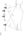
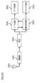
図1Aは、いくつかの実施形態に係る、全地球航法衛星システム(GNSS)の概略図を示す。たとえば、N番目の衛星102は、コードおよび搬送波位相測定値を1組の受信機130および131に送信する(120および121)。たとえば、受信機130は、N個の衛星101、103、104、および102から信号110、120を受信するように位置決めされる。同様に、受信機131は、N個の衛星101、103、104、および102から信号121および111を受信するように位置決めされる。DESCRIPTION OF EMBODIMENTS FIG. 1A shows a schematic diagram of a Global Navigation Satellite System (GNSS), according to some embodiments. For example, the
さまざまな実施形態では、GNSS受信機130および131は、異なるタイプのものとすることができる。たとえば、図1Aの具体例としての実施形態では、受信機131は、その位置が既知のベース受信機である。たとえば、受信機131は、地上に設置された受信機とすることができる。対照的に、受信機130は、移動するように構成されたモバイル受信機である。たとえば、受信機130は、携帯電話、車、または列車に搭載することができる。いくつかの実現例では、第2の受信機131は任意であり、大気効果ならびに受信機および衛星の内部クロックの誤差などのさまざまな原因に起因する不確実性および誤差を除去するために用いることができる。 In various embodiments,
いくつかの実施形態の目的は、アンビギュイティ決定のために用いられる推定手順の複雑さを軽減する方法を開示することである。これに加えて、またはこれに代えて、いくつかの実施形態の目的は、モーションモデルおよび測定モデルに基づいて状態推定値を提供する位置推定フィルタのような状態推定器での利用に好適なアンビギュイティ決定方法を提供することである。アンビギュイティ決定は典型的に位置推定における中間ステップに過ぎず、最終目的ではないため、位置推定フィルタが有利であり得る。 An aim of some embodiments is to disclose a method that reduces the complexity of the estimation procedure used for ambiguity determination. Additionally or alternatively, it is an object of some embodiments to provide ambiences suitable for use in state estimators, such as position estimation filters, that provide state estimates based on motion and measurement models. It is to provide a guyity determination method. A position estimation filter may be advantageous because ambiguity determination is typically only an intermediate step in position estimation and not the final goal.
状態推定器の一例は、カルマンフィルタである。カルマンフィルタは、統計ノイズおよびその他の不正確を含む経時観測された一連の測定値を使用し、単一の測定値のみに基づく推定値よりも正確である傾向にある未知の変数の推定値を、この変数に対する同時確率分布を時間枠ごとに推定することによって生成する。カルマンフィルタは、システムの推定状態および推定値の不確実性を追跡する。推定値は、状態遷移のモーションモデルおよび測定値を用いて更新される。いくつかの実施形態は、GNSS受信機のプロセスノイズを受けるモーションモデルと、測定ノイズを受ける衛星信号の測定モデルとを用いて、カルマンフィルタベースのシステムを使用する。 One example of a state estimator is a Kalman filter. The Kalman filter uses a series of measurements observed over time, including statistical noise and other inaccuracies, to produce estimates of unknown variables that tend to be more accurate than estimates based on single measurements alone. A joint probability distribution for this variable is generated by estimating it for each time frame. The Kalman filter tracks the estimated state of the system and the uncertainty of the estimates. The estimates are updated using motion models and measurements of state transitions. Some embodiments use a Kalman filter-based system with a motion model subject to process noise of the GNSS receiver and a measurement model of the satellite signal subject to measurement noise.


図1Bは、いくつかの実施形態によって位置推定に用いられるカルマンフィルタ(KF)の概略図を示す。KFは、線形状態空間モデルにおける状態推定のツールであり、また、ノイズ源が既知でガウス形である(その場合は状態推定値もガウス分布である)ときの最適な推定器である。KFはガウス分布の平均および分散を推定する。平均および分散は、ガウス分布を記述するための2つの必要な量であり、十分統計量であるからである。 FIG. 1B shows a schematic diagram of a Kalman filter (KF) used for position estimation according to some embodiments. KF is a tool for state estimation in linear state-space models and is the best estimator when the noise source is known and Gaussian (in which case the state estimate is also Gaussian). KF estimates the mean and variance of a Gaussian distribution. This is because the mean and variance are two necessary and sufficient statistics to describe a Gaussian distribution.
KFは、状態の初期知識110bから開始して、状態の平均およびその分散111bを求める。次に、KFは、システムのモデルを用いて、次の時間ステップについての状態および分散を予測し(120b)、更新された状態の平均および分散121bを得る。次に、KFは、システムの測定モデルを用いて更新ステップ140bにおいて測定値130bを用いて、更新された状態の平均および分散141bを求める。次に、出力150bが得られ、次の時間ステップ160bについてこの手順が繰り返される。 The KF starts with an initial knowledge of the
いくつかの実施形態では、状態推定器は、受信機の状態を推定するために搬送波位相一重差(single difference:SD)および/または二重差(double difference:DD)を使用し、この状態は受信機の位置を含む。1つの衛星から送信された搬送波信号が2つの受信機によって受信される場合、第1の搬送波位相と第2の搬送波位相との差は、搬送波位相の一重差(SD)と呼ばれる。これに代えて、SDは、受信機に到達する2つの衛星からの信号同士の差と定義することができ、第1の衛星はベース衛星と呼ばれる。たとえば、衛星101からの信号110と衛星102からの信号120との差は1つのSD信号であり、衛星101はベース衛星である。図1Aの1対の受信機131および130を用いて、2つの衛星からの無線信号から得られる搬送波位相におけるSD同士の差は、搬送波位相の二重差(DD)と呼ばれる。搬送波位相差を波長数に変換すると、たとえば、L1 GPS(および/またはGNSS)信号の場合はλ=19cmに変換すると、これは小数部分および整数部分によって分けられる。測位装置は小数部分を測定することができるが、整数部分を直接測定することはできない。したがって、整数部分は整数バイアスまたは整数アンビギュイティと呼ばれる。 In some embodiments, the state estimator uses carrier phase single difference (SD) and/or double difference (DD) to estimate the state of the receiver, which state is Contains the position of the receiver. When a carrier signal transmitted from one satellite is received by two receivers, the difference between the first carrier phase and the second carrier phase is called the single difference (SD) of the carrier phases. Alternatively, SD can be defined as the difference between the signals from two satellites reaching the receiver, the first satellite being called the base satellite. For example, the difference between
一般に、GNSSは複数のコンステレーションを同時に使用して受信機状態を判定することができる。たとえば、GPS、Galileo、Glonass、およびQZSSは同時に使用可能である。衛星システムは典型的に、最大で3つの異なる周波数帯で情報を送信し、周波数帯ごとに、各衛星がコード測定値および搬送波位相測定値を送信する。これらの測定値は、一重差または二重差として組合せることができる。一重差は、基準衛星とその他の衛星との差を取ることを含み、二重差は、対象の受信機と既知の静止位置を有するベース受信機との差も取ることを含む。 In general, GNSS can use multiple constellations simultaneously to determine receiver conditions. For example, GPS, Galileo, Glonass and QZSS can be used simultaneously. Satellite systems typically transmit information on up to three different frequency bands, with each satellite transmitting code and carrier phase measurements for each frequency band. These measurements can be combined as single differences or double differences. A single difference involves taking the difference between the reference satellite and the other satellite, and a double difference involves taking the difference also between the target receiver and a base receiver with a known stationary position.


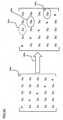
図1Aに示される衛星の場合、SDおよびDDは任意に組合せた衛星同士の間に形成され得る。図1Dは、見通し線(LOS)内に5つの衛星がある場合に衛星間の1つの周波数について形成され得るSDの組合せの一例を示す。衛星の異なる組合せの測定値は、本明細書において測定行列と称する図1Dの行列として表すことができる。測定行列の各要素は、少なくとも1対の一意の衛星のSDまたはDD測定値である。異なる衛星を異なるペアにグループ分けして、測定行列の次元を増やすことができる。各測定値yijは、位置推定に使用可能な情報を所持している。そのため、測定行列全体を位置推定に使用することが可能であり得る。たとえば、衛星101をベース受信機として使用すると、SD測定値y12、y13、y14、およびy15が形成され得る。同様に、衛星102をベース衛星として使用すると、対応するSDは、y21、y23、y24、およびy25である。一般に、M個の衛星およびN個の周波数の場合、(M-1)NM/2個の可能な組合せが存在する。For the satellites shown in FIG. 1A, SD and DD can be formed between any combination of satellites. FIG. 1D shows an example of SD combinations that can be formed for one frequency between satellites when there are five satellites within the line of sight (LOS). The measurements of different combinations of satellites can be represented as the matrix of FIG. 1D, referred to herein as the measurement matrix. Each element of the measurement matrix is an SD or DD measurement of at least one pair of unique satellites. Different satellites can be grouped into different pairs to increase the dimension of the measurement matrix. Each measurement yij carries information that can be used for position estimation. As such, it may be possible to use the entire measurement matrix for position estimation. For example, using

いくつかの実施形態は、測定行列の異なる要素は位置推定フィルタに対して異なる情報価値を有し得るという認識に基づいている。たとえば、GNSS受信機に対して同一のLOS上の1対の衛星位置は、異なるLOS上に位置する1対の衛星よりも情報価値が低い。それらは受信機の同じ幾何学的情報を提供するからである。 Some embodiments are based on the recognition that different elements of the measurement matrix can have different informational value to the position estimation filter. For example, a pair of satellite positions on the same LOS to a GNSS receiver is less informative than a pair of satellites on different LOS. because they provide the same geometrical information of the receiver.
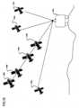
図1Eは、測定行列を形成する異なる測定値は異なる情報量を所持し得るという異なる実施形態の認識を示す概略図を示す。同図は、受信機110eと、7つの衛星120e~190eとを示す。状態推定器(たとえばKF)に4つの衛星を使用すると仮定する。衛星120e、130e、140e、および150eは受信機110eから同一線上に位置している。それらは、同じ仰角からであるが異なる距離測定値を提供する。つまり、それらは、測定ノイズ、すなわち受信機の位置測定におけるノイズに対する感度が等しい。しかしながら、衛星170e、180e、および190eは仰角が異なる。つまり、測定ノイズは受信機位置の不確実性に異なる影響を与える。したがって、異なる衛星は受信機位置に関する異なる情報を提供する。 FIG. 1E shows a schematic diagram illustrating the recognition of different embodiments that different measurements forming a measurement matrix may carry different amounts of information. The figure shows a
たとえば、GNSSでは、SDに使用するベース衛星は、最高仰角を有する衛星である。この衛星は、マルチパスによる障害がない可能性が高いからである。図1Fを参照して、衛星101が最高仰角を有する場合、これは、測定値y12、y13、y14、およびy15のセット110fが、推定に使用されるように測定行列110fから選択された測定値であることを意味する。しかしながら、いくつかの実施形態は、どの衛星をベース衛星として使用するかを決定する要因は、たとえば衛星の物理的位置および環境外乱など、多数あるという理解に基づいている。図1Eを再び参照して、衛星190eは、全衛星の中で最高仰角を有する。したがって、190eとその他の衛星との差としてSDを形成し、4つのSD測定値を状態推定器において使用するとして選択することが自然である。しかしながら、代わりに、異なる衛星をベース衛星として用いてSD測定値を形成することが、衛星間のさらなる幾何学的多様性が提供されるため、有利な場合がある。For example, in GNSS, the base satellite used for SD is the satellite with the highest elevation angle. This satellite is likely free of multipath interference. Referring to FIG. 1F, if
いくつかの実施形態は、位置に関する最大総情報を有する予め定められた数の測定値を選択することが可能であるという認識に基づいている。選択される測定値の数は計算的観点から予め定められているが、測定値は情報価値の観点に基づいて利用可能な測定値から選択されるので、選択された組合せは、受信機ハードウェアの計算上の制限に従いながら、状態推定の最大精度を提供する。たとえば、いくつかの実施形態は、測定値110fを選択するのではなく、測定値のセットに関して情報の損失を最小化する測定値のサブセット120fを選択する。たとえば、この情報は、GNSS受信機の位置を推定するために使用される測定値のコスト関数である。したがって、情報の損失は、測定行列100fのすべての測定値を入力として有するコスト関数と、測定値のサブセット(たとえばサブセット110fまたは120f)を入力測定値として有するコスト関数との差である。 Some embodiments are based on the recognition that it is possible to select a predetermined number of measurements that have the maximum total information about the position. Although the number of measurements selected is predetermined from a computational point of view, measurements are selected from the available measurements based on an informative point of view, so the selected combination is provides maximum accuracy of state estimation while adhering to the computational limits of For example, rather than selecting
受信機の位置は、受信機の状態の一部であり、これは未知であり、状態推定器(たとえばKF)によって推定される。状態推定器は、本質的に、位置情報に小さな誤差を生じさせる。そのため、いくつかの実施形態は、測定情報を求めるためには、受信機の粗位置を知るだけで十分であるという認識に基づいている。 The position of the receiver is part of the state of the receiver, which is unknown and estimated by a state estimator (eg KF). The state estimator inherently introduces small errors in the position information. Therefore, some embodiments are based on the realization that it is sufficient to know the coarse position of the receiver in order to determine the measurement information.
図1Gは、受信機の粗位置を用いて衛星130gの測定情報を求める一実施形態の認識を示す図である。受信機は位置110gにあるが、測定の結果として位置推定誤差115gが生じる。つまり、状態推定器は受信機が位置120gにあると考えている。しかしながら、この誤差は、受信機110gと衛星130gとの間の距離125gよりもはるかに小さい。したがって、衛星130gを用いて測定情報を求めることは、受信機の実際の位置の粗い知識を使用することの影響を受けない。これは、搬送波信号の位相を使用せずにコード信号からGNSSシステムにおける粗位置を推定することができるため、有利である。たとえば、粗位置の推定は、コード信号のうちの少なくとも1つの最小二乗解を用いて行うことができ、または、いくつかのエポック中に収集されたコード信号のセットを最適化することによって行うことができる。 FIG. 1G is a diagram illustrating the recognition of one embodiment that uses the receiver's coarse position to determine measurement information for
たとえば、一実施形態では、コスト関数は、入力測定値のフィッシャー情報行列の関数である。これは、カルマンフィルタなどの確率位置推定フィルタにとって有利である。なぜなら、フィッシャー情報量は、情報量を確率的に測定する、すなわち、Xをモデル化する分布の未知のパラメータθについてXが所持している観測可能な確率変数として測定するからである。そのため、いくつかの実施形態では、測定値のサブセットを選択するために、実施形態は、コード信号において提供される受信機の粗位置に関して、測定値のセットのフィッシャー情報行列の要素を最適化する。たとえば、最適化手順は、フィッシャー情報行列の要素を最適化することによって、コード信号によって規定される分解能を有する受信機の粗位置の分散を最小化する測定値のサブセットを返す。 For example, in one embodiment the cost function is a function of the Fisher information matrix of the input measurements. This is advantageous for probabilistic location filters such as the Kalman filter. This is because Fisher's information measures the amount of information probabilistically, i.e., as an observable random variable that X carries with respect to the unknown parameter θ of the distribution that models X. Therefore, in some embodiments, to select a subset of measurements, embodiments optimize the elements of the Fisher information matrix of the set of measurements with respect to the coarse position of the receiver provided in the code signal. . For example, the optimization procedure returns the subset of measurements that minimizes the variance of the coarse position of the receiver with the resolution defined by the code signal by optimizing the elements of the Fisher information matrix.
図2Aは、いくつかの実施形態に係る、モーションデータと、1組のGNSS衛星101、102、103、104から送信された搬送波信号とコード信号との組合せを含む衛星信号の測定値とを受信する(210a)ように構成されたGNSSを用いて、移動中の可能性がある受信機130の状態を追跡する方法の1回の反復のフローチャートを示す。また、本明細書において使用する場合、このような受信機130はGNSS受信機である。各衛星信号の各測定値は、衛星によって送信された衛星信号と別の衛星信号との間の一重差および/または二重差を含むことにより、衛星の位置に対する衛星信号の受信機の相対位置を含み、各搬送波信号は、衛星101、102、103、または104と受信機130との間を移動した搬送波信号の未知の整数の波長およびノイズとして搬送波位相アンビギュイティを含み、各衛星信号のすべての可能な測定値は測定値のセットを形成する。 FIG. 2A illustrates receiving motion data and satellite signal measurements comprising a combination of carrier and code signals transmitted from a set of
本方法は、受信機の以前の状態を受信機の現在の状態に関係付ける、プロセスノイズを受ける確率モーションモデルと、搬送波信号の搬送波位相アンビギュイティを使用して衛星信号の測定値のサブセット215aを受信機の現在の状態に関係付ける、測定ノイズを受ける確率測定モデルとを、メモリから取出す(222a)。測定値のサブセットの最大サイズは、予め定められて固定されている。本方法はまた、モーションモデルおよび測定モデルによって推定された受信機の状態の同時確率を用いて受信機の状態を追跡するように構成された推定器を取出す(223a)。 The method uses a probabilistic motion model subject to process noise that relates the previous state of the receiver to the current state of the receiver, and the carrier phase ambiguity of the carrier signal to generate a
次に、本方法は、予め定められた数の測定値225aを選択し(220a)、モーションデータを用いるモーションモデル222aと、受信機の以前の状態と、選択された測定値のサブセット225aを用いる測定モデル222aとを用いて状態推定器を実行して(230a)、モーションモデルおよび測定モデルを用いて受信機の状態の同時確率分布235aを求め、同時分布235aから受信機の状態245aを判定する(240a)。さまざまな実施形態では、本方法は、測定値のセットに215aに関して情報の損失を最小化する測定値のサブセット225aを選択する(220a)。 Next, the method selects (220a) a predetermined number of
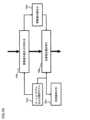
図2Bは、いくつかの実施形態に係る、GNSS受信機の状態を追跡するシステム200のブロック図を示す。状態推定システム200は、受信機の状態の変化を示すモーションデータと、衛星信号(すなわち、1組のGNSS衛星から送信された搬送波信号およびコード信号)の測定値とを受付けるための入力インターフェイス210を含み、各搬送波信号は、衛星と受信機との間を移動した搬送波信号の未知の整数の波長として搬送波位相アンビギュイティを含み、各衛星信号の測定値は、衛星によって送信された衛星信号と別の衛星信号との間の一重差を含むことにより、衛星の搬送波信号の整数アンビギュイティおよびノイズを受ける衛星の位置に対する衛星信号の受信機の相対位置を含み、各衛星信号のすべての可能な測定値は測定値のセットを形成する。システム200は、ハンドヘルドデバイス、車、飛行機、または列車のような、受信機240が配置される複数のデバイスの内部に実装することができる。これに加えて、またはこれに代えて、システム200はデバイスに通信可能に接続することができ、すなわち受信機240はシステムの内部に物理的に存在しない。 FIG. 2B shows a block diagram of a
システムはまた、受信機の以前の状態を受信機の現在の状態に関係付ける、プロセスノイズを受けるモーションモデル281と、受信機240によって受信された搬送波信号およびコード信号の測定値を、搬送波信号の搬送波位相アンビギュイティを使用して受信機の現在の状態に関係付けるとともに、衛星信号の測定値のサブセットを受信機の現在の状態に関係付ける測定モデル282とを格納するメモリ280を含む。測定値のサブセットの最大サイズは、予め定められて固定されている。測定モデルは、測定ノイズを受ける確率モデルである。衛星送信機および受信機210の固有のランダムノイズおよび誤差に起因して、モーションモデルおよび測定モデルは確率的であり、したがって、任意の所与のエポックにおける搬送波位相アンビギュイティのいくつかの可能な値が、異なる確率を有するそれらのモデルと整合することが可能になる。メモリ280はまた、他の実施形態によって記載されている整数値の1組の可能な組合せを格納する(284a)ことができる。 The system also uses a
システム200は、測位システムを補助するのに役立ち得る追加のセンサ220を含み得る。たとえば、センサ220は、慣性計測装置(IMU)、カメラ、装輪車両に搭載される場合のホイールエンコーダ、レーザを含み得る。たとえば、IMUおよびホイールエンコーダが車に接続されているとき、これらのIMUおよびホイールエンコーダを車両のモーションモデルに用いることにより、測位システムの精度をこれらのIMUおよびホイールエンコーダがない場合に可能な精度よりも改善することができる。
システム200は、状態推定器285を用いて受信機の状態を追跡するためのプロセッサ230を含む。さらに、プロセッサ230は、測定値のセットに関して測定値のサブセットを選択する(231)ように構成される。プロセッサ230はまた、モーションモデル281と測定モデル282とを併用することによって受信機の状態210を判定する少なくとも1つの状態推定器232を実行するおよび/または動作させるように構成される。各状態推定器は、モーションモデル281および測定モデル282に関して受信機の状態210の同時確率分布を求め、他の状態推定器と同時におよび/または順次にプロセッサ230によって実行することができる。複数の状態推定器を使用することは、たとえば、正確さについて調査される整数アンビギュイティの仮説が複数ある場合に有用であり得る。これは本発明の他の実施形態によってカバーされている。
これに代えて、またはこれに加えて、少なくともいくつかの異なる状態推定器232の測定モデルは、1組の可能な組合せから選択された搬送波位相アンビギュイティの整数値の異なる組合せ231を含む。たとえば、各状態推定器232は、測定モデル282を、整数の組合せ231から選択された搬送波位相アンビギュイティの整数値のその対応する一意の組合せとともに用いる。次に、プロセッサは、搬送波信号およびコード信号の測定値に従って、受信機の位置の最高同時確率を有する状態推定器を用いて受信機の状態を判定する(260)。このように、搬送波位相アンビギュイティの推定は状態推定器232の外部に移される。これは、搬送波位相アンビギュイティが非線形に変化しても線形位置推定器が動作することができるので、有利である。 Alternatively or additionally, at least some
IMUは、3軸加速度計、3軸ジャイロスコープ、および/または磁力計を含み得る。IMUは、速度、向き、および/または他の位置関連情報をプロセッサ230に与えることができる。いくつかの実施形態では、IMUは、測定された情報を、カメラによる各画像フレームの捕捉と同期して出力することができる。いくつかの実施形態では、IMUの出力は、一部、プロセッサ230が、センサ測定値をフュージングするために、および/またはフュージングされた測定値をさらに処理するために、使用される。 An IMU may include a 3-axis accelerometer, a 3-axis gyroscope, and/or a magnetometer. The IMU can provide speed, orientation, and/or other location-related information to
システム200は、1つ以上の信号を送信可能な送信機250を含み得る。たとえば、送信機250は、受信機240の状態を、他のセンサとフュージングして使用される他の推定方法に送信して、精度を改善することができる。受信機240および送信機250は、1つ以上のタイプの無線通信ネットワークを通じて送受信可能である。受信機240および送信機250は、IEEE802.11規格ファミリに基づき得るフェムトセル、Wi-Fi(登録商標)ネットワークもしくは無線ローカルエリアネットワーク(WLAN)、IEEE802.15x規格ファミリに基づくBluetooth(登録商標)、近距離無線通信(NFC)、ネットワーク等の無線パーソナルエリアネットワーク(WPANS)、および/またはLTE、WiMAX等の無線ワイドエリアネットワーク(WWAN)等であるがこれらに限定されないさまざまな技術に基づいて無線ネットワークとの通信を可能にすることができる。システム200はまた、コントローラエリアネットワーク(CAN)バスなどの、有線ネットワークを介した通信用の1つ以上のポートを含み得る。
メモリ280は、搬送波位相測定値と、センサ220によって提供されたデータとを格納する(286)ことができる。たとえば、いくつかの実現例では、メモリ280は、受信機が設置されている物理的構造物の幾何学的形状284と、衛星と受信機との間の幾何学的関係283とを格納する。一般に、メモリ280は、任意のデータ記憶メカニズムを表し得る。メモリ280は、たとえば、一次メモリおよび/または二次メモリを含み得る。一次メモリは、たとえば、ランダムアクセスメモリ、読取り専用メモリ等を含み得る。図2Bではプロセッサ230とは別個であるとして示されているが、一次メモリの全部または一部をプロセッサ230の内部に設けることができる、またはそうでなければプロセッサ230と同一の場所に配置することができる、および/またはプロセッサ230に結合することができることが理解されるべきである。
システム200内の異なるコンポーネントは、接続250を通じて互いに作動的に結合することができる。接続250は、バス、ライン、ファイバ、リンク、またはその組合せを含み得る。 Different components within
プロセッサ230は、ハードウェア、ファームウェア、およびソフトウェアの組合せを用いて実現することができる。プロセッサ230は、センサフュージョンおよび/またはフュージングされた測定値をさらに処理する方法に関連する計算手順またはプロセスの少なくとも一部を実行するように構成可能な1つ以上の回路を表し得る。プロセッサ230は、メモリ280から命令および/またはデータを引き出す。プロセッサ230は、1つ以上の特定用途向け集積回路(ASIC)、中央処理装置および/またはグラフィック処理装置(CPUおよび/またはGPU)、デジタル信号プロセッサ(DSP)、デジタル信号処理デバイス(DSPD)、プログラマブルロジックデバイス(PLD)、フィールドプログラマブルゲートアレイ(FPGA)、コントローラ、マイクロコントローラ、マイクロプロセッサ、埋込みプロセッサコア、電子デバイス、本明細書に記載の機能を実行するように設計されたその他の電子ユニット、またはその組合せを用いて実現することができる。
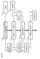
図2Cは、いくつかの実施形態によって用いられる受信機のブロック図を示す。それらの実施形態では、マルチパスの存在を検出する(207c)測定値は、位置を推定するプロセスの一部として受信機において元々計算されている。アンテナ201cの後であって取得203cの前において、受信信号は、各衛星によって発せられた信号の和で構成される。増幅器202cは、さらなる処理のために信号を増強するように設計される。取得203cは、受信した各衛星信号の位相および周波数の推定値を供給することによって追跡プロセスを初期化する。追跡ユニットは、搬送波追跡206cおよびコード追跡204cのために、各衛星信号の位相および周波数の測定値を経時的に推定および提供するタスクを遂行する。コード追跡204cは、データメッセージを判定して処理する(205c)ために用いられる。搬送波追跡206cは、マルチパスを判定する(207c)ために用いられる。 FIG. 2C shows a block diagram of a receiver used by some embodiments. In those embodiments, the measurements that detect the presence of multipath (207c) are originally computed at the receiver as part of the process of estimating position. After
GNSS受信機の中には、1つの受信機に対して数本のアンテナを有し得るものもあるが、数本のアンテナとそれと同数の受信機との組合せが想定可能である。一実施形態は、アンテナとして、複数のアンテナとそれと同数の受信機とを用いる。アンテナは空間的に離間しており、これにより、受信機が同じ衛星信号上の観測された搬送波周波数同士の差を検出することができる。 Some GNSS receivers may have several antennas per receiver, but combinations of several antennas and the same number of receivers are conceivable. One embodiment uses multiple antennas and an equal number of receivers as antennas. The antennas are spatially separated so that the receiver can detect differences between observed carrier frequencies on the same satellite signal.
いくつかの実施形態は、どのSD測定値を状態推定に使用するかの判断は最適化によって行うことができるという知識に基づいている。具体的には、一実施形態は、衛星の位置および受信機の位置を用いて、図1Dの測定行列における各SD測定値に利用可能な情報を定量化することができるという事実に基づいている。各SD測定値の情報の定量化に基づいて、予め定められた最大数の衛星の影響下にある情報の損失を最小化する衛星の組合せを、測定値のコスト関数を最適化することによって求めることができる。この情報の損失は、測定値のセットを測定値として有するコスト関数と、測定値のサブセットを測定値として有するコスト関数との差である。 Some embodiments are based on the knowledge that determining which SD measurements to use for state estimation can be done by optimization. Specifically, one embodiment is based on the fact that satellite positions and receiver positions can be used to quantify the information available for each SD measurement in the measurement matrix of FIG. 1D. . Based on the quantification of the information in each SD measurement, determine the satellite combination that minimizes the loss of information under the influence of a predetermined maximum number of satellites by optimizing the cost function of the measurements. be able to. This loss of information is the difference between a cost function that has a set of measurements as measurements and a cost function that has a subset of measurements as measurements.
図3Aは、一実施形態に係る、測定値のセットに関して測定値のサブセットの情報の損失を最小化する最適化手順の結果を示す。全測定行列310aは10個の一意の測定値からなる。この例では、測定値の最大数が3に設定されていることに基づいて、情報の損失を最小化する(320a)と、測定値331a、332a、および333aが、使用すべき最良の測定値として選択される。 FIG. 3A shows the results of an optimization procedure that minimizes information loss for a subset of measurements with respect to a set of measurements, according to one embodiment. The
一実施形態は、フィッシャー情報量を用いることで測定情報を確率的に定量化することができることを認識している。フィッシャー情報量は、観測可能な確率変数が、その変数をモデル化する分布の未知のパラメータについて所持している情報量を測定する方法である。 One embodiment recognizes that the measurement information can be probabilistically quantified using Fisher information. Fisher information is a method of measuring the amount of information an observable random variable possesses about unknown parameters of the distribution that models that variable.
いくつかの実施形態は、フィッシャー情報行列(FIM)を利用して、取得された測定値を低次元部分空間に射影し、推定値の平均二乗誤差(MSE)に関して推定器性能を最小限に劣化させる射影測定値を見つけるための最適化プログラムを定式化する。射影測定値を用いることにより、元の推定器の性能を保持しつつ大幅な計算高速化が達成される。 Some embodiments utilize the Fisher Information Matrix (FIM) to project the acquired measurements into a low-dimensional subspace, minimizing the degradation of the estimator performance in terms of mean squared error (MSE) of the estimates. We formulate an optimization program to find the projection measurements that By using projective measurements, a significant computational speedup is achieved while retaining the performance of the original estimator.


図4Aは、一実施形態に係る、測定値のサブセットを選択する方法220aのフローチャートを示し、この方法はプロセッサによって実行される。まず、本方法は、少なくとも1つのコード信号に対応する受信機の粗位置411aを求める(410a)。たとえば、一実現例では、粗位置は、粗位置のコード信号への適合度を最適化することによって、たとえば最小二乗問題を解くことによって、求められる。本方法は、粗位置411aおよび測定モデル419aを用いて、粗位置を測定モデルに挿入することによってFIM421aを求める(420a)。次に、本方法は、測定値のフルセットのFIMに関して減少したFIMにおける情報の損失を最小化することによって、FIMを減少したFIM(すなわち、測定値のサブセットのサイズを有する測定値のサブセットのFIM)に減少させる射影演算子431aを求める(430a)。最後に、本方法は、全測定行列に射影演算子を適用して測定値のサブセットを生成する(440a)。 FIG. 4A shows a flowchart of a

いくつかの実施形態は、CRBの最小化は、数値的方法が必要な非凸最適化問題であるという理解に基づいている。一実施形態では、CRBを最適化する射影演算子を求めることは、終了条件が満たされるまで反復的に実行される。 Some embodiments are based on the understanding that CRB minimization is a non-convex optimization problem that requires numerical methods. In one embodiment, finding the projection operator that optimizes the CRB is performed iteratively until a termination condition is met.

本方法は、位置は不確実であるが、その不確実性は受信機と衛星との間の距離よりもはるかに小さいという理解に基づいている。たとえば、図1Gを参照して、コード測定値を用いて受信機位置を推定すると、数メートルのオーダの推定誤差が生じる。しかしながら、受信機と衛星との間の距離は数千キロメートルであり得る。一実施形態は、これを利用して、たとえばコード測定値を用いて粗位置を求めることにより、入力測定値の関数としてCRBを求める。 The method is based on the understanding that position is uncertain, but that uncertainty is much smaller than the distance between the receiver and the satellite. For example, referring to FIG. 1G, using code measurements to estimate receiver position results in an estimation error on the order of several meters. However, the distance between the receiver and the satellite can be thousands of kilometers. One embodiment takes advantage of this to determine CRB as a function of input measurements, for example, by determining coarse position using code measurements.


一実施形態は、導関数を求めるためにはランク条件を満たす必要があるという認識に基づいている。別の実施形態は、利用可能なSDまたはDD衛星信号が少なくとも3つあればいつでもランク条件が満たされることを理解している。一実施形態では、このランク制約は、最適化問題にランク制約を加えることによって課される。 One embodiment is based on the recognition that the rank condition must be satisfied in order to find the derivative. Another embodiment realizes that the rank condition is met whenever there are at least three SD or DD satellite signals available. In one embodiment, this rank constraint is imposed by adding a rank constraint to the optimization problem.


収束基準が満たされた場合(440d)、本方法は射影演算子を出力し、満たされない場合、本方法は更新された射影演算子を用いて偏導関数を求める(410d)。 If the convergence criterion is met (440d), the method outputs the projection operator; otherwise, the method uses the updated projection operator to find the partial derivative (410d).
いくつかの実施形態は、線形化によってCRBが近似するが、衛星と受信機との間の距離が大きいので線形化の影響は無視できるという事実を認識している。言い換えれば、誤差が数メートル以内である限り、粗位置を用いても線形化誤差にはほとんど影響がない。 Some embodiments recognize the fact that although linearization approximates the CRB, the distance between the satellite and the receiver is so large that the linearization effect is negligible. In other words, using the coarse position has little effect on the linearization error as long as the error is within a few meters.
一実施形態は、アルゴリズム的観点から、衛星の組合せは全衛星を含む必要はないという理解に基づいている。たとえば、5つの衛星があり、そのうちの4つを選択する場合を考える。その場合、全衛星測定値を組合せるよりも、第1の衛星の測定値の4分の1と第4の衛星の測定値の4分の3とを用いる方がよい場合もある。言い換えれば、測定値を形成する衛星測定値の組合せは、衛星の非整数の組合せである。直観的には、その理由は、FIMがシステムにおける不確実性を捕捉するからであり、全衛星の組合せは最高確率を有するが、このような組合せの正確さには一定の不確実性があるため、非整数の組合せを選択する方がMSEの観点から安全であるからである。 One embodiment is based on the understanding that, from an algorithmic point of view, a combination of satellites need not include all satellites. For example, if there are 5 satellites and 4 of them are selected. In that case, it may be better to use one-fourth of the first satellite's measurements and three-fourths of the fourth's measurements rather than combining all satellite measurements. In other words, the combination of satellite measurements forming a measurement is a non-integer combination of satellites. Intuitively, the reason is that the FIM captures the uncertainty in the system, and although the combination of all satellites has the highest probability, there is some uncertainty in the accuracy of such combination. Therefore, it is safer to select non-integer combinations from the viewpoint of MSE.


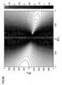
図5A、図5B、および図5Cは、特別に選択した射影演算子の行列要素のうちの2つを変更したときのCRBのレベルセットを示す。レベルセットは、グローバルに非凸であるが、領域の大部分については凸である。さらに、同図は、測定値のサブセットの一部として全衛星を選択することは最適ではないことを示す。言い換えれば、FIMは、測定値のセットの座標系における空間を規定する。測定値のサブセットに対応する空間の表面を見つけることができ、FIMの要素の最大値を有する表面上の点を見つけることができる。 Figures 5A, 5B, and 5C show the CRB level sets when changing two of the matrix elements of a specially selected projection operator. The level set is globally non-convex, but convex over most of the region. Furthermore, the figure shows that selecting all satellites as part of the subset of measurements is not optimal. In other words, the FIM defines the space in the coordinate system of the set of measurements. A surface in space can be found that corresponds to a subset of the measurements, and the point on the surface that has the maximum value of the FIM element can be found.
測定値のサブセットを用いて、さまざまな受信機状態推定器を実現することができる。たとえば、一実施形態は、整数最小二乗ソルバと組合されたカルマンフィルタを使用して、受信機の状態を判定する。 A subset of measurements can be used to implement various receiver state estimators. For example, one embodiment uses a Kalman filter combined with an integer least squares solver to determine the state of the receiver.
図6Aは、一実施形態に係る、状態推定器の1回の反復(230a)の実行例を示す。本方法は、他の実施形態に従って説明した受信機のモーションデータおよびモーションモデルを用いて、以前の状態から現在の状態までの状態を予測する(610a)。次に、本方法は、予測状態に最もよく適合する搬送波位相信号の整数アンビギュイティを求める(620a)。任意の整数ソルバを使用することができる。たとえば、一実施形態は、整数アンビギュイティを求めるために、整数最小二乗ソルバLAMBDAおよびその変形を使用する。本方法は、予測状態を用いて求めた整数アンビギュイティを使用して、測定値のサブセットを用いて状態を推定する(630a)。 FIG. 6A shows an example implementation of one iteration (230a) of the state estimator, according to one embodiment. The method predicts 610a the state from the previous state to the current state using the receiver motion data and motion model described according to other embodiments. Next, the method determines 620a the integer ambiguity of the carrier phase signal that best matches the predicted conditions. Any integer solver can be used. For example, one embodiment uses the integer least squares solver LAMBDA and variants thereof to find integer ambiguities. Using the integer ambiguities determined using the predicted state, the method estimates 630a the state using a subset of the measurements.
他の実施形態は、複数の可能な整数アンビギュイティが存在する場合があり、異なる整数の可能性に対して複数の状態推定器を実行することができるという理解に基づいている。 Other embodiments are based on the understanding that there may be multiple possible integer ambiguities, and multiple state estimators can be implemented for different integer possibilities.
たとえば、図7Aは、異なる整数の可能性に対して複数のカルマンフィルタが実行される、受信機130の状態推定のための方法の1回の反復のフローチャートを示す。 For example, FIG. 7A shows a flowchart of one iteration of the method for state estimation of
本方法は、測定値のセットを用いて、プロセスノイズおよび測定ノイズの一方または組合せによって規定される範囲内で、モーションモデルおよび測定モデル712aの一方または組合せに従って、搬送波信号およびコード信号の測定値と整合するの搬送波位相アンビギュイティの整数値の1組の可能な組合せ715aを求める(710a)。このステップは、状態推定を行うために搬送波位相アンビギュイティを求めようとするのではなく、状態推定のために搬送波位相アンビギュイティの異なる可能な組合せを求めてテストすることが有益であるという理解に基づいている。このように、状態推定のニュアンスをよりよく反映する確率モデルを用いて、最良の搬送波位相アンビギュイティを選択することができる。 Using the set of measurements, the method performs measurements of the carrier signal and the code signal according to one or a combination of the motion model and
そのために、本方法は、モーションモデルおよび測定モデル712aを併用することによって、受信機の状態を判定する一組の状態推定器(たとえば修正カルマンフィルタ)を実行する。各状態推定器は、モーションモデルおよび測定モデル712aに関して受信機の位置の同時確率分布725aを求めるために、搬送波位相アンビギュイティの整数値のその対応する組合せを含む。このように、少なくともいくつかの異なる位置推定器の測定モデルは、1組の可能な組合せ715aから選択された搬送波位相アンビギュイティの整数値の異なる組合せを含むため、搬送波位相アンビギュイティの整数値の組合せを確率的に評価することができる。次に、本方法は、搬送波信号およびコード信号の測定値のサブセットに従って、受信機の状態の最高同時確率を有する状態推定器を用いて受信機の状態を判定する。 To that end, the method implements a set of state estimators (eg, modified Kalman filters) that determine the state of the receiver by jointly using motion and
そのため、いくつかの実施形態は、搬送波位相アンビギュイティの可能な整数値の範囲の推定、および、その範囲からの搬送波位相アンビギュイティの整数値の選択を、測定モデルのノイズのPDFに対するモーションモデルおよび測定モデルの整合性を用いて確率的に行うことができるという認識に基づいている。 As such, some embodiments estimate a range of possible carrier-phase ambiguity integer values, and select an integer value for carrier-phase ambiguity from that range, as a function of the motion of the noise in the measurement model against the PDF. It is based on the recognition that it can be done stochastically using the consistency of models and measurement models.
図7Bは、いくつかの実施形態に係る、搬送波位相アンビギュイティの整数値の可能な組合せを求める(710b)方法のフローチャートを示す。本方法は、プロセッサを用いて実行することができる。モーションモデルのプロセスノイズと整合する受信機の少なくとも1つの位置について、本方法は、少なくとも1つの衛星について、ノイズなし適合度を中心とする測定ノイズのPDF(すなわち、搬送波位相アンビギュイティ、位置、ならびに搬送波信号およびコード信号の測定値の測定モデルへの、ノイズなしの測定モデル)上で、搬送波位相アンビギュイティの浮動小数点値711bをサンプリングする(710b)。 FIG. 7B shows a flowchart of a method for determining 710b possible combinations of integer values of carrier phase ambiguities, according to some embodiments. The method can be performed using a processor. For at least one position of the receiver that matches the process noise of the motion model, the method calculates the PDF of the measured noise (i.e., carrier phase ambiguity, position, and the noise-free measurement model to the measurement model of the carrier and
いくつかの実施形態では、測定ノイズのPDFは、たとえばGNSS受信機の特性に基づいて予め定められている。このように、ノイズなし適合度は、PDF上のサンプリングによってモーションモデルおよび測定モデルの確率ノイズが強調されなくなり、搬送波位相アンビギュイティが位置推定に与える影響が強調される位置に、PDFを配置する。 In some embodiments, the PDF of the measurement noise is predetermined, eg, based on GNSS receiver characteristics. Thus, the noiseless fit places the PDF at a position where sampling on the PDF de-emphasizes stochastic noise in the motion and measurement models, emphasizing the effect of carrier-phase ambiguity on position estimation. .
次に、本方法は、サンプリングされた浮動小数点値の和集合を形成して(720b)、サンプリングされた浮動小数点値をすべて含む和集合721bを生成し、浮動小数点値の和集合を整数ベースで離散化して(720b)、1組のGNSS衛星についての搬送波位相アンビギュティの可能な整数値731bを生成する。最後に、本方法は、すべての衛星についての搬送波位相アンビギュイティの可能な整数値731bを用いて、整数値の1組の可能な組合せ725bを生成する(740b)。 Next, the method forms a
図7Cは、一実施形態に係る、浮動小数点値をサンプリングする方法710bの具体例としての実現例のフローチャートを示す。ただし、浮動小数点値のサンプリング710bは、異なる実施形態によっていくつかの方法で実現される。図7Cの方法は、モーションモデルおよびそのプロセスノイズと整合する浮動小数点値をサンプリングする(709c)。本方法は、サンプリングされた搬送波位相アンビギュイティと、推定位置と、搬送波信号およびコード信号の測定値のセットとを測定モデルに挿入することによって、コード信号および搬送波位相信号の測定値との整合性を求める(711c)。本方法は、測定値との整合性に基づいて、サンプリングされた各浮動小数点値をプロセスノイズおよび測定ノイズの関数として補正し(712c)、補正された浮動小数点値に基づいて測定値のサブセットを用いて状態を補正し(713c)、補正後の測定値との整合性に基づいて各アンビギュイティの確率を更新し(714c)、測定モデルに適合する確率が閾値を上回っている搬送波位相アンビギュイティの浮動小数点値を保持するように、搬送波位相アンビギュイティの補正済みのサンプリングされた浮動小数点値をプルーニングする(715c)。 FIG. 7C shows a flowchart of an exemplary implementation of a
いくつかの実施形態は、モーションモデルおよび測定モデルの確率的性質が、浮動小数点値によって定義される確率密度関数(PDF)によって捉えられるという認識に基づいている。 Some embodiments are based on the recognition that the probabilistic nature of motion models and measurement models is captured by a probability density function (PDF) defined by floating point values.

図8Aは、一実施形態に係る、受信機の可能な状態にわたってPDF831aを用いた、サンプリングされたアンビギュイティの確率の選択を示すグラフを示す。たとえば、PDF831aは、測定モデルの確率分布とすることができる。このような確率分布の形状は、たとえばガウス形状または異なる形状として事前に決定しておくことができ、この確率分布831aの位置は、測定された状態のノイズなし適合度835aを中心とする。 FIG. 8A shows a graph illustrating sampled ambiguity probability
一実施形態は、測定値のサブセットを用いて、測定された状態を中心とする測定モデルの確率分布831aを用いて、受信機の状態および/またはアンビギュイティの確率分布を求める。そのため、本実施形態は、受信機の状態およびアンビギュイティの確率分布上のアンビギュイティおよび推定位置の配置に従って、サンプリングされた各アンビギュイティが真のアンビギュイティを表す確率を求めることができる。 One embodiment uses a subset of the measurements to determine the probability distribution of the receiver states and/or ambiguities using the
たとえば、本実施形態は、搬送波信号およびコード信号の測定値のサブセットのモデルにアンビギュイティを与える。本実施形態は、測定された状態に対するアンビギュイティ821aを有する測定値のサブセットの測定モデルの適合度に対応する点823aにおける受信機の状態にわたるPDFの値822aを、アンビギュイティが正確である確率として選択する。 For example, the present embodiment imposes ambiguities in the model for a subset of the carrier and code signal measurements. The present embodiment determines the
いくつかの実施形態では、サンプリングされたアンビギュイティの確率が閾値よりも低い場合、対応するアンビギュイティは、上記確率を求めることから除去され、より高い確率を有するサンプリングされたアンビギュイティに置き換えられる。このようにすることによって、正しいアンビギュイティである可能性がより高いサンプリングされたアンビギュイティのみを確実に選ぶことができるようになる。 In some embodiments, if the probability of a sampled ambiguity is lower than a threshold, the corresponding ambiguity is removed from determining the probability and replaced with the sampled ambiguity with the higher probability. be replaced. By doing so, it is possible to ensure that only sampled ambiguities that are more likely to be correct ambiguities are selected.

図8Bは、いくつかの実施形態に係る、サンプリングされた搬送波位相アンビギュイティの浮動小数点値の確率の概略図を示す。図8Bは、確率821b、822b、823b、824b、および825bが割り当てられている搬送波位相アンビギュイティの5つの浮動小数点値を示す。これらの確率は、可能なアンビギュイティの正確な範囲とは異なる離散分布を構成する。一実施形態は、搬送波位相アンビギュイティの浮動小数点値の確率を内挿および外挿して連続した確率密度関数を形成し、閾値を上回る連続した確率密度関数の少なくとも1つの区間を搬送波位相アンビギュイティの整数値の範囲として選択する。 FIG. 8B shows a schematic diagram of probability of floating-point values of sampled carrier phase ambiguities, according to some embodiments. FIG. 8B shows five floating point values of carrier phase ambiguity that are assigned
図8Cは、いくつかの実施形態に係る、サンプリングされた搬送波位相アンビギュイティの浮動小数点値の確率を内挿および外挿する方法の結果を示す図である。内挿は、点同士の間に曲線830Cを接続し、外挿は、離散点を越えて曲線830Cを延長させる。 FIG. 8C illustrates results of a method of interpolating and extrapolating the probability of floating-point values of sampled carrier phase ambiguities, according to some embodiments. Interpolation connects curve 830C between points, and extrapolation extends curve 830C beyond discrete points.
いくつかの実施形態では、曲線830cのある区間が選択される。たとえば、図8Dは、領域840dが選択される状況を示す。つまり、この領域に対応するアンビギュイティ値は、1組の可能な整数値の基礎を形成する。この選択はいくつかの方法で行うことができる。たとえば、一実施形態は、閾値850dを上回る連続PDFの区間を選択する。 In some embodiments, a section of
一実施形態は、選択された整数値に基づいて1組の状態推定器を実行する。各状態推定器は、測定モデルにおいて一意の1組のアンビギュイティを使用する。たとえば、一実施形態は1組のカルマンフィルタを使用する。カルマンフィルタは、モーションモデルを用いて状態を推定し、状態推定器用に選択された搬送波位相アンビギュイティの整数値に従って調整された搬送波信号およびコード信号の測定値のサブセットを有する測定モデルを用いて、推定状態を調整する。カルマンフィルタは、測定値のサブセットを用いて、調整された状態と測定モデルとの整合性に基づいて位置の同時確率を求める。 One embodiment runs a set of state estimators based on the selected integer values. Each state estimator uses a unique set of ambiguities in the measurement model. For example, one embodiment uses a set of Kalman filters. a Kalman filter estimating a state using a motion model, using a measurement model having a subset of measurements of the carrier and code signals adjusted according to an integer value of carrier phase ambiguity selected for the state estimator, Adjust the estimated state. A Kalman filter uses a subset of the measurements to determine joint probabilities of locations based on the alignment of the adjusted state with the measurement model.


いくつかの実施形態は、推定値の品質、すなわち各推定器の確率を評価することは、推定値および測定値のサブセットを挿入するときにガウス分布を評価することによって行うことができることを認識している。 Some embodiments recognize that evaluating the quality of the estimates, i.e. the probability of each estimator, can be done by evaluating Gaussian distributions when inserting subsets of estimates and measurements. ing.

整数値の1組の可能な組合せは、たとえば、一定期間の衛星のロックの喪失、より多くの衛星からの信号の受信、またはマルチパス検出に起因して、変化する場合がある。 The set of possible combinations of integer values may change due to, for example, loss of satellite lock for a period of time, reception of signals from more satellites, or multipath detection.
位置推定値を初期化するとき、受信機が位置している場所についての情報がほとんどない場合がある。ベース受信機、カーナビゲーションシステム、またはWi-Fi局から粗い情報を取得できる場合がある。一実施形態は、位置の最初の粗い推定値の周囲の位置をサンプリングして受信機の位置を生成し、この場合、サンプリングの広がりは、受信機のモデルの不確実性と一致する。 When initializing the position estimate, there may be little information about where the receiver is located. Coarse information may be obtained from base receivers, car navigation systems, or Wi-Fi stations. One embodiment generates the receiver's position by sampling positions around an initial coarse estimate of the position, where the sampling spread matches the receiver's model uncertainty.
別の誤差源は、1つ以上の衛星の喪失である。これによって、位置情報が失われ、現在の推定値が信頼できないものとなる。一実施形態は、直近の既知の状態の近傍において受信機の状態をサンプリングして、モーションモデルのプロセスノイズと整合する受信機の状態を生成することによって、これを解決する。たとえば、一実施形態は、直近の既知の状態推定値を追跡し、サンプルがプロセスノイズと整合するようにこの推定値の周囲をサンプリングし、サンプリングされた状態をモーションモデルを用いて反映させる。 Another source of error is the loss of one or more satellites. This causes the loss of position information and makes the current estimate unreliable. One embodiment solves this by sampling the receiver state in the vicinity of the most recent known state to produce a receiver state that matches the process noise of the motion model. For example, one embodiment tracks the last known state estimate, samples around this estimate such that the samples match the process noise, and reflects the sampled state using a motion model.
本発明の上記実施形態は、数多くのやり方のうちのいずれかで実現することができる。たとえば、これらの実施形態は、ハードウェア、ソフトウェア、またはその組合せを用いて実現してもよい。ソフトウェアで実現する場合、ソフトウェアコードは、任意の適切なプロセッサまたはプロセッサの集まりにおいて、これが1つのコンピュータに設けられていても複数のコンピュータに分散されていても、実行することができる。このようなプロセッサは、1以上のプロセッサが集積回路コンポーネント内にある集積回路として実現してもよい。プロセッサは、任意の適切なフォーマットの回路を用いて実現してもよい。 The above-described embodiments of the invention can be implemented in any of a number of ways. For example, these embodiments may be implemented using hardware, software, or a combination thereof. When implemented in software, the software code can be executed on any suitable processor or collection of processors, whether on one computer or distributed among multiple computers. Such processors may be implemented as integrated circuits, with one or more processors within an integrated circuit component. A processor may be implemented using circuitry in any suitable format.
また、本明細書で概要を述べた各種方法またはプロセスは、さまざまなオペレーティングシステムまたはプラットフォームのうちのいずれか1つを採用した1つ以上のプロセッサ上で実行可能なソフトウェアとして符号化されてもよい。加えて、このようなソフトウェアは、複数の好適なプログラミング言語および/またはプログラミングもしくはスクリプトツールのうちのいずれかを用いて記述されてもよく、フレームワークもしくは仮想マシン上で実行される、実行可能なマシン言語コードまたは中間コードとしてコンパイルされてもよい。典型的に、プログラムモジュールの機能は、各種実施形態において所望される通りに組合せても分散させてもよい。 Also, the various methods or processes outlined herein may be encoded as software executable on one or more processors employing any one of a variety of operating systems or platforms. . Additionally, such software may be written using any of a number of suitable programming languages and/or programming or scripting tools, and may be run on a framework or virtual machine, such as an executable It may be compiled as machine language code or intermediate code. Typically the functionality of the program modules may be combined or distributed as desired in various embodiments.
また、本発明の実施形態は、方法として実施されてもよく、その一例が提供されている。この方法の一部として実行される動作の順序は任意の適切なやり方で決められてもよい。したがって、実施形態は、例示されている順序と異なる順序で動作が実行されるように構成されてもよく、これは、いくつかの動作を、例示されている実施形態では一連の動作として示されるが、同時に実行することを含み得る。 Also, embodiments of the present invention may be embodied as a method, an example of which is provided. The order of operations performed as part of the method may be ordered in any suitable manner. Accordingly, embodiments may be configured to perform operations in a different order than the illustrated order, which may cause some operations to be shown as a series of operations in the illustrated embodiment. may include executing concurrently.
本発明を好ましい実施形態の例を用いて説明してきたが、その他の各種応用および修正を本発明の精神および範囲の中で行い得ることが理解されるはずである。したがって、以下の請求項の目的は、本発明の真の精神および範囲に含まれるこのような変形および修正のすべてをカバーすることである。 Although the invention has been described by way of examples of preferred embodiments, it is to be understood that various other applications and modifications can be made within the spirit and scope of the invention. Therefore, it is the object of the following claims to cover all such variations and modifications that fall within the true spirit and scope of the invention.
Claims (20)
Translated fromJapanese前記受信機の状態の変化を示すモーションデータと、1組のGNSS衛星から送信された搬送波信号とコード信号との組合せを含む衛星信号の測定値とを受付けるための入力インターフェイスを備え、各衛星信号の測定値は、衛星信号の少なくとも一重差測定値を含むことにより、前記衛星信号を送信する衛星の位置に対する前記衛星信号の前記受信機の相対位置を表し、前記衛星信号は、前記衛星の前記搬送波信号の整数アンビギュイティおよびノイズを受け、現在の時間ステップにおける各衛星信号のすべての可能な測定値は測定値のセットを形成し、前記システムはさらに、
前記モーションデータに従って前記受信機の以前の状態を前記受信機の現在の状態に遷移させるモーションモデルを格納するように構成されたメモリを備え、前記モーションモデルはプロセスノイズを受ける確率モデルであり、前記メモリはさらに、前記衛星信号の測定値のサブセットを前記受信機の前記現在の状態に関係付ける測定モデルを格納するように構成され、前記測定値のサブセットのサイズは前記測定値のセットのサイズよりも小さく、前記測定モデルは測定ノイズを受ける確率モデルであり、前記メモリはさらに、前記モーションモデルおよび前記測定モデルによって推定された前記受信機の状態の同時確率を用いて前記受信機の状態を追跡するように構成された状態推定器を格納するように構成され、前記システムはさらに、
前記受信機の状態を追跡するためのプロセッサを備え、前記プロセッサは、
前記測定値のセットに関して前記測定値のサブセットにおける情報の損失を最小化することによって前記測定値のサブセットを選択し、
前記モーションデータを用いる前記モーションモデルと、選択された前記測定値のサブセットを用いる前記測定モデルとを用いて前記状態推定器を実行して、前記受信機の状態を推定するように構成される、システム。A system for tracking the status of a Global Navigation Satellite System (GNSS) receiver, comprising:
an input interface for receiving motion data indicative of changes in the state of said receiver and measurements of satellite signals comprising a combination of carrier and code signals transmitted from a set of GNSS satellites; represents the relative position of said receiver of said satellite signal with respect to the position of the satellite transmitting said satellite signal by including at least a single difference measurement of said satellite signal, said satellite signal representing said Subject to integer ambiguities and noise in the carrier signal, all possible measurements of each satellite signal at the current time step form a set of measurements, the system further comprising:
a memory configured to store a motion model that transitions a previous state of the receiver to a current state of the receiver according to the motion data, the motion model being a probabilistic model subject to process noise; The memory is further configured to store a measurement model relating a subset of the satellite signal measurements to the current state of the receiver, the size of the subset of measurements being less than the size of the set of measurements. and the measurement model is a probabilistic model subject to measurement noise, and the memory further tracks the state of the receiver using joint probabilities of the state of the receiver estimated by the motion model and the measurement model. The system is configured to store a state estimator configured to:
a processor for tracking the state of the receiver, the processor comprising:
selecting the subset of measurements by minimizing information loss in the subset of measurements with respect to the set of measurements;
configured to run the state estimator using the motion model using the motion data and the measurement model using a selected subset of the measurements to estimate a state of the receiver; system.
少なくとも1つのコード信号に対応する前記受信機の粗位置を求め、
前記粗位置を前記測定モデルに挿入することによって前記フィッシャー情報行列を求め、
前記フィッシャー情報行列に関して、前記測定値のサブセットのサイズを有する減少したフィッシャー情報行列における前記情報の損失を最小化することによって、前記フィッシャー情報行列を前記減少したフィッシャー情報行列に減少させる射影演算子を求め、
全測定行列に前記射影演算子を適用して、前記測定値のサブセットを生成するように構成される、請求項4に記載のシステム。The processor
determining a coarse position of the receiver corresponding to at least one code signal;
determining the Fisher information matrix by inserting the coarse positions into the measurement model;
With respect to the Fisher information matrix, a projection operator that reduces the Fisher information matrix to the reduced Fisher information matrix by minimizing the loss of information in the reduced Fisher information matrix having the size of the subset of the measurements. seek,
5. The system of claim 4, configured to apply the projection operator to the full measurement matrix to generate the subset of measurements.
終了条件が満たされるまで、前記減少したフィッシャー情報行列のクラメール・ラオの限界(CRB)を最適化する前記射影演算子を反復的に求めるように構成される、請求項6に記載のシステム。The processor further:
7. The system of claim 6, configured to iteratively determine the projection operator that optimizes a Cramer-Rao bound (CRB) of the reduced Fisher information matrix until a termination condition is met.
前記減少したフィッシャー情報行列の逆数の対角要素を合計することによってクラメール・ラオの限界(CRB)を求め、
前記射影演算子に関して前記CRBの偏導関数を求め、
前記偏導関数の方向に前記射影演算子を更新するように構成される、請求項7に記載のシステム。To perform the iterations, the processor:
determining the Cramer-Rao bound (CRB) by summing the diagonal elements of the reciprocal of the reduced Fisher information matrix;
taking partial derivatives of the CRB with respect to the projection operator;
8. The system of claim 7, configured to update the projection operator in the direction of the partial derivative.
前記測定値のサブセットのサイズについて前記CRBを求め、測定値のフルセットについて前記CRBを求め、
前記測定値のセットの前記CRBに対する測定値のサブセットの前記CRBの比が閾値よりも大きい場合、前記測定値のサブセットのサイズを大きくするように構成される、請求項6に記載のシステム。The processor further:
determining the CRB for a subset size of the measurements, determining the CRB for a full set of measurements;
7. The system of claim 6, configured to increase the size of the subset of measurements if the ratio of the CRBs of a subset of measurements to the CRBs of the set of measurements is greater than a threshold.
前記プロセスノイズおよび前記測定ノイズの一方または組合せによって規定される範囲内で、前記モーションモデルおよび前記測定モデルの一方または組合せに従って、前記搬送波信号および前記コード信号の測定値と整合する搬送波位相アンビギュイティの整数値の1組の可能な組合せを求め、
前記モーションモデルと前記測定モデルとを併用することによって前記受信機の状態を判定する1組の状態推定器を実行するように構成され、各状態推定器は、前記モーションモデルおよび前記測定モデルに関して前記受信機の状態の同時確率分布を求め、少なくともいくつかの異なる状態推定器の前記測定モデルは、前記1組の可能な組合せから選択された前記搬送波位相アンビギュイティの整数値の異なる組合せを含む、請求項1に記載のシステム。The estimator is a Kalman filter, and the processor comprises:
Carrier phase ambiguity matching measurements of the carrier signal and the code signal according to one or a combination of the motion model and the measurement model within a range defined by one or a combination of the process noise and the measurement noise. find a set of possible combinations of the integer values of
configured to implement a set of state estimators that determine a state of the receiver by jointly using the motion model and the measurement model, each state estimator executing the determining a joint probability distribution of states of a receiver, wherein said measurement models for at least some different state estimators comprise different combinations of integer values of said carrier phase ambiguities selected from said set of possible combinations; , the system of claim 1.
前記受信機の状態の変化を示すモーションデータを受付けるステップと、
1組のGNSS衛星から送信された搬送波信号とコード信号との組合せを含む衛星信号の測定値を受付けるステップとを備え、各衛星信号の測定値は、衛星によって送信された前記衛星信号と別の衛星信号との間の一重差を含むことにより、前記衛星の前記搬送波信号の整数アンビギュイティおよびノイズを受ける前記衛星の位置に対する前記衛星信号の前記受信機の相対位置を含み、各衛星信号のすべての可能な測定値は測定値のセットを形成し、前記ステップはさらに、
前記測定値のセットに関して情報の損失を最小化する前記測定値のサブセットを選択するステップと、
前記モーションデータを用いる前記モーションモデルと、選択された前記測定値のサブセットを用いる前記測定モデルとを用いて前記状態推定器を実行して、前記受信機の状態を推定するステップとを備える、方法。A method of tracking the state of a Global Navigation Satellite System (GNSS) receiver, the method storing a motion model that transitions a previous state of the receiver to a current state of the receiver according to motion data. wherein the motion model is a probability model subject to process noise and a measurement model relating a subset of satellite signal measurements to the current state of the receiver; The measurement model is a probabilistic model subject to measurement noise, and the state estimator is configured to track the state of the receiver using joint probabilities of the state of the receiver estimated by the motion model and the measurement model. and the processor is coupled to stored instructions for performing the method, the instructions performing the steps of the method when executed by the processor, the steps comprising:
receiving motion data indicative of a change in state of the receiver;
receiving measurements of satellite signals comprising combinations of carrier and code signals transmitted from a set of GNSS satellites, each satellite signal measurement being separate from said satellite signals transmitted by the satellites. of each satellite signal, including the relative position of said receiver of said satellite signal with respect to the position of said satellite subject to integer ambiguities and noise of said carrier signal of said satellite by including single differences between said satellite signals; All possible measurements form a set of measurements, said step further comprising:
selecting a subset of the measurements that minimizes information loss with respect to the set of measurements;
executing the state estimator using the motion model using the motion data and the measurement model using a selected subset of the measurements to estimate the state of the receiver. .
前記コード信号において提供される前記受信機の粗位置に関して、前記測定値のセットのフィッシャー情報行列の要素を最適化することを備える、請求項18に記載の方法。To select the subset of measurements, the method comprises:
19. The method of claim 18, comprising optimizing elements of a Fisher information matrix of the set of measurements with respect to the coarse position of the receiver provided in the code signal.
前記受信機の状態の変化を示すモーションデータを受付けることと、
1組のGNSS衛星から送信された搬送波信号とコード信号との組合せを含む衛星信号の測定値を受付けることとを備え、各衛星信号の測定値は、衛星によって送信された前記衛星信号と別の衛星信号との間の一重差を含むことにより、前記衛星の前記搬送波信号の整数アンビギュイティおよびノイズを受ける前記衛星の位置に対する前記衛星信号の前記受信機の相対位置を含み、各衛星信号のすべての可能な測定値は測定値のセットを形成し、前記方法はさらに、
前記コード信号において提供される前記受信機の粗位置に関して前記測定値のセットのフィッシャー情報行列の要素を最適化することによって、前記測定値のセットに関して情報の損失を減少させるように前記測定値のサブセットを選択することと、
前記モーションデータを用いる前記モーションモデルと、選択された前記測定値のサブセットを用いる前記測定モデルとを用いて前記状態推定器を実行して、前記受信機の状態を推定することとを備える、非一時的なコンピュータ読取可能記憶媒体。A non-transitory computer-readable storage medium on which a processor-executable program for performing a method is implemented, said medium storing a previous state of a receiver according to motion data to a current state of said receiver. , the motion model being a probability model subject to process noise and a measurement model relating a subset of satellite signal measurements to the current state of the receiver, the measurement model is a probabilistic model subject to measurement noise, a state estimator configured to track the state of the receiver using joint probabilities of the state of the receiver estimated by the motion model and the measurement model; The method includes:
receiving motion data indicative of a change in state of the receiver;
receiving measurements of satellite signals comprising combinations of carrier and code signals transmitted from a set of GNSS satellites, each satellite signal measurement being separate from said satellite signals transmitted by the satellites. of each satellite signal, including the relative position of said receiver of said satellite signal with respect to the position of said satellite subject to integer ambiguities and noise of said carrier signal of said satellite by including single differences between said satellite signals; All possible measurements form a set of measurements, the method further comprising:
of the measurements to reduce information loss for the set of measurements by optimizing elements of a Fisher information matrix for the set of measurements with respect to the coarse position of the receiver provided in the code signal. selecting a subset;
executing the state estimator using the motion model using the motion data and the measurement model using a selected subset of the measurements to estimate the state of the receiver. A temporary computer-readable storage medium.
Applications Claiming Priority (3)
| Application Number | Priority Date | Filing Date | Title |
|---|---|---|---|
| US16/789,455 | 2020-02-13 | ||
| US16/789,455US11474263B2 (en) | 2020-02-13 | 2020-02-13 | System and method for GNSS ambiguity resolution |
| PCT/JP2021/006022WO2021162131A1 (en) | 2020-02-13 | 2021-02-10 | System and method for gnss ambiguity resolution |
Publications (1)
| Publication Number | Publication Date |
|---|---|
| JP2023508119Atrue JP2023508119A (en) | 2023-02-28 |
Family
ID=74875254
Family Applications (1)
| Application Number | Title | Priority Date | Filing Date |
|---|---|---|---|
| JP2022563555APendingJP2023508119A (en) | 2020-02-13 | 2021-02-10 | System and method for GNSS ambiguity determination |
Country Status (4)
| Country | Link |
|---|---|
| US (1) | US11474263B2 (en) |
| EP (1) | EP4103971A1 (en) |
| JP (1) | JP2023508119A (en) |
| WO (1) | WO2021162131A1 (en) |
Families Citing this family (7)
| Publication number | Priority date | Publication date | Assignee | Title |
|---|---|---|---|---|
| US11644579B2 (en)* | 2021-03-30 | 2023-05-09 | Mitsubishi Electric Research Laboratories, Inc. | Probabilistic state tracking with multi-head measurement model |
| CN116304654A (en)* | 2021-12-21 | 2023-06-23 | 千寻位置网络有限公司 | Training method of ambiguity confirming model, ambiguity confirming method and device |
| CN115826003A (en)* | 2022-07-13 | 2023-03-21 | 辽宁工程技术大学 | A three-frequency cycle-slip detection method for BDS based on Doppler integration |
| CN116299623B (en)* | 2023-05-12 | 2023-08-01 | 武汉大学 | PPP and INS tight combination method and system under urban complex scene |
| US20250271579A1 (en)* | 2024-02-22 | 2025-08-28 | Mitsubishi Electric Research Laboratories, Inc. | GNSS Tracking using Cascaded Probabilistic Estimators |
| CN118688739B (en)* | 2024-08-26 | 2024-11-15 | 武汉非秒迅连科技有限公司 | Method and system for performing differential post-processing on raw data collected by radar station |
| CN120522635B (en)* | 2025-07-24 | 2025-10-03 | 北京理工大学 | Dilute-cloth double-array element double-frequency radar angle Lu Bangjie phase ambiguity method and device |
Citations (8)
| Publication number | Priority date | Publication date | Assignee | Title |
|---|---|---|---|---|
| US6433710B1 (en)* | 2000-11-03 | 2002-08-13 | The University Court Of The University Of Edinburgh | Data compression and multiple parameter estimation |
| US6970110B1 (en)* | 2005-01-08 | 2005-11-29 | Collins Dennis G | Probability centrifuge algorithm with minimum laterally adiabatically-reduced Fisher information calculation |
| US20070120733A1 (en)* | 2005-10-03 | 2007-05-31 | Trimble Navigation Limited | Multiple-GNSS and FDMA high precision carrier-phase based positioning |
| WO2017022390A1 (en)* | 2015-08-06 | 2017-02-09 | 古野電気株式会社 | Positioning device, positioning method, and positioning program |
| WO2017072980A1 (en)* | 2015-10-30 | 2017-05-04 | 株式会社小松製作所 | Work machine control system, work machine, work machine management system, and work machine management method |
| US20180299562A1 (en)* | 2017-04-12 | 2018-10-18 | Coherent Technical Services, Inc. | Assured validation of carrier-phase integer ambiguities for safety-of-life applications |
| JP2019045499A (en)* | 2017-09-01 | 2019-03-22 | 末雄 杉本 | Positioning device, positioning method, positioning program, positioning program storage media, application device, and positioning system |
| US20190302274A1 (en)* | 2018-03-28 | 2019-10-03 | Mitsubishi Electric Research Laboratories, Inc. | System and Method for GNSS Ambiguity Resolution |
Family Cites Families (7)
| Publication number | Priority date | Publication date | Assignee | Title |
|---|---|---|---|---|
| US6259398B1 (en)* | 2000-05-19 | 2001-07-10 | Sri International | Multi-valued variable ambiguity resolution for satellite navigation signal carrier wave path length determination |
| US7432853B2 (en)* | 2003-10-28 | 2008-10-07 | Trimble Navigation Limited | Ambiguity estimation of GNSS signals for three or more carriers |
| WO2010021656A2 (en)* | 2008-08-19 | 2010-02-25 | Trimble Navigation Limited | Gnss signal processing methods and apparatus with ambiguity selection |
| JP2010151725A (en)* | 2008-12-26 | 2010-07-08 | Toyota Motor Corp | Gnss receiving apparatus and positioning method |
| EP2413160B1 (en)* | 2010-07-28 | 2016-11-23 | Airbus DS GmbH | Method for resolving the binary offset carrier (BOC) signals tracking ambiguity in a double estimator receiver |
| EP2966477B1 (en)* | 2014-07-09 | 2021-08-11 | ANavS GmbH | Method for determining the position and attitude of a moving object using low-cost receivers |
| EP3336584B1 (en)* | 2016-12-19 | 2020-11-04 | Trimble Inc. | Outlier-tolerant navigation satellite system positioning method and system |
- 2020
- 2020-02-13USUS16/789,455patent/US11474263B2/enactiveActive
- 2021
- 2021-02-10EPEP21712248.0Apatent/EP4103971A1/enactivePending
- 2021-02-10JPJP2022563555Apatent/JP2023508119A/enactivePending
- 2021-02-10WOPCT/JP2021/006022patent/WO2021162131A1/ennot_activeCeased
Patent Citations (8)
| Publication number | Priority date | Publication date | Assignee | Title |
|---|---|---|---|---|
| US6433710B1 (en)* | 2000-11-03 | 2002-08-13 | The University Court Of The University Of Edinburgh | Data compression and multiple parameter estimation |
| US6970110B1 (en)* | 2005-01-08 | 2005-11-29 | Collins Dennis G | Probability centrifuge algorithm with minimum laterally adiabatically-reduced Fisher information calculation |
| US20070120733A1 (en)* | 2005-10-03 | 2007-05-31 | Trimble Navigation Limited | Multiple-GNSS and FDMA high precision carrier-phase based positioning |
| WO2017022390A1 (en)* | 2015-08-06 | 2017-02-09 | 古野電気株式会社 | Positioning device, positioning method, and positioning program |
| WO2017072980A1 (en)* | 2015-10-30 | 2017-05-04 | 株式会社小松製作所 | Work machine control system, work machine, work machine management system, and work machine management method |
| US20180299562A1 (en)* | 2017-04-12 | 2018-10-18 | Coherent Technical Services, Inc. | Assured validation of carrier-phase integer ambiguities for safety-of-life applications |
| JP2019045499A (en)* | 2017-09-01 | 2019-03-22 | 末雄 杉本 | Positioning device, positioning method, positioning program, positioning program storage media, application device, and positioning system |
| US20190302274A1 (en)* | 2018-03-28 | 2019-10-03 | Mitsubishi Electric Research Laboratories, Inc. | System and Method for GNSS Ambiguity Resolution |
Non-Patent Citations (1)
| Title |
|---|
| 一木輝久 外1名: ""有色非ガウス雑音環境における微弱信号取り出しのための最適非線形フィルタ特性の導出"", 電子情報通信学会技術研究報告, vol. Volume 112, Number 487, JPN6023013816, 7 March 2013 (2013-03-07), JP, pages 49 - 54, ISSN: 0005130357* |
Also Published As
| Publication number | Publication date |
|---|---|
| US11474263B2 (en) | 2022-10-18 |
| EP4103971A1 (en) | 2022-12-21 |
| WO2021162131A1 (en) | 2021-08-19 |
| US20210255335A1 (en) | 2021-08-19 |
Similar Documents
| Publication | Publication Date | Title |
|---|---|---|
| JP6972355B2 (en) | Positioning systems, methods and media | |
| JP2023508119A (en) | System and method for GNSS ambiguity determination | |
| US11860260B2 (en) | Systems and methods for high-integrity satellite positioning | |
| US11885890B2 (en) | Method and apparatus of single epoch position bound | |
| JP2023508604A (en) | System and method for GNSS positioning without integers | |
| CN110494767B (en) | Positioning system, method and non-transitory computer readable storage medium for global navigation satellite system | |
| US20180074206A1 (en) | Repair of carrier-phase cycle slips using displacement data | |
| Zhang et al. | A novel GNSS based V2V cooperative localization to exclude multipath effect using consistency checks | |
| JP5636410B2 (en) | Moving information determination apparatus, receiver, and method therefor | |
| US11112508B2 (en) | Positioning method and positioning terminal | |
| JP5636552B2 (en) | How to optimize the acquisition of spread spectrum signals from satellites by mobile receivers | |
| KR20200116729A (en) | Method and System for Reduction of Time to First Fix of High Integrity RTK-GNSS | |
| JP2024541123A (en) | Positioning system and method | |
| US11047992B2 (en) | Positioning method and positioning terminal | |
| WO2020145839A1 (en) | Method and apparatus for improving the quality of position determination | |
| EP2656097A1 (en) | Method and apparatus for estimating satellite positioning reliability | |
| CN114966776A (en) | Positioning method, positioning device, electronic equipment and computer storage medium | |
| JP2003098243A (en) | Satellite positioning calculation method and satellite navigation positioning device using the same |
Legal Events
| Date | Code | Title | Description |
|---|---|---|---|
| A621 | Written request for application examination | Free format text:JAPANESE INTERMEDIATE CODE: A621 Effective date:20220620 | |
| A131 | Notification of reasons for refusal | Free format text:JAPANESE INTERMEDIATE CODE: A131 Effective date:20230418 | |
| A521 | Request for written amendment filed | Free format text:JAPANESE INTERMEDIATE CODE: A523 Effective date:20230522 | |
| A02 | Decision of refusal | Free format text:JAPANESE INTERMEDIATE CODE: A02 Effective date:20230816 |