JP2023505376A - Patient model estimation for intervention - Google Patents
Patient model estimation for interventionDownload PDFInfo
- Publication number
- JP2023505376A JP2023505376AJP2022535111AJP2022535111AJP2023505376AJP 2023505376 AJP2023505376 AJP 2023505376AJP 2022535111 AJP2022535111 AJP 2022535111AJP 2022535111 AJP2022535111 AJP 2022535111AJP 2023505376 AJP2023505376 AJP 2023505376A
- Authority
- JP
- Japan
- Prior art keywords
- imaging
- imaging geometry
- geometry
- machine learning
- interest
- Prior art date
- Legal status (The legal status is an assumption and is not a legal conclusion. Google has not performed a legal analysis and makes no representation as to the accuracy of the status listed.)
- Pending
Links
Images


Classifications
- A—HUMAN NECESSITIES
- A61—MEDICAL OR VETERINARY SCIENCE; HYGIENE
- A61B—DIAGNOSIS; SURGERY; IDENTIFICATION
- A61B6/00—Apparatus or devices for radiation diagnosis; Apparatus or devices for radiation diagnosis combined with radiation therapy equipment
- A61B6/48—Diagnostic techniques
- A61B6/486—Diagnostic techniques involving generating temporal series of image data
- A61B6/487—Diagnostic techniques involving generating temporal series of image data involving fluoroscopy
- A—HUMAN NECESSITIES
- A61—MEDICAL OR VETERINARY SCIENCE; HYGIENE
- A61B—DIAGNOSIS; SURGERY; IDENTIFICATION
- A61B6/00—Apparatus or devices for radiation diagnosis; Apparatus or devices for radiation diagnosis combined with radiation therapy equipment
- A61B6/46—Arrangements for interfacing with the operator or the patient
- A61B6/467—Arrangements for interfacing with the operator or the patient characterised by special input means
- A61B6/469—Arrangements for interfacing with the operator or the patient characterised by special input means for selecting a region of interest [ROI]
- A—HUMAN NECESSITIES
- A61—MEDICAL OR VETERINARY SCIENCE; HYGIENE
- A61B—DIAGNOSIS; SURGERY; IDENTIFICATION
- A61B6/00—Apparatus or devices for radiation diagnosis; Apparatus or devices for radiation diagnosis combined with radiation therapy equipment
- A61B6/44—Constructional features of apparatus for radiation diagnosis
- A61B6/4429—Constructional features of apparatus for radiation diagnosis related to the mounting of source units and detector units
- A61B6/4435—Constructional features of apparatus for radiation diagnosis related to the mounting of source units and detector units the source unit and the detector unit being coupled by a rigid structure
- A61B6/4441—Constructional features of apparatus for radiation diagnosis related to the mounting of source units and detector units the source unit and the detector unit being coupled by a rigid structure the rigid structure being a C-arm or U-arm
- A—HUMAN NECESSITIES
- A61—MEDICAL OR VETERINARY SCIENCE; HYGIENE
- A61B—DIAGNOSIS; SURGERY; IDENTIFICATION
- A61B6/00—Apparatus or devices for radiation diagnosis; Apparatus or devices for radiation diagnosis combined with radiation therapy equipment
- A61B6/52—Devices using data or image processing specially adapted for radiation diagnosis
- A61B6/5211—Devices using data or image processing specially adapted for radiation diagnosis involving processing of medical diagnostic data
- A—HUMAN NECESSITIES
- A61—MEDICAL OR VETERINARY SCIENCE; HYGIENE
- A61B—DIAGNOSIS; SURGERY; IDENTIFICATION
- A61B6/00—Apparatus or devices for radiation diagnosis; Apparatus or devices for radiation diagnosis combined with radiation therapy equipment
- A61B6/52—Devices using data or image processing specially adapted for radiation diagnosis
- A61B6/5294—Devices using data or image processing specially adapted for radiation diagnosis involving using additional data, e.g. patient information, image labeling, acquisition parameters
- A—HUMAN NECESSITIES
- A61—MEDICAL OR VETERINARY SCIENCE; HYGIENE
- A61B—DIAGNOSIS; SURGERY; IDENTIFICATION
- A61B6/00—Apparatus or devices for radiation diagnosis; Apparatus or devices for radiation diagnosis combined with radiation therapy equipment
- A61B6/54—Control of apparatus or devices for radiation diagnosis
- A61B6/545—Control of apparatus or devices for radiation diagnosis involving automatic set-up of acquisition parameters
- A—HUMAN NECESSITIES
- A61—MEDICAL OR VETERINARY SCIENCE; HYGIENE
- A61B—DIAGNOSIS; SURGERY; IDENTIFICATION
- A61B6/00—Apparatus or devices for radiation diagnosis; Apparatus or devices for radiation diagnosis combined with radiation therapy equipment
- A61B6/04—Positioning of patients; Tiltable beds or the like
- A61B6/0487—Motor-assisted positioning
Landscapes
- Life Sciences & Earth Sciences (AREA)
- Health & Medical Sciences (AREA)
- Engineering & Computer Science (AREA)
- Medical Informatics (AREA)
- Pathology (AREA)
- Heart & Thoracic Surgery (AREA)
- High Energy & Nuclear Physics (AREA)
- Physics & Mathematics (AREA)
- Nuclear Medicine, Radiotherapy & Molecular Imaging (AREA)
- Optics & Photonics (AREA)
- Veterinary Medicine (AREA)
- Radiology & Medical Imaging (AREA)
- Biomedical Technology (AREA)
- Biophysics (AREA)
- Molecular Biology (AREA)
- Surgery (AREA)
- Animal Behavior & Ethology (AREA)
- General Health & Medical Sciences (AREA)
- Public Health (AREA)
- Human Computer Interaction (AREA)
- Computer Vision & Pattern Recognition (AREA)
- Apparatus For Radiation Diagnosis (AREA)
Abstract
Translated fromJapanese
Description
Translated fromJapanese本発明は、イメージベースのナビゲーションを支援するシステム、イメージベースのナビゲーションを支援する方法、コンピュータプログラム要素、及びコンピュータ可読媒体に関する。 The present invention relates to systems for assisting image-based navigation, methods for assisting image-based navigation, computer program elements, and computer readable media.
経皮的冠動脈形成術(PCI)などの特定の医療介入において、臨床医は、ガイドワイヤーなどの1又は複数の医療デバイス又はツールを患者内へ導入する必要があることがある。 Certain medical interventions, such as percutaneous coronary angioplasty (PCI), may require the clinician to introduce one or more medical devices or tools, such as guidewires, into the patient.
介入は、1つ又は複数のイメージが撮像装置(「イメージャ」)によって取得され、時には一連としてビデオ供給を形成するX線撮像ガイダンス下で行われてもよく、これは、臨床医(本明細書では「ユーザ」と称する)のために表示デバイス上にリアルタイムで表示される。 The intervention may be performed under radiographic guidance in which one or more images are acquired by an imaging device (“imager”), sometimes forming a video feed in a series, which is performed by a clinician (herein are displayed in real-time on a display device for a user (referred to as a "user" in this document).
表示されたイメージにより、ユーザは、病変、器官、導入されたデバイス/ツール、又は一般に関心領域(「ROI」)を考慮することができる。最良の診断又は治療結果を得るには、ROIは、適切なポーズで視覚化する必要があり、イメージャの撮像ジオメトリを適応させる必要がある。 The displayed image allows the user to consider a lesion, an organ, an implanted device/tool, or generally a region of interest (“ROI”). For best diagnostic or therapeutic results, the ROI should be visualized in the proper pose and the imaging geometry of the imager should be adapted.
これら時には困難且つ要求の厳しい介入の過程では、臨床医は1つのROIから別のROIに切り替える必要があるが、その場合、イメージャの撮像ジオメトリを再度、適応させる必要がある。例えば、臨床医は、1つの冠状動脈枝において狭窄の治療を開始し、次に別の岐へ切り替えて分岐を治療しなければならない。また、治療プロトコルは、人体の完全に異なる部分にある1つの器官から完全に異なる器官への切り替えを必要とする。例えば、ユーザは、狭窄を治療するときに、カテーテルをよりよく導入するために鼠径部の大腿動脈を撮像し、次いで、心臓を撮像することを望む。 In the course of these sometimes difficult and demanding interventions, clinicians need to switch from one ROI to another, in which case the imaging geometry of the imager must be adapted again. For example, a clinician must start treating a stenosis in one coronary artery branch and then switch to another branch to treat the bifurcation. Also, treatment protocols require switching from one organ to a completely different organ in a completely different part of the human body. For example, when treating a stenosis, a user may wish to image the femoral artery in the groin and then the heart in order to better introduce the catheter.
しかしながら、現在の介入X線撮像システムは、撮像テーブル上の患者の、又は現在撮像されている身体部分の位置を「認識」していない。 However, current interventional X-ray imaging systems do not "know" the position of the patient, or of the body part currently being imaged, on the imaging table.
ユーザの責任は、患者が介入中に横たわる検査(「イクザム」)テーブルを移動すること、及び/又はCアームなどのイメージャのガントリを移動して、関連する関心領域ROIがイメージャの検出器の(おそらく比較的小さな)視野(FOV)内に来るようにすることである。さらに又は代わりに、適切なCアーム角度が、臨床的に最適なイメージを得るために、適応される必要がある。現在、これらの撮影角度はオペレータによって手動で選ばれなければならないので、手順時間及びX線線量が増加する。 The user is responsible for moving the examination ("exam") table on which the patient lies during the intervention and/or moving the imager's gantry, such as the C-arm, so that the associated region of interest ROI is aligned with the imager's detector ( to come within a perhaps relatively small) field of view (FOV). Additionally or alternatively, an appropriate C-arm angle needs to be adapted to obtain clinically optimal images. Currently, these viewing angles must be manually selected by the operator, increasing procedure time and X-ray dose.
光学カメラは、患者が通常、滅菌カバーに覆われて部分的にしか見えないので、これらのカメラがテーブル上の患者のポーズを検出できない場合があるため、イメージジオメトリの適応を支援するための使用が限られている。イクザムテーブル上に存在する患者の解剖学的な「ジオメトリの認識」がこのように欠如することは、例えば、移動するCアームの患者との望ましくない衝突をもたらす。 Optical cameras are used to help adapt the image geometry as these cameras may not be able to detect the pose of the patient on the table as the patient is usually only partially visible under a sterile cover. is limited. This lack of "knowledge of the geometry" of the patient's anatomy present on the exam table results, for example, in undesirable collisions of the moving C-arm with the patient.
イメージジオメトリ適応は、特に複数回必要とされる場合、煩雑で時間がかかる。例えば、イクザムテーブル又はCアームの動きには時間がかかり、全体的な手順期間に追加される。しばしば、X線撮像により、テーブルの動きの間、現在のFOVの監視が継続され、オペレータは続けて所望の撮像ROIに達したかどうかを判断することができ、手順中に生じたユーザ及び患者への全体的な線量被爆が増加する。 Image geometry adaptation is cumbersome and time consuming, especially if it is required multiple times. For example, movement of the exam table or C-arm takes time and adds to the overall procedure duration. X-ray imaging often allows continued monitoring of the current FOV during table movement, allowing the operator to continue to determine whether the desired imaging ROI has been reached, and to reduce user and patient exposure during the procedure. increase the overall dose exposure to
テーブルの手動又はモーター補助の動きは、正確な位置決めを可能にする必要があり、したがって緩慢な動きを可能にする必要があり、より大きなテーブルの動きを効率的に行うことにさらに時間がかかる。可変である動きの速度が使用されるとしても(例えば、最高速度までの経時的な加速度)、テーブルの動きのプロセスは最適化されず、これは、システムが、ユーザが次に撮像したい身体部分、又はその(次の)関心領域が撮像システムの座標系に対してどこにあるのかをまだ認識していないためである。 Manual or motor-assisted movement of the table must allow for precise positioning and therefore slow movement, making larger table movements more time consuming to perform efficiently. Even if a variable movement speed is used (e.g., acceleration over time up to a maximum speed), the table movement process is not optimized, which means that the system can determine which body part the user wants to image next. , or because it does not yet know where its (next) region of interest is with respect to the coordinate system of the imaging system.
さらに、異なる身体部分の撮像には、最適な線量及び画質のために異なる撮像設定(「EPX」)を必要とする。これらの設定は、テーブル/Cアームの移動が完了すると、オペレータによって手動で変えなければならない。 Furthermore, imaging different body parts requires different imaging settings (“EPX”) for optimal dose and image quality. These settings must be manually changed by the operator once the table/C-arm movement is complete.
したがって、現在の撮像システムにおける上述の欠点の少なくとも1つ又は複数に対処するための撮像支援システムが必要とされている。 What is needed, therefore, is an imaging assistance system that addresses at least one or more of the above-described shortcomings in current imaging systems.
本発明の目的は、さらなる実施形態が従属請求項に組み込まれる独立請求項の主題によって解決される。なお、本発明の以下に記載される態様は、イメージベースのナビゲーションを支援する方法、コンピュータプログラム要素及びコンピュータ可読媒体へ等しく適用される。 The object of the invention is solved by the subject matter of the independent claims, with further embodiments incorporated in the dependent claims. It should be noted that the below-described aspects of the invention apply equally to methods, computer program elements and computer readable media for supporting image-based navigation.
第1の態様によれば、異なる撮像ジオメトリをとることができる撮像装置の撮像動作を支援するためのシステムが提供され、このシステムは、
現在の撮像ジオメトリで現在の関心領域の撮像装置によって取得された現在のイメージを受信するための入力インタフェースと、
次の関心領域に関する次の撮像ジオメトリに対して撮像ジオメトリ変化を表す出力データを計算するための事前にトレーニングされた機械学習構成要素と、
撮像ジオメトリ変化の仕様を出力するための出力インタフェースとを備える。According to a first aspect, there is provided a system for assisting imaging operations of an imaging device capable of assuming different imaging geometries, the system comprising:
an input interface for receiving a current image acquired by the imaging device of the current region of interest in the current imaging geometry;
a pre-trained machine learning component for calculating output data representing the imaging geometry change for the next imaging geometry for the next region of interest;
an output interface for outputting a specification of the imaging geometry change.
特に、入力像は、現在取得されたライブ像である。撮像ジオメトリ変化は、明示的に提供されてもよく、これが好ましく、又は、新しい撮像ジオメトリの仕様を提供することによって黙示的に提供されてもよい。後者の場合、変換動作が撮像ジオメトリ変化仕様を得るために必要とされる。撮像ジオメトリ変化推定値は、テーブル上の患者に対してROIのポーズ推定を黙示的に提供する。したがって、推定値は、ROIのポーズを含む所与の患者の解剖学的モデルを任意で構築するために使用される。 In particular, the input image is the currently acquired live image. Imaging geometry changes may be provided explicitly, which is preferred, or may be provided implicitly by providing a new imaging geometry specification. In the latter case, a transform operation is required to obtain the imaging geometry variation specification. The imaging geometry change estimate implicitly provides a pose estimate of the ROI for the patient on the table. The estimates are therefore used to optionally construct a given patient's anatomical model, including the poses of the ROI.
本明細書は、一般的な意味で、座標、角度若しくは並進、又はそれらの組み合わせなどの1つ又は複数のデータ点を含み、したがって、イメージャの撮像ジオメトリ構成要素の軌道を画定する。この軌道に沿って撮像ジオメトリを変化させると、現在の撮像ジオメトリを第2の撮像ジオメトリに適応させることができる。そのような軌道が複数あり、実際に、時折、軌道は、患者との衝突を避けるために修正される。 This specification, in a general sense, includes one or more data points, such as coordinates, angles or translations, or combinations thereof, thus defining the trajectory of the imaging geometry component of the imager. Changing the imaging geometry along this trajectory can adapt the current imaging geometry to the second imaging geometry. There are multiple such trajectories, and indeed from time to time the trajectory is modified to avoid collision with the patient.
イメージジオメトリ変化の仕様は、座標系に対する1つ又は複数の次のROIのそれぞれのポーズ自体の座標によって黙示的に表されてもよい。ROIポーズ座標は、イメージジオメトリ変化仕様又は新しい撮像ジオメトリへ変換することができる。この仕様は、どのように現在の撮像ジオメトリが、次のROIの次のイメージを計算されたポーズで取得できるように変化する必要があるかを指定する。 A specification of the image geometry change may be implicitly represented by the coordinates of the pose itself of each of the one or more subsequent ROIs with respect to the coordinate system. ROI pose coordinates can be transformed to an image geometry change specification or new imaging geometry. This specification specifies how the current imaging geometry must change so that the next image of the next ROI can be acquired with the calculated pose.
別の言い方をすれば、提案されたシステムは、現在のROIイメージが与えられると、単一又は複数の他のROI(本明細書では「ランドマーク」とも称する)に対するこのROIの相対的ポーズを予測し、そこから撮像ジオメトリの相対的変化が導出される。言い換えると、撮像された各ROIは、患者空間において黙示的参照座標系に対する既知の関係を有し、この黙示的参照座標系は、機械学習構成要素のモデルにおいて符号化される。符号化は、ニューラルネットワークモデルにおけるようなネットワーク重みによって行われてもよい。このROI座標は、次いで、一実施形態のCアーム空間におけるような撮像ジオメトリ変化に関連してもよい。また、MLモデルは、ROIポーズ座標を参照することなく直接、撮像ジオメトリ変化を符号化してもよい。 Stated another way, the proposed system, given a current ROI image, calculates the relative pose of this ROI with respect to one or more other ROIs (also referred to herein as “landmarks”). prediction, from which relative changes in imaging geometry are derived. In other words, each imaged ROI has a known relationship in patient space to an implied coordinate reference system, which is encoded in the model of the machine learning component. Encoding may be done by network weights as in a neural network model. This ROI coordinate may then be related to imaging geometry changes, such as in C-arm space in one embodiment. The ML model may also encode imaging geometry changes directly without reference to ROI pose coordinates.
実施形態では、本システムは、仕様に基づいて、1つ又は複数のアクチュエータに撮像装置に次の撮像ジオメトリをとらせるように指示する制御モジュールを備える。 In an embodiment, the system comprises a control module that directs one or more actuators to cause the imaging device to assume the next imaging geometry based on specifications.
実施形態では、本システムは、ユーザが次の関心領域を指定できるように構成されたユーザインタフェースを備える。 In embodiments, the system comprises a user interface configured to allow a user to specify the next region of interest.
実施形態では、本システムは、表示デバイス上に仕様の視覚的指示を生成するための図形生成器を備える。 In embodiments, the system includes a graphics generator for generating a visual indication of the specification on the display device.
視覚的指示は、撮像装置に次の撮像ジオメトリをとらせるようにユーザを導くのに適切である。 A visual prompt is adequate to guide the user to cause the imaging device to take the next imaging geometry.
実施形態では、撮像ジオメトリは、i)撮像装置のX線源の少なくとも1つのポーズ、ii)撮像装置の検査テーブルの少なくとも1つのポーズ、iii)撮像装置のコリメータの状態、及びiv)撮像装置の検出器とX線源との間の距離のうちのいずれか1つ又は複数を含む。 In an embodiment, the imaging geometry comprises: i) at least one pose of the X-ray source of the imaging device; ii) at least one pose of the examination table of the imaging device; iii) the state of the collimator of the imaging device; including any one or more of the distance between the detector and the x-ray source.
実施形態では、機械学習構成要素は、次の関心領域及び/又は撮像動作に関連した撮像装置のイメージ取得設定を計算するように構成される。 In an embodiment, the machine learning component is configured to calculate image acquisition settings for the imaging device associated with the next region of interest and/or imaging operation.
実施形態では、機械学習構成要素は、ニューラルネットワークを含む。 In embodiments, the machine learning component includes a neural network.
実施形態では、ニューラルネットワークは畳み込みニューラルネットワークである。代替として又は追加として、ニューラルネットワークは、十分に接続されたネットワークを含む。 In embodiments, the neural network is a convolutional neural network. Alternatively or additionally, the neural network comprises a fully connected network.
別の態様では、異なる撮像ジオメトリをとることができる撮像装置の撮像動作を支援するための機械学習モデルをトレーニングするシステムが提供され、このシステムは、
関心領域と1つ又は複数の他の関心領域に関する関連した撮像ジオメトリ変化とを表すトレーニング画像を含むトレーニング入力データを受信し、
トレーニング入力データを機械学習モデルに適用してトレーニング出力データを得て、
トレーニング出力データに基づいて機械学習モデルのパラメータを適応させるように構成される。In another aspect, a system is provided for training a machine learning model for assisting imaging operations of an imaging device capable of assuming different imaging geometries, the system comprising:
receiving training input data including training images representing a region of interest and associated imaging geometry changes for one or more other regions of interest;
applying training input data to a machine learning model to obtain training output data;
It is configured to adapt parameters of the machine learning model based on the training output data.
実施形態では、モデルはニューラルネットワークアーキテクチャを有する。 In embodiments, the model has a neural network architecture.
別の態様では、異なる撮像ジオメトリをとることができる撮像装置によって撮像動作を支援する方法が提供され、この方法は、
現在の撮像ジオメトリで現在の関心領域の撮像装置によって取得された現在のイメージを受信するステップと、
事前にトレーニングされた機械学習構成要素に基づいて、次の関心領域に関する次の撮像ジオメトリに対して撮像ジオメトリ変化を表す出力データを計算するステップと、
撮像ジオメトリ変化の仕様を出力するステップと、を有する。In another aspect, a method of assisting imaging operations with an imaging device capable of assuming different imaging geometries is provided, the method comprising:
receiving a current image acquired by the imaging device of the current region of interest in the current imaging geometry;
calculating output data representing the imaging geometry change with respect to the next imaging geometry for the next region of interest based on the pre-trained machine learning component;
and outputting a specification of the imaging geometry change.
別の態様では、異なる撮像ジオメトリをとることができる撮像装置の撮像動作を支援するための機械学習構成要素をトレーニングする方法が提供され、この方法は、
関心領域と1つ又は複数の他の関心領域に関する関連した撮像ジオメトリ変化とを表すトレーニング画像を含むトレーニング入力データを受信するステップと、
前記トレーニング入力データをモデルへ適用してトレーニング出力データを得るステップと、
トレーニング出力データに基づいて前記モデルのパラメータを適応させるステップと、を有する。In another aspect, a method of training a machine learning component for assisting imaging operations of an imaging device capable of assuming different imaging geometries is provided, the method comprising:
receiving training input data including training images representing a region of interest and associated imaging geometry changes for one or more other regions of interest;
applying said training input data to a model to obtain training output data;
and adapting parameters of the model based on training output data.
別の態様では、イメージ処理機器が提供され、この機器は、
上記実施形態のうちのいずれか1つのシステムと撮像装置とを備える。In another aspect, an image processing apparatus is provided, the apparatus comprising:
A system of any one of the above embodiments and an imaging device.
別の態様では、コンピュータプログラム要素が提供され、これは、少なくとも1つの処理ユニットによって実行されているときに、処理ユニットに、上述した実施形態のいずれか1つによる方法を行わせるように適応されている。 In another aspect, a computer program element is provided which, when executed by at least one processing unit, is adapted to cause the processing unit to perform a method according to any one of the above embodiments. ing.
別の態様では、プログラム要素、又は実施形態のいずれか1つにおいて上述したようなシステムで使用されるような事前にトレーニングされた機械学習構成要素をその上に格納したコンピュータ可読媒体が提供される。 In another aspect, a computer readable medium having stored thereon program elements or pre-trained machine learning components such as those used in a system as described above in any one of the embodiments is provided. .
本明細書で提案されるのは、患者集団から引き出された1つ又は複数のトレーニングのテーブル上の患者のX線イメージに基づいて、検査テーブル上の患者のポーズの、したがって必要とされる撮像ジオメトリ変化のモデルを学習するためのシステム及び方法である。トレーニングは、コンテキスト上のイメージ又は非イメージデータと併せて画像から学習することによって洗練されてもよい。コンテキスト上のデータは、病院のITシステム(例えば、放射線情報システム(RIS)、電子医療記録(EMR)、並びに/又はイメージアーカイブ及び通信システム(PACS))から導出された以前の患者情報を含む。そのようにトレーニングされたモデルは、次いで、テーブル/Cアームの動き及び/又は角形成を助ける又は自動化し、撮像される現在の身体部分に対するEPX(又は他の)設定を自動的に最適化するために利用される。 Proposed herein is the imaging of the patient's pose on the examination table, and therefore the required imaging, based on X-ray images of the patient on one or more training tables drawn from the patient population. A system and method for learning a model of geometry change. Training may be refined by learning from images in conjunction with contextual imagery or non-imagery data. The contextual data includes previous patient information derived from the hospital's IT systems (eg, radiology information system (RIS), electronic medical record (EMR), and/or image archive and communication system (PACS)). The model so trained then assists or automates table/C-arm movement and/or angulation, automatically optimizing EPX (or other) settings for the current body part being imaged. used for
「撮像ジオメトリ」:蛍光透視法又は他のX線又は非X線撮像様式では、撮像ジオメトリは、角形成角度(「角形成」)、回転角度、並進などのうちの1つ又は複数(任意の組み合わせで)又は全てによって決定される。一般に、撮像ジオメトリは、イメージャのジオメトリ的構成に関する。撮像ジオメトリは、光軸の位置及び/又は配向を変化する任意の設定又は構成、X線源とX線検出器とを接続する虚軸、並びに/又は特に、コリメータ設定などの、撮像された対象に対する、そうでなければ撮像FOVに空間的に影響を与える撮像様式/装置の設定/構成に関係する。撮像ジオメトリはまた、SID(源と検出器との距離)も含み、この撮像ジオメトリは、このように(本質的に)倍率を決定する。 “Imaging Geometry”: For fluoroscopy or other X-ray or non-X-ray imaging modalities, the imaging geometry may be one or more of angulation angle (“angulation”), rotation angle, translation, etc. (any in combination) or all. In general, imaging geometry relates to the geometric configuration of the imager. Imaging geometry may be any setting or configuration that varies the position and/or orientation of the optical axis, the imaginary axis connecting the X-ray source and the X-ray detector, and/or the object being imaged, such as collimator settings, among others. to the imaging modalities/apparatus settings/configurations that otherwise spatially affect the imaging FOV. The imaging geometry also includes the SID (source-to-detector distance), which thus (essentially) determines the magnification.
「ユーザ」:本明細書で使用されるように、撮像装置を操作する者である。 "User": as used herein, a person who operates an imaging device.
「患者/物体」:人間、動物又は植物、微生物(例えば、顕微鏡撮像における)などであるが、手荷物検査、非破壊材料試験などにおける無生物の「物体」にも関する。 "Patient/object": human, animal or plant, microorganism (eg in microscopic imaging), etc., but also relates to inanimate "object" in baggage inspection, non-destructive material testing, etc.;
一般に、「機械学習構成要素」は、「機械学習」(「ML」)アルゴリズムを実施する、又は実施を容易にするコンピュータ化された機器である。機械学習モデルは、ML「モデル」に基づく。ML構成要素は、タスクを行うように構成される。MLアルゴリズムでは、タスクパフォーマンスは、機器に、より多くのトレーニングデータを供給した後、測定可能に改善する。モデルは、トレーニングデータに基づいて適応される。パフォーマンスは、トレーニングされたモデルに試験データを供給するときに、客観的な試験によって測定される。パフォーマンスは、所与の試験データに対して達成される特定の誤差率を要求することによって定義される。T.M.Mitchell,”Machine Learning”,ページ2,セクション1.1,McGraw-Hill,1997年参照。本明細書での主な関心タスクは、撮像のためのナビゲーション支援、特に撮像ジオメトリ変化の推定である。 Generally, a “machine learning component” is a computerized device that implements or facilitates implementation of “machine learning” (“ML”) algorithms. Machine learning models are based on ML "models". ML components are configured to perform tasks. In the ML algorithm, task performance measurably improves after feeding the instrument more training data. The model is adapted based on training data. Performance is measured by objective tests when feeding test data to the trained model. Performance is defined by requiring a certain error rate to be achieved for given test data. T. M. See Mitchell, "Machine Learning",
「ポーズ」:位置及び配向のいずれか一方又は両方を指す。 "Pose": refers to either or both of position and orientation.
本発明の例示的実施形態を、次に、以下の図面を参照して説明するが、これらは縮尺通りではない。
図1を参照すると、好ましくは医療介入のコンテキストで使用するための、ナビゲーションのイメージベースの支援のための機器ARの概略図が示されている。 Referring to FIG. 1, there is shown a schematic diagram of an instrument AR for image-based assistance of navigation, preferably for use in the context of medical intervention.
機器ARは、撮像装置IA、特に、ユーザによって関心領域ROI_1で患者の内部構造のX線画像Iiを得るために操作可能なX線撮像装置を備える。関心領域ROI_1は、人間の心臓、肺、別の器官又は器官群である。 The equipment AR comprises an imaging device IA, in particular an X-ray imaging device operable by a user to obtain an X-ray image Ii of the patient's internal structures in the region of interest ROI_1. The region of interest ROI_1 is the human heart, lungs, another organ or group of organs.
画像Iiは、本明細書ではフレームのシーケンスと称することもあるが、要望通りに、ユーザへの表示デバイスDD上の動画又はビデオ供給としてリアルタイムで表示され、又は静止イメージとして単独で表示されてもよい。 The images Ii, sometimes referred to herein as a sequence of frames, may be displayed in real-time as motion or video feeds on the display device DD to the user, or may be displayed alone as still images, as desired. good.
撮像機器ARは、ユーザが(現在のROI_1を撮像するための)現在の撮像ジオメトリを新しい撮像ジオメトリに適応させて新しいROI_2を撮像する際、支援するイメージ処理システムSYSをさらに備える。 The imaging equipment AR further comprises an image processing system SYS that assists the user in adapting the current imaging geometry (for imaging the current ROI_1) to the new imaging geometry to image the new ROI_2.
前述のように、撮像装置AI及び撮像処理システムSYSは主に、経皮的冠動脈形成術(PCI)などの医療介入を支援する実施形態において本明細書で想定される。他の医療介入も、必ずしも人間又は動物の心臓に関して行われるとは限らないが、想定され、したがってアクセスできない洞窟若しくは配管システムで行われる検査及び作業、又は肉眼によって直接検査できないエンジン及び他の複雑な機械類などの技術機器を検査するためのイメージベースの支援などの非医療用途も想定されているが、閉塞された関心領域をビデオ供給による目視検査でアクセスすることができるようにするには撮像機器を必要とする。 As noted above, imager AI and imaging processing system SYS are primarily envisioned herein in embodiments supporting medical interventions such as percutaneous coronary angioplasty (PCI). Other medical interventions, not necessarily performed on human or animal hearts, are also assumed and therefore performed in caves or piping systems that are inaccessible, or in engines and other complex systems that cannot be directly inspected by the naked eye. Non-medical applications, such as image-based aids for inspecting technical equipment such as machinery, are also envisioned, although imaging is needed to allow occluded regions of interest to be accessed by visual inspection via video feed. Requires equipment.
ここでまず撮像装置IAを、より詳細に参照すると、これは図1の例示的な実施形態に示されているようにC又はUアーム型の撮像装置として配置される。図1の実施形態では、CアームシステムIAは、天井CLに取り付けられているが、これは必ずしも全ての実施形態においてそうであるわけではない。また、撮像装置IAは、床に取り付けられ、スタンドに取り付けられるなどである。さらに代替として、撮像装置は、車輪付き又はトラック取り付けなどの可動式であってもよい。 Referring now first to imager IA in more detail, it is arranged as a C or U-arm type imager as shown in the exemplary embodiment of FIG. In the embodiment of Figure 1, the C-arm system IA is attached to the ceiling CL, but this is not necessarily the case in all embodiments. Also, the imaging device IA may be floor-mounted, stand-mounted, and the like. Further alternatively, the imaging device may be mobile, such as wheeled or track-mounted.
X線撮像装置は、X線検出器DとX線源XSとを含む。大まかに言うと、実施形態では、必ずしも全ての実施形態ではないが、撮像装置は、X線管などの、X線検出器D及びX線源XSを担持するガントリGを備える。X線検出器及びX線源XSは、ガントリG上に対向する空間関係で配置されてX線源とX線検出器との間に検査領域を形成する。この検査領域において、患者PATは、関心領域がIS撮像装置のほぼアイソセンタに位置付けられるように位置する。患者は、撮像中に検査テーブルTB上に横たわる。テーブルTBは、高さHで調整されてもよく、X、Y、又はX及びY軸の両方に沿って並進可能であってもよく、また、1つ又は2つの傾き軸を中心として実施形態では傾けることが可能であってもよい。 The X-ray imaging device includes an X-ray detector D and an X-ray source XS. In general, but not necessarily in all embodiments, an imaging device comprises a gantry G carrying an x-ray detector D and an x-ray source XS, such as an x-ray tube. An x-ray detector and an x-ray source XS are positioned in a facing spatial relationship on the gantry G to define an examination region between the x-ray source and the x-ray detector. In this examination region, the patient PAT is positioned such that the region of interest is positioned approximately at the isocenter of the IS imager. The patient lies on the examination table TB during imaging. Table TB may be adjusted at height H, may be translatable along the X, Y, or both X and Y axes, and may be configured about one or two tilt axes in embodiments It may be possible to tilt.
撮像手順の間、X線源XSは、陽極と陰極との間に陰極電流及び電圧を印加することによって付勢されて陽極の焦点スポットから出射するX線ビームXBを生成する。ビームは、X線源を出て、検査領域を通過し、したがって関心領域での及びその周辺の患者組織を通過し、次いで、X線検出器DのX線感応性表面に衝突する。検出器DのX線感応性表面は、衝突するX線を強度値へ変換する画素要素を備えてもよい。強度値は場所によって変動し、その変動は、局所的に異なる材料密度を有する組織又は組織型によるX線ビームの減衰差によって引き起こされる。 During an imaging procedure, the X-ray source XS is energized by applying a cathode current and voltage between the anode and cathode to produce an X-ray beam XB that emerges from the focal spot of the anode. The beam exits the x-ray source, passes through the examination region and thus patient tissue at and around the region of interest, and then impinges on the x-ray sensitive surface of the x-ray detector D. The X-ray sensitive surface of detector D may comprise pixel elements that convert impinging X-rays into intensity values. Intensity values vary from place to place, and the variations are caused by differential attenuation of the x-ray beam by tissues or tissue types with locally different material densities.
検出器XSでそのように記録された強度値は、投影イメージ(「フレーム」)を形成するために色又は灰色値パレットに従ってイメージ値へマップしてもよい。取得回路は、撮像手順中に異なる例で、異なる投影イメージのシーケンスを適切なフレームレートでこのように捕捉するように動作する。本明細書で想定される例示的なフレームレートは、20~30fpsである。例えば、蛍光透視法では、本明細書で想定される主な様式として、強度値は、黒から灰色の値を通って白までの範囲の値の範囲上にマップされてもよく、イメージ値が暗いほど強度値が低くなる。他のマッピングスキーム、例えば、逆マッピングが使用され、より低い強度値が、X線撮影において一般的に使用されるような、より明るいイメージ値へマップされる。代わりに、さらに他のマッピングスキームが使用されてもよい。 The intensity values so recorded at detector XS may be mapped to image values according to a color or gray value palette to form a projection image (“frame”). The acquisition circuitry operates to thus capture sequences of different projection images at appropriate frame rates at different instances during the imaging procedure. An exemplary frame rate assumed herein is 20-30 fps. For example, in fluoroscopy, intensity values may be mapped onto a range of values ranging from black through gray values to white, and image values are The darker the color, the lower the intensity value. Other mapping schemes, such as inverse mapping, are used to map lower intensity values to brighter image values, such as those commonly used in radiography. Alternatively, still other mapping schemes may be used.
一次X線ビームの空間幅は、イメージャIAの視野FoVを画定する。視野内、したがってX線ビーム内へ存在する又は延びる物体は、X線が検出器で局所的に検出される強度を修正する。視野は、X線源を移動させ、患者を移動させるなどによってイメージャIAの撮像ジオメトリを適応させることによって、又はコリメータ(図示せず)が前述の構成要素の全ての組み合わせ若しくは任意のサブセットを使用してビーム幅を拡大若しくは制限することによって、ユーザの要求により、又は自動的に変化される。システムSYSは、以下でさらに詳しく説明するように、撮像ジオメトリの変化を支援するように構成されている。 The spatial width of the primary x-ray beam defines the field of view FoV of the imager IA. Objects present or extending into the field of view and thus into the X-ray beam modify the intensity with which the X-rays are locally detected at the detector. The field of view can be adjusted by adapting the imaging geometry of the imager IA, such as by moving the x-ray source, moving the patient, or by a collimator (not shown) using any combination or any subset of the aforementioned components. by expanding or limiting the beam width with the user's request or automatically. System SYS is configured to support changes in imaging geometry, as described in more detail below.
X線検出器は、表示デバイスDDへ通信可能に結合されたデジタルフラットパネル検出器として配置されてもよい。フラットパネル検出器Dは、直接変換又は間接変換型のものであってもよい。代替実施形態では、撮像検出器は、ビデオカメラを介して表示デバイスへ結合されたイメージ増強器として配置されてもよい。 The X-ray detector may be arranged as a digital flat panel detector communicatively coupled to the display device DD. Flat panel detector D may be of the direct conversion or indirect conversion type. In an alternative embodiment, the imaging detector may be arranged as an image intensifier coupled to the display device via a video camera.
本明細書で主に想定される投影画像のコントラスト付与機構は減衰であるが、さらに又は代わりに、位相コントラスト及び/又は暗視野撮像などの他のコントラスト機構を利用する他の撮像技術は、本明細書では除外されない。後者の2つの場合において、撮像装置は、干渉計その他などの追加の構成要素を含んでもよい。 Although the contrasting mechanism of the projected image primarily contemplated herein is attenuation, other imaging techniques that also or alternatively utilize other contrasting mechanisms such as phase contrast and/or darkfield imaging are described herein. not excluded in the specification. In the latter two cases, the imaging device may include additional components such as interferometers and the like.
撮像装置は、ユーザがいつ撮像手順を開始且つ停止するか、特にいつX線源XSを付勢するかを決定することができる制御コンソールCCを含む。ペダルが、ユーザインタフェースとしてコンソールへ結合されて、X線源を付勢又は付勢解除することを制御し、又はグリッドスイッチを操作してX線ビームへの暴露を停止若しくは再開する。 The imaging device includes a control console CC by which the user can decide when to start and stop the imaging procedure, in particular when to activate the X-ray source XS. A pedal is coupled to the console as a user interface to control energizing or de-energizing the x-ray source, or to operate a grid switch to stop or resume exposure to the x-ray beam.
一次X線ビームの主な伝搬方向(散乱された放射線は別として)は、X線源の焦点スポット(図示せず)からX線検出器DのX放射線感応性表面の中央部まで走る虚線である光軸OXによって画定される。光軸は空間投影方向を画定する。 The primary direction of propagation of the primary X-ray beam (apart from scattered radiation) is an imaginary line running from the focal spot (not shown) of the X-ray source to the central portion of the X-radiation sensitive surface of the X-ray detector D. is defined by the optical axis OX. The optical axis defines the spatial projection direction.
ナビゲーションにおいてユーザを、よりよく支援するために、光軸、したがって投影方向の位置又は空間的配向は、ユーザの要求に応じて変化されてもよい。これは、一実施形態では、互いに垂直である各軸のうちの1つ、又は好ましくは2つの軸の周りに回転可能となるようにガントリを配置することによって達成されることができる。2つのこのような回転軸を有することで、光軸を変化するために2の自由度が可能となる。例えば、一ジオメトリでは、回転軸の1つが図1の図面の平面内へ延び、光軸は角度βを中心として回転することができる。他方の回転軸は、図1の図面の平面に平行であり、図1に模式的に示すように、βから独立して、別の角度αを中心として、配向を変更することを可能にする。慣例により、αの軸は「回転」を定義する一方で、βの軸は「角形成」を定義する。 In order to better assist the user in navigation, the position or spatial orientation of the optical axis and thus the projection direction may be changed according to the user's requirements. This can be achieved in one embodiment by arranging the gantry so that it is rotatable about one, or preferably two, axes that are perpendicular to each other. Having two such axes of rotation allows two degrees of freedom for changing the optical axis. For example, in one geometry, one of the axes of rotation may extend into the plane of the drawing of FIG. 1 and the optical axis may rotate about angle β. The other axis of rotation is parallel to the plane of drawing in FIG. 1 and allows the orientation to be varied around another angle α, independent of β, as schematically shown in FIG. . By convention, the α axis defines "rotation" while the β axis defines "angulation".
任意選択で、ガントリ自体の高さも、図1の両矢印Hで示すように変更してもよい。さらに、光軸OXは、それに応じてガントリを線に沿って移動させることによって並進させてもよい。光軸の位置及び配向は、撮像ジオメトリを少なくとも部分的に画定するために本明細書で参照される。言い換えると、実施形態において本明細書で想定される撮像装置により、ユーザは撮像ジオメトリを変化させることができる。撮像ジオメトリの変化は、ユーザが、ジョイスティック、又は撮像ジオメトリ変化を要求することができる他の適切なユーザインタフェースIG-UIを操作することによって要求される。ユーザインタフェースIG-UIは、制御コンソールCCへ結合される。撮像ジオメトリ変化は、何らユーザの関与なしに、提案されたコンピュータ化撮像支援システムSYSによって十分に自動的に要求される。代替として又は追加の任意選択として、コンピュータ化された撮像支援システムSYSにより、ユーザは、ユーザインタフェースIG-UIを介して自身で撮像ジオメトリを変化させることができるが、撮像支援システムSYSは、有用に関与し、例えば、ユーザを撮像ジオメトリへ導く。このように導く動作は、純粋に視覚的手がかりを介して、又はさらに若しくは代わりに、積極的に、例えば、触覚刺激によって機械的に、又は後でより詳細に説明されるように、他のやり方で実施される。 Optionally, the height of the gantry itself may also be changed as indicated by the double arrow H in FIG. Further, the optical axis OX may be translated by moving the gantry along the line accordingly. The position and orientation of the optical axis are referenced herein to at least partially define the imaging geometry. In other words, the imaging device contemplated herein in embodiments allows the user to vary the imaging geometry. A change in imaging geometry is requested by the user by manipulating a joystick or other suitable user interface IG-UI capable of requesting a change in imaging geometry. A user interface IG-UI is coupled to the control console CC. Imaging geometry changes are requested fully automatically by the proposed computerized imaging assistance system SYS without any user involvement. Alternatively or additionally, the computerized imaging assistance system SYS allows the user to change the imaging geometry himself via the user interface IG-UI, although the imaging assistance system SYS is useful involved, for example guiding the user to the imaging geometry. Actions leading in this way may be through purely visual cues, or additionally or alternatively, actively, e.g. carried out in
撮像ジオメトリの変化の要求には、制御信号がガントリ、テーブルTBコリメータCOL(存在する場合)などのうちの任意の1つ又は複数で、撮像装置に配置された適切なアクチュエータACOへ印加されることを含む。アクチュエータACは、制御信号に応答して動作して撮像ジオメトリを変える。アクチュエータACは、電源によって作動されるか又はハンドホイール、レバーなど、若しくは他のデバイスを介してユーザによって手動で作動される。アクチュエータACは、純粋に自動、ハイブリッド、又は半自動のいずれかである。半自動ではユーザはジョイスティックのようなユーザインタフェース又は他の制御デバイスを操作するが、サーボモータなどによって補助されて撮像ジオメトリ変化を達成する。 For requests for changes in imaging geometry, control signals are applied to appropriate actuators ACO located in the imaging device at any one or more of the gantry, table TB collimator COL (if present), etc. including. Actuator AC operates in response to control signals to change the imaging geometry. Actuator AC may be actuated by a power supply or manually by a user via a handwheel, lever, etc., or other device. Actuator AC is either purely automatic, hybrid or semi-automatic. Semi-automatically, the user manipulates a user interface such as a joystick or other control device, assisted by servo motors or the like to achieve imaging geometry changes.
アクチュエータは符号化されているか又はされていない。符号化されている場合、ポテンショメータなどの線状若しくは角度符号化器、又は他のものを含む。符号化器のおかげで、1つ又は複数のアクチュエータによって達成されたイメージジオメトリ変化は追跡可能であり、すなわち、撮像ジオメトリ変化に伴って変動する数値座標へマップすることが可能である。 Actuators are coded or not. If coded, include linear or angular encoders such as potentiometers, or others. Thanks to the encoder, image geometry changes achieved by one or more actuators can be traced, ie mapped to numerical coordinates that vary with imaging geometry changes.
撮像ジオメトリを変えるための他の選択肢は、検出器とX線源との距離を変えること及び/又は関心領域とX線検出器、したがってX線源との間の距離を変えることを含む。後者の変化は、患者が横たわる検査テーブルTBの高さhを変えることによって達成される。高さh及び/又は源と検出器との距離を変えることは、特定の倍率でイメージを再スケーリングすることになる。さらに、撮像ジオメトリを変化させるための他の選択肢は、X線ビームの断面の形状又は大きさを制限又は拡大して視野(「FoV」)を変えるためのコリメータ(図示せず)の操作を含む。撮像ジオメトリを変化させるためのさらに別の選択肢は、テーブルの表面に平行な平面において患者テーブルTBをX、Y方向に並進させることを含み、一方向が図1の図面平面に平行であり、他の方向はイメージ平面内へ延びる。テーブルは、1つ又は2つの軸の周りに傾けてもよい。撮像ジオメトリ変化に関与する撮像装置の構成要素は、本明細書では一般に撮像ジオメトリ構成要素と称され、特に源XS、ガントリ、検出器、コリメータ(存在する場合)、テーブルなどのうちのいずれか1つ、複数、又は全てを含む。 Other options for changing the imaging geometry include changing the distance between the detector and the X-ray source and/or changing the distance between the region of interest and the X-ray detector and thus the X-ray source. The latter variation is achieved by varying the height h of the examination table TB on which the patient lies. Changing the height h and/or the distance between the source and the detector will rescale the image by a certain magnification. In addition, other options for changing the imaging geometry include manipulating a collimator (not shown) to limit or expand the cross-sectional shape or size of the x-ray beam to change the field of view ("FoV"). . Yet another option for varying the imaging geometry includes translating the patient table TB in the X, Y directions in a plane parallel to the surface of the table, one direction parallel to the drawing plane of FIG. extends into the image plane. The table may tilt around one or two axes. Components of the imaging device that participate in imaging geometry changes are generally referred to herein as imaging geometry components, specifically any one of the source XS, gantry, detector, collimator (if present), table, etc. including one, more than one, or all.
上述した角度値α、βは、本明細書では角度撮像ジオメトリパラメータpωと総称する。テーブルTBに関しての撮像ジオメトリ、すなわちx、yの片方又は両方に沿った並進は、本明細書では並進撮像ジオメトリパラメータpTと称される。角度撮像ジオメトリパラメータpωはまた、テーブルを傾けるなどの他の撮像ジオメトリ構成要素の設定に関して、他のそのようなパラメータを含み、及び/又は並進撮像ジオメトリパラメータpTは、コリメータ開口部などの設定、高さH適応(例えば、Z軸に沿った並進)などのCアームの並進設定、又は撮像ジオメトリを決定する他の構成要素の並進を含むことが理解される。要約すると、撮像ジオメトリは、したがって、一般に高次元のベクトル
一般に、撮像ジオメトリの変化は、関心領域に対するX線源及び/又は検出器間の空間的関係を変える。さらに又は代わりに、視野は、コリメータ作用によって、又は、例えば、説明されたようにテーブルTB並進によって患者を移動させることによって変えてもよい。 In general, changes in imaging geometry change the spatial relationship between the x-ray source and/or detector with respect to the region of interest. Additionally or alternatively, the field of view may be changed by collimator action or by moving the patient, for example by table TB translation as described.
典型的な撮像プロトコルでは、ユーザは、X線源を付勢し、第1の撮像ジオメトリで第1の関心領域ROI_1の1つのイメージ又はイメージI(ROI_1)のシーケンスを取得する。取得された1つ(又は複数)のフレームは、ビデオ供給として又は静止画像として表示デバイスDD上で表示される。ユーザは、次いで、撮像の停止を要求し、例えば、コリメータ又はグリッドスイッチ作用によって、X線源が付勢解除されるか、又はX線ビームがその他のやり方で無効にされる。 In a typical imaging protocol, a user activates the X-ray source and acquires one image or sequence of images I (ROI_1) of a first region of interest ROI_1 with a first imaging geometry. The captured frame (or frames) is displayed on the display device DD as a video feed or as a still image. The user then requests that imaging stop and the X-ray source is deenergized or the X-ray beam is otherwise disabled, for example by collimator or grid switch action.
撮像プロトコルは、次いで、異なる撮像ジオメトリで第2の関心領域ROI_2の画像を取得することを要求してもよい。実際、PCI又は他のものなどの特定の撮像プロトコルによると、ユーザは、特定のシーケンスにおける複数(2つ以上)の異なるROIを訪れて、異なるそれぞれの撮像ジオメトリでのROIのそれぞれにおいて、それぞれのイメージ又はイメージのシーケンスを取得する必要がある。特にこのような複雑な撮像プロトコルが要求されるとき、本明細書で提案されるようなコンピュータ化されたナビゲーション支援システムSYSは、ROI_1からROI_KでK>1のシーケンスを訪れるときに異なる撮像ジオメトリを自動的に、又は少なくとも半自動的に実現することによって、ユーザが、それらのROIを順序どおりに迅速かつ確実に見つけるのを助ける。代替として又は追加として、システムSYSは、撮像ジオメトリがどのように変化するべきかを視覚的な手がかりによって、又は正しいユーザインタフェース操作を促進するためのユーザインタフェースとの機械的係合によって、ユーザが、撮像装置の撮像ジオメトリユーザインタフェースを操作する際に補助する。 The imaging protocol may then call for acquiring images of the second region of interest ROI_2 with a different imaging geometry. Indeed, according to a particular imaging protocol, such as PCI or others, a user may visit multiple (two or more) different ROIs in a particular sequence, and in each of the ROIs with different respective imaging geometries, each We need to acquire an image or a sequence of images. Especially when such a complex imaging protocol is required, the computerized navigation assistance system SYS as proposed here uses different imaging geometries when visiting sequences with K>1 from ROI_1 to ROI_K. The automatic, or at least semi-automatic, implementation helps the user to quickly and reliably find their ROIs in order. Alternatively or additionally, the system SYS allows the user to Assist in operating the imaging geometry user interface of the imaging device.
提案されたナビゲーションの補助システムSYSの基本動作は、患者の「仮想」モデルMの模式図が平面図で示されている図2を参照して例示することができる。 The basic operation of the proposed navigation aid system SYS can be illustrated with reference to FIG. 2, in which a schematic representation of a "virtual" model M of a patient is shown in plan view.
十字は、頸部動脈A、心臓H、腎臓L及び大腿骨アクセス点Rの位置など、特定の介入のための異なる関心領域を示す。さらに、図2に示す状況では、現在、最初の又は現在の第1の関心領域ROI_1として大腿骨アクセス部位Rが撮像されて、正しい撮像ジオメトリで第1又は現在のイメージI(ROI_1)を取得する。次に、プロトコルは、心臓Hを撮像することを必要とし、次いで、撮像ジオメトリ変化を必要とする。この撮像ジオメトリ変化は概念化され、実際には、現在のジオメトリROI_1が、ROI_2=Hで心臓を適切に撮像するために必要な更新された撮像ジオメトリへ変換されるジオメトリ変換として定義される。 The crosses indicate different regions of interest for specific interventions, such as the location of the carotid artery A, heart H, kidney L and femoral access point R. Further, in the situation shown in FIG. 2, the femoral access site R is currently imaged as the initial or current first region of interest ROI_1 to obtain the first or current image I (ROI_1) with the correct imaging geometry. . Next, the protocol requires imaging the heart H, which then requires an imaging geometry change. This imaging geometry change is conceptualized and actually defined as a geometry transformation in which the current geometry ROI_1 is transformed into the updated imaging geometry needed to properly image the heart at ROI_2=H.
RからHへのこのような変換、又はより正式にはTR,H,は、角度若しくは並進の動き、又はその両方の組み合わせによって実現されることができる撮像ジオメトリの変化を表す。特に、変換は、検査テーブルの並進及び/又はCアームの回転/角形成など、それぞれの撮像ジオメトリ構成要素を駆動する1つ又は複数のイメージャIAのアクチュエータACによって実現又は引き起こされる。提案されたシステムSYSは、それに応じてアクチュエータACを制御するように実施形態で構成されている。Such transformations from R to H, or more formally TR,H, represent changes in imaging geometry that can be achieved by angular or translational motion, or a combination of both. In particular, the transformations are realized or caused by actuators AC of one or more imagers IA that drive respective imaging geometry components, such as inspection table translation and/or C-arm rotation/angulation. The proposed system SYS is arranged in embodiments to control the actuator AC accordingly.
いくつかの撮像ジオメトリ変化は、患者テーブルTB及びガントリGの両方(例えば、介入X線撮像システムのCアーム)を移動することを含むことが理解される。両方の動きは、実施形態において作動且つ符号化される。ガントリC及びテーブルTBの相対的なポーズは、ROI_1に対する現在の撮像ジオメトリを少なくとも部分的又は十分に決定する。したがって、撮像ジオメトリの変化は、1つ又は複数の撮像ジオメトリ構成要素が作動してそれらのポーズを変える特に相対的な変化を含む。 It is understood that some imaging geometry changes involve moving both the patient table TB and the gantry G (eg, the C-arm of an interventional X-ray imaging system). Both movements are actuated and encoded in the embodiment. The relative poses of gantry C and table TB at least partially or fully determine the current imaging geometry for ROI_1. Changes in imaging geometry therefore include particularly relative changes in which one or more imaging geometry components are actuated to change their poses.
例えば、CアームGとイクザムテーブルTBとの間の相対的な動きは、それがテーブルTBのみであるか、CアームGのみであるか、又は両方の構成要素が移動されて、それらの相対的ポーズ、例えば、位置を変えることを示唆する。 For example, the relative movement between C-arm G and Exum table TB is determined whether it is table TB alone, C-arm G alone, or both components are moved such that their relative suggesting a change of position, e.g.
より正式には、TTは、固定ワールド参照座標系におけるテーブルの3Dポーズ変換とし、TCは、同じ固定参照座標系におけるCアームの3Dポーズ変換とする。次に、相対的な動き(又はポーズ変換)は以下のようになる。
TR = TC-1・TT (1)More formally, let TT be the 3D pose transform of the table in a fixed world reference coordinate system and TC be the 3D pose transform of the C-arm in the same fixed world reference coordinate system. The relative motion (or pose transformation) is then:
TR = TC-1 TT (1)
式(1)は、Cアームに対するテーブルの相対的な動きを表し、ここで、「-1」は変換の反転を示し、「・」は変換の乗算/連結を示す。以下では、各撮像ジオメトリ変換は、単一又は共通の固定ワールド座標系に関するエントリを有する((1)におけるような)2つ以上の変換行列の合成として記述可能であり、各行列Tjは、関連する撮像ジオメトリ構成要素jのポーズ変化を表す。Equation (1) describes the motion of the table relative to the C-arm, where '-1 ' indicates inversion of the transform and '•' indicates multiplication/concatenation of the transform. In the following, each imaging geometry transformation can be described as a composition of two or more transformation matrices (as in (1)) with entries in terms of a single or common fixed world coordinate system, each matrix T represents the pose change of the imaging geometry component j.
本明細書で想定されるモデルMは、ありとあらゆるROI位置、又は、より一般的にはポーズを明示的に符号化するわけではないことが理解される。これは、それぞれの関心領域の正確なポーズとして記載する絶対値が患者ごとに異なる可能性がないためであり、これは次に、いかに撮像ジオメトリを変える必要があるかに関する変動を直接、示唆する。代わりに、症例からの患者画像又は合成的に生成された画像を含むトレーニングデータ上でトレーニングされる機械学習構成要素MLCの一部としての機械学習モデルとしてモデルMを実施することが本明細書で提案される。機械学習モデルMのパラメータは、次に、トレーニングデータに基づいて適応される。そのように適応されたパラメータは、次いで、単一の患者ではなく、むしろ全体としての患者の集団に対する関心領域間の相互空間関係を集合的且つ黙示的に符号化する。本明細書で提案される適切な機械学習モデル及びトレーニングデータに基づいてそれをトレーニングする方法は、図4A、図4B及び図5Bを参照して以下に十分に説明する。 It is understood that the model M assumed here does not explicitly encode every and every ROI position, or more generally pose. This is because the absolute values that describe the exact pose for each region of interest may not vary from patient to patient, which in turn directly suggests variations in how the imaging geometry needs to be changed. . Instead, it is described herein to implement model M as a machine learning model as part of a machine learning component MLC that is trained on training data containing patient images from cases or synthetically generated images. proposed. The parameters of the machine learning model M are then adapted based on the training data. The parameters so adapted then collectively and implicitly encode the inter-spatial relationships between regions of interest for a group of patients as a whole rather than for a single patient. A suitable machine learning model proposed herein and a method of training it based on training data is fully described below with reference to FIGS. 4A, 4B and 5B.
ここで、最初にイメージ処理システムSYSの動作に移り、これを図3のブロック図を参照して、より詳細に説明する。大まかに言うと、ナビゲーション支援システムSYSは、撮像ジオメトリ変化を行うように構成されるか、又はユーザが正しい撮像ジオメトリを実現する際、補助するように構成されている。 We now turn first to the operation of the image processing system SYS, which will be described in more detail with reference to the block diagram of FIG. In general terms, the navigation assistance system SYS is configured to perform imaging geometry changes or to assist the user in achieving the correct imaging geometry.
撮像支援ナビゲーションシステムSYSはコンピュータ化されている。単一又は複数のデータ処理システムPU上で実施されてもよい。システムSYSは、撮像装置IA内へ統合されるか、又はそうでなければ、有線又は無線方式で、フレームIiを供給する撮像装置IAと通信可能に結合される。 The imaging support navigation system SYS is computerized. It may be implemented on single or multiple data processing systems PU. The system SYS is integrated into the imager IA or otherwise communicatively coupled, in a wired or wireless manner, with the imager IA that provides the frames Ii.
システムSYSは、適切にリンクされ且つ1つ又は複数の処理ユニットPU上で実行される1つ又は複数のソフトウェアモジュールとして配置されてもよい。また、撮像処理システムSYSは、適切に構成されたマイクロコントローラ又はマイクロプロセッサとしてハードウェアに配置されてもよい。代替としても、システムSYSはハードとソフトウェアとの両方で実施される。本システムは、マイクロコントローラとして部分的又は十分に実施され、撮像装置IA内へ任意選択で十分に統合される。イメージ処理システムSYSの以下に記載される構成要素のいくつか以上、特に機械学習構成要素MLCは、適切に通信可能に結合された1つ又は複数のメモリSMに存在する。データ処理システムPUは、適切にプログラムされた汎用のコンピューティングデバイスであってもよい。処理ユニットは、迅速な計算を達成するための図形処理システム(GPU)を含んでもよい。 The system SYS may be arranged as one or more software modules suitably linked and executed on one or more processing units PU. The imaging processing system SYS may also be implemented in hardware as a suitably configured microcontroller or microprocessor. Alternatively, system SYS is implemented in both hardware and software. The system is partially or fully implemented as a microcontroller and optionally fully integrated into the imager IA. Some or more of the below-described components of the image processing system SYS, in particular the machine learning component MLC, reside in one or more memories SM, suitably communicatively coupled. Data processing system PU may be a suitably programmed general purpose computing device. The processing unit may include a graphics processing system (GPU) for achieving rapid computation.
続けて、より詳細に、図3を参照して、提案されたナビゲーション支援システムSYSの構成要素の概略ブロック図を示す。システムSYSは、機械学習構成要素MLCを含む。機械学習構成要素は、現時点では、適切なトレーニングデータ上で十分にトレーニングされたと仮定する。したがって、システムSYSは、ここで、「展開位相」において、すなわち、「学習/トレーニング位相」の後で動作するときに説明される。ただし、機械学習構成要素のトレーニングは必ずしも1回限りの動作ではないかもしれないが、システムは、特に、何らかの理由でパフォーマンスが低いことが判明した場合、新しいデータから学習することができる。これらの繰り返し学習位相(以前とは異なるトレーニングデータを備える)により、例えば、医療現場の患者集団の特定の特性に合わせてシステムSYSを調整することができる。 Continuing in more detail, reference is made to FIG. 3, which shows a schematic block diagram of the components of the proposed navigation assistance system SYS. System SYS includes a machine learning component MLC. The machine learning component currently assumes that it has been well trained on suitable training data. The system SYS is therefore described here as it operates in the 'deployment phase', ie after the 'learning/training phase'. However, while training the machine learning component may not necessarily be a one-off operation, the system can learn from new data, especially if it proves to be performing poorly for some reason. These iterative learning phases (with different training data than before) allow, for example, the system SYS to be tailored to the specific characteristics of the patient population in the medical setting.
ここで説明する展開位相では、患者PATがイクザムテーブルTB上に位置づけられ、最初/又は次のイメージI(ROI_1)が、第1の撮像ジオメトリでイメージャIAを操作することによって、関心のROI_1に得られる。この第1/現在のイメージI(ROI_1)は、ナビゲーション支援システムSYSの入力ポートINで受信される。イメージは、任意選択のプリプロセッサモジュールPPによって前処理されてもよい。前処理は、トリミング、再サンプリング、スケーリング、ヒストグラム正規化及び他の正規化又は標準化ステップの任意の1つ又は複数、並びに様々な型のデータ拡張(回転、並進、スケーリング、及びシミュレーションから得られた解剖学的又は介入デバイスの追加)を含む。任意選択で、追加の患者の生体特性データ(例えば、身長、体重、BMI、年齢、性別、民族性)を有するベクトルakも、前処理され(例えば、正規化され、埋め込まれ)、現在のライブ撮像データIkとともに事前トレーニングされたMLCへ提供される。ライブイメージデータを使用することは好ましいが、代替として又は追加として、術前のスカウトイメージ、全身CT画像、MRI画像、超音波画像、又は他の様式の画像などの補助イメージデータが使用されてもよい。 In the deployment phase described here, the patient PAT is positioned on the exam table TB and the first/or next image I (ROI_1) is projected onto the ROI_1 of interest by operating the imager IA with the first imaging geometry. can get. This first/current image I (ROI_1) is received at the input port IN of the navigation aid system SYS. The image may be preprocessed by an optional preprocessor module PP. Pre-processing may include any one or more of trimming, resampling, scaling, histogram normalization and other normalization or standardization steps, as well as various types of data augmentation (rotation, translation, scaling, and addition of anatomical or interventional devices). Optionally, a vector ak with additional patient biometric data (e.g., height, weight, BMI, age, gender, ethnicity) is also preprocessed (e.g., normalized and embedded) to It is provided to the pre-trained MLC along with the imaging data Ik. Although it is preferred to use live image data, alternatively or additionally, ancillary image data such as preoperative scout images, whole body CT images, MRI images, ultrasound images, or other modalities of images may be used. good.
システムSYSの動作は、アプリケーションコントローラACOの制御及び調整の下にある。おそらく前処理されたライブ入力イメージ(単一で十分である)とともに任意選択の(おそらく前処理された)コンテキストデータakは、機械学習構成要素MLCへのライブ入力として提供される。トレーニングされたパラメータ(NN重みなど)を含むMLCは、1つ又は複数の記憶媒体SMに保持される。アプリケーションコントローラの制御下で、MLCは、ライブ入力に基づいて、撮像される新しいROI/ランドマーク(ROI_2)に必要な撮像ジオメトリ変化を定義する、推定され、好ましくは正規化されたポーズベクトルpkを計算するために使用される。撮像ジオメトリ変化を推定するときの機械学習構成要素MLCの応答時間は、ミリ秒などの、ほんの一瞬の領域において、特に、1つ又は複数のGPUが使用される場合に観察された。 The operation of system SYS is under the control and coordination of the application controller ACO. Optional (possibly preprocessed) context data ak along with possibly preprocessed live input images (single is sufficient) are provided as live inputs to the machine learning component MLC. The MLC, including the trained parameters (NN weights, etc.) are kept in one or more storage media SM. Under the control of the application controller, the MLC generates an estimated and preferably normalized pose vector pk, which defines the imaging geometry changes required for the new ROI/landmark (ROI_2) to be imaged, based on the live input. used to calculate. The response time of the machine learning component MLC when estimating imaging geometry changes has been observed in the fractional domain, such as milliseconds, especially when one or more GPUs are used.
撮像システムコントローラISCは、正規化された撮像ジオメトリ変化ベクトルpkを、関連する撮像ジオメトリ(「IG」)構成要素の1つ又は複数のアクチュエータACに対して指示又は制御信号へ変換するために使用される。例えば、推定された正規化位置ベクトルpkは、現在のROI_1=Hから1つ又は複数のランドマークROI_2=iへの相対的なテーブルの動きの変換TR,iへ変換される。制御信号は、例えば、対象物ROI_2を正しく撮像するための相対的なテーブルの動きを指定してもよい。アクチュエータ制御信号は、位相空間内の軌道を決定する。この軌道は、通常、イメージャが新しい撮像ジオメトリに従って迅速に変換するために可能な限り最短である。場合によっては、可能な限り最短の軌道は患者との衝突につながる。これを回避するために、撮像システムは、好ましくは、可動IG構成要素上に適切に配置された(容量性型などの)1つ又は複数の距離/近接センサを備えた衝突回避システム(「CAS」)を含む。撮像制御システムは、衝突事象を回避するために、推定された軌道を修正するようにCASとインタフェースする。提案されたシステムSYSが、このようなセンサベースのCASとともに使用することができる一方で、システムSYSの解剖学的認識のおかげで、距離に依存しないCASsも想定される。この衝突回避可能な「バイアス」又は特性は、最初に衝突を回避するように設計された対象物として撮像ジオメトリ変化を提供することによって、トレーニング位相で達成されることができる。The imaging system controller ISC is used to convert the normalized imaging geometry change vector pk into instruction or control signals to one or more actuators AC of the associated imaging geometry (“IG”) component. be. For example, the estimated normalized position vector pk is transformed into a relative table motion transformation TR ,i from the current ROI_1=H to one or more landmarks ROI_2=i. The control signal may, for example, specify the relative table movements to correctly image the object ROI_2. The actuator control signal determines the trajectory in phase space. This trajectory is typically the shortest possible for the imager to quickly transform according to the new imaging geometry. In some cases, the shortest possible trajectory leads to collision with the patient. To avoid this, the imaging system preferably incorporates a collision avoidance system ("CAS ")including. The imaging control system interfaces with CAS to modify the estimated trajectory to avoid collision events. While the proposed system SYS can be used with such sensor-based CAS, distance-independent CASs are also envisioned thanks to the anatomical awareness of the system SYS. This collision-avoidable "bias" or property can be achieved in the training phase by first providing the imaging geometry changes as objects designed to avoid collisions.
本システムは、ユーザが次に撮像される対象物ROI/対象物解剖学的構成(例えば、i=「H(eart)」)を画定することができるように構成されている、図形である又はない、1つ又は複数のユーザインタフェースUIを含む。特に、モデルM及び/又はランドマークiのグラフィカルレンダリングにより、音声制御若しくはタッチスクリーン動作、又は他を介して、ユーザによって、次の/所望の撮像位置を効率的に選択することができる。ユーザが対象物iを指定すると、MLCは対象物領域ROI=iの推定されたIG変化を返す。他の実施形態では、MLCは、現在のものを与えられた全ての他のROIに対する全てのIG変化を一度に計算する。しかしながら、ユーザが入力ユーザインタフェースの操作によって次のROI_2=iを指定した場合にのみ、関連するIG情報が撮像システムコントローラISCへ表示又は転送される。 The system is configured to allow the user to define an object ROI/object anatomy (e.g., i=“H(eart)”) to be imaged next, is graphical, or includes one or more user interface UIs. In particular, the graphical rendering of model M and/or landmark i allows efficient selection of the next/desired imaging location by the user via voice control or touch screen operation, or otherwise. When the user specifies object i, MLC returns the estimated IG change for object region ROI=i. In another embodiment, the MLC computes all IG changes at once for all other ROIs given the current one. However, the relevant IG information is displayed or transferred to the imaging system controller ISC only when the user designates the next ROI_2=i by operating the input user interface.
実施形態では、MLCは、撮像ジオメトリ変化ベクトルpkを明示的且つ自然に提供しなくてもよいが、次の関心領域ROI_2に対する対象物撮像ジオメトリ自体のポーズ仕様に関して、その出力を提供してもよい。この場合、システムSYSは、現在のIGp及び推定された新しいIGp’を与えられた上記IG変化ΔpをΔp=p-p’として計算するポーズ処理モジュールPPMを備えてもよい。例えば、現在の撮像ジオメトリp(例えば、現在のテーブル位置及びCアーム位置/角形成及び/又は回転)、及び推定された新しい撮像ジオメトリp’(これは、患者及びランドマークのポーズに関する)に基づいて、必要とされる撮像ジオメトリ変化Δpは、ポーズ処理モジュールPPMによって計算される。さらに、ポーズ処理モジュールPPMは、MLCが、撮像ジオメトリパラメータに関して直接ではなく、ROI(s)のポーズ座標に関して、その出力を供給する場合に、ROIポーズ座標を撮像ジオメトリパラメータへ変換するように構成される。この場合、ポーズ処理モジュールPPMは、MLCによって供給されたような(正規化された)ポーズ(特に、位置)ベクトルpを、絶対的又は相対的な撮像ジオメトリ変化へ変換するために使用され、例えば、必要とされるテーブルの動きの変換TR,iを1つ又は複数のROIsiに対して行うために使用される。In embodiments, the MLC may not explicitly and naturally provide the imaging geometry change vector pk, but may provide its output in terms of the pose specification of the object imaging geometry itself for the next region of interest ROI_2. . In this case, the system SYS may comprise a pose processing module PPM which calculates said IG change Δp given the current IGp and the estimated new IGp' as Δp=pp'. For example, based on current imaging geometry p (eg, current table position and C-arm position/angulation and/or rotation) and estimated new imaging geometry p′ (which is in terms of patient and landmark pose). Then the required imaging geometry change Δp is calculated by the pose processing module PPM. Furthermore, the pose processing module PPM is configured to transform the ROI pose coordinates to imaging geometry parameters, if the MLC provides its output in terms of the pose coordinates of the ROI(s) and not directly in terms of the imaging geometry parameters. be. In this case, the pose processing module PPM is used to transform the (normalized) pose (especially position) vector p as supplied by the MLC into absolute or relative imaging geometry changes, e.g. , is used to perform the required table motion transformation TR,i for one or more ROIs i .
例として、ユーザインタフェースUIは、現在のROI_1の現在のイメージを与えられた次に撮像される対象物ROI_2/対象物解剖学的構成(例えば、「Heart」)を定義するためにユーザによって使用される。現在のテーブル及び/又はCアーム位置(又はポーズ)、並びに推定された患者及びランドマークROIポーズに基づいて、対象物ROIを撮像するために必要な相対的なテーブルの動き及び/又はCアームG回転及び/又は角形成が、ポーズ処理モジュールPPMにおいて計算される。 As an example, the user interface UI may be used by a user to define the next imaged object ROI_2/object anatomy (e.g., "Heart") given the current image of the current ROI_1. be. Based on the current table and/or C-arm position (or pose) and the estimated patient and landmark ROI poses, the relative table movements and/or C-arm G required to image the object ROI Rotations and/or angulations are calculated in the pose processing module PPM.
推定された撮像ジオメトリ変化ベクトルpk及び/又は対象物ポーズは、図形生成器GGによって図形で及び/又はテキスト形式で表示デバイスDD上に視覚化される。表示された情報は、例えば、ユーザを次のテーブル位置へ導く。 The estimated imaging geometry change vector pk and/or the object pose are visualized graphically and/or textually on the display device DD by the graphics generator GG. The displayed information, for example, guides the user to the next table position.
いくつかの実施形態では、撮像システムコントローラISCは、関連するアクチュエータACを制御することによって、さらなるユーザの関与なしで十分に自動的に撮像ジオメトリ変化を実現する。例えば、テーブルTBの動き及び/又はCアームの回転/角形成は、ユーザの相互作用なしで達成されることができる。撮像システムコントローラISCは、他の実施形態では、対象物への推定距離に基づいてテーブル/Cアームの動きの速度を制御してもよく、より大きな距離にわたる迅速な動き、及び対象物ROI_2へより近い位置を微調整するための、より遅い動きを可能にする。 In some embodiments, the imaging system controller ISC achieves the imaging geometry changes fully automatically without further user involvement by controlling the associated actuators AC. For example, table TB movement and/or C-arm rotation/angulation can be accomplished without user interaction. The imaging system controller ISC may, in other embodiments, control the speed of table/C-arm movement based on the estimated distance to the object, allowing rapid movement over larger distances and closer to object ROI_2. Allows slower movements for fine-tuning close positions.
さらに又は代わりに、IG変化を補助するための撮像システムコントローラISCの受動的又は半自動的適用も本明細書において想定され、したがって、次の対象物ROI_2の効率的な撮像に有益である他の作用を達成することも想定される。 Additionally or alternatively, passive or semi-automatic application of the imaging system controller ISC to aid in IG changes is also envisioned herein, thus other effects beneficial for efficient imaging of subsequent object ROI_2. is also expected to be achieved.
受動的な実施形態では、表示デバイス上の図形生成器GGによって生成された図形表示は、テーブル及び/又はCアームの現在及び対象座標を示すように構成されてもよい。表示はまた、テーブル、Cアーム、及び推定された患者のポーズの現在位置、並びに対象ROI及び対応する対象テーブル/Cアーム位置を図形で示すことができる。このような指示は、テキスト/数値形式で、又は矢印などの指向性又は回転性の図形ウィジェットによって表示される。表示されたナビゲーション指示は、ユーザ及び/又はシステムがテーブル及び/又はCアームなどのIG構成要素の動きを制御するときに更新される。 In passive embodiments, the graphical representation generated by the graphical generator GG on the display device may be configured to show the current and target coordinates of the table and/or C-arm. The display may also graphically show the current position of the table, C-arm, and estimated patient pose, as well as the target ROI and corresponding target table/C-arm positions. Such indications are displayed in text/numeric form or by directional or rotational graphical widgets such as arrows. The displayed navigation instructions are updated as the user and/or system controls movement of IG components such as the table and/or C-arm.
さらなる受動的実施形態では、追加の視覚又は音声フィードバックが、対象ROIからの残りの距離に関連して提供されることができる。視覚又は音声フィードバックの強度又は他の品質は、残りの距離に比例して及び/又は推定された対象IGからの偏差に比例して変調される。 In further passive embodiments, additional visual or audio feedback can be provided regarding the remaining distance from the target ROI. The intensity or other quality of the visual or audio feedback is modulated proportionally to the remaining distance and/or proportionally to the estimated deviation from the target IG.
撮像システムコントローラISCの半自動の実施形態は、IG変化ユーザインタフェースIG-UIの回路と係合して、推定されたIG変化を実現するようにユーザを導く又は促す機械的又は他の効果を変調することを含む。 A semi-automatic embodiment of the imaging system controller ISC modulates a mechanical or other effect that engages circuitry of the IG change user interface IG-UI to guide or prompt the user to achieve the estimated IG change. Including.
一般に、システムSYSの半自動の実施形態は、機械に誘導/補助されたがユーザが実行したシステムの位置決めをもたらす。これは、触覚フィードバック、又は指向性コンプライアンスモードで、すなわち、ユーザが、例えば、単一の制御で、撮像ジオメトリをROI_1からROI_2へ容易に変えることができるようにシステムの可能な軌道を制限することによって、実施形態において実施される。これにより、ユーザを「ループに」入れておき(地域の安全規制によって必要とされる場合がある)、前述の自動位置決めとして同様のワークフローの利点を依然として達成する。 In general, semi-automated embodiments of the system SYS provide machine-guided/assisted but user-performed positioning of the system. This limits the possible trajectories of the system in tactile feedback or directional compliance mode, i.e., so that the user can easily change the imaging geometry from ROI_1 to ROI_2 with a single control, for example. is implemented in an embodiment by This keeps the user "in the loop" (which may be required by local safety regulations) and still achieves similar workflow benefits as the automatic positioning described above.
例えば、実施形態では、コントローラISCは、動きを、現在から対象撮像ジオメトリへの最も短い/最も直接的な軌道へ制限することができ、又は、ユーザが、所定の軌道から離れて、広がる誤った動きを引き起こすように制御ユーザインタフェースIG_UIを操作するときに、動きに対してより大きな抵抗を少なくとも引き起こすことができる。 For example, in an embodiment, the controller ISC may constrain motion to the shortest/most direct trajectory from the current to the target imaging geometry, or allow the user to deviate from the pre-determined trajectory and spread false trajectories. When manipulating the control user interface IG_UI to cause movement, it can at least cause greater resistance to movement.
他の実施形態では、撮像システムコントローラISCは、制御ユーザインタフェースIG-UIを介して触覚フィードバックを生じさせてユーザを最短軌道へ導く。触覚フィードバックは、現在のIGと対象物IGとの間の位相空間における距離に基づいて変調され、例えば、より低い強度/周波数の振動が、ユーザが所定の軌道に適合すると達成され、より高い触覚強度/周波数が軌道発散の場合に達成される。さらに、可動部の機械的操作性における制御ユーザインタフェースIG-UI(例えば、ジョイスティック)に対する抵抗が電気機械的に係合することによって変調されてもよい。例えば、ジョイスティックIG-UIは、推定された撮像ジオメトリ変化に適合する軌道に影響を与えるとき、より少ない力で操作可能である。 In another embodiment, the imaging system controller ISC produces haptic feedback via the control user interface IG-UI to guide the user to the shortest trajectory. Haptic feedback is modulated based on the distance in phase space between the current IG and object IG, e.g. Intensity/frequency is achieved for trajectory divergence. Furthermore, the resistance to the control user interface IG-UI (eg joystick) in the mechanical operability of the moving parts may be modulated by electromechanical engagement. For example, the joystick IG-UI can be manipulated with less force when influencing trajectories that match estimated imaging geometry changes.
ここで図4を参照して機械学習構成要素MLC及びトレーニング位相におけるそのトレーニングの態様をより詳細に説明する。 The machine learning component MLC and its training aspects in the training phase will now be described in more detail with reference to FIG.
まず、図2に関して上で論じたような概念又は仮想モデルMDに戻ると、患者モデルMは、1つ又は複数のランドマークを黙示的に符号化する。好ましくは、ランドマークは、(心臓、脳などの)介入X線撮像中に頻繁に撮像される器官の中心/重心、又は椎骨などの他のランドマークの中心に対応し、それらの関連した位置は2次元(2D)又は3次元(3D)座標系の原点に対して識別される。 Returning first to the concept or virtual model MD as discussed above with respect to FIG. 2, the patient model M implicitly encodes one or more landmarks. Preferably, the landmarks correspond to the centers/centroids of organs frequently imaged during interventional X-ray imaging (such as heart, brain, etc.) or the centers of other landmarks such as vertebrae and their relative positions. is identified relative to the origin of a two-dimensional (2D) or three-dimensional (3D) coordinate system.
概念的には、撮像ジオメトリ変化を推定するために本明細書で想定されるような機械学習アプローチを使用するとき、タスクは以下のように形式化される。一般に、未知の、おそらく高度に複雑な潜在マッピングがあり、これは、任意の患者ωに対して、現在のROI_1に対する(現在の)撮像ジオメトリを別の関心領域ROI_2に対する別の撮像ジオメトリへマップする。 Conceptually, when using a machine learning approach as envisioned here for estimating imaging geometry changes, the task is formalized as follows. In general, there is an unknown and possibly highly complex latent mapping that, for any patient ω, maps the (current) imaging geometry for the current ROI_1 to another imaging geometry for another region of interest ROI_2 .
この潜在マッピングは、次のように形式化される。
L:(P,ω)→(P’,ω) (2)This latent mapping is formalized as follows.
L: (P, ω) → (P′, ω) (2)
この潜在マッピングは、単に、位相空間上で、全ての座標の空間であるが、より抽象的で拡張された空間Pxωであって患者の特性ωが他の次元を付加する空間に対して機能するのではない。 This latent mapping simply operates on topological space, the space of all coordinates, but on the more abstract and extended space Pxω, where the patient's characteristic ω adds another dimension. not.
ニューラルネットワークモデルにおける重みなどの、考慮された機械学習モデルの適応されたパラメータの集合は、したがって、上述の潜在マッピングLの近似と考えてもよい。 The set of adapted parameters of the considered machine learning model, such as the weights in the neural network model, may thus be considered an approximation of the latent mapping L described above.
さらに言い換えると、MLモデルMのパラメータθのトレーニングデータベースの推定値は、図2に示す仮想モデルMDを部分的又はほぼ「符号化」する。明示的な座標公式化は必要とされない。考慮された患者ωの集団にわたる関心領域間のそれぞれの空間的関係は、機械学習モデルの学習されたパラメータθの関係へ符号化される。 In other words, the training database estimates of the parameters θ of the ML model M partially or substantially “encode” the virtual model MD shown in FIG. No explicit coordinate formulation is required. Each spatial relationship between regions of interest across the population of considered patients ω is encoded into the relationship of the learned parameters θ of the machine learning model.
本明細書で主に想定される機械学習モデルは、入力画像が、任意選択で、撮像設定及び/又は患者特性などの非イメージデータで拡張され、関連した撮像ジオメトリ変化ベクトルpkへ回帰される回帰型のものである。しかしながら、「古典的な」統計からの他の回帰アルゴリズムも、トレーニングデータに基づく機械学習アプローチよりも一般化の程度が低いと予期されるが、潜在的に使用されてもよい。 The machine learning model primarily envisioned herein is a regression in which the input image is optionally augmented with non-image data such as imaging settings and/or patient characteristics and regressed to the associated imaging geometry change vector pk is of the type However, other regression algorithms from "classical" statistics may also potentially be used, although they are expected to generalize less than machine learning approaches based on training data.
先に述べたように、一実施形態によると、使用された機械学習モデルMがニューラルネットワーク(NNアーキテクチャ)、特に図4Aに示すような畳み込みニューラルネットワーク(CNN)アーキテクチャを有し、これに対して参照がなされる。 As mentioned earlier, according to one embodiment, the machine learning model M used has a neural network (NN architecture), in particular a convolutional neural network (CNN) architecture as shown in FIG. 4A, for which Reference is made.
大まかに言うと、機械学習構成要素のNN構造は、複数のノードを含み、少なくとも部分的には相互接続され、異なる層に配置される。各層は、1つ又は複数のシーケンスに配置される。各ノードは、値をとることができるエントリであり、及び/又は以前の層の1つ又は複数のノードから受信する入力に基づいて出力を生成することができる。 Broadly speaking, the NN structure of the machine learning component includes multiple nodes, at least partially interconnected, arranged in different layers. Each layer is arranged in one or more sequences. Each node is an entry that can take a value and/or can produce an output based on input received from one or more nodes in previous layers.
各ノードは、単純なスカラー値(ノード重み)であることができる特定の関数に関連付けられるが、より複雑な線状又は非線状関数に関連づけられることもできる。2つの異なる層におけるノード間の「接続」は、後の層におけるノードが前の層におけるノードから入力を受信することができることを意味する。2つのノード間に画定された接続がない場合、2つのノードの一方の出力は他方のノードによって入力として受信することができない。ノードは、その関数を入力へ適用することによって、その出力を生成する。これは、受信した入力にノードのスカラー値(重み)を乗算することとして実施されることができる。相互接続された層状ノードは、それらの重み、層サイズなどと共に、本明細書で想定されるMLモデルの一実施形態としてNN(ニューラルネットワーク)モデルを形成する。モデルは、メモリにおける行列又はテンソル構造に格納されてもよい。一旦トレーニングされると、この構造は、1つ又は複数のメモリSM上に保持することができるトレーニングされた機械学習構成要素を形成する。 Each node is associated with a specific function, which can be a simple scalar value (node weight), but can also be associated with a more complex linear or non-linear function. A "connection" between nodes in two different layers means that a node in a later layer can receive input from a node in a previous layer. If there is no defined connection between two nodes, the output of one of the two nodes cannot be received as input by the other node. A node produces its output by applying its function to its inputs. This can be implemented as multiplying the received input by the node's scalar value (weight). The interconnected layered nodes, together with their weights, layer sizes, etc., form a NN (Neural Network) model as one embodiment of the ML model envisioned herein. The model may be stored in a matrix or tensor structure in memory. Once trained, this structure forms a trained machine learning component that can be held on one or more memories SM.
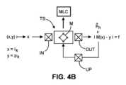
図4Aは、(ライブ)入力イメージIkから撮像ジオメトリ変化ベクトルpk、又はそのようなイメージのシーケンスを推測するために適切なCNN構成の例示的な実施形態である。モデルは、好ましくは、1つ又は複数の隠れ層を含むディープニューラルネットワークである。層Liは、入力層と出力層との間に配置されているような隠れ層である。ネットワークMは、複数の畳み込みフィルタ層Liからなり、いくつか又はそれぞれが1つ又は多数の畳み込みフィルタカーネルを採用する。畳み込みフィルタ層のうちのいくつか又はそれぞれの後に、活性化層及びいくつかの実施形態では、プーリング層(図示せず)が続く。任意選択で、バッチ正規化及びドロップアウト層の一方又は両方もある。さらに任意選択で、さらに1つ又は複数の十分に接続された層がある。上述の一連の層は、(好ましくは正規化された)ベクトルpkの推定値を生成する回帰層で終端する。分類出力は、いくつかの実施形態では代わりに想定される。 FIG. 4A is an exemplary embodiment of a CNN configuration suitable for inferring an imaging geometry change vector pk from a (live) input image Ik, or a sequence of such images. The model is preferably a deep neural network containing one or more hidden layers. Layer Li is a hidden layer such that it is placed between the input and output layers. The network M consists of multiple convolution filter layers Li, some or each of which employs one or many convolution filter kernels. Some or each of the convolution filter layers are followed by an activation layer and in some embodiments a pooling layer (not shown). Optionally, there are also batch normalization and/or dropout layers. Further optionally, there are one or more fully connected layers. The series of layers described above ends with a regression layer that produces an estimate of the (preferably normalized) vector pk. A classification output is instead envisioned in some embodiments.
活性化層は、一層からの出力値が修正されて入力として次の層へ提供される(典型的には非線状の)関数を決定する。プーリング層は、一層の複数の要素からの出力を組み合わせて、次の層の単一の要素への入力として供給する。組み合わされた、それぞれが畳み込みの活性化及びプーリングの各層は、データを非線状に処理し、その次元を変え、次の層へ通過させるように機能する。畳み込み層のそれぞれのパラメータは、トレーニング位相で「学習」(最適化)される。各畳み込み層のパラメータの数は、畳み込みカーネルのサイズ、カーネルの数、及び所与の層で処理されたイメージ上を移動するときのステップサイズ「ストライド」に依存する。十分に接続された層のパラメータの数は、前の層及び現在の層の要素における数によって決まる。 The activation layer determines the (typically non-linear) function in which the output values from one layer are modified and provided as input to the next layer. A pooling layer combines the outputs from multiple elements in one layer and feeds them as input to a single element in the next layer. The combined convolutional activation and pooling layers respectively serve to process the data non-linearly, changing its dimension and passing it through to the next layer. Each parameter of a convolutional layer is "learned" (optimized) in a training phase. The number of parameters in each convolutional layer depends on the size of the convolution kernel, the number of kernels, and the step size "stride" when moving over the image processed by a given layer. The number of fully connected layer parameters depends on the numbers in the previous and current layer elements.
任意選択で、追加の入力パラメータakはモデル内へ組み込まれてモデルの精度及び一般化能力を改善する。これらの非イメージパラメータは、通常は範疇の、まばらに表されたデータであるが、低次元の埋め込み(例えば、ワンホット符号化)によって表されることができる。例えば、そのような埋め込みは、1つ又は複数の十分に接続された層によって処理されることができ、次いで、1つ又は複数の十分に接続された層からの出力を特徴マップの空間次元にわたって傾けることによって、任意の中間特徴マップ(層)へ点別に追加又は連結される。 Optionally, additional input parameters ak are incorporated into the model to improve the accuracy and generalizability of the model. These non-image parameters are usually categorical, sparsely represented data, but can be represented by low-dimensional embeddings (eg, one-hot encoding). For example, such embeddings can be processed by one or more well-connected layers, then output from one or more well-connected layers across the spatial dimensions of the feature map. Tilting adds or connects pointwise to any intermediate feature map (layer).
一旦トレーニングされると、展開中に、現在のイメージジオメトリIk[又は(Ik,ak)]で取得された所与のROI_1で現在のライブ入力イメージなどの実際のデータが入力層INLへ適用される。入力層INLから、イメージデータIkは、隠れ層L1~LNによって表されるフィルタの適用によって伝播する。層L1~LNの数は、2、3又は数十程度ではるかに多い(例えば、20~50又はその他)。イメージデータIkは、伝搬中に変換され、その後、特徴ベクトル層OUTLとして出現する。コンテキストデータakは、1つ又は複数の十分に接続された層を含むモデル(図示せず)の異なるストランドを介して伝搬される。これら2つのストランドの出力、イメージデータIkを処理するストランドL1~LN及び(おそらく非イメージ)コンテキストデータakを処理するストランドが、埋め込みをさらに参照して以下でより詳細に説明するようにマージされる。Once trained, real data such as the current live input image at a given ROI_1 acquired with the current image geometry Ik[or (Ik,ak)] is applied to the input layer INL during deployment. . From the input layer INL, the image data Ik are propagated by application of the filters represented by the hidden layers L1-LN . The number of layers L1 -LN may be in the order of 2, 3 or even tens of thousands (eg 20-50 or others). The image data Ik are transformed during propagation and then appear as a feature vector layer OUTL. The context data ak is propagated through different strands of a model (not shown) containing one or more well-connected layers. The output of these two strands, the strands L1-LN processing the image data Ik and the strand processing the (possibly non-image) context data ak, are merged as described in more detail below with further reference to embedding. be.
特徴ベクトル層OUTLは、入力イメージIkの低次元1D表現と考えることができる。特徴ベクトルOUTLの後には、タスクに応じて、活性化関数(例えば、線状、シグモイド、ソフトマックス、正接双曲線のいずれか1つ又は複数)を有する十分に接続された層又は畳み込み層などの、単一又は複数のタスク固有層(図示せず)が続く。タスクは回帰又は分類である。1つ又は複数のタスク固有層は、特徴ベクトル層OUTLへ適用されて撮像ジオメトリ変化仕様を推定し、実施形態では、回帰する。撮像ジオメトリ変化仕様は、所望の最終出力
1つ、複数、又は全ての隠れ層Liは畳み込み層であり、それらの動作はフィルタに関して定義されることができる。モデルMで使用される畳み込み層は、十分に接続された層と区別されるべきである。畳み込み層では、各ノードは前の層の(プールされた)ノードのサブセットへのみ接続される。フォローアップ層のノードは、前の層からのノードのサブ選択に基づいてフィルタ操作を形成することによって計算される。フォローアップ層の異なるノードに対して、前の層の異なるサブセットが、好ましくは同じフィルタで処理される。フィルタは、行列に配置可能な数の集合値fijである。いくつかの実施形態では、フィルタ操作は、前の層のノードである積fij・njk,njkの和を形成することを含む。したがって、この積和操作は、フィルタマスクが行列データ上で摺動される伝統的な畳み込み又はフィルタ操作と同種である。一般に、層は行列として実装される。層を介したデータの伝播を実施するフィルタ操作は、行列操作として実施され、好ましくはGPU、又はマルチコア設計を有するプロセッサなどの並列処理が可能な他のプロセッサで実行される。十分に接続された層では、前の層の各ノードは、学習可能な活性化重みを使用して現在の層のノードへ接続される。One, several or all hidden layers Li are convolutional layers and their behavior can be defined in terms of filters. The convolutional layers used in model M should be distinguished from well-connected layers. In a convolutional layer, each node is connected only to a subset of the (pooled) nodes of the previous layer. Follow-up layer nodes are computed by forming a filter operation based on a sub-selection of nodes from the previous layer. For different nodes in the follow-up layer, different subsets of the previous layer are preferably processed with the same filter. A filter is a set of values fij that can be arranged in a matrix. In some embodiments, the filtering operation includes forming the sum of the products fij ·njk , njk that are the nodes of the previous layers. Therefore, this multiply-accumulate operation is akin to a traditional convolution or filtering operation in which a filter mask is slid over the matrix data. Generally, layers are implemented as matrices. Filter operations that implement data propagation through layers are implemented as matrix operations and are preferably executed on a GPU or other processor capable of parallel processing, such as a processor with a multi-core design. In a well-connected layer, each node in the previous layer is connected to a node in the current layer using learnable activation weights.
上述のように、十分に接続された層も、患者の生物学的特性などの非イメージデータakの処理のために本明細書で想定される。十分に接続された層は、そのような十分に接続された層の1つ又は2つ以上が順番に配置され、それを介して非イメージデータakが通過する処理層の別のストランド(図示せず)を形成することが想定される。任意選択で、このデータはまた、イメージの処理のために上述した畳み込み層とは別個且つ異なる畳み込み層を通過する。この非イメージデータ処理ストランドの出力は、次いで、図4Aに示されるイメージ処理ストランド内へ供給されることができる。具体的には、非撮像データに対する十分に接続された層の最後の出力が、モデルのCNN分岐において隠れ層の1つへ連結されて、非イメージデータをイメージデータとマージさせることができる。このようにして、出力、すなわち、撮像ジオメトリ変化は、イメージデータにおける空間データだけでなく、患者に関する、より多くの詳細を提供するコンテキストデータも考慮し、このようにモデルを異なるタイプの患者に対してよりよく一般化する。 As noted above, well-connected layers are also envisioned herein for processing non-image data ak, such as patient biological characteristics. A well-connected layer is another strand of processing layers (not shown) in which one or more of such well-connected layers are arranged in sequence and through which the non-image data ak passes. is assumed to form Optionally, this data also passes through a convolutional layer separate and distinct from the convolutional layers described above for processing the image. The output of this non-image data processing strand can then be fed into the image processing strand shown in FIG. 4A. Specifically, the last output of a well-connected layer for non-imaging data can be concatenated into one of the hidden layers in the CNN branch of the model to allow the non-image data to merge with the image data. In this way, the output, ie the imaging geometry change, takes into account not only spatial data in the image data, but also contextual data that provides more detail about the patient, thus adapting the model to different types of patients. generalize better.
前述のように、ワンホット符号化などの埋め込みは、範疇の疎データをベクトルとして表すために使用されることができる。非イメージデータ処理ストランドは、十分に接続された層及び畳み込み層の組み合わせを含んでもよい。また、図2に示すようなイメージデータ処理ストランドは、特に非イメージデータakが共同で処理され、拡張データ(Ik,ak,)として各層を通過する場合、1つ又は複数の十分に接続された層のシーケンスを含んでもよい。畳み込み層及び十分に接続された層に加えて、いずれか一方又は両方のストランドが、いずれか1つ又は複数のプーリング層、活性化層、ドロップアウト層を任意の組み合わせでさらに含んでもよい。さらに、畳み込み層に対する逆の操作の近似を表すと考えられるデコンボリューション層が存在する可能性がある。各層で生成されるノードの数は寸法で変化するので、出力層のサイズ(行及び列の数)及び/又は深さが拡大又は縮小する可能性がある。畳み込み層の出力の寸法は、一般に、フィルタが各操作に対して摺動して通過するノードの数を表す「ストライド」に応じて、入力の寸法以下である。したがって、ダウンサンプリングが生じる。アップサンプリングもデコンボリューション層で想定される。一部のアーキテクチャには、アップサンプリング層の次にダウンサンプリング、又はその逆のそれぞれを1又は複数回実行することが含まれる。一般的には、図4Aのアーキテクチャは、ネットワークが入力イメージIkを下方にベクトル
ここでトレーニング位相又はプロセスを参照すると、これは、図4Bに示すトレーニングシステムTSによって実施可能である。トレーニングは、適切なトレーニングデータに基づいている。トレーニングデータは、実際の画像を取得することによって、又はシミュレートされたX線イメージを得ることによって得られることができ、両方とも本明細書ではIkと表記される。実際のX線画像は、PACSなどの患者記録から又は他のイメージリポジトリから履歴イメージデータとして検索される。 Referring now to the training phase or process, this can be implemented by the training system TS shown in FIG. 4B. Training is based on good training data. Training data can be obtained by acquiring real images or by acquiring simulated X-ray images, both denoted Ik herein. Actual x-ray images are retrieved from patient records such as PACS or from other image repositories as historical image data.
より詳細には、トレーニングは、正規化された座標を使用してモデルランドマークのうちの1つ又は複数に対するイメージの位置を記述する要素{pk,1,...pkN}を含む「グラウンドトゥルース」座標ベクトルpkと対にされた、実際の又はシミュレートされたX線イメージIk(k∈1...K)の取得を含む。要素Nの数は、モデル座標空間(2D又は3D)の次元、モデルにおけるランドマークの数、及びランドマーク位置のパラメータ化に依存する。典型的には、Nは2から30の間の範囲であり、Kは大きく(例えば、K>>30)、イメージIkは大きく且つ可変の対象集団から選択される。また、グランドトゥルースデータpkは、ROIポーズ座標に関して表現されず、代わりに、テーブル並進、Cアームガントリの回転/角形成、又は関連する撮像ジオメトリ構成要素の任意の他のポーズ仕様に関して、イメージジオメトリ(変化)座標として直接提供される。撮像ジオメトリpkデータは、ROIのうちの所与の1つに対する撮像ジオメトリ変化として、又は「ゼロ」角度/回転、位置/傾き「ゼロ」でのテーブルなどの参照撮像ジオメトリを与えられた各ROIの絶対撮像ジオメトリパラメータとして表現される。More specifically, the training uses normalized coordinates to create elements {pk, 1, . . . pkN }, a real or simulated X-ray image Ik (kε1...K) paired with a “ground truth” coordinate vector pk containing pk N }. The number of elements N depends on the dimensionality of the model coordinate space (2D or 3D), the number of landmarks in the model, and the parameterization of the landmark positions. Typically, N ranges between 2 and 30, K is large (eg, K>>30), and images Ik are selected from a large and variable subject population. Also, the ground truth data pk are not expressed in terms of ROI pose coordinates, but instead in terms of table translation, C-arm gantry rotation/angulation, or any other pose specification of the relevant imaging geometry components, image geometry ( change) provided directly as coordinates. The imaging geometry pk data is either as imaging geometry changes for a given one of the ROIs, or for each ROI given a reference imaging geometry such as a table at "zero" angle/rotation, position/tilt "zero". Expressed as absolute imaging geometry parameters.
対{Ik,pk}は、トレーニングプロセスで使用され、このプロセスにおいて、イメージIkが畳み込みニューラルネットワーク(CNN)への入力として提供され、ネットワークパラメータが出力として座標ベクトルpkを推測するように最適化される。任意選択で、イメージは、入力としての追加の患者固有パラメータベクトルak(例えば、身長、体重、年齢、性別、民族性、BMI、解剖学的異常、移植されたデバイスなど)と対にすることができる。このタスクに対する1つの適切なCNN構成は、図4Aに示すものであるが、他のアーキテクチャも本明細書で想定され、支援ベクトル機械(SVM)、決定木、ランダムフォレストその他などのNN以外のモデルも想定される。 The pair {Ik, pk} is used in a training process in which the image Ik is provided as input to a convolutional neural network (CNN) and the network parameters are optimized to infer the coordinate vector pk as output. be. Optionally, the image can be paired with additional patient-specific parameter vectors ak as inputs (e.g., height, weight, age, gender, ethnicity, BMI, anatomical abnormalities, implanted devices, etc.). can. One suitable CNN configuration for this task is that shown in FIG. 4A, but other architectures are also envisioned herein, and models other than NNs such as support vector machines (SVMs), decision trees, random forests, etc. is also assumed.
図4Bを引き続きかつより詳細に参照すると、コンピュータ化されたトレーニングシステムTSは、トレーニングデータ(X,Y)iに基づいて機械学習モデルMをトレーニングするために使用される。「X」は適切なイメージIkを表す一方で、「Y」は関連した撮像ジオメトリ変化pcを表し、本明細書ではXの対象物とも称され、おそらくイメージ設定データEPXによって拡張される。With continued and more detailed reference to FIG. 4B, a computerized training system TS is used to train the machine learning model M based on the training data (X,Y)i . "X" represents the pertinent image Ik, while "Y" represents the associated imaging geometry change pc, also referred to herein as the object of X, possibly augmented by image settings data EPX.
トレーニングデータの対は、人間の専門家による手動注釈演習で得ることができる。あるいは且つ好ましくは、注釈は、検索且つ自動化される。所与のトレーニングイメージに関連する撮像ジオメトリデータ及び/又はEPXデータは、DICOMヘッダデータなどのメタデータから組み立てられてもよく、又はデータベースに保持されている患者記録から検索されてもよい。適切にプログラムされたスクリプト作成ツールは、各イメージX=Ikについて関連した撮像ジオメトリ変化Y=pkを見出すことを遂行するために使用される。 Training data pairs can be obtained in manual annotation exercises by human experts. Alternatively and preferably, annotations are retrieved and automated. The imaging geometry data and/or EPX data associated with a given training image may be assembled from metadata such as DICOM header data or retrieved from patient records held in a database. A suitably programmed scripting tool is used to accomplish finding the associated imaging geometry change Y=pk for each image X=Ik.
したがって、トレーニングデータは、特に、本明細書で主に想定されるような教師あり学習スキームのための対iに編成される。しかしながら、教師なし学習スキームは本明細書では除外されないことに留意されたい。 The training data are therefore organized into pairs i, specifically for supervised learning schemes as primarily assumed herein. Note, however, that unsupervised learning schemes are not excluded here.
図4Aに示すCNNネットワーク、又はイメージデータIkを処理するためのCNNストランドと非イメージデータakを処理するための十分に接続された層ストランドとを備えるハイブリッドネットワークのような、機械学習モデルMが選ばれ、重みは、いくつかの初期、おそらくランダム又は均一なデータで事前入力される。例えば、全てのノードの重みは全て「1の」又は他の数によって設定される。 A machine learning model M is chosen, such as the CNN network shown in FIG. 4A, or a hybrid network comprising CNN strands for processing image data Ik and well-connected layer strands for processing non-image data ak. The weights are prepopulated with some initial, possibly random or uniform data. For example, all node weights are set to all "ones" or some other number.
モデルMの重みθはパラメータ化Mθを表し、トレーニングデータ(Xi、Yi)対に基づいてパラメータθを最適化し、したがって適応させることは、トレーニングシステムTSの目的である。言い換えると、学習は、コスト関数が最小化される最適化スキームとして数学的に形式化されることができるが、代わりに、効用関数を最大化する二重定式化が使用されてもよい。The weights θ of the model M represent the parameterization Mθ and it is the goal of the training system TS to optimize and thus adapt the parameters θ based on the training data (Xi , Yi ) pairs. In other words, learning can be mathematically formalized as an optimization scheme in which the cost function is minimized, but alternatively a dual formulation that maximizes the utility function may be used.
今のところ、コスト関数fのパラダイムを仮定すると、これは凝集残留物、すなわち、モデルMによって推定されたデータとトレーニングデータ対iの一部又は全てに従う対象物との間に生じた誤差を測定する。
最小値の引数θf=Σi||Mθ(Xi)-Yi|| (3)For now, assuming a paradigm of cost function f, this measures the aggregate residual, i.e., the error generated between the data estimated by model M and the subject following some or all of the training data pairs i. do.
Minimum argumentθ f=Σi ||Mθ (Xi )−Yi || (3)
より具体的には、トレーニング対のイメージデータXは、初期化されたネットワークMを介して伝搬される。最初の対「i」のXは入力INで受信され、モデルを通過し、次いで、出力トレーニングデータMθ(X)として出力OUTで受信される。適切な尺度||・||は、pノルム、自乗差その他などを使用して、実際の出力Mθ(X)と所望の出力Yとの差を測定する。More specifically, training pairs of image data X are propagated through an initialized network M . The first pair 'i' of X is received at input IN, passed through the model, and then received at output OUT as output training data Mθ (X). A suitable measure ||·|| measures the difference between the actual output Mθ (X) and the desired output Y using p-norm, squared difference, and so on.
出力トレーニングデータM(X)は、入力トレーニングイメージデータXを与えられた提案された撮像ジオメトリ変化の推定値である。一般に、この出力M(X)と、現在考えられている対の関連した対象物Yとの間には誤差がある。次に、後方/前方伝搬又は他の勾配ベースの方法などの最適化スキームを使用して、モデルMθのパラメータθを適応させ、考慮された対(X,Y)iの残留物を減少させる。The output training data M(X) is an estimate of the proposed imaging geometry change given the input training image data X. In general, there is an error between this output M(X) and the associated object Y of the pair currently considered. Optimization schemes such as backward/forward propagation or other gradient-based methods are then used to adapt the parameters θ of the model Mθ to reduce the residual of the considered pair (X, Y)i .
モデルのパラメータθが、使用された最適化スキームに基づいて更新される第1の、内部のループにおける1つ又は複数の反復の後、トレーニングシステムTSは、次のトレーニングデータ対Xi+1、Yi+1がそれに応じて処理される第2の、外部のループに入る。この内部ループは、順方向/逆伝搬アルゴリズムにおける1つ又は複数の前方及び後方パスによって実施される。しかしながら、このとき残留物を適応させながら、適応される現在の対に対する個々の残留物だけでなく、この時点までに考慮された全てのトレーニング対の凝集且つ合計された残留物が、オブジェクト関数を改善するために必要な場合に適応される。凝集残留物は、オブジェクト関数fを、各対に対して考慮される残留物の一部又は全ての等式(3)におけるように自乗和(又は他の代数の組み合わせ)として構成することによって形成することができる。After one or more iterations in the first, inner loop, in which the model parameters θ are updated based on the optimization scheme used, the training system TS uses the following training data pair Xi+1 , Yi+1 enters a second, outer loop where is processed accordingly. This inner loop is implemented by one or more forward and backward passes in the forward/backward propagation algorithm. However, while adapting the residuals this time, not only the individual residuals for the current pair being adapted, but also the aggregated and summed residuals of all training pairs considered up to this point, yield the object function Adapted where necessary for improvement. Aggregate residues are formed by constructing the object function f as a sum of squares (or other algebraic combination) as in equation (3) of some or all of the residues considered for each pair. can do.
図4Bに示すような一般化されたトレーニングシステムが、全ての学習スキーム、特に教師ありスキームに対して考慮されることができる。また、位相空間で適切なクラスタリングを行う教師なし学習スキームは、拡張されていてもいなくても、想定される。 A generalized training system as shown in FIG. 4B can be considered for all learning schemes, especially supervised schemes. Also, unsupervised learning schemes with good clustering in topological space, whether extended or not, are envisioned.
ここで図5Aのフローチャートを参照して、イメージベースのナビゲーションを支援する方法をより詳細に説明する。本方法は、上述したイメージ処理システムSYSの操作の根底にあると理解される。しかしながら、図5Aで説明した方法ステップが、図1~図4を参照して上述したようなイメージ処理システムSYSのアーキテクチャへ必ずしも結びついていないことが理解される。より詳細には、以下に記載する方法は、それ自体が教示として理解される。図5Aのフローチャートは、機械学習モデルが、例えば、図4で上述したように、十分にトレーニングされたと仮定して説明する。 A method for supporting image-based navigation will now be described in more detail with reference to the flowchart of FIG. 5A. The method is understood to underlie the operation of the image processing system SYS described above. However, it will be appreciated that the method steps illustrated in FIG. 5A are not necessarily tied to the architecture of the image processing system SYS as described above with reference to FIGS. 1-4. More particularly, the methods described below are to be understood as teachings per se. The flow chart of FIG. 5A is described assuming that the machine learning model has been fully trained, eg, as described above in FIG.
ステップS510で、患者が、X線撮像テーブルTB上に位置決めされる。ステップS520で、第1の/次のX線ライブイメージが、第1のテーブル位置などの第1の撮像ジオメトリIG1で、第1のROI_1において得られ且つ受信される。 At step S510, the patient is positioned on the X-ray imaging table TB. At step S520, a first/next live X-ray image is obtained and received at a first ROI_1 at a first imaging geometry IG1, such as a first table position.
ステップS530で、図4Aで上述したCNNなどの予めトレーニングされた機械学習構成要素を使用して、第1の/次のX線イメージは処理されて、ROI_1=Rの現在の撮像ジオメトリから、1つ又は複数の他のROI_2=i又はモデルランドマーク(複数可)に対する新しい撮像ジオメトリIG2への必要とされる撮像ジオメトリ変化(相対的なテーブルの動きなど)を推測する。この撮像ジオメトリ変化は、2つのROIsであるROI_1=R及びROI_2=iの関数であるジオメトリ変換TR,iによって表されてもよい。At step S530, using a pre-trained machine learning component such as the CNN described above in FIG. 4A, the first/next X-ray image is processed to obtain 1 Infer the required imaging geometry changes (relative table motion, etc.) to the new imaging geometry IG2 relative to one or more other ROI_2=i or model landmark(s). This imaging geometry change may be represented by a geometry transformation TR ,i that is a function of the two ROIs ROI_1=R and ROI_2=i.
ステップS540で、必要とされる撮像ジオメトリ変化は、例えば、1つ又は複数の撮像ジオメトリ構成要素に対して角度値、並進値、又はその両方を指定する座標ベクトルpkの形態でさらなる処理のために利用可能にされる。 In step S540, the required imaging geometry changes are obtained for further processing, e.g., in the form of coordinate vectors pk specifying angular values, translational values, or both, for one or more imaging geometry components. made available.
ステップS550では、CNNによって推測されたランドマークのいずれかに対応する第2の(対象物)ROIは、ユーザによって選択される又は使用される撮像プロトコルの仕様などのコンテキストデータに基づいてMLCによって自動的に決定される、のいずれかである。この第2のROIであるROI_2の選択ステップS550は、ステップS530の前に交互に行うことができる。 In step S550, a second (object) ROI corresponding to any of the landmarks inferred by the CNN is automatically selected by the MLC based on context data such as the specification of the imaging protocol selected or used by the user. either This second ROI, ROI_2 selection step S550 can alternately be performed before step S530.
任意のステップS560では、MLC出力と現在のテーブル位置とに基づいて、次のイメージを対象物ROI上にセンタリングするために必要な相対的なテーブルの動きが計算される。このステップは、MLC出力がIGを明示的に表すのではなく、むしろ新しい撮像ジオメトリIG2を代わりに表す場合に必要とされる。 In optional step S560, the relative table motion required to center the next image on the object ROI is calculated based on the MLC output and the current table position. This step is required if the MLC output does not explicitly represent IG, but rather represents the new imaging geometry IG2 instead.
ステップS570では、達成された撮像ジオメトリ変化(対象物に対するテーブルの動きなど)は、自動的若しくは半自動的に達成される、又はそうでなければ促進される。実施形態は、自動的な動き、又は、例えば、触覚補助若しくは他の形態のフィードバックを伴う視覚や音声ガイダンス若しくは機械的フィードバックなどの補助規定を含む。任意のステップS580では、任意の撮像設定(例えば、EPX)は、例えば、事前定義されたルックアップ表によって指定された又はMLCによって学習されたように、対象物ROI_2に対して自動的に更新される。 In step S570, achieved imaging geometry changes (such as table movement relative to the object) are automatically or semi-automatically achieved or otherwise facilitated. Embodiments include automatic movement or provision of assistance, such as visual or audio guidance or mechanical feedback, for example, with tactile assistance or other forms of feedback. In optional step S580, any imaging settings (e.g., EPX) are automatically updated for object ROI_2, e.g., as specified by a predefined lookup table or learned by the MLC. be.
撮像ジオメトリ変化がステップS530で全ての関連する撮像ジオメトリ構成要素に対して計算されていない場合がある。例えば、ステップS530では、必要とされるテーブルの動き及び/又はCアーム並進のみが計算され、Cアームの回転/角形成は計算されなかった。この場合、次に、Cアーム角度が対象物ROIのROI_2で予想される次の撮像のために必要に応じて調整される任意の追加のステップがあってもよい。これは、ユーザによるものであってもよい。代替としても、一部の撮像ジオメトリ変化は、計算されている一方で、Xアームの回転/角形成などは自動的には達成されない。調整は、依然として、ユーザインタフェースIG-UIを介してユーザによって手動で行われるが、システムは、例えば、システムSYSの様々な半自動の実施形態において上述したような触覚的、視覚的(ビデオ又はイメージ)又は他の信号/刺激を介して、機械援助を提供する。 The imaging geometry changes may not have been calculated for all relevant imaging geometry components in step S530. For example, in step S530, only the required table motion and/or C-arm translation was calculated, not C-arm rotation/angulation. In this case, there may then be an optional additional step in which the C-arm angle is adjusted as needed for the next imaging expected at ROI_2 of the object ROI. This may be user-initiated. Alternatively, some imaging geometry changes are calculated while X-arm rotation/angulation, etc. are not automatically accomplished. Adjustments are still made manually by the user via the user interface IG-UI, but the system uses, for example, tactile, visual (video or image) adjustments as described above in various semi-automatic embodiments of the system SYS. or provide mechanical assistance via other signals/stimuli.
ここで図5Bのフローチャートを参照すると、これは、特に図4A及び図4Bで上述したように機械学習モデルMLCをトレーニングするためのコンピュータ化された方法を示す。ステップS610では、トレーニングデータは、特定の関心領域及び1つ又は複数の他の関心領域に対する関連したジオメトリ変化を表す画像を含む対の形態で受信される。 Reference is now made to the flow chart of FIG. 5B, which illustrates a computerized method for training a machine learning model MLC, particularly as described above in FIGS. 4A and 4B. In step S610, training data is received in pairs containing images representing associated geometric changes for a particular region of interest and one or more other regions of interest.
ステップS620では、画像、及び任意選択でイメージ及び/又はイメージ設定で表される患者の生体特性を含む非イメージデータが、初期化された機械学習モデルMへ適用されて出力を生成する。 In step S620, the images and non-image data, including patient biometrics optionally represented by images and/or image settings, are applied to the initialized machine learning model M to generate an output.
関連した撮像ジオメトリ変化を伴う出力の偏差は、コスト関数fによって定量化される。モデルの1つ又は複数のパラメータは、ステップS630で、内部ループにおける1つ又は複数の反復において、例えば、残留物を減少させるために適応される。 Deviations in output with associated imaging geometry changes are quantified by a cost function f. One or more parameters of the model are adapted at step S630 in one or more iterations in the inner loop, eg, to reduce residuals.
次に、トレーニング方法はステップS610へ戻り、ここで、次の対のトレーニングデータが入力され、外部ループに入る。ステップS620では、その時点までに考慮された全ての対の凝集残留物が最小化される。 The training method then returns to step S610 where the next pair of training data is input and the outer loop is entered. In step S620, all pairs of aggregate residues considered up to that point are minimized.
より一般的には、モデルMのパラメータは、コスト関数又は効用関数のいずれかであるオブジェクト関数を改善するために調整される。
さらなる実施形態More generally, the parameters of model M are adjusted to improve an object function, either a cost function or a utility function.
Further embodiments
撮像ジオメトリ、及び撮像ジオメトリ変化は、位相空間内の点を表すベクトルpkを参照して上述した。この空間は、一般に、高次元空間であり、考慮される撮像装置によって与えられる自由度及び/又はそれが使用する撮像ジオメトリ構成要素の数に依存する。 The imaging geometry and imaging geometry changes are described above with reference to a vector pk representing a point in phase space. This space is generally a high-dimensional space and depends on the degrees of freedom provided by the considered imaging device and/or the number of imaging geometry components it uses.
機械学習モデルMは、位相空間の全てにわたる撮像ジオメトリ全体を説明するようにトレーニングすることができる一方で、推定を位相空間の特定の部分空間へ制限することが望ましいことは時折ある。部分空間の外側の他の撮像ジオメトリパラメータは推定されない。関連した撮像ジオメトリ構成要素は、ユーザによって手動で調整される。より詳細には、Cアーム又はUアームイメージャに関係する実施形態では、関心ジオメトリ変化は、その縁辺に沿った空間次元X、Yのいずれか一方又は両方におけるテーブルの動き/傾きのみに限定される。また、角度値、すなわち、関心のあるCアームの回転及び/又は角形成の変化でもある。ここでも、同じ原理が他の撮像様式へ適用されることができるので、本明細書に開示される原理は、必ずしもX線又はCアームベースのイメージャに結びついているわけではない。 While a machine learning model M can be trained to describe the entire imaging geometry over all of phase space, it is sometimes desirable to restrict the estimation to a particular subspace of phase space. Other imaging geometry parameters outside the subspace are not estimated. Associated imaging geometry components are manually adjusted by the user. More particularly, in embodiments involving C-arm or U-arm imagers, the geometric changes of interest are limited only to movement/tilt of the table in either or both of the spatial dimensions X, Y along its edges. . It is also the angular value, ie the change in rotation and/or angulation of the C-arm of interest. Again, the principles disclosed herein are not necessarily tied to X-ray or C-arm based imagers, as the same principles can be applied to other imaging modalities.
撮像ジオメトリ変化の純粋に空間的な態様に加えて、位相空間の次元は、位相空間の点に隣接する撮像設定EPXパラメータによって拡張することができる。機械学習モデルは、次いで、この拡張された一般化位相空間で操作される。撮像設定EPXは、同様に、ある設定を表す各エントリの1つ又は複数のベクトルによって記載することができる。撮像設定は、X線ビーム若しくは超音波ビームのエネルギーなどの問い合わせ撮像信号の非空間特性、又は何らかの考慮されている撮像様式に関する。 In addition to the purely spatial aspect of imaging geometry variation, the dimensionality of phase space can be extended by imaging setup EPX parameters adjacent to points in phase space. A machine learning model is then operated on this extended generalized topological space. An imaging setting EPX can similarly be described by one or more vectors with each entry representing a setting. Imaging settings relate to non-spatial properties of the interrogating imaging signal, such as the energy of an X-ray beam or an ultrasound beam, or any imaging modality under consideration.
特に、X線撮像を参照すると、イメージ設定EXPは、特に管電圧及び/又は管電流、又はX線管の他の一般的な設定を含む。本明細書で想定される他のイメージ設定EPXには、フィルタリング及びノイズ除去などのフレームレート設定及びイメージ処理パラメータ、デジタル差分血管造影法(DSA)又は単一露光撮像などの動作のモードが含まれる。 In particular, with reference to X-ray imaging, the image settings EXP include, among other things, tube voltage and/or tube current, or other general settings of the X-ray tube. Other image settings EPX contemplated herein include frame rate settings and image processing parameters such as filtering and denoising, modes of operation such as digital differential angiography (DSA) or single exposure imaging. .
学習に撮像設定を含めることで、上述の処理システムは、撮像ジオメトリ変化だけではなく撮像設定EPXへの変化もさらに推定することができる。しかしながら、他の実施形態では、設定はユーザによって手動で調整され、十分又は部分的な撮像ジオメトリのみが、推定され、所望される場合は、自動的に達成される。 By including the imaging settings in the learning, the processing system described above can further infer changes to the imaging settings EPX as well as changes in the imaging geometry. However, in other embodiments, the settings are manually adjusted by the user, and only full or partial imaging geometry is estimated and, if desired, automatically achieved.
上述したように、全てのランドマーク又はROIsは、1つのニューラルネットワークCNNによる単一の機械学習構成要素によって考慮することができる。推定された撮像ジオメトリパラメータベクトル
さらに又は代わりに、異なる現在のイメージジオメトリに専用の複数の異なる機械学習モデルが提供されてもよい。例えば、1つのモデルは、前後撮像方向にガントリで撮像されたROIsの全て又はサブセットを扱うために使用される一方で、別のモデルは、横方向の視線方向に撮像されたROIsを扱うために使用される。 Additionally or alternatively, multiple different machine learning models dedicated to different current image geometries may be provided. For example, one model may be used to handle all or a subset of ROIs imaged on the gantry in the anterior-posterior viewing direction, while another model may be used to handle ROIs imaged in the lateral viewing direction. used.
さらに又は代わりに、実施形態では、複数の機械学習モデルは、撮像ジオメトリ自体の態様によってパラメータ化されてもよい。言い換えると、ある部分空間及び位相空間に対する撮像ジオメトリ変化は、異なる位相空間における撮像ジオメトリパラメータの値によってパラメータ化されていると考えられる。より具体的には、複数の値が、例えば、異なるCアーム角形成又は回転によりイメージ上でパラメータ化されたテーブルの動きを予測するために使用されてもよい。これらのモデルでは、ユーザはまずCアームのそれぞれの角形成又は回転を選び、次に、対応する機械学習モデルを選択してから、空間次元X、Yのいずれか一方又は両方において必要とされるテーブルの動きを予測する。 Additionally or alternatively, in embodiments, the multiple machine learning models may be parameterized by aspects of the imaging geometry itself. In other words, the imaging geometry changes for one subspace and phase space are considered parameterized by the values of the imaging geometry parameters in different phase spaces. More specifically, multiple values may be used to predict motion of a parameterized table over an image with, for example, different C-arm angulations or rotations. In these models, the user first selects the respective angulation or rotation of the C-arm, then selects the corresponding machine learning model, then the required in either or both of the spatial dimensions X, Y Predict table movement.
推定が制限された別の、より単純化された実施形態では、MLC(複数可)は、仮想の図2のモデルにおいてランドマーク位置のサブセクトに関して、撮像ジオメトリ変化のサブセットのみを推定する。モデルにおける追加のランドマーク位置は、次いで、MLC(s)によって予測される近くのランドマークの、例えば、補間又は外挿によって、より低い計算コストで得られる。補間又は外挿プロセスは、予測されたランドマーク位置を対応するモデルランドマークで点別登録によって駆動されることができる。 In another, more simplified embodiment with limited estimation, the MLC(s) estimate only a subset of the imaging geometry changes for a subset of landmark positions in the hypothetical FIG. 2 model. Additional landmark positions in the model are then obtained at lower computational cost, eg, by interpolation or extrapolation of nearby landmarks predicted by MLC(s). The interpolation or extrapolation process can be driven by pointwise registration of predicted landmark positions with corresponding model landmarks.
さらに、EPX設定などのイメージ設定に対して、自動的に、又は適切な入力ユーザインタフェースを介したユーザによる確認に基づいて調整することができる。この調整は、現在又は次の撮像ジオメトリに対する患者のポーズ推定値に基づいてもよい。 Additionally, image settings, such as EPX settings, can be adjusted automatically or upon confirmation by the user via a suitable input user interface. This adjustment may be based on patient pose estimates for the current or next imaging geometry.
上述の実施形態では、現在のROIが与えられ、次のROIを選ぶのはユーザであるが、想定される、より洗練された実施形態では、現在使用されている撮像プロトコルに基づいて現在の関心領域が与えられ、次の関心領域とともに予測するのはナビゲーションSYS自体である。言い換えると、撮像の変化が予測されるだけではなく、次にどの関心領域が考慮される可能性があるかも予測される。ユーザは、このROI推定値を上書きするか、又は入力ユーザインタフェースを介して確認することができ、それに応じて、それぞれの撮像ジオメトリ変化が推定される。 While in the above embodiment the current ROI is given and it is the user who chooses the next ROI, envisioned more sophisticated embodiments may Given a region, it is the navigation SYS itself that predicts with the next region of interest. In other words, not only are imaging changes predicted, but also which regions of interest may be considered next. The user can override this ROI estimate or confirm it via an input user interface, and the respective imaging geometry change is estimated accordingly.
上記の全てにおいて、撮像ジオメトリ変化の推定値及び次の関心領域を使用して、それぞれのアクチュエータを制御することによって実際の撮像ジオメトリ変化を達成することができる。撮像ジオメトリ変化は、いかなるユーザの関与もなく十分に自動的に達成されることができる。あるいは且つ好ましくは、グラフィカル又は他のユーザインタフェースにより、ユーザは推定値を確認することができ、その後にのみ、撮像ジオメトリ変化がアクチュエータ制御によって達成される。 In all of the above, the estimated imaging geometry change and the next region of interest can be used to achieve the actual imaging geometry change by controlling the respective actuators. Imaging geometry changes can be accomplished fully automatically without any user involvement. Alternatively and preferably, a graphical or other user interface allows the user to confirm the estimate, only after which the imaging geometry change is achieved by actuator control.
実施形態では、撮像手順中、訪れたランドマークは、メモリに記憶又は「バッファリング」される。このバッファリングにより、ユーザは機械学習構成要素を使用することなく、以前に訪れた関心領域との間で、すぐに戻すことができる。これにより、MLCによる計算が不要であるため、時間及びエネルギーを節約することができる。 In an embodiment, the landmarks visited during the imaging procedure are stored or "buffered" in memory. This buffering allows the user to quickly return to and from previously visited regions of interest without the use of machine learning components. This saves time and energy as no MLC calculations are required.
前述のように、機械学習構成要素は、対象者の集団にわたる異なるランドマークのポーズの分布に対してモデルMを符号化する。撮像ジオメトリの推定値が全体的に正確ではない場合が時折ある。これは、例えば、所与の患者が以前に考慮された集団サンプルへ十分に適合していない場合に起こり得る。この場合、システムのユーザインタフェース、好ましくは、グラフィカルは、ユーザが(したがって、黙示的に、ポーズの)撮像ジオメトリ変化推定値と比較して、心臓の中心などのランドマークの実際のポーズに関するフィードバックを提供することができる機能を支援する。この補正フィードバックは、例えば、確認されたポーズ(例えば、位置)と以前に推定された位置との間の差をオフセットとして加算することによって、後続の推定値に対して推定値を改善するために使用されることができる。 As described above, the machine learning component encodes the model M for the distribution of poses of different landmarks across a population of subjects. Occasionally, the imaging geometry estimate is not entirely accurate. This can occur, for example, if a given patient is poorly matched to the previously considered population sample. In this case, the system's user interface, preferably graphical, provides the user with feedback on the actual pose of the landmark, such as the center of the heart, compared to the imaging geometry change estimate (thus implicitly, of pose). Supporting functionality that can be provided. This corrective feedback is used to improve the estimate for subsequent estimates, e.g., by adding as an offset the difference between the confirmed pose (e.g., position) and the previously estimated position. can be used.
上記実施形態では、撮像システムが符号化器を有するアクチュエータACを含むと仮定された一方で、非符号化X線システムもまた、本開示の趣旨の範囲内にある。非符号化アクチュエータシステムは、それぞれの位置又は回転を追跡しないモーター駆動の又は手動のアクチュエータを使用する。このような非符号化アクチュエータは、例えば、モバイルX線システムにおいて見出される。非符号化アクチュエータを有するこの型の撮像装置の場合、提案されたシステムSYSは、撮像ジオメトリ変化ベクトルpkへの回帰というよりはむしろ分類を予測するようにトレーニングされる。言い換えると、これらの実施形態では、機械学習モデルMは、動きの定性的指向性指図、したがって、「右」、「左」、「上」、「下」などの分類を推定するようにトレーニングされてもよい。しかしながら、非符号化システムにおいてさえ、回帰アプローチは、モデルMが撮像ジオメトリ変化を達成するために方向を(例えば、テーブルTBの動きに対して)表す(単位)ベクトルなどの指向性ベクトルへ入力データを回帰するようにトレーニングされる場合、依然として使用される。単位ベクトルは、回転軸及び回転方向を定義してもよい。 While in the above embodiments the imaging system was assumed to include an actuator AC with an encoder, non-encoded X-ray systems are also within the spirit of this disclosure. Uncoded actuator systems use motorized or manual actuators that do not track their respective positions or rotations. Such non-coded actuators are found, for example, in mobile X-ray systems. For this type of imager with uncoded actuators, the proposed system SYS is trained to predict classification rather than regression on the imaging geometry change vector pk. In other words, in these embodiments, the machine learning model M is trained to estimate a qualitative directional dictation of movement and thus a classification such as "right", "left", "up", "down". may However, even in uncoded systems, the regression approach converts the input data into a directional vector, such as a (unit) vector that represents the direction (e.g., relative to table TB motion) for the model M to achieve imaging geometry changes. is still used when trained to regress . A unit vector may define an axis of rotation and a direction of rotation.
定性的空間的指図又は指向性ベクトルは、好ましくは、表示によって、音声若しくはビデオによって、又はそれらの組み合わせによってユーザへ示される。例えば、ビデオによって補助されて、ユーザは、次に、アクチュエータを操作して、関与した撮像ジオメトリ構成要素のそれぞれの動き又は回転を達成することができる。 The qualitative spatial cues or directional vectors are preferably shown to the user by display, by audio or video, or by a combination thereof. For example, assisted by the video, the user can then manipulate the actuators to effect movement or rotation of each of the imaging geometry components involved.
上述のシステムは、撮像ジオメトリ変化の間、追加の介在する蛍光透視イメージの取得なしで動作することができる一方で、そのような取得は、撮像ジオメトリ変化が完了するまでそれに応じて更新される指向性指図と併せて、非符号化X線システムにとって依然として有益である。 While the system described above can operate without additional intervening fluoroscopic image acquisitions during imaging geometry changes, such acquisitions are directed to be updated accordingly until the imaging geometry change is complete. In conjunction with sex digits, it is still beneficial for non-coded X-ray systems.
上述の原理は、X線イメージャ及び非X線イメージャに使用することができるが、とりわけ、PCI、神経血管介入及び末梢血管介入を含むX線誘導介入手順に対して特に有用である。 The principles described above can be used with X-ray imagers and non-X-ray imagers, but are particularly useful for X-ray guided interventional procedures, including PCI, neurovascular interventions and peripheral vascular interventions.
推定されたジオメトリ変化は、全面的に顕著な精度を示すことが出願人によって観察された。任意選択の生体測定非イメージデータakが入力画像と共に実施形態において使用される一方で、十分にトレーニングされたシステムは、画像のみに基づいて撮像ジオメトリ変化推定値に対して使用可能な推定値を送達することが見出された。したがって、あるイメージにおけるイメージ情報、すなわち局所情報は、撮像ジオメトリ変化の正確な推定を行うために、患者に対する適切な空間関係を全体的に既に符号化しているようである。言い換えると、局所解剖学的構成間の空間的関係に関するイメージにおける局所空間情報は、現在の視野から外れている関心器官若しくは領域の全体的な空間関係を確実に推定するのに明らかに既に十分である。介入Cアーム手順で使用されるような比較的小さな視野でさえ、システムが満足にトレーニングされるには既に十分である。同様に、より大きな視野が使用される場合、システムのパフォーマンスが改善することが予期される。 It has been observed by applicants that the estimated geometry variation exhibits remarkable accuracy across the board. While optional biometric non-image data ak is used in embodiments with input images, a well-trained system delivers usable estimates for imaging geometry change estimates based on images alone. It was found to Therefore, it is likely that the image information in an image, ie the local information, globally already encodes the appropriate spatial relationship to the patient in order to make an accurate estimation of imaging geometry changes. In other words, the local spatial information in the image about the spatial relationships between topographical structures is clearly already sufficient to reliably estimate the global spatial relationships of organs or regions of interest outside the current field of view. be. Even relatively small fields of view, such as those used in interventional C-arm procedures, are already sufficient for the system to train satisfactorily. Similarly, it is expected that system performance will improve if a larger field of view is used.
本明細書に開示される1つ又は複数の特徴は、コンピュータ可読媒体内に符号化された回路、及び/又はそれらの組み合わせとして/伴って構成又は実施される。回路は、離散及び/又は集積回路、特定用途向け集積回路(ASIC)、プログラムされたFPGA(フィールドプログラマブルゲートアレイ)、システムオンチップ(SOC)、及びこれらの組み合わせ、機械、コンピュータシステム、プロセッサ及びメモリ、コンピュータプログラムを含んでもよい。 One or more of the features disclosed herein can be configured or implemented as/with circuitry and/or combinations thereof encoded in a computer-readable medium. Circuits include discrete and/or integrated circuits, application specific integrated circuits (ASICs), programmed FPGAs (Field Programmable Gate Arrays), systems on chips (SOCs), and combinations thereof, machines, computer systems, processors and memories. , may include a computer program.
本発明の別の例示的実施形態では、コンピュータプログラム又はコンピュータプログラム要素が提供され、これは、先行する実施形態のうちの1つによる方法の方法ステップを、適切なシステム上で実行するように適応されていることを特徴とする。 In another exemplary embodiment of the invention, a computer program or computer program element is provided, adapted to perform, on a suitable system, the method steps of the method according to one of the preceding embodiments. It is characterized by being
したがって、コンピュータプログラム要素は、コンピュータユニット上に格納されてもよく、これもまた、本発明の実施形態の一部であり得る。このコンピューティングユニットは、上述の方法のステップを行う又は行うことを誘導するように適応される。また、上述した装置の構成要素を操作するように適応される。コンピューティングユニットは、自動的に動作し、及び/又はユーザの注文を実行するように適応されることができる。コンピュータプログラムは、データプロセッサのワーキングメモリ内へロードされてもよい。したがって、データプロセッサは、本発明の方法を実行するために装備されてもよい。 A computer program element may thus be stored on a computer unit, which may also be part of an embodiment of the present invention. This computing unit is adapted to perform or direct performing the steps of the method described above. It is also adapted to operate the components of the apparatus described above. The computing unit can operate automatically and/or be adapted to fulfill the user's order. A computer program may be loaded into the working memory of a data processor. The data processor may thus be equipped to carry out the method of the invention.
本発明のこの例示的な実施形態は、最初から本発明を使用するコンピュータプログラムと、最新のものによって既存のプログラムを、発明を使用するプログラムへ変えるコンピュータプログラムとの両方をカバーする。 This exemplary embodiment of the invention covers both computer programs that use the invention from the outset and computer programs that modernize existing programs into programs that use the invention.
さらに、コンピュータプログラム要素は、上述したような方法の例示的実施形態の手順を果たすために全ての必要なステップを提供することができる。 Moreover, the computer program element may provide all necessary steps to perform the procedures of the exemplary embodiments of the method as described above.
本発明のさらなる例示的実施形態によれば、CD-ROMなどのコンピュータ可読媒体が提示され、ここで、コンピュータ可読媒体は、その上に記憶されたコンピュータプログラム要素を有し、その上にコンピュータプログラム要素が、前のセクションによって記述されている。 According to a further exemplary embodiment of the present invention, a computer-readable medium, such as a CD-ROM, is presented, wherein the computer-readable medium has a computer program element stored thereon and a computer program thereon. Elements are described by the previous section.
コンピュータプログラムは、光記憶媒体又は他のハードウェアと共に、若しくは他のハードウェアの一部として供給される固体媒体などの適切な媒体(特に、必ずしもではないが、非一時的媒体)上に格納及び/又は配布されるが、インターネット又は他の有線若しくは無線電気通信システムを介してなどの他の形態で配布されてもよい。 The computer program may be stored and stored on a suitable medium (especially, but not necessarily, non-transitory medium) such as an optical storage medium or a solid medium supplied with or as part of other hardware. /or distributed, but may be distributed in other forms, such as via the Internet or other wired or wireless telecommunications systems.
しかしながら、コンピュータプログラムは、World Wide Webのようなネットワーク上で提示され、そのようなネットワークからデータプロセッサのワーキングメモリ内へダウンロードすることができる。本発明のさらなる例示的実施形態によれば、コンピュータプログラム要素をダウンロード可能にするための媒体が提供され、このコンピュータプログラム要素が、本発明の先に説明した実施形態のうちの1つによる方法を行うように配置される。 However, computer programs can be presented over networks, such as the World Wide Web, and downloaded from such networks into the working memory of a data processor. According to a further exemplary embodiment of the invention, there is provided a medium for making downloadable a computer program element, which computer program element performs a method according to one of the previously described embodiments of the invention. arranged to do.
本発明の実施形態は、異なる主題を参照して説明されることに留意されたい。特に、いくつかの実施形態は、方法タイプの請求項を参照して説明され、他の実施形態は、デバイスタイプの請求項を参照して説明される。しかしながら、当業者であれば、上記及び以下の説明から、特に通知されない限り、1種類の主題に属する特徴の任意の組み合わせに加えて、異なる主題に関する特徴間の任意の組み合わせも、本出願と共に開示されると考えられることを考え合わせる。しかしながら、全ての特徴を組み合わせることで、特徴の単純な合計よりも多い相乗効果を提供することができる。 Note that embodiments of the invention are described with reference to different subject matter. In particular, some embodiments are described with reference to method type claims and other embodiments are described with reference to device type claims. However, those skilled in the art will understand from the above and the following description that, unless otherwise indicated, any combination of features belonging to one subject matter, as well as any combination between features relating to different subject matter, is disclosed with the present application. Think about what you think will happen. Combining all features, however, can provide more synergy than the simple sum of features.
本発明は図面及び前述の説明において詳細に例示及び説明されてきたが、そのような例示及び説明は例証的又は例示的であり、限定的ではないと考えられるべきである。本発明は、開示された実施形態に限定されるものではない。開示された実施形態に対する他の変形は、図面、開示、及び従属請求項の研究から、請求された発明を実施する際に当業者によって理解且つ達成されることができる。 While the invention has been illustrated and described in detail in the drawings and foregoing description, such illustration and description are to be considered illustrative or exemplary and not restrictive. The invention is not limited to the disclosed embodiments. Other variations to the disclosed embodiments can be understood and effected by those skilled in the art in practicing the claimed invention, from a study of the drawings, the disclosure, and the dependent claims.
特許請求の範囲において、「備える」という語は他の要素又はステップを除外せず、単数形は複数を除外しない。単一のプロセッサ又は他のユニットは、特許請求の範囲に再引用された幾つかの項目の機能を果たす。特定の尺度が相互に異なる従属請求項において再引用されているという単なる事実は、これらの尺度の組み合わせが有利に使用されることができないことを示すものではない。特許請求の範囲における参照記号はいかなるものも、範囲を制限するものと解釈されるべきではない。 In the claims, the word "comprising" does not exclude other elements or steps, and the singular does not exclude a plural. A single processor or other unit may fulfill the functions of several items recited in the claims. The mere fact that certain measures are recited in mutually different dependent claims does not indicate that a combination of these measures cannot be used to advantage. Any reference signs in the claims shall not be construed as limiting the scope.
Claims (15)
Translated fromJapanese現在の撮像ジオメトリで現在の関心領域の前記撮像装置によって取得された現在のイメージを受信するための入力インタフェースと、
次の関心領域に関する次の撮像ジオメトリに対して撮像ジオメトリ変化を表す出力データを計算するための事前にトレーニングされた機械学習構成要素と、
前記撮像ジオメトリ変化の仕様を出力するための出力インタフェースと、を備える、システム。A system for supporting imaging operations of an imaging device capable of different imaging geometries, said system comprising:
an input interface for receiving a current image acquired by said imaging device of a current region of interest in a current imaging geometry;
a pre-trained machine learning component for calculating output data representing the imaging geometry change for the next imaging geometry for the next region of interest;
an output interface for outputting a specification of said imaging geometry change.
関心領域と1つ又は複数の他の関心領域に関する関連した撮像ジオメトリ変化とを表すトレーニング画像を含むトレーニング入力データを受信し、
前記トレーニング入力データを前記機械学習モデルへ適用してトレーニング出力データを得て、
前記トレーニング出力データに基づいて前記機械学習モデルのパラメータを適応させる、システム。1. A system for training a machine learning model for assisting imaging operations of an imaging device that can assume different imaging geometries, said system comprising:
receiving training input data including training images representing a region of interest and associated imaging geometry changes for one or more other regions of interest;
applying the training input data to the machine learning model to obtain training output data;
A system that adapts parameters of the machine learning model based on the training output data.
現在の撮像ジオメトリで現在の関心領域の前記撮像装置によって取得された現在のイメージを受信するステップと、
事前にトレーニングされた機械学習構成要素に基づいて、次の関心領域に関する次の撮像ジオメトリに対して撮像ジオメトリ変化を表す出力データを計算するステップと、
前記撮像ジオメトリ変化の仕様を出力するステップと、を有する、方法。A method of assisting imaging operations with an imaging device capable of assuming different imaging geometries, the method comprising:
receiving a current image acquired by said imaging device of a current region of interest in a current imaging geometry;
calculating output data representing the imaging geometry change with respect to the next imaging geometry for the next region of interest based on the pre-trained machine learning component;
and C. outputting a specification of said imaging geometry change.
関心領域と1つ又は複数の他の関心領域に関する関連した撮像ジオメトリ変化とを表すトレーニング画像を含むトレーニング入力データを受信するステップと、
前記トレーニング入力データをモデルへ適用してトレーニング出力データを得るステップと、
前記トレーニング出力データに基づいて前記モデルのパラメータを適応させるステップと、を有する方法。A method of training a machine learning component for assisting imaging operations of an imaging device capable of taking on different imaging geometries, the method comprising:
receiving training input data including training images representing a region of interest and associated imaging geometry changes for one or more other regions of interest;
applying said training input data to a model to obtain training output data;
and C. adapting parameters of said model based on said training output data.
前記撮像装置と、を備える、イメージ処理機器。A system according to any one of claims 1 to 10;
An image processing apparatus comprising: the imaging device.
Applications Claiming Priority (5)
| Application Number | Priority Date | Filing Date | Title |
|---|---|---|---|
| US201962947207P | 2019-12-12 | 2019-12-12 | |
| US62/947,207 | 2019-12-12 | ||
| EP20150464.4 | 2020-01-07 | ||
| EP20150464.4AEP3847967A1 (en) | 2020-01-07 | 2020-01-07 | Patient model estimation for interventions |
| PCT/EP2020/085800WO2021116430A1 (en) | 2019-12-12 | 2020-12-11 | Patient model estimation for interventions |
Publications (1)
| Publication Number | Publication Date |
|---|---|
| JP2023505376Atrue JP2023505376A (en) | 2023-02-08 |
Family
ID=69143441
Family Applications (1)
| Application Number | Title | Priority Date | Filing Date |
|---|---|---|---|
| JP2022535111APendingJP2023505376A (en) | 2019-12-12 | 2020-12-11 | Patient model estimation for intervention |
Country Status (5)
| Country | Link |
|---|---|
| US (1) | US20230020252A1 (en) |
| EP (2) | EP3847967A1 (en) |
| JP (1) | JP2023505376A (en) |
| CN (1) | CN115087395A (en) |
| WO (1) | WO2021116430A1 (en) |
Families Citing this family (7)
| Publication number | Priority date | Publication date | Assignee | Title |
|---|---|---|---|---|
| CN116744855A (en) | 2020-12-18 | 2023-09-12 | 皇家飞利浦有限公司 | Ultrasound image-based identification of anatomical scan windows, probe orientation, and/or patient position |
| EP4020375A1 (en)* | 2020-12-23 | 2022-06-29 | Koninklijke Philips N.V. | System and methods for augmenting x-ray images for training of deep neural networks |
| US12100174B2 (en)* | 2021-07-26 | 2024-09-24 | GE Precision Healthcare LLC | Methods and system for dynamically annotating medical images |
| CN114171162B (en)* | 2021-12-03 | 2022-10-11 | 广州穗海新峰医疗设备制造股份有限公司 | Mirror neuron rehabilitation training method and system based on big data analysis |
| DE102023115170A1 (en)* | 2023-06-09 | 2024-12-12 | Heinrich-Heine-Universität Düsseldorf, Körperschaft des öffentlichen Rechts | Automated setting of standard projections for C-arm X-ray systems |
| WO2025073751A1 (en)* | 2023-10-06 | 2025-04-10 | Koninklijke Philips N.V. | Methods and systems for automated x-ray imaging system orientation using image features |
| EP4585152A1 (en)* | 2024-01-10 | 2025-07-16 | Siemens Healthineers AG | Automatically determining an operation mode for an x-ray imaging system |
Citations (4)
| Publication number | Priority date | Publication date | Assignee | Title |
|---|---|---|---|---|
| JPH10295680A (en)* | 1997-04-25 | 1998-11-10 | Toshiba Corp | X-ray tomography equipment |
| JP2018532503A (en)* | 2015-11-04 | 2018-11-08 | コーニンクレッカ フィリップス エヌ ヴェKoninklijke Philips N.V. | Device for imaging an object |
| US20180353151A1 (en)* | 2017-06-08 | 2018-12-13 | Shenzhen United Imaging Healthcare Co., Ltd. | Systems and methods for medical imaging |
| JP2019107392A (en)* | 2017-12-20 | 2019-07-04 | 国立研究開発法人量子科学技術研究開発機構 | Medical apparatus, and control method and program of medical apparatus |
Family Cites Families (6)
| Publication number | Priority date | Publication date | Assignee | Title |
|---|---|---|---|---|
| US10331850B2 (en)* | 2014-01-28 | 2019-06-25 | Siemens Healthcare Gmbh | Estimating body surface models of patients |
| JP2017522943A (en)* | 2014-06-25 | 2017-08-17 | コーニンクレッカ フィリップス エヌ ヴェKoninklijke Philips N.V. | Automatic or assisted region of interest localization in X-ray diagnosis and treatment |
| WO2018094033A1 (en)* | 2016-11-16 | 2018-05-24 | The General Hospital Corporation | Systems and methods for automated detection of objects with medical imaging |
| US10529088B2 (en)* | 2016-12-02 | 2020-01-07 | Gabriel Fine | Automatically determining orientation and position of medically invasive devices via image processing |
| DE102017205113A1 (en)* | 2017-03-27 | 2018-09-27 | Siemens Aktiengesellschaft | Determining the pose of an X-ray unit relative to an object based on a digital model of the object |
| WO2018227449A1 (en)* | 2017-06-15 | 2018-12-20 | Shanghai United Imaging Healthcare Co., Ltd. | Imaging systems and methods thereof |
- 2020
- 2020-01-07EPEP20150464.4Apatent/EP3847967A1/ennot_activeWithdrawn
- 2020-12-11CNCN202080096412.3Apatent/CN115087395A/enactivePending
- 2020-12-11USUS17/783,692patent/US20230020252A1/enactivePending
- 2020-12-11EPEP20821000.5Apatent/EP4072422A1/enactivePending
- 2020-12-11JPJP2022535111Apatent/JP2023505376A/enactivePending
- 2020-12-11WOPCT/EP2020/085800patent/WO2021116430A1/ennot_activeCeased
Patent Citations (4)
| Publication number | Priority date | Publication date | Assignee | Title |
|---|---|---|---|---|
| JPH10295680A (en)* | 1997-04-25 | 1998-11-10 | Toshiba Corp | X-ray tomography equipment |
| JP2018532503A (en)* | 2015-11-04 | 2018-11-08 | コーニンクレッカ フィリップス エヌ ヴェKoninklijke Philips N.V. | Device for imaging an object |
| US20180353151A1 (en)* | 2017-06-08 | 2018-12-13 | Shenzhen United Imaging Healthcare Co., Ltd. | Systems and methods for medical imaging |
| JP2019107392A (en)* | 2017-12-20 | 2019-07-04 | 国立研究開発法人量子科学技術研究開発機構 | Medical apparatus, and control method and program of medical apparatus |
Also Published As
| Publication number | Publication date |
|---|---|
| US20230020252A1 (en) | 2023-01-19 |
| CN115087395A (en) | 2022-09-20 |
| EP3847967A1 (en) | 2021-07-14 |
| WO2021116430A1 (en) | 2021-06-17 |
| EP4072422A1 (en) | 2022-10-19 |
Similar Documents
| Publication | Publication Date | Title |
|---|---|---|
| JP2023505376A (en) | Patient model estimation for intervention | |
| JP7120584B2 (en) | SUBJECT POSITIONING DEVICE, SUBJECT POSITIONING METHOD, SUBJECT POSITIONING PROGRAM, AND RADIATION THERAPY SYSTEM | |
| KR102665022B1 (en) | X-ray image apparatus and method for obtaining medicalimage thereof | |
| Kausch et al. | Toward automatic C-arm positioning for standard projections in orthopedic surgery | |
| CN111724904A (en) | Multitasking Progressive Networks for Patient Modeling for Medical Scans | |
| JP6847151B2 (en) | Methods for operating medical image acquisition devices, image acquisition devices, computer programs and electronically readable data media | |
| US9554772B2 (en) | Non-invasive imager for medical applications | |
| JP2022509016A (en) | Deep spectral bolus tracking | |
| US10610170B2 (en) | Patient position monitoring system based on 3D surface acquisition technique | |
| JP2009022754A (en) | Method for correcting registration of radiography images | |
| Zaech et al. | Learning to avoid poor images: Towards task-aware C-arm cone-beam CT trajectories | |
| JP7466541B2 (en) | Positioning of medical X-ray imaging equipment | |
| EP4284253B1 (en) | Adaptive collimation for interventional x-ray | |
| KR20170088742A (en) | Workstation, medical imaging apparatus comprising the same and control method for the same | |
| WO2019110135A1 (en) | Augmented reality assistance in medical procedure preparation | |
| JP2021520236A (en) | Frameless 2D / 3D image registration based on anatomy | |
| RU2727244C2 (en) | Object visualization device | |
| JP7418651B2 (en) | User interface for X-ray tube-detector alignment | |
| WO2017190780A1 (en) | Patient pre-positioning in frameless cranial radiosurgery using thermal imaging | |
| Kausch et al. | C-arm positioning for spinal standard projections in different intra-operative settings | |
| EP3910597A1 (en) | Body representations | |
| US20230083134A1 (en) | Generating a temporary image | |
| WO2023031924A1 (en) | Systems, methods, and devices for generating a corrected image | |
| US20250090125A1 (en) | Predicting the diagnostic certainty | |
| EP4522267B1 (en) | Determining physically correct digitally reconstructed radiographs |
Legal Events
| Date | Code | Title | Description |
|---|---|---|---|
| A621 | Written request for application examination | Free format text:JAPANESE INTERMEDIATE CODE: A621 Effective date:20231207 | |
| A977 | Report on retrieval | Free format text:JAPANESE INTERMEDIATE CODE: A971007 Effective date:20240731 | |
| A131 | Notification of reasons for refusal | Free format text:JAPANESE INTERMEDIATE CODE: A131 Effective date:20240805 | |
| A02 | Decision of refusal | Free format text:JAPANESE INTERMEDIATE CODE: A02 Effective date:20250128 |