JP2023504069A - Electroporation system and method - Google Patents
Electroporation system and methodDownload PDFInfo
- Publication number
- JP2023504069A JP2023504069AJP2022531340AJP2022531340AJP2023504069AJP 2023504069 AJP2023504069 AJP 2023504069AJP 2022531340 AJP2022531340 AJP 2022531340AJP 2022531340 AJP2022531340 AJP 2022531340AJP 2023504069 AJP2023504069 AJP 2023504069A
- Authority
- JP
- Japan
- Prior art keywords
- phase
- electrode
- electrode assembly
- electroporation
- pulse
- Prior art date
- Legal status (The legal status is an assumption and is not a legal conclusion. Google has not performed a legal analysis and makes no representation as to the accuracy of the status listed.)
- Granted
Links
Images


Classifications
- A—HUMAN NECESSITIES
- A61—MEDICAL OR VETERINARY SCIENCE; HYGIENE
- A61B—DIAGNOSIS; SURGERY; IDENTIFICATION
- A61B18/00—Surgical instruments, devices or methods for transferring non-mechanical forms of energy to or from the body
- A61B18/04—Surgical instruments, devices or methods for transferring non-mechanical forms of energy to or from the body by heating
- A61B18/12—Surgical instruments, devices or methods for transferring non-mechanical forms of energy to or from the body by heating by passing a current through the tissue to be heated, e.g. high-frequency current
- A61B18/14—Probes or electrodes therefor
- A61B18/1492—Probes or electrodes therefor having a flexible, catheter-like structure, e.g. for heart ablation
- A—HUMAN NECESSITIES
- A61—MEDICAL OR VETERINARY SCIENCE; HYGIENE
- A61B—DIAGNOSIS; SURGERY; IDENTIFICATION
- A61B18/00—Surgical instruments, devices or methods for transferring non-mechanical forms of energy to or from the body
- A61B18/04—Surgical instruments, devices or methods for transferring non-mechanical forms of energy to or from the body by heating
- A61B18/12—Surgical instruments, devices or methods for transferring non-mechanical forms of energy to or from the body by heating by passing a current through the tissue to be heated, e.g. high-frequency current
- A61B18/1206—Generators therefor
- A—HUMAN NECESSITIES
- A61—MEDICAL OR VETERINARY SCIENCE; HYGIENE
- A61B—DIAGNOSIS; SURGERY; IDENTIFICATION
- A61B18/00—Surgical instruments, devices or methods for transferring non-mechanical forms of energy to or from the body
- A61B18/04—Surgical instruments, devices or methods for transferring non-mechanical forms of energy to or from the body by heating
- A61B18/12—Surgical instruments, devices or methods for transferring non-mechanical forms of energy to or from the body by heating by passing a current through the tissue to be heated, e.g. high-frequency current
- A61B18/14—Probes or electrodes therefor
- A—HUMAN NECESSITIES
- A61—MEDICAL OR VETERINARY SCIENCE; HYGIENE
- A61B—DIAGNOSIS; SURGERY; IDENTIFICATION
- A61B5/00—Measuring for diagnostic purposes; Identification of persons
- A61B5/24—Detecting, measuring or recording bioelectric or biomagnetic signals of the body or parts thereof
- A61B5/316—Modalities, i.e. specific diagnostic methods
- A61B5/318—Heart-related electrical modalities, e.g. electrocardiography [ECG]
- A61B5/346—Analysis of electrocardiograms
- A61B5/349—Detecting specific parameters of the electrocardiograph cycle
- A61B5/352—Detecting R peaks, e.g. for synchronising diagnostic apparatus; Estimating R-R interval
- A—HUMAN NECESSITIES
- A61—MEDICAL OR VETERINARY SCIENCE; HYGIENE
- A61N—ELECTROTHERAPY; MAGNETOTHERAPY; RADIATION THERAPY; ULTRASOUND THERAPY
- A61N1/00—Electrotherapy; Circuits therefor
- A61N1/18—Applying electric currents by contact electrodes
- A61N1/32—Applying electric currents by contact electrodes alternating or intermittent currents
- A61N1/327—Applying electric currents by contact electrodes alternating or intermittent currents for enhancing the absorption properties of tissue, e.g. by electroporation
- A—HUMAN NECESSITIES
- A61—MEDICAL OR VETERINARY SCIENCE; HYGIENE
- A61B—DIAGNOSIS; SURGERY; IDENTIFICATION
- A61B17/00—Surgical instruments, devices or methods
- A61B17/00234—Surgical instruments, devices or methods for minimally invasive surgery
- A61B2017/00292—Surgical instruments, devices or methods for minimally invasive surgery mounted on or guided by flexible, e.g. catheter-like, means
- A—HUMAN NECESSITIES
- A61—MEDICAL OR VETERINARY SCIENCE; HYGIENE
- A61B—DIAGNOSIS; SURGERY; IDENTIFICATION
- A61B18/00—Surgical instruments, devices or methods for transferring non-mechanical forms of energy to or from the body
- A61B2018/00053—Mechanical features of the instrument of device
- A61B2018/00214—Expandable means emitting energy, e.g. by elements carried thereon
- A61B2018/00267—Expandable means emitting energy, e.g. by elements carried thereon having a basket shaped structure
- A—HUMAN NECESSITIES
- A61—MEDICAL OR VETERINARY SCIENCE; HYGIENE
- A61B—DIAGNOSIS; SURGERY; IDENTIFICATION
- A61B18/00—Surgical instruments, devices or methods for transferring non-mechanical forms of energy to or from the body
- A61B2018/00315—Surgical instruments, devices or methods for transferring non-mechanical forms of energy to or from the body for treatment of particular body parts
- A61B2018/00345—Vascular system
- A61B2018/00351—Heart
- A—HUMAN NECESSITIES
- A61—MEDICAL OR VETERINARY SCIENCE; HYGIENE
- A61B—DIAGNOSIS; SURGERY; IDENTIFICATION
- A61B18/00—Surgical instruments, devices or methods for transferring non-mechanical forms of energy to or from the body
- A61B2018/00571—Surgical instruments, devices or methods for transferring non-mechanical forms of energy to or from the body for achieving a particular surgical effect
- A61B2018/00577—Ablation
- A—HUMAN NECESSITIES
- A61—MEDICAL OR VETERINARY SCIENCE; HYGIENE
- A61B—DIAGNOSIS; SURGERY; IDENTIFICATION
- A61B18/00—Surgical instruments, devices or methods for transferring non-mechanical forms of energy to or from the body
- A61B2018/00571—Surgical instruments, devices or methods for transferring non-mechanical forms of energy to or from the body for achieving a particular surgical effect
- A61B2018/00613—Irreversible electroporation
- A—HUMAN NECESSITIES
- A61—MEDICAL OR VETERINARY SCIENCE; HYGIENE
- A61B—DIAGNOSIS; SURGERY; IDENTIFICATION
- A61B18/00—Surgical instruments, devices or methods for transferring non-mechanical forms of energy to or from the body
- A61B2018/00636—Sensing and controlling the application of energy
- A61B2018/00696—Controlled or regulated parameters
- A61B2018/0075—Phase
- A—HUMAN NECESSITIES
- A61—MEDICAL OR VETERINARY SCIENCE; HYGIENE
- A61B—DIAGNOSIS; SURGERY; IDENTIFICATION
- A61B18/00—Surgical instruments, devices or methods for transferring non-mechanical forms of energy to or from the body
- A61B2018/00636—Sensing and controlling the application of energy
- A61B2018/00696—Controlled or regulated parameters
- A61B2018/00761—Duration
- A—HUMAN NECESSITIES
- A61—MEDICAL OR VETERINARY SCIENCE; HYGIENE
- A61B—DIAGNOSIS; SURGERY; IDENTIFICATION
- A61B18/00—Surgical instruments, devices or methods for transferring non-mechanical forms of energy to or from the body
- A61B2018/00636—Sensing and controlling the application of energy
- A61B2018/00696—Controlled or regulated parameters
- A61B2018/00767—Voltage
- A—HUMAN NECESSITIES
- A61—MEDICAL OR VETERINARY SCIENCE; HYGIENE
- A61B—DIAGNOSIS; SURGERY; IDENTIFICATION
- A61B18/00—Surgical instruments, devices or methods for transferring non-mechanical forms of energy to or from the body
- A61B18/04—Surgical instruments, devices or methods for transferring non-mechanical forms of energy to or from the body by heating
- A61B18/12—Surgical instruments, devices or methods for transferring non-mechanical forms of energy to or from the body by heating by passing a current through the tissue to be heated, e.g. high-frequency current
- A61B18/1206—Generators therefor
- A61B2018/124—Generators therefor switching the output to different electrodes, e.g. sequentially
- A—HUMAN NECESSITIES
- A61—MEDICAL OR VETERINARY SCIENCE; HYGIENE
- A61B—DIAGNOSIS; SURGERY; IDENTIFICATION
- A61B18/00—Surgical instruments, devices or methods for transferring non-mechanical forms of energy to or from the body
- A61B18/04—Surgical instruments, devices or methods for transferring non-mechanical forms of energy to or from the body by heating
- A61B18/12—Surgical instruments, devices or methods for transferring non-mechanical forms of energy to or from the body by heating by passing a current through the tissue to be heated, e.g. high-frequency current
- A61B18/1206—Generators therefor
- A61B2018/1246—Generators therefor characterised by the output polarity
- A61B2018/1253—Generators therefor characterised by the output polarity monopolar
- A—HUMAN NECESSITIES
- A61—MEDICAL OR VETERINARY SCIENCE; HYGIENE
- A61B—DIAGNOSIS; SURGERY; IDENTIFICATION
- A61B18/00—Surgical instruments, devices or methods for transferring non-mechanical forms of energy to or from the body
- A61B18/04—Surgical instruments, devices or methods for transferring non-mechanical forms of energy to or from the body by heating
- A61B18/12—Surgical instruments, devices or methods for transferring non-mechanical forms of energy to or from the body by heating by passing a current through the tissue to be heated, e.g. high-frequency current
- A61B18/1206—Generators therefor
- A61B2018/1246—Generators therefor characterised by the output polarity
- A61B2018/126—Generators therefor characterised by the output polarity bipolar
- A—HUMAN NECESSITIES
- A61—MEDICAL OR VETERINARY SCIENCE; HYGIENE
- A61B—DIAGNOSIS; SURGERY; IDENTIFICATION
- A61B18/00—Surgical instruments, devices or methods for transferring non-mechanical forms of energy to or from the body
- A61B18/04—Surgical instruments, devices or methods for transferring non-mechanical forms of energy to or from the body by heating
- A61B18/12—Surgical instruments, devices or methods for transferring non-mechanical forms of energy to or from the body by heating by passing a current through the tissue to be heated, e.g. high-frequency current
- A61B18/1206—Generators therefor
- A61B2018/128—Generators therefor generating two or more frequencies
- A—HUMAN NECESSITIES
- A61—MEDICAL OR VETERINARY SCIENCE; HYGIENE
- A61B—DIAGNOSIS; SURGERY; IDENTIFICATION
- A61B18/00—Surgical instruments, devices or methods for transferring non-mechanical forms of energy to or from the body
- A61B18/04—Surgical instruments, devices or methods for transferring non-mechanical forms of energy to or from the body by heating
- A61B18/12—Surgical instruments, devices or methods for transferring non-mechanical forms of energy to or from the body by heating by passing a current through the tissue to be heated, e.g. high-frequency current
- A61B18/14—Probes or electrodes therefor
- A61B2018/1405—Electrodes having a specific shape
- A61B2018/1407—Loop
- A—HUMAN NECESSITIES
- A61—MEDICAL OR VETERINARY SCIENCE; HYGIENE
- A61B—DIAGNOSIS; SURGERY; IDENTIFICATION
- A61B18/00—Surgical instruments, devices or methods for transferring non-mechanical forms of energy to or from the body
- A61B18/04—Surgical instruments, devices or methods for transferring non-mechanical forms of energy to or from the body by heating
- A61B18/12—Surgical instruments, devices or methods for transferring non-mechanical forms of energy to or from the body by heating by passing a current through the tissue to be heated, e.g. high-frequency current
- A61B18/14—Probes or electrodes therefor
- A61B2018/1405—Electrodes having a specific shape
- A61B2018/1435—Spiral
- A—HUMAN NECESSITIES
- A61—MEDICAL OR VETERINARY SCIENCE; HYGIENE
- A61B—DIAGNOSIS; SURGERY; IDENTIFICATION
- A61B18/00—Surgical instruments, devices or methods for transferring non-mechanical forms of energy to or from the body
- A61B18/04—Surgical instruments, devices or methods for transferring non-mechanical forms of energy to or from the body by heating
- A61B18/12—Surgical instruments, devices or methods for transferring non-mechanical forms of energy to or from the body by heating by passing a current through the tissue to be heated, e.g. high-frequency current
- A61B18/14—Probes or electrodes therefor
- A61B2018/1467—Probes or electrodes therefor using more than two electrodes on a single probe
- A—HUMAN NECESSITIES
- A61—MEDICAL OR VETERINARY SCIENCE; HYGIENE
- A61B—DIAGNOSIS; SURGERY; IDENTIFICATION
- A61B18/00—Surgical instruments, devices or methods for transferring non-mechanical forms of energy to or from the body
- A61B18/04—Surgical instruments, devices or methods for transferring non-mechanical forms of energy to or from the body by heating
- A61B18/12—Surgical instruments, devices or methods for transferring non-mechanical forms of energy to or from the body by heating by passing a current through the tissue to be heated, e.g. high-frequency current
- A61B18/14—Probes or electrodes therefor
- A61B2018/1475—Electrodes retractable in or deployable from a housing
Landscapes
- Health & Medical Sciences (AREA)
- Life Sciences & Earth Sciences (AREA)
- Engineering & Computer Science (AREA)
- Surgery (AREA)
- Animal Behavior & Ethology (AREA)
- Veterinary Medicine (AREA)
- Public Health (AREA)
- General Health & Medical Sciences (AREA)
- Biomedical Technology (AREA)
- Medical Informatics (AREA)
- Physics & Mathematics (AREA)
- Molecular Biology (AREA)
- Heart & Thoracic Surgery (AREA)
- Nuclear Medicine, Radiotherapy & Molecular Imaging (AREA)
- Otolaryngology (AREA)
- Plasma & Fusion (AREA)
- Cardiology (AREA)
- Biophysics (AREA)
- Pathology (AREA)
- Radiology & Medical Imaging (AREA)
- Surgical Instruments (AREA)
Abstract
Translated fromJapanese
Description
Translated fromJapanese(関連出願への相互参照)
本出願は、2019年12月3日出願の米国仮特許出願第62/943,000号に対する優先権の利益を主張し、その開示は、その全体が参照により本明細書に組み込まれる。(Cross reference to related application)
This application claims the benefit of priority to U.S. Provisional Patent Application No. 62/943,000, filed December 3, 2019, the disclosure of which is incorporated herein by reference in its entirety.
(a.本開示の分野)
本開示は、一般に、ヒト身体において使用される医療デバイスに関する。特に、本開示は、電気穿孔システムと電気穿孔システムを制御する方法に関する。(a. Field of the Disclosure)
The present disclosure relates generally to medical devices used in the human body. In particular, the present disclosure relates to electroporation systems and methods of controlling electroporation systems.
(b.背景)
種々の治療が、ヒト解剖学を悩ます種々の状態を処置するために使用される。例えば、心不整脈は、時折、アブレーション治療を使用して処置される。組織がアブレーションされ、または少なくとも、アブレーションジェネレータによって生成されるアブレーションエネルギーであって、アブレーションカテーテルによって伝達されるアブレーションエネルギーに供されるとき、損傷が組織に形成される。アブレーションカテーテル上またはその中に取り付けられた電極は、心房性不整脈(異所性心房頻拍と、心房細動と、心房粗動が含まれるがこれらに限定されない)などの状態を治すために、心組織において組織壊死を創出するために使用される。不整脈(即ち、不規則な心拍リズム)は、種々の病気とさらには死亡とをもたらし得る同期した房室収縮の喪失と血流のうっ滞を含む、種々の危険な状態を創出し得る。心房性不整脈の主な原因は、心臓の左または右心房内のストレイ(stray)電気信号であると考えられている。アブレーションカテーテルは、心組織において損傷を創出するために、アブレーションエネルギー(例えば、高周波エネルギー、冷凍アブレーション、レーザー、化学物質、高密度焦点式超音波など)を心組織に付与する。この損傷は、望ましくない電気的経路を破壊し、それにより、不整脈をもたらすストレイ電気信号を制限または防止する。(b. Background)
Various therapies are used to treat various conditions that plague the human anatomy. For example, cardiac arrhythmias are sometimes treated using ablation therapy. When tissue is ablated, or at least subjected to ablation energy generated by an ablation generator and transmitted by an ablation catheter, lesions are formed in the tissue. Electrodes mounted on or within an ablation catheter are used to treat conditions such as atrial arrhythmias (including but not limited to ectopic atrial tachycardia, atrial fibrillation, and atrial flutter). Used to create tissue necrosis in cardiac tissue. Arrhythmias (ie, irregular heart rhythms) can create a variety of dangerous conditions, including loss of synchronous atrioventricular contraction and stasis of blood flow, which can lead to a variety of ailments and even death. A primary cause of atrial arrhythmias is believed to be stray electrical signals in the left or right atrium of the heart. Ablation catheters apply ablation energy (eg, radiofrequency energy, cryoablation, lasers, chemicals, high intensity focused ultrasound, etc.) to heart tissue to create lesions in the heart tissue. This damage disrupts unwanted electrical pathways, thereby limiting or preventing stray electrical signals that lead to arrhythmias.
心不整脈の治療における使用のための1つの候補は、電気穿孔である。電気穿孔治療には、細胞膜上での電場誘導性の孔形成が関与する。電場は、比較的短い持続時間のパルスとして伝達される直流(DC)信号を印加することによって誘導され得る。そのようなパルスは、パルス列を形成するために反復され得る。そのような電場が組織にin vivoで印加されるとき、組織中の細胞は膜電位差に供され、細胞壁に孔が開く。したがって、電気穿孔と呼ばれる。電気穿孔は、可逆的(即ち、一時的に開けられた孔は、再び塞がれる)または不可逆的(即ち、孔は、開いたままである)であり得る。例えば、遺伝子治療の分野では、可逆電気穿孔(即ち、一時的に孔を開けること)は、高分子量治療ベクターを細胞中にトランスフェクトするために使用される。他の治療的適用では、適切に構成されたパルス列単独は、例えば、不可逆電気穿孔(IRE)を引き起こすことによって、細胞破壊を引き起こすために使用され得る。 One candidate for use in treating cardiac arrhythmias is electroporation. Electroporation therapy involves electric field-induced pore formation on cell membranes. An electric field can be induced by applying a direct current (DC) signal delivered as pulses of relatively short duration. Such pulses may be repeated to form a pulse train. When such an electric field is applied to tissue in vivo, cells in the tissue are subjected to a transmembrane potential that opens pores in the cell walls. It is therefore called electroporation. Electroporation can be reversible (ie, the temporarily opened hole re-plugs) or irreversible (ie, the hole remains open). For example, in the field of gene therapy, reversible electroporation (ie, transient perforation) is used to transfect high molecular weight therapeutic vectors into cells. In other therapeutic applications, appropriately configured pulse trains alone can be used to induce cell destruction, for example by causing irreversible electroporation (IRE).
(開示の概要)
本開示は、カテーテルシャフトと、前記カテーテルシャフトの遠位端で前記カテーテルシャフトに連結されている少なくとも1つの電極と、前記少なくとも1つの電極と連通して連結されている電気穿孔ジェネレータと、を含む電気穿孔システムに向けられている。前記電気穿孔ジェネレータは、二相性パルス信号を前記少なくとも1つの電極に供給するように構成されている。前記二相性パルス信号は、第1の極性および第1のパルス持続時間を有する第1の相と、前記第1の極性と反対の第2の極性および第2のパルス持続時間を有する第2の相と、を含んでいる。前記第1の相と前記第2の相のそれぞれは、少なくとも500ボルトの電圧振幅と、20マイクロ秒未満のパルス持続時間と、を有している。前記第2の相は、前記第1の相の後に、ゼロではない間隔で生成される。(Summary of Disclosure)
The present disclosure includes a catheter shaft, at least one electrode coupled to the catheter shaft at a distal end of the catheter shaft, and an electroporation generator coupled in communication with the at least one electrode. It is directed to an electroporation system. The electroporation generator is configured to provide a biphasic pulse signal to the at least one electrode. The biphasic pulse signal comprises a first phase having a first polarity and a first pulse duration and a second phase having a second polarity opposite to the first polarity and a second pulse duration. phase and Each of the first phase and the second phase has a voltage amplitude of at least 500 volts and a pulse duration of less than 20 microseconds. The second phase is produced at a non-zero interval after the first phase.
本開示は、電気穿孔ジェネレータによって、二相性パルス信号の第1の相を、カテーテルシャフトの遠位端に連結されている少なくとも1つの電極に供給することを含んでいる方法にさらに向けられている。前記第1の相は、第1の極性と、第1のパルス持続時間と、を有している。前記方法は、前記二相性パルス信号の第2の相を、前記少なくとも1つの電極に供給することをさらに含んでいる。前記第2の相は、前記第1の極性と反対の第2の極性と、第2のパルス持続時間と、を有している。前記第1の相と前記第2の相のそれぞれは、少なくとも500ボルトの電圧振幅と、20マイクロ秒未満のパルス持続時間と、を有している。前記第2の相は、前記第1の相の後に、ゼロではない間隔で生成される。 The present disclosure is further directed to a method that includes supplying, by an electroporation generator, a first phase of a biphasic pulse signal to at least one electrode coupled to a distal end of a catheter shaft. . The first phase has a first polarity and a first pulse duration. The method further includes providing a second phase of the biphasic pulse signal to the at least one electrode. The second phase has a second polarity opposite the first polarity and a second pulse duration. Each of the first phase and the second phase has a voltage amplitude of at least 500 volts and a pulse duration of less than 20 microseconds. The second phase is produced at a non-zero interval after the first phase.
本開示は、第1の極性を有する正の高電圧直流供給体(+HVDC供給体)と、前記第1の極性と反対の第2の極性を有する負の高電圧直流供給体(-HVDC供給体)と、カテーテルのための第1および第2の導体への前記+HVDC供給体と前記-HVDC供給体の印加を調節するためにブリッジの構成で接続されている複数の半導体スイッチと、前記複数の半導体スイッチに連通可能に連結されているマイクロコントローラと、を含んでいる電気穿孔ジェネレータにさらに向けられている。前記マイクロコントローラは、前記カテーテルのための前記第1および第2の導体を通って二相性パルス信号を伝達するために、前記複数の半導体スイッチの整流を制御するように構成されている。 The present disclosure provides a positive high voltage DC supply (+HVDC supply) having a first polarity and a negative high voltage DC supply (-HVDC supply) having a second polarity opposite said first polarity. ), a plurality of semiconductor switches connected in a bridge configuration for adjusting the application of said +HVDC supply and said -HVDC supply to first and second conductors for a catheter; and a microcontroller communicatively coupled to the semiconductor switch. The microcontroller is configured to control commutation of the plurality of semiconductor switches to transmit biphasic pulse signals through the first and second conductors for the catheter.
本開示は、パルス信号を生成する方法にさらに向けられている。前記方法は、第1の極性を有する正の高電圧直流供給体(+HVDC供給体)を、ブリッジの構成で接続されている複数の半導体スイッチに供給することと、前記第1の極性と反対の第2の極性を有する負の高電圧直流供給体(-HVDC供給体)を、前記複数の半導体に供給することと、第1の持続時間にわたって、前記+HVDC供給体をカテーテルの第1の導体に印加し、前記-HVDC供給体を前記カテーテルの第2の導体に印加するために、前記複数の半導体スイッチを整流することと、を含んでいる。前記方法は、前記第1の持続時間の後に、第2の持続時間にわたって、前記第1の導体と前記第2の導体を、前記+HVDC供給体と前記-HVDC供給体から電気的に遮断するために、前記複数の半導体スイッチを整流することと、前記第2の持続時間の後に、第3の持続時間にわたって、前記+HVDC供給体を前記第2の導体に印加し、前記-HVDC供給体を前記第1の導体に印加するために、前記複数の半導体スイッチを整流することと、をさらに含んでいる。前記方法は、前記第3の持続時間の後に、前記第1の導体と前記第2の導体を、前記+HVDC供給体と前記-HVDC供給体から電気的に遮断するために、前記複数の半導体スイッチを整流することをさらに含んでいる。 The disclosure is further directed to a method of generating a pulse signal. The method includes supplying a positive high voltage DC supply (+HVDC supply) having a first polarity to a plurality of semiconductor switches connected in a bridge configuration; supplying a negative high voltage direct current supply (-HVDC supply) having a second polarity to the plurality of semiconductors; and supplying the +HVDC supply to a first conductor of a catheter for a first duration. and commutating the plurality of semiconductor switches to apply and apply the -HVDC supply to a second conductor of the catheter. the method for electrically disconnecting the first conductor and the second conductor from the +HVDC supply and the -HVDC supply for a second duration after the first duration; commutating the plurality of semiconductor switches; and after the second duration, applying the +HVDC supply to the second conductor for a third duration and applying the -HVDC supply to the and commutating the plurality of semiconductor switches to apply to the first conductor. The method comprises the plurality of semiconductor switches to electrically disconnect the first conductor and the second conductor from the +HVDC supply and the -HVDC supply after the third time duration. and rectifying.
対応する参照符号は、図面のいくつかの図を通じて、対応する要素を示す。図面は、必ずしも縮尺通りでないことが理解される。 Corresponding reference characters indicate corresponding elements throughout the several views of the drawings. It is understood that the drawings are not necessarily to scale.
本開示は、一般に、ヒト身体において使用される医療デバイスに関する。特に、多くの実施形態では、本開示は、電気穿孔システムとそのような電気穿孔システムを制御するための方法に関する。開示された実施形態は、電気穿孔治療処置において、より一貫性のある改善された患者の転帰をもたらし得る。例えば、本開示の実施形態は、望ましくないまたは意図しないIRE、例えば、骨格筋興奮と患者内でのガスの生成とを低減または最小化することを容易にする特定のパラメータ(例えば、電圧振幅と、パルス幅または持続時間と、パルス期間と、バースト期間)を有する電気穿孔パルス信号を利用する。しかし、本明細書に記載される本開示の記載された特徴と方法は、本明細書の開示に基づいて当業者によって理解されるように、任意の数のシステム中に組み込まれ得ることが企図される。 The present disclosure relates generally to medical devices used in the human body. In particular, in many embodiments, the present disclosure relates to electroporation systems and methods for controlling such electroporation systems. The disclosed embodiments may provide more consistent and improved patient outcomes in electroporation therapy treatments. For example, embodiments of the present disclosure use certain parameters (e.g., voltage amplitude and , pulse width or duration, pulse duration, and burst duration). However, it is contemplated that the described features and methods of the disclosure described herein can be incorporated into any number of systems, as would be understood by one of ordinary skill in the art based on the disclosure herein. be done.
ここで図面を参照すると、図1は、電気穿孔治療のためのシステム10の例示的な実施形態を示す。一般に、種々の実施形態は、カテーテルの遠位端に配置された電極アセンブリを含む。本明細書で使用される場合、「近位」は、臨床医に近い側のカテーテルの端に向かう方向を指し、「遠位」は、臨床医から離れる、(一般には)患者の身体の内側の方向を指す。電極アセンブリは、1つ以上の個々に電気的に隔離された電極要素を含む。いくつかの実施形態では、各電極要素は、本明細書でカテーテル電極とも呼ばれ、双極または多極電極として作用するために、任意の他の電極要素と選択的に対にされ得るまたは組み合わされ得るように、個々に配線される。 Referring now to the drawings, FIG. 1 illustrates an exemplary embodiment of a
システム10は、組織を破壊するための不可逆電気穿孔(IRE)に使用され得る。特に、システム10は、電気穿孔誘導性の一次壊死治療のために使用され得、この治療は、原形質膜(細胞壁)の完全性の不可逆的喪失を直接引き起こして、その崩壊と細胞壊死をもたらすような態様で、電流を伝達する作用を指す。この機構の細胞死は、「裏返し(outside-in)」プロセスと見ることができ、このプロセスは、細胞の外壁の破壊が細胞の内部に対する有害な作用を引き起こすことを意味している。典型的には、典型的な原形質膜電気穿孔について、電流は、標的化された細胞に不可逆電気穿孔を引き起こすのに十分な電場強度を伝達することを可能とする密集した電極間での、短い持続時間の直流(DC)パルスにおけるパルスされた電場として伝達される。本明細書により詳細に記載されるように、システム10は、少なくとも一部の従来の電気穿孔システムと比較して、比較的高い電圧と低いパルス持続時間とを有する電気穿孔パルス信号を伝達するように構成される。システム10によって生成され、カテーテル電極に印加される波形は、IRE治療の間の骨格筋刺激を低減および/または防止することを容易にする。
多電極フープカテーテルを介した不可逆電気穿孔は、静脈当たり僅か1回のショックで肺静脈隔離を可能にし得、高周波(RF)アブレーションチップを静脈の周りに順次位置決めすることと比較して、かなり短い処置時間を生じさせ得る。電気穿孔での細胞破壊の機構は、主に加熱作用によるものではなく、高電圧電場の印加を介した細胞膜破壊によるものであることが理解されるべきである。したがって、電気穿孔は、RFエネルギーを使用したときに発生し得るいくつかの起こり得る熱的作用を回避し得る。したがって、この「冷却」または「非熱」治療は、望ましい特徴を有する。 Irreversible electroporation via a multi-electrode hoop catheter can enable pulmonary vein isolation with only one shock per vein, considerably shorter than the sequential positioning of a radiofrequency (RF) ablation tip around the vein. Treatment time can occur. It should be understood that the mechanism of cell disruption in electroporation is primarily due to cell membrane disruption via application of a high voltage electric field rather than due to heating. Thus, electroporation may avoid some possible thermal effects that can occur when using RF energy. Therefore, this "cooling" or "non-thermal" treatment has desirable characteristics.
通電戦略は、DCパルスが関与すると記載されている一方、実施形態は、DCパルスのバリエーションを使用してもよく、本発明の精神内および範囲内にあることが理解されるべきである。例えば、指数関数的に減衰するパルスと、指数関数的に増加するパルスと、それらの組み合わせが使用されてもよい。さらに、システム10は、IREアブレーション治療に関して本明細書に記載されている一方、システム10は、例えばまたはそれに限定されないが、高周波(RF)アブレーションを含む他の形態のアブレーション治療のために、追加的にまたは代替的に使用されてもよいことが理解されるべきである。 While the energization strategy is described as involving DC pulses, it should be understood that embodiments may use variations of DC pulses and are within the spirit and scope of the present invention. For example, exponentially decaying pulses, exponentially increasing pulses, and combinations thereof may be used. Further, while
システム10は、上述したように簡潔に説明され、以下でより詳細に記載されるように使用されるように構成された少なくとも1つのカテーテル電極を含むカテーテル電極アセンブリ12を含む。電極アセンブリ12は、患者の身体17内の組織16の電気穿孔治療のためのカテーテル14などの医療デバイスの部品として組み込まれる。例示的な実施形態では、組織16は、心臓または心組織を備えている。しかしながら、実施形態は、種々の他の身体組織に関して電気穿孔治療を行うために使用されてもよいことが理解されるべきである。 The
図1は、全体のシステム10中に含まれる種々のサブシステム、例えば、電気穿孔ジェネレータ26と、ECGモニタ28のような電気生理学(EP)モニタと、内部身体構造の可視化、マッピングおよびナビゲーションのための可視化、ナビゲーションおよび/またはマッピングシステム30によって使用され得る身体への接続を図示する、符号18、20、21で示された複数のリターン電極をさらに示す。示された実施形態では、リターン電極18、20、21は、パッチ電極である。1つのパッチ電極のみが、(明瞭のために)図示されていること、およびこれらのパッチ電極が接続されるサブシステムは、1つ以上のパッチ(身体表面)電極を含んでもよいこと、および典型的に含むことが理解されるべきである。他の実施形態では、リターン電極18、20、21は、例えば、1つ以上のカテーテル電極を含むリターン電極として使用することに適した任意の他の形態の電極であってもよい。カテーテル電極であるリターン電極は、電極アセンブリ12の部品または別個のカテーテル(図示省略)の部品であってもよい。いくつかの実施形態では、例えば、システム10は、複数の電極対を含む双極カテーテル電極アセンブリを含み、各電極対は、リターン電極として機能する1つの電極を有する2つの電極を含む。 FIG. 1 illustrates the various subsystems included in the
システム10は、特定の実施形態では、システム30と一体化されてもよい(電子制御ユニット50とデータストレージメモリ52を含む)メインコンピュータシステム32をさらに含んでもよい。システム32は、他の構成要素の中で、従来のインターフェース構成要素、例えば、種々のユーザ入力/出力機構34aと、ディスプレイ34bと、をさらに含んでもよい。
いくつかの実施形態では、電気穿孔ジェネレータ26および/またはコンピュータシステム32は、通電するために、電極アセンブリ12の電極または電極対を同定および/または選択するアルゴリズムを実行するようにプログラムされていてもよく、または構成されていてもよい。即ち、電極アセンブリ12の電極または電極対は、例えば、電極の解剖学的な位置および/または電極と組織16との間の接触に基づいて、選択的に通電されてもよい。例えば、システム10は、電極アセンブリ12の電極が、組織16との接触を示す特徴(例えば、電気的特徴である場合、例えば、インピーダンス、位相角、リアクタンスなど)を有することを同定する、適切な検出器および組織検知回路を含んでもよい。次いで、電気穿孔ジェネレータ26および/またはコンピュータシステム32は、組織16と接触していると同定された電極に基づいて通電するために、カテーテルアセンブリ12の電極または電極対を選択してもよい。例として、バスケットカテーテルが肺静脈の腔内に挿入される場合、電気穿孔ジェネレータ26および/またはコンピュータシステム32は、組織16との接触に基づいて、またはさらには、心臓内の特定の解剖学的な位置に基づいて、作動する電極を決定してもよい。組織と接触した電極を同定するための適切な構成要素と方法は、例えば、米国特許第9,289,606号に記載され、その開示の全体が参照により本明細書に組み込まれる。 In some embodiments,
例示的な実施形態では、カテーテル14は、ケーブルコネクタ40またはインターフェースと、ハンドル42と、近位端46および遠位端48を有するシャフト44と、を含む。カテーテル14はまた、本明細書で例示されない他の従来の構成要素、例えば、温度センサと、追加の電極と、対応する導体またはリードと、を含んでもよい。コネクタ40は、ジェネレータ26から延びるケーブル56のための機械的および電気的接続を提供する。コネクタ40は、当該分野で公知の従来の構成要素を含んでもよく、示されるように、カテーテル14の近位端に配置される。 In the exemplary embodiment,
ハンドル42は、臨床医がカテーテル14を握るための位置を提供し、身体17内にシャフト44を進めるまたはガイドするための手段をさらに提供してもよい。例えば、ハンドル42は、カテーテル14を通ってシャフト44の遠位端48に延びるガイドワイヤの長さを変化させるための手段、またはシャフト44を進めるための手段を含んでもよい。さらに、いくつかの実施形態では、ハンドル42は、カテーテルの部分の形状、サイズおよび/または向きを変えるように構成されてもよい。ハンドル42はまた、当該分野で従来からあるものであり、ハンドル42の構成は異なってもよいことが理解される。代替的な例示的な実施形態では、カテーテル14は、ロボットを介して駆動または制御されてもよい。したがって、カテーテル14(および、特に、そのシャフト44)を前進させる/後退させる、および/または進める、またはガイドするように臨床医がハンドルを操作するのではなく、カテーテル14を操作するためにロボットが使用される。シャフト44は、身体17内で動くように構成された細長い管状のフレキシブル部材である。シャフト44は、電極アセンブリ12、さらには、関連する導体と、可能であるならば、信号を処理する、または調整するために使用される追加の電子機器を支持するように構成されている。シャフト44はまた、流体(潅注液と体液とを含む)、医薬、および/または外科的ツールまたは機器を輸送し、伝達し、および/または除去することを可能にしてもよい。シャフト44は、ポリウレタンなどの従来の材料から作製されてもよく、導電体、流体または外科的ツールを収納し、および/または輸送するように構成された1つ以上の管腔を画定する。シャフト44は、従来の導入器を通して、身体17内の血管または他の構成内に導入されてもよい。次いで、シャフト44は、ガイドワイヤまたは当該分野で公知の他の手段を使用することを含め、組織16の部位などの所望の位置に、身体17を通って前進され、後退され、および/または進められ、またはガイドされてもよい。
いくつかの実施形態では、カテーテル14は、シャフト44の遠位端に1つ以上のフープの周りに分配されたカテーテル電極を有する、らせん状またはループカテーテルと時折呼ばれるフープカテーテル(例えば、図2および図3参照)である。フープ(時折、本明細書で「ループ」と呼ばれる)の直径は、可変であってもよい。いくつかの実施形態では、フープカテーテルの直径は、最小直径と最大直径との間で、約10ミリメートル(mm)可変である。最小直径は、いくつかの実施形態では、カテーテル14が製造されるときに、約13mmと約20mmとの間で選択されてもよい。10mmの範囲で変化することで、そのようなカテーテルは、23mmと30mmとの間の最大直径を有する。他の実施形態では、フープの直径は、約15mmと約28mmとの間、約13mmと約23mmとの間、または約17mmと約27mmとの間で可変である。あるいは、カテーテルは、固定された直径のフープカテーテルであってもよく、または異なる直径間で可変であってもよい。いくつかの実施形態では、カテーテル14は、(例えば、7対のカテーテル電極としてグループ化される)14個のカテーテル電極を有する。他の実施形態では、カテーテル14は、10個のカテーテル電極、20個のカテーテル電極、または電気穿孔を実行するための任意の他の適切な数の電極を含む。いくつかの実施形態では、カテーテル電極は、リング電極である。あるいは、カテーテル電極は、任意の他の適切なタイプの電極、例えば、片面電極または可撓性材料上にプリントされた電極であってもよい。種々の実施形態では、カテーテル電極は、1.0mm、2.0mm、2.5mmの長さ、および/または電気穿孔のための任意の他の適切な長さを有する。 In some embodiments,
図2および図3は、電極フープまたはループアセンブリ200の形態で示される、システム10での使用に適した例示的な電極アセンブリ12を示す。図2は、カテーテルシャフト300の遠位端302に連結された可変直径ループ202を有する電極ループアセンブリ200の側面図である。図3は、電極ループアセンブリ200の可変直径ループ202の端面図である。図2および図3に示されるように、電極ループアセンブリ200は、近位端204から遠位端206に延びており、電極ループアセンブリ200は、ループの形状で形成された外側スリーブ208と、外側スリーブ208上に取り付けられた複数のカテーテル電極210と、を含む。電極ループアセンブリ200の近位端204は、適切なカプラ212を介してカテーテルシャフト300に連結される。電極210は、例えばおよびこれに限定されないが、心マッピングおよび/またはアブレーション(例えば、IREアブレーション)を含む種々の診断目的と治療目的のために使用されてもよい。例えば、電極ループアセンブリ200は、双極ベースの電気穿孔治療での使用のための双極電極アセンブリとして構成されてもよい。より具体的には、隣接する電極210が反対の極性に通電されて、隣接する電極210間に電位および対応する電場を生成するように、電極210は、電極対(例えば、カソード・アノード電極対)として構成されてもよく、(例えば、カテーテルシャフト44を通って延びる適切な電気的ワイヤまたは他の適切な導電体を介して)電気穿孔ジェネレータ26に電気的に連結されてもよい。他の実施形態では、電極210の任意の組み合わせは、例えばおよびこれに限定されないが、隣接する電極と、非隣接の電極と、システム10が本明細書に記載されるように機能することを可能にする電極の任意の他の組み合わせを含む電極対(例えば、カソード・アノード電極対)として構成されてもよい。上記のように、例えば、電気穿孔ジェネレータ26および/またはコンピュータシステム32は、電極210と組織16との間の接触に基づいて電極対を形成するために、電極ループアセンブリ200の特定の電極210を選択的に通電してもよい。さらなる他の実施形態では、電極ループアセンブリ200は、単一極(unipolar)または単極(monopolar)電極アセンブリなど、双極電極アセンブリ以外として構成されてもよい。そのような実施形態では、電極18は、リターン電極として機能してもよい。 FIGS. 2 and 3 show an
例示された実施形態では、可変直径ループ202は、可変直径ループ202の外周の周りに均等に間隔を空けて配置された14個のカテーテル電極210を含む。他の実施形態では、可変直径ループ202は、任意の適切な材料で製造された任意の適切な数のカテーテル電極210を含み得る。各カテーテル電極210は、絶縁ギャップ216によって、各々の他のカテーテル電極から分離される。例示的な実施形態では、各カテーテル電極210は、同一の長さ218(図3参照)を有し、各絶縁ギャップ216は、各々の他のギャップ216と同一の長さ220を有する。長さ218と長さ220はともに、例示的な実施形態では、約2.5mmである。他の実施形態では、長さ218と長さ220は、互いに異なっていてもよい。さらに、いくつかの実施形態では、カテーテル電極210は、同一の長さ218をすべて有していなくてもよく、および/または絶縁ギャップ216は、同一の長さ220をすべて有していなくてもよい。いくつかの実施形態では、カテーテル電極210は、可変直径ループ202の外周の周りに均等に間隔を空けて配置されていなくてもよい。 In the illustrated embodiment,
図4は、バスケット電極アセンブリ400の形態で示される、システム10での使用に適した別の例示的な電極アセンブリ12の斜視図である。バスケット電極アセンブリ400は、適切な近位コネクタ406によってカテーテル本体404に連結されたバスケット402を含む。バスケット402は、複数のスプライン408と、スプライン408のそれぞれが終結する遠位カプラ410と、を含む。いくつかの実施形態、例えば、例示された実施形態では、バスケット電極アセンブリ400はまた、(例えば、バスケット電極アセンブリ400に流体を供給する)潅注チューブ412を含んでもよい。他の実施形態では、潅注チューブ412は、省略されてもよい。複数のスプライン408のそれぞれは、少なくとも1つの電極414を含む。例示された実施形態では、複数のスプラインのそれぞれは、8個の電極414を含み、しかしながら、各スプライン408は、8個よりも多いまたは少ない電極414を含んでもよい。 FIG. 4 is a perspective view of another
電極414は、例えばおよびこれに限定されないが、心マッピングおよび/またはアブレーション(例えば、IREアブレーション)を含む種々の診断目的と治療目的のために使用されてもよい。例えば、バスケット電極アセンブリ400は、双極ベースの電気穿孔での使用のための双極電極アセンブリとして構成されてもよい。より具体的には、隣接するスプライン408上の電極414が反対の極性に通電されて、隣接するスプライン408の電極414間に電位および対応する電場を生成するように、隣接するスプライン408上に位置する電極414は、電極対(例えば、カソード・アノード電極対)として構成されてもよく、(例えば、カテーテルシャフト44を通って延びる適切な電気的ワイヤまたは他の適切な導電体を介して)電気穿孔ジェネレータ26に電気的に連結されてもよい。他の実施形態では、同一のスプライン408に沿って位置する電極414は、電極対として構成されてもよい。さらなる他の実施形態では、電極414の任意の組み合わせは、例えばおよびこれに限定されないが、隣接する電極と、非隣接の電極と、隣接するスプライン上の電極と、非隣接のスプライン上の電極と、システム10が本明細書に記載されるように機能することを可能にする電極の任意の他の組み合わせと、を含む電極対として構成されてもよい。上記のように、例えば、電気穿孔ジェネレータ26および/またはコンピュータシステム32は、電極414と組織16との間の接触に基づいて電極対を形成するために、バスケット電極アセンブリ400の特定の電極414を選択的に通電してもよい。他の実施形態では、バスケット電極アセンブリ400は、単一極または単極電極アセンブリなど、双極電極アセンブリ以外として構成されてもよい。そのような実施形態では、電極18は、リターン電極として機能してもよい。
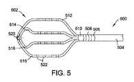
図5は、平面またはグリッド電極アセンブリ500の形態で示される、システム10での使用に適した別の例示的な電極アセンブリ12の斜視図である。グリッド電極アセンブリ500は、カテーテル本体504に連結されたパドル502を含む。例示された実施形態では、カテーテル本体504は、それに連結された本体電極506、508、510を含む。例示された実施形態では、パドル502は、近位カプラによってカテーテル本体504に連結され、パドル502の遠位端で遠位コネクタ520によって互いに連結された、第1のスプライン512と、第2のスプライン514と、第3のスプライン516と、第4のスプライン518と、を含む。一実施形態では、第1のスプライン512と第4のスプライン518は、1つの連続したセグメントである得、第2のスプライン514と第3のスプライン516は、別の連続したセグメントであり得る。他の実施形態では、種々のスプラインは、互いに連結された別個のセグメントであり得る。複数のスプラインは、異なる数の電極522をさらに備え得る。例示された実施形態における電極は、スプラインに沿って均等に間隔を空けて配置されたリング電極を備え得る。他の実施形態では、電極は、均等にまたは不均等に間隔を空けて配置され得、電極は、点電極または他のタイプの電極を備え得る。 FIG. 5 is a perspective view of another
電極522は、例えばおよびこれに限定されないが、心マッピングおよび/またはアブレーション(例えば、IREアブレーション)を含む種々の診断目的と治療目的のために使用されてもよい。例えば、グリッド電極アセンブリ500は、双極ベースの電気穿孔での使用のための双極電極アセンブリとして構成されてもよい。より具体的には、隣接する電極522が反対の極性に通電されて、隣接する電極522間に電位および対応する電場を生成するように、隣接する電極522は、電極対(例えば、カソード・アノード電極対)として構成されてもよく、(例えば、カテーテルシャフト44を通って延びる適切な電気的ワイヤまたは他の適切な導電体を介して)電気穿孔ジェネレータ26に電気的に連結されてもよい。双極対を形成する隣接する電極522は、同一のスプラインに沿って(例えば、第1のスプライン512に沿った電極522)、または隣接するスプラインを横切って位置していてもよい。一実施形態では、例えば、電極対は、第1のスプライン512上に位置する1つの電極522(例えば、カソード)と、隣接する第2のスプライン514上に位置する別の隣接する電極522(例えば、アノード)との間に形成されてもよい。他の実施形態では、電極522の任意の組み合わせは、例えばおよびこれに限定されないが、隣接する電極と、非隣接の電極と、隣接するスプライン上の電極と、非隣接のスプライン上の電極と、システム10が本明細書に記載されるように機能することを可能にする電極の任意の他の組み合わせと、を含む電極対(例えば、カソード・アノード電極対)として構成されてもよい。上記のように、例えば、電気穿孔ジェネレータ26および/またはコンピュータシステム32は、電極522と組織16との間の接触に基づいて電極対を形成するために、グリッド電極アセンブリ500の特定の電極522を選択的に通電してもよい。他の実施形態では、グリッド電極アセンブリ500は、単一極または単極電極アセンブリなど、双極電極アセンブリ以外として構成されてもよい。そのような実施形態では、電極18は、リターン電極として機能してもよい。
第1のスプライン512と、第2のスプライン514と、第3のスプライン516と、第4のスプライン518は、同一の(位相的)平面内に概して整列される。パドル502は、図5では、比較的平坦または平面として示されるが、パドル502は、曲がっていてもよく、カールしていてもよく、歪んでいてもよく、ねじれていてもよく、および/または他の方法で変形していてもよいことが理解されるべきである。したがって、パドル502とスプライン512、514、516、518によって画定される平面は、平面が非平坦な位相的平面であるように、対応して変形していてもよい。
図6は、拡張可能な電極アセンブリ600の形態で示される、システム10での使用に適した別の例示的な電極アセンブリ12の斜視図である。電極アセンブリ600は、長手方向軸606に概して沿って、電極アセンブリ600の近位端602から電極アセンブリ600の遠位端604まで軸方向に延びている。近位端602は、適切なカプラ(図示省略)を介して、カテーテルシャフト44に(例えば、シャフト44の遠位端に)連結される。例示的な実施形態では、ガイドワイヤ608は、シャフト44を通って、電極アセンブリ600を通って軸方向に延びている。ガイドワイヤ608は、身体17内での電極アセンブリ600の位置を調整するために、(例えば、ハンドル42を使用して)操作されてもよい。 FIG. 6 is a perspective view of another
電極アセンブリ600は、一般に、拡張可能な隔離部材610と、電極612、614の対と、を含む。より具体的には、拡張可能な隔離部材610は、拡張可能な隔離部材610の近位端616と拡張可能な隔離部材610の遠位端618との間を延びる。拡張可能な隔離部材610が、電極612、614の間で軸方向に配置されるように、電極612、614は、それぞれ、拡張可能な隔離部材610の近位端616と遠位端618に隣接して配置される。近位電極612は、拡張可能な隔離部材610の近位端616に隣接しており、電極アセンブリ600の近位端602に近接している。同様に、遠位電極614は、拡張可能な隔離部材610の遠位端618に近接しており、電極アセンブリ600の遠位端604に近接している。拡張可能な隔離部材610の遠位端618は、例示的な実施形態では、電極アセンブリ600の遠位端604に近接している。
電極612、614は、例えばおよびこれに限定されないが、心マッピングおよび/またはアブレーション(例えば、IREアブレーション)を含む種々の診断目的と治療目的のために使用されてもよい。例えば、電極アセンブリ600は、双極ベースの電気穿孔治療での使用のための双極電極アセンブリとして構成されてもよい。具体的には、IRE治療のために、電極612、614は、個々に(例えば、カテーテルシャフト44を通って延びる適切な電気的ワイヤまたは他の適切な導電体を介して)ジェネレータ26に電気的に連結され得、反対の極性で(例えば、電気穿孔ジェネレータ26および/またはコンピュータシステム32によって)選択的に通電されて、それらの間に電位および対応する電場を生成するように構成され得る。即ち、電極612、614のうち一方は、カソードとして機能するように構成され、他方は、アノードとして機能するように構成される。電極612、614は、任意の適切な電気穿孔電極であってもよい。例示的な実施形態では、電極612、614は、リング電極である。電極612、614は、任意の他の形状または構成を有していてもよい。電極612、614の形状、サイズおよび/または構成は、適用される電気穿孔治療の種々のパラメータに影響していてもよいと認識される。例えば、電極612、614の一方または両方の表面積を増加させることは、同一のレベルの組織破壊を引き起こすために必要とされる印加電圧を低減させ得る。さらに、近位電極612と遠位電極614のそれぞれは、単一の電極として示されているが、代替的には、近位電極612と遠位電極614の一方または両方は、2つ以上の個別の電極として具体化されてもよい。さらに、電極アセンブリ600は、双極電極アセンブリとして記載されている一方で、いくつかの実施形態では、電極アセンブリ600は、単極または単極電極アセンブリとして構成されてもよく、リターン電極または不関電極としてパッチ電極(例えば、リターン電極18)を使用してもよいことが理解されるべきである。
例示的な実施形態では、拡張可能な隔離部材610は、つぶれた構成(図示省略)と拡張された構成(図6参照)との間で構成可能である。例えば、拡張可能な隔離部材610は、つぶれた構成で、(例えば、カテーテルシャフト44内で軸方向に配置されて)身体17内の組織16の標的位置に伝達され、標的位置で、拡張された構成に移行される。拡張可能な隔離部材610は、標的位置で組織16と密着して係合し、(例えば、近位電極612から遠位電極614を少なくとも部分的に絶縁することによって)電極612、614間の電気的連通を妨げるように構成される。より具体的には、拡張可能な隔離部材610は、電気的絶縁材料から形成される。したがって、近位電極612と遠位電極614との間の電流フロー622は、拡張可能な隔離部材610の周りを迂回させられる。図6は、拡張可能な隔離部材610の周りでの変化する形状と迂回の度合いを示す複数の電流フロー622を示す。いくつかの実施形態では、拡張可能な隔離部材610の形状とサイズは、(例えば、得られた電流フロー622の迂回の度合い、形状または方向など)その周りの電流フロー622に影響を与えるように選択されてもよい。 In an exemplary embodiment,
さらに、拡張可能な隔離部材610は、拡張された構成にあるときに、組織16に密着して係合するように構成される。例示的な一実施形態では、拡張可能な隔離部材610が、患者の組織と係合したときに電極612、614間で流体連通を妨げ、結果として、電気的連通(例えば、電流フロー)を妨げるように、拡張可能な隔離部材610は、組織16と密着して係合するように構成された円周シール表面620を含む。例えば、拡張可能な隔離部材610が、肺静脈隔離(PVI)のために、または他の円筒状もしくは管状の組織(例えば、他の脈管構造組織)を隔離するために使用されるとき、拡張可能な隔離部材610は、その周りの血液の流れを妨げまたは実質的に防止する。したがって、電極612、614が通電されるとき、電流622は、血液を通ってではなく、拡張可能な隔離部材610に隣接する組織16を通って電極間に流れる。この方法で、電気穿孔治療は、より限局され、したがって、所望の量の細胞破壊を引き起こすために、低減された印加電圧を必要とする。具体的には、流体(例えば、血液)は、組織よりも高い電気伝導性を有し、したがって、電流は、組織を通るときよりも、容易に血流を通って流れ、電気穿孔治療は有効ではない。血液の流れを妨げることによって、電極612、614間の電流622は、隣接する組織16を通って迂回され、それにより、所与の電圧での電気穿孔治療の有効性を増加させる。 Further,
例示的な実施形態では、拡張可能な隔離部材610は、電気的絶縁材料から形成または構成された外側層624を含む。例えば、外側層624は、ポリエチレンテレフタレート(PET)を含んでもよい。作製された外側層624は、電気的に絶縁であり、電極アセンブリ600の拡張と収縮に適用可能な任意の他の適切な材料を含む。ある特定の実施形態では、図6に示されるように、拡張可能な隔離部材610は、膨張可能なバルーンとして具体化される。そのような実施形態では、膨張可能なバルーンは、(例えば、電極アセンブリ600が身体17内の標的位置に前進させられており、カテーテルシャフト44から広げられているときに)バルーンを選択的に膨張させるための流体供給源626に連結される。いくつかの実施形態では、流体供給源は、誘電性流体、例えば、脱イオン水、食塩水、二酸化炭素ガス、亜酸化窒素ガスおよび/または空気を含む。他の実施形態では、拡張可能な隔離部材610は、他の手段、例えば、外側層624内に保持された拡張可能なフレーム(例えば、形状記憶材料から形成されたフレーム)を使用して、選択的に拡張されてもよい。 In an exemplary embodiment, the
拡張可能な隔離部材610は、図6では、細長い球状形状を有するように示されているが、拡張可能な隔離部材610は、電極612、614間でシールし、従って流体的および/または電気的連通を妨げることを可能にする任意の他の形状または構成を有していてもよい。特定の形状および/または構成は、所望の特定の組織隔離のために選択されてもよい。例えば、他の実施形態では、(血管の比較的円筒状の隔離とは対照的に)固体または平面組織内、例えば、心腔の壁内での隔離と組織破壊が望まれてもよい。そのような実施形態では、拡張可能な隔離部材610の遠位端618は、反転されて凹んでいてもよく、遠位電極614は、遠位端618の凹んだ部分に位置していてもよい。電極612、614間の電流フロー622が、遠位端618と係合した(例えば、心腔壁の)組織を通って迂回されるように、遠位端618は、近位電極612から遠位電極614をシールまたは隔離するように、組織に対して係合されてもよく、または押し付けられてもよい。 Although
拡張可能な隔離部材610と隣接する組織16との間での完全なシールが発生しなくてもよいことが企図される。例えば、円周シール表面620は、組織16と完全に係合しなくてもよく、円周シール表面620を通り過ぎる一部の流体(血液)フローが発生してもよい。いくつかの実施形態では、完全な係合またはシールは、電気穿孔治療をうまく進めるために必要ではない。シールのレベルは、種々の方法を使用して確かめられてもよい。いくつかの実施形態では、導入する蛍光透視造影材料は、拡張可能な隔離部材610の上流で血流内に導入され、拡張可能な隔離部材610の下流での造影材料の存在または量は、X線を使用して測定される。他の実施形態では、ドップラー超音波は、拡張可能な隔離部材610を通り過ぎる流体フローのレベルを測定するために使用される。さらなる他の実施形態では、電極612、614の間のインピーダンスは、標的位置への電極アセンブリ600の配置の前および後に測定され、インピーダンスにおける閾値のシフトは、十分なシールを反映する。さらなる他の実施形態では、電極アセンブリ600は、拡張可能な隔離部材610と組織16との間のシールのレベルを反映するために、流体圧力を測定するために使用される遠位端604上の圧力トランスデューサ(図示省略)を含む。シールのレベルを決定するための追加のおよび/または代替的な方法が使用されてもよい。さらに、任意の上記方法は、反復的に使用されてもよい。具体的には、シールの初期レベルが決定されてもよく、それに応じて、電極アセンブリ600の位置が調整されてもよい。適切なまたは十分なレベルのシールが(例えば、閾値および/または医師の決定に基づいて)達成されるまでに、シールのその後のレベルが決定されてもよい。 It is contemplated that a complete seal between
さらに、任意の上記方法(または任意の他の適切な方法)を使用して決定されたシールのレベルに基づいて、印加電圧の適切なレベルが選択されてもよい。低減されたレベルのシールは、増加された印加電圧を必要としてもよい。 Additionally, the appropriate level of applied voltage may be selected based on the level of seal determined using any of the above methods (or any other suitable method). A reduced level of sealing may require an increased applied voltage.
電極アセンブリ12は、本明細書に示され記載された特定の構成に限定されず、任意の他の適切な電極アセンブリを含んでもよく、システム10が本明細書に記載されるように機能することを可能にする任意の他の適切な構成を有してもよいことが理解されるべきである。例として、電極アセンブリ12は、米国特許第10,136,829号と、米国特許出願公開第2018/0014751号および第2019/0201688号と、国際特許出願公開番号WO2018/208795と、米国仮特許出願第62/861,135号、第62/842,654号、および第62/983,200号に記載される電極アセンブリと同一または類似の構成を有してもよく、それらの開示の全体が参照により本明細書に組み込まれる。
図1を再び参照すると、可視化、ナビゲーションおよび/またはマッピングシステム30は、電場ベースのシステム、または時折、インピーダンスベースのシステムと呼ばれ、例えば、モデル名EnSite NAVX(商標)システムを有し、Abbott Laboratoriesから市販されるもの、およびその全開示が参照により本明細書に組み込まれる表題が「Method and Apparatus for Catheter Navigation and Location and Mapping in the Heart」である米国特許第7,263,397号を参照して一般に示されるものなどを備え得る。可視化、ナビゲーションおよび/またはマッピングシステム30はまた、Abbott LaboratoriesのEnSite(商標)Velocity(商標)またはEnSite Precision(商標)心マッピングおよび可視化システムを含む、他の市販のシステムを含んでもよい。他の例示的な実施形態では、可視化、ナビゲーションおよび/またはマッピングシステム30は、他のタイプのシステム、例えばおよびこれに限定されないが、磁場ベースのシステム、例えば、Biosense Websterから入手可能な(現在、インピーダンスおよび磁気式駆動の電極とのハイブリッド形態である)CARTOシステム、またはMediGuide LtdのgMPSシステムなどを含んでもよい。電場ベースおよび磁場ベースのシステムの組み合わせに従って、カテーテルは、インピーダンスベースの電極としての電極と、1つ以上の磁場検知コイルと、の両方を含み得る。一般に入手可能な蛍光透視、コンピュータ断層撮影(CT)、および核磁気共鳴画像法(MRI)ベースのシステムはまた、使用され得る。 Referring again to FIG. 1, the visualization, navigation and/or
電気穿孔ジェネレータ26は、あらかじめ決定され得るまたはユーザにより選択可能であり得る電気穿孔の通電の戦略に従って、電極要素に通電するように構成される。電気穿孔により引き起こされる一次壊死の治療のために、ジェネレータ26は、電流を生じさせるように構成されてもよく、電流は、密集して配置される電極(例えば、電極アセンブリ12の電極対)間に伝達される短い持続時間のDCパルスであって、(例えば、組織部位において)約0.1~1.0kV/cmの電場強度を伝達することが可能な短い持続時間のDCパルスの形態のパルスされた電場として、電極アセンブリ12を介して伝達される。不可逆電気穿孔のために必要とされる電圧振幅とパルス持続時間は、反比例する。例えば、パルス持続時間が減少すると、電圧振幅は、電気穿孔を達成するために増加されなければならない。
いくつかの実施形態では、電極アセンブリ12の電極は、いくつかの電極のみが所定の時間において通電されるように、順番に通電されてもよい。即ち、電極アセンブリ12の電極の全てが同時に通電されるわけではない。いくつかの実施形態では、例えば、電極の第1の対が、電気穿孔の通電の戦略に従って通電されてもよく、続いて、電極の第2の対が、電気穿孔の通電の戦略に従って通電されてもよい。電極への順次の通電は、電極の第3の対、電極の第4の対などに続けられてもよい。電極の対は、隣接するまたは非隣接の電極を含んでもよい。例として、電極アセンブリが、位置(即ち、第2の電極が、第1の電極と第3の電極に隣接する)に従って1からnまで順番に番号付けされた複数の電極を含む場合、電極は、順番に、第1および第2の電極、第3および第4の電極、第5および第6の電極などを通電することによって、対として順番に通電されてもよい。別の例では、電極は、順番に、第1および第2の電極、第2および第3の電極、第3および第4の電極などを通電することによって、対として順番に通電されてもよい。さらなる別の例では、電極は、順番に、第1および第3の電極、第2および第4の電極、第3および第5の電極などを通電することによって、対として順番に通電されてもよい。電極アセンブリの電極を順番に通電するためのさらなるシステムと方法は、例えば、2020年11月4日出願の米国仮特許出願第63/109,520号に記載され、その開示の全体が参照により本明細書に組み込まれる。順次の通電は、単極の構成と双極の構成の両方で使用されてもよい。 In some embodiments, the electrodes of
例示的な実施形態では、電気穿孔ジェネレータ26は、時折、本明細書でDCエネルギー源とも呼ばれ、極性が交互に切り替わる一連のDCパルス、即ち、方向が交互に切り替わる電流を生じさせる連続的なDCパルスを生成するように構成されている二相性電気穿孔ジェネレータ26である。他の実施形態では、電気穿孔ジェネレータは、単相性または多相性電気穿孔ジェネレータである。いくつかの実施形態では、電気穿孔ジェネレータ26は、選択可能なエネルギーレベルで、例えば、50ジュール、100ジュール、200ジュールなどで、DCパルスでのエネルギーを出力するように構成される。他の実施形態は、より大きいまたはより少ないエネルギーの設定を有していてもよく、利用可能な設定の値は、同一または異なっていてもよい。いくつかの実施形態では、電気穿孔ジェネレータ26は、約500Vと約3.5kVとの間、約600Vと2.5kVとの間、約800Vと約3.5kVとの間、約600Vと約2.0kVとの間、約800Vと約2.5kVとの間、約1.0kVと約3.5kVとの間、約600Vと約1.5kVとの間、約800Vと約2.0kVとの間、または約1.0kVと約2.5kVとの間のピーク値を有するDCパルスを出力または生成する。他の実施形態は、任意の他の適切な電圧を出力または生成してもよい。 In an exemplary embodiment, the
可変インピーダンス27は、システムのインピーダンスが変動することを可能にする。さらに、可変インピーダンス27は、電気穿孔ジェネレータ26の出力の1つ以上の特徴、例えば、振幅、持続時間、パルス形状などを変化させるために使用されてもよい。別の構成要素として示されているが、可変インピーダンス27は、カテーテル14またはジェネレータ26内に組み込まれてもよい。可変インピーダンス27は、直列で、並列で、または直列および/または並列の組み合わせで接続された1つ以上のインピーダンス要素、例えば、レジスタ、キャパシタまたはインダクタ(図示省略)を含む。例示された実施形態では、可変インピーダンス27は、カテーテル14と直列に接続される。代替的には、可変インピーダンス27のインピーダンス要素は、カテーテル14と並列に、またはカテーテル14と直列および並列の組み合わせで、接続されてもよい。さらに、他の実施形態では、可変インピーダンス27のインピーダンス要素は、リターン電極18と直列および/または並列に接続される。いくつかの実施形態は、1つよりも多い可変インピーダンス27を含み、それぞれが、1つ以上のインピーダンス要素を含んでもよい。そのような実施形態では、各可変インピーダンス27は、インピーダンスが各カテーテル電極を介して、またはカテーテル電極の群を介して独立して変化されることを可能にするように、別のカテーテル電極またはカテーテル電極の群に接続されてもよい。他の実施形態では、システム10のインピーダンスは、変化される必要がなくてもよく、可変インピーダンス27は、省略されてもよい。
電気穿孔ジェネレータ26は、パルス信号を生成し、IREの望ましくないまたは意図しない作用を低減、最小化または防止するように構成された電極アセンブリ12の電極にパルス信号を供給するように構成される。例えば、従来のIRE治療システムは、高振幅で短い持続時間のDC電気(IRE)パルスの印加によって、骨格筋収縮を引き起こし得る。そのような骨格筋収縮は、一般には望ましくなく、例えば、それらが、患者の身体を動かすことによって、電気解剖学的マップ(例えば、IRE治療前に収集されたもの)を不正確にし得るためである。さらに、従来のIRE治療システムは、例えば、電極で、患者内で望ましくないガスを生成し得る。
電気穿孔ジェネレータ26によって生成されたパルス信号は、具体的には、骨格筋と神経(例えば、横隔神経)、さらには心筋のアクティブ化を防止するように(例えば、位相と、振幅と、パルス持続時間を制御することによって)形作られる。心筋のアクティブ化を回避することによって、電気穿孔ジェネレータによって生成されたパルス信号は、(例えば、R波に従う)心周期またはリズムに基づいて時間調整される必要もなく、ゲートされる必要もない。より具体的には、電気穿孔ジェネレータ26によって生成されたパルス信号は、神経刺激または筋肉のアクティブ化に関連する強度-持続時間曲線を下回るパルス持続時間と電圧振幅を有するように形作られる。電気穿孔ジェネレータ26によって生成されたパルス信号は、比較的高い強度(即ち、電圧)と周波数(即ち、短いパルス持続時間)である。例として、電気穿孔ジェネレータ26によって生成されたパルス信号は、500V~3.5kV、600V~2.5kV、800V~3.5kV、600V~2.0kV、800V~2.5kV、1.0kV~3.5kV、600V~1.5kV、800V~2.0kVまたは1.0kV~2.5kVの範囲の電圧振幅と、1ナノ秒~100マイクロ秒(μs)、1ナノ秒~50μs、0.1μs~100μs、1ナノ秒~20μs、0.1μs~50μs、1μs~100μs、1ナノ秒~15μs、0.1μs~20μs、0.5μs~50μs、1ナノ秒~10μs、0.1μs~15μs、1ナノ秒~5μs、0.1μs~10μs、0.1μs~5μs、5μs未満、4μs未満、3μs未満、および2μs未満の範囲のパルス持続時間を有していてもよい。他の実施形態では、電気穿孔ジェネレータ26によって生成されたパルス信号は、500V未満の、または3.5kVよりも大きい電圧振幅を有し得、100μsよりも長い、または1ナノ秒未満のパルス持続時間を有し得る。一般に、(例えば、連続した損傷を生じさせるため)有効なIREのために必要とされる電圧振幅とパルス持続時間は、反比例し、神経刺激または筋肉アクティブ化を回避するための電圧と持続時間の範囲内で選択される。 The pulse signal generated by
図7は、電気穿孔ジェネレータ26によって生成された例示的なパルス信号700を示すプロットであり、垂直軸は電圧(V)を示し、水平軸は時間(T)を示す。図7に示されるように、パルス信号700は、第1の極性と第1のパルス持続時間706を有する第1の電圧振幅704を有している第1の相702と、第1の極性とは反対の第2の極性と第2のパルス持続時間712を有する第2の電圧振幅710を有している第2の相708と、を含む二相性パルス信号である。第2の相708が、第1の相702の後にゼロではない間隔716で生成されるように、示されたパルス信号700はまた、第2の相708を第1の相702から分離する第3のゼロ電圧相714を含む(即ち、パルス信号700は、ゼロの電圧出力を有する)。他の実施形態では、第2の相708が第1の相702の直後に生成されるように、パルス信号700は、第3の相714を含んでいなくてもよい。 FIG. 7 is a plot showing an
例示された実施形態では、第1の相702は、正の電圧を有し、第2の相708は、負の電圧を有する。他の実施形態では、第1の相702が負の電圧を有していてもよく、第2の相708が正の電圧を有していてもよい。さらに、例示された実施形態では、パルス信号700は、二相性信号として示されて記載されているが、他の実施形態では、パルス信号700は、二相性信号以外であってもよい(例えば、パルス信号700は、単相性または多相性であってもよい)。 In the illustrated embodiment,
さらに、例示された実施形態では、第1の相702と第2の相708は、同一の電圧振幅または電圧値を有し、同一のパルス持続時間を有する(即ち、第1のパルス持続時間706は、第2のパルス持続時間712と等しい)。即ち、パルス信号700は、対称的なパルス信号である。他の実施形態では、パルス信号700が非対称になるように、第1の相702は、第2の相708と異なる電圧振幅または電圧値、および/またはパルス持続時間を有していてもよい。 Further, in the illustrated embodiment,
第1の相702と第2の相708は、同時に骨格筋を刺激することを回避しつつ、IREによるアブレーションを引き起こすのに十分な任意の適切な電圧振幅とパルス持続時間を一般に有していてもよい。いくつかの実施形態では、例えば、第1の電圧振幅704と第2の電圧振幅710のそれぞれは、500V~3.5kV、600V~2.5kV、800V~3.5kV、600V~2.0kV、800V~2.5kV、1.0kV~3.5kV、600V~1.5kV、800V~2.0kVまたは1.0kV~2.5kVの範囲であり、第1のパルス持続時間706と第2のパルス持続時間712のそれぞれは、1ナノ秒~100μs、1ナノ秒~50μs、0.1μs~100μs、1ナノ秒~20μs、0.1μs~50μs、1μs~100μs、1ナノ秒~15μs、0.1μs~20μs、0.5μs~50μs、1ナノ秒~10μs、0.1μs~15μs、1ナノ秒~5μs、0.1μs~10μs、0.1μs~5μs、5μs未満、4μs未満、3μs未満、および2μs未満の範囲である。特定の一実施形態では、第1の電圧振幅704と第2の電圧振幅710のそれぞれは、約1.0kVであり、第1のパルス持続時間706と第2のパルス持続時間712のそれぞれは、約2μsである。別の特定の実施形態では、第1の電圧振幅704と第2の電圧振幅710のそれぞれは、約1.4kVであり、第1のパルス持続時間706と第2のパルス持続時間712のそれぞれは、約2μsである。 The
第3の相714の間隔716は、一般に、パルス信号700の第1の相702と第2の相708が骨格筋をアクティブ化すること、または刺激することを防止する、または回避するのに十分な持続時間になるように選択される。間隔716は、一般に、50μs未満であり、例えばおよびこれに限定されないが、30μs未満、20μs未満、15μs未満、10μs未満、5μs未満、4μs未満、3μs未満、2μs未満、およびさらには1μs未満であり得る。例示された実施形態では、間隔716は、約2.5μsである。別の特定の実施形態では、間隔716は、約2μsである。 The
いくつかの実施形態では、パルス信号700(即ち、第1の相702と第2の相708)の電圧振幅は、システム10で使用される電極アセンブリ12のタイプに基づいて選択されてもよい。より具体的には、ある特定のタイプの電極アセンブリが、他の電極アセンブリよりも高い電圧のために評価されてもよく、パルス信号700は、適宜調整されてもよい。いくつかの実施形態では、例えば、パルス信号700(即ち、第1の相702と第2の相708)は、バスケット型電極アセンブリ(例えば、図4に示されるバスケット電極アセンブリ400)と比較して、ループ型電極アセンブリ(例えば、図2および図3に示される電極ループアセンブリ200)と共に使用されるときに、より高い電圧振幅を有していてもよい。特定の一実施形態では、パルス信号700の電圧振幅は、ループ型電極アセンブリと共に使用されるときに、1kV~2.5kVの範囲であり、バスケット型電極アセンブリと共に使用されるときに、800V~1.5kVの範囲内である。 In some embodiments, the voltage amplitudes of pulse signal 700 (ie,
パルス信号700の特徴(例えば、電圧振幅、第1および第2のパルス持続時間706、712など)はまた、電極アセンブリ12が単極電極アセンブリとして構成されるかどうか、または双極電極アセンブリとして構成されるかどうかに従って、調整されてもよい。例えば、骨格筋回復は、双極IREと比較して、単極IREでより顕著であり得る。したがって、単極IREで使用されるパルス信号は、双極IREと比較して、より狭いまたはより厳密な範囲の許容できるパルス特徴(例えば、電圧振幅とパルス持続時間)を有していてもよい。 Characteristics of pulse signal 700 (eg, voltage amplitude, first and
一例では、単極電極アセンブリとして構成されたループ型電極アセンブリ(例えば、図2および図3に示される電極ループアセンブリ200)は、500V~3.5kVの範囲または800V~3.0kVの範囲の電圧振幅と、0.5μs~3.0μsの範囲または0.5μs~1.5μsの範囲の第1および第2のパルス持続時間706、712と、を有するパルス信号700を利用してもよい。双極電極アセンブリとして構成されたループ型電極アセンブリ(例えば、図2および図3に示される電極ループアセンブリ200)は、500V~3.5kVの範囲または600V~1.4kVの範囲の電圧振幅と、0.5μs~3μsの範囲または1μs~1.5μsの範囲の第1および第2のパルス持続時間706、712と、を有するパルス信号700を利用してもよい。 In one example, a looped electrode assembly configured as a monopolar electrode assembly (eg, the
別の例では、単極電極アセンブリとして構成されたバスケット型電極アセンブリ(例えば、図4に示されるバスケット電極アセンブリ400)は、500V~3.5kVの範囲の電圧振幅と、0.5μs~3μsの範囲の第1および第2のパルス持続時間706、712と、を有するパルス信号700を利用してもよい。双極電極アセンブリとして構成されたバスケット型電極アセンブリ(例えば、図4に示されるバスケット電極アセンブリ400)は、500V~3.5kVの範囲の電圧振幅と、0.5μs~3μsの範囲内の第1および第2のパルス持続時間706、712と、を有するパルス信号700を利用してもよい。 In another example, a basket electrode assembly configured as a monopolar electrode assembly (eg,
別の例では、単極電極アセンブリとして構成されたグリッド電極アセンブリ(例えば、図5に示されるグリッド電極アセンブリ500)は、500V~3.5kVの範囲の電圧振幅と、0.5μs~3μsの範囲の第1および第2のパルス持続時間706、712と、を有するパルス信号700を利用してもよい。双極電極アセンブリとして構成されたグリッド電極アセンブリ(例えば、図5に示されるグリッド電極アセンブリ500)は、500V~3.5kVの範囲の電圧振幅と、0.5μs~3μsの範囲の第1および第2のパルス持続時間706、712と、を有するパルス信号700を利用してもよい。 In another example, a grid electrode assembly configured as a monopolar electrode assembly (eg,
さらなる別の例では、双極電極アセンブリとして構成された拡張可能な電極アセンブリ(例えば、図6に示される拡張可能な電極アセンブリ600)は、500V~3.5kVの範囲、500V~2.5kVの範囲、600V~3.0kVの範囲、600V~2.5kVの範囲、または800V~2.5kVの範囲の電圧振幅と、400ナノ秒~20μsの範囲または500ナノ秒~1.5μsの範囲の第1および第2のパルス持続時間706、712と、を有するパルス信号700を利用してもよい。さらに、拡張可能な電極アセンブリ(例えば、図6に示される拡張可能な電極アセンブリ600)のために使用されるパルス信号700は、350ナノ秒~1msの範囲または500ナノ秒~1.5μsの範囲の、第1の相702と第2の相708との間の間隔716を有していてもよい。 In yet another example, an expandable electrode assembly configured as a bipolar electrode assembly (eg,
複数のパルス信号700が反復するパルス期間で電極アセンブリ12の電極に生成されて印加されるように、電気穿孔ジェネレータ26は、反復するパターンでパルス信号700を生成してもよい。そのような複数のパルス信号700は、本明細書では総称してバースト信号と呼ばれる。
図8は、パルス期間802で生成された2つのパルス信号700を含む例示的なバースト信号800を示す。パルス期間802は、システム10が本明細書に記載されるように機能することを可能にする任意の適切な期間であってもよい。例として、パルス期間802は、0.5ミリ秒(ms)~50ms、1ms~50ms、0.5ms~30ms、1ms~30ms、0.5ms~25ms、0.5ms~20ms、1ms~25ms、0.5ms~10ms、1ms~20ms、1ms~10ms、0.5ms~5ms、および1ms~5msの範囲であってもよい。例示された実施形態では、パルス期間802は、約4msである。いくつかの実施形態では、パルス期間802は、標的電圧振幅またはその近傍(例えば、標的電圧振幅の少なくとも90%)でパルス信号700の電圧振幅を維持するのに十分な電圧まで、電気穿孔ジェネレータ26の電力供給体(例えば、キャパシタ)を再充電することを可能にするように選択される。 FIG. 8 shows an
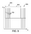
いくつかの実施形態では、複数のバースト信号がバースト期間と呼ばれる反復する期間で電極アセンブリ12の電極に生成されて印加されるように、電気穿孔ジェネレータ26は、反復するパターンでバースト信号を生成してもよい。図9は、例えば、反復するバースト期間902に生成された例示的なバースト信号900を示す。バースト期間902は、システム10が本明細書に記載されるように機能することを可能にする任意の適切な期間であってもよい。例として、バースト期間902は、50ms~5秒(s)、100ms~5s、100ms~2s、100ms~1s、200ms~1s、200ms~800ms、および300ms~700msの範囲であってもよい。例示された実施形態では、バースト期間902は、約500msである。いくつかの実施形態では、バースト期間902は、標的電圧振幅またはその近傍(例えば、標的電圧振幅の少なくとも90%)でパルス信号700の電圧振幅を維持するのに十分な電圧まで、電気穿孔ジェネレータ26の電力供給体(例えば、キャパシタ)を再充電することを可能にするように選択される。さらにまたは代替的には、バースト期間902は、患者の心周期またはリズムに基づいて変化してもよい。一実施形態では、例えば、バースト信号900は、(例えば、患者の心拍と同期する)R波ゲート戦略に従って生成される。そのような実施形態では、バースト信号900は、心電図中のR波の検出に応答して生成されてもよく、またはそれに基づいて誘発されてもよい。そのような実施形態では、バースト期間902は、可変(即ち、固定されておらず、または一定でない)であってもよい。例えば、バースト期間902は、500ms~1.5sの範囲、600ms~1.2sの範囲、またはシステム10が本明細書に記載されるように機能することを可能にする任意の他の適切な範囲で変化してもよい。そのようなバースト期間とゲート戦略は、本明細書に記載される任意の電極アセンブリに関して使用されてもよい。 In some embodiments,
図9に示されるプロットは、2つのバースト信号900を含むが、電気穿孔ジェネレータ26は、2つよりも多くのバースト信号900を生成してもよいことが理解されるべきである。例として、電気穿孔ジェネレータ26は、少なくとも5つのバースト信号、少なくとも10個のバースト信号、少なくとも20個のバースト信号、少なくとも30個のバースト信号、少なくとも40個のバースト信号、少なくとも50個のバースト信号、少なくとも75個のバースト信号、少なくとも100個のバースト信号、または最大で200個のバースト信号を含む(即ち、反復するバースト期間902での)バースト信号900のシリーズを生成してもよい。他の実施形態では、電気穿孔ジェネレータ26は、反復するバースト期間で、200個よりも多くのバースト信号のシリーズを生成してもよい。 Although the plot shown in FIG. 9 includes two burst
さらに、例示された実施形態では、バースト信号900は、5つのパルス信号700を含むが、バースト信号900は、システム10が本明細書に記載されるように機能することを可能にする任意の適切な数のパルス信号700を含んでもよいことが理解されるべきである。例として、バースト信号900は、少なくとも10個のパルス信号、少なくとも15個のパルス信号、少なくとも20個のパルス信号、少なくとも30個のパルス信号、少なくとも40個のパルス信号、少なくとも50個のパルス信号、少なくとも75個のパルス信号、少なくとも100個のパルス信号、少なくとも150個のパルス信号、または最大で200個のパルス信号を含んでもよい。他の実施形態では、バースト信号900は、5つ未満のパルス信号700、または200個よりも多いパルス信号700を含んでもよい。特定の一実施形態では、バースト信号900は、50個のパルス信号700を含み、0.5sのバースト期間902を有する。別の特定の実施形態では、バースト信号900は、1,000個のパルス信号700を含み、0.5sのバースト期間902を有する。そのようなバースト信号とバースト期間は、本明細書に記載される任意の電極アセンブリの使用に適する。 Further, in the illustrated embodiment, burst
電気穿孔ジェネレータ26によって生成されたパルス信号の比較的高い電圧と短いパルス持続時間は、電気穿孔ジェネレータ26、その構成要素、カテーテル14、または患者の組織16中に導入され、システム10の動作に潜在的に不利に影響を与える、顕著な電磁干渉(EMI)またはノイズを生じ得る。したがって、本開示の実施形態は、高振幅で短い持続時間のパルス信号を生じさせる目的のために、ノイズの供給源を低減させるとともに、電気穿孔ジェネレータ26内での高周波数高電圧の切り換え作用を軽減するある特定の特徴を含む。 The relatively high voltage and short pulse duration of the pulse signal generated by
例えば、図10は、例示的な電気穿孔ジェネレータ26の概略図である。電気穿孔ジェネレータ26は、トリガ信号1004に応答したパルス信号の生成を制御するマイクロコントローラ1002または他のプログラム可能な処理デバイスを含む。トリガ信号1004は、電気穿孔ジェネレータ26では内部で、または別のシステムによっては外部で生成されてもよい。ある特定の実施形態では、トリガ信号は、例えば、ユーザによって作動されるスイッチまたはボタンにより切り換え回路が少なくとも瞬間的に閉じられる結果としてマイクロコントローラ1002に供給される個別の論理レベルDC信号である。トリガ信号1004に応答して、マイクロコントローラ1002は、例えば、単一のパルス、パルスのバースト、または複数のバーストを開始させる。 For example, FIG. 10 is a schematic diagram of an
マイクロコントローラ1002は、単一のパルス信号の生成において、複数の半導体スイッチを制御する目的のために、第1のパルス制御信号1006と第2のパルス制御信号1008を生成する。第1のパルス制御信号1006と第2のパルス制御信号1008は、マイクロコントローラ1002によって生成される論理レベルDC信号である。半導体スイッチは、高電圧スタンドオフで高電流伝導が可能であり、高周波数で動作可能である任意の適切な電力半導体、例えば、絶縁ゲート双極トランジスタ(IGBT)であってもよい。図10の実施形態では、半導体スイッチは、カテーテル14と、より具体的には、パルス信号を電極アセンブリ12に伝達する第1および第2の導体1022、1024への、正の高電圧DC(+HVDC)供給体1018と負の高電圧DC(-HVDC)供給体1020の印加を調節するために、ブリッジの構成で接続されるIGBT1010、1012、1014、1016として実装される。マイクロコントローラ1002は、パルス信号のバーストの生成において、各パルス信号を生じさせるために、高周波数(例えば、約500キロヘルツ)で整流するようにIGBT1010、1012、1014、1016を制御する。 The
マイクロコントローラ1002は、オプトアイソレータ1026によって、IGBT 1010、1012、1014、1016に連通可能に連結され、IGBT 1010、1012、1014、1016から電気的に隔離される。オプトアイソレータ1026は、オプトカプラとも呼ばれ、例えば、IGBT1010、1012、1014、1016の高周波数の切り換えによって生成されるノイズがマイクロコントローラ1002に到達することを防止する。オプトアイソレータ1026は、第1のパルス制御信号1006と第2のパルス制御信号1008を、マイクロコントローラ1002から、2つの論理レベルDC信号を4つのゲート駆動信号1030、1032、1034、1036に変換する論理回路1028にリレーする。論理回路1028は、ゲート駆動信号1030、1032、1034、1036のそれぞれを、第1のパルス制御信号1006と第2のパルス制御信号1008から得て、ゲート駆動信号1030、1032、1034、1036が、例えば、パルス信号の+HVDC相から-HVDC相への移行の間に瞬間的に、反対の極性のHVDC供給体(+HVDC供給体1018と-HVDC供給体1020)を、接続しない、または短絡しないことを保証する。例えば、ある特定の実施形態では、論理回路1028は、ゲート駆動信号1034、1036を、ゲート駆動信号1030、1032と逆のものとして得る。
一般に、少なくともいくつかの実施形態では、マイクロコントローラ1002は、IGBT1010、1012、1014、1016のゲートを駆動するのに十分な電流を発生させない。電力半導体スイッチのためのゲート電流は、典型的には、高電圧と高電流容量に伴って上昇する。したがって、電気穿孔ジェネレータ26は、それぞれIGBT1010、1012、1014、1016を動作させるためのゲートドライバ1038、1040、1042、1044を含む。ゲートドライバ1038、1040、1042、1044は、マイクロコントローラ1002と他のデジタル回路の態様を、電気穿孔ジェネレータ26の高電圧高電流部分からさらに隔離する。ゲートドライバ1038、1040、1042、1044は、ゲート駆動信号1030、1032、1034、1036に従って、IGBT1010、1012、1014、1016の整流を制御する。ゲートドライバ1038、1040、1042、1044は、ゲート駆動インピーダンス1046、1048、1050、1052を介して、IGBT1010、1012、1014、1016のゲートを駆動する。ゲート駆動インピーダンス1046、1048、1050、1052は、IGBT1010、1012、1014、1016を介して十分な電流上昇を生じさせるため、およびIGBT1010、1012、1014、1016による振動応答を回避するために選択される。ある特定の実施形態では、ゲート駆動インピーダンス1046、1048、1050、1052は、6~8オームの範囲のレジスタである。少なくともいくつかの実施形態では、ゲート駆動インピーダンス1046、1048、1050、1052は、6.8オームのレジスタである。 Generally, in at least some embodiments, the
ある特定の実施形態では、電気穿孔ジェネレータ26は、マイクロコントローラ1002と、オプトアイソレータ1026と、論理回路1028と、ゲートドライバ1038、1040、1042、1044と、IGBT1010、1012、1014、1016がその上に配置されてもよい1つ以上の印刷回路基板(PCB)に実装されてもよい。PCB上の少なくとも一部のトレースは、高周波数で切り換えられる高電圧DCを伝導する。例えば、+HVDC供給体1018をIGBT1010、1012、1014、1016に接続するトレースと、電流をIGBT1010、1012、1014、1016から第1および第2の導体1022、1024用の端子1056、1058に供給するトレースはそれぞれ、IGBT1010、1012、1014、1016の高周波数の切り換えによって生成されるパルス信号を運び、したがって、ノイズを電気穿孔ジェネレータ26に導入することに対して影響を受けやすい。ある特定の実施形態では、そのようなトレースは、これらのトレース上の周期的な高di/dtの条件から生じるノイズの導入を低減させるために十分に幅広く、可能な限り短くなければならない。ある特定の実施形態では、これらのトレースは、少なくとも0.12インチの幅でなければならない。同様に、少なくともいくつかのトレースは、IGBT1010、1012、1014、1016のゲートを駆動する目的のために、顕著な量の高周波数の切り換えされた電流を伝導する。例えば、ゲートドライバ1038、1040、1042、1044と、そのそれぞれのIGBT1010、1012、1014、1016との間に延びるトレースのそれぞれもまた、これらのトレース上の高di/dt条件から生じるノイズの導入をすることに対して影響を受けやすい。したがって、これらのトレースもまた、ノイズの導入を低減させるために十分に幅広く、可能な限り短くなければならない。ある特定の実施形態では、例えば、ゲートドライバ1038、1040、1042、1044と、そのそれぞれのIGBT1010、1012、1014、1016との間のトレースは、少なくとも0.06インチの幅でなければならない。 In one particular embodiment, the
ある特定の実施形態では、電気穿孔ジェネレータ26は、ゲートドライバ1038、1040、1042、1044のそれぞれとIGBT1010、1012、1014、1016との間に追加の構成要素を含む。例えば、ある特定の実施形態では、1つ以上のキャパシタは、ゲートを駆動するための電流供給体として機能するために、半導体スイッチのゲートと並列に連結される。ある特定の実施形態では、1つ以上のダイオードは、例えば、瞬間的な電圧抑制体として、または電流遮断デバイスとして機能するために、半導体スイッチのゲートと並列に連結される。ある特定の実施形態では、1つ以上のEMI抑制デバイスは、例えば、IGBT1010、1012、1014、1016の高周波数切り換えに起因するノイズを軽減するために、ゲート駆動ブランチに連結される。 In certain embodiments,
ある特定の実施形態では、電気穿孔ジェネレータ26は、高電圧DC出力体と直列に、即ち、第1および第2の導体1022、1024と直列に接続される1つ以上のインピーダンス整合回路(図示省略)を含む。インピーダンス整合回路は、+HVDC供給体1018と、-HVDC供給体1020と、カテーテル14の電極アセンブリ12との間のトレースまたは他の導体によって形成される高電圧DC伝送ラインの種々の部分に発生し得るまたは固有であり得るインピーダンス不連続を軽減する。例えば、インピーダンス不連続は、カテーテル14が電気穿孔ジェネレータ26に接続する位置に存在してもよく、システム10でのノイズと損失として最終的に顕在化する電気穿孔ジェネレータ26内での信号反射を生じ得る。 In one particular embodiment, the
+HVDC供給体1018と-HVDC供給体1020は、反対の極性のDC電圧レベルである。例えば、ある特定の実施形態では、+HVDC供給体1018は、約3500VDCの電位であってもよく、-HVDC供給体1020は、約ゼロの電位であってもよく、または事実上グラウンドであってもよい。電気穿孔ジェネレータ26は、少なくともいくつかの実施形態では、電極アセンブリ12のための高電圧電流供給源として機能する高電圧キャパシタ1054を含む。単一のパルス信号は、第1の極性の高電圧を有する第1の相と、約ゼロボルトの電位を有する第2の相と、第2の極性の高電圧を有する第3の相と、を含む。カテーテル14は、第1および第2の導体1022、1024に高電圧パルス信号を供給する。したがって、高電圧パルス信号の極性は、+HVDC供給体1018を第1の導体1022と第2の導体1024に、-HVDC供給体1020を第2の導体1024と第1の導体1022に、調子を合わせて交互に印加することによって、切り替えられてもよい。同様に、0(ゼロ)VDCは、第1および第2の導体1022、1024の両方との接続を遮断し、それらの電位をフロートさせることによって達成される。結果として、患者の身体17内の血液/生理食塩水の伝導特性により、電極アセンブリ12の電極間に電位がないはずであり、したがって、第1の導体1022と第2の導体1024との間に電位がない。 +
例えば、+HVDC供給体1018が約3500VDCの電位であり、-HVDC供給体1020が約0VDCの電位であるとき、パルス信号の第1の相は、+HVDC供給体1018を第1の導体1022に印加するために、IGBT1010を閉じてIGBT1014を開けることによって生じ、-HVDC供給体1020を第2の導体1024に印加するために、IGBT1012を閉じ、IGBT1016を開けることによって生じ、それにより、第1の持続時間にわたって+3500VDCの信号を生じさせる。第1の持続時間の後に、IGBT1010とIGBT1012は、第1および第2の導体1022、1024の電位をフロートさせるために開けられ、それにより、第2の持続時間にわたってパルス信号の第2の相のために0(ゼロ)VDCを生じさせる。第2の持続時間の後に、IGBT1014は、-HVDC供給体1020を第1の導体1022に印加するために閉じられ、IGBT1016は、+HVDC供給体1018を第2の導体1024に印加するために閉じられ、それにより、第3の持続時間にわたって-3500VDCの信号を生じさせる。第3の持続時間の後に、IGBT1014とIGBT1016は、第1および第2の導体1022、1024を横切る電位を0VDCに戻すために開けられる。 For example, when the +
図11は、パルス信号を生成する例示的な方法1100のフロー図である。図10および図11を参照すると、この方法は、ブリッジの構成で接続される複数の半導体スイッチ、例えば、IGBT1010、1012、1014、1016に、第1の極性を有する+HVDC供給体1018を供給すること1102を含む。第1の極性とは反対の第2の極性を有する-HVDC供給体1020が、複数の半導体に供給される1104。二相性パルス信号を生成するために、マイクロコントローラ1002は、IGBT1010、1012、1014、1016の整流を制御する。より具体的には、複数の半導体はそれぞれ、第1の持続時間にわたって、+HVDC供給体1018をカテーテル14の第1の導体1022に印加するために、および-HVDC供給体1020をカテーテル14の第2の導体1024に印加するために、整流される1106。次いで、第1の持続時間の後に、複数の半導体はそれぞれ、第2の持続時間にわたって、第1の導体1022と第2の導体1024を、+HVDC供給体1018と-HVDC供給体1020から電気的に遮断するために、整流される1108。次いで、第2の持続時間の後に、複数の半導体はそれぞれ、第3の持続時間にわたって、+HVDC供給体1018を第2の導体1024に印加するために、および-HVDC供給体1020を第1の導体1022に印加するために、整流される1110。次いで、第3の持続時間の後に、複数の半導体はそれぞれ、第1および第2の導体1022、1024を、+HVDC供給体1018と-HVDC供給体1020から電気的に遮断するために、整流される1112。 FIG. 11 is a flow diagram of an exemplary method 1100 for generating pulse signals. 10 and 11, the method provides a +
例示的な方法のある特定のステップが番号付けされているが、そのような番号付けは、これらのステップが列挙された順番で実施されなければならないことを示すわけではない。したがって、特定のステップは、その説明がそのような順番を具体的に要求しない限り、それらが示された正確な順番で実施される必要はない。これらのステップは、列挙された順番で、または別の適切な順番で実施されてもよい。 Although certain steps of the exemplary method are numbered, such numbering does not indicate that these steps must be performed in the order listed. Thus, the particular steps need not be performed in the exact order in which they are presented unless the description specifically calls for such order. These steps may be performed in the order listed or in another suitable order.
本明細書に開示される実施形態および例が、特定の実施形態を参照して記載されてきたが、これらの実施形態と例が本開示の原理と適用の例示に過ぎないことを理解すべきである。したがって、多数の改変が例示的な実施形態と例に対してなされ得ること、ならびに特許請求の範囲によって定義される本開示の精神と範囲から逸脱することなしに他の配列が考案され得ることを理解すべきである。したがって、本出願は、これらの実施形態の改変とバリエーションとにそれらの均等物をカバーすることを意図する。 Although the embodiments and examples disclosed herein have been described with reference to specific embodiments, it should be understood that these embodiments and examples are merely illustrative of the principles and applications of the disclosure. is. It is therefore understood that numerous modifications may be made to the illustrative embodiments and examples, and that other arrangements may be devised without departing from the spirit and scope of the disclosure as defined by the claims. should understand. Therefore, this application is intended to cover modifications and variations of these embodiments and their equivalents.
本明細書は、最良の形態を含む本発明を開示するため、およびまた、当業者が、任意のデバイスまたはシステムを作製および使用すること、および任意の組み込まれた方法を実行することを含む本開示の実施を可能にするために、例を使用している。本開示の特許性のある範囲は、特許請求の範囲によって定義され、当業者に想起される他の例を含み得る。そのような他の例は、それらが特許請求の範囲の逐語的言語と異ならない構造的要素を有する場合、またはそれらが特許請求の範囲の逐語的言語からの僅かな差異を伴った均等な構造的要素を含む場合、特許請求の範囲内であることが意図される。
This written description is intended to disclose the invention, including the best mode, and also to enable any person skilled in the art to make and use any device or system, and to practice any embodied method. Examples are used to enable practice of the disclosure. The patentable scope of the disclosure is defined by the claims, and may include other examples that occur to those skilled in the art. Such other examples are when they have structural elements that do not differ from the verbatim language of the claims, or if they have an equivalent structure with minor differences from the verbatim language of the claims. are intended to be within the scope of the claims.
本明細書は、最良の形態を含む本発明を開示するため、およびまた、当業者が、任意のデバイスまたはシステムを作製および使用すること、および任意の組み込まれた方法を実行することを含む本開示の実施を可能にするために、例を使用している。本開示の特許性のある範囲は、特許請求の範囲によって定義され、当業者に想起される他の例を含み得る。そのような他の例は、それらが特許請求の範囲の逐語的言語と異ならない構造的要素を有する場合、またはそれらが特許請求の範囲の逐語的言語からの僅かな差異を伴った均等な構造的要素を含む場合、特許請求の範囲内であることが意図される。
以下の項目は、出願時の特許請求の範囲に記載の要素である。
(項目1)
カテーテルシャフトと、
前記カテーテルシャフトの遠位端で前記カテーテルシャフトに連結されている少なくとも1つの電極と、
前記少なくとも1つの電極と連通して連結されている電気穿孔ジェネレータであって、二相性パルス信号を前記少なくとも1つの電極に供給するように構成されている前記電気穿孔ジェネレータと、を備えており、
前記二相性パルス信号は、
第1の極性と、第1のパルス持続時間と、を有する第1の相と、
前記第1の極性と反対の第2の極性と、第2のパルス持続時間と、を有する第2の相と、を備えており、
前記第1の相と前記第2の相のそれぞれは、少なくとも500ボルトの電圧振幅と、20マイクロ秒未満のパルス持続時間と、を有しており、
前記第2の相は、前記第1の相の後に、ゼロではない間隔で生成される、電気穿孔システム。
(項目2)
前記第1の相と前記第2の相のそれぞれは、少なくとも600ボルトの電圧振幅と、3マイクロ秒未満のパルス持続時間と、を有する、項目1に記載の電気穿孔システム。
(項目3)
前記第1の相と前記第2の相のそれぞれは、少なくとも600ボルトの電圧振幅と、1.5マイクロ秒未満のパルス持続時間と、を有する、項目1に記載の電気穿孔システム。
(項目4)
前記第1のパルス持続時間と、前記第2のパルス持続時間と、前記ゼロではない間隔のそれぞれは、3マイクロ秒未満である、項目1に記載の電気穿孔システム。
(項目5)
前記第1の相と前記第2の相のそれぞれは、少なくとも600ボルトの電圧振幅を有する、項目4に記載の電気穿孔システム。
(項目6)
前記電気穿孔ジェネレータは、複数の前記二相性パルス信号を備えているバースト信号を生成するようにさらに構成されており、
前記複数の二相性パルス信号のそれぞれは、0.5ミリ秒~10ミリ秒の範囲のパルス期間に生成される、項目1に記載の電気穿孔システム。
(項目7)
前記カテーテルシャフトの前記遠位端に連結されている電極アセンブリをさらに備えており、
前記電極アセンブリは、前記少なくとも1つの電極を含んでおり、
前記電極アセンブリは、電極ループアセンブリと、バスケット電極アセンブリと、平面電極アセンブリと、拡張可能な隔離部材を備えている拡張可能な電極アセンブリと、のうちの1つとして構成されている、項目1に記載の電気穿孔システム。
(項目8)
前記電極アセンブリは、双極電極ループアセンブリとして構成されており、
前記第1の相と前記第2の相のそれぞれは、少なくとも600ボルトの電圧振幅と、3マイクロ秒未満のパルス持続時間と、を有する、項目7に記載の電気穿孔システム。
(項目9)
前記第1の相と前記第2の相のそれぞれは、600ボルト~1.4kVの範囲の電圧振幅と、1マイクロ秒~1.5マイクロ秒の範囲のパルス持続時間と、を有する、項目8に記載の電気穿孔システム。
(項目10)
前記電極アセンブリは、単極電極ループアセンブリとして構成されており、
前記第1の相と前記第2の相のそれぞれは、少なくとも800ボルトの電圧振幅と、3マイクロ秒未満のパルス持続時間と、を有する、項目7に記載の電気穿孔システム。
(項目11)
前記第1の相と前記第2の相のそれぞれ、800ボルト~3.0kVの範囲の電圧振幅と、0.5マイクロ秒~1.5マイクロ秒の範囲のパルス持続時間と、を有する、項目10に記載の電気穿孔システム。
(項目12)
前記電極アセンブリは、拡張可能な隔離部材を備えている双極の拡張可能な電極アセンブリとして構成されており、
前記第1の相と前記第2の相のそれぞれは、少なくとも500ボルトの電圧振幅と、20マイクロ秒未満のパルス持続時間と、を有する、項目7に記載の電気穿孔システム。
(項目13)
前記第1の相と前記第2の相のそれぞれは、600ボルト~2.5kVの範囲の電圧振幅と、500ナノ秒~1.5マイクロ秒の範囲のパルス持続時間と、を有する、項目12に記載の電気穿孔システム。
(項目14)
電気穿孔ジェネレータによって、二相性パルス信号の第1の相を、カテーテルシャフトの遠位端に連結されている少なくとも1つの電極に供給することであって、前記第1の相が、第1の極性と、第1のパルス持続時間と、を有する、前記供給することと、
前記二相性パルス信号の第2の相を、前記少なくとも1つの電極に供給することであって、前記第2の相は、前記第1の極性と反対の第2の極性と、第2のパルス持続時間と、を有する、前記供給することと、を備えており、
前記第1の相と前記第2の相のそれぞれは、少なくとも500ボルトの電圧振幅と、20マイクロ秒未満のパルス持続時間と、を有しており、
前記第2の相は、前記第1の相の後に、ゼロではない間隔で生成される、方法。
(項目15)
前記第1の相と前記第2の相のそれぞれは、少なくとも600ボルトの電圧振幅と、3マイクロ秒未満のパルス持続時間と、を有する、項目14に記載の方法。
(項目16)
前記第1の相と前記第2の相のそれぞれは、少なくとも600ボルトの電圧振幅と、1.5マイクロ秒未満のパルス持続時間と、を有する、項目14に記載の方法。
(項目17)
前記第1のパルス持続時間と、前記第2のパルス持続時間と、前記ゼロではない間隔のそれぞれは、3マイクロ秒未満である、項目14に記載の方法。
(項目18)
前記第1の相と前記第2の相のそれぞれは、少なくとも600ボルトの電圧振幅を有する、項目17に記載の方法。
(項目19)
バースト信号を前記少なくとも1つの電極に供給することをさらに備えており、
前記バースト信号は、複数の前記二相性パルス信号を備えており、
前記複数の二相性パルス信号のそれぞれは、0.5ミリ秒~10ミリ秒の範囲のパルス期間に生成される、項目14に記載の方法。
(項目20)
前記少なくとも1つの電極は、前記カテーテルシャフトの前記遠位端に連結されている電極アセンブリの一部であり、
前記電極アセンブリは、電極ループアセンブリと、バスケット電極アセンブリと、平面電極アセンブリと、拡張可能な隔離部材を備えている拡張可能な電極アセンブリと、のうち1つとして構成されている、項目14に記載の方法。
(項目21)
第1の極性を有する正の高電圧直流供給体(+HVDC供給体)と、
前記第1の極性と反対の第2の極性を有する負の高電圧直流供給体(-HVDC供給体)と、
カテーテルのための第1および第2の導体への前記+HVDC供給体と前記-HVDC供給体の印加を調節するためにブリッジの構成で接続されている複数の半導体スイッチと、
前記複数の半導体スイッチに連通可能に連結されており、前記カテーテルのための前記第1および第2の導体を通って二相性パルス信号を伝達するために、前記複数の半導体スイッチの整流を制御するように構成されているマイクロコントローラと、を備えている、電気穿孔ジェネレータ。
(項目22)
前記マイクロコントローラは、前記二相性パルス信号を生成するようにさらに構成されており、
前記二相性パルス信号は、
前記第1の極性と、第1のパルス持続時間と、を有する第1の相と、
前記第2の極性と、第2のパルス持続時間と、を有する第2の相と、を備えており、
前記第1の相と前記第2の相のそれぞれは、少なくとも500ボルトの電圧振幅と、20マイクロ秒未満のパルス持続時間と、を有しており、
前記第2の相は、前記第1の相の後に、ゼロではない間隔で生成される、項目21に記載の電気穿孔ジェネレータ。
(項目23)
前記マイクロコントローラと前記複数の半導体スイッチとの間に連結されているオプトアイソレータをさらに備えている、項目21に記載の電気穿孔ジェネレータ。
(項目24)
前記マイクロコントローラと前記複数の半導体スイッチのうちの対応するものとの間に連結されている複数のゲートドライバをさらに備えており、
前記複数のゲートドライバは、前記マイクロコントローラからの少なくとも1つの信号に基づいて、ゲート駆動電流を供給するように構成されている、項目21に記載の電気穿孔ジェネレータ。
(項目25)
前記複数のゲートドライバのそれぞれと前記複数の半導体スイッチのうちの前記対応するものとの間に連結されているゲート駆動インピーダンスをさらに備えており、
前記ゲート駆動インピーダンスは、前記複数の半導体スイッチを通って供給される高電圧DCについての上昇時間を較正するように構成されており、前記複数の半導体スイッチによる振動応答を低減するようにさらに構成されている、項目24に記載の電気穿孔ジェネレータ。
(項目26)
前記複数の半導体スイッチは、複数の絶縁ゲート双極トランジスタ備えている、項目21に記載の電気穿孔ジェネレータ。
(項目27)
パルス信号を生成する方法であって、
第1の極性を有する正の高電圧直流供給体(+HVDC供給体)を、ブリッジの構成で接続されている複数の半導体スイッチに供給することと、
前記第1の極性と反対の第2の極性を有する負の高電圧直流供給体(-HVDC供給体)を、前記複数の半導体に供給することと、
第1の持続時間にわたって、前記+HVDC供給体をカテーテルの第1の導体に印加し、前記-HVDC供給体を前記カテーテルの第2の導体に印加するために、前記複数の半導体スイッチを整流することと、
前記第1の持続時間の後に、第2の持続時間にわたって、前記第1の導体と前記第2の導体を、前記+HVDC供給体と前記-HVDC供給体から電気的に遮断するために、前記複数の半導体スイッチを整流することと、
前記第2の持続時間の後に、第3の持続時間にわたって、前記+HVDC供給体を前記第2の導体に印加し、前記-HVDC供給体を前記第1の導体に印加するために、前記複数の半導体スイッチを整流することと、
前記第3の持続時間の後に、前記第1の導体と前記第2の導体を、前記+HVDC供給体と前記-HVDC供給体から電気的に遮断するために、前記複数の半導体スイッチを整流することと、を備えている、方法。This written description is intended to disclose the invention, including the best mode, and also to enable any person skilled in the art to make and use any device or system, and to practice any embodied method. Examples are used to enable practice of the disclosure. The patentable scope of the disclosure is defined by the claims, and may include other examples that occur to those skilled in the art. Such other examples are when they have structural elements that do not differ from the verbatim language of the claims, or if they have an equivalent structure with minor differences from the verbatim language of the claims. are intended to be within the scope of the claims.
The following items are claimed elements as filed.
(Item 1)
a catheter shaft;
at least one electrode coupled to the catheter shaft at a distal end of the catheter shaft;
an electroporation generator coupled in communication with the at least one electrode, the electroporation generator configured to supply a biphasic pulse signal to the at least one electrode;
The biphasic pulse signal is
a first phase having a first polarity and a first pulse duration;
a second phase having a second polarity opposite the first polarity and a second pulse duration;
each of the first phase and the second phase has a voltage amplitude of at least 500 volts and a pulse duration of less than 20 microseconds;
The electroporation system, wherein the second phase is generated a non-zero interval after the first phase.
(Item 2)
The electroporation system of item 1, wherein each of said first phase and said second phase has a voltage amplitude of at least 600 volts and a pulse duration of less than 3 microseconds.
(Item 3)
The electroporation system of item 1, wherein each of said first phase and said second phase has a voltage amplitude of at least 600 volts and a pulse duration of less than 1.5 microseconds.
(Item 4)
2. The electroporation system of item 1, wherein each of the first pulse duration, the second pulse duration and the non-zero interval is less than 3 microseconds.
(Item 5)
5. The electroporation system of item 4, wherein each of the first phase and the second phase has a voltage amplitude of at least 600 volts.
(Item 6)
the electroporation generator is further configured to generate a burst signal comprising a plurality of the biphasic pulse signals;
The electroporation system of item 1, wherein each of the plurality of biphasic pulse signals is produced with a pulse duration ranging from 0.5 milliseconds to 10 milliseconds.
(Item 7)
further comprising an electrode assembly coupled to the distal end of the catheter shaft;
the electrode assembly includes the at least one electrode;
Item 1, wherein the electrode assembly is configured as one of an electrode loop assembly, a basket electrode assembly, a planar electrode assembly, and an expandable electrode assembly comprising an expandable isolation member. The described electroporation system.
(Item 8)
wherein the electrode assembly is configured as a bipolar electrode loop assembly;
8. The electroporation system of item 7, wherein each of the first phase and the second phase has a voltage amplitude of at least 600 volts and a pulse duration of less than 3 microseconds.
(Item 9)
Item 8, wherein each of said first phase and said second phase has a voltage amplitude in the range of 600 volts to 1.4 kV and a pulse duration in the range of 1 microsecond to 1.5 microseconds. The electroporation system according to .
(Item 10)
wherein the electrode assembly is configured as a monopolar electrode loop assembly;
8. The electroporation system of item 7, wherein each of said first phase and said second phase has a voltage amplitude of at least 800 volts and a pulse duration of less than 3 microseconds.
(Item 11)
wherein each of said first phase and said second phase has a voltage amplitude in the range of 800 volts to 3.0 kV and a pulse duration in the range of 0.5 microseconds to 1.5 microseconds. 11. The electroporation system according to 10.
(Item 12)
wherein the electrode assembly is configured as a bipolar expandable electrode assembly with an expandable isolation member;
8. The electroporation system of item 7, wherein each of the first phase and the second phase has a voltage amplitude of at least 500 volts and a pulse duration of less than 20 microseconds.
(Item 13)
(Item 14)
supplying, by an electroporation generator, a first phase of a biphasic pulse signal to at least one electrode coupled to a distal end of a catheter shaft, said first phase having a first polarity; and a first pulse duration;
supplying a second phase of said biphasic pulse signal to said at least one electrode, said second phase comprising a second polarity opposite said first polarity and a second pulse; the supplying having a duration;
each of the first phase and the second phase has a voltage amplitude of at least 500 volts and a pulse duration of less than 20 microseconds;
The method, wherein the second phase is generated a non-zero interval after the first phase.
(Item 15)
15. The method of
(Item 16)
15. The method of
(Item 17)
15. The method of
(Item 18)
18. The method of
(Item 19)
further comprising providing a burst signal to the at least one electrode;
The burst signal comprises a plurality of the biphasic pulse signals,
15. The method of
(Item 20)
the at least one electrode is part of an electrode assembly coupled to the distal end of the catheter shaft;
15. Clause 15, wherein the electrode assembly is configured as one of an electrode loop assembly, a basket electrode assembly, a planar electrode assembly, and an expandable electrode assembly comprising an expandable isolation member. the method of.
(Item 21)
a positive high voltage direct current supply (+HVDC supply) having a first polarity;
a negative high voltage direct current supply (-HVDC supply) having a second polarity opposite said first polarity;
a plurality of semiconductor switches connected in a bridge configuration for adjusting the application of said +HVDC supply and said -HVDC supply to first and second conductors for a catheter;
communicatively coupled to the plurality of semiconductor switches for controlling commutation of the plurality of semiconductor switches for transmitting a biphasic pulse signal through the first and second conductors for the catheter; An electroporation generator, comprising: a microcontroller configured to:
(Item 22)
the microcontroller is further configured to generate the biphasic pulse signal;
The biphasic pulse signal is
a first phase having the first polarity and a first pulse duration;
a second phase having the second polarity and a second pulse duration;
each of the first phase and the second phase has a voltage amplitude of at least 500 volts and a pulse duration of less than 20 microseconds;
22. The electroporation generator of
(Item 23)
22. The electroporation generator of
(Item 24)
further comprising a plurality of gate drivers coupled between the microcontroller and corresponding ones of the plurality of semiconductor switches;
22. The electroporation generator of
(Item 25)
further comprising a gate drive impedance coupled between each of the plurality of gate drivers and the corresponding one of the plurality of semiconductor switches;
The gate drive impedance is configured to calibrate the rise time for a high voltage DC supplied through the plurality of semiconductor switches and is further configured to reduce an oscillatory response due to the plurality of semiconductor switches. 25. The electroporation generator of item 24, wherein the electroporation generator is
(Item 26)
22. The electroporation generator of
(Item 27)
A method of generating a pulse signal, comprising:
supplying a positive high voltage direct current supply (+HVDC supply) having a first polarity to a plurality of semiconductor switches connected in a bridge configuration;
supplying a negative high voltage direct current supply (-HVDC supply) having a second polarity opposite the first polarity to the plurality of semiconductors;
commutating the plurality of semiconductor switches to apply the +HVDC supply to a first conductor of a catheter and the -HVDC supply to a second conductor of the catheter for a first duration; and,
after the first duration and for a second duration of time, the plurality of commutating the semiconductor switches of
to apply the +HVDC supply to the second conductor and the -HVDC supply to the first conductor for a third duration after the second duration; commutating the semiconductor switch;
commutating the plurality of semiconductor switches to electrically disconnect the first conductor and the second conductor from the +HVDC supply and the -HVDC supply after the third time duration; and comprising a method.
Claims (27)
Translated fromJapanese前記カテーテルシャフトの遠位端で前記カテーテルシャフトに連結されている少なくとも1つの電極と、
前記少なくとも1つの電極と連通して連結されている電気穿孔ジェネレータであって、二相性パルス信号を前記少なくとも1つの電極に供給するように構成されている前記電気穿孔ジェネレータと、を備えており、
前記二相性パルス信号は、
第1の極性と、第1のパルス持続時間と、を有する第1の相と、
前記第1の極性と反対の第2の極性と、第2のパルス持続時間と、を有する第2の相と、を備えており、
前記第1の相と前記第2の相のそれぞれは、少なくとも500ボルトの電圧振幅と、20マイクロ秒未満のパルス持続時間と、を有しており、
前記第2の相は、前記第1の相の後に、ゼロではない間隔で生成される、電気穿孔システム。a catheter shaft;
at least one electrode coupled to the catheter shaft at a distal end of the catheter shaft;
an electroporation generator coupled in communication with the at least one electrode, the electroporation generator configured to supply a biphasic pulse signal to the at least one electrode;
The biphasic pulse signal is
a first phase having a first polarity and a first pulse duration;
a second phase having a second polarity opposite the first polarity and a second pulse duration;
each of the first phase and the second phase has a voltage amplitude of at least 500 volts and a pulse duration of less than 20 microseconds;
The electroporation system, wherein the second phase is generated a non-zero interval after the first phase.
前記複数の二相性パルス信号のそれぞれは、0.5ミリ秒~10ミリ秒の範囲のパルス期間に生成される、請求項1に記載の電気穿孔システム。the electroporation generator is further configured to generate a burst signal comprising a plurality of the biphasic pulse signals;
The electroporation system of claim 1, wherein each of the plurality of biphasic pulse signals is produced with a pulse duration ranging from 0.5 milliseconds to 10 milliseconds.
前記電極アセンブリは、前記少なくとも1つの電極を含んでおり、
前記電極アセンブリは、電極ループアセンブリと、バスケット電極アセンブリと、平面電極アセンブリと、拡張可能な隔離部材を備えている拡張可能な電極アセンブリと、のうちの1つとして構成されている、請求項1に記載の電気穿孔システム。further comprising an electrode assembly coupled to the distal end of the catheter shaft;
the electrode assembly includes the at least one electrode;
2. The electrode assembly of claim 1, wherein the electrode assembly is configured as one of an electrode loop assembly, a basket electrode assembly, a planar electrode assembly, and an expandable electrode assembly comprising an expandable isolation member. The electroporation system according to .
前記第1の相と前記第2の相のそれぞれは、少なくとも600ボルトの電圧振幅と、3マイクロ秒未満のパルス持続時間と、を有する、請求項7に記載の電気穿孔システム。wherein the electrode assembly is configured as a bipolar electrode loop assembly;
8. The electroporation system of claim 7, wherein each of said first phase and said second phase has a voltage amplitude of at least 600 volts and a pulse duration of less than 3 microseconds.
前記第1の相と前記第2の相のそれぞれは、少なくとも800ボルトの電圧振幅と、3マイクロ秒未満のパルス持続時間と、を有する、請求項7に記載の電気穿孔システム。wherein the electrode assembly is configured as a monopolar electrode loop assembly;
8. The electroporation system of claim 7, wherein each of said first phase and said second phase has a voltage amplitude of at least 800 volts and a pulse duration of less than 3 microseconds.
前記第1の相と前記第2の相のそれぞれは、少なくとも500ボルトの電圧振幅と、20マイクロ秒未満のパルス持続時間と、を有する、請求項7に記載の電気穿孔システム。wherein the electrode assembly is configured as a bipolar expandable electrode assembly with an expandable isolation member;
8. The electroporation system of claim 7, wherein each of said first phase and said second phase has a voltage amplitude of at least 500 volts and a pulse duration of less than 20 microseconds.
前記二相性パルス信号の第2の相を、前記少なくとも1つの電極に供給することであって、前記第2の相は、前記第1の極性と反対の第2の極性と、第2のパルス持続時間と、を有する、前記供給することと、を備えており、
前記第1の相と前記第2の相のそれぞれは、少なくとも500ボルトの電圧振幅と、20マイクロ秒未満のパルス持続時間と、を有しており、
前記第2の相は、前記第1の相の後に、ゼロではない間隔で生成される、方法。supplying, by an electroporation generator, a first phase of a biphasic pulse signal to at least one electrode coupled to a distal end of a catheter shaft, said first phase having a first polarity; and a first pulse duration;
supplying a second phase of said biphasic pulse signal to said at least one electrode, said second phase comprising a second polarity opposite said first polarity and a second pulse; the supplying having a duration;
each of the first phase and the second phase has a voltage amplitude of at least 500 volts and a pulse duration of less than 20 microseconds;
The method, wherein the second phase is generated a non-zero interval after the first phase.
前記バースト信号は、複数の前記二相性パルス信号を備えており、
前記複数の二相性パルス信号のそれぞれは、0.5ミリ秒~10ミリ秒の範囲のパルス期間に生成される、請求項14に記載の方法。further comprising providing a burst signal to the at least one electrode;
The burst signal comprises a plurality of the biphasic pulse signals,
15. The method of claim 14, wherein each of said plurality of biphasic pulse signals is generated with a pulse duration ranging from 0.5 milliseconds to 10 milliseconds.
前記電極アセンブリは、電極ループアセンブリと、バスケット電極アセンブリと、平面電極アセンブリと、拡張可能な隔離部材を備えている拡張可能な電極アセンブリと、のうち1つとして構成されている、請求項14に記載の方法。the at least one electrode is part of an electrode assembly coupled to the distal end of the catheter shaft;
15. The electrode assembly of claim 14, wherein the electrode assembly is configured as one of an electrode loop assembly, a basket electrode assembly, a planar electrode assembly, and an expandable electrode assembly comprising an expandable isolation member. described method.
前記第1の極性と反対の第2の極性を有する負の高電圧直流供給体(-HVDC供給体)と、
カテーテルのための第1および第2の導体への前記+HVDC供給体と前記-HVDC供給体の印加を調節するためにブリッジの構成で接続されている複数の半導体スイッチと、
前記複数の半導体スイッチに連通可能に連結されており、前記カテーテルのための前記第1および第2の導体を通って二相性パルス信号を伝達するために、前記複数の半導体スイッチの整流を制御するように構成されているマイクロコントローラと、を備えている、電気穿孔ジェネレータ。a positive high voltage direct current supply (+HVDC supply) having a first polarity;
a negative high voltage direct current supply (-HVDC supply) having a second polarity opposite said first polarity;
a plurality of semiconductor switches connected in a bridge configuration for adjusting the application of said +HVDC supply and said -HVDC supply to first and second conductors for a catheter;
communicatively coupled to the plurality of semiconductor switches for controlling commutation of the plurality of semiconductor switches for transmitting a biphasic pulse signal through the first and second conductors for the catheter; An electroporation generator, comprising: a microcontroller configured to:
前記二相性パルス信号は、
前記第1の極性と、第1のパルス持続時間と、を有する第1の相と、
前記第2の極性と、第2のパルス持続時間と、を有する第2の相と、を備えており、
前記第1の相と前記第2の相のそれぞれは、少なくとも500ボルトの電圧振幅と、20マイクロ秒未満のパルス持続時間と、を有しており、
前記第2の相は、前記第1の相の後に、ゼロではない間隔で生成される、請求項21に記載の電気穿孔ジェネレータ。the microcontroller is further configured to generate the biphasic pulse signal;
The biphasic pulse signal is
a first phase having the first polarity and a first pulse duration;
a second phase having the second polarity and a second pulse duration;
each of the first phase and the second phase has a voltage amplitude of at least 500 volts and a pulse duration of less than 20 microseconds;
22. The electroporation generator of claim 21, wherein the second phase is produced a non-zero interval after the first phase.
前記複数のゲートドライバは、前記マイクロコントローラからの少なくとも1つの信号に基づいて、ゲート駆動電流を供給するように構成されている、請求項21に記載の電気穿孔ジェネレータ。further comprising a plurality of gate drivers coupled between the microcontroller and corresponding ones of the plurality of semiconductor switches;
22. The electroporation generator of claim 21, wherein the plurality of gate drivers are configured to provide gate drive current based on at least one signal from the microcontroller.
前記ゲート駆動インピーダンスは、前記複数の半導体スイッチを通って供給される高電圧DCについての上昇時間を較正するように構成されており、前記複数の半導体スイッチによる振動応答を低減するようにさらに構成されている、請求項24に記載の電気穿孔ジェネレータ。further comprising a gate drive impedance coupled between each of the plurality of gate drivers and the corresponding one of the plurality of semiconductor switches;
The gate drive impedance is configured to calibrate the rise time for a high voltage DC supplied through the plurality of semiconductor switches and is further configured to reduce an oscillatory response due to the plurality of semiconductor switches. 25. The electroporation generator of claim 24, wherein:
第1の極性を有する正の高電圧直流供給体(+HVDC供給体)を、ブリッジの構成で接続されている複数の半導体スイッチに供給することと、
前記第1の極性と反対の第2の極性を有する負の高電圧直流供給体(-HVDC供給体)を、前記複数の半導体に供給することと、
第1の持続時間にわたって、前記+HVDC供給体をカテーテルの第1の導体に印加し、前記-HVDC供給体を前記カテーテルの第2の導体に印加するために、前記複数の半導体スイッチを整流することと、
前記第1の持続時間の後に、第2の持続時間にわたって、前記第1の導体と前記第2の導体を、前記+HVDC供給体と前記-HVDC供給体から電気的に遮断するために、前記複数の半導体スイッチを整流することと、
前記第2の持続時間の後に、第3の持続時間にわたって、前記+HVDC供給体を前記第2の導体に印加し、前記-HVDC供給体を前記第1の導体に印加するために、前記複数の半導体スイッチを整流することと、
前記第3の持続時間の後に、前記第1の導体と前記第2の導体を、前記+HVDC供給体と前記-HVDC供給体から電気的に遮断するために、前記複数の半導体スイッチを整流することと、を備えている、方法。
A method of generating a pulse signal, comprising:
supplying a positive high voltage direct current supply (+HVDC supply) having a first polarity to a plurality of semiconductor switches connected in a bridge configuration;
supplying a negative high voltage direct current supply (-HVDC supply) having a second polarity opposite the first polarity to the plurality of semiconductors;
commutating the plurality of semiconductor switches to apply the +HVDC supply to a first conductor of a catheter and the -HVDC supply to a second conductor of the catheter for a first duration; and,
to electrically disconnect the first conductor and the second conductor from the +HVDC and −HVDC supplies for a second duration after the first commutating the semiconductor switches of
to apply the +HVDC supply to the second conductor and the -HVDC supply to the first conductor for a third duration after the second duration commutating the semiconductor switch;
commutating the plurality of semiconductor switches to electrically disconnect the first conductor and the second conductor from the +HVDC supply and the -HVDC supply after the third time duration; and comprising a method.
Applications Claiming Priority (3)
| Application Number | Priority Date | Filing Date | Title |
|---|---|---|---|
| US201962943000P | 2019-12-03 | 2019-12-03 | |
| US62/943,000 | 2019-12-03 | ||
| PCT/US2020/063039WO2021113463A1 (en) | 2019-12-03 | 2020-12-03 | Electroporation system and method |
Publications (2)
| Publication Number | Publication Date |
|---|---|
| JP2023504069Atrue JP2023504069A (en) | 2023-02-01 |
| JP7459252B2 JP7459252B2 (en) | 2024-04-01 |
Family
ID=73856367
Family Applications (1)
| Application Number | Title | Priority Date | Filing Date |
|---|---|---|---|
| JP2022531340AActiveJP7459252B2 (en) | 2019-12-03 | 2020-12-03 | Electroporation system and method |
Country Status (5)
| Country | Link |
|---|---|
| US (2) | US20210161582A1 (en) |
| EP (1) | EP4044947B1 (en) |
| JP (1) | JP7459252B2 (en) |
| CN (1) | CN113365566B (en) |
| WO (1) | WO2021113463A1 (en) |
Cited By (3)
| Publication number | Priority date | Publication date | Assignee | Title |
|---|---|---|---|---|
| WO2025062737A1 (en)* | 2023-09-22 | 2025-03-27 | 日本ライフライン株式会社 | Ablation system |
| WO2025182124A1 (en)* | 2024-02-26 | 2025-09-04 | 日本ライフライン株式会社 | Power supply device and ablation system |
| WO2025187117A1 (en)* | 2024-03-06 | 2025-09-12 | 日本ライフライン株式会社 | Power supply device and ablation system |
Families Citing this family (31)
| Publication number | Priority date | Publication date | Assignee | Title |
|---|---|---|---|---|
| JP7495778B2 (en) | 2015-10-07 | 2024-06-05 | メイヨ・ファウンデーション・フォー・メディカル・エデュケーション・アンド・リサーチ | Electroporation for the treatment of obesity or diabetes |
| CN114269273A (en)* | 2019-08-13 | 2022-04-01 | 波士顿科学国际有限公司 | Expandable ablation device |
| EP4048179A1 (en) | 2019-10-21 | 2022-08-31 | Endogenex, Inc. | Devices, systems, and methods for pulsed electric field treatment of the duodenum |
| US12121290B2 (en) | 2020-02-28 | 2024-10-22 | St. Jude Medical, Cardiology Division, Inc. | Electrode assembly including expandable isolation member |
| JP7428816B2 (en)* | 2020-02-28 | 2024-02-06 | セント・ジュード・メディカル,カーディオロジー・ディヴィジョン,インコーポレイテッド | Electrode assembly including expandable isolation member |
| US20210307815A1 (en)* | 2020-04-07 | 2021-10-07 | Biosense Webster (Israel) Ltd. | Basket Catheter with Solid Conducting Spines as Electrodes for IRE |
| US20230089295A1 (en)* | 2020-06-29 | 2023-03-23 | Biosense Webster (Israel) Ltd. | Combined electrodes for tissue penetrative irreversible electroporation (ire) |
| US20220000543A1 (en)* | 2020-07-06 | 2022-01-06 | Biosense Webster (Israel) Ltd. | Bipolar tissue ablation in accordance with a predefined periodic set of time slots |
| US12349962B2 (en) | 2020-07-13 | 2025-07-08 | Biosense Webster (Israel) Ltd. | Sequential activation of electrode-pairs during irreversible electroporation (IRE) |
| US20220031386A1 (en)* | 2020-07-28 | 2022-02-03 | Biosense Webster (Israel) Ltd. | Controlling irreversible electroporation ablation using a focal catheter having contact-force and temperature sensors |
| US12076071B2 (en) | 2020-08-14 | 2024-09-03 | Kardium Inc. | Systems and methods for treating tissue with pulsed field ablation |
| CR20230475A (en) | 2021-04-07 | 2024-01-19 | Btl Medical Dev A S | Pulsed field ablation device and method |
| US20230372009A1 (en)* | 2021-04-26 | 2023-11-23 | Pulse Biosciences, Inc. | Multi-strut ablation and sensing catheter devices and methods |
| IL307916A (en) | 2021-04-26 | 2023-12-01 | Pulse Biosciences Inc | Circumferential ablation devices and methods |
| CA3222846A1 (en)* | 2021-06-10 | 2022-12-15 | Galvanize Therapeutics, Inc. | Applying pulsed electric fields in the treatment of the vasculature |
| EP4366637B1 (en) | 2021-07-06 | 2025-06-25 | BTL Medical Development A.S. | Pulsed field ablation device |
| US20230052114A1 (en)* | 2021-08-12 | 2023-02-16 | St. Jude Medical, Cardiology Division, Inc. | Systems and methods for electroporation using asymmetric waveforms and waveforms with reduced burst duration |
| CN113729918B (en)* | 2021-08-12 | 2024-10-18 | 圣犹达医疗用品心脏病学部门有限公司 | Systems and methods of electroporation using asymmetric waveforms |
| US20230084207A1 (en)* | 2021-09-10 | 2023-03-16 | Biosense Webster (Israel) Ltd. | Staggered Pairs of Biased Ablation Electrodes on Basket Catheter |
| JP2024544543A (en)* | 2021-11-12 | 2024-12-03 | セント・ジュード・メディカル,カーディオロジー・ディヴィジョン,インコーポレイテッド | Systems and methods for energizing electroporation catheters using a tetrapolar array - Patents.com |
| CN119730804A (en)* | 2022-06-21 | 2025-03-28 | 阿尔普发医疗股份有限公司 | Apparatus and method for renal denervation |
| CN115281813A (en)* | 2022-07-25 | 2022-11-04 | 上海玮启医疗器械有限公司 | Pulse ablation control device, control system and use method |
| IL319700A (en) | 2022-10-05 | 2025-05-01 | Btl Medical Dev A S | Pulsed field ablation device and method |
| PL247141B1 (en)* | 2023-07-07 | 2025-05-19 | Piotr Futyma | Spiral catheter for electrophysiological studies and irreversible cardiac electroporation |
| WO2025090690A1 (en)* | 2023-10-24 | 2025-05-01 | Cardionxt, Inc. | Apparatus and method for measuring and applying high voltage through a matrix of wires and conductive elements |
| US20250134571A1 (en)* | 2023-10-25 | 2025-05-01 | St. Jude Medical, Cardiology Division, Inc. | Systems and methods for reducing microbubbles in electroporation applications |
| US20250186097A1 (en)* | 2023-12-11 | 2025-06-12 | St. Jude Medical, Cardiology Division, Inc. | Systems and methods for pulsed field ablation with increased pulse periods |
| US20250213295A1 (en)* | 2023-12-29 | 2025-07-03 | Boston Scientific Scimed, Inc. | Electroporation ablation from tissue-contacting electrodes |
| WO2025151521A1 (en)* | 2024-01-10 | 2025-07-17 | St. Jude Medical, Cardiology Division, Inc. | Systems and methods for pulsed field ablation |
| WO2025160398A2 (en)* | 2024-01-24 | 2025-07-31 | Intuitive Surgical Operations, Inc. | Apparatuses, systems, and methods for control of energy delivery to tissue including waveform examples |
| US20250281217A1 (en)* | 2024-03-07 | 2025-09-11 | St. Jude Medical, Cardiology Division, Inc. | Systems and methods for pulsed field ablation using low voltage, long duration pulses |
Citations (5)
| Publication number | Priority date | Publication date | Assignee | Title |
|---|---|---|---|---|
| JPH085959A (en)* | 1994-06-24 | 1996-01-12 | Shin Etsu Chem Co Ltd | Optical isolator |
| JP2000350732A (en)* | 1999-05-21 | 2000-12-19 | Gyrus Medical Ltd | Electrosurgical system, generator for electrosurgery, and method for cutting or excising tissue by electrosurgery |
| JP2017506098A (en)* | 2014-02-11 | 2017-03-02 | セント・ジュード・メディカル,カーディオロジー・ディヴィジョン,インコーポレイテッド | Ablation catheter and related methods |
| JP2018089431A (en)* | 2012-08-09 | 2018-06-14 | ユニバーシティ オブ アイオワ リサーチ ファウンデーション | Catheter, catheter system, and method for piercing tissue structure |
| WO2019133608A1 (en)* | 2017-12-26 | 2019-07-04 | Gala Therapeutics, Inc. | Optimization of energy delivery for various applications |
Family Cites Families (32)
| Publication number | Priority date | Publication date | Assignee | Title |
|---|---|---|---|---|
| US5458130A (en)* | 1992-07-30 | 1995-10-17 | Orthologic Corporation | Ultrasonic therapy and assessment apparatus and method |
| US5769872A (en)* | 1996-12-18 | 1998-06-23 | Zmd Corporation | Electrotherapy circuit and method for shaping current waveforms |
| US7263397B2 (en) | 1998-06-30 | 2007-08-28 | St. Jude Medical, Atrial Fibrillation Division, Inc. | Method and apparatus for catheter navigation and location and mapping in the heart |
| KR100457433B1 (en)* | 2002-11-26 | 2004-11-16 | 엘지전자 주식회사 | apparatus for controlling gas valve of dryer |
| US7736361B2 (en)* | 2003-02-14 | 2010-06-15 | The Board Of Trustees Of The Leland Stamford Junior University | Electrosurgical system with uniformly enhanced electric field and minimal collateral damage |
| US7835410B2 (en)* | 2007-02-07 | 2010-11-16 | Finisar Corporation | Opto-isolator including a vertical cavity surface emitting laser |
| US8785897B2 (en)* | 2007-09-05 | 2014-07-22 | Finisar Corporation | Monolithic opto-isolators |
| US10245098B2 (en)* | 2008-04-29 | 2019-04-02 | Virginia Tech Intellectual Properties, Inc. | Acute blood-brain barrier disruption using electrical energy based therapy |
| US8926606B2 (en)* | 2009-04-09 | 2015-01-06 | Virginia Tech Intellectual Properties, Inc. | Integration of very short electric pulses for minimally to noninvasive electroporation |
| US8790335B2 (en)* | 2009-08-28 | 2014-07-29 | Covidien Lp | Electrosurgical generator |
| US9289606B2 (en) | 2010-09-02 | 2016-03-22 | St. Jude Medical, Atrial Fibrillation Division, Inc. | System for electroporation therapy |
| US20130030430A1 (en)* | 2011-07-29 | 2013-01-31 | Stewart Mark T | Intracardiac tools and methods for delivery of electroporation therapies |
| MX390311B (en)* | 2013-12-05 | 2025-03-20 | Rfemb Holdings Llc | PRESENTATION OF ENHANCED CANCER ANTIGEN TO CELLS PRESENTING BY ELECTRICAL MEMBRANE BREAKDOWN BY RADIOFREQUENCY (RF-RMB) AS AN ADJUVANT MECHANISM FOR IMMUNOTHERAPY. |
| JP6393768B2 (en) | 2014-02-25 | 2018-09-19 | セント・ジュード・メディカル,カーディオロジー・ディヴィジョン,インコーポレイテッド | System and method for local electrophysiological representation of cardiac matrix characteristics using a multi-electrode catheter |
| US20150289923A1 (en)* | 2014-04-14 | 2015-10-15 | Virginia Tech Intellectual Properties, Inc. | Treatment planning for electrical-energy based therapies based on cell characteristics |
| WO2015175570A1 (en)* | 2014-05-12 | 2015-11-19 | Virginia Tech Intellectual Properties, Inc. | Selective modulation of intracellular effects of cells using pulsed electric fields |
| US20180071014A1 (en)* | 2015-04-10 | 2018-03-15 | Angiodynamics, Inc. | System and Methods for Irreversible Electroporation with Thermally Controlled Electrodes |
| EP3389775B1 (en)* | 2015-12-17 | 2019-09-25 | Cardiac Pacemakers, Inc. | Conducted communication in a medical device system |
| US10575892B2 (en)* | 2015-12-31 | 2020-03-03 | Ethicon Llc | Adapter for electrical surgical instruments |
| US20170189097A1 (en)* | 2016-01-05 | 2017-07-06 | Iowa Approach Inc. | Systems, apparatuses and methods for delivery of ablative energy to tissue |
| EP3399931B1 (en)* | 2016-01-05 | 2022-04-06 | Farapulse, Inc. | System for delivery of ablative energy to tissue |
| US10589092B2 (en)* | 2016-06-07 | 2020-03-17 | The Board Of Trustees Of The Leland Stanford Junior University | Methods for enhancing and modulating reversible and irreversible electroporation lesions by manipulating pulse waveforms |
| WO2018013341A1 (en) | 2016-07-15 | 2018-01-18 | St. Jude Medical, Cardiology Division, Inc. | Methods and systems for generating smoothed images of an elongate medical device |
| US11364072B2 (en)* | 2017-01-27 | 2022-06-21 | Medtronic, Inc. | Catheter electrodes for energy management |
| DE102017109638A1 (en)* | 2017-05-04 | 2018-11-08 | Olympus Winter & Ibe Gmbh | Generator for the delivery of high-frequency alternating current to a medical instrument |
| US11690669B2 (en) | 2017-05-12 | 2023-07-04 | St. Jude Medical, Cardiology Division, Inc. | Electroporation systems and catheters for electroporation systems |
| US11045648B2 (en)* | 2017-11-14 | 2021-06-29 | Boston Scientific Scimed, Inc. | Irreversible electroporation through a combination of substance injection and electrical field application |
| JP7667658B2 (en) | 2018-01-02 | 2025-04-23 | セント・ジュード・メディカル,カーディオロジー・ディヴィジョン,インコーポレイテッド | Electroporation Catheter Including a Distal Hoop - Patent application |
| EP3852868B1 (en)* | 2018-09-18 | 2025-02-12 | Virginia Tech Intellectual Properties, Inc. | Treatment planning system for immunotherapy enhancement via non-thermal ablation |
| EP4076240A4 (en)* | 2019-12-18 | 2024-01-17 | Galvanize Therapeutics, Inc. | TREATMENT OF HEART TISSUE USING PULSED ELECTRICAL FIELDS |
| US12121290B2 (en)* | 2020-02-28 | 2024-10-22 | St. Jude Medical, Cardiology Division, Inc. | Electrode assembly including expandable isolation member |
| EP4125663B1 (en)* | 2020-06-03 | 2024-12-25 | St. Jude Medical, Cardiology Division, Inc. | System for irreversible electroporation |
- 2020
- 2020-12-03CNCN202080006215.8Apatent/CN113365566B/enactiveActive
- 2020-12-03USUS17/247,198patent/US20210161582A1/enactivePending
- 2020-12-03EPEP20828482.8Apatent/EP4044947B1/enactiveActive
- 2020-12-03WOPCT/US2020/063039patent/WO2021113463A1/ennot_activeCeased
- 2020-12-03JPJP2022531340Apatent/JP7459252B2/enactiveActive
- 2025
- 2025-01-15USUS19/022,477patent/US20250221757A1/enactivePending
Patent Citations (6)
| Publication number | Priority date | Publication date | Assignee | Title |
|---|---|---|---|---|
| JPH085959A (en)* | 1994-06-24 | 1996-01-12 | Shin Etsu Chem Co Ltd | Optical isolator |
| JP2000350732A (en)* | 1999-05-21 | 2000-12-19 | Gyrus Medical Ltd | Electrosurgical system, generator for electrosurgery, and method for cutting or excising tissue by electrosurgery |
| JP2018089431A (en)* | 2012-08-09 | 2018-06-14 | ユニバーシティ オブ アイオワ リサーチ ファウンデーション | Catheter, catheter system, and method for piercing tissue structure |
| JP2017506098A (en)* | 2014-02-11 | 2017-03-02 | セント・ジュード・メディカル,カーディオロジー・ディヴィジョン,インコーポレイテッド | Ablation catheter and related methods |
| WO2019133608A1 (en)* | 2017-12-26 | 2019-07-04 | Gala Therapeutics, Inc. | Optimization of energy delivery for various applications |
| JP2021508533A (en)* | 2017-12-26 | 2021-03-11 | ギャラリー,インコーポレイテッド | Optimizing energy delivery for a variety of applications |
Cited By (3)
| Publication number | Priority date | Publication date | Assignee | Title |
|---|---|---|---|---|
| WO2025062737A1 (en)* | 2023-09-22 | 2025-03-27 | 日本ライフライン株式会社 | Ablation system |
| WO2025182124A1 (en)* | 2024-02-26 | 2025-09-04 | 日本ライフライン株式会社 | Power supply device and ablation system |
| WO2025187117A1 (en)* | 2024-03-06 | 2025-09-12 | 日本ライフライン株式会社 | Power supply device and ablation system |
Also Published As
| Publication number | Publication date |
|---|---|
| CN113365566A (en) | 2021-09-07 |
| WO2021113463A1 (en) | 2021-06-10 |
| JP7459252B2 (en) | 2024-04-01 |
| US20250221757A1 (en) | 2025-07-10 |
| US20210161582A1 (en) | 2021-06-03 |
| EP4044947A1 (en) | 2022-08-24 |
| EP4044947B1 (en) | 2024-06-12 |
| CN113365566B (en) | 2025-03-25 |
Similar Documents
| Publication | Publication Date | Title |
|---|---|---|
| JP7459252B2 (en) | Electroporation system and method | |
| JP7165141B2 (en) | Electroporation system and method of energizing catheter | |
| JP7482262B2 (en) | Systems and methods for irreversible electroporation | |
| US20230052114A1 (en) | Systems and methods for electroporation using asymmetric waveforms and waveforms with reduced burst duration | |
| US20230240745A1 (en) | Systems and methods for electroporation using waveforms that reduce electrical stimulation | |
| US20250009424A1 (en) | Electrode assembly including expandable isolation member | |
| US20230329769A1 (en) | Systems and methods for electroporation using arbitrary electrode addressing | |
| WO2024086033A1 (en) | Systems and methods for monitoring pulsed field ablation generator output | |
| CN112716599B (en) | Electrode assembly including an expandable isolation member | |
| JP7428816B2 (en) | Electrode assembly including expandable isolation member | |
| US20250134571A1 (en) | Systems and methods for reducing microbubbles in electroporation applications | |
| US20250221753A1 (en) | Systems and methods for pulsed field ablation | |
| US20250186097A1 (en) | Systems and methods for pulsed field ablation with increased pulse periods | |
| US20250268640A1 (en) | Systems and methods for pulsed field ablation with superimposed waveforms |
Legal Events
| Date | Code | Title | Description |
|---|---|---|---|
| A521 | Request for written amendment filed | Free format text:JAPANESE INTERMEDIATE CODE: A523 Effective date:20220921 | |
| A621 | Written request for application examination | Free format text:JAPANESE INTERMEDIATE CODE: A621 Effective date:20220921 | |
| A977 | Report on retrieval | Free format text:JAPANESE INTERMEDIATE CODE: A971007 Effective date:20230724 | |
| A131 | Notification of reasons for refusal | Free format text:JAPANESE INTERMEDIATE CODE: A131 Effective date:20230801 | |
| A521 | Request for written amendment filed | Free format text:JAPANESE INTERMEDIATE CODE: A523 Effective date:20231026 | |
| A131 | Notification of reasons for refusal | Free format text:JAPANESE INTERMEDIATE CODE: A131 Effective date:20231114 | |
| A521 | Request for written amendment filed | Free format text:JAPANESE INTERMEDIATE CODE: A523 Effective date:20240209 | |
| TRDD | Decision of grant or rejection written | ||
| A01 | Written decision to grant a patent or to grant a registration (utility model) | Free format text:JAPANESE INTERMEDIATE CODE: A01 Effective date:20240220 | |
| A61 | First payment of annual fees (during grant procedure) | Free format text:JAPANESE INTERMEDIATE CODE: A61 Effective date:20240319 | |
| R150 | Certificate of patent or registration of utility model | Ref document number:7459252 Country of ref document:JP Free format text:JAPANESE INTERMEDIATE CODE: R150 |