JP2023503958A - Method and system for determining viscosity of photocuring resin for vat photopolymerization printer - Google Patents
Method and system for determining viscosity of photocuring resin for vat photopolymerization printerDownload PDFInfo
- Publication number
- JP2023503958A JP2023503958AJP2022530298AJP2022530298AJP2023503958AJP 2023503958 AJP2023503958 AJP 2023503958AJP 2022530298 AJP2022530298 AJP 2022530298AJP 2022530298 AJP2022530298 AJP 2022530298AJP 2023503958 AJP2023503958 AJP 2023503958A
- Authority
- JP
- Japan
- Prior art keywords
- resin
- torque
- viscosity
- printer
- tank
- Prior art date
- Legal status (The legal status is an assumption and is not a legal conclusion. Google has not performed a legal analysis and makes no representation as to the accuracy of the status listed.)
- Pending
Links
Images
Classifications
- G—PHYSICS
- G01—MEASURING; TESTING
- G01N—INVESTIGATING OR ANALYSING MATERIALS BY DETERMINING THEIR CHEMICAL OR PHYSICAL PROPERTIES
- G01N11/00—Investigating flow properties of materials, e.g. viscosity, plasticity; Analysing materials by determining flow properties
- B—PERFORMING OPERATIONS; TRANSPORTING
- B29—WORKING OF PLASTICS; WORKING OF SUBSTANCES IN A PLASTIC STATE IN GENERAL
- B29C—SHAPING OR JOINING OF PLASTICS; SHAPING OF MATERIAL IN A PLASTIC STATE, NOT OTHERWISE PROVIDED FOR; AFTER-TREATMENT OF THE SHAPED PRODUCTS, e.g. REPAIRING
- B29C64/00—Additive manufacturing, i.e. manufacturing of three-dimensional [3D] objects by additive deposition, additive agglomeration or additive layering, e.g. by 3D printing, stereolithography or selective laser sintering
- B29C64/10—Processes of additive manufacturing
- B29C64/106—Processes of additive manufacturing using only liquids or viscous materials, e.g. depositing a continuous bead of viscous material
- B29C64/124—Processes of additive manufacturing using only liquids or viscous materials, e.g. depositing a continuous bead of viscous material using layers of liquid which are selectively solidified
- B—PERFORMING OPERATIONS; TRANSPORTING
- B29—WORKING OF PLASTICS; WORKING OF SUBSTANCES IN A PLASTIC STATE IN GENERAL
- B29C—SHAPING OR JOINING OF PLASTICS; SHAPING OF MATERIAL IN A PLASTIC STATE, NOT OTHERWISE PROVIDED FOR; AFTER-TREATMENT OF THE SHAPED PRODUCTS, e.g. REPAIRING
- B29C64/00—Additive manufacturing, i.e. manufacturing of three-dimensional [3D] objects by additive deposition, additive agglomeration or additive layering, e.g. by 3D printing, stereolithography or selective laser sintering
- B29C64/20—Apparatus for additive manufacturing; Details thereof or accessories therefor
- B29C64/245—Platforms or substrates
- B—PERFORMING OPERATIONS; TRANSPORTING
- B29—WORKING OF PLASTICS; WORKING OF SUBSTANCES IN A PLASTIC STATE IN GENERAL
- B29C—SHAPING OR JOINING OF PLASTICS; SHAPING OF MATERIAL IN A PLASTIC STATE, NOT OTHERWISE PROVIDED FOR; AFTER-TREATMENT OF THE SHAPED PRODUCTS, e.g. REPAIRING
- B29C64/00—Additive manufacturing, i.e. manufacturing of three-dimensional [3D] objects by additive deposition, additive agglomeration or additive layering, e.g. by 3D printing, stereolithography or selective laser sintering
- B29C64/20—Apparatus for additive manufacturing; Details thereof or accessories therefor
- B29C64/264—Arrangements for irradiation
- B—PERFORMING OPERATIONS; TRANSPORTING
- B29—WORKING OF PLASTICS; WORKING OF SUBSTANCES IN A PLASTIC STATE IN GENERAL
- B29C—SHAPING OR JOINING OF PLASTICS; SHAPING OF MATERIAL IN A PLASTIC STATE, NOT OTHERWISE PROVIDED FOR; AFTER-TREATMENT OF THE SHAPED PRODUCTS, e.g. REPAIRING
- B29C64/00—Additive manufacturing, i.e. manufacturing of three-dimensional [3D] objects by additive deposition, additive agglomeration or additive layering, e.g. by 3D printing, stereolithography or selective laser sintering
- B29C64/30—Auxiliary operations or equipment
- B29C64/386—Data acquisition or data processing for additive manufacturing
- B29C64/393—Data acquisition or data processing for additive manufacturing for controlling or regulating additive manufacturing processes
- B—PERFORMING OPERATIONS; TRANSPORTING
- B33—ADDITIVE MANUFACTURING TECHNOLOGY
- B33Y—ADDITIVE MANUFACTURING, i.e. MANUFACTURING OF THREE-DIMENSIONAL [3-D] OBJECTS BY ADDITIVE DEPOSITION, ADDITIVE AGGLOMERATION OR ADDITIVE LAYERING, e.g. BY 3-D PRINTING, STEREOLITHOGRAPHY OR SELECTIVE LASER SINTERING
- B33Y10/00—Processes of additive manufacturing
- B—PERFORMING OPERATIONS; TRANSPORTING
- B33—ADDITIVE MANUFACTURING TECHNOLOGY
- B33Y—ADDITIVE MANUFACTURING, i.e. MANUFACTURING OF THREE-DIMENSIONAL [3-D] OBJECTS BY ADDITIVE DEPOSITION, ADDITIVE AGGLOMERATION OR ADDITIVE LAYERING, e.g. BY 3-D PRINTING, STEREOLITHOGRAPHY OR SELECTIVE LASER SINTERING
- B33Y30/00—Apparatus for additive manufacturing; Details thereof or accessories therefor
- B—PERFORMING OPERATIONS; TRANSPORTING
- B33—ADDITIVE MANUFACTURING TECHNOLOGY
- B33Y—ADDITIVE MANUFACTURING, i.e. MANUFACTURING OF THREE-DIMENSIONAL [3-D] OBJECTS BY ADDITIVE DEPOSITION, ADDITIVE AGGLOMERATION OR ADDITIVE LAYERING, e.g. BY 3-D PRINTING, STEREOLITHOGRAPHY OR SELECTIVE LASER SINTERING
- B33Y40/00—Auxiliary operations or equipment, e.g. for material handling
- B—PERFORMING OPERATIONS; TRANSPORTING
- B33—ADDITIVE MANUFACTURING TECHNOLOGY
- B33Y—ADDITIVE MANUFACTURING, i.e. MANUFACTURING OF THREE-DIMENSIONAL [3-D] OBJECTS BY ADDITIVE DEPOSITION, ADDITIVE AGGLOMERATION OR ADDITIVE LAYERING, e.g. BY 3-D PRINTING, STEREOLITHOGRAPHY OR SELECTIVE LASER SINTERING
- B33Y50/00—Data acquisition or data processing for additive manufacturing
- B33Y50/02—Data acquisition or data processing for additive manufacturing for controlling or regulating additive manufacturing processes
- B—PERFORMING OPERATIONS; TRANSPORTING
- B29—WORKING OF PLASTICS; WORKING OF SUBSTANCES IN A PLASTIC STATE IN GENERAL
- B29C—SHAPING OR JOINING OF PLASTICS; SHAPING OF MATERIAL IN A PLASTIC STATE, NOT OTHERWISE PROVIDED FOR; AFTER-TREATMENT OF THE SHAPED PRODUCTS, e.g. REPAIRING
- B29C64/00—Additive manufacturing, i.e. manufacturing of three-dimensional [3D] objects by additive deposition, additive agglomeration or additive layering, e.g. by 3D printing, stereolithography or selective laser sintering
- B29C64/20—Apparatus for additive manufacturing; Details thereof or accessories therefor
- B29C64/227—Driving means
- B29C64/232—Driving means for motion along the axis orthogonal to the plane of a layer
- G—PHYSICS
- G01—MEASURING; TESTING
- G01N—INVESTIGATING OR ANALYSING MATERIALS BY DETERMINING THEIR CHEMICAL OR PHYSICAL PROPERTIES
- G01N11/00—Investigating flow properties of materials, e.g. viscosity, plasticity; Analysing materials by determining flow properties
- G01N2011/006—Determining flow properties indirectly by measuring other parameters of the system
Landscapes
- Chemical & Material Sciences (AREA)
- Engineering & Computer Science (AREA)
- Materials Engineering (AREA)
- Manufacturing & Machinery (AREA)
- Physics & Mathematics (AREA)
- Mechanical Engineering (AREA)
- Optics & Photonics (AREA)
- Health & Medical Sciences (AREA)
- Toxicology (AREA)
- Life Sciences & Earth Sciences (AREA)
- Analytical Chemistry (AREA)
- Biochemistry (AREA)
- General Health & Medical Sciences (AREA)
- General Physics & Mathematics (AREA)
- Immunology (AREA)
- Pathology (AREA)
Abstract
Translated fromJapaneseDescription
Translated fromJapanese本願は、2019年11月27日に出願された米国仮特許出願第62/941,653の優先権を主張する。 This application claims priority to U.S. Provisional Patent Application No. 62/941,653, filed November 27, 2019.
本発明は、積層造形プロセスに関し、特に、バット重合プリンタに使用される光硬化樹脂の粘度を決定する方法及びシステムに関する。 The present invention relates to additive manufacturing processes and, more particularly, to methods and systems for determining the viscosity of photocurable resins used in vat polymerization printers.
積層造形、又は、3D印刷は、知られているように、種々の物品の直接的な生産の様々な手段を提供する様々な技術の集合である。かかる技術の1つは、バット光重合であり、バット光重合は、光造形法(SLA)、直接光処理(DLP)、及び液晶ディスプレイ(LCD)直接印刷を含む。これらの技術は、一般的には、紫外線(UV)光源を(典型的には)使用して、バット内に収容された樹脂の選択的に硬化させることを含む。樹脂は、一層ごとに硬化され、製造下の物品は、連続し且つ互いに接着される一連の断面によって形成される。 Additive manufacturing, or 3D printing, as is known, is a collection of different technologies that offer different means of direct production of different articles. One such technique is bat photopolymerization, which includes stereolithography (SLA), direct light processing (DLP), and liquid crystal display (LCD) direct printing. These techniques generally involve (typically) using an ultraviolet (UV) light source to selectively cure a resin contained within a vat. The resin is cured layer by layer and the article under manufacture is formed by a series of cross sections that are continuous and adhered together.
これらの一層ごとの印刷プロセスにおいて、樹脂粘度が重要なパラメータであることが知られている。粘度は、動きに対する流体の内部抵抗、即ち、変形に対する流体の抵抗を表す。どろどろした流体は、高い粘度を有する。例えば、油の粘度は、水の粘度よりも高い。バット光重合プロセスにおいて、低粘度樹脂が層形成と層形成の間の造形領域における比較的迅速な補充を可能にするので、一般的には、低粘度樹脂が望ましい。しかしながら、低粘度樹脂で形成された製品は、硬化後の固化の間にシュリンク及び反りを被る傾向がある。そのため、高粘度樹脂は、かかる望ましくない副作用を受けない(少なくとも低粘度樹脂と同程度ではない)ので、高粘度樹脂が望ましい。高粘度樹脂はまた、射出成形プロセスで形成された製品と同程度で、更に望ましい製品特徴を生成する。 It is known that resin viscosity is an important parameter in these layer-by-layer printing processes. Viscosity describes the internal resistance of a fluid to motion, ie the fluid's resistance to deformation. A thick fluid has a high viscosity. For example, the viscosity of oil is higher than that of water. In vat photopolymerization processes, low viscosity resins are generally desirable because they allow relatively rapid replenishment in the build area between layerings. However, products formed from low viscosity resins tend to shrink and warp during hardening after curing. Therefore, high viscosity resins are desirable because they do not suffer from such undesirable side effects (at least not to the same extent as low viscosity resins). High viscosity resins also produce product characteristics comparable to and more desirable than products formed by injection molding processes.
粘度は、液体の分子間の凝集力によって生じ、温度によって変化する。液体において、粘度(μ)は、μ=a10b/(T-c)として近似され、ここで、Tは、絶対温度であり、a、b、及びcは、実験的に決定される定数である。かくして、高粘度樹脂を加熱することにより、その粘度を低下させることが知られており、それにより、加熱しなければバット光重合プリンタにおけるプロセスには困難である高粘度樹脂を、かかる装置で使用することにより順応させる。特許文献1は、抵抗加熱要素を露出ゾーンの縁に使用することによって、樹脂を加熱することを提案する。特許文献2は、透明な電導性コーティングをバットの底に使用して、樹脂を加熱することを提案する。特許文献3は、(光源から)独立した電磁放射線源を使用して、樹脂を加熱することを提案する。また、バットを炉のような包囲体内に配置するバット光重合装置が知られており、造形プロセス全体が包囲体内で行われる。 Viscosity is caused by cohesive forces between liquid molecules and varies with temperature. In liquids, viscosity (μ) is approximated as μ=a10b/(T−c), where T is absolute temperature and a, b, and c are experimentally determined constants. . Thus, heating high viscosity resins is known to reduce their viscosity, thereby permitting the use of high viscosity resins in such devices that are otherwise difficult to process in vat photopolymerization printers. acclimate by doing. WO 2005/010203 proposes heating the resin by using resistive heating elements at the edges of the exposed zone. US Pat. No. 5,300,005 proposes using a transparent conductive coating on the bottom of the vat to heat the resin. US Pat. No. 5,300,004 proposes using an independent (from the light source) source of electromagnetic radiation to heat the resin. Vat photopolymerization apparatus are also known in which the vat is placed within an enclosure, such as a furnace, and the entire build process takes place within the enclosure.
1つの実施形態では、本発明は、バット光重合プリンタで使用される光硬化樹脂の粘度を決定するための方法を提供する。バット光重合プリンタを使用する造形プロセスを開始する前、バット光重合プリンタのタンクに樹脂を充填し、バット光重合プリンタの造形プレートを、樹脂の中に下降させる。樹脂内の造形プレートを上昇させるように、モータを作動させ、造形プレートを上昇させるのに必要とされるトルクの測定値を、トルクメータによって記録する。トルクの測定値を使用して、樹脂の既知の粘度におけるトルクの測定値を一覧にした表を検索して、バット光重合プリンタのタンク内の樹脂の粘度を決定する。トルクメータは、モータと一体であってもよいし、トルクを電気信号に変換するように構成されていてもよい。幾つかの場合、トルクメータは、モータによる作動の下で造形プレートを上昇させたり下降させたりするように構成されたリードスクリューと一直線に配置された回転トルクセンサを含むのがよい。かかる回転トルクセンサは、光トルクセンサであってもよいし、表面音響波(SAW)トルクセンサであってもよい。また、幾つかの例では、コントローラが、トルクメータの一部分として構成されてもよい。トルクの測定値が、表の中で一覧にされた樹脂の粘度の2つの値の間のあるとき、バット光重合プリンタのタンク内の樹脂の粘度を、トルクの測定値に最も近い一覧にされた粘度の値として決定し、変形例として、トルクの測定値に関して内挿した粘度の値として決定する。 In one embodiment, the present invention provides a method for determining the viscosity of photocurable resins used in vat photopolymerization printers. Before starting the build process using the vat photopolymerization printer, the tank of the vat photopolymerization printer is filled with resin and the build plate of the vat photopolymerization printer is lowered into the resin. A motor is activated to raise the build plate in the resin and a torque meter records the measurement of the torque required to raise the build plate. Using the torque measurements, determine the viscosity of the resin in the tank of the vat photopolymerization printer by searching a table listing torque measurements at known viscosities of the resin. A torque meter may be integral with the motor or may be configured to convert torque into an electrical signal. In some cases, the torque meter may include a rotary torque sensor aligned with a lead screw configured to raise and lower the build plate under actuation by a motor. Such rotary torque sensors may be optical torque sensors or surface acoustic wave (SAW) torque sensors. Also, in some examples, the controller may be configured as part of the torque meter. When the measured torque is between the two values of resin viscosity listed in the table, the viscosity of the resin in the tank of the vat photopolymerization printer is listed closest to the measured torque. as a viscosity value interpolated with respect to the torque measurement.
造形プロセスの間、バット光重合プリンタのタンク内の樹脂の現在の粘度を決定するのがよく、このことは、モータを使用して、樹脂内の造形プレートを上昇させ及び/又は下降させ、造形プレートを上昇させる及び/又は下降させるのに必要とされるトルクの現在の測定値をトルクメータによって記録し、ルックアップテーブルを使用して、タンク内の樹脂の現在の粘度を決定することによって行われる。また、造形プロセスの間、光重合プリンタの(例えば、樹脂を加熱するための)光源を使用して、バット光重合プリンタのタンク内の樹脂の現在の粘度を変更し又は制御してもよい。バット光重合プリンタのタンク内の樹脂の現在の粘度を変更する間、樹脂の現在の粘度を測定してもよく、このことは、モータを使用して、樹脂内の造形プレートを上昇させ及び/又は下降させ、造形プレートを上昇させる及び/又は下降させるのに必要とされるトルクの現在の測定値をトルクメータによって記録し、現在のルックアップテーブルを使用して、タンク内の樹脂の現在の粘度を決定することによって行われる。 During the build process, the current viscosity of the resin in the tank of the vat photopolymerization printer can be determined, which uses a motor to raise and/or lower the build plate in the resin to produce the build. By recording the current measurement of the torque required to raise and/or lower the plate with a torque meter and using a lookup table to determine the current viscosity of the resin in the tank. will be Also, during the build process, the light source of the photopolymerization printer (eg, for heating the resin) may be used to change or control the current viscosity of the resin in the tank of the vat photopolymerization printer. While changing the current viscosity of the resin in the tank of the vat photopolymerization printer, the current viscosity of the resin may be measured, which uses a motor to raise and/or lift the build plate in the resin. or lower, record the current measurement of the torque required to raise and/or lower the build plate by the torque meter, and use the current lookup table to determine the current amount of resin in the tank. It is done by determining the viscosity.
本発明の1つの実施形態では、光重合プリンタに使用される光硬化樹脂の粘度を決定するためのシステムは、かくして、或る容量の樹脂を保持するように構成されたタンクを有するバット光重合プリンタと、タンク内で上昇させたり下降させたりするように構成された造形プレートと、造形プレートを上昇させる及び/又は下降させるのに結合されたモータと、樹脂内の造形プレートを上昇させる及び/又は下降させるのに必要とされるトルクを測定するように構成されたトルクメータと、コントローラと、を有し、コントローラは、樹脂内の造形プレートを上昇させる及び/又は下降させるためにモータを作動させるように構成され、トルクメータからトルクの測定値を受取るように構成され、トルクの測定値を使用して、樹脂の既知の粘度におけるトルクの測定値を一覧にした表を検索することによって、バット光重合プリンタのタンク内の樹脂の粘度を決定するように構成される。システムは、また、光エンジンを有していてもよい。 In one embodiment of the present invention, a system for determining the viscosity of a photopolymerization resin used in a photopolymerization printer thus comprises a vat photopolymerization tank having a tank configured to hold a volume of resin. a printer, a build plate configured to raise and lower in a tank, a motor coupled to raise and/or lower the build plate, and a motor to raise and/or lower the build plate in resin. or a torque meter configured to measure the torque required to lower the build plate and a controller, the controller activating the motor to raise and/or lower the build plate in the resin and configured to receive torque measurements from a torque meter, and using the torque measurements to search a table listing torque measurements at known viscosities of the resin, It is configured to determine the viscosity of a resin in a tank of a vat photopolymerization printer. The system may also have a light engine.
本発明を、添付図面の図において、限定ではなく、例示として説明する。 The invention is illustrated by way of example and not by way of limitation in the figures of the accompanying drawings.
3D物品をバット光重合プロセスによって形成するための方法及びシステムを本明細書で開示し、かかる方法及びシステムにおいて、造形プロセスの開始前、及び、選択的には造形プロセス中の両方において、樹脂の粘度を決定し、このことは、造形プレートをバット内の樹脂の中で上昇させたり下降させたりするのに必要とされるトルクを測定することによって行われる。樹脂を加熱して、樹脂の粘度を変更してもよく、このことは、3D物品を製造するのに採用された光エンジン、(光源と)独立したヒーター、又は、その他の手段を使用して、バット内の樹脂を加熱することによって行われる。 Disclosed herein are methods and systems for forming 3D articles by a vat photopolymerization process, in which a resin is added both prior to initiation of the modeling process and optionally during the modeling process. The viscosity is determined by measuring the torque required to raise and lower the build plate through the resin in the vat. The resin may be heated to change the viscosity of the resin, using a light engine, a separate heater (from the light source), or other means employed to manufacture the 3D article. , by heating the resin in the vat.
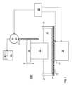
図1は、本発明の実施形態に従って構成された3D印刷システム100の断面を示し、3D印刷システム100では、物体(例えば、3D物体)22を製造するために、光硬化液体樹脂(典型的には、液体ポリマ)18を硬化させる電磁放射線(例えば、UV光)が使用される。物体22は、1層ずつ製造され(即ち、物体22の新しい層が、物体22の底面に隣接した液体ポリマ18の層を光硬化させることによって形成され)、新しい層を形成するとき、物体を造形プレート20によって上昇させ、光硬化液体樹脂18の次の層が、新しく形成された層の下に引かれることを可能にする。追加の層を形成するこのプロセスを、物体の製造が完了するまで、多数回繰返す。 FIG. 1 illustrates a cross-section of a
3D印刷システム100は、光硬化液体樹脂18を収容するためのタンク10を含む。タンク10の底部(又は、タンク10の少なくとも一部分)は、可撓性膜14によってシールされ(即ち、光硬化液体ポリマ18がタンク10の外に漏れることを防止し)、可撓性膜14は、光源26からの電磁放射線がタンク10内に入ることを可能にするために、樹脂を硬化させるのに興味のある波長において透明である(又は、ほぼ透明である)。液体樹脂の選択的な硬化を可能にする(3D物体を所望の形状/パターンに製造することを可能にする)マスク24(例えば、液晶層)が、光源26と光硬化液体樹脂18の間に配置される。種々の実施形態において、レンズ、反射器、フィルタ、及び/又はフィルム等のコリメーション要素及び発散要素が、マスク24と光源26の間に位置決めされてもよい。これらの要素は、図面を不必要に不明瞭にしないために、図示していない。
ホウケイ酸塩ガラス又はその他の材料で形成されたプラテン又はバッキング部材16が、マスク24と可撓性膜14の間に配置され、構造的支持部を構成する。プラテンはまた、樹脂を硬化させるのに興味のある1つ又は2つ以上の波長において透明である(又は、ほぼ透明である)。他の例では、プラテン16は、金属またはプラスチックであり、光源26からの電磁放射線がタンク10内に入ることを可能にする透明窓を含んでいてもよい。他の実施形態では、マスク24自体が、別体の窓の代わりに使用され、その周囲がガスケットでシールされてもよい。マスク24、プラテン16、及び可撓性膜14を、ある距離だけ互いから離れて配置されるように示されているけれども、実際には、これらの構成要素が互いに接触し、任意の空気インタフェースにおける屈折を防止するように位置決めされるのがよいことに注目すべきである。可撓性膜14は、タンクの縁又はその他の開口のところで液密な周囲部を維持するように(「液密な」は、通常の使用中にタンクが漏れないことを意味する。)、タンク10の縁又は交換式カートリッジ組立体(図示せず)に固着される。 A platen or
3D印刷システム100を使用して、物体22の1つの層を製造するとき、電磁放射線を放射線源26から放射させ、マスク24、プラテン16、及び可撓性膜14を通過させてタンク10内に到達させる。電磁放射線は、物体22の底部に隣接した画像平面上に画像を形成する。画像内の高(又は中)強度の領域により、光硬化液体樹脂18の局所領域を硬化させる。新しく硬化させた層は、物体22の以前の底面に接着するが、可撓性膜14の存在により、タンク10の底面に実質的に接着しない。新しく硬化させた層が形成された後、造形プレート20をタンクの底部から遠ざかるように上昇させる間、電磁放射線の放射を一時的に中断するのがよく(又は「連続印刷」の場合にはそうしない)、そのようにして、物体22の別の新しい層を印刷する。 When
造形プレート20は、リードスクリュー12又はその他の構成を駆動するモータ(M)30の作動によって、上昇したり下降したりする。モータシャフトの回転によるリードスクリュー12の回転により、造形プレート20をタンク10の底部に対して上昇させたり下降させたりする。別の実施形態では、線形アクチュエータ又はその他の構成を、造形プレート20を上昇させたり下降させたりするのに使用してもよい。 The
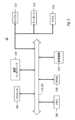
印刷プロセスの幾つかの側面は、プロセッサベースのシステムとして実施されるコントローラ28によって指図され、コントローラ28は、プロセッサが実行可能な命令を記憶し且つプロセッサが読取り可能である記憶媒体を有し、その結果、プロセッサがこれらの命令を実行すると、プロセッサは、上述した動作を生じさせるオペレーションを実行する。例えば、特にコントローラ28は、モータ30による造形プレート20の上昇/下降、光源26の作動及び非作動、及びマスク24を介する製造における物体の断面画像の投影を指示する。図2は、かかるコントローラ28の例を提供するが、かかるコントローラの全てがコントローラ28の全ての特徴を有している必要はない。例えば、表示機能がコントローラに通信可能に接続されたクライアントのコンピュータによって提供されれば、又は、表示機能が必要なければ、幾つかのコントローラは、ディスプレイを含んでいなくてもよい。かかる詳細は、本発明に重要ではない。 Aspects of the printing process are directed by a
コントローラ28は、情報を伝達するためのバス202又はその他の伝達機構と、情報を処理するためにバス202と接続されたプロセッサ204(例えば、マイクロプロセッサ)を含む。コントローラ28はまた、情報及びプロセッサ204によって実行すべき命令(例えば、Gコード)を記憶するためにバス202に接続されたメインメモリ206、例えば、ランダムアクセスメモリ(RAM)又はその他の動的記憶装置を含む。メインメモリ206はまた、プロセッサ204によって実行すべき命令の実行中、一時的な変数又はその他の中間情報を記憶するのに使用されてもよい。コントローラ28は更に、静的情報及びプロセッサ204のための命令を記憶するためにバス202に接続されたリードオンリーメモリ(ROM)208又はその他の静的記憶装置を含む。記憶装置210、例えば、ハードディスク、フラッシュメモリベースの記憶媒体、又はプロセッサ204が読取ることができるその他の記憶媒体が設けられ、情報及び命令(例えば、オペレーティングシステム、スライサーアプリケーション等のアプリケーションプログラム等)を記憶するためにバス202に接続される。
コントローラ28は、情報をコンピュータのユーザに表示するために、ディスプレイ212、例えば、フラットパネルディスプレイにバス202を介して接続される。情報及び命令の選択をプロセッサ204に伝達するための入力装置214が、バス202に接続され、入力装置214は、例えば、英数字キー及びその他のキーを含むキーボードである。別の種類のユーザ入力装置は、命令情報及び命令の選択をプロセッサ204に伝達したり、ディスプレイ212上のカーソルの移動を制御したりするカーソル制御装置216であり、カーソル制御装置216は、例えば、マウス、トラックパッド、又はそれと同様の入力装置である。その他のユーザインタフェース装置、例えば、マイクロフォン、スピーカー等は、詳細には図示されていないが、ユーザの入力の受入れ及び/又は出力の呈示と関連していてもよい。
コントローラ28はまた、バス202に接続された通信インタフェース218を含む。通信インタフェース218は、上述した種々のコンピュータシステムへの接続及びかかるコンピュータシステム内での接続を提供するコンピュータネットワークとの双方向データ通信チャネルを構成するのがよい。例えば、通信インタフェース218は、互換性のあるLANへのデータ通信接続を提供するローカルエリアネットワーク(LAN)カードであり、LAN自体は、1つ又は2つ以上のインターネットサービスプロバイダーネットワークを介してインターネットに通信接続されている。かかる通信経路の正確な詳細は、本発明に重要ではない。重要なことは、コントローラ28がメッセージ及びデータ、例えば、プリンタ100を使用して生産すべき3D物品を表現するデジタルファイルを、通信インタフェース218を介して送信及び受信できること、及び、このようにインターネットを通じてアクセス可能なホストと通信することである。コントローラ28の構成要素は、単一の装置内に配置されていてもよいし、物理的及び/又は地理的に離れた複数の装置内に配置されていてもよいことに注意すべきである。
本発明の側面によれば、印刷システム100を使用して造形プロセスを開始する前に、タンク10を樹脂で充填し、造形プレート20を樹脂の中に下降させる。コントローラ28は、モータ30を作動させ、造形プレート20を樹脂内で上昇させ、造形プレートを上昇させるのに必要とされるトルクを、トルクメータ32によって記録する。1つの実施形態では、トルクメータ32は、モータ30と一体であり、トルクを電気信号に変換するセンサ又はトランスデューサを含む。センサは、例えば、リードスクリュー12と一直線に配置された回転トルクセンサであり、かかる回転トルクセンサは、造形プレート20を樹脂内で移動させるためにリードスクリューを回転させるのに必要とされるトルクの直接的な測定値を提供する。光トルクセンサ又は表面音響波(SAW)トルクセンサは、この適用例に非常に適した2つの種類のセンサである。他の実施形態では、トルクメータは、コントローラ38の1つの機能であってもよいし、独立型ユニットであってもよく、独立型ユニットは、コントローラ38のように、プロセッサベースであり、メモリ又はその他の記憶装置に記憶され且つプロセッサが実行可能な命令の制御の下で作動する。 According to aspects of the present invention, prior to beginning a build process using
造形プレートを樹脂内で移動させるのに必要とされるトルクは、樹脂の粘度に比例する。低粘度樹脂には、比較的小さいトルクしか必要とされないが、高粘度樹脂には、比較的大きいトルクが必要とされる。トルクモータ及び造形プレートの所定の組合せに必要とされる絶対トルクを、既知の粘度の様々な樹脂について決定し、一覧にしておくのがよい。一覧にした結果を、表の形態で、例えば、コントローラ28又はトルクメータ32の不揮発性メモリ内に記憶するのがよい。この場合、造形プロセスの前に、造形プレート20を樹脂内で上昇させるためにコントローラ28がモータ30を作動させるとき、造形プレートを上昇させるのに必要とされる測定されたトルクを、タンク10内の樹脂の粘度を決定するための表を検索するのに使用するのがよい。測定されたトルクが、一覧にされた樹脂の粘度の2つの値の間にあれば、測定されたトルクに最も近い粘度の値を提供してもよいし、測定されたトルクに関して内挿した粘度の値を提供してもよい。 The torque required to move the build plate through the resin is proportional to the viscosity of the resin. Low viscosity resins require relatively low torque, while high viscosity resins require relatively high torque. The absolute torque required for a given combination of torque motor and build plate should be determined and tabulated for various resins of known viscosity. The tabulated results may be stored in tabular form, for example, in non-volatile memory of
造形プロセスの間、同様のプロセスを使用してもよい。即ち、定期的に又はその他の所望の時間ごとに、上述したルックアップテーブル手順を使用して、樹脂の粘度を決定してもよい。造形プロセス中の樹脂は、光源26からのUV光に露出される理由で加熱されるので、造形プロセスの間、樹脂の粘度が変化することが非常に起こり得る。光重合プロセスは、発熱性であり、熱を生成し、この熱は、バット内の樹脂全体に(必ずしも一様にではないけれども)伝達される。幾つかの実施形態では、樹脂循環システム、例えば、本発明の譲受人に譲渡されている米国特許出願第16/676,940号に開示されている樹脂循環システムを、樹脂の温度を造形プロセス全体にわたって比較的一定に維持するために採用してもよい。 A similar process may be used during the molding process. That is, the viscosity of the resin may be determined using the lookup table procedure described above, periodically or at any other desired time. Since the resin during the build process is heated due to exposure to UV light from the
造形プロセスの前、樹脂の所望の粘度を達成するために、樹脂の温度を変化させるのがよい。例えば、上で参照した特許出願に開示されている樹脂循環システムを、かかる目的のために使用してもよい。変形例として、マスク24を暗状態に維持しながら光源26を作動させることによって、樹脂を加熱してもよい。この暗状態は、樹脂を硬化させるUV光がタンク10内に入射しないことが必要とされる。光源26及びマスク24自体からの熱は、タンク内の樹脂に伝達され、樹脂が温まると、その粘度が変化する。造形プレートを樹脂の中で移動させるために必要とされるトルクを測定することを介して樹脂の粘度を測定する上述した手順を、この加熱プロセス中、造形プロセスを開始することを可能にする所望の粘度に達するまで使用するのがよい。 Prior to the molding process, the temperature of the resin may be varied to achieve the desired viscosity of the resin. For example, the resin circulation systems disclosed in the above-referenced patent applications may be used for such purposes. Alternatively, the resin may be heated by activating
樹脂の粘度を決定するためにトルクを使用することに関する例示として、造形プレートを樹脂の中で上昇させたり下降させたりするのに必要とされるトルクは、
トルク = 力×(長さ×sin(角度))
のように表現され、ここで、「長さ」は、リードスクリューの上下方向移動距離であり、「角度」は、リードスクリューが特定された「長さ」にわたって駆動される間の回転角度であり、「長さ」及び「角度」の各々を測定するのがよい。上述したように、トルクを、トルクメータによって提供された測定値から決定するのがよく、かくして、「力」は、
力 = (長さ×sin(角度))/トルク
のように決定される。As an illustration of using torque to determine resin viscosity, the torque required to raise and lower the build plate through the resin is:
Torque = force x (length x sin (angle))
where "length" is the vertical travel distance of the lead screw and "angle" is the angle of rotation during which the lead screw is driven over the specified "length" , "length" and "angle" should each be measured. As noted above, torque may be determined from measurements provided by a torque meter, thus "force" is
It is determined as force = (length x sin(angle))/torque.
この「力」を、造形プレートを樹脂の中で上昇/下降させたときに経験する抗力とみなすのがよい。抗力(FD)は、
FD = 1/2×ρv2CDA
のように、樹脂の密度(ρ)に関連する。ここで、vは、樹脂(本発明の目的のために、造形プレートの移動中、静止しているものとみなす)に対する造形プレートの速度であり、「A」は、造形プレートの断面積であり、CDは、樹脂の無次元抗力係数である。樹脂の密度は、通常、その製造者から入手可能であり、典型的には、1.05~1.25g/cm3の範囲内にある。異なるプリンタのための個々の造形プレートの抗力係数を、異なる樹脂ごとに実験的に決定し、使用のために一覧にするのがよい。更に、特定のアスペクト比(長さ:深さ)を有する矩形で平らなプレートに共通の抗力係数が、種々の商業的刊行物内で利用されており、一般的には、1.5~2の間で変化する。特定の造形プレートのための決定された抗力係数がない場合、造形プレートが滑らかな矩形表面を有することを仮定すれば、1.8の値を良好な近似値として使用してもよい。樹脂の密度は、温度によって変化するので、種々の造形プレートと樹脂の組合せのための抗力係数を一覧にすることを求めるとき、作動環境に似せた温度スペクトル全体の抗力の測定を実行するべきである。It is best to think of this "force" as the drag experienced when the build plate is raised/lowered through the resin. The drag force (FD ) is
FD = 1/2×ρv2 CD A
is related to the density (ρ) of the resin as where v is the velocity of the build plate relative to the resin (which for the purposes of this invention is considered stationary during movement of the build plate) and "A" is the cross-sectional area of the build plate. , CD is the dimensionless drag coefficient of the resin. Resin densities are commonly available from their manufacturers and are typically in the range of 1.05 to 1.25 g/cm3 . The drag coefficient of individual build plates for different printers should be experimentally determined for different resins and tabulated for use. In addition, drag coefficients common to rectangular flat plates with specific aspect ratios (length:depth) are available in various commercial publications, typically between 1.5 and 2 varies between In the absence of a determined drag coefficient for a particular build plate, a value of 1.8 may be used as a good approximation, assuming the build plate has a smooth rectangular surface. Resin density varies with temperature, so when seeking to tabulate drag coefficients for various build plate and resin combinations, drag measurements should be performed across the temperature spectrum to simulate the operating environment. be.
低速度において、樹脂を非圧縮性流体として取扱うとき、3D印刷適用例において予想されるように、移動している造形プレートを越える樹脂の流れを、層流又はほぼ層流であると仮定する。更に、(もし存在すれば)製造中の物体に対する造形プレートの寸法は、支配的であると仮定する。したがって、(物体の製造中でさえも)抗力は、
FD = aηv
のように、樹脂の粘度(η)に関係する。ここで、「a」は、造形プレートの「寸法」であり、「v」は、造形プレートを樹脂の中で上昇/下降させたときの造形プレートの速度である。所定の造形プレートの「寸法」を、実験的に決定するのがよい。例えば、所定のプリンタ/造形プレート/樹脂の組合せについて、抗力を、上で特定したように、測定されたトルクから計算する。樹脂の製造者は、普通、基準温度、典型的には25℃における樹脂の粘度を特定する。かくして、この樹脂におけるトルクの測定値をその基準温度で取っていれば、造形プレートの「寸法」を
a = FD/ηv = ρvCDA/2η
のように計算するのがよい。上述したように、この寸法は、印刷作業中、共通の物体組立体にわたって不変であるとみなされ、したがって、異なる温度のための異なる粘度の値をトルクの関数として一覧にすることを可能にする。At low velocities and treating the resin as an incompressible fluid, we assume that the flow of the resin over the moving build plate is laminar or nearly laminar, as expected in 3D printing applications. Further, it is assumed that the dimensions of the build plate (if any) relative to the object being manufactured are dominant. Therefore, the drag force (even during the manufacture of the object) is
FD = aηv
is related to the viscosity (η) of the resin. where "a" is the "dimension" of the build plate and "v" is the velocity of the build plate as it is raised/lowered through the resin. The "dimensions" of a given build plate may be determined experimentally. For example, for a given printer/build plate/resin combination, the drag force is calculated from the measured torque, as specified above. Resin manufacturers usually specify the viscosity of the resin at a reference temperature, typically 25°C. Thus, if the torque measurement in this resin is taken at its reference temperature, the "dimensions" of the build plate are a = FD /ηv = ρvCD A/2η
It is better to calculate as As noted above, this dimension is assumed to be invariant across common object assemblies during a printing run, thus allowing different viscosity values for different temperatures to be listed as a function of torque. .
かくして、バット重合プリンタに使用される光硬化樹脂の粘度を決定する方法及びシステムを記載した。 Thus, a method and system for determining the viscosity of photocurable resins used in vat polymerization printers has been described.
Claims (17)
Translated fromJapaneseバット光重合プリンタ(100)を使用する造形プロセスを開始する前に、バット光重合プリンタ(100)のタンク(10)を樹脂(18)で充填し、バット光重合プリンタ(100)の造形プレート(20)を樹脂(18)の中に下降させることと、
造形プレート(20)を樹脂(18)内で上昇させるようにモータ(30)を作動させ、造形プレート(20)を上昇させるのに必要とされるトルクの測定値をトルクメータ(32)によって記録することと、
トルクの測定値を使用して、バット光重合プリンタ(100)のタンク(10)内の樹脂(18)の粘度を決定するために、樹脂の既知の粘度におけるトルクの測定値を一覧にした表を検索することと、を含む方法。A method for determining the viscosity of a photocurable resin (18) used in a vat photopolymerization printer (100) comprising:
Prior to starting the build process using the vat photopolymerization printer (100), the tank (10) of the vat photopolymerization printer (100) is filled with resin (18) and the build plate (18) of the vat photopolymerization printer (100) is 20) into the resin (18);
A motor (30) is actuated to raise the build plate (20) into the resin (18) and a torque meter (32) records a measurement of the torque required to raise the build plate (20). and
A table listing torque measurements at known viscosities of the resin to determine the viscosity of the resin (18) in the tank (10) of the vat photopolymerization printer (100) using the torque measurements. and a method comprising:
或る容量の樹脂(18)を保持するタンク(10)を有するバット光重合プリンタ(100)と、
タンク(10)内で上昇させたり下降させたりするように構成された造形プレート(20)と、
造形プレート(20)を上昇させる及び/又は下降させるのに結合されたモータ(30)と、
樹脂(18)内の造形プレート(20)を上昇させる及び/又は下降させるのに必要とされるトルクを測定するように構成されたトルクメータ(32)と、
コントローラ(28)と、を有し、
コントローラ(28)は、樹脂(18)内の造形プレート(20)を上昇させる及び/又は下降させるためにモータ(30)を作動させるように構成され、トルクメータ(32)からトルクの測定値を受取るように構成され、トルクの測定値を使用し、樹脂の既知の粘度におけるトルクの測定値を一覧にした表を検索することによって、バット光重合プリンタ(100)のタンク(10)内の樹脂(18)の粘度を決定するように構成される、システム。A system for determining the viscosity of a photocurable resin (18) used in a vat photopolymerization printer (100), comprising:
a vat photopolymerization printer (100) having a tank (10) holding a volume of resin (18);
a build plate (20) configured to be raised and lowered within the tank (10);
a motor (30) coupled to raise and/or lower the build plate (20);
a torque meter (32) configured to measure the torque required to raise and/or lower the build plate (20) in the resin (18);
a controller (28);
A controller (28) is configured to operate a motor (30) to raise and/or lower the build plate (20) within the resin (18) and obtains torque measurements from a torque meter (32). The resin in the tank (10) of the vat photopolymerization printer (100) configured to receive, using the torque measurements, by looking up a table listing the torque measurements at known viscosities of the resin. A system configured to determine the viscosity of (18).
Applications Claiming Priority (3)
| Application Number | Priority Date | Filing Date | Title |
|---|---|---|---|
| US201962941653P | 2019-11-27 | 2019-11-27 | |
| US62/941,653 | 2019-11-27 | ||
| PCT/US2020/061382WO2021108228A1 (en) | 2019-11-27 | 2020-11-19 | Methods and systems for determining viscosity of photo-curing resin for vat photopolymerization printer |
Publications (1)
| Publication Number | Publication Date |
|---|---|
| JP2023503958Atrue JP2023503958A (en) | 2023-02-01 |
Family
ID=73856285
Family Applications (1)
| Application Number | Title | Priority Date | Filing Date |
|---|---|---|---|
| JP2022530298APendingJP2023503958A (en) | 2019-11-27 | 2020-11-19 | Method and system for determining viscosity of photocuring resin for vat photopolymerization printer |
Country Status (6)
| Country | Link |
|---|---|
| US (1) | US11169067B2 (en) |
| EP (1) | EP4065343B1 (en) |
| JP (1) | JP2023503958A (en) |
| KR (1) | KR20220108776A (en) |
| CN (1) | CN114746249B (en) |
| WO (1) | WO2021108228A1 (en) |
Families Citing this family (8)
| Publication number | Priority date | Publication date | Assignee | Title |
|---|---|---|---|---|
| US11235533B2 (en)* | 2019-04-26 | 2022-02-01 | Carbon, Inc. | Resin viscosity detection in additive manufacturing |
| US11707883B2 (en) | 2020-11-20 | 2023-07-25 | General Electric Company | Foil interaction device for additive manufacturing |
| WO2022125881A1 (en) | 2020-12-11 | 2022-06-16 | Carbon, Inc. | Force-regulated additive manufacturing |
| US11865780B2 (en) | 2021-02-26 | 2024-01-09 | General Electric Company | Accumalator assembly for additive manufacturing |
| US11826950B2 (en) | 2021-07-09 | 2023-11-28 | General Electric Company | Resin management system for additive manufacturing |
| US11813799B2 (en) | 2021-09-01 | 2023-11-14 | General Electric Company | Control systems and methods for additive manufacturing |
| US11858199B2 (en)* | 2021-10-18 | 2024-01-02 | NEXA3D Inc. | Methods and systems for photocuring liquid with reduced heat generation using a digital light processing (DLP) light source |
| WO2023183392A1 (en)* | 2022-03-22 | 2023-09-28 | Nano-Dimension Technologies, Ltd. | Systems and methods for controlling additive manufacturing |
Family Cites Families (10)
| Publication number | Priority date | Publication date | Assignee | Title |
|---|---|---|---|---|
| US9360757B2 (en)* | 2013-08-14 | 2016-06-07 | Carbon3D, Inc. | Continuous liquid interphase printing |
| AT515138B1 (en) | 2013-11-22 | 2016-05-15 | Univ Wien Tech | Apparatus for processing photopolymerizable material for the layered construction of a shaped body |
| EP3023226B1 (en) | 2014-11-19 | 2017-02-08 | Ivoclar Vivadent AG | Stereolithography device with a heating device |
| FI129702B (en)* | 2015-10-09 | 2022-07-15 | Inkron Ltd | Material for three-dimensional printing and method for producing a 3D-printed product |
| CA3024147A1 (en)* | 2016-05-31 | 2017-12-07 | Northwestern University | Method for the fabrication of three-dimensional objects and apparatus for same |
| EP3284583B1 (en) | 2016-08-18 | 2019-02-20 | Cubicure GmbH | Method and device for lithography-based generative production of three-dimensional moulds |
| US11203156B2 (en) | 2018-08-20 | 2021-12-21 | NEXA3D Inc. | Methods and systems for photo-curing photo-sensitive material for printing and other applications |
| CA3129247A1 (en) | 2018-11-09 | 2020-05-14 | NEXA3D Inc. | Three-dimensional printing system |
| US11235533B2 (en)* | 2019-04-26 | 2022-02-01 | Carbon, Inc. | Resin viscosity detection in additive manufacturing |
| US11376798B2 (en)* | 2019-08-02 | 2022-07-05 | Stratasys, Inc. | Method for interlayer feedback control and failure prevention in an additive manufacturing process |
- 2020
- 2020-11-19JPJP2022530298Apatent/JP2023503958A/enactivePending
- 2020-11-19WOPCT/US2020/061382patent/WO2021108228A1/ennot_activeCeased
- 2020-11-19KRKR1020227018264Apatent/KR20220108776A/enactivePending
- 2020-11-19CNCN202080082136.5Apatent/CN114746249B/enactiveActive
- 2020-11-19USUS16/949,905patent/US11169067B2/enactiveActive
- 2020-11-19EPEP20828395.2Apatent/EP4065343B1/enactiveActive
Also Published As
| Publication number | Publication date |
|---|---|
| CN114746249A (en) | 2022-07-12 |
| KR20220108776A (en) | 2022-08-03 |
| EP4065343B1 (en) | 2024-01-17 |
| EP4065343C0 (en) | 2024-01-17 |
| EP4065343A1 (en) | 2022-10-05 |
| WO2021108228A1 (en) | 2021-06-03 |
| US11169067B2 (en) | 2021-11-09 |
| CN114746249B (en) | 2024-03-29 |
| US20210156779A1 (en) | 2021-05-27 |
Similar Documents
| Publication | Publication Date | Title |
|---|---|---|
| JP2023503958A (en) | Method and system for determining viscosity of photocuring resin for vat photopolymerization printer | |
| KR102225135B1 (en) | Three-dimensional manufacturing apparatus, three-dimensional manufactured object producing method, and container for three-dimensional manufacturing apparatus | |
| Pan et al. | Study of separation force in constrained surface projection stereolithography | |
| Hopkins et al. | Energy consumption of common desktop additive manufacturing technologies | |
| EP1025982B1 (en) | Method and apparatus for stereolithographically forming three dimensional objects with reduced distortion | |
| EP2996852B1 (en) | Apparatus for fabrication of three dimensional objects | |
| TW201637824A (en) | Additive manufacturing device with release mechanism | |
| CN112888551A (en) | Method and system for photocuring of photosensitive materials for printing and other applications | |
| CN113498382A (en) | Method and system for manufacturing optical volume elements from curable materials using additive manufacturing techniques | |
| Heidt et al. | The liberalization of microfluidics: Form 2 benchtop 3D printing as an affordable alternative to established manufacturing methods | |
| CN106042388A (en) | 3D printing device and its system control method and its working method | |
| PL234153B1 (en) | Printer for spatial printing | |
| US6153142A (en) | Stereolithographic method and apparatus for production of three dimensional objects with enhanced thermal control of the build environment | |
| JP2020508234A (en) | How to refill 3D printer resin | |
| CN115230163A (en) | A fast DLP 3D printing control parameter optimization method combining continuous and layered molding | |
| CN114008619A (en) | Method and system for outputting a manufacturing document for producing an optical element | |
| KR102416785B1 (en) | Three dimensional printer and driving method thereof | |
| La et al. | Numerical and experimental investigation of plastic injection molding of micro‐engineered surfaces | |
| Reid et al. | Impact of beam shape on print accuracy in digital light processing additive manufacture | |
| Choi et al. | Fluid Driven Membrane Actuation for Reconfigurable Acoustic Manipulation | |
| US20210060865A1 (en) | Mutliphysics model for inverse warping of data file in preparation for additive manufacturing | |
| CN205836030U (en) | Quick 3D printing equipment based on liquid Stereolithography | |
| Manizani et al. | Investigating the Effect of Separation Speed and Image Cross-Section Geometry on The Separation Force in DLP Method using FEP and PP Polymer Membranes. | |
| Chakraborty et al. | Decreasing the shear stress-induced in-plane molecular alignment by unprecedented stereolithographic delay in three-dimensional printing | |
| JPWO2019124526A1 (en) | Stereolithography equipment, stereolithography program and stereolithography method |
Legal Events
| Date | Code | Title | Description |
|---|---|---|---|
| A621 | Written request for application examination | Free format text:JAPANESE INTERMEDIATE CODE: A621 Effective date:20231117 | |
| A977 | Report on retrieval | Free format text:JAPANESE INTERMEDIATE CODE: A971007 Effective date:20241016 | |
| A131 | Notification of reasons for refusal | Free format text:JAPANESE INTERMEDIATE CODE: A131 Effective date:20241021 | |
| A02 | Decision of refusal | Free format text:JAPANESE INTERMEDIATE CODE: A02 Effective date:20250410 |