JP2023502003A - tubular tissue deformer - Google Patents
tubular tissue deformerDownload PDFInfo
- Publication number
- JP2023502003A JP2023502003AJP2022526439AJP2022526439AJP2023502003AJP 2023502003 AJP2023502003 AJP 2023502003AJP 2022526439 AJP2022526439 AJP 2022526439AJP 2022526439 AJP2022526439 AJP 2022526439AJP 2023502003 AJP2023502003 AJP 2023502003A
- Authority
- JP
- Japan
- Prior art keywords
- tubular tissue
- ttt
- tissue structure
- bushing
- leaves
- Prior art date
- Legal status (The legal status is an assumption and is not a legal conclusion. Google has not performed a legal analysis and makes no representation as to the accuracy of the status listed.)
- Pending
Links
Images


Classifications
- A—HUMAN NECESSITIES
- A61—MEDICAL OR VETERINARY SCIENCE; HYGIENE
- A61B—DIAGNOSIS; SURGERY; IDENTIFICATION
- A61B17/00—Surgical instruments, devices or methods
- A61B17/11—Surgical instruments, devices or methods for performing anastomosis; Buttons for anastomosis
- A—HUMAN NECESSITIES
- A61—MEDICAL OR VETERINARY SCIENCE; HYGIENE
- A61B—DIAGNOSIS; SURGERY; IDENTIFICATION
- A61B17/00—Surgical instruments, devices or methods
- A61B17/30—Surgical pincettes, i.e. surgical tweezers without pivotal connections
- A—HUMAN NECESSITIES
- A61—MEDICAL OR VETERINARY SCIENCE; HYGIENE
- A61B—DIAGNOSIS; SURGERY; IDENTIFICATION
- A61B17/00—Surgical instruments, devices or methods
- A61B17/11—Surgical instruments, devices or methods for performing anastomosis; Buttons for anastomosis
- A61B17/1114—Surgical instruments, devices or methods for performing anastomosis; Buttons for anastomosis of the digestive tract, e.g. bowels or oesophagus
- A—HUMAN NECESSITIES
- A61—MEDICAL OR VETERINARY SCIENCE; HYGIENE
- A61B—DIAGNOSIS; SURGERY; IDENTIFICATION
- A61B17/00—Surgical instruments, devices or methods
- A61B2017/00831—Material properties
- A61B2017/00902—Material properties transparent or translucent
- A61B2017/00907—Material properties transparent or translucent for light
- A—HUMAN NECESSITIES
- A61—MEDICAL OR VETERINARY SCIENCE; HYGIENE
- A61B—DIAGNOSIS; SURGERY; IDENTIFICATION
- A61B17/00—Surgical instruments, devices or methods
- A61B17/11—Surgical instruments, devices or methods for performing anastomosis; Buttons for anastomosis
- A61B2017/1107—Surgical instruments, devices or methods for performing anastomosis; Buttons for anastomosis for blood vessels
- A—HUMAN NECESSITIES
- A61—MEDICAL OR VETERINARY SCIENCE; HYGIENE
- A61B—DIAGNOSIS; SURGERY; IDENTIFICATION
- A61B17/00—Surgical instruments, devices or methods
- A61B17/11—Surgical instruments, devices or methods for performing anastomosis; Buttons for anastomosis
- A61B2017/1121—Surgical instruments, devices or methods for performing anastomosis; Buttons for anastomosis adapted for performing tissue or graft eversion
- A—HUMAN NECESSITIES
- A61—MEDICAL OR VETERINARY SCIENCE; HYGIENE
- A61B—DIAGNOSIS; SURGERY; IDENTIFICATION
- A61B17/00—Surgical instruments, devices or methods
- A61B17/11—Surgical instruments, devices or methods for performing anastomosis; Buttons for anastomosis
- A61B2017/1132—End-to-end connections
- A—HUMAN NECESSITIES
- A61—MEDICAL OR VETERINARY SCIENCE; HYGIENE
- A61B—DIAGNOSIS; SURGERY; IDENTIFICATION
- A61B17/00—Surgical instruments, devices or methods
- A61B17/30—Surgical pincettes, i.e. surgical tweezers without pivotal connections
- A61B2017/306—Surgical pincettes, i.e. surgical tweezers without pivotal connections holding by means of suction
Landscapes
- Health & Medical Sciences (AREA)
- Life Sciences & Earth Sciences (AREA)
- Surgery (AREA)
- Molecular Biology (AREA)
- Engineering & Computer Science (AREA)
- Biomedical Technology (AREA)
- Heart & Thoracic Surgery (AREA)
- Medical Informatics (AREA)
- Nuclear Medicine, Radiotherapy & Molecular Imaging (AREA)
- Animal Behavior & Ethology (AREA)
- General Health & Medical Sciences (AREA)
- Public Health (AREA)
- Veterinary Medicine (AREA)
- Surgical Instruments (AREA)
- Physiology (AREA)
- Prostheses (AREA)
Abstract
Translated fromJapanese
Description
Translated fromJapanese本発明は、全般的には、管状組織構造用の管状組織変形器ならびに関連する用具および方法に関する。 The present invention relates generally to tubular tissue deformers for tubular tissue structures and related tools and methods.
外科手術において、組織構造は、吻合を形成するために結合され得る。従来、これは、組織構造を手で縫合することが必要であり、この縫合は、時間がかかり、危険を伴い、要求が厳しいものであり、広範な訓練および高い精度を必要とし得る。 In surgery, tissue structures may be joined to form an anastomosis. Traditionally, this requires hand suturing of tissue structures, which can be time consuming, risky, demanding, and require extensive training and high precision.
組織構造の結合を補助するための装置は、1つずつ組織構造に付着される大きな固定ピンによって組織構造を保持し得る。しかしながら、いくつかの組織構造は、それらのピンへの付着に伴う歪みを受けた場合に、裂ける場合がある。これは、動脈のような比較的厚壁の組織構造または柔軟性のない組織構造にとって特に問題となり得る。 A device for assisting in joining tissue structures may hold the tissue structures by means of large fixation pins that are attached to the tissue structures one by one. However, some tissue structures may tear when subjected to the strain associated with their attachment to the pins. This can be particularly problematic for relatively thick-walled or inflexible tissue structures such as arteries.
治癒のために組織構造の内側表面間の良好な接触を確実にするために、組織構造を互いに結合する前に外翻させ得る。いくつかの状況において、このことは、組織構造を過度に変形させ、吻合を妨げることによって、組織構造の損傷を引き起こし得る。これは、動脈のような比較的厚壁の組織構造または柔軟性のない組織構造にとって特に問題となり得る。いくつかの状況では、結合された組織構造の内側表面間の良好な接触を維持するために、適切な形状の表面を提供することが困難であり得る。 To ensure good contact between the inner surfaces of the tissue structures for healing, the tissue structures may be everted prior to bonding together. In some situations, this can cause damage to tissue structures by overly deforming them and preventing anastomosis. This can be particularly problematic for relatively thick-walled or inflexible tissue structures such as arteries. In some situations, it can be difficult to provide appropriately shaped surfaces to maintain good contact between the inner surfaces of the joined tissue structures.
1つの例示的な実施形態によれば、管状組織構造用の管状組織変形器であって、
複数のリーフと、
複数のリーフの各々の上の複数のリテーナであって、各々が管状組織構造をそれぞれのリーフ上で保持するように構成された複数のリテーナと
を備える管状組織変形器が提供される。According to one exemplary embodiment, a tubular tissue deformer for tubular tissue structures comprising:
a plurality of leaves;
A tubular tissue deformer is provided comprising a plurality of retainers on each of a plurality of leaves, each retainer configured to retain a tubular tissue structure on the respective leaf.
別の例示的な実施形態によれば、管状組織構造を管状組織変形器に付着させる方法であって、
管状組織構造の一部を押圧して、管状組織構造を複数の位置で同時に保持するステップを含む方法が提供される。According to another exemplary embodiment, a method of attaching a tubular tissue structure to a tubular tissue deformer comprising:
A method is provided that includes compressing a portion of a tubular tissue structure to simultaneously hold the tubular tissue structure at multiple locations.
別の例示的な実施形態によれば、管状組織構造用の管状組織変形器であって、
管状組織構造の外翻部分を保持するように構成された複数のリーフと、
第1の位置と第2の位置との間で移動可能であるように構成され、第2の位置にあるときに管状組織構造の外翻部分の外表面を支持するように構成されたブッシュと
を備える管状組織変形器が提供される。According to another exemplary embodiment, a tubular tissue deformer for tubular tissue structures comprising:
a plurality of leaves configured to hold everted portions of the tubular tissue structure;
a bushing configured to be movable between a first position and a second position and configured to support an outer surface of the everted portion of the tubular tissue structure when in the second position; A tubular tissue deformer is provided comprising:
別の例示的な実施形態によれば、
管状組織構造の一部を外翻させるステップと、
管状組織構造の外翻部分の外表面を、外翻部分の中心から離れるように外向きに湾曲する表面の上で支持するステップと
を含む方法が提供される。According to another exemplary embodiment,
everting a portion of the tubular tissue structure;
supporting the outer surface of the everting portion of the tubular tissue structure on a surface that curves outwardly away from the center of the everting portion.
別の例示的な実施形態によれば、管状組織変形器の開口部の周りにおいて管状組織変形器上で保持された管状組織構造の一部を拡径するための用具であって、
開口部に挿入して開口部を拡径し、そのことにより管状組織構造の一部を拡径するためのテーパ状部分を備える用具が提供される。According to another exemplary embodiment, a tool for expanding a portion of a tubular tissue structure retained on the tubular tissue deformer about an opening of the tubular tissue deformer, comprising:
A tool is provided having a tapered portion for insertion into an opening to expand the opening and thereby expand a portion of the tubular tissue structure.
別の例示的な実施形態によれば、管状組織変形器の開口部の周りにおいて管状組織変形器上で保持された管状組織構造の一部を拡径するための用具であって、
開口部に挿入して、開口部内で拡張して開口部を拡径し、そのことにより管状組織構造の一部を拡径するための拡張可能部分を備える用具が提供される。According to another exemplary embodiment, a tool for expanding a portion of a tubular tissue structure retained on the tubular tissue deformer about an opening of the tubular tissue deformer, comprising:
A tool is provided that includes an expandable portion for insertion into an opening and expanding within the opening to widen the opening, thereby widening a portion of the tubular tissue structure.
別の例示的な実施形態によれば、管状組織構造の一部を拡径する方法であって、
管状組織構造の一部を第1の直径で保持するステップと、
管状組織構造の一部が保持されている間に、管状組織構造の一部を第1の直径よりも大きい第2の直径に変形させるステップと、
第2の直径を有する前記管状組織構造の一部を保持するステップと
を含む方法が提供される。According to another exemplary embodiment, a method of radially expanding a portion of a tubular tissue structure, comprising:
holding a portion of the tubular tissue structure at a first diameter;
deforming a portion of the tubular tissue structure to a second diameter greater than the first diameter while the portion of the tubular tissue structure is held;
holding a portion of said tubular tissue structure having a second diameter.
別の例示的な実施形態によれば、管状組織構造用の管状組織変形器であり、
管状組織変形器の通路の周囲に位置決めされ、前記管状組織構造の一部を保持するように構成された1つまたは複数のリーフと、
通路内に少なくとも部分的に配置可能であるように構成されたブッシュと
を備える管状組織変形器であって、
ブッシュは、1つまたは複数のリーフを半径方向に拡張し、リーフを半径方向拡張状態に保持するように、少なくとも部分的に塑性変形可能である、管状組織変形器が提供される。According to another exemplary embodiment, a tubular tissue deformer for tubular tissue structures, comprising:
one or more leaves positioned around a passageway of the tubular tissue deformer and configured to retain a portion of the tubular tissue structure;
a bushing configured to be at least partially positionable within the passageway, the tubular tissue deformer comprising:
A tubular tissue deformer is provided wherein the bushing is at least partially plastically deformable to radially expand one or more of the leaves and retain the leaves in a radially expanded state.
別の例示的な実施形態によれば、管状組織構造を結合するためのシステムであり、
管状組織構造の一部を保持するための1つまたは複数のリテーナを有する第1の管状組織変形器であって、1つまたは複数のリテーナは管状組織構造の保持部分の周りの1つまたは複数のリテーナ位置に位置決めされる、第1の管状組織変形器と、
管状組織構造の一部を保持するための1つまたは複数のリテーナを有する第2の管状組織変形器であって、1つまたは複数のリテーナは管状組織構造の保持部分の周りの1つまたは複数のリテーナ位置に位置決めされる、第2の管状組織変形器と、
第1の結合装置と、
第1の結合装置に結合するように構成された第2の結合装置と
を備えるシステムであって、
第1の結合装置および第2の結合装置は、管状構造の保持部分を結合し、第1の管状組織変形器の1つまたは複数のリテーナ位置と第2の管状組織変形器の1つまたは複数のリテーナ位置との間の所定の回転オフセットを維持するように構成され、
回転オフセットは、保持部分が結合されるときに結合装置を通る長手方向軸を中心とするオフセットである、システムが提供される。According to another exemplary embodiment, a system for joining tubular tissue structures, comprising:
A first tubular tissue deformer having one or more retainers for retaining a portion of the tubular tissue structure, the one or more retainers being one or more around the retaining portion of the tubular tissue structure. a first tubular tissue deformer positioned at the retainer position of
A second tubular tissue deformer having one or more retainers for retaining a portion of the tubular tissue structure, the one or more retainers being one or more around the retaining portion of the tubular tissue structure. a second tubular tissue deformer positioned at the retainer position of
a first coupling device;
a second coupling device configured to couple to the first coupling device, comprising:
A first coupling device and a second coupling device couple the retaining portion of the tubular structure to one or more retainer positions of the first tubular tissue deformer and one or more of the second tubular tissue deformer. configured to maintain a predetermined rotational offset between the retainer position of
A system is provided wherein the rotational offset is the offset about the longitudinal axis through the coupling device when the retaining portions are coupled.
別の例示的な実施形態によれば、
管状組織構造の一部を管状組織変形器の複数のリテーナに押し付けて、管状組織構造の一部を管状組織変形器に付着させるように構成された変形可能な表面を含む付着用具が提供される。According to another exemplary embodiment,
An attachment tool is provided that includes a deformable surface configured to press a portion of the tubular tissue structure against a plurality of retainers of the tubular tissue deformer to attach the portion of the tubular tissue structure to the tubular tissue deformer. .
実施形態は、従属請求項のいずれかに従って実装され得る。 Embodiments may be implemented according to any of the dependent claims.
「備える(comprise)、(comprises)、(comprising)」という用語は、様々な管轄下で、排他的または包含的意味を有するものであり得ることが認められている。本明細書の目的のために、および特に断りのない限り、これらの用語は、包括的な意味を有することが意図され、すなわち、これらの用語は、その使用が直接言及されている列挙構成部品、およびおそらく他の特定されていない構成部品または要素の包含を意味すると解釈される。 It is recognized that the terms "comprises, comprising" may, under various jurisdictions, have an exclusive or an inclusive meaning. For the purposes of this specification, and unless otherwise indicated, these terms are intended to have an inclusive meaning, i.e., they refer to the enumerated components whose use is directly referred to. , and possibly other unspecified components or elements.
本明細書における文献の言及は、それが先行技術であること、他の文献と有効に組み合わせ可能であること、またはそれが共通の一般知識の一部を形成することを認めるものではない。 The citation of a document herein is not an admission that it is prior art, that it can be usefully combined with other documents, or that it forms part of the common general knowledge.
本明細書に組み込まれ、その一部を構成する添付図面は、本発明の実施形態を示しており、上記の本発明の概要および下記の実施形態の詳細な説明と共に、本発明の原理を説明する役割を果たす。 BRIEF DESCRIPTION OF THE DRAWINGS The accompanying drawings, which are incorporated in and constitute a part of this specification, illustrate embodiments of the invention and, together with the general description of the invention given above and the detailed description of the embodiments given below, serve to explain the principles of the invention. play a role in
本出願は、リーフ、ブッシュ、およびリテーナを有する管状組織変形器(TTT)に関する。各リーフは、2つ以上のリテーナを有する。リテーナは、管状組織構造をリテーナに1つずつ付着させるのではなく、管状組織構造を2つ以上のリテーナに同時に付着させることを可能にし得る。このことにより、組織構造の付着が単純化され、迅速化され得る。 The present application relates to a tubular tissue deformer (TTT) having leaves, bushings and retainers. Each leaf has two or more retainers. The retainer may allow the tubular tissue structures to be attached to two or more retainers simultaneously, rather than attaching the tubular tissue structures to the retainer one by one. This may simplify and speed up attachment of tissue structures.
ブッシュはさらに、リーフを拡張することによって組織構造を外翻させ、外翻した組織構造の外表面を支持するように設計される。このことは、別の組織構造に結合するための組織構造の大きく良好に支持された表面を提供し得、外翻時の組織構造の損傷を低減し得る。 The bushing is further designed to evert the tissue structure by expanding the leaf and to support the outer surface of the everted tissue structure. This may provide a large, well-supported surface of the tissue structure for attachment to another tissue structure, and may reduce damage to the tissue structure during eversion.
本出願はさらに、組織構造の付着を補助し、組織構造を拡径するための用具および方法、ならびに管状組織変形器と管状組織構造とを結合するためのシステムに関する。 The present application further relates to tools and methods for aiding attachment and expansion of tissue structures, and systems for coupling tubular tissue deformers and tubular tissue structures.
以下の用語が全体を通して使用される。 The following terms are used throughout.
管状組織変形器(TTT) 吻合を容易にするために組織構造を変形させる装置である。さらに、任意に、組織構造を保持し、組織構造を外翻させ、および/または組織構造の直径を変化させ得る。さらに、任意に、これらのプロセスのうちの1つまたは複数のプロセスの間、組織構造の完全性を保持し得る。本明細書および特許請求の範囲を通して、管状組織変形器またはTTTの言及は、そのような装置を指すと理解すべきである。 Tubular tissue deformer (TTT) A device that deforms tissue structures to facilitate anastomosis. Additionally, optionally, the tissue structure may be retained, the tissue structure everted, and/or the tissue structure diameter changed. Further, optionally, tissue structural integrity may be preserved during one or more of these processes. References to tubular tissue deformers or TTTs throughout the specification and claims should be understood to refer to such devices.
管状組織構造 組織から形成されたヒトまたは他の動物の身体の一部であり、内腔を有する形状が略管状の構造である。例としては、血管(例えば、静脈、動脈、リンパ管、尿管、膵管、腸および他の管)が挙げられる。 Tubular Tissue Structure A part of the human or other animal body formed from tissue and having a lumen that is generally tubular in shape. Examples include blood vessels (eg, veins, arteries, lymphatics, ureters, pancreatic ducts, intestines and other ducts).
リーフ 対象物の別の部分を引き伸ばし、その長さに沿った少なくとも1つの位置においてその長さを横断する有意な幅を有する、対象物の一部である。 Leaf A portion of an object that stretches another portion of the object and has a significant width across its length at at least one location along its length.
ブッシュ 通路または開口部の内周に位置決めされる部材である。 A bushing is a member that is positioned on the inner periphery of a passageway or opening.
外翻 管状組織構造の文脈において、内腔の周りの組織構造の内表面が接触のためにアクセス可能であるように外側にめくれることを意味する。「外翻」および「外翻した」などの派生用語は、これと同じ意味を有する。 Everting In the context of tubular tissue structures, means turning outward so that the inner surface of the tissue structure around the lumen is accessible for contact. Derivative terms such as "exverted" and "exverted" have this same meaning.
吻合 管状組織構造間の円周方向接続のことである。 Anastomosis A circumferential connection between tubular tissue structures.
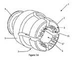
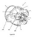
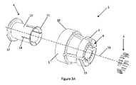
例示的な管状組織変形器(TTT)1を図1A、図2Aおよび図3Aに示す。この装置1は、リーフ2を有し、リーフ2の各々にリテーナ3が設けられている。この実施例では、TTT1はさらにブッシュ4を含む。図1Aにおいて、装置1は、リーフ2が休止位置にあり、ブッシュ4が非前進位置にある第1の形態にある。図2Aは、リーフ2が拡張形態にあり、ブッシュ4が前進位置にある第2の形態にある同じ装置1を示す。 An exemplary tubular tissue deformer (TTT) 1 is shown in FIGS. 1A, 2A and 3A. The
この実施例におけるリーフ2の各々は、付着された管状組織構造を保持する多数のリテーナを有する。各リーフ2上に2つ以上のリテーナを有することは、従来、各リテーナへ組織構造を個々に付着させる必要がある装置において不利であると考えられる場合がある。しかしながら、本発明のTTT1の各リーフ上のリテーナは、各リテーナへの個々の付着を必要とせずに、1ステップで組織構造に同時に付着して保持するように設計されている。このことは、組織構造をリテーナに付着させるのに必要な時間、スキルおよび専門知識を低減し得る。 Each of the
リテーナは、吸引口、ピン、グリッパ、または組織構造に付着させることができる他の要素であり得る。図1Aの実施例では、リテーナはピン3である。ピン3は直線状であり得る、または外向きに湾曲し得る。外向きとは、TTT1を通る長手方向軸19から傾斜することを意味し、長手方向軸19はリーフ2の延在方向と概ね整列している。リテーナは、いくつかの直線状ピンといくつかの湾曲ピンとの組み合わせであってもよい。いくつかの用途では、直線状ピンは、組織構造内に押し込むことがより容易であり得る。いくつかの用途では、湾曲ピンは、組織構造をより良好に保持し、組織構造がTTT1から外れる可能性を低減し得る。直線状ピンは、長手方向軸19から傾斜して延在し得る。異なる角度の直線状ピンの組み合わせがあり得る。 A retainer can be a suction port, pin, gripper, or other element that can be attached to a tissue structure. In the embodiment of FIG. 1A, the retainer is
ピン3の長さは、この実施例では0.2mm~1.5mm、例えば0.5mm~1.2mmである。異なる長さのピン3は、異なる組織構造のような異なる用途に好適であり得る。例えば、短いピンは、小さいまたは薄壁の構造への付着により好適であり、長いピンは、大きいまたは厚壁の構造への付着により好適であり得る。TTT1は、各リーフ2上に様々な長さのピンを有してもよい。各リーフ上に様々な長さのピンを有することにより、付着前の管状組織構造の外層(または外膜)の下準備が低減され得る。このことはまた、結合処置に必要な時間を短縮し得る。 The length of the
多数のリテーナは、組織構造が組織構造の周囲の多数の点で付着するのを可能にし得、このことが各々の付着点にかかる応力を低減し得る。多数の付着点はまた、個々のリテーナへの接続の必要とされる強度を低減し得、このことは、組織構造に大きな穴を作り、潜在的に組織構造の有意な損傷を引き起こし得る大きなピンのような比較的破壊的なリテーナの必要性を回避し得る。さらに、多数の付着点は、押し付けられる組織構造に同時に付着することが可能であり得る、比較的小さい、近接したリテーナ群が使用されることを可能にし得る。組織構造の性質およびサイズ、リテーナのサイズおよびタイプ、ならびにリーフ2の数に応じて、異なる数のリテーナが好適であり得る。例えば、厚壁または比較的非可撓性の組織構造は、大きな組織構造と同様に、1つのリーフ2ごとにより多くのリテーナを必要とし得る。同様に、個々のリテーナがより小さい場合には、より多数のリテーナが必要とされ得る。TTT1が少数のリーフ2を有する場合には、各リーフ2上により多数のリテーナが必要とされ得る。一実施例では、各リーフ2上に2個~10個のリテーナが存在する。一実施例では、TTT1上に合計で少なくとも8個のリテーナが存在する。図1Aの実施例では、各リーフ2上にピン3の形態の8個のリテーナが存在する。この実施例では、TTT1上に合計32個のリテーナが存在する。 Multiple retainers may allow the tissue structure to attach at multiple points around the perimeter of the tissue structure, which may reduce the stress on each attachment point. A large number of attachment points can also reduce the required strength of the connection to an individual retainer, which creates large holes in the tissue structure and potentially large pins that can cause significant damage to the tissue structure. can avoid the need for relatively destructive retainers such as Additionally, multiple attachment points may allow relatively small, closely spaced groups of retainers to be used, which may be able to simultaneously attach to the tissue structure to be pressed against. Different numbers of retainers may be suitable, depending on the nature and size of the tissue structure, the size and type of retainers, and the number of
リテーナは、各リーフ2上に1つまたは複数の列で配置され得る。このことにより、より多くのリテーナを各リーフ2の保持面6に取り付けることができる。図1Aの実施例では、各リーフ2上に、外側列に5本のピン、内側列に3本のピンの2列のピン3が存在する。より多くのリテーナを各リーフ上に取り付けるために、リテーナは、例えば隣接するリテーナ間が0.2mm~0.5mmとなるように、互いに近接して配置され得る。 The retainers may be arranged in one or more rows on each
異なる数のリーフが、異なる用途に好適であり得る。リーフの数が多いほど、特に、組織構造が受け得る任意の拡張または外翻時に、組織構造にかかる力をより均一に分散させることが可能になり得る。リーフの数が少ないほど、操作者が操作するのが容易になり得る。リーフの数は、少なくとも4個または少なくとも5個であり得る。図1Aの実施例では、TTT1は4個のリーフ2を有する。別の実施例では、複数のリーフ2の代わりに単一のリーフが存在し得る。この実施例では、リーフは、可変外周を有する略円筒状または円錐台状であり得る。このようなリーフの外周は、変形、伸張、または巻回および巻戻しによって変化し得る。 Different numbers of leaves may be suitable for different applications. A greater number of leaves may allow for a more even distribution of forces on the tissue structure, especially during any expansion or eversion to which the tissue structure may be subjected. Fewer leaves may be easier for an operator to manipulate. The number of leaves can be at least four or at least five. In the example of FIG. 1A, TTT1 has four leaves2. In another embodiment, instead of
リーフ2は、TTT1を通る通路17の周りに位置決めされ得る。使用時には、組織構造が通路17内に位置決めされ、通路17の開口部の周りにおいてリーフ2上で保持され得る。通路17は、組織構造を収容することができるように寸法決めされる。
リーフ2は、広狭動作するように可撓性である。リーフ2の一部は、長手方向軸19から離れて外向きに、または長手方向軸19に向かって内向きに移動することができる。図1A、図2Aおよび図3Aの実施例では、リーフ2はリングまたは基部5から延びている。リーフ2およびリング5は、一体となって1つの一体型本体10を形成する。リーフ2の遠位端は、通路17の開口部を拡張または収縮するために、軸19に向かっておよび軸19から離れるように移動することができる。このことにより、開口部の直径を変化させて、TTT1または別の組織構造への組織構造の付着を補助することが可能になり得る。リーフ2の外向きの撓みはまた、図6および図7を参照しながらより詳細に説明するように、組織構造を外翻させるのに有用であり得る。 The
リーフ2を内側に撓ませるために、操作者は、例えば鉗子を用いて、リーフ2を把持し、リーフ2を締め付けることができる。このことにより、開口部の直径を小さくして、組織構造の付着をより容易にすることができる。このプロセスを支援するために、リーフ2には、把持しやすくする特徴部が設けられ得る。図1Aの例では、TTT1は、リーフ2に形成された溝7を有し、この溝7は、鉗子の端部を受容し、鉗子がTTT1から外れるのを防止するのに役立ち得る。 In order to flex the
図1Aに示されるものとは異なる構造を有する代替の実施例では、リーフ2の異なる部分が拡張され得る、または狭められ得る。例えば、リーフ2の端部間の一部で組織構造が保持される場合、この部分でリーフ2が拡張され得る、または狭められ得る。 In alternative embodiments having different structures than that shown in FIG. 1A, different portions of
リーフ2は、リーフ2が解放された後に元の形態に戻るように、使用時に経験される典型的な撓み範囲全体にわたって弾性的に可撓性であり得る。
図3Aの分解図において、本体10、リテーナ(ピンの形態)3、およびブッシュ4が別々に示されている。リーフ2の穴8は、この実施例のピン3を受け入れるために設けられる。ピン3は、リーフ2と同様に円の周りに配置される。ブッシュ4は、この図に、より詳細に示されている。 In the exploded view of FIG. 3A, the
ブッシュ4は、実質的に円筒状の本体13を含む。ブッシュ4の前部(すなわち、リーフ2の遠位端に最も近い端部)において、ブッシュ4は支持面11に成形される。この支持面11は、使用時に組織構造の外表面を支持するために設けられる。支持面11は、ブッシュ4の拡径部分から形成され得る。拡径部分はさらに、ブッシュ4が第1の後方位置から第2の前進位置まで前進するにつれて、リーフ2を外方に押し出すためにリーフ2の内表面に当接し得る。拡径部分はまた、リーフ2と係合して、ブッシュ4が前進位置から後方位置に向かって戻るのを阻止し得る。例えば、拡径部分は、拡径部分の後面がリーフ2の端部と接触し、そのことによりリーフ2を通り越して引き戻されるのを阻止するように、リーフ2の端部を越えて延在し得る。代替として、リーフ2の内表面に溝または非対称傾斜部が存在し得、これに拡径部分が係合して、溝からまたは傾斜部の急勾配側を通り越して引き戻されるのを阻止する。
支持面11は、ブッシュ4の本体13から外向きに、かつ本体13に対して鋭角、例えば90°で延在するフランジから形成され得る。代替として、支持面11は、本体13から外向きに湾曲する「フレア状」部分から形成され得る。管状組織構造は、管状組織構造の支持部分の中心から外向きに湾曲する支持面による外向きの湾曲を有するこの表面上で支持され得る。支持面11は、10°~120°、または30°~90°、外向きに湾曲し得る。支持面11は、支持される組織構造の特性に基づいて選択された曲率半径で外向きに湾曲し得る。いくつかの組織構造は、きつく外側にめくられ過ぎると容認できないほどの損傷を受ける場合がある。そのような場合、組織構造の許容できない損傷を引き起こす可能性がある値よりも大きい曲率半径を選択することが有利であり得る。例えば、動脈は、静脈のような他の組織構造と比較して比較的厚いかつ非弾性の壁を有し、きつく外側にめくられ過ぎると容認できないほどの損傷を受ける場合がある。いくつかの実施例では、曲率半径は0.2mmより大きい。 The
ブッシュ4はさらに、第2の前進位置を越えて前進するのを防止するために、フランジ12または他の特徴部を含み得る。フランジ12は、ブッシュ4が前進位置を越えて前方に移動するのを防止するために、リング5の後面または本体10の別の部分に当接し得る。代替として、ブッシュ4は、TTT1の本体10の開口部との摩擦嵌めを形成するための拡径部分、TTT1の本体10の相補的な取付具に嵌合するためのバヨネット式取付具、またはTTT1の本体10に接着するための接着剤を含み得る。ブッシュ4が拡径部分、バヨネット式取付具または接着剤を含む場合、これは、支持面11を形成する拡径部分に加えて、またはその代わりに、ブッシュ4が第2の位置から第1の位置に向かって移動することを阻止するようにさらに作用し得る。
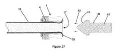
ブッシュ4はさらに、図17および図18を参照ながら詳述するように、ブッシュ4の拡径を可能にするように、本体13内に間隙14を有し得る。間隙14があるにもかかわらず、ブッシュ4は断面が実質的に円形であり得る。実質的に円形とは、ブッシュ4が、完全な円の50%超、75%超、85%超、または好ましくは90%超を形成することを意味するが、言及されている円は、実際の実装において完全な円形でなくてもよいことに留意されたい。 The
ブッシュ4はさらに、リーフ2の撓みを引き起こし得る。この実施例では、ブッシュ4は、通路17内に設けられ、通路17に沿って移動するように構成される。図1Aおよび図2Aに示すように、ブッシュ4は、第1の後方位置(図1A)と第2の前進位置(図2A)との間で移動され得る。ブッシュ4が後方位置にある状態では、リーフ2は拡張されず、すなわち、リーフ2は、図1Aに示すような「休止」形態にある。ブッシュ4が前進位置に移動すると、支持面11を形成する拡径部分の外縁がリーフ2の内表面に当接し、リーフ2を図2Aの半径方向拡張形態へと押し込み、リーフ2をその形態で保持する。代替として、ブッシュ4は、支持面11を形成する拡径部分とは別の部分を有し、リーフ2に当接してリーフ2を拡張させ、および/またはリーフ2を拡張形態で保持し得る。
ブッシュ4は、少なくとも部分的に塑性変形可能であり得る。このことにより、ブッシュ4は力を加えると変形し、力が除去された後も変形した形状を保持することができる。ブッシュ4またはその一部は、用途に応じて適切な変形特性を有する材料から形成され得る。例えば、材料は、(図17および図18を参照しながら詳述する)拡径手順において操作者によって加えられる典型的な力で塑性変形を受けるが、拡径手順の前後にリーフ2および組織構造の保持部分によって加えられる典型的な力でその形状を保持することができる(すなわち、剛性である)ように選択され得る。1つの好適な材料は、金属(例えば、ステンレスまたは外科手術用鋼材、チタン合金、またはコバルト・クロム)であるだろう。別の好適な材料は、ポリテトラフルオロエチレン/シリコーン複合材のようなポリマーであるだろう。
TTT1の一部は、操作者が使用中に組織構造を見ることができるように透明であり得る。特に、ブッシュ4および/またはリーフ2のうちの1つまたは複数は、透明であり得る。 Portions of TTT1 may be transparent so that the operator can see the tissue structure during use. In particular, one or more of
一実施例では、TTT1に吸引口が設けられ得る。吸引口は、単独で、またはピン3と組み合わせてリテーナを構成し得る。一実施例では、吸引口はピン3の端部に設けられる。 In one embodiment, the TTT1 may be provided with a suction port. The suction port may constitute the retainer alone or in combination with the
図4は、リテーナが端部に吸引口29を有するピン3である一実施例を示す。吸引口29は、吸引ライン9を介して低圧源に接続される。図4の実施例では、吸引ライン9は、それぞれのピン3およびリーフ2を貫通し、リング5の領域で低圧源に結合する。この実施例における低圧源は、シリンジ28であり、シリンジ28は、そのプランジャが退避されたときに吸引ライン9内に部分真空を生成する。代替として、低圧源は、真空ポンプまたは同様のものであり得る。 FIG. 4 shows an embodiment in which the retainer is a
図5~図7は、様々な状態の管状組織構造16と共に使用されるTTT1を示す。 5-7
図5において、組織構造16は通路内に位置決めされる。この実施例における組織構造は切断されており、切断端付近の一部18は通路17から延出して、リテーナ(この実施例ではピン3である)の領域内へ延在する。この状態では、ブッシュ4は前進せず、リーフ2は休止位置にある。 In FIG. 5,
図6において、組織構造16は一部18においてリテーナ3に付着されている。図6に見られるように、その部分18は、概ね円形に配置された多くの点でリテーナに付着し、装置1上で保持される。この状態では、ブッシュ4は前進せず、リーフ2は休止位置にある。この位置では、組織構造16のその部分18は完全には外翻していない。リーフ2の動きの範囲、およびリーフ2が後退形態で組織構造16に付着する角度に応じて、組織構造16のその部分18は、部分的に外翻する場合がある、または全く外翻しない場合がある。 In FIG. 6,
図7では、ブッシュ4は前進位置まで前進している。リーフ2は、外向きに拡張されている。このことにより、組織構造16のその部分18は、図5および図6の形態よりも大きく外翻している。組織構造16のその部分18は、最大90°、約90°、または90°を超えて外側にめくられてもよく、完全に「裏返し」にされる必要はない。一実施例では、組織構造16のその部分18は、約90°外側にめくられる。90°の外翻は、いくつかの状況において、必要以上に組織構造16を外側にめくらずに、別の管状組織構造に結合するために管状組織構造16の内表面の大きな領域を示すのに最適であり得る。 In FIG. 7 the
図7には示されていないが、ブッシュ4の支持面はリーフ2の端部近くに位置決めされる。この位置では、ブッシュ4の支持面は、組織構造16の外翻部分18の外表面と接触して、吻合を形成するために別の組織構造と並置するのに好適な広い実質的に円形の表面を形成するように外翻部分18の外表面を支持する。リーフ2の端部はまた、この状態で組織構造の外翻部分のための支持面を形成し得る。この実施例では、リーフ2の支持面6は、ブッシュ4の支持面11の近くに、支持面11に対して小さな角度で位置決めされることにより、リーフ2およびブッシュ4が協働して複合支持面を形成する。リーフ2の支持面6は、この形態において、ブッシュ4の支持面に対して45°未満、30°未満、または15°未満の角度であり得る。代替の実施例では、リーフ2は、ブッシュ4の寄与なしに支持面全体を形成し得る。 Although not shown in FIG. 7, the bearing surface of
図3Aに示されているように、ブッシュ4の支持面11は、ほんの小さな間隙14と共に、実質的に円全体を覆う。拡張された場合であっても、これらの間隙は、隣接するリーフ2間の間隔15よりも小さく、リーフ2の支持面6単体で支持するよりもさらに大きな支持面を形成することができる。このようにして、ブッシュの支持面11は、外翻部分18の実質的に全周にわたって大きな均一に支持された表面を確保するのに役立つ。実質的に全周とは、全周の50%超、75%超、85%超、または好ましくは90%超を意味する。このことは、吻合を形成するために結合されるときに、2つの組織構造間に良好なシールを形成するのに役立ち得る。外翻部分の中心から離れるブッシュ4の支持面11の外向きの湾曲により、組織構造16の外翻部分18は、同様に外向きに湾曲するように支持される。外翻部分18は、その外表面と接触する支持面11によってこの形状で支持される。既に述べたように、このことは、組織構造16の損傷を回避するのに役立ち得る。 As shown in FIG. 3A, the bearing
図8Aは、第1のTTT1、第2のTTT1’、第1の結合装置21および第2の結合装置22を含む、管状組織構造を結合するためのシステム20を示す。図9Aは、システムの分解図であり、第1の結合装置、第2の結合装置、第1のTTT1および第2のTTT1’を別々に示した図である。図9Bは、代替システムの分解図である。図10は、第1の結合装置21および第1のTTT1をより詳細に示した図である。 FIG. 8A shows a
第1のTTT1および第2のTTT1’は、図1A、図2A、図3Aおよび図4~図7を参照しながら説明したTTTであり得る、または異なるTTTであり得る。TTT1、TTT1’は各々、組織構造の周りの少なくとも1つのそれぞれの保持位置27で管状組織構造の一部を保持する。一実施例では、TTT1、TTT1’の各々は、2つ以上の保持位置27で組織構造を保持する。図8の実施例では、TTT1’、TTT1aはそれぞれ4個のリーフ2を有し、各リーフ2は、多数のピン3、3’によって覆われる領域に対応する保持位置27を有する。 The first TTT1 and the second TTT1' can be the TTTs described with reference to FIGS. 1A, 2A, 3A and 4-7, or can be different TTTs. TTT1, TTT1' each hold a portion of the tubular tissue structure at at least one respective holding
第1の結合装置21および第2の結合装置22は、突き合わされて、組織構造の外翻部分を並置して結合し、組織構造を結合することができる。結合装置21、22は、結合されたときに保持装置の保持位置27、27’が確実に互いにオフセットされるようにする。このことは、一方のTTTの保持位置と他方の装置の保持位置との間の間隙を「埋める」ことによって、結合界面の周囲の良好で均一なシールを確保するのに役立ち得る。このことはまた、一方の装置のリテーナが他の装置のリテーナとぶつかる可能性を防止または低減し得る。例えば、リテーナがピンである場合、所定のオフセットは、TTTのピンが互いに接触するのを防止する。ピンが接触した場合、組織構造の保持部分が良好なシールを形成するほど十分につなぎ合わされるのを妨げる可能性がある。 The
結合装置21、22は、それらが長手方向軸25を中心とした相対配向の離散セットのうちの1つにおいてのみ確実に結合するための位置合わせ特徴部を含む。一実施例では、位置合わせ特徴部は、1つまたは複数のピンおよびピンを受容するための1つまたは複数の穴である。ピンは、結合装置の両方または一方のみに設けられ得る。これに対応して、結合装置の両方または一方のみに穴が設けられ得る。図8A、図9Aおよび図9Bの実施例では、第1の結合装置21は2つのピン23を有し、第2の結合装置22は2つの穴24を有する。この実施例におけるピン23は、長手方向軸25を中心として等間隔に離間されるのではない、すなわち、ピン間の回転オフセットは360°/nではなく、この場合、nはピン数である。このことにより、結合装置21、22は、長手方向軸25を中心とした1つの相対配向でしか結合することができないように制限される。ピン23は、穴24の周囲で第2の結合装置22と係合するための歯または返しなどの特徴部を有し得る。ピン23または穴24に接着剤が設けられ得る。ピン23または穴24は、摩擦嵌めを形成するようにテーパ状であり得る。一実施例では、穴24は、一定の断面を有するピン23と係合するようにテーパ状にされる。
各結合装置はさらに、長手方向軸25を中心とした相対配向の離散セットのうちの1つにおいて確実にそれぞれのTTT1を保持することができるように、1つまたは複数の位置合わせ特徴部を有する。すなわち、TTTは、どんな角度でも結合装置内で保持することができるのではなく、そのリテーナが他のTTTのリテーナから確実にオフセットされる角度でしか保持することができない。このことにより、結合装置およびそれぞれのTTT1は、軸25を中心とする1つまたは複数の所定の適合する配向で嵌合することができる。各結合装置は、それぞれのTTT1、TTT1’を受容する凹部26、26’を有し得る。一実施例では、凹部26、26’の内表面は非円形であり得、それぞれのTTT1、TTT1’の一部の外表面も非円形であり得る。装置の非円形は、TTT1、TTT1’が凹部26、26’内に受容されたときに、装置が特定の相対配向からずれて回転するのを防止し得る。図9Bの実施例では、凹部26、26’およびTTT1、TTT1’は多角形である。追加的にまたは代替的に、結合装置21、22に対する特定の相対配向からずれるTTT1、TTT1’の回転を防止する他の嵌合構造が設けられ得る。例えば、これらは、一方の装置のピンと、他方の装置のピンを受容するための穴と、一方の装置の隆起部と、他方の装置の隆起部を受容するための溝とを含み得る。そのような嵌合構造が設けられる場合、凹部26、26’およびTTT1、TTT1’の外側部分は円形であり得る。図8および図9Aの実施例では、凹部26、26’は断面が概ね円形であるが、この実施例ではそれぞれが完全な円を形成していない。より具体的には、各凹部は、断面がほぼ3/4円形である。 Each coupling device further has one or more alignment features to ensure that it can hold its respective TTT1 in one of a discrete set of relative orientations about the
図8Aおよび図9Aの実施例では、結合装置21、22は、断面が概ね円形であるが、完全な円を形成していない。この実施例では、結合装置21、22は、ほぼ3/4円形である。つまり、結合装置21、22はそれぞれ片側が開いているということである。このことにより、結合装置21、22をその側部から管状組織構造の上に移動させて、結合装置21、22の中央開口部内に組織構造を位置決めすることができる。このことは、完全な円形の開口部を通して長手方向に組織構造の切断端を挿入するよりも迅速かつ容易であり得る。開口部はまた、操作者がTTT1、TTT1’および組織構造間の界面を、組織構造を結合しながら見ることを可能にし得る。 8A and 9A,
図10は、第1のTTT1が凹部内に位置決めされた第1の結合装置21を示す。第1のTTT1は、保持部分18の周りの4つの保持位置27で保持された管状組織構造16を有する。 FIG. 10 shows the
図11は、第1の管状組織構造16と第2の管状組織構造16’とを互いに結合するために使用されるシステムを示す。第1のTTT1の保持位置27は、第2のTTT1’の保持位置27’からオフセットされた状態で示されている。第1の結合装置21のピン23は、第2の結合装置22の穴24に挿入された状態で示されている。この形態において、システム20は、2つの管状組織構造16、16’間の結合または吻合を形成する。 FIG. 11 shows a system used to bond together a first
代替の実施例を、図1B、図2B、図3B、図8B、および図9Cに示す。この場合、TTT装置1は5個のリーフ2を有する。図3Bに示されているように、各リーフ2は、フックインサート102を受容する凹部100を有する。各フックインサート102は、図1Aのピン3と同様に管状構造が付着され得る多数のリテーナ/フック3を有する。この実施形態は、装置の製造および組み立てをより容易にし、血管保持のプロセスを改善し得る。フックインサート102は、ワイヤEDM加工を使用して機械加工された鋭利なフック3を有するステンレス鋼のような硬質材料から作製され得る。鋭利で硬質のフック3は、動脈の壁を容易にかつ非外傷的に穿刺する。フックインサート102の基部106は、ブッシュがTTTを通って前進してリーフを半径方向外向きに撓ませるときにブッシュが接触する滑らかな表面を形成する。しかしながら、フックインサート102が挿入されるリーフ2は、ブッシュ4が前進して血管を外翻させるときにリーフ2が半径方向外向きに撓むことができるように、変形可能な状態を維持しなければならない。これを全て実現するために、フックインサート102は、凹部100内に逆行性に挿入され得る別個の構成要素として最も容易に製造される。すなわち、これらの凹部100は、図3Aのピン3を受け入れる穴8と同様に機能し得る。 Alternative embodiments are shown in FIGS. 1B, 2B, 3B, 8B and 9C. In this case the
フック3は、1つのフックインサートにつき3つのフックを含み得る。1つの内側フックと、2つの外側フックとが存在し得る。各フックは、テーパ状であり得、および/または外向きに湾曲し得る。各フックの長さは、0.5mm~2.0mmであり得る。各フックの厚さは、0.05mm~1.00mmであり得、例えば、0.15mmであり得る。
フックインサート102は、締まり嵌めタイプの機構を使用することによって定位置に保持され得る。代替として、フックインサート102の後端にリップを設けて、凹部100内の適所にスナップ嵌めすることができる。別の代替の実施例では、低粘度接着剤を使用して、フックインサート102と凹部100との間を結合することができる。上記のすべての組み合わせを利用することもできる。
フックインサート102は、鉗子がリーフから外れるのを防止するために外表面上にリップ104を有する。鉗子は、保持するために使用され得る血管の上にTTT1を適切に位置決めするために使用される。動脈のような柔らかい管状組織構造がTTTのフック3に付着されているときには、ユーザは、細い鉗子を使用して血管を持ち上げて、血管をフック3に付着させることができる。このプロセス中の血管保持を助け、血管歪みを最小限に抑えるために、ユーザは、鉗子を用いて圧縮力を加えることによって、リーフ2を半径方向内向きに撓ませてフック3を血管壁に近づけることができる。圧縮力が加えられると、リップ104は、鉗子が意図せずに前縁から外れて軟組織構造を損傷するのを防止する。このリップは、図1Aの溝7と同じ機能を果たす。リップの高さは、約0.2mm~1.0mmであり得る。 The
5個のリーフが存在するこの特定の構成では、操作者がTTTの側部からリーフを把持する場合、一方の鉗子先端は上部の1つのリーフに当てられ、他方の鉗子先端は下部の2つのリーフに当てられる。上部のリーフは、最も内側への撓むリーフであり、操作者は動脈をそのフック群に最初に付着させる。操作者は、TTTを回転させて、各リーフ上のリテーナに動脈を付着させながら各リーフを順次圧縮する。 In this particular configuration with five leaves, when the operator grasps the leaves from the side of the TTT, one forceps tip is applied to the top one leaf and the other forceps tip is applied to the bottom two leaves. applied to the reef. The upper leaf is the most inwardly flexing leaf and the operator attaches the artery to its hooks first. The operator rotates the TTT to sequentially compress each leaf while attaching the artery to the retainer on each leaf.
フックインサート102の基部106は、そのそれぞれのリーフ2よりもわずかに半径方向内向きに延在し、したがって、ブッシュ4と接触するのはこの基部106である。この表面は、ブッシュ4がリーフを半径方向に拡張するように前進するにつれて、より滑らかな界面を形成する。上述したように、フックインサートは、ステンレス鋼、チタンまたは硬質プラスチックのような剛性材料であり得る。この文脈における剛性とは、ブッシュ4を最終位置まで押し込むことによって生じる力に応答して生じる性質を指す。 The
リーフ2は、変形可能なプラスチックから成形され得る。各リーフ構造のプラスチックおよび剛性は、ブッシュ4が前進するにつれて、リーフ角度(長手方向軸19に対して)が2°~15°、または約9°変化するように設計され得る。この文脈における変形可能とは、ブッシュ4を最終位置まで押し込むことによって生じる力に応答して生じる性質を指す。
図9Cに示すように、結合装置21のこの実施形態は、TTT1の両側の結合フランジまたはウィング108を受容する凹部26と、TTT1が凹部26から滑り出るのを防止する結合装置21の前部クリップ112上のリップ110とを特徴とする。TTT1およびTTT1’は、外翻した血管の各端部に付着し、各結合装置21、21’に挟み込まれる。次に、2つの結合装置21、21’を近接させ、(それぞれのリーフおよびフックが対向するリーフ間の空間にインターロックするように)回転オフセットされ、次にピン23によって永久的に結合される。代替として、各TTTは結合穴24、24’を含み得、結合ピン23はそれぞれのTTT1、TTT1’に直接係合し得る。 As shown in FIG. 9C, this embodiment of
結合装置21のこの型は、TTT1が適合しなければならない凹部26の視認性を改善し得る。結合ウィング108は、TTT1を上から挿入することを可能にし(または逆に、結合装置21を下から導入することができる)、そのことにより、TTT1をその対応する結合装置21と嵌合させるのに必要な全移動量を低減する。嵌合は、締まり嵌め、または変形可能な前部クリップ112によるスナップロックを使用して実現され得る。 This type of
前部クリップ112は、結合ウィング108を定位置に固定し、順方向の移動を防止する。つまり、TTT1が結合装置から滑り出ない、または中心軸25から傾斜しないということである。 A
このアプローチはまた、結合器全体の長さ(すなわち、結合装置がピン23によって連結される場合)を低減することができる。これは、TTTが最初に通過しなければならない中心間隙が、図9Aに示されているように凹部26に適合するために逆行並進する前に不要となるためである。 This approach can also reduce the length of the overall coupler (ie, where the couplers are connected by pins 23). This is because the center gap through which the TTT must first pass is no longer needed before it can be retrogradely translated to fit into the
次に、図12~図21を参照しながら様々な方法について説明する。これらの方法は、別々の手順として個々に実施され得るか、または1つの手順の一部としてまとめて実施され得る。 Various methods are now described with reference to FIGS. These methods can be performed individually as separate procedures or together as part of one procedure.
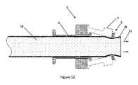
図12において、管状組織構造16の一部18は、矢印33で示される方向にTTT1の通路内へ挿入されている。この実施例では、挿入部分18は組織構造16の切断端である。この実施例におけるTTT1は、図1~図8を参照ながら説明したTTTである。このような実施例では、組織構造16の一部18は、ブッシュ4を通ってリーフ2間に通される。 In FIG. 12, a
図13において、付着用具30は、位置30’において組織構造16の一部18と接触している。付着用具30は、管状組織構造16の開口部に挿入される先端31のような部分を含み得る。付着用具30は、組織構造16の一部18を多数のリテーナに同時に押し付けることができる変形可能な表面32を有する。組織構造16の一部18をリテーナに押し付ける前または押し付けている間に、操作者は、リーフ2を内向きに締め付けてまたは他の方法で収縮させて、リーフ2の端部を互いに接近させ得る。このことにより、特に狭いまたは比較的非可撓性の組織構造の場合に、組織構造をTTT1に付着させるのが容易になる。一実施例では、操作者は、溝7内のTTT1を鉗子で把持し、締め付けてリーフ2を収縮させる。 In FIG. 13,
図14において、用具30は位置30’にあり、変形可能な表面32は、図13に示される状態から変形して、組織構造16の一部18とより良好に接触し、それをリテーナに押し付ける。用具30はさらに、矢印36で示されるように回転されて、組織構造16の一部18の周囲全体の付着を補助し得る。 In FIG. 14,
一部18をリテーナに押し付けることにより、各々の位置がリテーナの1つに対応する多数の位置で、同時にその一部18をリテーナに付着させる。このことにより、組織構造をリテーナに1つずつ付着させる必要がなくなる。矢印37で示されるように、組織構造は、リテーナ上でいくらか外側にめくられて、リテーナに付着される。 Pressing the
用具30は、変形可能な表面32によって封入された空気、水またはゲルなどの流体を含み得る。一実施例では、流体で満たされた領域は、組織構造と接触している領域における用具の拡張を引き起こすために、1つの領域において操作者によって締め付けられ得る、または他の方法で圧縮され得る。このことは、その周囲の全体または大部分で組織構造を穏やかに押圧して、同時に多くのリテーナに迅速に付着させるのを助けることができる。変形可能な表面32は、弾性的に可撓性の表面であり得る。
代替的な実施例では、操作者は、用具30の助けなしに、例えば指で組織構造を押圧することができる。 In an alternative embodiment, the operator can press against the tissue structure without the aid of
図12~図14に示される実施例では、組織構造16の保持部分18は、組織構造の切断端付近の部分である。代替的な実施例では、保持部分は、組織構造の側部におけるスリットの周囲の領域であり得る。このことにより、TTT1を管状組織構造の端側結合のための側部結合器として使用することが可能であり得る。 In the embodiment shown in Figures 12-14, the retaining
図15において、組織構造16は、一部18においてTTT1に付着している。ブッシュ4は第1の後方位置にあり、リーフ2は収縮形態にある。矢印38で示される方向にブッシュ4を押すことによって、操作者は、図16に示される第2の前進位置に向かってブッシュ4を前進させることができる。 In FIG. 15
図16では、ブッシュ4は前進位置にあり、リーフ2の端部は、矢印39で示されるように、半径方向外向きに拡張されている。この拡張は、組織構造16の一部18を外翻させている。外翻部分18は、ブッシュ4の支持面11によって外翻状態で支持されている。ブッシュ4は、外翻部分18の外表面を湾曲支持面11と接触させることによって、外翻部分18を外向きに湾曲した形態に維持する。したがって、TTT1は、ブッシュ4の前進によって組織構造の一部を迅速かつ容易に外翻させることができる。 In FIG. 16
外翻部分の曲率半径は、組織構造を損傷する値よりも大きい値であり得る。曲率半径は、0.2mmより大きい値であり得る。 The radius of curvature of the everting portion can be greater than that which would damage the tissue structure. The radius of curvature can be greater than 0.2 mm.
代替の実施例では、TTT1は、リーフ2を拡張させ、一部18を外翻させるための別の機構を含み得る。例えば、TTT1は、リーフに接続され、後方に摺動してリーフを外向きに引っ張って、その後定位置に固定される外側リングを含み得る。別の代替の実施例では、TTT1は、組織構造を保持するだけでよく、別個の装置を使用して組織構造を外翻させることができる。さらに別の実施例では、以下の図17および図18の拡径プロセスによって、組織構造を外翻させることもできる。 In alternative embodiments,
図17および図18には、管状組織構造の一部を拡径するための用具が示されている。これは、組織構造が、結合される組織構造の直径よりも小さい直径を有する場合に有用であり得る。図17に示されるように、組織構造16の一部18は、TTT1の開口部17の周りに保持される。最初は、この部分は第1の直径を有する。拡径用具40は、開口部17を拡径するために使用され、このことはまた、第2の直径を有するように組織構造16の保持部分18を拡径する。図17および図18の実施例では、拡径用具40のテーパ状部分41は、矢印43で示される方向に開口部17へと挿入される。用具40は、グリップ42で操作者によって把持され得る。 Figures 17 and 18 show a tool for expanding a portion of a tubular tissue structure. This may be useful when the tissue structures have diameters smaller than the diameter of the tissue structures to be joined. As shown in FIG. 17, a
テーパ状部分41の挿入は、図18の矢印44で示されるように、ブッシュ4の塑性変形可能な部分を半径方向外向きに押しやる。このことは、TTT1のリーフ2を外側に押しやる。ブッシュ4は、次に、組織構造をその拡径状態に保持するために、リーフおよび組織構造の内向きの力に対してこの形状を保持することができる。組織構造は、それが付着される別の組織構造の幅により近くなるように拡径され得る。このことは、組織構造を結合するのを補助し得る。結合される組織構造の直径が異なる場合、より小さい直径を有する方の組織構造が拡径され得る。組織構造が同様の直径を有する場合には、拡径プロセスの必要はない。 Insertion of tapered
代替として、拡張可能部分を有する異なる拡径用具が、開口部を拡径するために使用され得る。テーパ状部分の代わりに、拡張可能部分を開口部に挿入して拡張させることにより開口部を拡径してもよい。一実施例では、用具は、流体が用具の別の領域で圧縮されたときに拡張することができる変形可能な表面によって封入された流体を含む。上述したように、開口部の拡張を使用して、リーフを外向きに撓ませ、そのことにより組織構造の保持部分18を外側にめくることによって、組織構造の一部を外翻させてもよい。 Alternatively, a different diameter expansion tool having an expandable portion can be used to expand the opening. Instead of a tapered portion, an expandable portion may be inserted into the opening and expanded to widen the opening. In one example, the device includes a fluid enclosed by a deformable surface that can expand when the fluid is compressed in another region of the device. As described above, the expansion of the opening may be used to evert a portion of the tissue structure by flexing the leaves outward thereby outwardly flipping the retaining
図19~図21において、TTT1およびTTT1’は、結合装置21、22と係合され、組織構造16、16’は、吻合を形成するために結合装置を使用して結合される。 19-21, TTT1 and TTT1' are engaged with
図19において、結合装置21、22は、組織構造16、16’の外翻部分がTTT1、TTT1’上で保持されている間に、側部から組織構造16、16’を通過している。次に、結合装置21、22は、矢印45、45’で示される方向にそれぞれのTTT1、TTT1’に向かって移動される。このことは、図20に示されるように、結合装置21、22をTTT1、TTT1’と係合させる。 In FIG. 19,
図20において、TTT1、TTT1’は、それぞれの結合装置21、22と係合される。この実施例では、TTT1、TTT1’は、図8を参照しながら詳述したように、長手方向軸を中心とした所定の相対角度で結合装置21、22内に位置決めされる。次に、結合装置21、22は、TTT1、TTT1’と共に、矢印45、45’で示される方向に互いに向かって移動されて、互いに係合し、そして組織構造16、16’の外翻部分を互いに接触させる。 In FIG. 20, TTT1, TTT1' are engaged with
図21では、結合装置21、22は、ピン23および穴24によって互いに結合されている。組織構造16、16’の外翻部分はまた、縫合糸またはステープルを必要とせずに、結合装置21、22によって互いに対して保持されることによって、界面50において互いに結合されている。 In FIG. 21 the
図8を参照しながら詳述したように、TTT21、TTT22は、TTTのリテーナ間の所定の回転オフセットで突き合わせられる。図3を参照しながら詳述したように、突き合わされた外翻部分は、実質的にそれらの全周囲において支持される。これらの特徴部は、界面50の周囲の良好なシールおよび流体の最小限の漏出を確実にし得る。 As detailed with reference to FIG. 8, TTT21, TTT22 are butted at a predetermined rotational offset between the retainers of the TTT. As detailed with reference to FIG. 3, the abutted everted portions are supported substantially around their entire perimeter. These features can ensure a good seal around
装置21、22および組織構造16、16’を結合した後、操作者は、漏れまたは不十分な結合の他の徴候について、新たに形成された吻合を観察し得る。これらに気付いた場合、操作者は、縫合糸またはステープルを除去せずに、装置21、22を引き離すことによって装置21、22を切り離すことができる。これは、組織構造16、16’からTTT1、TTT1’を取り外さずに、または組織構造16、16’の保持部分を切断せずに、装置21、22が分離された(および再付着などの任意の他の是正処置がなされた)後に再び突き合わされ得るように、非破壊的プロセスであり得る。 After bonding the
説明する装置、システム、および方法は、管状組織変形器への組織構造の迅速、安全、かつ容易な付着、組織構造の外翻、組織構造の拡径、および組織構造の損傷のリスクを低減した組織構造の結合を可能にし得、これらは、動脈の結合に特に好適であり得る。 The described devices, systems, and methods provided rapid, safe, and easy attachment of tissue structures to tubular tissue deformers, eversion of tissue structures, dilatation of tissue structures, and reduced risk of damage to tissue structures. It may allow the joining of tissue structures and these may be particularly suitable for joining arteries.
本発明の実施形態の説明によって本発明を例証し、実施形態を詳細に説明してきたが、添付の特許請求の範囲をそのような詳細に制限すること、またはいかなる形でも限定することは、本出願人の意図することではない。追加の利点および修正形態は、当業者には容易に明らかになるであろう。したがって、本発明は、そのより広範な局面において、特定の詳細、代表的な装置および方法、ならびに図示および説明した例示的な実施例に限定されない。したがって、本出願人の一般的発明概念の精神または範囲から逸脱することなく、そのような詳細から逸脱してよい。 While the invention has been illustrated by the description of embodiments of the invention and the embodiments have been described in detail, it is not intended to limit the scope of the appended claims to such detail or in any way to limit the scope of the invention. This is not the applicant's intention. Additional advantages and modifications will readily appear to those skilled in the art. Therefore, the invention in its broader aspects is not limited to the specific details, representative apparatus and method, and illustrative examples shown and described. Accordingly, departures may be made from such details without departing from the spirit or scope of applicants' general inventive concept.
Claims (65)
Translated fromJapanese複数のリーフと、
前記複数のリーフの各々の上または前記複数のリーフの各々に隣接する複数のリテーナであって、各々が前記管状組織構造をそれぞれの前記リーフ上でしっかりと保持するように構成された複数のリテーナと
を備える管状組織変形器(TTT)。A tubular tissue deformer (TTT) for tubular tissue structures, comprising:
a plurality of leaves;
a plurality of retainers on or adjacent each of the plurality of leaves, each retainer configured to securely retain the tubular tissue structure on the respective leaf. A tubular tissue deformer (TTT) comprising: and .
前記管状組織構造の一部を押圧して前記管状組織構造を複数の位置で同時に保持するステップを含む方法。A method of attaching a tubular tissue structure to a tubular tissue deformer (TTT), comprising:
A method comprising pressing a portion of the tubular tissue structure to simultaneously hold the tubular tissue structure in multiple locations.
前記管状組織構造の外翻部分を保持するように構成された複数のリーフと、
第1の位置と第2の位置との間で移動可能であるように構成され、前記第2の位置にあるときに前記管状組織構造の前記外翻部分の外表面を支持するように構成されたブッシュと
を備える管状組織変形器(TTT)。A tubular tissue deformer (TTT) for tubular tissue structures, comprising:
a plurality of leaves configured to hold everted portions of the tubular tissue structure;
configured to be movable between a first position and a second position and configured to support an outer surface of the everted portion of the tubular tissue structure when in the second position; A tubular tissue deformer (TTT) comprising a bushing and a .
前記管状組織構造の外翻部分の外表面を、前記外翻部分の中心から離れるように外向きに湾曲する表面の上で支持するステップと
を含む方法。everting a portion of the tubular tissue structure;
supporting an outer surface of the everted portion of the tubular tissue structure on a surface that curves outwardly away from the center of the everted portion.
前記開口部に挿入して前記開口部を拡径し、そのことにより前記管状組織構造の一部を拡径するためのテーパ状部分を備える用具。A tool for expanding a portion of a tubular tissue structure retained on a tubular tissue deformer (TTT) around an opening of the tubular tissue deformer, comprising:
A device comprising a tapered portion for insertion into said opening to expand said opening thereby expanding a portion of said tubular tissue structure.
前記開口部に挿入して、前記開口部内で拡張して前記開口部を拡径し、そのことにより前記管状組織構造の一部を拡径するための拡張可能部分を備える用具。A tool for expanding a portion of a tubular tissue structure retained on a tubular tissue deformer (TTT) around an opening of the tubular tissue deformer, comprising:
A device comprising an expandable portion for insertion into said opening and expanding within said opening to widen said opening, thereby widening a portion of said tubular tissue structure.
前記管状組織構造の前記一部を第1の直径で保持するステップと、
前記管状組織構造の前記一部が保持されている間に、前記管状組織構造の前記一部を前記第1の直径よりも大きい第2の直径に変形させるステップと、
前記第2の直径を有する前記管状組織構造の前記一部を保持するステップと
を含む方法。A method of expanding a portion of a tubular tissue structure, comprising:
holding the portion of the tubular tissue structure at a first diameter;
deforming the portion of the tubular tissue structure to a second diameter greater than the first diameter while the portion of the tubular tissue structure is held;
holding said portion of said tubular tissue structure having said second diameter.
前記管状組織変形器の通路の周囲に位置決めされ、前記管状組織構造の一部を保持するように構成された1つまたは複数のリーフと、
前記通路内に少なくとも部分的に位置決め可能であるように構成されたブッシュと
を備える管状組織変形器であって、
前記ブッシュは、前記1つまたは複数のリーフを半径方向に拡張し、前記リーフを半径方向拡張状態に保持するように少なくとも部分的に塑性変形可能である、管状組織変形器(TTT)。A tubular tissue deformer (TTT) for tubular tissue structures,
one or more leaves positioned around a passageway of the tubular tissue deformer and configured to retain a portion of the tubular tissue structure;
a bushing configured to be at least partially positionable within the passageway, the tubular tissue deformer comprising:
A tubular tissue deformer (TTT) wherein the bushing is at least partially plastically deformable to radially expand the one or more leaves and retain the leaves in a radially expanded state.
管状組織構造の一部を保持するように構成された1つまたは複数のリテーナを有する第1の管状組織変形器(TTT)であって、前記1つまたは複数のリテーナは前記管状組織構造の前記保持部分の周りの1つまたは複数のリテーナ位置に位置決めされる、第1の管状組織変形器(TTT)と、
管状組織構造の一部を保持するように構成された1つまたは複数のリテーナを有する第2の管状組織変形器(TTT)であって、前記1つまたは複数のリテーナは前記管状組織構造の前記保持部分の周りの1つまたは複数のリテーナ位置に位置決めされる、第2の管状組織変形器(TTT)と、
第1の結合装置と、
前記第1の結合装置に結合するように構成された第2の結合装置と
を備えるシステムであって、
前記第1の結合装置および前記第2の結合装置は、前記管状構造の前記保持部分を結合し、前記第1の管状組織変形器の前記1つまたは複数のリテーナ位置と前記第2の管状組織変形器の前記1つまたは複数のリテーナ位置との間の所定の回転オフセットを維持するように構成され、前記回転オフセットは、前記保持部分が結合されるときに前記結合装置を通る長手方向軸を中心とするオフセットである、システム。A system for connecting tubular tissue structures,
A first tubular tissue deformer (TTT) having one or more retainers configured to retain a portion of a tubular tissue structure, said one or more retainers of said tubular tissue structure. a first tubular tissue deformer (TTT) positioned at one or more retainer positions about the retaining portion;
A second tubular tissue deformer (TTT) having one or more retainers configured to retain a portion of a tubular tissue structure, said one or more retainers of said tubular tissue structure. a second tubular tissue deformer (TTT) positioned at one or more retainer positions about the retaining portion;
a first coupling device;
a second coupling device configured to couple to the first coupling device, comprising:
The first coupling device and the second coupling device couple the retaining portion of the tubular structure to the one or more retainer positions of the first tubular tissue deformer and the second tubular tissue. configured to maintain a predetermined rotational offset between the one or more retainer positions of the deformer, the rotational offset aligning a longitudinal axis through the coupling device when the retaining portions are coupled; The system that is the offset to center.
Priority Applications (1)
| Application Number | Priority Date | Filing Date | Title |
|---|---|---|---|
| JP2025083226AJP2025122076A (en) | 2019-11-08 | 2025-05-19 | Tubular Tissue Deformer |
Applications Claiming Priority (3)
| Application Number | Priority Date | Filing Date | Title |
|---|---|---|---|
| NZ758894 | 2019-11-08 | ||
| NZ75889419 | 2019-11-08 | ||
| PCT/NZ2020/050141WO2021091398A1 (en) | 2019-11-08 | 2020-11-04 | A tubular tissue transformer |
Related Child Applications (1)
| Application Number | Title | Priority Date | Filing Date |
|---|---|---|---|
| JP2025083226ADivisionJP2025122076A (en) | 2019-11-08 | 2025-05-19 | Tubular Tissue Deformer |
Publications (2)
| Publication Number | Publication Date |
|---|---|
| JP2023502003Atrue JP2023502003A (en) | 2023-01-20 |
| JPWO2021091398A5 JPWO2021091398A5 (en) | 2023-11-13 |
Family
ID=75848557
Family Applications (2)
| Application Number | Title | Priority Date | Filing Date |
|---|---|---|---|
| JP2022526439APendingJP2023502003A (en) | 2019-11-08 | 2020-11-04 | tubular tissue deformer |
| JP2025083226APendingJP2025122076A (en) | 2019-11-08 | 2025-05-19 | Tubular Tissue Deformer |
Family Applications After (1)
| Application Number | Title | Priority Date | Filing Date |
|---|---|---|---|
| JP2025083226APendingJP2025122076A (en) | 2019-11-08 | 2025-05-19 | Tubular Tissue Deformer |
Country Status (6)
| Country | Link |
|---|---|
| US (1) | US20220378430A1 (en) |
| EP (1) | EP4054437A4 (en) |
| JP (2) | JP2023502003A (en) |
| KR (1) | KR20220112776A (en) |
| CN (1) | CN114929122A (en) |
| WO (1) | WO2021091398A1 (en) |
Cited By (1)
| Publication number | Priority date | Publication date | Assignee | Title |
|---|---|---|---|---|
| JP2024099767A (en)* | 2021-02-26 | 2024-07-25 | 日本電気株式会社 | Control device, control method and control system |
Families Citing this family (2)
| Publication number | Priority date | Publication date | Assignee | Title |
|---|---|---|---|---|
| WO2024102848A1 (en)* | 2022-11-09 | 2024-05-16 | University Of Utah Research Foundation | Vascular anastomosis system |
| CN117064474B (en)* | 2023-10-17 | 2024-01-05 | 山东百多安医疗器械股份有限公司 | Degradable vascular anastomosis device |
Citations (3)
| Publication number | Priority date | Publication date | Assignee | Title |
|---|---|---|---|---|
| JPS5022485A (en)* | 1973-07-04 | 1975-03-10 | ||
| JP2002538925A (en)* | 1999-03-19 | 2002-11-19 | バイ−パス・インク. | Vascular surgery |
| US20130204275A1 (en)* | 2010-04-16 | 2013-08-08 | University Of Utah Research Foundation | Methods, devices and apparatus for performing a vascular anastomosis |
Family Cites Families (12)
| Publication number | Priority date | Publication date | Assignee | Title |
|---|---|---|---|---|
| US5375588A (en)* | 1992-08-17 | 1994-12-27 | Yoon; Inbae | Method and apparatus for use in endoscopic procedures |
| US5881943A (en)* | 1994-06-17 | 1999-03-16 | Heartport, Inc. | Surgical anastomosis apparatus and method thereof |
| US6193734B1 (en)* | 1998-01-23 | 2001-02-27 | Heartport, Inc. | System for performing vascular anastomoses |
| US6890338B1 (en)* | 2001-02-27 | 2005-05-10 | Origin Medsystems, Inc. | Method and apparatus for performing anastomosis using ring having tines with weak sections |
| KR20020091523A (en) | 2001-05-31 | 2002-12-06 | (주)에이치비메디컬스 | Vascular anastomosis device |
| US20040133221A1 (en)* | 2002-09-20 | 2004-07-08 | Sancoff Gregory E. | Connector assembly for joining a graft vessel to a side of a target vessel |
| EP1551315A2 (en)* | 2002-10-04 | 2005-07-13 | St. Jude Medical ATG, Inc. | Self-expanding exterior connectors for creating anastomoses to small-diameter vessels and methods of use |
| SE0401917D0 (en)* | 2004-07-22 | 2004-07-22 | Hakans | Anastomosis device and method |
| KR100876516B1 (en)* | 2007-08-29 | 2008-12-31 | 대구 손 | Absorbent Vascular Anastomosis Device |
| EP2498689A4 (en)* | 2009-11-09 | 2015-04-22 | Cardiovascular Technologies Inc | Tissue closure devices, device and systems for delivery, kits and methods therefor |
| US8945177B2 (en)* | 2011-09-13 | 2015-02-03 | Abbott Cardiovascular Systems Inc. | Gripper pusher mechanism for tissue apposition systems |
| US20140046347A1 (en)* | 2012-08-10 | 2014-02-13 | W. L. Gore & Associates, Inc. | Devices, systems and methods for engaging tissue |
- 2020
- 2020-11-04CNCN202080091775.8Apatent/CN114929122A/enactivePending
- 2020-11-04WOPCT/NZ2020/050141patent/WO2021091398A1/ennot_activeCeased
- 2020-11-04USUS17/755,786patent/US20220378430A1/enactivePending
- 2020-11-04EPEP20883996.9Apatent/EP4054437A4/enactivePending
- 2020-11-04JPJP2022526439Apatent/JP2023502003A/enactivePending
- 2020-11-04KRKR1020227019207Apatent/KR20220112776A/enactivePending
- 2025
- 2025-05-19JPJP2025083226Apatent/JP2025122076A/enactivePending
Patent Citations (3)
| Publication number | Priority date | Publication date | Assignee | Title |
|---|---|---|---|---|
| JPS5022485A (en)* | 1973-07-04 | 1975-03-10 | ||
| JP2002538925A (en)* | 1999-03-19 | 2002-11-19 | バイ−パス・インク. | Vascular surgery |
| US20130204275A1 (en)* | 2010-04-16 | 2013-08-08 | University Of Utah Research Foundation | Methods, devices and apparatus for performing a vascular anastomosis |
Cited By (1)
| Publication number | Priority date | Publication date | Assignee | Title |
|---|---|---|---|---|
| JP2024099767A (en)* | 2021-02-26 | 2024-07-25 | 日本電気株式会社 | Control device, control method and control system |
Also Published As
| Publication number | Publication date |
|---|---|
| WO2021091398A1 (en) | 2021-05-14 |
| KR20220112776A (en) | 2022-08-11 |
| JP2025122076A (en) | 2025-08-20 |
| CN114929122A (en) | 2022-08-19 |
| EP4054437A1 (en) | 2022-09-14 |
| EP4054437A4 (en) | 2023-11-22 |
| US20220378430A1 (en) | 2022-12-01 |
Similar Documents
| Publication | Publication Date | Title |
|---|---|---|
| JP2025122076A (en) | Tubular Tissue Deformer | |
| JP6274233B2 (en) | Clip cartridge system | |
| US6575985B2 (en) | Vessel eversion instrument with conical holder | |
| US7981126B2 (en) | Locking compression plate anastomosis apparatus | |
| US6652542B2 (en) | External anastomosis operators and related systems for anastomosis | |
| US6551334B2 (en) | Externally directed anastomosis systems and externally positioned anastomosis fenestra cutting apparatus | |
| US6726694B2 (en) | Intraluminally directed anvil apparatus and related methods and systems | |
| AU782175B2 (en) | Intraluminally directed anvil apparatus and related methods and systems | |
| EP1987783A2 (en) | Applicator and method for mechanically connecting hollow structures, in particular small blood vessels, as well as auxiliary devices | |
| US20010023354A1 (en) | Locking compression plate apparatus | |
| JP2004534610A (en) | Vascular junction device | |
| US20110130624A1 (en) | System and method for attaching a vessel in a vascular environment | |
| US6712829B2 (en) | Vessel eversion instrument with conical, expandable mandrel | |
| JP2004528120A (en) | Medical implantation method and device | |
| US6736824B2 (en) | Apparatus and method for anastomosis | |
| JP2019506268A (en) | Anastomosis connector | |
| KR102679690B1 (en) | Device for compressing the compressible portion of a catheter pump | |
| US20220160361A1 (en) | Eversion tool and size guide for performing arterial microvascular anastomosis | |
| US7955342B2 (en) | Device for connecting hollow organs, especially blood vessels, by surgery | |
| US20040068217A1 (en) | Self-expanding exterior connectors for creating anastomoses to small-diameter vessels and methods of use | |
| CA2393508A1 (en) | Anastomotic devices and methods |
Legal Events
| Date | Code | Title | Description |
|---|---|---|---|
| A521 | Request for written amendment filed | Free format text:JAPANESE INTERMEDIATE CODE: A523 Effective date:20231102 | |
| A621 | Written request for application examination | Free format text:JAPANESE INTERMEDIATE CODE: A621 Effective date:20231102 | |
| A977 | Report on retrieval | Free format text:JAPANESE INTERMEDIATE CODE: A971007 Effective date:20240624 | |
| A131 | Notification of reasons for refusal | Free format text:JAPANESE INTERMEDIATE CODE: A131 Effective date:20240723 | |
| A521 | Request for written amendment filed | Free format text:JAPANESE INTERMEDIATE CODE: A523 Effective date:20241023 | |
| A02 | Decision of refusal | Free format text:JAPANESE INTERMEDIATE CODE: A02 Effective date:20250121 | |
| A521 | Request for written amendment filed | Free format text:JAPANESE INTERMEDIATE CODE: A523 Effective date:20250519 |