JP2023184036A - Anchor device and anchor device construction method - Google Patents
Anchor device and anchor device construction methodDownload PDFInfo
- Publication number
- JP2023184036A JP2023184036AJP2022097931AJP2022097931AJP2023184036AJP 2023184036 AJP2023184036 AJP 2023184036AJP 2022097931 AJP2022097931 AJP 2022097931AJP 2022097931 AJP2022097931 AJP 2022097931AJP 2023184036 AJP2023184036 AJP 2023184036A
- Authority
- JP
- Japan
- Prior art keywords
- pile
- anchor
- anchor device
- pipe
- hole
- Prior art date
- Legal status (The legal status is an assumption and is not a legal conclusion. Google has not performed a legal analysis and makes no representation as to the accuracy of the status listed.)
- Pending
Links
Images


Landscapes
- Piles And Underground Anchors (AREA)
- Pit Excavations, Shoring, Fill Or Stabilisation Of Slopes (AREA)
- Devices Affording Protection Of Roads Or Walls For Sound Insulation (AREA)
Abstract
Translated fromJapaneseDescription
Translated fromJapanese本発明は、アンカー装置及びアンカー装置の施工方法に関し、特に、上部杭と下部杭を組み合わせたアンカー装置及びその施工方法に関する。 The present invention relates to an anchor device and a method for constructing the anchor device, and particularly to an anchor device that combines an upper pile and a lower pile, and a method for constructing the same.
斜面における落石や地滑り、雪崩などを予防、防護するために、防護柵や防護ネット等の施設を斜面に設置することが行われており、このような施設の斜面への設置には、アンカー(アンカー装置)が用いられている。アンカーは、これらの施設の設置のためだけでなく、アンカーそのものによって斜面の崩落防止機能を備えている場合もある。
このようなアンカーの一つとして、鋼管を用いるパイプアンカーがある。また、パイプアンカーの下部側にアンカーロッドが接続されたハイブリッドタイプのアンカーも用いられている。特許文献1,2には、このようなハイブリッドタイプのアンカーに関する技術が開示されている。In order to prevent and protect against falling rocks, landslides, avalanches, etc. on slopes, facilities such as protective fences and nets are installed on slopes. When installing such facilities on slopes, anchors ( Anchor devices) are used. Anchors are used not only for the installation of these facilities, but also in some cases have the function of preventing slope collapse by the anchor itself.
One such anchor is a pipe anchor that uses a steel pipe. Additionally, a hybrid type anchor is also used in which an anchor rod is connected to the lower side of the pipe anchor.
特許文献1では、岩層に埋設されたアンカーロッドの上部が、下端部が岩層に達するように表土層内に配置されたパイプ体の下部に、球面座金を介して接続され、両者が相対的に回動可能な構成とされていることにより、アンカーロッドに曲げ応力が伝達されないように(引き抜き力に転換)する技術が開示されている。アンカーロッドの曲げ応力が緩和されるとともに剪断破壊等の問題を低減できるという優れた作用効果が得られるものである。一方で、パイプ体とアンカーロッドの一体性が得られるものではなかった。
特許文献2においても、パイプアンカーとアンカーロッドを備えるアンカー装置が開示されており、その中で、アンカーロッドが、パイプアンカーの中を通って、パイプアンカーの上部側でピン止めされるもの等が開示されている。当該アンカーロッドとパイプアンカー上部の接続は、パイプアンカーに対する引抜き力がアンカーロッドへと伝わるようにするための接続という概念、即ち、鉛直方向の荷重が伝わるようにするための接続であり、パイプアンカーとアンカーロッドを一体化するという概念はないものであった。例えば、ピンによる接続において、ピンの軸方向への摺動が生じ得るものであり、パイプアンカーとアンカーロッドが一体化されるものではなかった。In Patent Document 1, the upper part of an anchor rod buried in a rock layer is connected via a spherical washer to the lower part of a pipe body arranged in a topsoil layer so that the lower end reaches the rock layer, and the two are relatively A technique is disclosed in which, by having a rotatable structure, bending stress is not transmitted to the anchor rod (converted into pull-out force). This provides an excellent effect in that the bending stress of the anchor rod is alleviated and problems such as shear failure can be reduced. On the other hand, it was not possible to achieve integrity between the pipe body and the anchor rod.
本発明は、上記の点に鑑み、上部杭と下部杭を有するハイブリッドタイプのアンカー装置において、上部杭と下部杭が一体化されたアンカー装置を提供することを目的とする。 In view of the above points, an object of the present invention is to provide a hybrid type anchor device having an upper pile and a lower pile, in which the upper pile and the lower pile are integrated.
(構成1)
上端部が地表に突出するようにして地中に埋設される上部杭と、安定層に対して定着される下部杭であって、前記上部杭の中を通って前記上部杭の上端から突出する下部杭と、前記上部杭の上端から突出した前記下部杭の上端部を、前記上部杭の長手方向に沿った方向に締め付ける、締め付け部材と、を備える、アンカー装置。(Configuration 1)
An upper pile that is buried in the ground with an upper end protruding from the ground surface, and a lower pile that is fixed to a stable layer, the pile passing through the upper pile and protruding from the upper end of the upper pile. An anchor device comprising: a lower pile; and a tightening member that tightens the upper end of the lower pile protruding from the upper end of the upper pile in a longitudinal direction of the upper pile.
(構成2)
前記締め付け部材が、前記下部杭を挿通させる挿通穴を有し、前記上部杭の上部側に設けられる座金部材と、前記下部杭の上端部に形成されたねじ山と螺合するナットと、によって構成され、前記挿通穴を通された前記下部杭の上端部に前記ナットを螺合して締め付けることで、前記上部杭と前記下部杭が固定的に締結される、構成1に記載のアンカー装置。(Configuration 2)
The tightening member has an insertion hole through which the lower pile is inserted, and includes a washer member provided on the upper side of the upper pile, and a nut screwed into a thread formed at the upper end of the lower pile. The anchor device according to configuration 1, wherein the upper pile and the lower pile are fixedly fastened by screwing and tightening the nut to the upper end of the lower pile passed through the insertion hole. .
(構成3)
前記締め付け部材の外周が、全周的に前記上部杭の外周より外側へ突出しており、その突出量が、前記アンカー装置によって引き留められる索体の直径より大きい、構成1又は2に記載のアンカー装置。(Configuration 3)
The anchor device according to
(構成4)
前記締め付け部材が、前記下部杭の上端部を、前記上部杭の断面視における中心位置に位置決めする、下部杭上部位置決め部材としても機能する、構成1から3の何れかに記載のアンカー装置。(Configuration 4)
The anchor device according to any one of configurations 1 to 3, wherein the tightening member also functions as a lower pile upper positioning member that positions the upper end of the lower pile at a center position in a cross-sectional view of the upper pile.
(構成5)
前記上部杭の中に充填剤が充填される、構成1から4の何れかに記載のアンカー装置。(Configuration 5)
5. The anchor device according to any one of configurations 1 to 4, wherein the upper pile is filled with a filler.
(構成6)
前記上部杭の中に、前記上部杭を補強する補強部材が備えられる、構成1から5の何れかに記載のアンカー装置。(Configuration 6)
The anchor device according to any one of configurations 1 to 5, wherein the upper pile is provided with a reinforcing member for reinforcing the upper pile.
(構成7)
構成2から6の何れかに記載のアンカー装置の施工方法であって、
上部穿孔用のドリルビットで上部孔を掘削するステップと、
前記上部孔に前記上部杭を埋めるステップと、
下部穿孔用のドリルビットで下部孔を掘削するステップと、
前記下部孔に前記下部杭を定着させるステップと、
前記下部杭の上端部を前記挿通穴に挿通し、前記ナットを螺合して締め付けるステップと、を備えるアンカー装置の施工方法。(Configuration 7)
A method for constructing the anchor device according to any one of
drilling an upper hole with a drill bit for upper drilling;
burying the upper pile in the upper hole;
drilling a lower hole with a drill bit for lower drilling;
fixing the lower pile in the lower hole;
A method for constructing an anchor device, comprising the steps of inserting the upper end of the lower pile into the insertion hole, and screwing and tightening the nut.
本発明のアンカー装置(及びその施工方法)によれば、上部杭と下部杭を有するハイブリッドタイプのアンカー装置において、上部杭と下部杭を一体化することが可能となる。 According to the anchor device (and its construction method) of the present invention, in a hybrid type anchor device having an upper pile and a lower pile, it is possible to integrate the upper pile and the lower pile.
以下、本発明の実施形態について、図面を参照しながら具体的に説明する。なお、以下の実施形態は、本発明を具体化する際の一形態であって、本発明をその範囲内に限定するものではない。 Embodiments of the present invention will be specifically described below with reference to the drawings. Note that the following embodiment is one form of embodying the present invention, and does not limit the present invention within its scope.
<実施形態1>
図1(a)は、本発明に係る実施形態1のアンカー装置1の設置状態を示す概略図である。
本実施形態のアンカー装置1は、
上端部が地表に突出するようにして地中に埋設される上部杭であるパイプアンカー11と、
安定層である岩盤層Bに対して定着される下部杭であるアンカーロッド12であって、パイプアンカー11の中を通ってパイプアンカー11の上端から突出するアンカーロッド12と、
パイプアンカー11の上端から突出したアンカーロッド12の上端部を、前記上部杭の長手方向に沿った方向に締め付ける、締め付け部材であり、アンカーロッド12の上端部をパイプアンカー11の断面視における中心位置に位置決めする、下部杭上部位置決め部材でもある座金部材13と、を備える。<Embodiment 1>
FIG. 1(a) is a schematic diagram showing an installed state of the anchor device 1 of Embodiment 1 according to the present invention.
The anchor device 1 of this embodiment is
A
An
It is a tightening member that tightens the upper end of the
パイプアンカー11は、本実施形態では鋼管である。
パイプアンカー11は、主に不安定層である土砂層Aに設置され、土砂層Aの(すべり面Cで生じる)すべり等に対して抵抗する作用を有する。パイプアンカー11の仕様(材質、太さ、厚さに基づく断面性能や、長さ等)に基づくせん断抵抗力や抵抗曲げモーメントに基づいて、例えば図面の左右方向への土砂層Aのすべりに抵抗する機能を有するものである。また、防護柵や防護ネット等の各種の防護施設を斜面に設置する(引き留める)ための索体であるワイヤロープ2よる引っ張り力に対しても、上記と同様に抵抗する作用を有する。
パイプアンカー11は、図1に示されるように、すべり面Cを境とした土砂層Aと岩盤層Bにまたがって埋設されることが好ましいが、土砂層Aにのみ埋設されるものであってもよい。Pipe
The
As shown in FIG. 1, the
アンカーロッド12は、本実施形態では棒鋼材である。
アンカーロッド12は、定着剤15等によって岩盤層Bに対して定着され、パイプアンカー11の中を通ってパイプアンカー11の上端から突出する長さを有して形成される。
アンカーロッド12の上端部には、ナット14と螺合するねじ山が形成されている。
アンカーロッド12は、その下端側が、岩盤層Bに対して定着されていることにより、引き抜き力に対する高い抵抗力を有する。また、その上端側はパイプアンカー11と締結力をもって固定されることで一体化され、これによってパイプアンカー11の上記作用をより高めるように機能する。
The
The upper end of the
The lower end of the
座金部材13は、本実施形態では四角い鋼板である。
座金部材13は、その中心部にアンカーロッド12を挿通させる挿通穴を有しており、パイプアンカー11の上部側に設けられ、挿通穴を通して突出するアンカーロッド12の上端部においてナット14が締結される際の座金となる部材である。なお、本実施形態ではナット14としてダブルナットを用いているが、緩み対策が問題無いのであれば1つのナットであってもよい。
座金部材(締め付け部材)13は、その外周が、全周的にパイプアンカー11の外周より外側へ突出しており、その突出量が、一番小さい所においても、アンカー装置1によって引き留められるワイヤロープ(索体)2の直径より大きい。これにより、ワイヤロープ2がどのような方向で引き留められるかに関わらず、ワイヤロープ2がアンカー装置1から抜けてしまうこと等を低減する効果を得ることができる。The
The
The outer periphery of the washer member (tightening member) 13 protrudes outward from the outer periphery of the
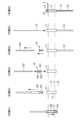
次に、図2を参照しつつ、本実施形態のアンカー装置1の施工の概略について説明する。
先ず、上部穿孔用のドリルビットで上部孔h1を掘削するステップと、当該上部孔h1にパイプアンカー11を埋設するステップを行う。
本実施形態では、特許第4707491号公報や、特許第4834631号公報等によって開示されているボーリングマシン(特に図示せず)と同様の装置を使用して、パイプアンカー11の埋設を行う(当該ボーリングマシンについては、上記公報の他、複数の文献に記載されているものであるため、ここでの説明を簡略化若しくは省略する)。
ドリルビット101及びエアハンマ102等を備えている上記公報に記載のボーリングマシンに、パイプアンカー11を取り付けて掘削することで、上部孔h1の掘削と、パイプアンカー11の埋設が、同時に行われる(手順01)。前述のごとく、本実施形態では、すべり面Cを境とした土砂層Aと岩盤層Bにまたがってパイプアンカー11が埋設される(場合によっては、土砂層Aにのみ形成されるものであってもよい)。
上部孔h1の掘削と、パイプアンカー11の埋設が終わったら、ドリルビット101及びエアハンマ102を抜き去り(手順02)、次に、下部穿孔用のドリルビットで下部孔h2を掘削するステップを行う。なお、上部孔h1が土砂層Aにのみ形成されている場合であっても、下部孔h2は岩盤層Bに必要な定着力を得られる長さをもって形成される。
下部孔h2の掘削は、削岩機(特に図示せず)を用いて行うが、この際に、上部孔h1と下部孔h2の芯だしを行うために、スペーサー(下部穿孔用スペーサー)16を利用する。Next, an outline of construction of the anchor device 1 of this embodiment will be described with reference to FIG. 2.
First, a step of drilling an upper hole h1 with a drill bit for upper drilling and a step of embedding the
In this embodiment, the
By attaching the
When the drilling of the upper hole h1 and the burying of the
The lower hole h2 is excavated using a rock drill (not particularly shown), but at this time, a spacer (lower drilling spacer) 16 is inserted in order to center the upper hole h1 and the lower hole h2. Make use of it.
スペーサー16は、筒状部材161と、筒状部材161の外周に設けられた複数の鍔部162と、上部に設けられたフランジ部163と、を備えている。
筒状部材161は、下部穿孔用のドリルビット(ビット及びロッド)103を挿通可能な筒状の部材である。
鍔部162は、その外径がパイプアンカー11の内径より僅かに小さく形成されており、スペーサー16を、パイプアンカー11の内部でセンタリングさせる機能を有する。
フランジ部163は、その外径が、少なくともパイプアンカー11の内径よりも大きく(好ましくはパイプアンカー11の外径よりも大きく)形成され、従って、スペーサー16をパイプアンカー11の中に挿入した際には、フランジ部163がパイプアンカー11の上端に突き当たり、スペーサー16が保持される。The
The
The
The
埋設されたパイプアンカー11の内部にスペーサー16を設置したら、スペーサー16の筒状部材161の中にドリルビット103を挿通して、削岩機を用いて下部孔h2の掘削を行う(手順03)。前述のごとく、スペーサー16によって、上部孔h1と下部孔h2のセンタリングが行われる。
下部孔h2の掘削が終わったら、ドリルビット103とスペーサー16を抜き去る(手順04)。スペーサー16は、パイプアンカー11の上端に突き当たって保持されているため、容易に取り外すことができる。
下部孔h2が形成されたら、下部孔h2にアンカーロッド12を定着させるステップを行う。
当該ステップでは、下部孔h2に対して定着剤(特に図示せず)を入れた上で、アンカーロッド12を下部孔h2に挿入する(手順05)。アンカーロッド12を挿入した際に、アンカーロッド12を一定数回転させるようにするとよい。定着剤とのなじみを向上したり、定着剤が2液性のものである場合にこれを攪拌することができる。なお、定着剤(若しくは凝固剤)は、設置対象やアンカーロッドの種別等に応じて、必要な定着力が得られる任意の定着剤を用いることができる。定着剤として、グラウト(モルタル)を用いる場合には、「アンカーロッド12を挿入した際に、アンカーロッド12を一定数回転させる」に替えて、アンカーロッド12を上下方向に数回出し入れするようにして、グラウト(モルタル)となじませるようにするとよい。After installing the
When the drilling of the lower hole h2 is completed, the
Once the lower hole h2 is formed, a step of fixing the
In this step, a fixing agent (not particularly shown) is put into the lower hole h2, and then the
最後に、ワイヤロープ2をパイプアンカー11に掛け、アンカーロッド12の上端部を座金部材13の挿通穴に挿通して座金部材13をパイプアンカー11の上部に設置し、ナット14を螺合して締め付けるステップを行う(手順06)。ナット14を締め付けることで、パイプアンカー(上部杭)11とアンカーロッド(下部杭)12が固定的に締結される。なお、ナット14の締め付けは、下部杭が定着した状態で(本実施形態では、定着剤の硬化時間が経過した後に)行う。 Finally, the
以上により、アンカー装置1の打設が行われる。
図1(b)には、実験的に本実施形態のアンカー装置1を、傾斜地に設置した状態の写真を示した。なお、アンカー装置1は、図1(b)に示されるように、傾斜面に対して垂直に打設されるものであってもよいし、鉛直に打設されるものであってもよい。As described above, the anchor device 1 is cast.
FIG. 1(b) shows a photograph of the anchor device 1 of this embodiment experimentally installed on a slope. In addition, as shown in FIG.1(b), the anchor device 1 may be installed perpendicular|vertically with respect to an inclined surface, and may be installed vertically.
以上のごとく、本実施形態のアンカー装置(及びその施工方法)によれば、上部杭と下部杭を有するハイブリッドタイプのアンカー装置において、上部杭(パイプアンカー11)と下部杭(アンカーロッド12)が一体化されることにより、上部杭と下部杭の合成断面が形成され、それぞれが一体化されていない場合に比べ、その断面性能を向上することができる(曲げに対する抵抗力が大きくなっている)。
加えて、上部杭(パイプアンカー11)と下部杭(アンカーロッド12)の水平方向の位置決め(センタリング)が、下部杭上部位置決め部材(座金部材13)によって行われることで、その断面性能に方向性が生じることを低減することができる。これにより、どの方向に荷重がかかっても、同様の機能を発揮することができる。この点は、アンカーロッド12の下端側が岩盤層Bに定着され、その上端側が座金部材13を介してナット14によって締め付けられることによって、アンカーロッド12がパイプアンカー11に固定され、アンカーロッド12とパイプアンカー11が一体化することよって、より効果的となる。
さらに、パイプアンカー11を貫通したアンカーロッド12が、パイプアンカー11の上部の座金部材13にてナット締めされることで、パイプアンカー11が岩盤層Bにしっかりと密着する効果が期待できる。
また、本実施形態のアンカー装置1によれば、アンカーロッド12とパイプアンカー11の締結が、上部に突出した位置で行うことができるため、作業性に優れている。As described above, according to the anchor device (and its construction method) of the present embodiment, in a hybrid type anchor device having an upper pile and a lower pile, the upper pile (pipe anchor 11) and the lower pile (anchor rod 12) By being integrated, a composite cross section of the upper pile and lower pile is formed, and the cross-sectional performance can be improved compared to when each is not integrated (the resistance to bending is greater). .
In addition, horizontal positioning (centering) of the upper pile (pipe anchor 11) and lower pile (anchor rod 12) is performed by the lower pile upper positioning member (washer member 13), which improves the directionality of the cross-sectional performance. This can reduce the occurrence of This allows it to perform the same function no matter which direction the load is applied. In this point, the lower end side of the
Further, the
Further, according to the anchor device 1 of this embodiment, the
<実施形態2>
図3は、実施形態2のアンカー装置1-2の設置状態を示す概略図である。実施形態1と同様の構成については、実施形態1と同一の符号を使用し、ここでの説明を簡略化若しくは省略する。
本実施形態のアンカー装置1-2は、座金部材において、実施形態1のアンカー装置と相違している。
本実施形態の座金部材13´では、底面側に、パイプアンカー11の内部に嵌合する嵌合部材131を備えている。これにより、アンカーロッド12のセンタリングがより確実に行われるものである。
嵌合部材131は、パイプアンカー11に対する座金部材13´の位置決めをすることができるものであればよく、例えば、パイプアンカー11の内径よりわずかに小さい外径を有するリング状の部材や、複数の突起などであってもよい。
なお、ここでは、嵌合部材131がパイプアンカー11の内側に嵌合するものを例としているが、嵌合部材131がパイプアンカー11の外側に嵌合するものであってもよい。<
FIG. 3 is a schematic diagram showing an installed state of the anchor device 1-2 of the second embodiment. For configurations similar to those in Embodiment 1, the same reference numerals as in Embodiment 1 are used, and the description here will be simplified or omitted.
The anchor device 1-2 of this embodiment is different from the anchor device of Embodiment 1 in the washer member.
The washer member 13' of this embodiment includes a
The
In addition, although here, the
本実施形態のアンカー装置1-2によれば、実施形態1と同様の作用効果を得られると共に、アンカーロッド12のセンタリングをより確実に行うことができる。 According to the anchor device 1-2 of this embodiment, the same effects as in the first embodiment can be obtained, and the
<実施形態3>
図4は、実施形態3のアンカー装置1-3の設置状態を示す概略図である。実施形態1と同様の構成については、実施形態1と同一の符号を使用し、ここでの説明を簡略化若しくは省略する。
本実施形態のアンカー装置1-3は、パイプアンカー(上部杭)11の中に充填剤(グラウト)17が充填されている点で、実施形態1のアンカー装置と相違している。
パイプアンカー11にグラウト17が充填されていることにより、上部杭の断面性能をより向上することができるものである。
なお、グラウトとしては、セメント(モルタル)系、ガラス系、樹脂系など、必要な強度が得られる任意のグラウトを用いることができる。<Embodiment 3>
FIG. 4 is a schematic diagram showing an installed state of the anchor device 1-3 of the third embodiment. For configurations similar to those in Embodiment 1, the same reference numerals as in Embodiment 1 are used, and the description here will be simplified or omitted.
The anchor device 1-3 of this embodiment is different from the anchor device of the first embodiment in that a pipe anchor (upper pile) 11 is filled with a filler (grout) 17.
By filling the
Note that as the grout, any grout that can provide the necessary strength can be used, such as cement (mortar) type, glass type, and resin type grout.
本実施形態のアンカー装置1-3によれば、実施形態1と同様の作用効果を得られると共に、上部杭の断面性能をより向上することができる。
なお、下部杭の定着剤と、上部杭の内部に充填する充填剤を、別々のものとしてもよいが、両者を同じものとしても良い。
同じものとする場合には、下部杭の挿入前に、充填剤を上部杭の上部まで充填した後に、下部杭を打設する工程とするとよい。According to the anchor device 1-3 of the present embodiment, the same effects as in the first embodiment can be obtained, and the cross-sectional performance of the upper pile can be further improved.
Note that the fixing agent for the lower pile and the filler filled inside the upper pile may be different, or they may be the same.
If they are the same, it is preferable to fill the filler up to the top of the upper pile with the filler before inserting the lower pile, and then drive the lower pile.
<実施形態4>
図5は、実施形態4のアンカー装置1-4の設置状態を示す概略図である。実施形態1と同様の構成については、実施形態1と同一の符号を使用し、ここでの説明を簡略化若しくは省略する。
本実施形態のアンカー装置1-4は、パイプアンカー(上部杭)11の中に補強部材である内管18が設けられている(2重管となっている)点で、実施形態1のアンカー装置と相違している。2重管とすることで、上部杭の断面性能をより向上することができるものである。
なお、内管18の挿入は、パイプアンカー11の打設後、座金部材13を取り付ける前の間の任意のタイミングで行うことができる。また、先に上部孔h1の掘削をした後で、パイプアンカー11の埋設を行う場合には、予め内管18をパイプアンカー11に取り付けて2重管とした上で、上部孔h1に埋設するもの等であってよい。
本実施形態のアンカー装置1-4によれば、実施形態1と同様の作用効果を得られると共に、上部杭の断面性能をより向上することができる。<Embodiment 4>
FIG. 5 is a schematic diagram showing an installed state of the anchor device 1-4 according to the fourth embodiment. For configurations similar to those in Embodiment 1, the same reference numerals as in Embodiment 1 are used, and the description here will be simplified or omitted.
The anchor device 1-4 of the present embodiment is different from the anchor device of the first embodiment in that an
Note that the
According to the anchor device 1-4 of this embodiment, the same effects as in the first embodiment can be obtained, and the cross-sectional performance of the upper pile can be further improved.
<実施形態5>
図6は、実施形態5のアンカー装置1-5の設置状態を示す概略図である。実施形態1と同様の構成については、実施形態1と同一の符号を使用し、ここでの説明を簡略化若しくは省略する。
本実施形態のアンカー装置1-5は、パイプアンカー(上部杭)11の中に補強部材である内管18が設けられており(2重管となっている)、その内部に充填剤(グラウト)17が充填されている点で、実施形態1のアンカー装置と相違している。2重管とすること及びグラウトが充填されていることにより、上部杭の断面性能がより向上されているものである。<Embodiment 5>
FIG. 6 is a schematic diagram showing an installed state of the anchor device 1-5 of the fifth embodiment. For configurations similar to those in Embodiment 1, the same reference numerals as in Embodiment 1 are used, and the description here will be simplified or omitted.
In the anchor device 1-5 of this embodiment, an
また、本実施形態のアンカー装置1-5は、土圧板19が設けられている点でも実施形態1のアンカー装置と相違している。
土圧板19は、基本的には座金部材13と同様のものであるが、ここでは円形の鋼板で形成されており、座金部材13とスペーサーSを介して配置されている。
土圧板19は、ナット14の締め込みに伴い土壌に対して土圧をかけるように作用し、土砂層Aを安定化する作用が得られるものである。The anchor device 1-5 of the present embodiment also differs from the anchor device of the first embodiment in that an
The
The
本実施形態のアンカー装置1-3によれば、実施形態1と同様の作用効果を得られると共に、上部杭の断面性能をより向上することができる。また、土壌をより安定化させる作用も得られる。
なお、ここではパイプアンカー(上部杭)11の中に設けられる補強部材として、内管18を例としているが、本発明をこれに限るものではなく、補強部材として、例えば鉄筋を用いるもの等であってもよい。上部杭の中に鉄筋を配置して、グラウトを充填することにより、高い断面性能を得ることができる。
また、補強部材は、パイプアンカー(上部杭)の中に設けられるものに限られず、上部杭の外部(例えば、上部杭周囲)に取り付けられるものであってもよい。According to the anchor device 1-3 of the present embodiment, the same effects as in the first embodiment can be obtained, and the cross-sectional performance of the upper pile can be further improved. It also has the effect of further stabilizing the soil.
Although the
Further, the reinforcing member is not limited to being provided inside the pipe anchor (upper pile), but may be attached to the outside of the upper pile (for example, around the upper pile).
なお、各実施形態では、パイプアンカー11が鋼管であるものを例としたが、本発明をこれに限るものではなく、上部杭は、杭工に用いるための必要な強度を有し、内部に下部杭を挿通可能な任意の杭部材を使用することができる。
各実施形態では、アンカーロッド12が棒鋼材であるものを例としたが、本発明をこれに限るものではなく、下部杭は、安定層に定着して必要な引抜き強度を得られる任意の杭部材を使用することができる。
各実施形態では、座金部材13が四角い鋼板であるものを例としたが、本発明をこれに限るものではなく、下部杭上部位置決め部材は、下部杭の上端部を、上部杭の断面視における中心位置に位置決めすることができる任意の部材を使用することができる。
なお、実施形態では、座金部材13がセンタリング機能も有するもの(下部杭上部位置決め部材としても機能するもの)を例としているが、本発明をこれに限るものではなく、「下部杭の上端部を、上部杭の長手方向に沿った方向に締め付ける、締め付け部材」として機能するものであればよく、センタリング機能が無いもの(例えば、アンカーロッドを挿通させる挿通穴が、中心からズレているようなもの)であっても構わない。ただし、センタリング機能を有することでより優れた作用効果が得られる点は、上述の通りである。In each of the embodiments, the
In each embodiment, the
In each of the embodiments, the
In the embodiment, the
実施形態では、上部孔h1の掘削とパイプアンカー11の埋設を、同時に行うものを例としたが、本発明をこれに限るものではなく、先に上部孔h1の掘削を行い、その後に、パイプアンカー11の埋設を行うもの等であって良い。
また、パイプアンカー11の埋設の前に、下部孔h2の掘削も行うものであってもよく、この際の上部孔h1の掘削と、下部孔h2の掘削順番は、前後するものであってもよい。加えて、これらの一方若しくは両方の掘削を行う装置は、エアハンマ―を用いたものであっても良いし、削岩機を用いても良い。
上部孔h1と下部孔h2を先に形成する場合、上部孔h1と下部孔h2が形成された後にパイプアンカー11とアンカーロッド12を打設する順番は、どちらを先にするものであって良い。In the embodiment, the upper hole h1 is excavated and the
Furthermore, before burying the
In the case where the upper hole h1 and the lower hole h2 are formed first, the order in which the
1...アンカー装置
11...パイプアンカー(上部杭)
12...アンカーロッド(下部杭)
13...座金部材(締め付け部材、下部杭上部位置決め部材)
14...ナット
15...定着剤
17...充填剤
18...内管(補強部材)1. .. ..
12. .. .. Anchor rod (lower pile)
13. .. .. Washer member (tightening member, lower pile upper positioning member)
14. .. ..
Claims (7)
Translated fromJapanese安定層に対して定着される下部杭であって、前記上部杭の中を通って前記上部杭の上端から突出する下部杭と、
前記上部杭の上端から突出した前記下部杭の上端部を、前記上部杭の長手方向に沿った方向に締め付ける、締め付け部材と、を備える、アンカー装置。an upper pile buried underground with an upper end protruding above the ground;
a lower pile anchored to the stabilization layer, the lower pile passing through the upper pile and protruding from the upper end of the upper pile;
An anchor device comprising: a tightening member that tightens the upper end portion of the lower pile protruding from the upper end of the upper pile in a direction along the longitudinal direction of the upper pile.
前記下部杭を挿通させる挿通穴を有し、前記上部杭の上部側に設けられる座金部材と、
前記下部杭の上端部に形成されたねじ山と螺合するナットと、によって構成され、
前記挿通穴を通された前記下部杭の上端部に前記ナットを螺合して締め付けることで、前記上部杭と前記下部杭が固定的に締結される、請求項1に記載のアンカー装置。The tightening member is
a washer member provided on the upper side of the upper pile and having an insertion hole through which the lower pile is inserted;
a nut screwed into a thread formed at the upper end of the lower pile;
The anchor device according to claim 1, wherein the upper pile and the lower pile are fixedly fastened by screwing and tightening the nut onto the upper end of the lower pile passed through the insertion hole.
上部穿孔用のドリルビットで上部孔を掘削するステップと、
前記上部孔に前記上部杭を埋めるステップと、
下部穿孔用のドリルビットで下部孔を掘削するステップと、
前記下部孔に前記下部杭を定着させるステップと、
前記下部杭の上端部を前記挿通穴に挿通し、前記ナットを螺合して締め付けるステップと、を備えるアンカー装置の施工方法。A method for constructing an anchor device according to claim 2, comprising:
drilling an upper hole with a drill bit for upper drilling;
burying the upper pile in the upper hole;
drilling a lower hole with a drill bit for lower drilling;
fixing the lower pile in the lower hole;
A method for constructing an anchor device, comprising the steps of inserting the upper end of the lower pile into the insertion hole, and screwing and tightening the nut.
Priority Applications (1)
| Application Number | Priority Date | Filing Date | Title |
|---|---|---|---|
| JP2022097931AJP2023184036A (en) | 2022-06-17 | 2022-06-17 | Anchor device and anchor device construction method |
Applications Claiming Priority (1)
| Application Number | Priority Date | Filing Date | Title |
|---|---|---|---|
| JP2022097931AJP2023184036A (en) | 2022-06-17 | 2022-06-17 | Anchor device and anchor device construction method |
Publications (1)
| Publication Number | Publication Date |
|---|---|
| JP2023184036Atrue JP2023184036A (en) | 2023-12-28 |
Family
ID=89333349
Family Applications (1)
| Application Number | Title | Priority Date | Filing Date |
|---|---|---|---|
| JP2022097931APendingJP2023184036A (en) | 2022-06-17 | 2022-06-17 | Anchor device and anchor device construction method |
Country Status (1)
| Country | Link |
|---|---|
| JP (1) | JP2023184036A (en) |
- 2022
- 2022-06-17JPJP2022097931Apatent/JP2023184036A/enactivePending
Similar Documents
| Publication | Publication Date | Title |
|---|---|---|
| US7338233B2 (en) | Soil nail and method of installing a subsurface support | |
| JP5542529B2 (en) | Hybrid anchor and anchor method | |
| KR100876129B1 (en) | Anchor assembly using PS strand and ground reinforcement method using same | |
| JP4235661B2 (en) | Ground anchor and ground anchor method | |
| KR20130095153A (en) | A removable prestressing steel pipe soil nailing structure | |
| KR101595306B1 (en) | Mechanical fixing earth anchor by rotation and method for constructing this same | |
| KR20140147247A (en) | Foundation slab reinforcement method for integral behavior with existing building and structure of the same | |
| JP2023184036A (en) | Anchor device and anchor device construction method | |
| JP4181192B2 (en) | Ground anchor and ground anchor method | |
| JPS5824017A (en) | Soil stabilization work | |
| KR100776620B1 (en) | Bar Type Anchor | |
| CN113605934B (en) | Reinforced structure for preventing tunnel uphill from slipping down and construction method thereof | |
| CN215857685U (en) | Anchoring cylinder connecting structure | |
| KR20080086254A (en) | Free-standing and non-removable order wall clogging using stranded wire | |
| JP5217216B2 (en) | Anchor head fixing structure, anchor head fixing method, and grout injection method | |
| JP2002047650A (en) | Set anchor body and executing method therefor | |
| JP3813781B2 (en) | Anchor device installation method | |
| KR100690014B1 (en) | Steel structure with spiral plate | |
| KR101158512B1 (en) | Compressing steel bar ground anchor and method for constructing thereof | |
| KR101825018B1 (en) | Combining type load distributive anchor | |
| JP3616321B2 (en) | Ground anchor | |
| JP6179126B2 (en) | Tension material locking structure | |
| JP4172426B2 (en) | Anchor device and installation method | |
| KR200255715Y1 (en) | Anchorage of earth anchor in steel pipe pile for pull-out resistance in the water | |
| JP2003278169A (en) | Ground strength reinforcement structure |
Legal Events
| Date | Code | Title | Description |
|---|---|---|---|
| RD04 | Notification of resignation of power of attorney | Free format text:JAPANESE INTERMEDIATE CODE: A7424 Effective date:20230703 | |
| RD02 | Notification of acceptance of power of attorney | Free format text:JAPANESE INTERMEDIATE CODE: A7422 Effective date:20250110 | |
| RD04 | Notification of resignation of power of attorney | Free format text:JAPANESE INTERMEDIATE CODE: A7424 Effective date:20250110 | |
| A621 | Written request for application examination | Free format text:JAPANESE INTERMEDIATE CODE: A621 Effective date:20250610 |