JP2023180040A - Inspection equipment, its control method, and program - Google Patents
Inspection equipment, its control method, and programDownload PDFInfo
- Publication number
- JP2023180040A JP2023180040AJP2022093097AJP2022093097AJP2023180040AJP 2023180040 AJP2023180040 AJP 2023180040AJP 2022093097 AJP2022093097 AJP 2022093097AJP 2022093097 AJP2022093097 AJP 2022093097AJP 2023180040 AJP2023180040 AJP 2023180040A
- Authority
- JP
- Japan
- Prior art keywords
- image
- inspection
- reference image
- image data
- recording medium
- Prior art date
- Legal status (The legal status is an assumption and is not a legal conclusion. Google has not performed a legal analysis and makes no representation as to the accuracy of the status listed.)
- Pending
Links
Images


Classifications
- H—ELECTRICITY
- H04—ELECTRIC COMMUNICATION TECHNIQUE
- H04N—PICTORIAL COMMUNICATION, e.g. TELEVISION
- H04N1/00—Scanning, transmission or reproduction of documents or the like, e.g. facsimile transmission; Details thereof
- H04N1/46—Colour picture communication systems
- H04N1/56—Processing of colour picture signals
- H04N1/60—Colour correction or control
- H04N1/603—Colour correction or control controlled by characteristics of the picture signal generator or the picture reproducer
- H04N1/6033—Colour correction or control controlled by characteristics of the picture signal generator or the picture reproducer using test pattern analysis
- H04N1/6047—Colour correction or control controlled by characteristics of the picture signal generator or the picture reproducer using test pattern analysis wherein the test pattern is part of an arbitrary user image
- G—PHYSICS
- G06—COMPUTING OR CALCULATING; COUNTING
- G06T—IMAGE DATA PROCESSING OR GENERATION, IN GENERAL
- G06T7/00—Image analysis
- G06T7/0002—Inspection of images, e.g. flaw detection
- G06T7/0004—Industrial image inspection
- G06T7/001—Industrial image inspection using an image reference approach
- G—PHYSICS
- G06—COMPUTING OR CALCULATING; COUNTING
- G06T—IMAGE DATA PROCESSING OR GENERATION, IN GENERAL
- G06T3/00—Geometric image transformations in the plane of the image
- G06T3/40—Scaling of whole images or parts thereof, e.g. expanding or contracting
- G—PHYSICS
- G06—COMPUTING OR CALCULATING; COUNTING
- G06T—IMAGE DATA PROCESSING OR GENERATION, IN GENERAL
- G06T5/00—Image enhancement or restoration
- G06T5/50—Image enhancement or restoration using two or more images, e.g. averaging or subtraction
- G—PHYSICS
- G06—COMPUTING OR CALCULATING; COUNTING
- G06T—IMAGE DATA PROCESSING OR GENERATION, IN GENERAL
- G06T5/00—Image enhancement or restoration
- G06T5/70—Denoising; Smoothing
- G—PHYSICS
- G06—COMPUTING OR CALCULATING; COUNTING
- G06T—IMAGE DATA PROCESSING OR GENERATION, IN GENERAL
- G06T7/00—Image analysis
- G06T7/10—Segmentation; Edge detection
- G06T7/11—Region-based segmentation
- G—PHYSICS
- G06—COMPUTING OR CALCULATING; COUNTING
- G06V—IMAGE OR VIDEO RECOGNITION OR UNDERSTANDING
- G06V10/00—Arrangements for image or video recognition or understanding
- G06V10/20—Image preprocessing
- G06V10/24—Aligning, centring, orientation detection or correction of the image
- G—PHYSICS
- G06—COMPUTING OR CALCULATING; COUNTING
- G06V—IMAGE OR VIDEO RECOGNITION OR UNDERSTANDING
- G06V10/00—Arrangements for image or video recognition or understanding
- G06V10/70—Arrangements for image or video recognition or understanding using pattern recognition or machine learning
- G06V10/74—Image or video pattern matching; Proximity measures in feature spaces
- G06V10/75—Organisation of the matching processes, e.g. simultaneous or sequential comparisons of image or video features; Coarse-fine approaches, e.g. multi-scale approaches; using context analysis; Selection of dictionaries
- G06V10/751—Comparing pixel values or logical combinations thereof, or feature values having positional relevance, e.g. template matching
- H—ELECTRICITY
- H04—ELECTRIC COMMUNICATION TECHNIQUE
- H04N—PICTORIAL COMMUNICATION, e.g. TELEVISION
- H04N1/00—Scanning, transmission or reproduction of documents or the like, e.g. facsimile transmission; Details thereof
- H04N1/46—Colour picture communication systems
- H04N1/56—Processing of colour picture signals
- H04N1/60—Colour correction or control
- H04N1/6016—Conversion to subtractive colour signals
- H—ELECTRICITY
- H04—ELECTRIC COMMUNICATION TECHNIQUE
- H04N—PICTORIAL COMMUNICATION, e.g. TELEVISION
- H04N1/00—Scanning, transmission or reproduction of documents or the like, e.g. facsimile transmission; Details thereof
- H04N1/46—Colour picture communication systems
- H04N1/56—Processing of colour picture signals
- H04N1/60—Colour correction or control
- H04N1/603—Colour correction or control controlled by characteristics of the picture signal generator or the picture reproducer
- H04N1/6033—Colour correction or control controlled by characteristics of the picture signal generator or the picture reproducer using test pattern analysis
- H04N1/6036—Colour correction or control controlled by characteristics of the picture signal generator or the picture reproducer using test pattern analysis involving periodic tests or tests during use of the machine
- G—PHYSICS
- G06—COMPUTING OR CALCULATING; COUNTING
- G06T—IMAGE DATA PROCESSING OR GENERATION, IN GENERAL
- G06T2207/00—Indexing scheme for image analysis or image enhancement
- G06T2207/20—Special algorithmic details
- G06T2207/20212—Image combination
- G06T2207/20221—Image fusion; Image merging
- G—PHYSICS
- G06—COMPUTING OR CALCULATING; COUNTING
- G06T—IMAGE DATA PROCESSING OR GENERATION, IN GENERAL
- G06T2207/00—Indexing scheme for image analysis or image enhancement
- G06T2207/30—Subject of image; Context of image processing
- G06T2207/30108—Industrial image inspection
- G06T2207/30144—Printing quality
Landscapes
- Engineering & Computer Science (AREA)
- Theoretical Computer Science (AREA)
- Physics & Mathematics (AREA)
- General Physics & Mathematics (AREA)
- Multimedia (AREA)
- Computer Vision & Pattern Recognition (AREA)
- Signal Processing (AREA)
- Health & Medical Sciences (AREA)
- Quality & Reliability (AREA)
- Artificial Intelligence (AREA)
- Computing Systems (AREA)
- Databases & Information Systems (AREA)
- Evolutionary Computation (AREA)
- General Health & Medical Sciences (AREA)
- Medical Informatics (AREA)
- Software Systems (AREA)
- Image Processing (AREA)
- Investigating Materials By The Use Of Optical Means Adapted For Particular Applications (AREA)
Abstract
Translated fromJapaneseDescription
Translated fromJapanese本発明は、検査装置とその制御方法、並びにプログラムに関する。 The present invention relates to an inspection device, a control method thereof, and a program.
印刷装置で印刷されて出力される印刷物において、インクやトナー等の色材が、意図しない箇所に付着して汚れが発生する場合がある。或いは、画像を形成すべき箇所に必要十分な色材が付着せず、本来よりも色が薄くなってしまう色抜けが発生する場合がある。こうした汚れや色抜けといった、いわゆる、印刷異常は、印刷物の品質を低下させるものである。そこで、印刷物に異常がないかを検査し、印刷物の品質を保証する必要がある。 2. Description of the Related Art In printed matter printed and output by a printing device, coloring materials such as ink and toner may adhere to unintended locations, causing stains. Alternatively, sufficient coloring material may not adhere to the area where an image is to be formed, resulting in color loss where the color becomes lighter than it should be. So-called printing abnormalities such as stains and color loss degrade the quality of printed matter. Therefore, it is necessary to inspect the printed matter for abnormalities and to guarantee the quality of the printed matter.
印刷異常の有無を検査員が目視で検査する目視検査は、多くの時間とコストを必要とするため、近年、目視に頼らずに、自動で検査を行う検査システムが提案されている。具体的には、印刷に用いたデジタル画像(基準画像)と、印刷物をスキャンして得られたスキャン画像データ(以下、スキャン画像)との位置合わせ行って画像の照合及び異常の有無の判定処理を実行して画像品位を判定するものである。 Visual inspection, in which an inspector visually inspects for the presence of printing abnormalities, requires a lot of time and cost, so inspection systems that automatically perform inspection without relying on visual inspection have been proposed in recent years. Specifically, the digital image used for printing (reference image) is aligned with the scan image data obtained by scanning the printed material (hereinafter referred to as the scan image), and the images are compared and the presence or absence of an abnormality is determined. is executed to determine the image quality.
特許文献1には、CMYK色空間で描画されている基準画像をスキャン画像と同じRGB色空間に変換して検査を行う方法が記載されている。この特許文献1に記載の方法によれば、デジタル画像である基準画像とスキャン画像との比較において、スキャナの状態や色変換の精度により生じる誤差を加味することで誤検知の発生を抑止している。
しかしながら、色合わせにより基準画像とスキャン画像とを近づけただけでは、ノイズにより誤検知が発生してしまう。これは、基準画像はデジタルデータであるため均一な画像であるのに対して、スキャン画像は、紙が持つ表面性や透過率のムラ、スキャナのS/Nなどのノイズを多く含む画像データである。従って、基準画像とスキャン画像とをそのまま比較すると、差分が部分的に増大して誤検知が発生してしまう。 However, simply bringing the reference image and scanned image closer together through color matching will result in false detection due to noise. This is because the reference image is a uniform image because it is digital data, whereas the scanned image is image data that contains a lot of noise such as the surface properties of paper, uneven transmittance, and the S/N of the scanner. be. Therefore, if the reference image and the scanned image are directly compared, the difference will partially increase and false detection will occur.
本発明の目的は、上記従来技術の課題の少なくとも一つを解決することにある。 An object of the present invention is to solve at least one of the problems of the prior art described above.
本発明の目的は、基準画像と、検査対象のスキャン画像との照合において誤検知を抑制し、検査精度を向上させる技術を提供することにある。 An object of the present invention is to provide a technique for suppressing false detections and improving inspection accuracy in comparing a reference image and a scanned image of an inspection target.
上記目的を達成するために本発明の一態様に係る検査装置は以下のような構成を備える。即ち、
印刷装置によって記録媒体に形成された画像の検査を行う検査装置であって、
前記記録媒体に前記画像を形成するのに使用した画像データを基準画像として記憶する記憶手段と、
前記記録媒体に形成された検査対象の画像データを取得する取得手段と、
前記基準画像に乱数を付与する付与手段と、
前記付与手段により前記乱数が付与された基準画像と、前記検査対象の画像データとの位置合わせを行う位置合わせ手段と、
前記位置合わせ手段により位置合わせされた基準画像と前記検査対象の画像データとの照合処理を行う照合手段と、を有することを特徴とする。In order to achieve the above object, an inspection device according to one aspect of the present invention has the following configuration. That is,
An inspection device that inspects an image formed on a recording medium by a printing device,
storage means for storing image data used to form the image on the recording medium as a reference image;
acquisition means for acquiring image data of the inspection target formed on the recording medium;
assigning means for assigning a random number to the reference image;
Aligning means for aligning the reference image to which the random number has been assigned by the assigning unit and the image data to be inspected;
The present invention is characterized by comprising a collation unit that performs a collation process between the reference image aligned by the alignment unit and the image data of the inspection target.
本発明によれば、基準画像と、検査対象のスキャン画像との照合において誤検知を抑制し、検査精度を向上できるという効果がある。 Advantageous Effects of Invention According to the present invention, false detections can be suppressed in comparing a reference image with a scanned image of an inspection target, and inspection accuracy can be improved.
本発明のその他の特徴及び利点は、添付図面を参照とした以下の説明により明らかになるであろう。なお、添付図面においては、同じ若しくは同様の構成には、同じ参照番号を付す。 Other features and advantages of the invention will become apparent from the following description with reference to the accompanying drawings. In addition, in the accompanying drawings, the same or similar structures are given the same reference numerals.
添付図面は明細書に含まれ、その一部を構成し、本発明の実施形態を示し、その記述と共に本発明の原理を説明するために用いられる。
以下、添付図面を参照して本発明の実施形態を詳しく説明する。尚、以下の実施形態は特許請求の範囲に係る発明を限定するものでない。実施形態には複数の特徴が記載されているが、これら複数の特徴の全てが発明に必須のものとは限らず、また、複数の特徴は任意に組み合わせられてもよい。さらに、添付図面においては、同一もしくは同様の構成に同一の参照番号を付し、重複した説明は省略する。 Hereinafter, embodiments of the present invention will be described in detail with reference to the accompanying drawings. Note that the following embodiments do not limit the claimed invention. Although a plurality of features are described in the embodiments, not all of these features are essential to the invention, and the plurality of features may be arbitrarily combined. Furthermore, in the accompanying drawings, the same or similar components are designated by the same reference numerals, and redundant description will be omitted.
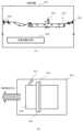
図1は、本発明の実施形態1に係る検査装置を含む検品システムの構成例を示す図である。 FIG. 1 is a diagram showing a configuration example of an inspection system including an inspection device according to
画像形成装置(印刷装置)100は、各種の入力データを処理して、用紙やシート等の記録媒体に印刷を行って印刷物を生成する。検査装置(画像処理装置)200は、画像形成装置100から出力される印刷物を受け取って、その印刷物の内容を検査する。フィニッシャ300は、検査装置200で検査された印刷物を受け取って、例えば製本や綴じ、パンチなどの後処理を行う。画像形成装置100は、ネットワークを介して外部のプリントサーバやクライアントPCと接続されている。また検査装置200は、通信ケーブルを介して画像形成装置100と1対1で接続されている。またフィニッシャ300も上記とは別の通信ケーブルを介して画像形成装置100と1対1で接続されている。更に、検査装置200とフィニッシャ300も別の通信ケーブルを介して相互に接続されている。実施形態1においては、画像の形成、画像の検品、フィニッシングまでを一貫して行うインライン検品システムの例で示している。 An image forming apparatus (printing apparatus) 100 processes various input data and prints on a recording medium such as paper or a sheet to generate printed matter. The inspection device (image processing device) 200 receives a printed matter output from the
図2は、実施形態1に係る画像形成装置100のハードウェア構成を説明するブロック図である。 FIG. 2 is a block diagram illustrating the hardware configuration of the
この画像形成装置100は、コントローラ(制御部)21、プリンタ部206、UI部(操作部)23を有している。尚、UI部23は、操作のための各種スイッチやLED、表示器等を有する。 The
画像形成装置100に送信される画像データや文書データは、ネットワーク上のクライアントPC又はプリントサーバ上の不図示のプリンタドライバ等のソフトウェアアプリケーションで作成される。この画像データや文書データは、PDLデータとしてネットワーク(例えばLocal Area Network)を介して画像形成装置100に送信される。画像形成装置100では、コントローラ21が、送信されたPDLデータを受け取る。 Image data and document data sent to the
コントローラ21は、UI部23とプリンタ部206とに接続され、クライアントPC又はプリントサーバから送信されたPDLデータを受け取り、プリンタ部206で処理可能な印刷データに変換し、その印刷データをプリンタ部206に出力する。プリンタ部206は、コントローラ21より出力された印刷データに基づいて画像の印刷を行う。尚、実施形態1に係るプリンタ部206は、電子写真方式の印刷エンジンを有するものとする。但し、印刷方式はこれに限定されるものではなく、例えばインクジェット方式でもよい。 The
UI部23は、ユーザにより操作され、種々の機能を選択、操作指示を行うために使用される。このUI部23は、表面にタッチパネルが設けられたディスプレイや、スタートキーやストップキー、テンキー等の各種キー等を配置したキーボード等を備えている。 The
次に、コントローラ21の詳細について説明する。 Next, details of the
コントローラ21は、ネットワークI/F(インターフェース)部101、CPU102、RAM103、ROM104、画像処理部105、エンジンI/F部106、内部バス107を有する。ネットワークI/F部101は、ネットワークを介してクライアントPC又はプリントサーバから送信されたPDLデータを受け取る。CPU102は、RAM103やROM104に格納されているプログラムやデータを用いて、この画像形成装置100全体の制御を行うと共に、コントローラ21が行う後述の処理を実行する。RAM103は、CPU102が各種の処理を実行する際に用いるワークエリアを備えている。ROM104には、後述の各種処理をCPU102に実行させるためのプログラムやデータ、また、コントローラ21の設定データなどが格納されている。 The
画像処理部105は、CPU102からの設定に応じて、ネットワークI/F部101が受け取ったPDLデータに対して印刷用の画像処理を行い、プリンタ部206で出力処理可能な印刷データを生成する。画像処理部105は特に、受け取ったPDLデータに対してラスタライズを行うことで、1画素あたり複数の色成分を持つ画像データを生成する。ここで複数の色成分とは、例えばRGB(赤、緑、青)等の色空間において独立した色成分のことである。画像データは、画素毎に1つの色成分につき8ビット(256階調)の値を持つ。即ち、画像データは多値の画素データを含む多値のビットマップデータである。また上記ラスタライズでは、画像データの他に、画像データの画素の属性を画素毎に示す属性データも生成される。この属性データは、画素がどの種類のオブジェクトに属するかを示し、例えば文字や線、グラフィック、イメージ、背景といったオブジェクトの種類を示す値である。画像処理部105は、生成された画像データ及び属性データを用いて、RGB色空間からCMYK(シアン、マゼンタ、イエロー、ブラック)色空間への色変換やスクリーン処理などの画像処理を施すことで印刷データを生成する。エンジンI/F部106は、画像処理部105によって生成された印刷データを、プリンタ部206に出力するインターフェースである。内部バス107は、上述の各部を接続するシステムバスである。 The
図3は、実施形態1に係る画像形成装置100のプリンタ部206の構成を説明する図である。 FIG. 3 is a diagram illustrating the configuration of the
画像形成装置100は、スキャナ部301、レーザ露光部302、感光ドラム303、作像部304、定着部305、給紙/搬送部306、及び、これらを制御するプリンタ制御部308を有している。スキャナ部301は、原稿台に置かれた原稿に対して、照明を当てて原稿上の画像を光学的に読み取り、その画像を電気信号に変換して画像データを作成する。 The
レーザ露光部302は、その画像データに応じて変調されたレーザ光などの光線を等角速度で回転する回転多面鏡(ポリゴンミラー)307に入射させ、その反射光を走査光として感光ドラム303に照射する。作像部304は、感光ドラム303を回転駆動し、帯電器によって帯電させ、レーザ露光部302によって感光ドラム303上に形成された潜像をトナーによって現像する。そのトナー像を用紙に転写し、その際に転写されずに感光ドラム303に残った微小トナーを回収するといった一連の電子写真プロセスの現像ユニット(現像ステーション)を4連持つことで実現している。 The
シアン(C)、マゼンタ(M)、イエロー(Y)、ブラック(K)の順に並べられた4連の現像ユニットは、シアンステーションの作像開始から所定時間経過後に、マゼンタ、イエロー、ブラックの順に、作像動作を実行していく。 The four developing units arranged in the order of cyan (C), magenta (M), yellow (Y), and black (K) develop the colors in the order of magenta, yellow, and black after a predetermined time has elapsed from the start of image formation at the cyan station. , and executes the image forming operation.
定着部305は、ローラやベルトの組み合わせを含み、加熱ローラは、ハロゲンヒータ等の熱源を内蔵し、作像部304によってトナー像が転写された用紙上のトナー像を、熱と圧力によって溶解して用紙に定着させる。尚、厚紙用紙に印刷する場合は、紙が厚く、熱の伝導性が悪いため、定着部305を通過する用紙の搬送速度を、例えば通常の半分の速度にする必要がある。これに起因して、厚紙用紙への印刷の際は、定着部305以外の各部の用紙の搬送速度も半分になるため、画像形成装置100の印刷速度自体が半分となる。 The fixing
給紙/搬送部306は、用紙カセットやペーパーデッキに代表される用紙収納庫を一つ以上備えており、プリンタ制御部308の指示に応じて、用紙収納庫に収納された複数の用紙の中から一枚を分離して作像部304へ搬送する。更に作像部304によってトナー像が転写された用紙を定着部305に搬送する。こうして用紙は搬送され、前述の現像ステーションによって、各色のトナー像が転写され、最終的にフルカラートナー像が用紙上に形成される。また用紙の両面に画像を形成する場合は、定着部305を通過した用紙を再度、作像部304へ搬送する搬送経路を通るように制御する。 The paper feed/
プリンタ制御部308は、画像形成装置100全体を制御するコントローラ21と通信して、その指示に応じて制御を実行する。またプリンタ制御部308は、前述のスキャナ、レーザ露光、作像、定着、給紙/搬送の各部の状態を管理しながら、全体が調和を保って円滑に動作できるよう指示を行う。 The
図4(A)は、実施形態1に係る検査装置200の内部構成を説明する概略図である。 FIG. 4(A) is a schematic diagram illustrating the internal configuration of the
画像形成装置100で印刷された排出された用紙(印刷物)は、給紙ローラ401によって検査装置200に引き込まれる。その後、その印刷物は、搬送ベルト402によって搬送されながら、搬送ベルト402の上方にある検品センサ403で読み取られる。この検品センサ403で読み取られた画像データ(スキャン画像(検査画像))を用いて、検査装置制御部405において検品処理を行う。また検査装置制御部405は、検査装置200全体の制御も行っている。そして、この検品処理による検品結果は、後段のフィニッシャ300に送られる。こうして検品が行われた印刷物は、排紙ローラ404により排出される。尚、ここでは図示しないが、検品センサ403は、両面印刷物にも対応できるように搬送ベルト402の下側からも読み取る構造であってもよい。 The ejected paper (printed material) printed by the
図4(B)は、搬送ベルト402を検品センサ403側から見た上面図である。 FIG. 4(B) is a top view of the
ここで、検品センサ403は、図示したように、搬送されてきた印刷物410の全面の画像をライン毎に読み取るラインセンサである。画像読み取り用の照射装置411は、検品センサ403で読み取る際に印刷物を照射する。斜行検知用の照射装置412は、印刷物410が搬送ベルト402上を搬送される際に、その搬送方向に対して斜行しているかどうかを検知するのに使用される。斜行検知用の照射装置412は、搬送される印刷物410に対して斜め方向から照射することで、その印刷物の端部の影の画像を読み取って斜行を検知する。実施形態1では、印刷物の端部の影画像の読み取りは、検品センサ403で行っているが、検品センサ403以外の別の読取センサで行っても良い。 Here, the
図5は、実施形態1に係る検査装置200の検査装置制御部405の機能構成を説明するブロック図である。 FIG. 5 is a block diagram illustrating the functional configuration of the inspection
検査装置制御部405の制御は、全て制御部503によって行われている。制御部503はCPU515を有し、このCPU515はメモリ部504に展開したプログラムを実行して、後述する各種処理を実行する。画像入力部501は、検品センサ403で読み取って得られた検査対象のスキャン画像データ(以下、スキャナ画像或いは検査画像)を受信する。CPU515は、この受信したスキャン画像をメモリ部504に保存する。また通信部502は、画像形成装置100のコントローラ21と通信を行う。この通信は、スキャン画像に対応した、印刷に利用した画像データ(基準画像データ)の受信と、検品制御情報の送受信である。CPU515はまた、受信した基準画像データ(以下、基準画像)と検品制御情報をメモリ部504に保存する。 All control of the inspection
画像形成装置100との間でやり取りされる検品制御情報の1つは、印刷ジョブ情報、印刷部数情報、ページ順情報等のスキャン画像と基準画像との対応を取るための同期情報である。もう1つは、検品結果情報とそれに伴って画像形成装置100の動作を制御する制御情報である。同期情報は、両面印刷や複数部数の印刷のために、スキャン画像と、そのスキャン画像を印刷するのに利用された基準画像を検品制御装置102で受信する順番が異なる場合のため、基準画像とスキャン画像との同期をとるために必要とされる。また同期情報は、1枚の基準画像が複数のスキャン画像と対応している場合があるため、基準画像とスキャン画像との同期をとるために必要とされる。フィニッシャ300との間でやり取りされる検品制御情報は、検品結果情報と、それに伴いフィニッシャ300の動作を制御する制御情報である。 One of the inspection control information exchanged with the
検品処理部513は、制御部503のCPU515によって動作が制御される。制御部503は、前述した画像形成装置100との間でやり取りされる検品制御情報の1つである同期情報に基づいて、対応している検査画像と基準画像のペアを、検品処理部513を利用して、順次、検品処理を実施する。検品処理部513の詳細は後述する。 The operation of the
検品処理が終了すると、その判定結果は制御部503に送られて操作部/表示部505に表示される。この判定の結果、異常があると判定された場合は、操作部/表示部505でユーザにより予め指定された方法で、通信部502を通して、画像形成装置100とフィニッシャ300の制御を切り替える。例えば、画像形成装置100による像形成処理を停止し、フィニッシャ300の排紙トレイをエスケープトレイに切り替える等の処理を行う。 When the inspection process is completed, the determination result is sent to the
次に検品処理部513の構成について説明する。 Next, the configuration of the
斜向検知部506は、スキャン画像の斜行角度を検知するモジュールである。図4(B)を参照して前述したように、スキャン画像は、印刷物の端部に影ができるようにスキャンされている。これは、検査装置200内に引き込まれて搬送ベルト402上を搬送される印刷物に対して、斜行検知用の照射装置412によって照射された際にできる端部の影を検品センサ403でスキャンするためである。この影を用いて印刷物の斜向角度を検出する。こうして検知した斜向角度に基づいて、後述する画像変形部509で補正処理を行う。 The skew detection unit 506 is a module that detects the skew angle of a scanned image. As described above with reference to FIG. 4(B), the scanned image is scanned so that a shadow is formed at the edge of the printed material. This uses an
色変換部507は、スキャン画像と基準画像の間の色変換を行うモジュールである。基準画像は、画像形成装置100の画像処理部105によってCMYK色空間でラスタライズされた画像データであり、スキャン画像は、検品センサ403が読み取って取得したRGB色空間の画像データである。色変換部507は、基準画像をRGB画像へ変換する。例えば図13(C)のようなCMYK_to_RGBのルックアップテーブル(CMYKからRGBへの変換テーブル)を使用して変換してもよい。 The
この場合、格子点上にある画素データは、この変換テーブルを参照してRGBへ色変換するが、格子点上にない画素データは、隣接する格子点から補間してRGBの値を求める。 In this case, pixel data located on a grid point is color-converted to RGB with reference to this conversion table, but pixel data not located on a grid point is interpolated from adjacent grid points to obtain RGB values.
図13(A)は、基準画像の一例を示す図である。 FIG. 13(A) is a diagram showing an example of a reference image.
領域1301は、基準画像における非印刷部(以降、紙白)であり、X軸1次元の画素領域を示す。この領域1301のX座標は0からNとする。領域1301は紙白であるため、網掛け領域1301の全ての画素はCMYK値(0,0,0,0)であり、上述のCMYKからRGBへの変換テーブルを使用して色変換部507で変換するとRGB値は(220,220,220)となる。尚、RGB値は、8ビットで0~255の値となるため、後述する乱数付加においてサチュレーションしないよう、RGB値を(220,220,220)に変換している。また色変換は、後述する乱数付与部511の結果を加味したCMYKからRGBへの変換テーブルとしてもよい。 An
解像度変換部508は、スキャン画像と基準画像の解像度を変換するモジュールである。スキャン画像と基準画像は、検査装置制御部405に入力された時点で解像度が異なっている場合がある。また検品処理部513の各モジュールで利用される解像度と入力解像度が異なっている場合がある。そのような場合には、このモジュールで解像度を変換する。例えば、スキャン画像が主走査600dpi/副走査300dpiであり、基準画像が主走査1200dpi/副走査1200dpiであるとする。そして検品処理部513で必要とされる解像度が主走査、副走査ともに300dpiである場合は、それぞれの画像を縮小変倍して、両方の画像を主走査及び副走査ともに300dpiの画像とする。この変倍の方法は、計算負荷と必要精度を勘案して、公知の方法を利用すればよい。例えば、SINC関数を利用した変倍を行えば、計算負荷は重いが、高精度の変倍結果を得ることができる。また最近傍法を利用した変倍を行えば、計算負荷は軽いが、低精度の変倍結果を得ることになる。 The
画像変形部509は、スキャン画像や基準画像の変形を行うモジュールである。スキャン画像と基準画像の間には、印刷時の紙の伸縮や斜向、スキャン時の斜向等により幾何的な相違が存在する。画像変形部509は、斜向検知部506や後述する位置合わせ部510で得られた情報を基に画像を変形することにより、その幾何的な相違を補正する。例えば、幾何的な相違は、線型変換(回転、拡大縮小、剪断)と平行移動である。この幾何的な相違は、アフィン変換として表現可能であり、アフィン変換パラメータを斜向検知部506や位置合わせ部510から得ることにより補正を行うことが可能となる。尚、斜向検知部506から得られる情報は、回転に関するパラメータ(斜向角度情報)のみである。 The
位置合わせ部510は、スキャン画像と基準画像の間の位置合わせを行うモジュールである。このモジュールへ入力されるスキャン画像と基準画像は同じ解像度の画像であることが前提である。尚、入力解像度が高いほど、位置合わせの精度が向上するが、計算負荷は大きくなる。位置合わせで得られたパラメータを基に画像変形部509で補正を行うことにより、後述する照合部512で利用する検査画像と基準画像を得ることが可能となる。位置合わせ手法としては、様々な位置合わせ手法が考えられるが、実施形態1では、計算負荷を減らすために、画像全面ではなく、画像の一部領域の情報を利用して、画像全面の位置合わせを行う手法を利用する。実施形態1に係る位置合わせは、位置合わせ用パッチの選択、パッチごとの位置合わせ、アフィン変換のパラメータの推定の3つのステップを含む。以下、それぞれのステップについて説明をしていく。 The
まず位置合わせ用パッチの選択について説明する。ここで「パッチ」は、画像内の矩形領域を指すこととする。位置合わせ用パッチの選択では、基準画像から、位置合わせに適した複数個のパッチを選択する。位置合わせに適したパッチとしては、パッチ内のコーナー特徴量が大きいパッチが考えられる。コーナー特徴とは、ある局所近傍で方向の異なる2つの際立ったエッジが存在するような特徴(2つのエッジの交点)である。コーナー特徴量は、このエッジ特徴の強さを表す特徴量である。「エッジ特徴」のモデル化の違いに基づき、様々な手法が提案されている。 First, selection of alignment patches will be explained. Here, a "patch" refers to a rectangular area within an image. In selecting patches for alignment, a plurality of patches suitable for alignment are selected from the reference image. Patches that are suitable for alignment may include patches with large corner feature amounts. A corner feature is a feature in which two distinct edges with different directions exist in a certain local vicinity (an intersection of two edges). The corner feature is a feature representing the strength of this edge feature. Various methods have been proposed based on differences in the modeling of "edge features."
コーナー特徴量を計算する方法の1つとして、例えば、Harrisのコーナー検出法と呼ばれる公知の方法がある。Harrisのコーナー検出法は、水平方向の微分画像(水平方向のエッジ特徴量画像)と、垂直方向の微分画像(垂直方向のエッジ特徴量画像)から、コーナー特徴量画像を計算する。このコーナー特徴量画像は、コーナー特徴を構成する2つのエッジの内、弱い方のエッジ量を表現した画像となっている。コーナー特徴は、2つのエッジのどちらも強いエッジであるはずなので、相対的に弱い方のエッジであっても強いエッジ量を持っているどうかでコーナー特徴量の大きさを表現している。 One of the methods for calculating the corner feature amount is, for example, a known method called the Harris corner detection method. Harris's corner detection method calculates a corner feature image from a horizontal differential image (horizontal edge feature image) and a vertical differential image (vertical edge feature image). This corner feature amount image is an image expressing the weaker edge amount of the two edges that constitute the corner feature. Since the corner feature should have two strong edges, the magnitude of the corner feature amount is expressed by whether or not even the relatively weaker edge has a strong edge amount.
基準画像からコーナー特徴量画像を計算し、大きなコーナー特徴量を持つ部分を位置合わせに適したパッチとして選択する。単純にコーナー特徴量が大きい領域を順番にパッチとして選択すると、偏った領域からのみパッチが選択される場合がある。このような場合には、周辺にパッチが存在しない領域が増え、その領域の画像変形情報を利用できないことになるので、画像全体の位置合わせをするのに適した状態ではない。そこで、パッチを選択する際には、単にコーナー特徴量の大きさではなく、パッチが画像内に分散して配置されることも考慮する。具体的には、あるパッチ候補領域のコーナー特徴量が画像内全体の中での値が大きくなかったとしても、画像の局所的な領域内での値が大きければ、パッチとして選択するようにする。こうすることにより、基準画像内にパッチを分散して配置することが可能となる。パッチ選択の際のパラメータとしては、パッチの大きさ、パッチの個数(又は密度)がある。パッチが大きくなり、パッチの個数が多くなると、位置合わせの精度が向上するが、計算負荷は大きくなる。 A corner feature image is calculated from the reference image, and a portion with a large corner feature is selected as a patch suitable for alignment. If regions with large corner features are simply selected as patches in order, patches may be selected only from biased regions. In such a case, the number of areas around which no patches exist increases, and the image deformation information for that area cannot be used, so the situation is not suitable for aligning the entire image. Therefore, when selecting patches, consideration is given not only to the size of the corner feature amount but also to the fact that the patches are dispersed within the image. Specifically, even if the corner feature value of a certain patch candidate area is not large in the entire image, if the value in a local area of the image is large, it is selected as a patch. . By doing so, it becomes possible to disperse and arrange patches within the reference image. Parameters used in patch selection include patch size and number (or density) of patches. As the patches become larger and the number of patches increases, the accuracy of alignment improves, but the computational load increases.
次にパッチごとの位置合わせについて説明する。パッチごとの位置合わせは、前段で選択した基準画像内の位置合わせ用パッチと、それに対応するスキャン画像内のパッチとの間で位置合わせを行っていく。 Next, position alignment for each patch will be explained. Patch-by-patch alignment is performed between the alignment patch in the reference image selected in the previous stage and the corresponding patch in the scanned image.
位置合わせの結果として、得られる情報は2種類あり、1つ目は、i番目(i=1~N、Nはパッチ数)の基準画像内の位置合わせ用パッチの中心座標(refpX_i,refpY_i)である。2つ目は、その中心座標のスキャン画像内での位置(scanpX_i,scanpY_i)である。位置合わせ手法は、(refpX_i,refpY_i)と(scanpX_i,scanpY_i)の関係が得られるようなシフト量推定方法であれば、どのような手法であってもよい。例えば、FFTを用いて、位置合わせ用パッチと対応するパッチを周波数空間上に持っていき、そこでの相関をとり、シフト量を推定する方法などが考えられる。 There are two types of information obtained as a result of alignment. The first is the center coordinates (refpX_i, refpY_i) of the alignment patch in the i-th (i = 1 to N, N is the number of patches) reference image. It is. The second is the position (scanpX_i, scanpY_i) of the center coordinate within the scan image. The alignment method may be any shift amount estimation method that can obtain the relationship between (refpX_i, refpY_i) and (scanpX_i, scanpY_i). For example, a method can be considered in which FFT is used to bring the patch corresponding to the alignment patch onto the frequency space, and the correlation therebetween is calculated to estimate the shift amount.
最後に、アフィン変換パラメータの推定について説明する。アフィン変換は、図13(B)に示す式で表現される座標変換方法である。 Finally, estimation of affine transformation parameters will be explained. Affine transformation is a coordinate transformation method expressed by the formula shown in FIG. 13(B).
この式で、アフィン変換パラメータは、a,b,c,d,e,fの6種類が存在する。ここで、(x,y)は(refpX_i,refpY_i)に対応し、(x',y')は(scanpX_i,scanpY_i)に対応する。N個のパッチから得られる、この対応関係を用いて、アフィン変換パラメータを推定する。例えば、最小二乗法を用いて、アフィン変換パラメータを求めることが可能である。こうして求められたアフィン変換パラメータに基づいて、画像変形部509で基準画像又はスキャン画像を変形することにより、位置合わせ補正後の画像データを作成する。こうして照合部512での照合に利用する基準画像と検査画像の組を求めることができる。 In this equation, there are six types of affine transformation parameters: a, b, c, d, e, and f. Here, (x, y) corresponds to (refpX_i, refpY_i), and (x', y') corresponds to (scanpX_i, scanpY_i). The affine transformation parameters are estimated using this correspondence obtained from the N patches. For example, it is possible to obtain affine transformation parameters using the least squares method. Based on the affine transformation parameters thus obtained, the
乱数付与部511は、基準画像へ乱数を付与するモジュールである。付与する乱数は、スキャン画像と基準画像の間の画像差を調整するためのものであり、何も異常がなくても、スキャン画像と基準画像とでは差異が存在する。この差異は、画像形成装置の特性の影響、スキャナ特性の影響等により生じる。画像形成装置の特性は、色再現性やドットゲインやガンマ特性などである。スキャナ特性は、色再現性やS/NやスキャナMTFなどである。画像形成装置やスキャナの色再現性については色変換部507において差異を除去している。そのため乱数付与部511では、その他のノイズ部分の差異を除去するため基準画像に乱数を付与する。例として、例えば図7に示すような縦9、横9のサイズで、横方向i番目、縦方向j番目の乱数パターンを、図8に示すような分割された基準画像の領域毎に付与する流れを説明する。 The random
図7は、実施形態1に係る乱数マップの一例を示す図である。図8は、実施形態に係る基準画像を分割した一例を示す図である。 FIG. 7 is a diagram illustrating an example of a random number map according to the first embodiment. FIG. 8 is a diagram illustrating an example of dividing the reference image according to the embodiment.
図8に示すように、縦45画素(以下、pixel=px)、横45pxの基準画像を、乱数パターンと同じサイズの複数の領域に分割する。ここで図8の領域802を例に乱数の付与を説明する。この領域802の画像は左上原点(0,0)の座標系である。この画像に図7(A)の乱数パターン701を適用して乱数を加える。ここで加える乱数は、画素座標位置に対応する乱数パターン701の座標(i,j)の乱数である。例えば座標(1,0)に対応する画素がRGB値(100,101,102)としたとき、これに加算する乱数は、乱数パターン701の座標(i=1,j=0)の乱数となる。図7(A)の例では、座標(1,0)の乱数は「1」であるため、RGB値のそれぞれに「1」を加算する。同様にして、基準画像全体へ乱数を付与することで、分割された基準画像の領域毎に乱数を付与することができる。 As shown in FIG. 8, a reference image of 45 pixels vertically (hereinafter referred to as pixel=px) and 45 pixels horizontally is divided into a plurality of regions having the same size as the random number pattern. Here, assigning random numbers will be explained using the
同様にして、スキャン画像に対しても複数の領域に分割し、全ての分割されたスキャン画像の領域にも同様の処理を行うことで、スキャン画像全体へ乱数を付与することができる。 Similarly, by dividing the scan image into a plurality of regions and performing similar processing on all the divided regions of the scan image, random numbers can be assigned to the entire scan image.
ここで、付加する乱数の大きさは、微小な変化で効果を発揮する。実施形態1では、乱数パターンを0~2の間で変化させたが、内部処理において小数点単位で画素値を計算できる場合は、0~1の小数点単位で変化させてもよい。ここでは、異常として検出されないような大きさ、或いは輝度のノイズを付与する必要がある。 Here, the magnitude of the added random number exhibits its effect even with minute changes. In the first embodiment, the random number pattern is changed between 0 and 2, but if the pixel value can be calculated in decimal units in internal processing, it may be changed in decimal units of 0 to 1. Here, it is necessary to add noise of such a size or brightness that it will not be detected as an abnormality.
尚、実施形態1では、0以上の乱数を加算する例を説明したが、本発明はこれに限らない。例えば、0を中心として正負の値を使用しても良いし、乱数を加算するのではなく減算してもよい。 In the first embodiment, an example in which random numbers of 0 or more are added is described, but the present invention is not limited to this. For example, positive or negative values may be used with 0 as the center, or random numbers may be subtracted instead of added.
尚、乱数パターンは特に限定しないが、後述する近傍探索によるブロックマッチングに使用する窓サイズの中に、ノイズを含むものとノイズを含まない乱数パターンであることが望ましい。図7(A)の乱数マップ701を例にすると、どの注目画素でも窓内にノイズが含まれていない「0」と、ノイズが含まれている「1」又は「2」が含まれている。尚、乱数パターンはこれに限らず、例えばRGB値それぞれで乱数パターンを持っていてもよい。 Although the random number pattern is not particularly limited, it is desirable that the window size used for block matching by neighborhood search, which will be described later, includes a random number pattern that includes noise and a random number pattern that does not include noise. Taking the
ここで、図13(A)の基準画像を例に乱数の付与の一例を説明する。 Here, an example of assigning random numbers will be described using the reference image of FIG. 13(A) as an example.
領域1301のRGB値は、色変換部507で変換した通り(220,220,220)である。この1次元領域を座標(X,0:Xは0~8)で表し、各座標に対応する画素に乱数パターン701を加える。加えた結果を図14(A)のグラフ1401に示す。グラフ1401の縦軸はRGBの各画素値を表し、横軸はX座標を示す。グラフ1401では、図7(A)のパターン701の1行目(j=0)の乱数が加算された例を示している。基準画像では、紙白は常に一定の画素値であったが、乱数を加えることにより変動していることがわかる。 The RGB values of the
再び図5に戻り、照合部512は、検査画像と基準画像とを照合するモジュールである。このモジュールへ入力される検査画像と基準画像は同じ解像度の画像データである。また、画像の比較が可能なように、位置合わせ部510得られた情報を基に、基準画像又は検査画像が画像変形部509で補正されていることが前提である。 Returning to FIG. 5 again, the
照合部512は、乱数付与部511で乱数が付与された基準画像と検査画像とを用いて照合画像を作成する。ここで、照合画像を作成する際、位置合わせ部510で得られた情報から更に高精度に位置を合わせることで、高精度な異常の検出が可能となる。実施形態1では、近傍探索によるブロックマッチングにより高精度な位置合わせを実現する。操作部/表示部505から通知されるパラメータに基づいて照合処理が実施される。照合処理の詳細については後述する。尚、高精度な位置合わせは、ブロックマッチングに限らない。位置合わせ部510で得られた情報から狭い領域で詳細な位置合わせが行われるとよいため、局所領域での特徴点の位置合わせなどでも良い。 The
操作部/表示部505は、タッチスクリーンのユーザインターフェースであって、検品処理部513における処理の設定をユーザから受け付ける。例えば、操作部/表示部505は、例えば、図10に示す設定画面を表示し、検品処理部513による画像処理の設定をユーザから受け付ける。 The operation unit/
図10は、実施形態1に係る検査装置200の操作部/表示部505に表示されるUI画面の一例を示す図である。 FIG. 10 is a diagram showing an example of a UI screen displayed on the operation unit/
ここで、ユーザが調整可能な検査設定として、設定1~設定5がある。例えば、設定1が設定されると、照合部512は、検査画像の検査で判定した汚れ、キズ等の色差が「5」以上の場合に異常と判定する。一方、設定5が設定されると、照合部512は、検査画像の検査で判定した汚れ、キズ等の色差が「50」以上の場合に異常と判定する。図10の例では、検査設定の設定番号が小さいほど、照合部512はわずかな汚れ、キズ等の色差であっても異常と判定する。このようにユーザは、設定1~設定5からいずれかの設定ボタンを選択して「する」ボタンを押下することで、照合部512が異常、即ち異常と判定する閾値を設定することができる。色差の算出については後述する照合判定処理で詳細に説明する。尚、図10の例において、それぞれの設定値には、予め色差パラメータが対応付けされている。従って、ユーザが選択した設定値に対応した色差パラメータが、操作部/表示部505から照合部512へ通知される。 Here, there are
実施形態1では、図10に示すような設定値に基づいて、検出する汚れ、キズの色差を調整したが、これに限定するものではなく、例えば、検出する汚れ、キズの大きさを設定できるようにしてもよい。例えば、0.1mm~3mmの範囲等で大きさを設定できるようにしても良い。 In the first embodiment, the color difference of the dirt and scratches to be detected is adjusted based on the setting values as shown in FIG. 10, but the invention is not limited to this. For example, the size of the dirt and scratches to be detected can be set. You can do it like this. For example, the size may be set in a range of 0.1 mm to 3 mm.
次に、実施形態1に係る検査装置200による検品処理について説明する。 Next, inspection processing by the
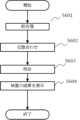
図6は、実施形態1に係る検査装置200による検品処理を説明するフローチャートである。尚、このフローチャートで示す処理は、メモリ部504に保存されているプログラムを制御部503のCPU515が実行することで実現される。このときCPU515は、図5に示す検査処理部513の各処理部として機能し、処理された結果はメモリ部504で保持されて後続の処理で利用される。 FIG. 6 is a flowchart illustrating inspection processing by the
まずS601でCPU515、検品処理の前処理を行う。このときCPU515は、通信部502経由でメモリ部504に保持されている、画像形成装置100から受信した検品制御情報を用いて、処理するべきスキャン画像と基準画像とのペアを選択する。そしてCPU515は、スキャン画像を斜向検知部506で処理し、スキャン画像の傾き情報を得る。そして、その傾き情報にもとづいて、画像変形部509において、スキャン画像の補正処理を行う。これと並行して、前述の基準画像の生成処理を行うことで、基準画像を色変換部507で処理をして検品処理に適した画像とする。 First, in S601, the
次にS602に進みCPU515は、S601で得られたスキャン画像と基準画像を用いて位置合わせを行う。このときCPU515は、スキャン画像と基準画像を解像度変換部508で所定の解像度(例えば、300dpi×300dpi)に変換する。そして、所定の解像度となったスキャン画像と基準画像とを位置合わせ部510で処理して、アフィン変換パラメータを得る。そしてCPU515は、位置合わせ部510から得たアフィン変換パラメータを用いて、画像変形部509で基準画像の補正処理を行い、基準画像の座標系をスキャン画像と同じにして照合に利用可能な画像とする。 Next, the process advances to S602, and the
そしてS603に進みCPU515は、S802で得られた検査画像(スキャン画像)と基準画像を用いて照合/判定処理を行う。このときCPU515は照合部512として機能し、検査画像と基準画像との照合を行う。そしてS604に進みCPU515は、S603の照合処理の結果を操作部/表示部505に表示する。ここでは、単に最終判定結果画像を表示するだけでは、どのような画像障害であったかが把握しづらいので、検査画像に最終判断結果画像を合成して、操作部/表示部505に表示する。この合成は、画像障害の場所が把握しやすい合成方法であれば、どのような合成方法でもよい。例えば、最終判断結果画像において「1」と判断された部分(異常部分)を赤色にし、検査画像に重畳して表示するようにしても良い。 Then, the process advances to S603, and the
次に照合処理について図11に示すフローチャートを用いて説明する。 Next, the matching process will be explained using the flowchart shown in FIG. 11.
図11は、実施形態1に係る検査装置200による照合処理を説明するフローチャートである。このフローチャートで示す処理は、メモリ部504に保存されているプログラムを制御部503のCPU515が実行することで実現される。このときCPU515は、図5に示す照合部512として機能する。 FIG. 11 is a flowchart illustrating the verification process by the
まずS1101で照合部512は、基準画像と検査画像において近傍探索による高精度な位置合わせを行う。ここでは、前述したように画像変形部509にて基準画像と検査画像の位置合わせを行っているが、高精度に異常を検出するために、更に局所的な位置合わせを行う必要がある。そこで実施形態1では、ブロックマッチングを用いた近傍探索による高精度な位置合わせを行う。ここで近傍探索時における模式図を示す。 First, in step S1101, the
図12は、実施形態1に係る近傍探索の模式図である。 FIG. 12 is a schematic diagram of neighborhood search according to the first embodiment.
図12(A)は検査画像、図12(B)は基準画像の一例を示す。基準画像のエリア1201(所定領域)は、基準画像の探索領域を示す。検査画像の探索窓1202は、画素1203の8近傍画素を対象領域としている。そして基準画像のエリア1201内で、この探索窓1202に対応する探索窓1204を設定する。そして、この探索窓1204をエリア1201内で右方向に4画素ずつ移動し(x+4)、この探索窓1204がエリア1201の右端に到達するとx座標を元に戻しy座標を-4して探索窓1204を、最初の探索窓1204の位置に真下に移動する。この動作を繰り返して、このエリア1201で、検査画像の探索窓1202と最も差が小さい基準画像の領域を順次探索する。ここで求める差Δareaは、以下の式(1)に示す色差ΔRGBの対象領域の合計値とする。 FIG. 12(A) shows an example of a test image, and FIG. 12(B) shows an example of a reference image. A reference image area 1201 (predetermined area) indicates a search area of the reference image. The
ΔRGB=√(R2+G2+B2) … 式(1)
ここで、乱数付与部511で乱数を付与した場合と、乱数を付与しなかった場合の差分について述べる。ΔRGB=√(R2 +G2 +B2 )...Equation (1)
Here, the difference between the case where random numbers are assigned by the random
図13(A)の基準画像の領域1301は、色変換部507にて紙白であり、RGB(220,220,220)と説明した。この領域1301に近傍探索によるブロックマッチングを実施すると、紙白領域のみの画素では優劣が付かない。一方で乱数を付与した場合、探索窓領域毎にみると、Δareaの最大値と最小値が変化する。そして近傍探索によるブロックマッチングでは、探索窓領域において最小値となる部分を選択する。そのため基準画像に乱数を付与した場合の方が、より高精度に位置合わせを行うことができる。 The
次にS1102に進み照合部512は、S1101において再度位置合わせを行った基準画像と検査画像の差分画像を算出する。実施形態1では、RGBのGにおける差であるΔGを異常を検出するための色差とし、この色差を算出する例で説明する。尚、実施形態1では、RGB値のGの差であるΔGを色差としたが、ΔRGBを色差として異常を検出してもよい。 Next, the process advances to S1102, and the
また、グレースケール画像であれば単純な差の絶対値でもよいし、ガンマ特性を考慮した差の絶対値を求める関数であってもよい。 Further, in the case of a grayscale image, a simple absolute value of the difference may be used, or a function that calculates the absolute value of the difference in consideration of gamma characteristics may be used.
図14(B)は、検査画像のRGB値の内、Gを表したグラフ1402を示す。このグラフの縦軸はGの画素値を表し、横軸はX座標を示す。尚、ここで述べるX座標は、図13(A)の基準画像と位置が同一の検査画像の1次元領域であり、異常は含まれておらず、ノイズが混入しているものとする。 FIG. 14B shows a
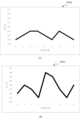
図15は、実施形態1に係る基準画像と検査画像のグラフを示す図である。 FIG. 15 is a diagram showing a graph of the reference image and the inspection image according to the first embodiment.
図15において、実線は図14(B)と同じ検査画像のGを表しており、破線は基準画像を表している。図15において、グラフの縦軸はGの画素値を表し、横軸はX座標を示す。図15(A)は、基準画像にノイズを付与していない場合を示す。図15(B)は、図14(A)に示すように、基準画像に乱数パターン701を加えた結果と図14(B)の検査画像のGを示すグラフ1402とを比較する場合を示す。図15(C)は、照合部512により、近傍探索により位置合わせを行った場合の検査画像と基準画像との比較例を示す。 In FIG. 15, the solid line represents G of the same inspection image as in FIG. 14(B), and the broken line represents the reference image. In FIG. 15, the vertical axis of the graph represents the G pixel value, and the horizontal axis represents the X coordinate. FIG. 15(A) shows a case where no noise is added to the reference image. FIG. 15(B) shows a case where the result of adding the
図15(A)では、X座標位置の4と5においてΔGが5以上離れている。このとき前述の図10に示すように、操作部/表示部505で設定した検査設定が設定1の場合、ΔGが「5」以上離れている場合は異常とみなすため誤検知となる。 In FIG. 15A, ΔG is 5 or more apart at X coordinate
また図15(B)の場合も図15(A)と同様に、X座標位置の4と5において差が5以上離れているため、設定1の場合では誤検知が発生してしまう。 Also in the case of FIG. 15(B), as in FIG. 15(A), the difference between the X coordinate
これに対して図15(C)では、差が最も離れているものでX座標位置の2において「4」であるため、この場合は上述の設定1であっても、異常とは検知されない。 On the other hand, in FIG. 15C, the difference is the farthest and is "4" at the X coordinate
以上説明したように、上記処理と乱数付与部511の処理により、本来であれば検査画像に含まれるノイズにより誤検知が発生する。しかしながら、基準画像にも乱数が付与された状態で、近傍探索による、検査画像と基準画像との局所的な位置合わせを行うことにより、検査画像に含まれるノイズを打ち消した状態で照合判定処理を行うことができ、誤検知を抑制することができる。 As explained above, due to the above processing and the processing of the random
尚、付与する乱数は、操作部/表示部505から通知されるパラメータに基づく検査設定に応じて変化させてもよい。具体的には、検査設定が高く(大きく)なると付加するノ乱数(イズ量)を増やし、検査設定が低く(小さく)なると付加する乱数(ノイズ量)を減らすようなテーブルを設け、検査設定に応じて切り替えてもよい。 Note that the random number to be given may be changed according to test settings based on parameters notified from the operation unit/
図7(B)の乱数パターン702は、検査設定を1つ高くした場合の乱数パターンの一例を示す図である。このように検査設定が大きくなると、同様にら数(ノイズ量)を大きくしたテーブルに切り替える。これは付与する乱数の値を、異常として検知されない大きさや輝度の範囲で変化させることで、誤検知の抑制効果を更に高めることができるためである。 A
(実施形態1の変形例)
以下、本発明の実施形態1の変形例に関わる画像処理を説明する。(Modification of Embodiment 1)
Image processing related to a modification of the first embodiment of the present invention will be described below.
上述の実施形態1では、基準画像を印刷に用いたデジタル画像とし、検査画像と基準画像におけるノイズ成分を打ち消し、照合をより高精度に行う例で説明した。しかしながら、検査システムでは、基準画像をデジタル画像にするだけでなく、検査画像と同様に印刷しスキャンを行い、異常がないとユーザが決定したスキャン画像を基準画像とするものもある。 In the above-described first embodiment, an example has been described in which the reference image is a digital image used for printing, noise components in the inspection image and the reference image are canceled out, and matching is performed with higher precision. However, some inspection systems not only convert the reference image into a digital image, but also print and scan the reference image in the same way as the inspection image, and use the scanned image determined by the user as having no abnormalities as the reference image.
スキャン画像を基準画像とする場合、スキャン画像は紙が持つ表面性や透過率のムラ、スキャナのS/Nなどのノイズが含まれている。そのため乱数を付与する必要がない。そこで、基準画像にスキャンした画像を使用する場合は、乱数付与部511にて乱数を付与しないように切り替える。 When a scanned image is used as a reference image, the scanned image contains noise such as surface properties of paper, uneven transmittance, and S/N of the scanner. Therefore, there is no need to assign random numbers. Therefore, when using a scanned image as a reference image, the random
以上説明したように、この変形例によれば、基準画像を印刷に用いたデジタル画像とした場合でも、基準画像を検査画像と同様に、印刷物をスキャンして得られたスキャン画像とした場合でも、ノイズ成分を打ち消した状態で照合処理判定を行うことができる。よって、検査画像の異常として誤って検知するのを抑制することができる。 As explained above, according to this modification, even when the reference image is a digital image used for printing, and even when the reference image is a scanned image obtained by scanning a printed matter like the inspection image, , it is possible to perform the matching process determination in a state where the noise component is canceled out. Therefore, it is possible to prevent the inspection image from being erroneously detected as abnormal.
[実施形態2]
以下、本発明の実施形態2に係る画像処理を説明する。[Embodiment 2]
Image processing according to
上述の実施形態1では、基準画像に乱数を付与することで検査画像に含まれるノイズ成分を打ち消し、好適に照合判定を行う方法について説明した。 In the above-described first embodiment, a method has been described in which noise components included in the test image are canceled out by adding random numbers to the reference image to suitably perform the matching determination.
実施形態1では乱数を付与する際、注目画素の画素値に依らず、図7の乱数マップに従って乱数を付与した。しかしながら、検査画像に含まれるノイズは、暗部よりも、紙白やハイライト部の方が大きくなる。これは検品センサ403がRGB受光素子であるため、ハイライト部の方が感度が高くなることに起因している。 In the first embodiment, when assigning random numbers, the random numbers are assigned according to the random number map shown in FIG. 7, regardless of the pixel value of the pixel of interest. However, the noise contained in the inspection image is larger in white paper and highlight areas than in dark areas. This is because the
そこで実施形態2では、画素値に応じて付与する乱数の値を変化させる。これにより、暗部や紙白、ハイライト部といった各部分に、より好適な乱数を付与することができ、誤検知抑制につながる。尚、以下では、実施形態1との差分のみについて説明する。実施形態2に係るシステムの構成及び、画像形成装置100、検査装置200のハードウェア構成等は前述の実施形態1と同様であるため、その説明を省略する。 Therefore, in the second embodiment, the value of the random number to be given is changed depending on the pixel value. As a result, more suitable random numbers can be assigned to each portion such as dark areas, white paper, and highlighted areas, leading to suppression of false detection. Note that, below, only the differences from
実施形態2に係る乱数付与部511は、基準画像の画素値を参照し、その画素値に応じた係数を、付与する乱数に乗算することで好適な乱数の付与を実現する。 The random
実施形態1と同様、図8の基準画像の画像領域802を用いて説明する。座標(2,0)がRGB値(0,96,192)としたとき、乱数パターンはi=2,j=0のものを加算する。ここで以下の式(2)に、暗部の係数D、紙白部の係数H、座標(2,0)のRGB値のうちRに乱数パターン(i,j)の乱数値randが付与されたR’の計算例を示す。下記式(2)では、紙白に近いほど付加する乱数は大きくなり、暗部では小さくなる。これにより、紙白やハイライトといったノイズの影響を受けやすい明部の画素には大きな乱数を、暗部のようなノイズの影響を受けにくい画素には小さな乱数を付与することができる。 As in the first embodiment, the description will be made using the
R'=(((H-D)*R)÷255+D)*rand+R …(式2)
上式より、R=0、D=1、H=5としたとき、randは「2」であり、R’は10となる。G,Bも同様に計算することで、基準画像の画素値を参照した好適な乱数の付与が実現できる。R'=(((HD)*R)÷255+D)*rand+R...(Formula 2)
From the above equation, when R=0, D=1, and H=5, rand is "2" and R' is 10. By similarly calculating G and B, suitable random numbers can be assigned with reference to the pixel values of the reference image.
尚、乱数付与において、線形な演算式により乱数を求めたが、本発明はこれに限らない。画素値に対応するルックアップテーブルを参照して、乱数を求めてもよい。 Incidentally, in assigning the random numbers, the random numbers were obtained using a linear arithmetic expression, but the present invention is not limited to this. A random number may be determined by referring to a lookup table corresponding to the pixel value.
以上説明したように実施形態2によれば、基準画像の画素値に応じて付与する乱数の値を変化させことにより、暗部や紙白、ハイライト部といった各部分に、より好適な乱数を付与することができ、誤検知の抑制につながるという効果がある。 As explained above, according to the second embodiment, by changing the value of the random number assigned according to the pixel value of the reference image, more suitable random numbers are assigned to each part such as the dark part, white paper, and highlight part. This has the effect of suppressing false positive detections.
[実施形態3]
以下、本発明の実施形態3に係る処理を説明する。[Embodiment 3]
The processing according to the third embodiment of the present invention will be described below.
前述の実施形態1では、基準画像に乱数を付与することで検査画像に含まれるノイズ成分を打ち消し、好適に照合判定を行う方法について説明した。実施形態1では、乱数を付与する際、事前に設定した乱数を付与していた。しかしながら、印刷出力用紙410や検品センサ403の個体差によってノイズの量や分布は変化する。そこで実施形態3では、印刷出力用紙410や検品センサ403の個体差を考慮した乱数を付与する例で説明する。尚、以下では実施形態1との差分のみについて説明する。実施形態3に係るシステムの構成及び、画像形成装置100、検査装置200のハードウェア構成等は前述の実施形態1と同様であるため、その説明を省略する。 In the above-described first embodiment, a method has been described in which noise components included in the test image are canceled out by adding random numbers to the reference image to suitably perform the matching determination. In the first embodiment, when assigning random numbers, random numbers set in advance are assigned. However, the amount and distribution of noise changes depending on individual differences in the
図16は、実施形態3に係る検査装置の検査装置制御部の機能構成を説明するブロック図である。尚、図16において、前述の図5の構成と同一の部分は同じ参照番号で示し、それらの説明を省略する。 FIG. 16 is a block diagram illustrating the functional configuration of the inspection device control section of the inspection device according to the third embodiment. Incidentally, in FIG. 16, the same parts as in the configuration of FIG. 5 described above are indicated by the same reference numerals, and their explanation will be omitted.
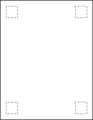
実施形態3に係る検品処理部513は、印刷出力用紙410や検品センサ403の状態を判定するために状態判定部514を有する。この状態判定部514は、印刷出力用紙410に何も印刷せずに印刷処理を実行し、検品センサ403で読み取ることでノイズ量の測定を行う。検品センサ403では、図9に示すような印刷出力用紙410の四隅領域を読み取り、その値を状態判定部514へ送る。 The
図9は、実施形態3における印刷出力用紙410の四隅領域を説明する図である。 FIG. 9 is a diagram illustrating the four corner areas of the
図17は、実施形態3に係る検査装置200による状態判定処理を説明するフローチャートである。このフローチャートで示す処理は、メモリ部504に保存されているプログラムを制御部503のCPU515が実行することで実現される。このときCPU515は、図16に示す状態判定部514として機能する。 FIG. 17 is a flowchart illustrating state determination processing by the
まずS1701で状態判定部514は、検品センサ403で読み取った印刷出力用紙410の各四隅領域におけるノイズ量のRGB値の最大値と最小値を取り除く。次にS1702に進み状態判定部514は、全ての領域でS1701の処理が終わったか判定する。終わっていない場合はS1701を繰り返し実施し、終わった場合はS1703に遷移する。S1703で状態判定部514は、四隅全ての領域についてノイズ量の分散値を算出する。ここではRGB値のうち、Rを例に説明する。分散値S2は、S1701でRの最大値と最小値を取り除いた全画素数をnとし、各画素値xiと、画素値xiの平均値より、以下の式(3)で求められる。First, in step S1701, the
S2=(1/n)Σ{xi-(xiの平均値)}2 …式(3)
ここでΣは、n=1からn=nまでの総和を示す。S2 = (1/n)Σ{xi-(average value of xi)}2 ...Equation (3)
Here, Σ represents the sum from n=1 to n=n.
同様に、G,Bに対しても求めることで、RGB値の全ての分散値を算出することができる。 Similarly, by calculating for G and B, it is possible to calculate all the variance values of the RGB values.
尚、実施形態3では、処理速度を考慮し、検品センサで読み取る領域を四隅としたが、本発明はこれに限定されない。用紙全体で最大値から数%、最小値から数%のRGB値を取り除き、残ったRGB値の分散値を算出するとしても良い。 In the third embodiment, the area to be read by the inspection sensor is set to the four corners in consideration of processing speed, but the present invention is not limited to this. It is also possible to remove several percent of the RGB values from the maximum value and several percent from the minimum value for the entire paper sheet, and then calculate the variance value of the remaining RGB values.
乱数付与部511は、状態判定部514で算出した分散値に基づいて、付与する乱数を変化させる。ここでは分散値を基に使用する乱数マップを切り替えたり、標準偏差と乱数マップを生成させたりしてもよい。例えば閾値を「5」とし、算出された分散値が閾値を超える場合、図7(A)の乱数マップ701から、図7(B)に示すような、付与する乱数が大きくなる乱数マップ702へ切り替えるようにしても良い。 The random
以上説明したように実施形態3によれば、印刷出力用紙410や検品センサ403の個体差を考慮したノイズ量の調整が可能となり、より高い精度で異常検出が可能となる。 As described above, according to the third embodiment, it is possible to adjust the amount of noise in consideration of individual differences in the
尚、実施形態3では印刷出力用紙410や検品センサ403の個体差に基づいて付与する乱数を切り替える例で述べたが、本発明はこれに限らない。画像形成装置100のスキャナやプリンタの特性や状態を加味してCMYK階調を読み取って乱数を変更するようにしてもよい。 In the third embodiment, an example has been described in which the random numbers to be provided are changed based on individual differences between the
(その他の実施形態)
本発明は、上述の実施形態の1以上の機能を実現するプログラムを、ネットワーク又は記憶媒体を介してシステム又は装置に供給し、そのシステム又は装置のコンピュータにおける1つ以上のプロセッサがプログラムを読出し実行する処理でも実現可能である。また、1以上の機能を実現する回路(例えば、ASIC)によっても実現可能である。(Other embodiments)
The present invention provides a system or device with a program that implements one or more functions of the embodiments described above via a network or a storage medium, and one or more processors in a computer of the system or device reads and executes the program. This can also be achieved by processing. It can also be realized by a circuit (for example, ASIC) that realizes one or more functions.
[項目1]
印刷装置によって記録媒体に形成された画像の検査を行う検査装置であって、
前記記録媒体に前記画像を形成するのに使用した画像データを基準画像として記憶する記憶手段と、
前記記録媒体に形成された検査対象の画像データを取得する取得手段と、
前記基準画像にノイズ成分を付与する付与手段と、
前記付与手段により前記ノイズ成分が付与された基準画像と、前記検査対象の画像データとの位置合わせを行う位置合わせ手段と、
前記位置合わせ手段により位置合わせされた基準画像と前記検査対象の画像データとの照合処理を行う照合手段と、
を有することを特徴とする検査装置。[Item 1]
An inspection device that inspects an image formed on a recording medium by a printing device,
storage means for storing image data used to form the image on the recording medium as a reference image;
acquisition means for acquiring image data of the inspection target formed on the recording medium;
Adding means for adding a noise component to the reference image;
Aligning means for aligning the reference image to which the noise component has been added by the adding means and the image data to be inspected;
a matching unit that performs a matching process between the reference image aligned by the alignment unit and the image data of the inspection target;
An inspection device characterized by having:
[項目2]
前記ノイズ成分は乱数であり、前記付与手段は、前記基準画像を複数の領域に分割し、前記複数の領域のそれぞれにノイズ成分パターンを適用して前記ノイズ成分を付与することを特徴とする項目1に記載の検査装置。[Item 2]
An item characterized in that the noise component is a random number, and the imparting means divides the reference image into a plurality of regions, and applies a noise component pattern to each of the plurality of regions to impart the noise component. 1. The inspection device according to 1.
[項目3]
前記付与手段は、前記基準画像の画素値に基づいて前記ノイズ成分を付与することを特徴とする項目1又は2に記載の検査装置。[Item 3]
3. The inspection device according to
[項目4]
前記付与手段は、前記基準画像の画素値が明部を示している場合は、暗部を示している場合よりも大きなノイズ成分を付与することを特徴とする項目3に記載の検査装置。[Item 4]
4. The inspection device according to
[項目5]
前記取得手段は、前記記録媒体に形成された検査対象の画像を光学的に読み取ることにより前記検査対象の画像データを取得することを特徴とする項目1乃至4のいずれか一項目に記載の検査装置。[Item 5]
The inspection according to any one of
[項目6]
前記付与手段は、前記検査対象の画像データに含まれるノイズ成分に起因する前記基準画像と前記検査対象の画像データとの差分を少なくするために前記ノイズ成分を付与することを特徴とする項目5に記載の検査装置。[Item 6]
[項目7]
画像が形成されていない記録媒体の光学的に読み取ることにより得られた画素値の分散を求める手段を、更に有し、
前記付与手段は、前記分散に基づいて前記ノイズ成分を変更することを特徴とする項目1乃至6のいずれか一項目に記載の検査装置。[Item 7]
further comprising means for determining the variance of pixel values obtained by optically reading a recording medium on which no image is formed;
7. The inspection device according to any one of
[項目8]
前記照合手段における照合処理に基づいて前記画像の異常の有無を判定するための閾値を設定する設定手段を、更に有することを特徴とする項目1乃至7のいずれか一項目に記載の検査装置。[Item 8]
8. The inspection apparatus according to any one of
[項目9]
前記付与手段は、前記設定手段により設定された前記閾値に基づいて前記ノイズ成分を変更することを特徴とする項目8に記載の検査装置。[Item 9]
9. The inspection device according to
[項目10]
前記付与手段は、前記閾値が大きくなると前記ノイズ成分を大きくし、前記閾値が小さくなると前記ノイズ成分を小さくすることを特徴とする項目9に記載の検査装置。[Item 10]
10. The inspection device according to item 9, wherein the applying means increases the noise component when the threshold value becomes large, and decreases the noise component when the threshold value becomes small.
[項目11]
前記基準画像の色空間を、前記検査対象の画像データの色空間に変換する色変換手段を、更に有することを特徴とする項目5に記載の検査装置。[Item 11]
The inspection device according to
[項目12]
前記位置合わせ手段は、前記検査対象の画像データに設定した探索窓と、前記ノイズ成分が付与された基準画像の所定領域との間でのブロックマッチングを用いた近傍探索を行い、画素値の差が最小となるブロックを選択することで前記位置合わせを行うことを特徴とする項目1乃至11のいずれか一項目に記載の検査装置。[Item 12]
The alignment means performs a neighborhood search using block matching between a search window set in the image data to be inspected and a predetermined area of the reference image to which the noise component is added, and detects the difference in pixel values. 12. The inspection apparatus according to any one of
[項目13]
前記基準画像と前記検査対象の画像データの解像度を同じにするために前記基準画像又は前記検査対象の画像データの解像度を変換する解像度変換手段を、更に有することを特徴とする項目1乃至12のいずれか一項目に記載の検査装置。[Item 13]
[項目14]
印刷装置によって記録媒体に形成された画像の検査を行う検査装置であって、
前記記録媒体に形成された画像をスキャンして得られた画像データを基準画像として記憶する記憶手段と、
前記記録媒体に形成された検査対象の画像をスキャンして得られた検査対象の画像データを取得する取得手段と、
前記基準画像と前記検査対象の画像データとの位置合わせを行う位置合わせ手段と、
前記位置合わせ手段により位置合わせされた基準画像と前記検査対象の画像データとの照合処理を行う照合手段と、
を有することを特徴とする検査装置。[Item 14]
An inspection device that inspects an image formed on a recording medium by a printing device,
storage means for storing image data obtained by scanning an image formed on the recording medium as a reference image;
acquisition means for acquiring image data of the inspection object obtained by scanning an image of the inspection object formed on the recording medium;
Aligning means for aligning the reference image and the image data of the inspection target;
a matching unit that performs a matching process between the reference image aligned by the alignment unit and the image data of the inspection target;
An inspection device characterized by having:
[項目15]
前記位置合わせ手段は、前記検査対象の画像データに設定した探索窓と、前記基準画像の所定領域との間でのブロックマッチングを用いた近傍探索を行い、画素値の差が最小となるブロックを選択することで前記位置合わせを行うことを特徴とする項目13に記載の検査装置。[Item 15]
The positioning means performs a neighborhood search using block matching between a search window set for the image data to be inspected and a predetermined area of the reference image, and searches for a block with a minimum difference in pixel values. 14. The inspection device according to item 13, wherein the alignment is performed by selecting.
[項目16]
前記照合手段における照合処理に基づいて前記画像の異常の有無を判定するための閾値を設定する設定手段を、更に有することを特徴とする項目13又は14に記載の検査装置。[Item 16]
15. The inspection apparatus according to item 13 or 14, further comprising a setting means for setting a threshold value for determining the presence or absence of an abnormality in the image based on the verification process performed by the verification means.
[項目17]
前記基準画像と前記検査対象の画像データの解像度を同じにするために前記基準画像又は前記検査対象の画像データの解像度を変換する解像度変換手段を、更に有することを特徴とする項目14乃至16のいずれか一項目に記載の検査装置。[Item 17]
Items 14 to 16, further comprising a resolution conversion means for converting the resolution of the reference image or the image data to be inspected so that the resolutions of the reference image and the image data to be inspected are the same. Inspection device described in any one item.
[項目18]
印刷装置によって記録媒体に形成された画像の検査を行う検査装置を制御する制御方法であって、
前記記録媒体に前記画像を形成するのに使用した画像データを基準画像として記憶する記憶工程と、
前記記録媒体に形成された検査対象の画像データを取得する取得工程と、
前記基準画像にノイズ成分を付与する付与工程と、
前記付与工程により前記ノイズ成分が付与された基準画像と、前記検査対象の画像データとの位置合わせを行う位置合わせ工程と、
前記位置合わせ工程により位置合わせされた基準画像と前記検査対象の画像データとの照合処理を行う照合工程と、
を有することを特徴とする制御方法。[Item 18]
A control method for controlling an inspection device that inspects an image formed on a recording medium by a printing device, the method comprising:
a storage step of storing image data used to form the image on the recording medium as a reference image;
an acquisition step of acquiring image data of the inspection target formed on the recording medium;
a step of adding a noise component to the reference image;
an alignment step of aligning the reference image to which the noise component has been added in the adding step and the image data to be inspected;
a collation process of performing a collation process between the reference image aligned in the alignment process and the image data of the inspection target;
A control method characterized by having the following.
[項目19]
印刷装置によって記録媒体に形成された画像の検査を行う検査装置を制御する制御方法であって、
前記記録媒体に形成された画像をスキャンして得られた画像データを基準画像として記憶する記憶工程と、
前記記録媒体に形成された検査対象の画像をスキャンして得られた検査対象の画像データを取得する取得工程と、
前記基準画像と前記検査対象の画像データとの位置合わせを行う位置合わせ工程と、
前記位置合わせ工程により位置合わせされた基準画像と前記検査対象の画像データとの照合処理を行う照合工程と、
を有することを特徴とする制御方法。[Item 19]
A control method for controlling an inspection device that inspects an image formed on a recording medium by a printing device, the method comprising:
a storage step of storing image data obtained by scanning the image formed on the recording medium as a reference image;
an acquisition step of acquiring image data of the inspection object obtained by scanning an image of the inspection object formed on the recording medium;
an alignment step of aligning the reference image and the image data of the inspection target;
a collation process of performing a collation process between the reference image aligned in the alignment process and the image data of the inspection target;
A control method characterized by having the following.
[項目20]
コンピュータを、項目1乃至17のいずれか一項目に記載の検査装置の各手段として機能させるためのプログラム。[Item 20]
A program for causing a computer to function as each means of the inspection apparatus described in any one of
本発明は上記実施形態に制限されるものではなく、本発明の精神及び範囲から逸脱することなく、様々な変更及び変形が可能である。従って、本発明の範囲を公にするために、以下の請求項を添付する。 The present invention is not limited to the above-described embodiments, and various changes and modifications can be made without departing from the spirit and scope of the present invention. Therefore, to set out the scope of the invention, the following claims are hereby appended.
100…画像形成装置、200…検査装置、300…フィニッシャ、502…通信部、503…制御部、504…メモリ部、506…斜行検知部、507…色変換部、508…解像度変換部、510…位置合わせ部、511…乱数付与部、512…照合部、515…CPU、514…状態判定部 DESCRIPTION OF
Claims (20)
Translated fromJapanese前記記録媒体に前記画像を形成するのに使用した画像データを基準画像として記憶する記憶手段と、
前記記録媒体に形成された検査対象の画像データを取得する取得手段と、
前記基準画像にノイズ成分を付与する付与手段と、
前記付与手段により前記ノイズ成分が付与された基準画像と、前記検査対象の画像データとの位置合わせを行う位置合わせ手段と、
前記位置合わせ手段により位置合わせされた基準画像と前記検査対象の画像データとの照合処理を行う照合手段と、
を有することを特徴とする検査装置。An inspection device that inspects an image formed on a recording medium by a printing device,
storage means for storing image data used to form the image on the recording medium as a reference image;
acquisition means for acquiring image data of the inspection target formed on the recording medium;
Adding means for adding a noise component to the reference image;
Aligning means for aligning the reference image to which the noise component has been added by the adding means and the image data of the inspection target;
a matching unit that performs a matching process between the reference image aligned by the alignment unit and the image data of the inspection target;
An inspection device characterized by having:
前記付与手段は、前記分散に基づいて前記ノイズ成分を変更することを特徴とする請求項1に記載の検査装置。further comprising means for determining the variance of pixel values obtained by optically reading a recording medium on which no image is formed;
2. The inspection apparatus according to claim 1, wherein the imparting means changes the noise component based on the variance.
前記記録媒体に形成された画像をスキャンして得られた画像データを基準画像として記憶する記憶手段と、
前記記録媒体に形成された検査対象の画像をスキャンして得られた検査対象の画像データを取得する取得手段と、
前記基準画像と前記検査対象の画像データとの位置合わせを行う位置合わせ手段と、
前記位置合わせ手段により位置合わせされた基準画像と前記検査対象の画像データとの照合処理を行う照合手段と、
を有することを特徴とする検査装置。An inspection device that inspects an image formed on a recording medium by a printing device,
storage means for storing image data obtained by scanning an image formed on the recording medium as a reference image;
acquisition means for acquiring image data of the inspection object obtained by scanning an image of the inspection object formed on the recording medium;
Aligning means for aligning the reference image and the image data of the inspection target;
a matching unit that performs a matching process between the reference image aligned by the alignment unit and the image data of the inspection target;
An inspection device characterized by having:
前記記録媒体に前記画像を形成するのに使用した画像データを基準画像として記憶する記憶工程と、
前記記録媒体に形成された検査対象の画像データを取得する取得工程と、
前記基準画像にノイズ成分を付与する付与工程と、
前記付与工程により前記ノイズ成分が付与された基準画像と、前記検査対象の画像データとの位置合わせを行う位置合わせ工程と、
前記位置合わせ工程により位置合わせされた基準画像と前記検査対象の画像データとの照合処理を行う照合工程と、
を有することを特徴とする制御方法。A control method for controlling an inspection device that inspects an image formed on a recording medium by a printing device, the method comprising:
a storage step of storing image data used to form the image on the recording medium as a reference image;
an acquisition step of acquiring image data of the inspection target formed on the recording medium;
a step of adding a noise component to the reference image;
an alignment step of aligning the reference image to which the noise component has been added in the adding step and the image data to be inspected;
a collation process of performing a collation process between the reference image aligned in the alignment process and the image data of the inspection target;
A control method characterized by having the following.
前記記録媒体に形成された画像をスキャンして得られた画像データを基準画像として記憶する記憶工程と、
前記記録媒体に形成された検査対象の画像をスキャンして得られた検査対象の画像データを取得する取得工程と、
前記基準画像と前記検査対象の画像データとの位置合わせを行う位置合わせ工程と、
前記位置合わせ工程により位置合わせされた基準画像と前記検査対象の画像データとの照合処理を行う照合工程と、
を有することを特徴とする制御方法。A control method for controlling an inspection device that inspects an image formed on a recording medium by a printing device, the method comprising:
a storage step of storing image data obtained by scanning the image formed on the recording medium as a reference image;
an acquisition step of acquiring image data of the inspection object obtained by scanning an image of the inspection object formed on the recording medium;
an alignment step of aligning the reference image and the image data of the inspection target;
a collation process of performing a collation process between the reference image aligned in the alignment process and the image data of the inspection target;
A control method characterized by having the following.
Priority Applications (2)
| Application Number | Priority Date | Filing Date | Title |
|---|---|---|---|
| JP2022093097AJP2023180040A (en) | 2022-06-08 | 2022-06-08 | Inspection equipment, its control method, and program |
| US18/319,104US20230401695A1 (en) | 2022-06-08 | 2023-05-17 | Inspection apparatus, method of controlling the same, and storage medium |
Applications Claiming Priority (1)
| Application Number | Priority Date | Filing Date | Title |
|---|---|---|---|
| JP2022093097AJP2023180040A (en) | 2022-06-08 | 2022-06-08 | Inspection equipment, its control method, and program |
Publications (2)
| Publication Number | Publication Date |
|---|---|
| JP2023180040Atrue JP2023180040A (en) | 2023-12-20 |
| JP2023180040A5 JP2023180040A5 (en) | 2025-06-12 |
Family
ID=89077852
Family Applications (1)
| Application Number | Title | Priority Date | Filing Date |
|---|---|---|---|
| JP2022093097APendingJP2023180040A (en) | 2022-06-08 | 2022-06-08 | Inspection equipment, its control method, and program |
Country Status (2)
| Country | Link |
|---|---|
| US (1) | US20230401695A1 (en) |
| JP (1) | JP2023180040A (en) |
Families Citing this family (1)
| Publication number | Priority date | Publication date | Assignee | Title |
|---|---|---|---|---|
| JP2024061441A (en)* | 2022-10-21 | 2024-05-07 | キヤノン株式会社 | Inspection device and method for controlling the same, and program |
Family Cites Families (6)
| Publication number | Priority date | Publication date | Assignee | Title |
|---|---|---|---|---|
| US7539340B2 (en)* | 2003-04-25 | 2009-05-26 | Topcon Corporation | Apparatus and method for three-dimensional coordinate measurement |
| JP4823109B2 (en)* | 2007-03-14 | 2011-11-24 | キヤノン株式会社 | Image reading apparatus and control method thereof |
| JP2013132042A (en)* | 2011-11-25 | 2013-07-04 | Ricoh Co Ltd | Image inspection device, image forming apparatus, image inspection method and program |
| JP7699950B2 (en)* | 2021-04-05 | 2025-06-30 | キヤノン株式会社 | Image processing device, image processing method, and program |
| US11694315B2 (en)* | 2021-04-29 | 2023-07-04 | Kyocera Document Solutions Inc. | Artificial intelligence software for document quality inspection |
| JP2023034162A (en)* | 2021-08-30 | 2023-03-13 | キヤノン株式会社 | Inspection system, inspection device, control method thereof, and program |
- 2022
- 2022-06-08JPJP2022093097Apatent/JP2023180040A/enactivePending
- 2023
- 2023-05-17USUS18/319,104patent/US20230401695A1/enactivePending
Also Published As
| Publication number | Publication date |
|---|---|
| US20230401695A1 (en) | 2023-12-14 |
Similar Documents
| Publication | Publication Date | Title |
|---|---|---|
| US9170543B2 (en) | Inspection apparatus configured to inspect a printed product by positioning a reading target image obtainable by reading the printed product relative to a reference image and collating the reading target image with the reference image | |
| KR101730693B1 (en) | Image inspection apparatus, image inspection system and image inspection method | |
| JP4834387B2 (en) | Image forming apparatus and image forming method | |
| US9146516B2 (en) | Image forming apparatus that performs inspection of printed matter, method of controlling the same, and storage medium | |
| US9106771B2 (en) | Image inspection device, image inspection system, and image inspection method | |
| JP7472703B2 (en) | Information processing device, output method, and output program | |
| JP7665326B2 (en) | Image processing device, image processing method, and program | |
| JP2013233765A (en) | Inspection apparatus and inspection method | |
| US12293510B2 (en) | Inspection system, inspection apparatus, method of controlling the same, and storage medium | |
| EP4236286B1 (en) | Printed-matter inspection system, program, and printed-matter inspection method | |
| US20240320819A1 (en) | Inspection apparatus, inspection system, inspection method and storage medium | |
| JP2013111946A (en) | Article inspecting device, article inspecting method, and program | |
| JP6326768B2 (en) | Image inspection apparatus, image inspection system, and image inspection method | |
| JP2023180040A (en) | Inspection equipment, its control method, and program | |
| JP2022174394A (en) | Image processing device, image processing method and program for inspecting printed matter | |
| JP6337541B2 (en) | Image inspection apparatus, image forming system, and image inspection method | |
| JP2013235458A (en) | Inspection system, inspection device, inspection method, and program | |
| JP2016177669A (en) | Image inspection apparatus, image inspection system, and image inspection method | |
| US12425521B2 (en) | Inspection apparatus and method of controlling the same, and storage medium, that convert stored first reference image usable in job to be inspected to second reference image corresponding to the job | |
| US20240013372A1 (en) | Inspection apparatus, inspection method, and storage medium | |
| JP6277803B2 (en) | Image inspection apparatus, image forming system, and image inspection program | |
| JP2021111117A (en) | Image inspection equipment, image forming equipment and programs | |
| US12143542B2 (en) | Inspection apparatus, method of controlling the same, and storage medium | |
| JP7526225B2 (en) | Image processing device, image processing method, and program | |
| US20250233949A1 (en) | Information processing apparatus, method of controlling information processing apparatus, and inspection system |
Legal Events
| Date | Code | Title | Description |
|---|---|---|---|
| A521 | Request for written amendment filed | Free format text:JAPANESE INTERMEDIATE CODE: A523 Effective date:20250604 | |
| A621 | Written request for application examination | Free format text:JAPANESE INTERMEDIATE CODE: A621 Effective date:20250604 |