JP2023178938A - Acoustic processing apparatus - Google Patents
Acoustic processing apparatusDownload PDFInfo
- Publication number
- JP2023178938A JP2023178938AJP2023025681AJP2023025681AJP2023178938AJP 2023178938 AJP2023178938 AJP 2023178938AJP 2023025681 AJP2023025681 AJP 2023025681AJP 2023025681 AJP2023025681 AJP 2023025681AJP 2023178938 AJP2023178938 AJP 2023178938A
- Authority
- JP
- Japan
- Prior art keywords
- mems
- sound
- driver
- microphone
- processing device
- Prior art date
- Legal status (The legal status is an assumption and is not a legal conclusion. Google has not performed a legal analysis and makes no representation as to the accuracy of the status listed.)
- Pending
Links
Images


Landscapes
- Measuring And Recording Apparatus For Diagnosis (AREA)
- Details Of Audible-Bandwidth Transducers (AREA)
- Soundproofing, Sound Blocking, And Sound Damping (AREA)
- Measuring Pulse, Heart Rate, Blood Pressure Or Blood Flow (AREA)
Abstract
Description
Translated fromJapanese本開示は、音響処理装置に関する。 The present disclosure relates to a sound processing device.
近年、シリコン、ガラス、有機材料等により構成される基板上に、機械部品や電子回路、電子部品をまとめて形成したデバイス、所謂、MEMS(Micro Electro Mechanical Systems)デバイスが注目されている。例えば、下記の特許文献1は、半導体製造プロセスにより形成された、MEMSシステムチップとしての発声チップを開示する。 In recent years, so-called MEMS (Micro Electro Mechanical Systems) devices, which are devices in which mechanical parts, electronic circuits, and electronic parts are collectively formed on a substrate made of silicon, glass, organic materials, etc., have been attracting attention. For example,
特許文献1は、パッケージ構造の発声チップを提案するものであり、例えばイヤホン等の小型の音響処理装置に対してMEMSデバイスを効果的に配置することには言及されていない。すなわち、特許文献1に記載の技術は、MEMSデバイスの効果的な配置という観点では不十分であり、改善の余地がある。
本開示は、MEMSデバイスの効果的な配置を実現する音響処理装置を提供することを目的の一つとする。 One object of the present disclosure is to provide an acoustic processing device that realizes effective placement of MEMS devices.
本開示は、例えば、
筐体と、
筐体から延在する音導管と、
音導管内に収納されるMEMSデバイスと
を有する
音響処理装置である。This disclosure provides, for example,
A casing and
a sound conduit extending from the housing;
A sound processing device includes: a MEMS device housed in a sound conduit;
以下、本開示の実施形態等について図面を参照しながら説明する。なお、説明は以下の順序で行う。
<第1の実施形態>
<第2の実施形態>
<変形例>
以下に説明する実施形態等は本開示の好適な具体例であり、本開示の内容がこれらの実施形態等に限定されるものではない。なお、図面が示す部材の大きさや位置関係等は、説明を明確にするため誇張していることがあり、また、図示が煩雑となることを防止するために、参照符号の一部のみを図示する場合や図示の一部を簡略化する場合や断面のハッチングを省略する場合もある。さらに以下の説明において、同一の名称、符号については同一もしくは同質の部材を示しており、重複する説明を適宜省略する。また、説明の便宜を考慮して、上下左右等の方向を規定するが、本開示は、説明における方向に限定されるものではない。Embodiments of the present disclosure will be described below with reference to the drawings. The explanation will be given in the following order.
<First embodiment>
<Second embodiment>
<Modified example>
The embodiments described below are preferred specific examples of the present disclosure, and the content of the present disclosure is not limited to these embodiments. Please note that the sizes and positional relationships of parts shown in the drawings may be exaggerated for clarity of explanation, and only some reference numerals are shown in the drawings to avoid complicating the illustrations. In some cases, a part of the illustration may be simplified, or cross-sectional hatching may be omitted. Furthermore, in the following description, the same names and symbols indicate the same or homogeneous members, and redundant descriptions will be omitted as appropriate. Furthermore, for convenience of explanation, directions such as up, down, left, and right are defined, but the present disclosure is not limited to the directions in the explanation.
<第1の実施形態>
実施形態では、ユーザーの耳に装着可能なイヤホン装置を音響処理装置の一例として説明する。但し、本開示に係る音響処理装置は、イヤホン装置に限定されることはなく、例えば耳に装着可能なヘッドフォンや補聴器、集音器、前述した以外のウェアラブルデバイスに対しても適用可能である。<First embodiment>
In the embodiment, an earphone device that can be worn in a user's ear will be described as an example of a sound processing device. However, the sound processing device according to the present disclosure is not limited to earphone devices, and can also be applied to, for example, headphones that can be worn in the ears, hearing aids, sound collectors, and wearable devices other than those described above.
[イヤホンの外観構成例]
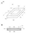
図1は、実施形態に係るイヤホン装置(イヤホン装置1)の外観構成例を示す図である。実施形態に係るイヤホン装置1は、例えば、携帯型ミュージックプレーヤやスマートフォン等(これらは図示せず)から無線伝送されるオーディオ信号を再生する。無線伝送の通信規格としては、Bluetooth(登録商標)や無線LAN(Local Area Network)が挙げられるが、これらに限定されることはない。また、イヤホン装置1は、ケーブルを介して伝送されるオーディオ信号を再生する装置であってもよい。[Example of external configuration of earphones]
FIG. 1 is a diagram showing an example of the external configuration of an earphone device (earphone device 1) according to an embodiment. The
イヤホン装置1は、例えば、筐体としてのハウジング2と、ハウジング2から延在する略円筒状の音導管3と、イヤピース4と、風検出用マイク5とを有する。 The
ハウジング2は、略球形状若しくは略円筒状のベース2Aと、ベース2Aの所定箇所(例えば、図1における右側下部)からやや突設する突設部2Bを有している。ベース2A及び突設部2Bは、例えば一体的に成形されるが、別々の部材として構成され、それらが取り付けられた構成であってもよい。ハウジング2は、例えば、ABS(Acrylonitrile Butadiene Styrene)樹脂により構成される。ベース2A及び突設部2B内には、互いに連通する内部空間が形成されており、例えばベース2Aの内部空間に、イヤホン装置1の電源となるバッテリーや、無線通信用の回路、音声処理用の回路等が収納されている(詳細は後述する。)。 The
突設部2Bの先端の端面には孔部が形成されており、当該孔部からはハウジング2の外側に向かって音導管3が延在している。音導管3は、例えば、ABS樹脂により構成されており、ハウジング2と一体的に成形される。音導管3は、ハウジング2と別体とされ、ハウジング2に取り付けられる構成であってもよい。音導管3は、内部空間を有する円筒状の形状を有し、開口を有する音導管端部3Aを有している。ユーザーの耳にイヤホン装置1が装着された際、音導管端部3Aからユーザーの耳内へ音が導出されるように構成されている。 A hole is formed in the end surface of the tip of the
詳細は後述するが、音導管3内には、MEMSデバイスが収納されている。当該MEMSデバイスには、MEMSドライバー、MEMSマイク、及び、MEMS生体センサーの少なくとも一つが含まれる。本実施形態は、MEMSデバイスにMEMSドライバー及びMEMSマイクが含まれる例である。例えば、無線伝送されたオーディオ信号に基づいて、MEMSドライバーにおける振動板が振動する。振動板が振動することでオーディオ信号に対応する音が生成され、生成された音が、音導管端部3Aからユーザーの耳内へ再生される。 Although details will be described later, a MEMS device is housed within the
イヤピース4は、材質としてシリコンゴムやウレタン系樹脂やアクリル系樹脂等が用いられたものであり、弾性変形な装着部材である。イヤピース4は、内部に孔部を有しており、図1に示すように、当該孔部に音導管3が挿入されることにより、イヤピース4が音導管3の外側に装着される。イヤピース4は弾性変形が可能であるため、音導管3への挿入時にやや径が大きくなり、イヤピース4をスムーズに音導管3に挿入できる。なお、イヤピース4が、音導管3だけでなく、突設部2Bの一部の外側までを覆うようにしてもよい。イヤピース4は、先端に開口を有しており、音導管端部3Aから放出された音が耳内に向かうことを阻害しないように構成される。イヤピース4が開口を有さずにメッシュ状とされた構成でもよい。また、ユーザーの耳にイヤホン装置1が装着された場合、イヤピース4が弾性変形することでユーザーの耳の外耳道に密着する。これにより、音導管3から再生される音を外部に漏らさないようにすることができる。さらに、イヤピース4を用いることにより、音導管3が外耳道に直接、接することでユーザーに不快感や痛みを与えることを防止することができる。 The
風検出用マイク5は、イヤホン装置1の周囲の風を検出するマイクである。風検出用マイク5により風が検知されると、フィードフォワード方式のノイズキャンセル用に用いられるマイクがオフに制御され、風のノイズが自動的に低減される。なお、風検出用マイク5はなくてもよい。 The
[MEMSデバイスの一例]
次に、本実施形態に係るMEMSデバイスの一例である、MEMSドライバー(MEMSドライバー10)及びMEMSマイク(MEMSマイク20)について説明する。なお、本明細書においてMEMSデバイスとは、半導体素子の製造プロセスを応用した微細加工技術(MEMSプロセス)により形成されるデバイスである。また、本明細書におけるMEMSデバイスは、構成の一部に、MEMSプロセスで形成されない機構部品を含んでもよい。但し、MEMSデバイス全体をより小型化する観点からは、MEMSデバイス全体がMEMSプロセスで自動で形成されたものであることが好ましい。[Example of MEMS device]
Next, a MEMS driver (MEMS driver 10) and a MEMS microphone (MEMS microphone 20), which are examples of the MEMS device according to the present embodiment, will be described. Note that in this specification, a MEMS device is a device formed by microfabrication technology (MEMS process) applying a semiconductor element manufacturing process. Further, the MEMS device in this specification may include, as part of the configuration, a mechanical component that is not formed by the MEMS process. However, from the viewpoint of further downsizing the entire MEMS device, it is preferable that the entire MEMS device be automatically formed by a MEMS process.
MEMSプロセスの一例について説明する。MEMSプロセスは、例えば、下記の工程を含む。
S1 成膜工程:シリコン等の基板に、マスク材となる薄膜を成膜する。
S2 フォトリソグラフィ工程:上記薄膜上に、レジスト(感光性樹脂)を塗布又は貼付け、フォトマスクを介した光照射によりパターンを形成する。
S3 エッチング工程:薄膜やシリコン基板などの不要部分をガスや薬液を使って削り取る。
S4 接合工程:複数基板を貼り合わせる。
S5 切断(ダイシング)工程とパッケージング工程を行うことでMEMSデバイスが完成する。
なお、上記MEMSプロセスは一例であり、一部の工程が省略されたり、他の工程が追加されてもよい。An example of a MEMS process will be described. The MEMS process includes, for example, the following steps.
S1 Film forming process: A thin film to be a mask material is formed on a substrate such as silicon.
S2 Photolithography step: A resist (photosensitive resin) is applied or pasted on the thin film, and a pattern is formed by irradiating light through a photomask.
S3 Etching process: Remove unnecessary parts such as thin films and silicon substrates using gas or chemicals.
S4 Bonding process: Bonding multiple substrates together.
S5 A MEMS device is completed by performing a cutting (dicing) process and a packaging process.
Note that the above MEMS process is an example, and some steps may be omitted or other steps may be added.
一般的なダイナミック型のドライバーは機構部品を組み立てることにより形成される。係るダイナミック型のドライバーは、個々の部品の微細化や組み立て工程の限界があり、結果的に小型化に制限がある。MEMSドライバーは、MEMSプロセスのみで生産可能であることで、小型化(微細化)が可能となる利点が得られる。また、自動で且つ大量の生産が可能となることで価格の優位性が得られる。これらの利点は、MEMSドライバーだけでなく、MEMSマイクやMEMS生体センサーについても言える。 A typical dynamic driver is formed by assembling mechanical parts. Such dynamic drivers have limitations in miniaturization of individual components and assembly processes, and as a result, there are limits to miniaturization. The MEMS driver has the advantage of being able to be manufactured using only the MEMS process, which allows for miniaturization (miniaturization). Furthermore, automatic mass production is possible, which provides a price advantage. These advantages apply not only to MEMS drivers but also to MEMS microphones and MEMS biosensors.
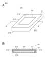
図2Aは、本実施形態に係るMEMSドライバー10の外観例を示し、図2Bは、図2AにおけるA-A線でMEMSドライバー10を切断した場合の断面を示す。図2Aに示すように、本実施形態に係るMEMSドライバー10は、概略的には直方体状(チップ形状)の筐体11を有している。筐体11は、上面11Aと、上面11Aとは反対側の底面11Bとを有している。上面11Aは図2Aにおける上側の主面(他の面に対して相対的に面積が大きい面)であり、底面11Bは図2Aにおける下側の主面である。上面11Aには、音孔として機能する孔部12A(第1孔部の一例)が形成されている。また、底面11Bには、音孔として機能する孔部12Bが形成されている。孔部12A及び孔部12Bは、例えば、矩形状の形状を有する孔部である。 FIG. 2A shows an example of the external appearance of the
図2Bに示すように、筐体11内には、振動板14が設けられている。振動板14は、図2A及び図2Bにおける左右の側面11C、11Dに架け渡されるようにして、支持部材等により支持されている。上述したように、MEMSドライバー10の各構成がMEMSプロセスにより形成される。振動板14が、MEMSドライバー10に供給されたオーディオ信号に基づいて振動することによりオーディオ信号に対応する音が生成される。生成された音が孔部12Aから放出される。また、振動板14が振動することにより生成され、孔部12Aから放出される音とは逆相の音が、孔部12Bから放出される。 As shown in FIG. 2B, a
図3Aは、本実施形態に係るMEMSマイク20の外観例を示し、図3Bは、図3AにおけるB-B線でMEMSマイク20を切断した場合の断面を示す。図3Aに示すように、本実施形態に係るMEMSマイク20は、概略的には直方体状(チップ形状)の筐体21を有している。筐体21の例えば上面21Aには、音孔として機能する孔部22(第2孔部の一例)が形成されている。孔部22は、例えば、矩形状の形状を有する孔部である。図3Bに示すように、筐体21内には、振動板24が設けられている。振動板24は、図3A及び図3Bにおける左右の側面21C、21Dに架け渡されるようにして、支持部材等により支持されている。上述したように、MEMSマイク20の各構成が、MEMSプロセスにより形成される。 FIG. 3A shows an example of the external appearance of the
MEMSマイク20は、上述したMEMSドライバー10から再生される再生音を収音するマイクである。すなわち、MEMSドライバー10の孔部12Aから放出された再生音が、MEMSマイク20の孔部22を介して音が筐体21内に取り込まれる。筐体21内に取り込まれた音によって振動板24が振動することで、MEMSドライバー10からの再生音が収音、検出される。なお、MEMSマイク20により収音される音は、MEMSドライバー10から再生される音だけでなくノイズも含み得る。 The
MEMSマイク20は、例えば、フィードバック方式でノイズキャンセルを行うためのフィードバックノイズキャンセル用マイクとして用いられる。MEMSマイク20により収音され、ノイズを含み得る音の信号と逆相の信号が、ノイズキャンセル信号として生成される。ノイズキャンセル信号を用いた公知のノイズキャンセル処理が行われることで、MEMSドライバー10から再生される音に含まれ得るノイズが除去又は低減される。 The
なお、MEMSドライバー10及びMEMSマイク20としては、上述した構成以外の公知のデバイスも適用可能である。 Note that as the
[イヤホン装置の内部構成例]
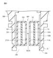
次に、図4及び図5を参照して、本実施形態に係るイヤホン装置1の内部構成例について説明する。図4に示すように、本実施形態に係る音導管3は、内部空間3Sを有している。内部空間3Sの一方はハウジング2の内部空間と連通しており、内部空間3Sの他方は、音導管端部3Aとなっている。内部空間3Sに対して、MEMSドライバー10及びMEMSマイク20が収納される。例えば、MEMSドライバー10の上面11AとMEMSマイク20の上面21Aとが対向するようにして、且つ、上面11Aと上面21Aとの間に間隙(後述する間隙SP)が形成されるようにして、MEMSドライバー10及びMEMSマイク20が内部空間3Sに収納される。上述したように、MEMSドライバー10及びMEMSマイク20は小型化が可能であるため、比較的径が小さい音導管3(例えば、径が数mm程度の音導管)内であっても両者を収納できる。[Example of internal configuration of earphone device]
Next, an example of the internal configuration of the
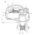
図5は、本実施形態に係るイヤホン装置1の詳細な内部構成例を示す断面図である。なお、図5及び図6の断面図は、イヤピース4が装着されていない状態の断面図である。ベース2A内には、例えば、回路部31、フィードフォワード方式のノイズキャンセルを行うためのフィードフォワードノイズキャンセル用マイク32、バッテリー33が収納されている。 FIG. 5 is a sectional view showing a detailed internal configuration example of the
回路部31は、スマートフォンや携帯型オーディオプレーヤー等の外部装置からオーディオ信号を受信する通信回路、公知の音響処理を行う音響処理回路、オーディオ信号を増幅するアンプ、ノイズキャンセル処理を行う回路等を総称したものである。回路部31等のイヤホン装置1の各部は、バッテリー33から供給される電力に基づいて動作する。回路部31のノイズキャンセルを行う回路は、フィードバックノイズキャンセル用マイクであるMEMSマイク20や、フィードフォワードノイズキャンセル用マイク32に接続される。また、回路部31は、MEMSドライバー10とも接続されており、回路部31で外部装置から受信されたオーディオ信号が適宜、増幅された上でMEMSドライバー10に供給されるように構成されている。なお、これらの接続パターンの図示は適宜、簡略又は省略している。 The
上述したように、音導管3の内部空間3Sに、MEMSドライバー10及びMEMSマイク20が収納される。MEMSドライバー10及びMEMSマイク20は、音導管3の内面に接着等によって取り付けられてもよいし、適宜な支持部材によって取り付けられてもよいし、嵌め込まれるようにしてもよい。MEMSドライバー10及びMEMSマイク20が内部空間3Sに収納された状態では、MEMSドライバー10の上面11AとMEMSマイク20の上面21Aとの間に間隙SPが形成される。MEMSドライバー10から再生された再生音は、間隙SP及び音導管3の開放端を介してユーザーの鼓膜に到達する。また、MEMSドライバー10から再生された再生音は、間隙SPを介してMEMSマイク20に到達し検出される。なお、MEMSドライバー10の孔部12Bは音導管3の内面と対向しているため、MEMSドライバー10の再生音と逆相の音が鼓膜側に伝搬することは抑制される。 As described above, the
MEMSドライバー10及びMEMSマイク20を音導管3内に収納できるので、イヤホン装置1を小型化できる。例えば、従来は、ダイナミック型のドライバーをハウジング2内に収納するため、ハウジング2が一定以上の容積となる必要があったが、ドライバーに係る構成を音導管3内に収納できるため、ハウジング2を小型化でき、且つ、イヤホン装置1全体を小型化できる。すなわち、音響処理装置が有するMEMSデバイスの効果的な配置を実現できる。また、イヤホン装置1を小型化できるので音響的負荷となる外耳道内容積を最小化できる。すなわち、イヤホン装置1を比較的耳の奥に挿入することができるので、振動板14から外耳道を経て鼓膜に至る容積の空気(音響的な負荷)を小さくすることができる。これにより、振動板14の一定の振幅に対して空気の容積が小さくできるので、発生する交流気圧を大きくすることができ、イヤホン装置1を高感度なトランスデューサーとすることができる。さらに、MEMSドライバー10は小型化されたデバイスであることから、デバイス内の比較的少量の空気を振動させることで音を再生できることになり、感度を向上させることができる。 Since the
さらに、本実施形態に係る構成によれば、MEMSドライバー10と、フィードバックノイズキャンセル用マイクであるMEMSマイク20とを近接して配置することができる。すなわち、図6の部分拡大図における矢印で示すように、MEMSドライバー10で再生された再生音を、MEMSドライバー10の近くに配置されるMEMSマイク20によって収音でき、再生音の伝搬距離である音響的な流路SCAを短くすることができる。 Furthermore, according to the configuration according to the present embodiment, the
図7は、一般的なイヤホン装置の内部構成例を示す。図7に示すイヤホン装置はハウジング内にダイナミック型のドライバーユニット41を有する。ドライバーユニット41に近接する位置にはフィードバックノイズキャンセル用マイク42が配置される。ドライバーユニット41が収納される壁部43には、フィードバックノイズキャンセル用マイク42の開口に繋がる孔部44が形成されている。図7の矢印で模式的に示すように、ドライバーユニット41で再生された再生音は、壁部43の孔部44を介してフィードバックノイズキャンセル用マイク42に到達する。一般的なイヤホン装置の場合は、ドライバーユニット41から再生された再生音がフィードバックノイズキャンセル用マイク42に到達するまでの音響的な流路SCBの長さが大きくなってしまう。例えば、音響的な流路SCBの長さが10mm程度になってしまう。 FIG. 7 shows an example of the internal configuration of a general earphone device. The earphone device shown in FIG. 7 has a
音響的な流路SCBの長さが10mm程度になると、例えば5kHzの再生音がフィードバックノイズキャンセル用マイク42に到達するまでに、位相が60度程度、回転(反転)してしまう。位相の回転が60度程度の場合は、フィードバック方式のノイズキャンセル効果が極めて小さくなってしまう。 When the length of the acoustic flow path SCB is about 10 mm, the phase of the reproduced sound of, for example, 5 kHz will be rotated (inverted) by about 60 degrees before it reaches the feedback
係る再生音の位相の回転を防止し、ノイズキャンセルの効果を得るためには、再生音の音響的な流路の長さを極力、小さくすることが望まれる。本実施形態の構成では、MEMSドライバー10及びMEMSマイク20を小型化できるので、音導管3内に両者を近接して配置することができる。すなわち、MEMSドライバー10から再生された再生音の音響的な流路の長さを小さくできる。例えば、本実施形態に係る構成では、MEMSドライバー10から再生された再生音がMEMSマイク20に到達するまでの音響的な流路SCAの長さを3mm以下とすることができる。音響的な流路SCAの長さが3mm以下の場合、例えば5kHzの再生音の位相の回転は20度以下となり、フィードバック方式のノイズキャンセルの効果を十分に得られる。なお、音響的な流路SCAの長さは、例えば、MEMSドライバー10の孔部12Aの開放端面からMEMSマイク20の振動板24までの、音の伝搬空間における最短距離により規定することができる。 In order to prevent such phase rotation of the reproduced sound and obtain a noise canceling effect, it is desirable to reduce the length of the acoustic flow path of the reproduced sound as much as possible. In the configuration of this embodiment, the
<第2の実施形態>
次に、第2の実施形態について説明する。なお、第2の実施形態の説明において、上述した説明における同一または同質の構成については同一の参照符号を付し、重複した説明が適宜、省略される。また、特に断らない限り、第1の実施形態で説明した事項は第2の実施形態に対して適用することができる。<Second embodiment>
Next, a second embodiment will be described. In addition, in the description of the second embodiment, the same or homogeneous configurations in the above description are given the same reference numerals, and redundant descriptions will be omitted as appropriate. Further, unless otherwise specified, the matters described in the first embodiment can be applied to the second embodiment.
第2の実施形態では、音導管3内に収納されるMEMSデバイスに、MEMSドライバー10、MEMSマイク20、及び、MEMS生体センサーが含まれる。MEMS生体センサーとは、上述したMEMSプロセスによって形成された生体センサーである。MEMS生体センサーとしては、例えば、血流センサー、心拍・脈拍センサー、脳波センサー、体温センサーが挙げられる。MEMS生体センサーは、前述した生体データ以外の生体データを取得するセンサーであってもよい。 In the second embodiment, the MEMS devices housed in the
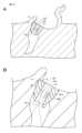
図8は、一般的な人間の外耳道ECの構造を示す。外耳道ECは、入口から10mmほどの深さで第1カーブC1に突き当たり、更に10mmほど先で第2カーブC2を経由して鼓膜DRPに至る。イヤピース4は、外耳道EC入口からこの第1カーブC1の間に挿入され、イヤピース4の先端の開口4A(図9及び図10参照)は第1カーブC1付近の耳壁と対向する。人間の耳壁に皮下組織には多くの血管が通っており、人体の血流を観測するには好適な部位である。 FIG. 8 shows the structure of a typical human external auditory canal EC. The ear canal EC hits the first curve C1 at a depth of about 10 mm from the entrance, and reaches the eardrum DRP about 10 mm further ahead via the second curve C2. The
血流を測定する方式としては、血中のヘモグロビンを観測する方式が挙げられる。係る方式の場合、血流センサーは、血流部分に赤外線を照射する光源と、反射光を受光する受光素子とを有する。原理的には、血流中のヘモグロビンに特定波長の光が吸収されるため、反射光の波長を観測することにより、ヘモグロビン量の変化(血管の収縮すなわち脈拍)を確認することができる。 A method for measuring blood flow includes a method for observing hemoglobin in blood. In the case of such a system, the blood flow sensor includes a light source that irradiates the blood flow portion with infrared rays and a light receiving element that receives reflected light. In principle, light of a specific wavelength is absorbed by hemoglobin in the bloodstream, so by observing the wavelength of reflected light, changes in the amount of hemoglobin (constriction of blood vessels, ie, pulse) can be confirmed.
図9Aに示すように、イヤピース4が装着される音導管3内にMEMSドライバー10、MEMSマイク20、及び、MEMS生体センサーの一例である血流センサー50が収納される。一例として、音導管3の内面に接するようにMEMSドライバー10及びMEMSマイク20がそれぞれ配置され、その間に、血流センサー50が配置される。なお、図9A及び図9Bでは、イヤホン装置の図示を簡略化している。また、再生音の鼓膜に向かう伝搬経路(空間)やMEMSマイク20に向かう伝搬経路の図示は適宜、省略している。また、血流センサー50の配置位置は、MEMSドライバー10及びMEMSマイク20の間以外の位置、例えば、MEMSドライバー10やMEMSマイク20の外耳道EC内に向く面であってもよい。 As shown in FIG. 9A, a
図9Bに示すように、血流センサー50は、光源51と受光素子52とを有している。光源51と受光素子52は、イヤピース4の先端の開口4Aを介して、第1カーブC1付近の耳壁と対向するように配置される。光源51及び受光素子52は、不図示の配線パターンによって回路部31と接続されている。回路部31のIC(Integrated Circuit)によって光源51の発光が制御される。また、受光素子52で受光され、電気信号へと変換された信号が回路部31に供給され血流を測定するための公知の処理が回路部31のICによって行われる。なお、光源51の制御や受光素子52の受光信号を処理するICがMEMSプロセスによって血流センサー50と一体的に構成されていてもよい。 As shown in FIG. 9B, the
図9Bに示すように、光源51から出射された赤外光は第1カーブC1付近の耳壁に照射され、その反射光が受光素子52で受光される。図9Bでは、係る赤外光及び反射光が矢印により模式的に示されている。そして、上述した原理によってイヤホン装置のユーザーの血流が測定される。 As shown in FIG. 9B, the infrared light emitted from the
このように、MEMSプロセスにより形成された血流センサー50は、小型化できるため、音導管3内に血流センサー50を収納することができる。これにより、イヤホン装置を大型化することなく、イヤホン装置のユーザーの血流を効果的に測定することが可能となる。 In this way, since the
上述したように、イヤホン装置は補聴器であってもよい。この場合、聴力に不自由を感じている高齢者が常時装着すると考えられる補聴器で、聴力を補いつつ血流を観測し続けることができる。得られた血流に関するデータは、補聴器から高齢者のスマートフォンや健康状態をモニタリングするサーバー等に送信されてもよい。血流に関するデータが外部装置に送信されることにより、健康状態のモニタリングシステムや、血流に異常が認められた場合に高齢者の家族や介護者に異常を通報するシステム等を構築することができる。 As mentioned above, the earphone device may be a hearing aid. In this case, hearing aids, which are thought to be worn by elderly people with hearing loss at all times, can supplement their hearing while continuing to monitor blood flow. The obtained data regarding blood flow may be transmitted from the hearing aid to the elderly person's smartphone, a server that monitors the health condition, and the like. By sending data related to blood flow to an external device, it is possible to build a health monitoring system or a system that notifies the family or caregiver of an elderly person if an abnormality is detected in blood flow. can.
MEMS生体センサーは、血流センサー50ではなく、体温センサーであってもよい。耳道内は体表温度よりも体内温度に近く、外部温度の影響を受けずに一定であることから、非接触式の体温計が実用化されている。原理的には、耳道内から体温に相応する赤外線が放出されており、この赤外線を赤外線受光素子で検出することにより体温の測定が可能となる。 The MEMS biological sensor may be a body temperature sensor instead of the
図10Aに示すように、イヤピース4が装着される音導管3内にMEMSドライバー10、MEMSマイク20、及び、MEMS生体センサーの一例である体温センサー60が収納される。一例として、音導管3の内面に接するようにMEMSドライバー10及びMEMSマイク20がそれぞれ配置され、その間に、体温センサー60が配置される。なお、図10A及び図10Bでは、イヤホン装置の図示を簡略化している。また、再生音の鼓膜に向かう伝搬経路(空間)やMEMSマイク20に向かう伝搬経路の図示は適宜、省略している。また、体温センサー60の配置位置は、MEMSドライバー10及びMEMSマイク20の間以外の位置、例えば、MEMSドライバー10やMEMSマイク20の外耳道EC内に向く面であってもよい。 As shown in FIG. 10A, a
図10Bに示すように、体温センサー60は、赤外線受光素子61を有している。赤外線受光素子61は、イヤピース4の先端の開口4Aを介して、第1カーブC1付近の耳壁と対向するように配置される。赤外線受光素子61により耳壁から放出される赤外光(図10Bにおいて矢印により模式的に示す)が受光される。赤外線受光素子61は、不図示の配線パターンによって回路部31と接続されている。赤外線受光素子61で受光され、電気信号へと変換された信号が回路部31に供給される。そして、体温を測定するための公知の処理が回路部31のICによって行われる。なお、赤外線受光素子61の受光信号を処理するICがMEMSプロセスによって体温センサー60と一体的に構成されていてもよい。 As shown in FIG. 10B, the
このように、MEMSプロセスにより形成された体温センサー60は、小型化できるため、音導管3内に体温センサー60を収納することができる。これにより、イヤホン装置を大型化することなく、イヤホン装置のユーザーの体温を効果的に測定することが可能となる。 In this way, the
イヤホン装置による音楽聴取時のみならず、イヤホン装置を常に装着しながら、周囲との会話やインターネット等のネットワークを介して音声情報を受け取る生活スタイルが今後普及すると考えられる。この場合に、健康の基本情報である体温が継続的に計測できることで、イヤホン装置のユーザーのライフサイクルにおける健康管理だけでなく、活動内容に連携した様々な情報サービスの提供をユーザーが受けることが可能となる。例えば、体温が高いときにイヤホン装置を介して、音声による医療情報の提供や気分を落ち着かせる音楽の提供等のサービスをユーザーが受けることが可能となる。 It is thought that a lifestyle will become popular in the future, not only when listening to music using an earphone device, but also by constantly wearing the earphone device while receiving audio information through conversations with people around you and networks such as the Internet. In this case, by being able to continuously measure body temperature, which is basic health information, users of the earphone device can not only manage their health throughout their life cycle, but also receive various information services linked to their activities. It becomes possible. For example, when the user's body temperature is high, the user can receive services such as audio medical information or soothing music through the earphone device.
なお、上述した例では、MEMS生体センサーの一例として、血流センサー50又は体温センサー60を挙げたが、MEMS生体センサーに両方が含まれてもよいし、血流センサー50及び体温センサー60ではなく、他の生体センサー(例えば、血圧センサーや心拍・脈拍センサー、脳波センサー)であってもよいし、これらを組み合わせたものであってもよい。MEMS生体センサーは小型化が可能であることから、複数のMEMS生体センサーを音導管3内に収納することができる。 In the above example, the
<変形例>
以上、本開示の実施形態について具体的に説明したが、本開示の内容は上述した実施形態に限定されるものではなく、本開示の技術的思想に基づく各種の変形が可能である。<Modified example>
Although the embodiments of the present disclosure have been specifically described above, the content of the present disclosure is not limited to the embodiments described above, and various modifications based on the technical idea of the present disclosure are possible.
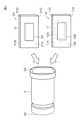
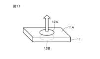
MEMSデバイスの形状は、実施形態で説明した以外の形状であってもよい。例えば、MEMSドライバー10の筐体11は、円筒形状であってもよい。また、図11に示すように、孔部12A及び孔部12Bの形状は矩形状に限定されることはなく円形状でもよいし、他の形状、例えば、楕円形状、多角形状等であってもよい。孔部22の形状についても同様である。 The shape of the MEMS device may be other than those described in the embodiments. For example, the
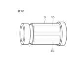
上述した実施形態では、MEMSドライバー及びMEMSマイクが別々のMEMSデバイスとして説明したが、MEMSドライバー及びMEMSマイクが一つのMEMSプロセスによって一体的に構成されたMEMSデバイスであってもよい。また、MEMSドライバー、MEMSマイク、及び、MEMS生体センサーが一つのMEMSプロセスによって一体的に構成されたMEMSデバイスであってもよい。また、図12に示すように、音導管3、MEMSドライバー10、及び、MEMSマイク20が、一つのMEMSプロセスによって一体的に構成されたMEMSデバイスであってもよい。例えば、シリコン基板等を形状加工することに得られた音導管3の内面に、MEMSプロセスによってMEMSドライバー10及びMEMSマイク20が形成されたものであってもよい。また、図12に示す構成に対してMEMS生体センサーがさらに一体化された構成を有するMEMSデバイスであってもよい。 In the embodiments described above, the MEMS driver and the MEMS microphone are described as separate MEMS devices, but the MEMS driver and the MEMS microphone may be a MEMS device integrally configured by one MEMS process. Alternatively, the MEMS device may be a MEMS device in which a MEMS driver, a MEMS microphone, and a MEMS biosensor are integrally configured by one MEMS process. Further, as shown in FIG. 12, the
MEMSドライバー、MEMSマイク、及び、MEMS生体センサーの配置箇所は実施形態で説明した例に限定されるものではない。図13は、MEMSドライバー10、MEMSマイク20、及び、MEMS生体センサー(例えば、上述した血流センサー50や体温センサー60)の本変形例に係る配置例を説明するための図である。なお、図13は、音導管端部3A側から音導管3の内部空間3Sを視た場合のMEMSドライバー10等の配置例(上面視図)を示す。 The locations where the MEMS driver, MEMS microphone, and MEMS biosensor are arranged are not limited to the examples described in the embodiments. FIG. 13 is a diagram for explaining an example of the arrangement of the
図13に示すように、MEMSドライバー10とMEMSマイク20とが、両者の間に間隙SPAを形成するようにして配置される。MEMS生体センサーは、間隙SPA以外の箇所に配置されてもよい。例えば、MEMS生体センサーが、内部空間3SにおいてMEMSドライバー10及びMEMSマイク20の配置箇所よりも下側の箇所に配置されてもよい。なお、MEMS生体センサーが、内部空間3SにおいてMEMSドライバー10及びMEMSマイク20の配置箇所よりも上側の箇所に配置されてもよい。また、MEMSドライバー10及びMEMSマイク20の配置箇所の上下に異なるMEMS生体センサーがそれぞれ配置されてもよい。 As shown in FIG. 13, the
MEMSデバイスの組み合わせは、実施形態で説明した組み合わせが好ましいものの、例えば、音導管内に収納されるMEMSデバイスが、MEMSドライバー、MEMSマイク、及び、MEMS生体センサーの何れか一つであってもよい。 Although the combination of MEMS devices described in the embodiment is preferable, for example, the MEMS device housed in the sound pipe may be any one of a MEMS driver, a MEMS microphone, and a MEMS biosensor. .
ハウジング2や音導管3の材料としてはABS樹脂に限らず、例えば、ポリプロピレンやポリスチレン等の他の種々の樹脂が使用されてもよい。また、突設部2Bの材料としてエラストマー樹脂等の柔軟性のある樹脂が使用されてもよい。この場合、突設部2Bの部分が柔軟性を有することにより、音導管3を曲げることが可能になる。これにより、ユーザーの耳にイヤホン装置を装着させる際、音導管3及びイヤピース4をより装着感の良い方向に曲げてイヤホン装置を装着させることができる。 The material of the
本開示に係る音響処理装置は、補聴器又は集音器としても構成できる。補聴器として用いる場合、自分の発した声が大きく聞こえたり、自身の咀嚼音や足の踏み込みにより伝達する音が補聴器内にこもる現象が生じる。これらの現象は、オクルージョンと称される。第1の実施形態等で説明したように、音導管内にMEMSドライバー及びMEMSマイクを収納することでノイズキャンセルの性能を向上させることができる。ノイズキャンセルの性能が向上することで、上述したオクルージョンを抑制でき、性能に優れた補聴器を提供できる。 The sound processing device according to the present disclosure can also be configured as a hearing aid or a sound collector. When used as a hearing aid, phenomena such as the sound of one's own voice being heard louder or the sounds transmitted by one's own chewing or foot stepping becoming trapped inside the hearing aid. These phenomena are called occlusions. As described in the first embodiment and the like, noise canceling performance can be improved by housing the MEMS driver and the MEMS microphone within the sound pipe. By improving the noise cancellation performance, the above-mentioned occlusion can be suppressed, and a hearing aid with excellent performance can be provided.
上述した実施形態において挙げた構成、方法、工程、形状、材料及び数値などはあくまでも例に過ぎず、必要に応じてこれと異なる構成、方法、工程、形状、材料及び数値などを用いてもよい。上述した実施形態及び変形例は、適宜組み合わせることができる。 The configurations, methods, processes, shapes, materials, numerical values, etc. mentioned in the embodiments described above are merely examples, and different configurations, methods, processes, shapes, materials, numerical values, etc. may be used as necessary. . The embodiments and modifications described above can be combined as appropriate.
本開示は、以下の構成も採ることができる。
(1)
筐体と、
前記筐体から延在する音導管と、
前記音導管内に収納されるMEMSデバイスと
を有する
音響処理装置。
(2)
前記MEMSデバイスは、前記MEMSドライバー、前記MEMSマイク、及び、前記MEMS生体センサーの少なくとも一つを含む
(1)に記載の音響処理装置。
(3)
前記MEMSデバイスは、MEMSドライバー及びMEMSマイクを含む
(2)に記載の音響処理装置。
(4)
前記MEMSドライバーは、第1孔部を有し、
前記MEMSマイクは、第2孔部を有し、
前記第1孔部と前記第2孔部との間の距離が3mm以下である
(3)に記載の音響処理装置。
(5)
前記MEMSドライバーと前記MEMSマイクとが一体的に構成された
(3)又は(4)に記載の音響処理装置。
(6)
前記MEMSマイクは、前記MEMSドライバーから再生される音を収音するマイクである
(3)から(5)までの何れかに記載の音響処理装置。
(7)
前記MEMSデバイスは、前記MEMSドライバー、前記MEMSマイク、及び、前記MEMS生体センサーを含む
(2)に記載の音響処理装置。
(8)
前記MEMSドライバー、前記MEMSマイク、及び、前記MEMS生体センサーが一体的に構成されている
(7)に記載の音響処理装置。
(9)
前記MEMSデバイスは、前記MEMS生体センサーを含み、
前記MEMS生体センサーは、血流センサー及び体温センサーの少なくとも一方を含む
(2)から(8)までの何れかに記載の音響処理装置。
(10)
前記音導管及び前記MEMSデバイスが一体的とされたMEMSデバイスとして構成される
(1)から(9)までの何れかに記載の音響処理装置。
(11)
前記音導管の外側に装着され、弾性変形可能な装着部材を有する
(1)から(10)までの何れかに記載の音響処理装置。
(12)
前記音導管は、略円筒状の形状を有する
(1)から(11)までの何れかに記載の音響処理装置。The present disclosure can also take the following configuration.
(1)
A casing and
a sound conduit extending from the housing;
A sound processing device comprising: a MEMS device housed in the sound pipe.
(2)
The acoustic processing device according to (1), wherein the MEMS device includes at least one of the MEMS driver, the MEMS microphone, and the MEMS biosensor.
(3)
The sound processing device according to (2), wherein the MEMS device includes a MEMS driver and a MEMS microphone.
(4)
The MEMS driver has a first hole,
The MEMS microphone has a second hole,
The sound processing device according to (3), wherein the distance between the first hole and the second hole is 3 mm or less.
(5)
The sound processing device according to (3) or (4), wherein the MEMS driver and the MEMS microphone are integrally configured.
(6)
The sound processing device according to any one of (3) to (5), wherein the MEMS microphone is a microphone that picks up sound reproduced from the MEMS driver.
(7)
The acoustic processing device according to (2), wherein the MEMS device includes the MEMS driver, the MEMS microphone, and the MEMS biosensor.
(8)
The acoustic processing device according to (7), wherein the MEMS driver, the MEMS microphone, and the MEMS biosensor are integrally configured.
(9)
The MEMS device includes the MEMS biosensor,
The acoustic processing device according to any one of (2) to (8), wherein the MEMS biosensor includes at least one of a blood flow sensor and a body temperature sensor.
(10)
The sound processing device according to any one of (1) to (9), wherein the sound pipe and the MEMS device are configured as an integrated MEMS device.
(11)
The sound processing device according to any one of (1) to (10), including an elastically deformable mounting member that is mounted on the outside of the sound pipe.
(12)
The sound processing device according to any one of (1) to (11), wherein the sound pipe has a substantially cylindrical shape.
1・・・イヤホン装置
2・・・筐体
3・・・音導管
4・・・イヤピース
10・・・MEMSドライバー
20・・・MEMSマイク
50・・・血流センサー
60・・・体温センサー1...
Claims (12)
Translated fromJapanese前記筐体から延在する音導管と、
前記音導管内に収納されるMEMSデバイスと
を有する
音響処理装置。A casing and
a sound conduit extending from the housing;
A sound processing device comprising: a MEMS device housed in the sound pipe.
請求項1に記載の音響処理装置。The acoustic processing device according to claim 1, wherein the MEMS device includes at least one of a MEMS driver, a MEMS microphone, and a MEMS biosensor.
請求項2に記載の音響処理装置。The acoustic processing apparatus according to claim 2, wherein the MEMS device includes the MEMS driver and the MEMS microphone.
前記MEMSマイクは、第2孔部を有し、
前記第1孔部と前記第2孔部との間の距離が3mm以下である
請求項3に記載の音響処理装置。The MEMS driver has a first hole,
The MEMS microphone has a second hole,
The sound processing device according to claim 3, wherein a distance between the first hole and the second hole is 3 mm or less.
請求項3に記載の音響処理装置。The sound processing device according to claim 3, wherein the MEMS driver and the MEMS microphone are integrally configured.
請求項3に記載の音響処理装置。The sound processing device according to claim 3, wherein the MEMS microphone is a microphone that collects sound reproduced from the MEMS driver.
請求項2に記載の音響処理装置。The acoustic processing device according to claim 2, wherein the MEMS device includes the MEMS driver, the MEMS microphone, and the MEMS biosensor.
請求項7に記載の音響処理装置。The acoustic processing device according to claim 7, wherein the MEMS driver, the MEMS microphone, and the MEMS biosensor are integrally configured.
前記MEMS生体センサーは、血流センサー及び体温センサーの少なくとも一方を含む
請求項2に記載の音響処理装置。The MEMS device includes the MEMS biosensor,
The acoustic processing device according to claim 2, wherein the MEMS biosensor includes at least one of a blood flow sensor and a body temperature sensor.
請求項1に記載の音響処理装置。The sound processing device according to claim 1, wherein the sound pipe and the MEMS device are configured as an integrated MEMS device.
請求項1に記載の音響処理装置。The sound processing device according to claim 1, further comprising an elastically deformable mounting member mounted on the outside of the sound pipe.
請求項1に記載の音響処理装置。The sound processing device according to claim 1, wherein the sound guide tube has a substantially cylindrical shape.
Priority Applications (1)
| Application Number | Priority Date | Filing Date | Title |
|---|---|---|---|
| PCT/JP2023/019891WO2023238720A1 (en) | 2022-06-06 | 2023-05-29 | Acoustic processing apparatus |
Applications Claiming Priority (2)
| Application Number | Priority Date | Filing Date | Title |
|---|---|---|---|
| JP2022091282 | 2022-06-06 | ||
| JP2022091282 | 2022-06-06 |
Publications (1)
| Publication Number | Publication Date |
|---|---|
| JP2023178938Atrue JP2023178938A (en) | 2023-12-18 |
Family
ID=89189801
Family Applications (1)
| Application Number | Title | Priority Date | Filing Date |
|---|---|---|---|
| JP2023025681APendingJP2023178938A (en) | 2022-06-06 | 2023-02-22 | Acoustic processing apparatus |
Country Status (1)
| Country | Link |
|---|---|
| JP (1) | JP2023178938A (en) |
Cited By (14)
| Publication number | Priority date | Publication date | Assignee | Title |
|---|---|---|---|---|
| JP2023174845A (en)* | 2021-03-01 | 2023-12-08 | 株式会社三洋物産 | Game machine |
| JP2023174847A (en)* | 2021-03-01 | 2023-12-08 | 株式会社三洋物産 | Game machine |
| JP2023174844A (en)* | 2021-03-01 | 2023-12-08 | 株式会社三洋物産 | Game machine |
| JP2023174846A (en)* | 2021-03-01 | 2023-12-08 | 株式会社三洋物産 | Game machine |
| JP2023174850A (en)* | 2021-03-01 | 2023-12-08 | 株式会社三洋物産 | Game machine |
| JP2023174843A (en)* | 2021-03-01 | 2023-12-08 | 株式会社三洋物産 | Game machine |
| JP2023178383A (en)* | 2021-03-01 | 2023-12-14 | 株式会社三洋物産 | Game machine |
| JP2023178384A (en)* | 2021-03-01 | 2023-12-14 | 株式会社三洋物産 | Game machine |
| JP2024026866A (en)* | 2022-07-21 | 2024-02-28 | 株式会社三洋物産 | gaming machine |
| JP2024026865A (en)* | 2022-07-21 | 2024-02-28 | 株式会社三洋物産 | Game machine |
| JP2024028536A (en)* | 2022-07-21 | 2024-03-04 | 株式会社三洋物産 | gaming machine |
| JP2024107230A (en)* | 2018-02-15 | 2024-08-08 | 株式会社三洋物産 | Gaming Machines |
| JP2024107228A (en)* | 2018-02-15 | 2024-08-08 | 株式会社三洋物産 | Gaming Machines |
| JP2024107229A (en)* | 2018-02-15 | 2024-08-08 | 株式会社三洋物産 | Gaming Machines |
- 2023
- 2023-02-22JPJP2023025681Apatent/JP2023178938A/enactivePending
Cited By (14)
| Publication number | Priority date | Publication date | Assignee | Title |
|---|---|---|---|---|
| JP2024107230A (en)* | 2018-02-15 | 2024-08-08 | 株式会社三洋物産 | Gaming Machines |
| JP2024107229A (en)* | 2018-02-15 | 2024-08-08 | 株式会社三洋物産 | Gaming Machines |
| JP2024107228A (en)* | 2018-02-15 | 2024-08-08 | 株式会社三洋物産 | Gaming Machines |
| JP2023178383A (en)* | 2021-03-01 | 2023-12-14 | 株式会社三洋物産 | Game machine |
| JP2023174850A (en)* | 2021-03-01 | 2023-12-08 | 株式会社三洋物産 | Game machine |
| JP2023174843A (en)* | 2021-03-01 | 2023-12-08 | 株式会社三洋物産 | Game machine |
| JP2023174845A (en)* | 2021-03-01 | 2023-12-08 | 株式会社三洋物産 | Game machine |
| JP2023178384A (en)* | 2021-03-01 | 2023-12-14 | 株式会社三洋物産 | Game machine |
| JP2023174846A (en)* | 2021-03-01 | 2023-12-08 | 株式会社三洋物産 | Game machine |
| JP2023174844A (en)* | 2021-03-01 | 2023-12-08 | 株式会社三洋物産 | Game machine |
| JP2023174847A (en)* | 2021-03-01 | 2023-12-08 | 株式会社三洋物産 | Game machine |
| JP2024026866A (en)* | 2022-07-21 | 2024-02-28 | 株式会社三洋物産 | gaming machine |
| JP2024026865A (en)* | 2022-07-21 | 2024-02-28 | 株式会社三洋物産 | Game machine |
| JP2024028536A (en)* | 2022-07-21 | 2024-03-04 | 株式会社三洋物産 | gaming machine |
Similar Documents
| Publication | Publication Date | Title |
|---|---|---|
| JP2023178938A (en) | Acoustic processing apparatus | |
| US11350211B2 (en) | In-the-ear hearing aid device, a hearing aid, and an electro-acoustic transducer | |
| US9380374B2 (en) | Hearing assistance systems configured to detect and provide protection to the user from harmful conditions | |
| US5859916A (en) | Two stage implantable microphone | |
| JP6219889B2 (en) | Audio equipment | |
| US20080205679A1 (en) | In-Ear Auditory Device and Methods of Using Same | |
| US20110319021A1 (en) | Intra-oral tissue conduction microphone | |
| US20150319546A1 (en) | Hearing Assistance System | |
| JP2020533060A (en) | Auscultation of the body | |
| JP7284102B2 (en) | Apparatus for detecting at least one vital parameter of a human being by a sensor | |
| WO2003088841A3 (en) | Headset for measuring physiological parameters | |
| JP2008136556A (en) | Earphone apparatus | |
| US20190033505A1 (en) | Ear-worn electronic device waveguide extension for inner ear waveform transmission | |
| WO2016167877A1 (en) | Hearing assistance systems configured to detect and provide protection to the user harmful conditions | |
| JP5603789B2 (en) | Body sound acquisition device and electronic stethoscope provided with the same | |
| JP2011019799A (en) | Electronic stethoscope | |
| CN105992117A (en) | Eardrum hearing aid | |
| JP2016072798A (en) | Audio vibration output device | |
| CN208017485U (en) | Physiological Signal Measurement Device | |
| WO2023238720A1 (en) | Acoustic processing apparatus | |
| JP2016116153A (en) | Ear canal-mounted earphone microphone | |
| WO2017100484A1 (en) | Apparatus, system and method for reducing acoustic feedback interference signals | |
| CN114467311A (en) | Method and device for active noise reduction | |
| CN114900765B (en) | An audiometric earphone with intelligent noise reduction function | |
| JP2011083372A (en) | Electronic stethoscope |