JP2023177045A - Seat position estimation device, seat position estimation method and computer program for seat position estimation - Google Patents
Seat position estimation device, seat position estimation method and computer program for seat position estimationDownload PDFInfo
- Publication number
- JP2023177045A JP2023177045AJP2022089735AJP2022089735AJP2023177045AJP 2023177045 AJP2023177045 AJP 2023177045AJP 2022089735 AJP2022089735 AJP 2022089735AJP 2022089735 AJP2022089735 AJP 2022089735AJP 2023177045 AJP2023177045 AJP 2023177045A
- Authority
- JP
- Japan
- Prior art keywords
- driver
- image
- vehicle
- difference
- seat
- Prior art date
- Legal status (The legal status is an assumption and is not a legal conclusion. Google has not performed a legal analysis and makes no representation as to the accuracy of the status listed.)
- Granted
Links
Images


Classifications
- G—PHYSICS
- G06—COMPUTING OR CALCULATING; COUNTING
- G06V—IMAGE OR VIDEO RECOGNITION OR UNDERSTANDING
- G06V20/00—Scenes; Scene-specific elements
- G06V20/50—Context or environment of the image
- G06V20/59—Context or environment of the image inside of a vehicle, e.g. relating to seat occupancy, driver state or inner lighting conditions
- G06V20/597—Recognising the driver's state or behaviour, e.g. attention or drowsiness
- G—PHYSICS
- G06—COMPUTING OR CALCULATING; COUNTING
- G06T—IMAGE DATA PROCESSING OR GENERATION, IN GENERAL
- G06T7/00—Image analysis
- G06T7/70—Determining position or orientation of objects or cameras
- G06T7/73—Determining position or orientation of objects or cameras using feature-based methods
- G06T7/74—Determining position or orientation of objects or cameras using feature-based methods involving reference images or patches
- G—PHYSICS
- G06—COMPUTING OR CALCULATING; COUNTING
- G06T—IMAGE DATA PROCESSING OR GENERATION, IN GENERAL
- G06T7/00—Image analysis
- G—PHYSICS
- G06—COMPUTING OR CALCULATING; COUNTING
- G06T—IMAGE DATA PROCESSING OR GENERATION, IN GENERAL
- G06T7/00—Image analysis
- G06T7/0002—Inspection of images, e.g. flaw detection
- G—PHYSICS
- G06—COMPUTING OR CALCULATING; COUNTING
- G06T—IMAGE DATA PROCESSING OR GENERATION, IN GENERAL
- G06T7/00—Image analysis
- G06T7/10—Segmentation; Edge detection
- G06T7/11—Region-based segmentation
- G—PHYSICS
- G06—COMPUTING OR CALCULATING; COUNTING
- G06T—IMAGE DATA PROCESSING OR GENERATION, IN GENERAL
- G06T7/00—Image analysis
- G06T7/10—Segmentation; Edge detection
- G06T7/13—Edge detection
- G—PHYSICS
- G06—COMPUTING OR CALCULATING; COUNTING
- G06T—IMAGE DATA PROCESSING OR GENERATION, IN GENERAL
- G06T7/00—Image analysis
- G06T7/10—Segmentation; Edge detection
- G06T7/194—Segmentation; Edge detection involving foreground-background segmentation
- G—PHYSICS
- G06—COMPUTING OR CALCULATING; COUNTING
- G06T—IMAGE DATA PROCESSING OR GENERATION, IN GENERAL
- G06T7/00—Image analysis
- G06T7/70—Determining position or orientation of objects or cameras
- G06T7/73—Determining position or orientation of objects or cameras using feature-based methods
- G—PHYSICS
- G06—COMPUTING OR CALCULATING; COUNTING
- G06V—IMAGE OR VIDEO RECOGNITION OR UNDERSTANDING
- G06V10/00—Arrangements for image or video recognition or understanding
- G06V10/20—Image preprocessing
- G06V10/22—Image preprocessing by selection of a specific region containing or referencing a pattern; Locating or processing of specific regions to guide the detection or recognition
- G—PHYSICS
- G06—COMPUTING OR CALCULATING; COUNTING
- G06V—IMAGE OR VIDEO RECOGNITION OR UNDERSTANDING
- G06V10/00—Arrangements for image or video recognition or understanding
- G06V10/70—Arrangements for image or video recognition or understanding using pattern recognition or machine learning
- G06V10/764—Arrangements for image or video recognition or understanding using pattern recognition or machine learning using classification, e.g. of video objects
- G—PHYSICS
- G06—COMPUTING OR CALCULATING; COUNTING
- G06V—IMAGE OR VIDEO RECOGNITION OR UNDERSTANDING
- G06V10/00—Arrangements for image or video recognition or understanding
- G06V10/70—Arrangements for image or video recognition or understanding using pattern recognition or machine learning
- G06V10/82—Arrangements for image or video recognition or understanding using pattern recognition or machine learning using neural networks
- G—PHYSICS
- G06—COMPUTING OR CALCULATING; COUNTING
- G06V—IMAGE OR VIDEO RECOGNITION OR UNDERSTANDING
- G06V20/00—Scenes; Scene-specific elements
- G06V20/50—Context or environment of the image
- G06V20/59—Context or environment of the image inside of a vehicle, e.g. relating to seat occupancy, driver state or inner lighting conditions
- G—PHYSICS
- G06—COMPUTING OR CALCULATING; COUNTING
- G06V—IMAGE OR VIDEO RECOGNITION OR UNDERSTANDING
- G06V40/00—Recognition of biometric, human-related or animal-related patterns in image or video data
- G06V40/10—Human or animal bodies, e.g. vehicle occupants or pedestrians; Body parts, e.g. hands
- G06V40/16—Human faces, e.g. facial parts, sketches or expressions
- G06V40/161—Detection; Localisation; Normalisation
- G—PHYSICS
- G06—COMPUTING OR CALCULATING; COUNTING
- G06T—IMAGE DATA PROCESSING OR GENERATION, IN GENERAL
- G06T2207/00—Indexing scheme for image analysis or image enhancement
- G06T2207/10—Image acquisition modality
- G06T2207/10016—Video; Image sequence
- G—PHYSICS
- G06—COMPUTING OR CALCULATING; COUNTING
- G06T—IMAGE DATA PROCESSING OR GENERATION, IN GENERAL
- G06T2207/00—Indexing scheme for image analysis or image enhancement
- G06T2207/10—Image acquisition modality
- G06T2207/10024—Color image
- G—PHYSICS
- G06—COMPUTING OR CALCULATING; COUNTING
- G06T—IMAGE DATA PROCESSING OR GENERATION, IN GENERAL
- G06T2207/00—Indexing scheme for image analysis or image enhancement
- G06T2207/20—Special algorithmic details
- G06T2207/20081—Training; Learning
- G—PHYSICS
- G06—COMPUTING OR CALCULATING; COUNTING
- G06T—IMAGE DATA PROCESSING OR GENERATION, IN GENERAL
- G06T2207/00—Indexing scheme for image analysis or image enhancement
- G06T2207/20—Special algorithmic details
- G06T2207/20084—Artificial neural networks [ANN]
- G—PHYSICS
- G06—COMPUTING OR CALCULATING; COUNTING
- G06T—IMAGE DATA PROCESSING OR GENERATION, IN GENERAL
- G06T2207/00—Indexing scheme for image analysis or image enhancement
- G06T2207/20—Special algorithmic details
- G06T2207/20212—Image combination
- G06T2207/20224—Image subtraction
- G—PHYSICS
- G06—COMPUTING OR CALCULATING; COUNTING
- G06T—IMAGE DATA PROCESSING OR GENERATION, IN GENERAL
- G06T2207/00—Indexing scheme for image analysis or image enhancement
- G06T2207/30—Subject of image; Context of image processing
- G06T2207/30196—Human being; Person
- G06T2207/30201—Face
- G—PHYSICS
- G06—COMPUTING OR CALCULATING; COUNTING
- G06T—IMAGE DATA PROCESSING OR GENERATION, IN GENERAL
- G06T2207/00—Indexing scheme for image analysis or image enhancement
- G06T2207/30—Subject of image; Context of image processing
- G06T2207/30248—Vehicle exterior or interior
- G06T2207/30268—Vehicle interior
- G—PHYSICS
- G06—COMPUTING OR CALCULATING; COUNTING
- G06V—IMAGE OR VIDEO RECOGNITION OR UNDERSTANDING
- G06V20/00—Scenes; Scene-specific elements
- G06V20/50—Context or environment of the image
- G06V20/59—Context or environment of the image inside of a vehicle, e.g. relating to seat occupancy, driver state or inner lighting conditions
- G06V20/593—Recognising seat occupancy
Landscapes
- Engineering & Computer Science (AREA)
- Theoretical Computer Science (AREA)
- Physics & Mathematics (AREA)
- General Physics & Mathematics (AREA)
- Computer Vision & Pattern Recognition (AREA)
- Multimedia (AREA)
- Evolutionary Computation (AREA)
- Health & Medical Sciences (AREA)
- General Health & Medical Sciences (AREA)
- Software Systems (AREA)
- Databases & Information Systems (AREA)
- Computing Systems (AREA)
- Medical Informatics (AREA)
- Artificial Intelligence (AREA)
- Quality & Reliability (AREA)
- Oral & Maxillofacial Surgery (AREA)
- Human Computer Interaction (AREA)
- Image Analysis (AREA)
- Traffic Control Systems (AREA)
- Image Processing (AREA)
Abstract
Translated fromJapaneseDescription
Translated fromJapanese本発明は、車室内部が表された画像から、車両のドライバシートのポジションを推定するシートポジション推定装置、シートポジション推定方法及びシートポジション推定用コンピュータプログラムに関する。 The present invention relates to a seat position estimating device, a seat position estimating method, and a seat position estimating computer program for estimating the position of a driver seat of a vehicle from an image showing the inside of a vehicle cabin.
車両のドライバの顔を撮像装置により撮像することで得られた画像に基づいて、ドライバの状態が車両の運転に適した状態か否かを判定することが検討されている。ドライバの状態を判定するためには、画像からドライバの顔を精度良く検出することが求められる。しかし、ドライバシートのポジションに応じて、画像上でのドライバの顔の位置及びサイズが変化する。そのため、画像からドライバの顔を精度良く検出するためには、ドライバシートのポジションを推定できることが好ましい。 BACKGROUND ART Consideration has been given to determining whether the driver's condition is suitable for driving a vehicle based on an image obtained by capturing an image of the driver's face using an imaging device. In order to determine the driver's condition, it is required to accurately detect the driver's face from the image. However, the position and size of the driver's face on the image change depending on the position of the driver seat. Therefore, in order to accurately detect the driver's face from the image, it is preferable to be able to estimate the position of the driver seat.
一方、乗員保護システムに関して、車両シートの位置を求める方法が提案されている(特許文献1を参照)。特許文献1に開示された方法は、車両の客室における画像領域をカメラによって検知し、カメラによって検知された画像情報を評価ユニットに伝送する。そしてこの方法は、車両シートの固有の特徴を包含する所定の部分を画像領域から選択し、所定の部分において検知された画像領域から車両シートの固有の特徴の位置を求める。また、所定の部分として、カメラに対応付けられた車両シートの側面を包含する及び/又はその側面と接する二つの平面によって囲まれている領域が検知される。 On the other hand, regarding occupant protection systems, a method for determining the position of a vehicle seat has been proposed (see Patent Document 1). The method disclosed in
ドライバが車両に乗車している間、撮像装置から見てドライバシートの大部分はドライバにより隠されている。そのため、画像上においてドライバシートの大部分がドライバにより隠されていても、画像からドライバシートのポジションを推定できることが求められる。 While the driver is riding in the vehicle, most of the driver seat is hidden by the driver when viewed from the imaging device. Therefore, it is required to be able to estimate the position of the driver seat from the image even if most of the driver seat is hidden by the driver in the image.
そこで、本発明は、車両の車室内が表された画像から、ドライバシートのポジションを推定できるシートポジション推定装置を提供することを目的とする。 SUMMARY OF THE INVENTION Therefore, an object of the present invention is to provide a seat position estimating device that can estimate the position of a driver seat from an image depicting the interior of a vehicle.
一つの実施形態によれば、シートポジション推定装置が提供される。このシートポジション推定装置は、車両のドライバシートが所定のポジションとなっているときの車両の車室内を表す1以上の基準画像を記憶し、1以上の基準画像のそれぞれにおけるドライバシートのポジションが互いに異なる記憶部と、車室内を撮影するように設けられた撮像部により車両にドライバが乗車している間に生成されたドライバ画像においてドライバが表されている領域を特定し、特定した領域をマスクすることでマスク画像を生成するマスク画像生成部と、マスク画像と1以上の基準画像のそれぞれとの差分により1以上の差分画像を生成する差分画像生成部と、1以上の差分画像のそれぞれを、ドライバシートのポジションを推定するように予め学習された識別器に入力することで、1以上の差分画像のそれぞれについてドライバシートのポジションの個別推定値を求め、1以上の差分画像のそれぞれについての個別推定値の統計的代表値を、ドライバシートのポジションの推定値として算出する推定部とを有する。 According to one embodiment, a seat position estimation device is provided. This seat position estimating device stores one or more reference images representing the interior of a vehicle when the driver seat of the vehicle is in a predetermined position, and the position of the driver seat in each of the one or more reference images is different from each other. Identify the area where the driver is represented in the driver image generated while the driver is in the vehicle using a different storage unit and an imaging unit installed to photograph the interior of the vehicle, and mask the identified area. a mask image generation section that generates a mask image by , an individual estimate of the position of the driver seat is obtained for each of the one or more difference images by inputting the input to a classifier that has been trained in advance to estimate the position of the driver seat. and an estimator that calculates a statistically representative value of the individual estimated values as an estimated value of the position of the driver seat.
このシートポジション推定装置において、1以上の基準画像ごとに前記ドライバシートのポジションの許容範囲が設定されることが好ましい。そして推定部は、1以上の差分画像のそれぞれについて求められたドライバシートのポジションの個別推定値のうち、その差分画像に対応する基準画像の許容範囲に含まれる個別推定値の統計的代表値を、ドライバシートのポジションの推定値として算出することが好ましい。 In this seat position estimating device, it is preferable that an allowable range of the position of the driver seat is set for each of one or more reference images. Then, the estimation unit calculates a statistically representative value of the individual estimated values included in the tolerance range of the reference image corresponding to the difference image among the individual estimated values of the driver seat position obtained for each of the one or more difference images. , is preferably calculated as an estimated value of the position of the driver seat.
また、このシートポジション推定装置において、差分画像生成部は、マスク画像に対してエッジ検出フィルタを適用することでエッジマスク画像を生成し、エッジマスク画像と1以上の基準画像のそれぞれにエッジ検出フィルタを適用して得られる1以上のエッジ基準画像のそれぞれとの差分により1以上の差分画像を生成することが好ましい。 Further, in this seat position estimation device, the difference image generation unit generates an edge mask image by applying an edge detection filter to the mask image, and applies an edge detection filter to each of the edge mask image and one or more reference images. It is preferable to generate one or more difference images based on differences with each of one or more edge reference images obtained by applying the above.
さらに、このシートポジション推定装置において、1以上の基準画像のそれぞれは、互いにポジションが異なる車両のステアリングをさらに表すことが好ましい。そして推定部は、1以上の差分画像のそれぞれを、ステアリングのポジションを推定するように予め学習された第2の識別器に入力することで、1以上の差分画像のそれぞれについてステアリングのポジションの個別推定値を求め、1以上の差分画像のそれぞれについてのステアリングのポジションの個別推定値の統計的代表値を、ステアリングのポジションの推定値としてさらに算出することが好ましい。 Further, in this seat position estimating device, it is preferable that each of the one or more reference images further represents the steering of the vehicle at different positions. Then, the estimation unit inputs each of the one or more difference images to a second classifier trained in advance to estimate the steering position, thereby individually determining the steering position for each of the one or more difference images. Preferably, the estimated value is obtained, and a statistically representative value of the individual estimated values of the steering position for each of the one or more difference images is further calculated as the estimated value of the steering position.
他の形態によれば、シートポジション推定方法が提供される。このシートポジション推定方法は、車両の車室内を撮影するように設けられた撮像部により車両にドライバが乗車している間に生成されたドライバ画像においてドライバが表されている領域を特定し、特定した領域をマスクすることでマスク画像を生成し、マスク画像と、車両のドライバシートが所定のポジションとなっているときの車室内を表す1以上の基準画像のそれぞれとの差分により1以上の差分画像を生成し、1以上の基準画像のそれぞれにおけるドライバシートのポジションが互いに異なり、1以上の差分画像のそれぞれを、ドライバシートのポジションを推定するように予め学習された識別器に入力することで、1以上の差分画像のそれぞれについてドライバシートのポジションの個別推定値を求め、1以上の差分画像のそれぞれについての個別推定値の統計的代表値を、ドライバシートのポジションの推定値として算出する、ことを含む。 According to another aspect, a seat position estimation method is provided. This seat position estimation method identifies the area in which the driver is represented in the driver image generated while the driver is in the vehicle using an imaging unit installed to photograph the interior of the vehicle. A mask image is generated by masking the area, and one or more differences are generated by the difference between the mask image and each of one or more reference images representing the interior of the vehicle when the driver seat of the vehicle is in a predetermined position. By generating images, determining that the position of the driver seat in each of one or more reference images is different from each other, and inputting each of the one or more difference images to a discriminator trained in advance to estimate the position of the driver seat. , obtaining an individual estimated value of the position of the driver seat for each of the one or more difference images, and calculating a statistically representative value of the individual estimated values for each of the one or more difference images as an estimated value of the position of the driver seat; Including.
さらに他の形態によれば、シートポジション推定用コンピュータプログラムが提供される。このシートポジション推定用コンピュータプログラムは、車両の車室内を撮影するように設けられた撮像部により車両にドライバが乗車している間に生成されたドライバ画像においてドライバが表されている領域を特定し、特定した領域をマスクすることでマスク画像を生成し、マスク画像と、車両のドライバシートが所定のポジションとなっているときの車室内を表す1以上の基準画像のそれぞれとの差分により1以上の差分画像を生成し、1以上の基準画像のそれぞれにおけるドライバシートのポジションが互いに異なり、1以上の差分画像のそれぞれを、ドライバシートのポジションを推定するように予め学習された識別器に入力することで、1以上の差分画像のそれぞれについてドライバシートのポジションの個別推定値を求め、1以上の差分画像のそれぞれについての個別推定値の統計的代表値を、ドライバシートのポジションの推定値として算出する、ことを車両に搭載されたプロセッサに実行させるための命令を含む。 According to yet another aspect, a computer program for estimating a seat position is provided. This seat position estimation computer program identifies an area in which the driver is represented in a driver image generated while the driver is in the vehicle using an imaging unit installed to photograph the interior of the vehicle. , a mask image is generated by masking the identified area, and 1 or more is generated based on the difference between the mask image and each of the one or more reference images representing the inside of the vehicle when the driver seat of the vehicle is in a predetermined position. The position of the driver seat in each of the one or more reference images is different from each other, and each of the one or more difference images is input to a discriminator trained in advance to estimate the position of the driver seat. By doing this, an individual estimated value of the driver seat position is obtained for each of the one or more difference images, and a statistically representative value of the individual estimated values for each of the one or more difference images is calculated as the estimated value of the driver seat position. Contains instructions that cause the processor installed in the vehicle to execute the following.
本開示に係るシートポジション推定装置は、車両の車室内が表された画像から、ドライバシートのポジションを推定することができるという効果を奏する。 The seat position estimating device according to the present disclosure has the advantage of being able to estimate the position of the driver seat from an image depicting the interior of the vehicle.
以下、図を参照しつつ、シートポジション推定装置、及び、シートポジション推定装置にて実行されるシートポジション推定方法及びシートポジション推定用コンピュータプログラムについて説明する。このシートポジション推定装置は、車室内に設けられたドライバモニタ用のカメラにより生成された、ドライバが乗車中の車両の車室内が表された画像に基づいて、ドライバシートのポジションと、ステアリングのポジションとを推定する。そのために、このシートポジション推定装置は、ドライバが乗車中の車両の車室内が表された画像と、ドライバが乗車していないときの車室内が表された背景画像との背景差分により、画像上でドライバが表されている領域を特定する。そしてこのシートポジション推定装置は、特定した領域をマスクしたマスク画像を生成する。次に、このシートポジション推定装置は、マスク画像と、所定のシートポジション及び所定のステアリングポジションでの車室内が表された少なくとも一枚の基準画像のそれぞれとの差分画像を生成する。そしてこのシートポジション推定装置は、生成した各差分画像を、シートポジション及びステアリングポジション推定用の識別器に入力することで、シートポジション及びステアリングポジションの推定値を得る。 Hereinafter, a seat position estimating device, a seat position estimating method executed by the seat position estimating device, and a seat position estimating computer program will be described with reference to the drawings. This seat position estimation device calculates the position of the driver seat and the steering wheel based on an image of the interior of the vehicle in which the driver is riding, which is generated by a driver monitor camera installed in the vehicle interior. Estimate. To this end, this seat position estimation device uses a background difference between an image representing the interior of the vehicle when the driver is in the vehicle and a background image depicting the interior of the vehicle when the driver is not in the vehicle. Identify the area where the driver is represented. This seat position estimating device then generates a mask image in which the identified area is masked. Next, this seat position estimating device generates a difference image between the mask image and each of at least one reference image representing the interior of the vehicle at a predetermined seat position and a predetermined steering position. This seat position estimating device obtains estimated values of the seat position and steering position by inputting each of the generated difference images to a discriminator for estimating the seat position and steering position.
以下では、シートポジション推定装置を、ドライバの状態を監視してドライバの状態に応じた運転支援などを実行する車両制御システムに実装した例について説明する。 In the following, an example will be described in which the seat position estimation device is implemented in a vehicle control system that monitors the driver's condition and performs driving support according to the driver's condition.
図1は、推定対象となるドライバシートのポジションとステアリングのポジションの説明図である。本実施形態では、矢印101で示される方向に調整可能なドライバシート11の背もたれ11aの傾き角、及び、矢印102で示される方向に調整可能なドライバシート11の座面11bの奥行き方向の位置が、ドライバシートのポジションの推定対象となる。また、矢印103で示される方向に調整可能なステアリング12の上下方向の位置、及び、矢印104で示される方向に調整可能なステアリング12の奥行き方向の位置が、ステアリングのポジションの推定対象となる。なお、これに限られず、ドライバシートの座面11bの高さ方向の位置も、ドライバシートのポジションの推定対象であってもよい。 FIG. 1 is an explanatory diagram of the driver seat position and steering wheel position to be estimated. In this embodiment, the inclination angle of the backrest 11a of the
図2は、シートポジション推定装置を含む、車両制御システムの概略構成図である。本実施形態では、車両10に搭載され、かつ、車両10を制御する車両制御システム1は、ドライバモニタカメラ2と、通知機器3と、シートポジション推定装置の一例である電子制御装置(ECU)4とを有する。ドライバモニタカメラ2及び通知機器3と、ECU4とは、コントローラエリアネットワークといった通信規格に準拠した車内ネットワークを介して互いに通信可能に接続される。なお、車両制御システム1は、車両10の周辺の領域を撮影してその周辺の領域が表された画像を生成する車外カメラ(図示せず)を有していてもよい。あるいは、車両制御システム1は、LiDARあるいはレーダといった、車両10から車両10の周囲に存在する物体までの距離を測定する距離センサ(図示せず)を有していてもよい。さらに、車両制御システム1は、GPS受信機といった、衛星からの信号に基づいて車両10の位置を測位するための測位機器(図示せず)を有していてもよい。さらにまた、車両制御システム1は、目的地までの走行予定ルートを探索するためのナビゲーション装置(図示せず)を有していてもよい。さらにまた、車両制御システム1は、車両10の自動運転制御において参照される地図情報を記憶するストレージ装置(図示せず)を有していてもよい。 FIG. 2 is a schematic configuration diagram of a vehicle control system including a seat position estimation device. In this embodiment, a
ドライバモニタカメラ2は、撮像部の一例であり、CCDあるいはC-MOSなど、可視光または赤外光に感度を有する光電変換素子のアレイで構成された2次元検出器と、その2次元検出器上に撮影対象となる領域の像を結像する結像光学系を有する。ドライバモニタカメラ2は、赤外LEDといったドライバを照明するための光源をさらに有していてもよい。そしてドライバモニタカメラ2は、車両10のドライバシートに着座したドライバの顔がその撮影対象領域に含まれるように、すなわち、ドライバの顔を撮影可能なように車室内に設けられる。例えば、ドライバモニタカメラ2は、インストルメントパネルまたはその近傍、あるいはステアリングにドライバへ向けて取り付けられる。そしてドライバモニタカメラ2は、所定の撮影周期(例えば1/30秒~1/10秒)ごとに撮影対象領域を撮影し、撮影対象領域が写った画像(以下、ドライバ画像と呼ぶ)を生成する。ドライバモニタカメラ2により得られたドライバ画像は、車両10の車室内が表された室内画像の一例であり、カラー画像であってもよく、あるいは、グレー画像であってもよい。ドライバモニタカメラ2は、ドライバ画像を生成する度に、その生成したドライバ画像を、車内ネットワークを介してECU4へ出力する。 The
通知機器3は、車両10の車室内に設けられ、ドライバに対して、光、音声、振動、文字表示あるいは画像表示にて所定の通知を行う機器である。そのために、通知機器3は、例えば、スピーカ、光源、振動子あるいは表示装置の少なくとも何れかを有する。そして通知機器3は、ECU4からドライバへの警告を表す通知を受け取ると、スピーカからの音声、光源の発光または点滅、振動子の振動、あるいは、表示装置への警告メッセージの表示により、ドライバへその警告を通知する。 The
ECU4は、車両10に適用される運転制御レベルに従って車両10を運転制御し、あるいは、ドライバによる車両10の運転を支援する。さらに、ECU4は、ドライバモニタカメラ2から受け取ったドライバ画像に基づいて、ドライバをモニターするとともに、ドライバに生じた異常を検出する。そしてECU4は、ドライバに異常が生じたと判定した場合に、ドライバに対して警告し、あるいは、車両10を緊急停止するよう、車両10を制御する。さらに、ECU4は、所定のタイミングにおいて、ドライバ画像に基づいてドライバシートのポジション及びステアリングのポジションを推定する。そしてECU4は、その推定結果をドライバ画像からドライバの顔を検出するための検出条件に反映させることで、ドライバの顔の検出精度の向上及びドライバの状態の推定精度の向上を図る。
図3は、ECU4のハードウェア構成図である。図3に示されるように、ECU4は、通信インターフェース21と、メモリ22と、プロセッサ23とを有する。通信インターフェース21、メモリ22及びプロセッサ23は、それぞれ、別個の回路として構成されてもよく、あるいは、一つの集積回路として一体的に構成されてもよい。 FIG. 3 is a hardware configuration diagram of the
通信インターフェース21は、ECU4を車内ネットワークに接続するためのインターフェース回路を有する。そして通信インターフェース21は、ドライバモニタカメラ2からドライバ画像を受信する度に、受信したドライバ画像をプロセッサ23へわたす。さらにまた、通信インターフェース21は、プロセッサ23からドライバへの警告を表す通知といった、通知機器3を介してドライバへ通知される情報を受け取ると、その情報を通知機器3へ出力する。 The
メモリ22は、記憶部の一例であり、例えば、揮発性の半導体メモリ及び不揮発性の半導体メモリを有する。そしてメモリ22は、ECU4のプロセッサ23により実行されるシートポジション推定処理において使用される各種のアルゴリズム及び各種のデータを記憶する。例えば、メモリ22は、ドライバシート及びステアリングのポジションの推定あるいはドライバの検出などに利用される各種のデータおよびパラメータを記憶する。そのようなデータには、例えば、ドライバが車両10に乗車していないときの車室内を表す背景画像、及び、ドライバシート及びステアリングが所定のポジションであるときの車室内を表す1以上の基準画像が含まれる。さらに、メモリ22は、ポジションの推定値とドライバの顔の検出条件との関係を表す検出条件テーブルを記憶する。さらにまた、メモリ22は、ドライバに異常が生じたか否かを判定するための判定条件(以下、単に異常判定条件と呼ぶことがある)を規定するためのパラメータを記憶する。さらにまた、メモリ22は、ドライバ画像及びシートポジション推定処理の途中で生成される各種のデータおよびポジション推定処理の結果として得られるポジションの推定値を一時的に記憶する。さらにまた、メモリ22は、車両10を運転制御するために利用される各種のパラメータ及び各種のデータを記憶する。そのようなデータには、車外カメラにより生成された画像、距離センサにより生成された測距信号、GPS受信機により生成された車両10の位置を表す測位信号、ナビゲーション装置により生成された走行予定ルート、及び、地図情報が含まれる。 The
プロセッサ23は、1個または複数個のCPU(Central Processing Unit)及びその周辺回路を有する。プロセッサ23は、論理演算ユニット、数値演算ユニットあるいはグラフィック処理ユニットといった他の演算回路をさらに有していてもよい。そしてプロセッサ23は、所定の周期ごとに、シートポジション推定処理を含む車両の運転制御処理を実行する。 The
図4は、シートポジション推定処理を含む車両の運転制御処理に関する、プロセッサ23の機能ブロック図である。プロセッサ23は、マスク画像生成部31と、差分画像生成部32と、推定部33と、検出部34と、姿勢検出部35と、異常判定部36と、警告処理部37と、車両制御部38とを有する。プロセッサ23が有するこれらの各部は、例えば、プロセッサ23上で動作するコンピュータプログラムにより実現される機能モジュールである。あるいは、プロセッサ23が有するこれらの各部は、プロセッサ23に設けられる、専用の演算回路であってもよい。なお、プロセッサ23が有するこれらの各部のうち、マスク画像生成部31、差分画像生成部32及び推定部33により実行される処理がシートポジション推定処理に対応する。そしてマスク画像生成部31、差分画像生成部32及び推定部33は、所定のタイミングにおいて、ドライバモニタカメラ2からECU4が受け取ったドライバ画像に対してシートポジション推定処理を実行する。さらに、検出部34は、シートポジション推定処理の結果を利用して、所定の周期ごとに、最新のドライバ画像からドライバの顔を検出する。そして姿勢検出部35、異常判定部36、警告処理部37及び車両制御部38は、検出されたドライバの顔に基づいてドライバに異常が生じているか否かを判定し、その判定結果に応じて車両10を制御し、あるいは、ドライバに対する警告を実行する。 FIG. 4 is a functional block diagram of the
マスク画像生成部31は、所定のタイミングにおいてドライバモニタカメラ2からECU4が受信したドライバ画像と背景画像との背景差分により、ドライバ画像上でドライバが表されている領域(以下、ドライバ領域と呼ぶことがある)を検出する。そしてマスク画像生成部31は、ドライバ画像上でドライバ領域をマスクすることでマスク画像を生成する。 The mask
所定のタイミングは、ドライバがドライバシートのポジション及びステアリングのポジションの設定を終えたタイミングであることが好ましい。ドライバがドライバシートのポジション及びステアリングのポジションの設定を終えた後であれば、ドライバシート及びステアリングのポジションが頻繁に変更されることはないと想定されるためである。そこで、所定のタイミングは、例えば、車両10のイグニッションスイッチがオンにされてから一定時間が経過したタイミングとすることができる。あるいは、所定のタイミングは、車両10のイグニッションスイッチがオンにされてから、車両10の速度が最初に所定の速度閾値(例えば、10km/h)を超えたタイミングであってもよい。あるいはまた、所定のタイミングは、前回のシートポジション推定処理の実行から所定期間が経過したタイミングであってもよい。また、ドライバ画像からドライバの顔を検出できない場合、検出条件が適切でない可能性が有る。そこで、所定のタイミングは、直近の所定期間における一連のドライバ画像のうち、ドライバの顔が検出されなかったドライバ画像の占める比率が所定比率以上となったタイミングであってもよい。 Preferably, the predetermined timing is the timing at which the driver has finished setting the driver seat position and the steering wheel position. This is because it is assumed that the driver seat and steering positions will not be changed frequently after the driver has finished setting the driver seat and steering positions. Therefore, the predetermined timing may be, for example, the timing at which a certain period of time has elapsed since the ignition switch of the
マスク画像生成部31は、背景差分として、ドライバ画像と背景画像の対応画素間で輝度差の絶対値を算出する。そしてマスク画像生成部31は、輝度差の絶対値が所定の輝度差閾値以上となる画素の集合を、ドライバが表されたドライバ領域として特定する。なお、ドライバ画像及び背景画像がRGB表色系といった直接的な輝度成分を含まない表色系で表されている場合、マスク画像生成部31は、ドライバ画像及び背景画像の表色系をHLS表色系に変換する。そしてマスク画像生成部31は、ドライバ画像及び背景画像の各画素の輝度成分を用いて対応画素ごとに輝度差の絶対値を算出すればよい。また、車室内の明るさに応じた複数の背景画像がメモリ22に予め記憶されていてもよい。この場合、マスク画像生成部31は、車両10に搭載された光量センサ(図示せず)による光量の測定値に最も近い明るさと関連付けられた背景画像をメモリ22から読み出して、背景差分に利用すればよい。 The mask
マスク画像生成部31は、ドライバ画像において、ドライバ領域に含まれる各画素の値を所定値で書き換えることで、ドライバ領域がマスクされたマスク画像を生成する。 The mask
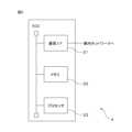
図5は、マスク画像生成の概要を説明する図である。ドライバ画像500にはドライバ501が表されている。そのため、ドライバ画像500とドライバが表されていない背景画像510との間の背景差分により、ドライバ画像500上でドライバ501が表されているドライバ領域502が特定される。そのため、ドライバ画像500のドライバ領域502内の各画素の値を所定値に書き換えてドライバ領域502をマスクすることで、マスク画像520が生成される。 FIG. 5 is a diagram illustrating an overview of mask image generation. A
なお、マスク画像生成部31は、所定のタイミングの前後において時系列に得られた複数のドライバ画像を用いてドライバ領域を検出してもよい。例えば、マスク画像生成部31は、複数のドライバ画像のそれぞれと背景画像との間で背景差分を実行することで、ドライバ画像ごとの個別のドライバ領域を検出する。そしてマスク画像生成部31は、ドライバ画像ごとの個別のドライバ領域の和集合あるいは積集合となる領域を改めてドライバ領域とする。マスク画像生成部31は、一連のドライバ画像の何れかにおいて求めたドライバ領域をマスクすることでマスク画像を生成すればよい。これにより、マスク画像生成部31は、ドライバ画像においてドライバが存在する可能性が高い領域をより確実にマスクすることができる。 Note that the mask
マスク画像生成部31は、生成したマスク画像を差分画像生成部32へわたす。 The mask
差分画像生成部32は、マスク画像と1以上の基準画像のそれぞれとの差分画像を生成する。基準画像には、ドライバシート及びステアリングが所定のポジションに設定されているときの車両10の車室内が表されている。なお、基準画像が複数用意される場合には、基準画像ごとに、互いに異なるドライバシートのポジション及びステアリングのポジションの組み合わせが表される。特に、複数の基準画像には、ドライバシート及びステアリングの可動部のうちの何れか一つのみが異なるポジションとなるように設定された2以上の基準画像が含まれることが好ましい。例えば、ドライバシートの座面の位置及びステアリングの奥行き方向の位置及び上下方向の位置が固定され、ドライバシートの背もたれの傾きのみが異なる2以上の基準画像が用意されることが好ましい。あるいは、ドライバシートの座面の位置及び背もたれの傾きと、ステアリングの上下方向の位置が固定され、ステアリングの奥行き方向の位置のみが異なる2以上の基準画像が用意されることが好ましい。これにより、個々の差分画像において、特定の可動部について、マスク画像に表される位置と対応する基準画像に表される位置との相違が明確となる。 The difference
差分画像生成部32は、1以上の基準画像のそれぞれについて、その基準画像とマスク画像の対応画素間の画素値の差の絶対値を算出する。そして差分画像生成部32は、1以上の基準画像のそれぞれについて、個々の画素ごとに、対応画素間の画素差の絶対値がその画素の値となるように差分画像を生成する。なお、基準画像及びマスク画像がカラー画像である場合、差分画像生成部32は、色成分ごとに上記の処理を実行することで差分画像を生成すればよい。これにより、差分画像は、基準画像に表されるドライバシート及びステアリングのポジションと、マスク画像に表されるドライバシート及びステアリングのポジションとの差が強調されたものとなる。 The difference
あるいは、差分画像生成部32は、各基準画像及びマスク画像に対して、所定のエッジ検出フィルタを適用してエッジの強度を表す画像を生成してもよい。そして差分画像生成部32は、基準画像ごとに、その基準画像から生成されたエッジ基準画像とマスク画像から生成されたエッジマスク画像との間で対応画素間の画素値の差の絶対値を算出してもよい。この場合も、差分画像生成部32は、個々の画素ごとに、その対応画素間の画素値の差の絶対値がその画素の値となるように差分画像を生成する。なお、差分画像生成部32は、所定のエッジ検出フィルタとして、例えば、Sobelフィルタ、PrewittフィルタあるいはLaplacianフィルタを用いることができる。 Alternatively, the difference
差分画像生成部32は、基準画像ごとに生成した差分画像を、推定部33へわたす。 The difference
推定部33は、基準画像ごとに生成された差分画像のそれぞれを、ドライバシートのポジションを推定する第1の識別器及びステアリングのポジションを推定する第2の識別器に入力する。これにより、推定部33は、差分画像ごとに、ドライバシートのポジションの個別推定値及びステアリングのポジションの個別推定値をもとめる。なお、推定部33は、第1の識別器及び第2の識別器として、例えば、複数の畳み込み層を有するコンボリューショナルニューラルネットワーク(CNN)型のアーキテクチャを持つディープニューラルネットワーク(DNN)を利用することができる。あるいは、推定部33は、第1の識別器及び第2の識別器として、self attention network(SAN)型のアーキテクチャを有するDNNを利用してもよい。これらの識別器は、様々なポジションのドライバシートあるいはステアリングが表された多数の教師画像を用いて、誤差逆伝搬法といった所定の学習手法に従って予め学習される。 The
なお、ドライバ画像上でステアリングが表される可能性がある範囲及びドライバシートが表される可能性がある範囲は想定される。上記のように、ドライバモニタカメラ2がインストルメントパネルまたはその近傍に設けられる場合、ステアリングはドライバシートよりもドライバモニタカメラ2の近くに位置している。そのため、ドライバ画像上でステアリングが表される範囲は、ドライバシートが表される範囲よりも大きくなる。そこで、推定部33は、ステアリングのポジションを推定する第2の識別器には、差分画像全体を入力する。一方、推定部33は、ドライバシートのポジションを推定する第1の識別器には、差分画像のうち、ドライバシートが表されている可能性が有る範囲のみを入力してもよい。 Note that a range where the steering wheel may be displayed on the driver image and a range where the driver seat may be displayed are assumed. As described above, when the
変形例によれば、推定部33は、第1の識別器及び第2の識別器の何れにも、差分画像全体を入力してもよい。また、一つの識別器が、ドライバシートのポジションとステアリングのポジションの両方を推定するように予め学習されてもよい。この場合には、推定部33は、差分画像をその一つの識別器に入力することで、ドライバシートのポジションとステアリングのポジションの両方の個別推定値を求めることができる。 According to a modification, the
推定部33は、各差分画像から推定されたドライバシートのポジションの個別推定値の統計的代表値、例えば、平均値あるいは中央値を、ドライバシートのポジションの推定値として算出する。同様に、推定部33は、各差分画像から推定されたステアリングのポジションの個別推定値の統計的代表値を、ステアリングのポジションの推定値として算出する。なお、基準画像が1枚だけしか用意されていない場合には、その1枚の基準画像とマスク画像間の差分により得られた差分画像について第1の識別器により算出されたドライバシートのポジションの個別推定値そのものが統計的代表値となる。すなわち、その個別推定値そのものが、ドライバシートのポジションの推定値となる。同様に、その1枚の基準画像とマスク画像間の差分により得られた差分画像について第2の識別器により算出されたステアリングのポジションの個別推定値そのものが、ステアリングのポジションの推定値となる。 The
なお、基準画像ごとに、ドライバシートのポジションの許容範囲が予め設定されてもよい。推定部33は、各差分画像から推定されたドライバシートのポジションの個別推定値のうち、その差分画像の生成に用いられた基準画像について設定された許容範囲に含まれるポジションの個別推定値を選択する。そして推定部33は、選択した個別推定値の統計的代表値を、ドライバシートのポジションの推定値として算出してもよい。同様に、基準画像ごとに、ステアリングのポジションの許容範囲が予め設定されてもよい。推定部33は、各差分画像から推定されたステアリングのポジションの個別推定値のうち、その差分画像の生成に用いられた基準画像について設定された許容範囲に含まれるポジションの個別推定値を選択する。そして推定部33は、選択した個別推定値の統計的代表値を、ステアリングのポジションの推定値とすればよい。 Note that the permissible range of the position of the driver seat may be set in advance for each reference image. The
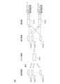
図6は、差分画像生成及びポジション推定値算出の概要を説明する図である。この例では、ドライバシートのポジションとステアリングのポジションの組み合わせが互いに異なるn個の基準画像600-1~600-n(nは2以上の整数)が予め用意されている。そして基準画像600-1~600-nのそれぞれに対して、マスク画像601との差分画像が生成される。すなわち、基準画像600-i(i=1,2,...,n)とマスク画像601とから差分画像602-iが生成される。生成された差分画像602-1~602-nは、1枚ずつ、第1の識別器610と第2の識別器620に入力される。なお、上記のように、第1の識別器610には、差分画像602-i上でドライバシートが表される可能性が有る領域603のみが入力され、第2の識別器620には、差分画像602-i全体が入力されてもよい。その結果として、差分画像602-1~602-nごとに、ドライバシートのポジションの個別推定値とステアリングのポジションの個別推定値とが算出される。 FIG. 6 is a diagram illustrating an overview of differential image generation and position estimated value calculation. In this example, n reference images 600-1 to 600-n (n is an integer of 2 or more) having different combinations of driver seat positions and steering positions are prepared in advance. Then, a difference image with the
図7は、基準画像ごとに設定されるドライバシートのポジションの許容範囲と、第1の識別器により算出されたポジションの個別推定値と、最終的に推定されるドライバシートのポジションとの関係を説明する図である。この例では、ドライバシートの背もたれの傾き角度が互いに異なるドライバシートが各基準画像0~11に表されているものとする。また、第1の識別器により出力されるドライバシートの背もたれの傾き角度の推定値は、10度~40度の範囲において5度単位で出力されるものとする。そして基準画像0~2に対して傾き角度の許容範囲は10度~25度の範囲に設定されている。また、基準画像3~5に対して傾き角度の許容範囲は20度~35度の範囲に設定されている。さらに、基準画像6~8に対して傾き角度の許容範囲は25度~40度の範囲に設定されている。そして基準画像9~11に対して傾き角度の許容範囲は15度~30度の範囲に設定されている。 FIG. 7 shows the relationship between the permissible range of the driver seat position set for each reference image, the individual estimated value of the position calculated by the first discriminator, and the finally estimated driver seat position. FIG. In this example, it is assumed that each of the
図7において、各星印701は、基準画像0~11のそれぞれについて算出された差分画像から第1の識別器により算出されたドライバシートの傾き角度の個別推定値を表す。この例では、基準画像5及び基準画像8については、ドライバシートの傾き角度の個別推定値が許容範囲から外れている。そのため、最終的なドライバシートの背もたれの傾き角度の推定において、基準画像5及び基準画像8に対応する差分画像から算出された個別推定値は除外される。そして基準画像0~4、6~7、9~11に対応する差分画像から算出された個別推定値の統計的代表値として、最終的なドライバシートの背もたれの傾き角度の推定値が算出される。 In FIG. 7, each
推定部33は、ドライバシートのポジションの推定値及びステアリングのポジションの推定値をメモリ22に保存する。 The
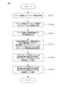
図8は、プロセッサ23により実行される、シートポジション推定処理の動作フローチャートである。プロセッサ23は、上述した所定のタイミングにおいて、以下の動作フローチャートに従ってシートポジション推定処理を実行すればよい。 FIG. 8 is an operational flowchart of the seat position estimation process executed by the
プロセッサ23のマスク画像生成部31は、ドライバ画像と背景画像との背景差分によりドライバ画像からドライバ領域を検出する(ステップS101)。そしてマスク画像生成部31は、ドライバ画像上のドライバ領域をマスクして、すなわち、ドライバ領域内の各画素の値を所定の値に書き換えてマスク画像を生成する(ステップS102)。 The mask
プロセッサ23の差分画像生成部32は、マスク画像と1以上の基準画像のそれぞれとの差分画像を生成する(ステップS103)。 The difference
プロセッサ23の推定部33は、基準画像ごとに生成された差分画像のそれぞれを、第1の識別器及び第2の識別器に入力する。これにより、推定部33は、差分画像ごとに、ドライバシートのポジションの個別推定値及びステアリングのポジションの個別推定値を算出する(ステップS104)。そして推定部33は、各差分画像から推定されたドライバシートのポジションの個別推定値の統計的代表値を、ドライバシートのポジションの推定値として算出する(ステップS105)。同様に、推定部33は、各差分画像から推定されたステアリングのポジションの個別推定値の統計的代表値を、ステアリングのポジションの推定値として算出する(ステップS106)。ステップS106の後、プロセッサ23は、シートポジション推定処理を終了する。 The
検出部34は、ECU4がドライバモニタカメラ2から受信したドライバ画像から、ドライバの顔が表された領域(以下、顔領域と呼ぶ)を検出する。 The
検出部34は、例えば、ドライバ画像を、画像からドライバの顔を検出するように予め学習された識別器に入力することで、そのドライバ画像から顔領域の候補を検出する。検出部34は、そのような識別器として、例えば、CNN型あるいはSAN型のアーキテクチャを持つDNNを利用することができる。あるいはまた、検出部34は、そのような識別器として、サポートベクトルマシンまたはAdaBoost識別器といった、DNN以外の機械学習手法に基づく識別器を利用してもよい。このような識別器は、ドライバの顔が表された多数の教師画像を用いて、誤差逆伝搬法といった所定の学習手法に従って予め学習される。 For example, the
検出部34は、識別器により出力された顔領域の候補が検出条件を満たすか否か判定し、顔領域の候補が検出条件を満たす場合、その候補を顔領域とする。検出条件は、ドライバ画像上でドライバの顔が存在すると想定される推定領域及びドライバ画像上での顔領域のサイズの許容範囲として設定される。すなわち、検出部34は、識別器により出力された顔領域の候補が、検出条件で示される推定領域に含まれ、かつ、顔領域のサイズが検出条件で示されるサイズの許容範囲内である場合、顔領域の候補は、検出条件を満たすと判定する。検出条件は、ドライバシートのポジションとステアリングのポジションの組み合わせに応じて設定される。本実施形態では、ドライバシートのポジションとステアリングのポジションの組み合わせごとの検出条件を表す検出条件テーブルが、メモリ22に予め記憶される。具体的に、ドライバシートの座面が前方に移動するほど、あるいは、背もたれの傾き角が小さくなるほど、ドライバの位置はドライバモニタカメラ2に近付く。そしてドライバの位置がドライバモニタカメラ2に近付くほど、ドライバ画像上でドライバの顔が表される領域は大きくなる。さらに、ドライバの位置がドライバモニタカメラ2に近付くほど、ドライバの動きに伴う、ドライバ画像上でのドライバの動き量も大きくなる。したがって、ドライバシートの座面が前方に移動するほど、あるいは、背もたれの傾き角が小さくなるほど、検出条件で示される推定領域は広く設定される。また、ステアリングのポジションに応じて、ドライバ画像上でステアリングが表される領域が変化する。そのため、検出条件で示される推定領域は、ステアリングのポジションに応じた、ドライバ画像上でステアリングが表される領域を含まないように設定される。検出部34は、検出条件テーブルを参照して、推定部33により求められた、ドライバシートのポジションの推定値とステアリングのポジションの推定値の組み合わせに対応する検出条件を特定する。そして検出部34は、特定した検出条件を顔領域の検出に利用する。 The
検出部34は、検出した顔領域の位置及び範囲を表す情報(例えば、顔領域の左上端の座標及び右下端の座標)を姿勢検出部35へ通知する。 The
姿勢検出部35は、ドライバ画像から検出された顔領域に基づいて、ドライバの姿勢を検出する。本実施形態では、姿勢検出部35は、ドライバの姿勢を表す情報として、ドライバの顔の位置及びドライバの顔の向きを検出する。 The
姿勢検出部35は、ドライバ画像の顔領域から、目尻、目頭、鼻尖点、口角点等のドライバの顔の複数の特徴点を検出する。その際、姿勢検出部35は、画像に表された顔の特徴点を検出するように予め学習された識別器に顔領域を入力することで、顔の特徴点を検出する。そのような識別器として、姿勢検出部35は、例えば、CNN型のアーキテクチャを持つDNN、サポートベクトルマシンまたはAdaBoost識別器を用いることができる。なお、顔領域検出用の識別器と顔の特徴点検出用の識別器は一体的に構成されてもよい。この場合には、検出部34が、ドライバ画像を識別器に入力することで、顔領域と顔の個々の特徴点のそれぞれを検出すればよい。あるいは、姿勢検出部35は、顔の特徴点を表すテンプレートと顔領域とのテンプレートマッチング、あるいは、顔の特徴点を検出する他の手法に従って、顔領域からドライバの顔の個々の特徴点を検出してもよい。 The
姿勢検出部35は、検出した顔の個々の特徴点を、顔の3次元形状を表す3次元顔モデルにフィッティングする。そして姿勢検出部35は、各特徴点が3次元顔モデルに最もフィッティングする際の3次元顔モデルの顔の向きを、ドライバの顔の向きとして検出する。なお、姿勢検出部35は、画像に表された顔の向きを判定する他の手法に従って、ドライバ画像に基づいてドライバの顔の向きを検出してもよい。 The
さらに、姿勢検出部35は、ドライバ画像における顔領域の重心位置を、ドライバの顔の位置として検出する。 Further, the
なお、姿勢検出部35は、ドライバの視線方向に基づいてドライバの姿勢を検出してもよい。この場合、姿勢検出部35は、顔領域からドライバの眼が表された眼領域を検出する。その際、姿勢検出部35は、上述した、顔の特徴点を検出する手法と同様の手法によって左右それぞれの眼について眼領域を検出すればよい。姿勢検出部35は、さらに、左右何れかの眼領域に対するテンプレートマッチングにより、瞳孔重心及びドライバモニタカメラ2の光源の角膜反射像(プルキンエ像)を検出する。そして姿勢検出部35は、瞳孔重心とプルキンエ像との位置関係に基づいて、ドライバの視線方向を検出すればよい。なお、姿勢検出部35は、ドライバの左右何れの眼領域も検出できない場合、視線方向の検出に失敗したと判定する。 Note that the
姿勢検出部35は、ドライバ画像に対するドライバの姿勢の検出結果、すなわち、ドライバの顔の位置及び顔の向きの検出結果を異常判定部36へ通知する。さらに、ドライバの視線方向の検出が行われている場合、姿勢検出部35は、視線方向の検出結果を異常判定部36へ通知する。 The
異常判定部36は、姿勢検出部35により検出されたドライバの姿勢が異常判定条件を満たす場合にドライバに異常が生じたと判定する。上記のように、本実施形態では、ドライバの姿勢はドライバの顔の位置及びドライバの顔の向きにより表される。また、異常判定条件は、ドライバの顔の位置または顔の向きが正常範囲から外れた状態が時間閾値以上継続することである。そこで、異常判定部36は、姿勢検出部35からドライバの顔の位置及び顔の向きが通知される度に、その顔の位置及び顔の向きが、予め設定された正常範囲に含まれるか否か判定する。そして異常判定部36は、ドライバの顔の位置または顔の向きが正常範囲から外れた状態が継続する期間の長さが時間閾値以上になると、ドライバに異常が生じたと判定する。また、ドライバの視線方向が検出されている場合、異常判定部36は、姿勢検出部35からドライバの視線方向が通知される度に、その視線方向が、予め設定された正常範囲に含まれるか否か判定する。そして異常判定部36は、ドライバの視線方向が正常範囲から外れた状態が継続する期間の長さが時間閾値以上になると、ドライバに異常が生じたと判定してもよい。 The
異常判定部36は、ドライバに異常が生じたか否かの判定結果を警告処理部37及び車両制御部38に通知する。 The
警告処理部37は、異常判定部36から、ドライバに異常が生じたとの判定結果を受け取ると、所定の警告処理を実施する。例えば、警告処理部37は、通知機器3が有するスピーカに、ドライバに運転姿勢を取ることを要求する音声信号あるいは警告音を発声させる。あるいは、警告処理部37は、通知機器3が有するディスプレイに、ドライバに運転姿勢を取ることを要求する警告メッセージを表示させる。あるいはまた、警告処理部37は、通知機器3が有する振動子を振動させる。 When the
警告処理部37は、通知機器3を介してドライバへ運転姿勢を取ることを要求する警告処理を実施した後に、異常判定部36からドライバに異常が生じていないとの判定結果を受け取ると、警告処理の実行を停止する。 When the
車両制御部38は、異常判定部36から、ドライバに異常が生じたとの判定結果を受け取るまでは、車両10に適用される運転制御レベルに従って車両10を制御する。車両10に適用される運転制御レベルが、ドライバが車両10の運転に関与しない運転制御レベルである場合、車両制御部38は、車両10が走行中の自車線に沿って走行するよう、車両10を制御する。そのために、車両制御部38は、車外カメラにより生成された画像から自車線と隣接車線とを区画する車線区画線、及び、車両10の周囲を走行する他の車両といった移動物体を検出する。そして車両制御部38は、検出された車線区画線と地図情報とを照合することで、車両10の位置及び姿勢を推定する。そして車両制御部38は、車両10の位置及び姿勢の推定結果と、車両10の周囲の個々の移動物体の検出結果とに基づいて、車両10が個々の移動物体と衝突せず、かつ、自車線に沿って走行するように車両10を制御する。 The
また、異常判定部36からドライバに異常が生じたとの判定結果を継続して一定期間にわたって受け取ると、車両制御部38は、車両10を緊急停車させるように車両10を制御する。なお、車両制御部38は、異常判定部36からドライバに異常が生じたとの判定結果を受け取ると直ちに車両10を緊急停車させるように車両10を制御してもよい。その際、車両制御部38は、車両10の位置及び姿勢の推定結果、車両10の周囲の個々の移動物体の検出結果、及び、地図情報に基づいて、車両10を路肩に移動させてから停車させてもよい。 Further, when receiving a determination result indicating that an abnormality has occurred in the driver continuously from the
図9は、プロセッサ23により実行される車両制御処理の動作フローチャートである。プロセッサ23は、所定の周期ごとに、以下の動作フローチャートに従って車両制御処理を実行すればよい。 FIG. 9 is an operational flowchart of the vehicle control process executed by the
プロセッサ23の検出部34は、最新のドライバ画像から顔領域の候補を検出する(ステップS201)。また、検出部34は、ドライバシートのポジションの推定値及びステアリングのポジションの推定値の組み合わせに基づいて検出条件を設定する(ステップS202)。そして検出部34は、検出した顔領域の候補が検出条件を満たすか否か判定する(ステップS203)。 The
顔領域の候補が検出条件を満たさない場合(ステップS203-No)、検出部34は、ドライバの顔の検出に失敗したと判定する。そしてプロセッサ23は、車両制御処理を終了する。一方、顔領域の候補が検出条件を満たす場合(ステップS203-Yes)、検出部34は、ドライバの顔の検出に成功したと判定する。そしてプロセッサ23の姿勢検出部35は、ドライバ画像から検出された顔領域に基づいてドライバの顔の位置及びドライバの顔の向きを検出する(ステップS204)。なお、上記のように、姿勢検出部35は、顔領域からドライバの視線方向を検出してもよい。 If the face area candidate does not satisfy the detection conditions (step S203-No), the
プロセッサ23の異常判定部36は、ドライバの顔の位置及びドライバの顔の向きに基づいて、ドライバに異常が生じたか否か判定する(ステップS205)。その際、異常判定部36は、直近の所定時間における時系列の一連のドライバ画像におけるドライバの顔の向き及び顔の位置あるいは視線方向に基づいて、ドライバに異常が生じたか否か判定すればよい。異常判定部36がドライバに異常が生じたと判定した場合(ステップS205-Yes)、プロセッサ23の警告処理部37は、通知機器3を介してドライバに運転姿勢を取ることを要求する警告を通知する(ステップS206)。さらに、プロセッサ23の車両制御部38は、車両10を緊急停車させるよう、車両10を制御する(ステップS207)。 The
一方、ステップS205において、異常判定部36がドライバに異常が生じていないと判定した場合(ステップS205-No)、車両制御部38は、車両10に適用される運転制御レベルに従って車両10を制御する(ステップS208)。 On the other hand, in step S205, if the
ステップS207またはステップS208の後、プロセッサ23は、車両制御処理を終了する。 After step S207 or step S208, the
以上に説明してきたように、このシートポジション推定装置は、ドライバが乗車中の車両の車室内が表された画像からドライバが表されている領域をマスクしたマスク画像を生成する。さらに、このシートポジション推定装置は、マスク画像と、ドライバシートの所定のポジション及びステアリングの所定のポジションでの車室内が表された少なくとも一枚の基準画像のそれぞれとの差分画像を生成する。そしてこのシートポジション推定装置は、生成した各差分画像を識別器に入力することで、ドライバシートのポジション及びステアリングポジションの推定値を得る。これにより、このシートポジション推定装置は、車両の車室内が表された画像から、ドライバシートのポジションを推定することができる。 As described above, this seat position estimating device generates a mask image in which a region in which the driver is shown is masked from an image showing the interior of the vehicle in which the driver is riding. Further, this seat position estimating device generates a difference image between the mask image and at least one reference image representing the interior of the vehicle at a predetermined position of the driver seat and a predetermined position of the steering wheel. This seat position estimating device obtains estimated values of the driver seat position and steering position by inputting each generated difference image to a classifier. Thereby, this seat position estimating device can estimate the position of the driver seat from an image showing the interior of the vehicle.
変形例によれば、マスク画像生成部31は、背景差分以外の方法によってドライバ領域を特定してもよい。例えば、マスク画像生成部31は、時系列に得られる一連のドライバ画像のそれぞれに対して、検出部34の処理と同様の処理を実行することでドライバが表されている候補領域を検出する。さらに、マスク画像生成部31は、一連のドライバ画像のそれぞれから検出された候補領域の積集合となる領域を求める。この積集合となる領域は、各ドライバ画像においてドライバが表されていると判断されているので、ドライバが実際に表されている可能性が高い。そこで、マスク画像生成部31は、この積集合となる領域をドライバ領域として特定してもよい。 According to a modification, the mask
また、車両によっては、ドライバ画像からの顔領域の検出の精度にステアリングのポジションが影響しないような位置にドライバモニタカメラ2が取り付けられていることがある。このような場合には、シートポジション推定装置は、ステアリングのポジションを推定せず、ドライバシートのポジションのみを推定してもよい。この場合、各基準画像は、ステアリングのポジションにかかわらず、互いに異なるポジションのドライバシートが表されていればよい。また、推定部33において、第2の識別器によるステアリングのポジションの個別推定値の算出及び各個別推定値に基づくステアリングのポジションの推定値の算出に関する処理は省略される。この変形例によれば、ステアリングのポジションの推定に関する処理が省略されるので、プロセッサ23の演算負荷が軽減される。 Further, depending on the vehicle, the
また、上記の実施形態または変形例による、ECU4のプロセッサ23の機能を実現するコンピュータプログラムは、半導体メモリ、磁気記録媒体または光記録媒体といった、コンピュータ読取可能な可搬性の記録媒体に記録された形で提供されてもよい。 Further, the computer program that realizes the functions of the
以上のように、当業者は、本発明の範囲内で、実施される形態に合わせて様々な変更を行うことができる。 As described above, those skilled in the art can make various changes within the scope of the present invention according to the embodiment.
1 車両制御システム
2 ドライバモニタカメラ
3 通知機器
4 電子制御装置(シートポジション推定装置)
10 車両
11 ドライバシート
12 ステアリング
21 通信インターフェース
22 メモリ
23 プロセッサ
31 マスク画像生成部
32 差分画像生成部
33 推定部
34 検出部
35 姿勢検出部
36 異常判定部
37 警告処理部
38 車両制御部1
10
Claims (6)
Translated fromJapanese前記車室内を撮影するように設けられた撮像部により前記車両にドライバが乗車している間に生成されたドライバ画像において前記ドライバが表されている領域を特定し、特定した領域をマスクすることでマスク画像を生成するマスク画像生成部と、
前記マスク画像と前記1以上の基準画像のそれぞれとの差分により1以上の差分画像を生成する差分画像生成部と、
前記1以上の差分画像のそれぞれを、前記ドライバシートのポジションを推定するように予め学習された識別器に入力することで、前記1以上の差分画像のそれぞれについて前記ドライバシートのポジションの個別推定値を求め、前記1以上の差分画像のそれぞれについての前記個別推定値の統計的代表値を、前記ドライバシートのポジションの推定値として算出する推定部と、
を有するシートポジション推定装置。a storage unit that stores one or more reference images representing an interior of the vehicle when a driver seat of the vehicle is in a predetermined position, and in which positions of the driver seat in each of the one or more reference images are different from each other; ,
Identifying an area in which the driver is represented in a driver image generated while the driver is riding in the vehicle by an imaging unit provided to photograph the interior of the vehicle, and masking the identified area. a mask image generation unit that generates a mask image;
a difference image generation unit that generates one or more difference images based on the difference between the mask image and each of the one or more reference images;
By inputting each of the one or more difference images to a classifier trained in advance to estimate the position of the driver seat, an individual estimated value of the position of the driver seat is obtained for each of the one or more difference images. an estimating unit that calculates a statistically representative value of the individual estimated values for each of the one or more difference images as an estimated value of the position of the driver seat;
A seat position estimation device having:
前記推定部は、前記1以上の差分画像のそれぞれについて求められた前記ドライバシートのポジションの個別推定値のうち、当該差分画像に対応する前記基準画像の前記許容範囲に含まれる個別推定値の統計的代表値を、前記ドライバシートのポジションの推定値として算出する、請求項1に記載のシートポジション推定装置。A permissible range of the position of the driver seat is set for each of the one or more reference images,
The estimation unit calculates statistics of individual estimated values included in the allowable range of the reference image corresponding to the difference image, among the individual estimated values of the position of the driver seat obtained for each of the one or more difference images. The seat position estimating device according to claim 1, wherein the representative value is calculated as the estimated value of the position of the driver seat.
前記推定部は、前記1以上の差分画像のそれぞれを、前記ステアリングのポジションを推定するように予め学習された第2の識別器に入力することで、前記1以上の差分画像のそれぞれについて前記ステアリングのポジションの個別推定値を求め、前記1以上の差分画像のそれぞれについての前記ステアリングのポジションの個別推定値の統計的代表値を、前記ステアリングのポジションの推定値としてさらに算出する、請求項1~3の何れか一項に記載のシートポジション推定装置。Each of the one or more reference images further represents steering of the vehicle in different positions,
The estimation unit inputs each of the one or more difference images to a second classifier trained in advance to estimate the position of the steering wheel, thereby determining the steering wheel position for each of the one or more difference images. Further, a statistical representative value of the individual estimated values of the steering position for each of the one or more difference images is further calculated as the estimated value of the steering position. 3. The seat position estimation device according to any one of 3.
前記マスク画像と、前記車両のドライバシートが所定のポジションとなっているときの前記車室内を表す1以上の基準画像のそれぞれとの差分により1以上の差分画像を生成し、前記1以上の基準画像のそれぞれにおける前記ドライバシートのポジションが互いに異なり、
前記1以上の差分画像のそれぞれを、前記ドライバシートのポジションを推定するように予め学習された識別器に入力することで、前記1以上の差分画像のそれぞれについて前記ドライバシートのポジションの個別推定値を求め、前記1以上の差分画像のそれぞれについての前記個別推定値の統計的代表値を、前記ドライバシートのポジションの推定値として算出する、
ことを含むシートポジション推定方法。Identifying an area in which the driver is represented in a driver image generated while the driver is in the vehicle by an imaging unit installed to photograph the interior of the vehicle, and masking the identified area. Generate a mask image by
One or more difference images are generated by the difference between the mask image and each of the one or more reference images representing the inside of the vehicle when the driver seat of the vehicle is in a predetermined position, and the one or more reference images The position of the driver seat in each of the images is different from each other,
By inputting each of the one or more difference images to a classifier trained in advance to estimate the position of the driver seat, an individual estimated value of the position of the driver seat is obtained for each of the one or more difference images. and calculating a statistical representative value of the individual estimated values for each of the one or more difference images as an estimated value of the position of the driver seat.
A seat position estimation method including
前記マスク画像と、前記車両のドライバシートが所定のポジションとなっているときの前記車室内を表す1以上の基準画像のそれぞれとの差分により1以上の差分画像を生成し、前記1以上の基準画像のそれぞれにおける前記ドライバシートのポジションが互いに異なり、
前記1以上の差分画像のそれぞれを、前記ドライバシートのポジションを推定するように予め学習された識別器に入力することで、前記1以上の差分画像のそれぞれについて前記ドライバシートのポジションの個別推定値を求め、前記1以上の差分画像のそれぞれについての前記個別推定値の統計的代表値を、前記ドライバシートのポジションの推定値として算出する、
ことを前記車両に搭載されたプロセッサに実行させるためのシートポジション推定用コンピュータプログラム。Identifying an area in which the driver is represented in a driver image generated while the driver is in the vehicle by an imaging unit installed to photograph the interior of the vehicle, and masking the identified area. Generate a mask image by
One or more difference images are generated by the difference between the mask image and each of the one or more reference images representing the inside of the vehicle when the driver seat of the vehicle is in a predetermined position, and the one or more reference images The position of the driver seat in each of the images is different from each other,
By inputting each of the one or more difference images to a classifier trained in advance to estimate the position of the driver seat, an individual estimated value of the position of the driver seat is obtained for each of the one or more difference images. and calculating a statistical representative value of the individual estimated values for each of the one or more difference images as an estimated value of the position of the driver seat.
A computer program for estimating a seat position that causes a processor installed in the vehicle to perform the following steps.
Priority Applications (3)
| Application Number | Priority Date | Filing Date | Title |
|---|---|---|---|
| JP2022089735AJP7683546B2 (en) | 2022-06-01 | 2022-06-01 | Seat position estimation device, seat position estimation method, and computer program for seat position estimation |
| US18/198,432US20230394702A1 (en) | 2022-06-01 | 2023-05-17 | Device, method, and computer program for estimating seat position |
| CN202310595290.8ACN117152721A (en) | 2022-06-01 | 2023-05-24 | Seat positioning estimation device, seat positioning estimation method, and seat positioning estimation computer program |
Applications Claiming Priority (1)
| Application Number | Priority Date | Filing Date | Title |
|---|---|---|---|
| JP2022089735AJP7683546B2 (en) | 2022-06-01 | 2022-06-01 | Seat position estimation device, seat position estimation method, and computer program for seat position estimation |
Publications (2)
| Publication Number | Publication Date |
|---|---|
| JP2023177045Atrue JP2023177045A (en) | 2023-12-13 |
| JP7683546B2 JP7683546B2 (en) | 2025-05-27 |
Family
ID=88884958
Family Applications (1)
| Application Number | Title | Priority Date | Filing Date |
|---|---|---|---|
| JP2022089735AActiveJP7683546B2 (en) | 2022-06-01 | 2022-06-01 | Seat position estimation device, seat position estimation method, and computer program for seat position estimation |
Country Status (3)
| Country | Link |
|---|---|
| US (1) | US20230394702A1 (en) |
| JP (1) | JP7683546B2 (en) |
| CN (1) | CN117152721A (en) |
Citations (2)
| Publication number | Priority date | Publication date | Assignee | Title |
|---|---|---|---|---|
| JP2008001136A (en)* | 2006-06-20 | 2008-01-10 | Takata Corp | Vehicle occupant seat detection system, operating device control system, and vehicle |
| US20210334564A1 (en)* | 2018-11-21 | 2021-10-28 | Lg Electronics Inc. | Method for monitoring an occupant and a device therefor |
- 2022
- 2022-06-01JPJP2022089735Apatent/JP7683546B2/enactiveActive
- 2023
- 2023-05-17USUS18/198,432patent/US20230394702A1/enactivePending
- 2023-05-24CNCN202310595290.8Apatent/CN117152721A/enactivePending
Patent Citations (2)
| Publication number | Priority date | Publication date | Assignee | Title |
|---|---|---|---|---|
| JP2008001136A (en)* | 2006-06-20 | 2008-01-10 | Takata Corp | Vehicle occupant seat detection system, operating device control system, and vehicle |
| US20210334564A1 (en)* | 2018-11-21 | 2021-10-28 | Lg Electronics Inc. | Method for monitoring an occupant and a device therefor |
Also Published As
| Publication number | Publication date |
|---|---|
| CN117152721A (en) | 2023-12-01 |
| US20230394702A1 (en) | 2023-12-07 |
| JP7683546B2 (en) | 2025-05-27 |
Similar Documents
| Publication | Publication Date | Title |
|---|---|---|
| US8564657B2 (en) | Object motion detection system based on combining 3D warping techniques and a proper object motion detection | |
| US7619668B2 (en) | Abnormality detecting apparatus for imaging apparatus | |
| JP6350145B2 (en) | Face orientation detection device and vehicle warning system | |
| US10561356B2 (en) | Driver's physical condition detection device and method | |
| US11919522B2 (en) | Apparatus and method for determining state | |
| WO2019092996A1 (en) | Orientation detection device and orientation detection program | |
| JP2019091255A (en) | Information processing apparatus, driver monitoring system, information processing method, and information processing program | |
| JP2018048949A (en) | Object identification device | |
| US20230227044A1 (en) | Apparatus, method, and computer program for monitoring driver | |
| JP7537450B2 (en) | Vehicle control device, vehicle control method, and vehicle control computer program | |
| US11694449B2 (en) | Driver monitor and method for monitoring driver | |
| US20210052156A1 (en) | Gaze detector, method for controlling gaze detector, method for detecting corneal reflection image position, and storage medium | |
| US20240336192A1 (en) | Monitoring device, storage medium storing computer program for monitoring, and monitoring method | |
| US20220066551A1 (en) | Apparatus and method for obtaining facial information | |
| US20240059321A1 (en) | Travel controller and travel control method | |
| US20240029454A1 (en) | Line of sight estimating device, storage medium for storing computer program for line of sight estimation, and line of sight estimating method | |
| JP7683546B2 (en) | Seat position estimation device, seat position estimation method, and computer program for seat position estimation | |
| JP2022007157A (en) | Vehicle control device | |
| JP7700814B2 (en) | Driver monitor device, driver monitor method, and computer program for driver monitor | |
| US12157487B2 (en) | Monitoring device, storage medium storing computer program for monitoring, and monitoring method | |
| JP2004334784A (en) | Confirmation operation detection device and alarm system | |
| US20240262380A1 (en) | Driver monitor, method, and computer program for monitoring driver | |
| JP2023177049A (en) | arm detection device | |
| JP2023047835A (en) | On-vehicle device and passenger monitoring method | |
| JP2024059261A (en) | Road sign detection device |
Legal Events
| Date | Code | Title | Description |
|---|---|---|---|
| A621 | Written request for application examination | Free format text:JAPANESE INTERMEDIATE CODE: A621 Effective date:20240209 | |
| A977 | Report on retrieval | Free format text:JAPANESE INTERMEDIATE CODE: A971007 Effective date:20241122 | |
| A131 | Notification of reasons for refusal | Free format text:JAPANESE INTERMEDIATE CODE: A131 Effective date:20241203 | |
| A521 | Request for written amendment filed | Free format text:JAPANESE INTERMEDIATE CODE: A523 Effective date:20250107 | |
| TRDD | Decision of grant or rejection written | ||
| A01 | Written decision to grant a patent or to grant a registration (utility model) | Free format text:JAPANESE INTERMEDIATE CODE: A01 Effective date:20250415 | |
| A61 | First payment of annual fees (during grant procedure) | Free format text:JAPANESE INTERMEDIATE CODE: A61 Effective date:20250428 | |
| R150 | Certificate of patent or registration of utility model | Ref document number:7683546 Country of ref document:JP Free format text:JAPANESE INTERMEDIATE CODE: R150 |