JP2023174874A - Coding device, decoding device, coding method, and decoding method - Google Patents
Coding device, decoding device, coding method, and decoding methodDownload PDFInfo
- Publication number
- JP2023174874A JP2023174874AJP2023179468AJP2023179468AJP2023174874AJP 2023174874 AJP2023174874 AJP 2023174874AJP 2023179468 AJP2023179468 AJP 2023179468AJP 2023179468 AJP2023179468 AJP 2023179468AJP 2023174874 AJP2023174874 AJP 2023174874A
- Authority
- JP
- Japan
- Prior art keywords
- transformation
- base
- transform
- size
- block
- Prior art date
- Legal status (The legal status is an assumption and is not a legal conclusion. Google has not performed a legal analysis and makes no representation as to the accuracy of the status listed.)
- Granted
Links
Images


Classifications
- H—ELECTRICITY
- H04—ELECTRIC COMMUNICATION TECHNIQUE
- H04N—PICTORIAL COMMUNICATION, e.g. TELEVISION
- H04N19/00—Methods or arrangements for coding, decoding, compressing or decompressing digital video signals
- H04N19/10—Methods or arrangements for coding, decoding, compressing or decompressing digital video signals using adaptive coding
- H04N19/102—Methods or arrangements for coding, decoding, compressing or decompressing digital video signals using adaptive coding characterised by the element, parameter or selection affected or controlled by the adaptive coding
- H04N19/12—Selection from among a plurality of transforms or standards, e.g. selection between discrete cosine transform [DCT] and sub-band transform or selection between H.263 and H.264
- H—ELECTRICITY
- H04—ELECTRIC COMMUNICATION TECHNIQUE
- H04N—PICTORIAL COMMUNICATION, e.g. TELEVISION
- H04N19/00—Methods or arrangements for coding, decoding, compressing or decompressing digital video signals
- H04N19/10—Methods or arrangements for coding, decoding, compressing or decompressing digital video signals using adaptive coding
- H04N19/102—Methods or arrangements for coding, decoding, compressing or decompressing digital video signals using adaptive coding characterised by the element, parameter or selection affected or controlled by the adaptive coding
- H04N19/124—Quantisation
- H—ELECTRICITY
- H04—ELECTRIC COMMUNICATION TECHNIQUE
- H04N—PICTORIAL COMMUNICATION, e.g. TELEVISION
- H04N19/00—Methods or arrangements for coding, decoding, compressing or decompressing digital video signals
- H04N19/10—Methods or arrangements for coding, decoding, compressing or decompressing digital video signals using adaptive coding
- H04N19/134—Methods or arrangements for coding, decoding, compressing or decompressing digital video signals using adaptive coding characterised by the element, parameter or criterion affecting or controlling the adaptive coding
- H04N19/157—Assigned coding mode, i.e. the coding mode being predefined or preselected to be further used for selection of another element or parameter
- H—ELECTRICITY
- H04—ELECTRIC COMMUNICATION TECHNIQUE
- H04N—PICTORIAL COMMUNICATION, e.g. TELEVISION
- H04N19/00—Methods or arrangements for coding, decoding, compressing or decompressing digital video signals
- H04N19/10—Methods or arrangements for coding, decoding, compressing or decompressing digital video signals using adaptive coding
- H04N19/169—Methods or arrangements for coding, decoding, compressing or decompressing digital video signals using adaptive coding characterised by the coding unit, i.e. the structural portion or semantic portion of the video signal being the object or the subject of the adaptive coding
- H04N19/17—Methods or arrangements for coding, decoding, compressing or decompressing digital video signals using adaptive coding characterised by the coding unit, i.e. the structural portion or semantic portion of the video signal being the object or the subject of the adaptive coding the unit being an image region, e.g. an object
- H04N19/176—Methods or arrangements for coding, decoding, compressing or decompressing digital video signals using adaptive coding characterised by the coding unit, i.e. the structural portion or semantic portion of the video signal being the object or the subject of the adaptive coding the unit being an image region, e.g. an object the region being a block, e.g. a macroblock
- H—ELECTRICITY
- H04—ELECTRIC COMMUNICATION TECHNIQUE
- H04N—PICTORIAL COMMUNICATION, e.g. TELEVISION
- H04N19/00—Methods or arrangements for coding, decoding, compressing or decompressing digital video signals
- H04N19/60—Methods or arrangements for coding, decoding, compressing or decompressing digital video signals using transform coding
- H04N19/625—Methods or arrangements for coding, decoding, compressing or decompressing digital video signals using transform coding using discrete cosine transform [DCT]
Landscapes
- Engineering & Computer Science (AREA)
- Multimedia (AREA)
- Signal Processing (AREA)
- Physics & Mathematics (AREA)
- Discrete Mathematics (AREA)
- General Physics & Mathematics (AREA)
- Compression Or Coding Systems Of Tv Signals (AREA)
Abstract
Translated fromJapaneseDescription
Translated fromJapanese本開示は、符号化装置、復号装置、符号化方法及び復号方法に関する。 The present disclosure relates to an encoding device, a decoding device, an encoding method, and a decoding method.
HEVC(High-Efficiency Video Coding)と称される映像符号化標準規格が、JCT-VC(Joint Collaborative Team on Video Coding)により標準化されている。 A video coding standard called HEVC (High-Efficiency Video Coding) has been standardized by JCT-VC (Joint Collaborative Team on Video Coding).
このような符号化及び復号技術では、さらなる圧縮効率の向上及び処理負荷の軽減が求められている。 Such encoding and decoding techniques are required to further improve compression efficiency and reduce processing load.
そこで、本開示は、さらなる圧縮効率の向上及び処理負荷の軽減を実現できる符号化装置、復号装置、符号化方法又は復号方法を提供する。 Therefore, the present disclosure provides an encoding device, a decoding device, an encoding method, or a decoding method that can further improve compression efficiency and reduce processing load.
本開示の一態様に係る符号化装置は、回路とメモリとを備える符号化装置であって、前記回路は前記メモリを用いて、符号化対象ブロックに水平方向の変換及び垂直方向の変換を実行すると判定した場合に、水平方向の変換基底及び垂直方向の変換基底をそれぞれ用いて、前記符号化対象ブロックの残差に前記水平方向の変換及び前記垂直方向の変換を行うことで第1の変換係数を生成し、前記符号化対象ブロックに非分離(non-separable)変換を実行すると判定した場合に、前記第1の変換係数に前記非分離変換を行うことで第2の変換係数を生成し、(i)前記符号化対象ブロックに対して、前記符号化対象ブロックのサイズに基づいて変換基底の選択が行われると判定した場合、前記回路は、前記水平方向の変換及び前記垂直方向の変換を実行する前に、前記符号化対象ブロックの水平サイズが閾値サイズよりも大きい第1の水平サイズのときに、変換基底の候補の中から、第1の変換基底を前記水平方向の変換基底として選択し、前記符号化対象ブロックの前記水平サイズが前記閾値サイズ以下のときに、前記変換基底の候補の中から、前記第1の変換基底とは異なる第2の変換基底を前記水平方向の変換基底として選択し、前記符号化対象ブロックの垂直サイズが前記閾値サイズよりも大きい第1の垂直サイズのときに、前記変換基底の候補の中から、前記第1の変換基底を前記垂直方向の変換基底として選択し、前記符号化対象ブロックの前記垂直サイズが前記閾値サイズ以下のときに、前記変換基底の候補の中から、前記第2の変換基底を前記垂直方向の変換基底として選択し、(ii)前記符号化対象ブロックに前記非分離変換を実行する場合、基本変換基底を前記垂直方向の変換基底及び前記水平方向の変換基底として選択する。 An encoding device according to an aspect of the present disclosure is an encoding device including a circuit and a memory, and the circuit uses the memory to perform horizontal transformation and vertical transformation on a block to be encoded. If it is determined that this is the case, the first transformation is performed by performing the horizontal transformation and the vertical transformation on the residual of the encoding target block using a horizontal transformation base and a vertical transformation base, respectively. If it is determined that a non-separable transform is to be performed on the block to be encoded, a second transform coefficient is generated by performing the non-separable transform on the first transform coefficient. , (i) If it is determined that a transformation base is to be selected for the encoding target block based on the size of the encoding target block, the circuit performs the horizontal transformation and the vertical transformation. When the horizontal size of the block to be encoded is a first horizontal size larger than the threshold size, a first transformation base is selected as the horizontal transformation base from among the transformation base candidates. and when the horizontal size of the block to be encoded is equal to or smaller than the threshold size, a second transform base different from the first transform base is selected from among the transform base candidates for the horizontal transform. When the vertical size of the block to be encoded is a first vertical size larger than the threshold size, the first transform base is selected as a base from among the transform base candidates. when the vertical size of the block to be encoded is equal to or less than the threshold size, the second transform base is selected as the vertical transform base from among the transform base candidates; ii) When performing the non-separable transform on the block to be encoded, a basic transform base is selected as the vertical transform base and the horizontal transform base.
本開示の一態様に係る復号装置は、回路とメモリとを備える復号装置であって、前記回路は前記メモリを用いて、復号対象ブロックに非分離(non-separable)逆変換を実行すると判定した場合に、第2の変換係数に前記非分離逆変換を行うことで第1の変換係数を生成し、前記復号対象ブロックに水平方向の逆変換及び垂直方向の逆変換を実行すると判定した場合に、水平方向の逆変換基底及び垂直方向の逆変換基底をそれぞれ用いて、前記第1の変換係数に前記水平方向の逆変換及び前記垂直方向の逆変換を行うことで前記復号対象ブロックの残差を生成し、(i)前記復号対象ブロックに対して、前記復号対象ブロックのサイズに基づいて変換基底の選択が行われると判定した場合、前記回路は、前記水平方向の逆変換及び前記垂直方向の逆変換を実行する前に、前記復号対象ブロックの水平サイズが閾値サイズよりも大きい第1の水平サイズのときに、逆変換基底の候補の中から、第1の逆変換基底を前記水平方向の逆変換基底として選択し、前記復号対象ブロックの前記水平サイズが前記閾値サイズ以下のときに、前記逆変換基底の候補の中から、前記第1の逆変換基底とは異なる第2の逆変換基底を前記水平方向の逆変換基底として選択し、前記復号対象ブロックの垂直サイズが前記閾値サイズよりも大きい第1の垂直サイズのときに、前記逆変換基底の候補の中から、前記第1の逆変換基底を前記垂直方向の逆変換基底として選択し、前記復号対象ブロックの前記垂直サイズが前記閾値サイズ以下のときに、前記逆変換基底の候補の中から、前記第2の逆変換基底を前記垂直方向の逆変換基底として選択し、(ii)前記復号対象ブロックに前記非分離逆変換を実行する場合、基本変換基底を前記垂直方向の逆変換基底及び前記水平方向の逆変換基底として選択する。 A decoding device according to an aspect of the present disclosure is a decoding device including a circuit and a memory, wherein the circuit determines to use the memory to perform non-separable inverse transformation on a block to be decoded. In this case, when it is determined that the first transform coefficient is generated by performing the non-separable inverse transform on the second transform coefficient, and the horizontal direction inverse transform and the vertical direction inverse transform are to be performed on the block to be decoded. , the residual of the block to be decoded is obtained by performing the horizontal inverse transform and the vertical inverse transform on the first transform coefficient using a horizontal inverse transform base and a vertical inverse transform base, respectively. (i) If it is determined that a transformation base is selected for the decoding target block based on the size of the decoding target block, the circuit generates the horizontal direction inverse transform and the vertical direction When the horizontal size of the block to be decoded is a first horizontal size larger than the threshold size, a first inverse transform base is selected from among the inverse transform base candidates in the horizontal direction. and when the horizontal size of the block to be decoded is less than or equal to the threshold size, a second inverse transform different from the first inverse transform base is selected from among the candidates for the inverse transform base. A base is selected as the inverse transform base in the horizontal direction, and when the vertical size of the block to be decoded is a first vertical size larger than the threshold size, the first base is selected from among the candidates for the inverse transform base. An inverse transform base is selected as the vertical inverse transform base, and when the vertical size of the block to be decoded is less than or equal to the threshold size, the second inverse transform base is selected from among the candidates for the inverse transform base. (ii) when performing the non-separable inverse transform on the block to be decoded, selecting a basic transform base as the vertical inverse transform base and the horizontal inverse transform base; do.
なお、これらの全般的または具体的な態様は、システム、方法、集積回路、コンピュータプログラムまたはコンピュータ読み取り可能なCD-ROMなどの記録媒体で実現されてもよく、システム、方法、集積回路、コンピュータプログラム及び記録媒体の任意な組み合わせで実現されてもよい。 Note that these general or specific aspects may be realized by a system, a method, an integrated circuit, a computer program, or a computer-readable recording medium such as a CD-ROM. and a recording medium may be used in any combination.
本開示は、さらなる圧縮効率の向上及び処理負荷の軽減を実現できる符号化装置、復号装置、符号化方法又は復号方法を提供することができる。 The present disclosure can provide an encoding device, a decoding device, an encoding method, or a decoding method that can further improve compression efficiency and reduce processing load.
以下、実施の形態について図面を参照しながら具体的に説明する。 Hereinafter, embodiments will be specifically described with reference to the drawings.
なお、以下で説明する実施の形態は、いずれも包括的または具体的な例を示すものである。以下の実施の形態で示される数値、形状、材料、構成要素、構成要素の配置位置及び接続形態、ステップ、ステップの順序などは、一例であり、請求の範囲を限定する主旨ではない。また、以下の実施の形態における構成要素のうち、最上位概念を示す独立請求項に記載されていない構成要素については、任意の構成要素として説明される。 Note that the embodiments described below are all inclusive or specific examples. The numerical values, shapes, materials, components, arrangement positions and connection forms of the components, steps, order of steps, etc. shown in the following embodiments are merely examples, and do not limit the scope of the claims. Further, among the constituent elements in the following embodiments, constituent elements that are not described in the independent claims indicating the most significant concept will be described as arbitrary constituent elements.
(実施の形態1)
まず、後述する本開示の各態様で説明する処理及び/または構成を適用可能な符号化装置及び復号装置の一例として、実施の形態1の概要を説明する。ただし、実施の形態1は、本開示の各態様で説明する処理及び/または構成を適用可能な符号化装置及び復号装置の一例にすぎず、本開示の各態様で説明する処理及び/または構成は、実施の形態1とは異なる符号化装置及び復号装置においても実施可能である。(Embodiment 1)
First, an overview of
実施の形態1に対して本開示の各態様で説明する処理及び/または構成を適用する場合、例えば以下のいずれかを行ってもよい。 When applying the processing and/or configuration described in each aspect of the present disclosure to
(1)実施の形態1の符号化装置または復号装置に対して、当該符号化装置または復号装置を構成する複数の構成要素のうち、本開示の各態様で説明する構成要素に対応する構成要素を、本開示の各態様で説明する構成要素に置き換えること
(2)実施の形態1の符号化装置または復号装置に対して、当該符号化装置または復号装置を構成する複数の構成要素のうち一部の構成要素について機能または実施する処理の追加、置き換え、削除などの任意の変更を施した上で、本開示の各態様で説明する構成要素に対応する構成要素を、本開示の各態様で説明する構成要素に置き換えること
(3)実施の形態1の符号化装置または復号装置が実施する方法に対して、処理の追加、及び/または当該方法に含まれる複数の処理のうちの一部の処理について置き換え、削除などの任意の変更を施した上で、本開示の各態様で説明する処理に対応する処理を、本開示の各態様で説明する処理に置き換えること
(4)実施の形態1の符号化装置または復号装置を構成する複数の構成要素のうちの一部の構成要素を、本開示の各態様で説明する構成要素、本開示の各態様で説明する構成要素が備える機能の一部を備える構成要素、または本開示の各態様で説明する構成要素が実施する処理の一部を実施する構成要素と組み合わせて実施すること
(5)実施の形態1の符号化装置または復号装置を構成する複数の構成要素のうちの一部の構成要素が備える機能の一部を備える構成要素、または実施の形態1の符号化装置または復号装置を構成する複数の構成要素のうちの一部の構成要素が実施する処理の一部を実施する構成要素を、本開示の各態様で説明する構成要素、本開示の各態様で説明する構成要素が備える機能の一部を備える構成要素、または本開示の各態様で説明する構成要素が実施する処理の一部を実施する構成要素と組み合わせて実施すること
(6)実施の形態1の符号化装置または復号装置が実施する方法に対して、当該方法に含まれる複数の処理のうち、本開示の各態様で説明する処理に対応する処理を、本開示の各態様で説明する処理に置き換えること
(7)実施の形態1の符号化装置または復号装置が実施する方法に含まれる複数の処理のうちの一部の処理を、本開示の各態様で説明する処理と組み合わせて実施すること
なお、本開示の各態様で説明する処理及び/または構成の実施の仕方は、上記の例に限定されるものではない。例えば、実施の形態1において開示する動画像/画像符号化装置または動画像/画像復号装置とは異なる目的で利用される装置において実施されてもよいし、各態様において説明した処理及び/または構成を単独で実施してもよい。また、異なる態様において説明した処理及び/または構成を組み合わせて実施してもよい。(1) For the encoding device or decoding device of
[符号化装置の概要]
まず、実施の形態1に係る符号化装置の概要を説明する。図1は、実施の形態1に係る符号化装置100の機能構成を示すブロック図である。符号化装置100は、動画像/画像をブロック単位で符号化する動画像/画像符号化装置である。[Overview of encoding device]
First, an overview of the encoding device according to the first embodiment will be explained. FIG. 1 is a block diagram showing the functional configuration of
図1に示すように、符号化装置100は、画像をブロック単位で符号化する装置であって、分割部102と、減算部104と、変換部106と、量子化部108と、エントロピー符号化部110と、逆量子化部112と、逆変換部114と、加算部116と、ブロックメモリ118と、ループフィルタ部120と、フレームメモリ122と、イントラ予測部124と、インター予測部126と、予測制御部128と、を備える。 As shown in FIG. 1, the
符号化装置100は、例えば、汎用プロセッサ及びメモリにより実現される。この場合、メモリに格納されたソフトウェアプログラムがプロセッサにより実行されたときに、プロセッサは、分割部102、減算部104、変換部106、量子化部108、エントロピー符号化部110、逆量子化部112、逆変換部114、加算部116、ループフィルタ部120、イントラ予測部124、インター予測部126及び予測制御部128として機能する。また、符号化装置100は、分割部102、減算部104、変換部106、量子化部108、エントロピー符号化部110、逆量子化部112、逆変換部114、加算部116、ループフィルタ部120、イントラ予測部124、インター予測部126及び予測制御部128に対応する専用の1以上の電子回路として実現されてもよい。
以下に、符号化装置100に含まれる各構成要素について説明する。 Each component included in
[分割部]
分割部102は、入力動画像に含まれる各ピクチャを複数のブロックに分割し、各ブロックを減算部104に出力する。例えば、分割部102は、まず、ピクチャを固定サイズ(例えば128x128)のブロックに分割する。この固定サイズのブロックは、符号化ツリーユニット(CTU)と呼ばれることがある。そして、分割部102は、再帰的な四分木(quadtree)及び/又は二分木(binary tree)ブロック分割に基づいて、固定サイズのブロックの各々を可変サイズ(例えば64x64以下)のブロックに分割する。この可変サイズのブロックは、符号化ユニット(CU)、予測ユニット(PU)あるいは変換ユニット(TU)と呼ばれることがある。なお、本実施の形態では、CU、PU及びTUは区別される必要はなく、ピクチャ内の一部又はすべてのブロックがCU、PU、TUの処理単位となってもよい。[Divided part]
The dividing
図2は、実施の形態1におけるブロック分割の一例を示す図である。図2において、実線は四分木ブロック分割によるブロック境界を表し、破線は二分木ブロック分割によるブロック境界を表す。 FIG. 2 is a diagram showing an example of block division in the first embodiment. In FIG. 2, solid lines represent block boundaries resulting from quadtree block partitioning, and dashed lines represent block boundaries resulting from binary tree block partitioning.
ここでは、ブロック10は、128x128画素の正方形ブロック(128x128ブロック)である。この128x128ブロック10は、まず、4つの正方形の64x64ブロックに分割される(四分木ブロック分割)。 Here, the
左上の64x64ブロックは、さらに2つの矩形の32x64ブロックに垂直に分割され、左の32x64ブロックはさらに2つの矩形の16x64ブロックに垂直に分割される(二分木ブロック分割)。その結果、左上の64x64ブロックは、2つの16x64ブロック11、12と、32x64ブロック13とに分割される。 The upper left 64x64 block is further vertically divided into two rectangular 32x64 blocks, and the left 32x64 block is further vertically divided into two rectangular 16x64 blocks (binary tree block partitioning). As a result, the upper left 64x64 block is divided into two
右上の64x64ブロックは、2つの矩形の64x32ブロック14、15に水平に分割される(二分木ブロック分割)。 The upper right 64x64 block is horizontally divided into two rectangular 64x32 blocks 14 and 15 (binary tree block division).
左下の64x64ブロックは、4つの正方形の32x32ブロックに分割される(四分木ブロック分割)。4つの32x32ブロックのうち左上のブロック及び右下のブロックはさらに分割される。左上の32x32ブロックは、2つの矩形の16x32ブロックに垂直に分割され、右の16x32ブロックはさらに2つの16x16ブロックに水平に分割される(二分木ブロック分割)。右下の32x32ブロックは、2つの32x16ブロックに水平に分割される(二分木ブロック分割)。その結果、左下の64x64ブロックは、16x32ブロック16と、2つの16x16ブロック17、18と、2つの32x32ブロック19、20と、2つの32x16ブロック21、22とに分割される。 The lower left 64x64 block is divided into four square 32x32 blocks (quadtree block division). Of the four 32x32 blocks, the upper left block and lower right block are further divided. The upper left 32x32 block is vertically divided into two rectangular 16x32 blocks, and the right 16x32 block is further horizontally divided into two 16x16 blocks (binary tree block partitioning). The lower right 32x32 block is horizontally divided into two 32x16 blocks (binary tree block division). As a result, the lower left 64x64 block is divided into a
右下の64x64ブロック23は分割されない。 The lower
以上のように、図2では、ブロック10は、再帰的な四分木及び二分木ブロック分割に基づいて、13個の可変サイズのブロック11~23に分割される。このような分割は、QTBT(quad-tree plus binary tree)分割と呼ばれることがある。 As described above, in FIG. 2, block 10 is divided into 13 variable-
なお、図2では、1つのブロックが4つ又は2つのブロックに分割されていたが(四分木又は二分木ブロック分割)、分割はこれに限定されない。例えば、1つのブロックが3つのブロックに分割されてもよい(三分木ブロック分割)。このような三分木ブロック分割を含む分割は、MBT(multi type tree)分割と呼ばれることがある。 Note that in FIG. 2, one block is divided into four or two blocks (quadrant tree or binary tree block division), but the division is not limited to this. For example, one block may be divided into three blocks (ternary tree block division). Partitioning including such ternary tree block partitioning is sometimes called MBT (multi type tree) partitioning.
[減算部]
減算部104は、分割部102によって分割されたブロック単位で原信号(原サンプル)から予測信号(予測サンプル)を減算する。つまり、減算部104は、符号化対象ブロック(以下、カレントブロックという)の予測誤差(残差ともいう)を算出する。そして、減算部104は、算出された予測誤差を変換部106に出力する。[Subtraction part]
The
原信号は、符号化装置100の入力信号であり、動画像を構成する各ピクチャの画像を表す信号(例えば輝度(luma)信号及び2つの色差(chroma)信号)である。以下において、画像を表す信号をサンプルともいうこともある。 The original signal is an input signal of the
[変換部]
変換部106は、空間領域の予測誤差を周波数領域の変換係数に変換し、変換係数を量子化部108に出力する。具体的には、変換部106は、例えば空間領域の予測誤差に対して予め定められた離散コサイン変換(DCT)又は離散サイン変換(DST)を行う。[Conversion section]
Transforming
なお、変換部106は、複数の変換タイプの中から適応的に変換タイプを選択し、選択された変換タイプに対応する変換基底関数(transform basis function)を用いて、予測誤差を変換係数に変換してもよい。このような変換は、EMT(explicit multiple core transform)又はAMT(adaptive multiple transform)と呼ばれることがある。 Note that the
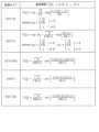
複数の変換タイプは、例えば、DCT-II、DCT-V、DCT-VIII、DST-I及びDST-VIIを含む。図3は、各変換タイプに対応する変換基底関数を示す表である。図3においてNは入力画素の数を示す。これらの複数の変換タイプの中からの変換タイプの選択は、例えば、予測の種類(イントラ予測及びインター予測)に依存してもよいし、イントラ予測モードに依存してもよい。 Multiple conversion types include, for example, DCT-II, DCT-V, DCT-VIII, DST-I, and DST-VII. FIG. 3 is a table showing transformation basis functions corresponding to each transformation type. In FIG. 3, N indicates the number of input pixels. The selection of the conversion type from among these plurality of conversion types may depend on the type of prediction (intra prediction and inter prediction) or may depend on the intra prediction mode, for example.
このようなEMT又はAMTを適用するか否かを示す情報(例えばAMTフラグと呼ばれる)及び選択された変換タイプを示す情報は、CUレベルで信号化される。なお、これらの情報の信号化は、CUレベルに限定される必要はなく、他のレベル(例えば、シーケンスレベル、ピクチャレベル、スライスレベル、タイルレベル又はCTUレベル)であってもよい。 Information indicating whether to apply such EMT or AMT (for example, called an AMT flag) and information indicating the selected transformation type are signaled at the CU level. Note that the signaling of these information does not need to be limited to the CU level, and may be at other levels (eg, sequence level, picture level, slice level, tile level, or CTU level).
また、変換部106は、変換係数(変換結果)を再変換してもよい。このような再変換は、AST(adaptive secondary transform)又はNSST(non-separable secondary transform)と呼ばれることがある。例えば、変換部106は、イントラ予測誤差に対応する変換係数のブロックに含まれるサブブロック(例えば4x4サブブロック)ごとに再変換を行う。NSSTを適用するか否かを示す情報及びNSSTに用いられる変換行列に関する情報は、CUレベルで信号化される。なお、これらの情報の信号化は、CUレベルに限定される必要はなく、他のレベル(例えば、シーケンスレベル、ピクチャレベル、スライスレベル、タイルレベル又はCTUレベル)であってもよい。 Further, the
ここで、Separableな変換とは、入力の次元の数だけ方向ごとに分離して複数回変換を行う方式であり、Non-Separableな変換とは、入力が多次元であった際に2つ以上の次元をまとめて1次元とみなして、まとめて変換を行う方式である。 Here, separable transformation is a method in which the transformation is performed multiple times by separating each direction by the number of input dimensions, and non-separable transformation is a method in which two or more transformations are performed when the input is multidimensional. This is a method in which the dimensions of are collectively regarded as one dimension and the transformation is performed collectively.
例えば、Non-Separableな変換の1例として、入力が4×4のブロックであった場合にはそれを16個の要素を持ったひとつの配列とみなし、その配列に対して16×16の変換行列で変換処理を行うようなものが挙げられる。 For example, as an example of non-separable transformation, if the input is a 4x4 block, it is treated as one array with 16 elements, and the 16x16 transformation is performed on that array. An example is something that performs a transformation process using a matrix.
また、同様に4×4の入力ブロックを16個の要素を持ったひとつの配列とみなした後に、その配列に対してGivens回転を複数回行うようなもの(Hypercube Givens Transform)もNon-Separableな変換の例である。 Similarly, Hypercube Givens Transform, which treats a 4×4 input block as one array with 16 elements and then performs Givens rotation on that array multiple times, is also Non-Separable. This is an example of conversion.
[量子化部]
量子化部108は、変換部106から出力された変換係数を量子化する。具体的には、量子化部108は、カレントブロックの変換係数を所定の走査順序で走査し、走査された変換係数に対応する量子化パラメータ(QP)に基づいて当該変換係数を量子化する。そして、量子化部108は、カレントブロックの量子化された変換係数(以下、量子化係数という)をエントロピー符号化部110及び逆量子化部112に出力する。[Quantization section]
所定の順序は、変換係数の量子化/逆量子化のための順序である。例えば、所定の走査順序は、周波数の昇順(低周波から高周波の順)又は降順(高周波から低周波の順)で定義される。 The predetermined order is the order for quantization/inverse quantization of transform coefficients. For example, the predetermined scanning order is defined as ascending order of frequency (order from low frequency to high frequency) or descending order (order from high frequency to low frequency).
量子化パラメータとは、量子化ステップ(量子化幅)を定義するパラメータである。例えば、量子化パラメータの値が増加すれば量子化ステップも増加する。つまり、量子化パラメータの値が増加すれば量子化誤差が増大する。 The quantization parameter is a parameter that defines a quantization step (quantization width). For example, if the value of the quantization parameter increases, the quantization step also increases. In other words, as the value of the quantization parameter increases, the quantization error increases.
[エントロピー符号化部]
エントロピー符号化部110は、量子化部108から入力である量子化係数を可変長符号化することにより符号化信号(符号化ビットストリーム)を生成する。具体的には、エントロピー符号化部110は、例えば、量子化係数を二値化し、二値信号を算術符号化する。[Entropy encoding unit]
[逆量子化部]
逆量子化部112は、量子化部108からの入力である量子化係数を逆量子化する。具体的には、逆量子化部112は、カレントブロックの量子化係数を所定の走査順序で逆量子化する。そして、逆量子化部112は、カレントブロックの逆量子化された変換係数を逆変換部114に出力する。[Dequantization section]
The
[逆変換部]
逆変換部114は、逆量子化部112からの入力である変換係数を逆変換することにより予測誤差を復元する。具体的には、逆変換部114は、変換係数に対して、変換部106による変換に対応する逆変換を行うことにより、カレントブロックの予測誤差を復元する。そして、逆変換部114は、復元された予測誤差を加算部116に出力する。[Inverse conversion section]
The
なお、復元された予測誤差は、量子化により情報が失われているので、減算部104が算出した予測誤差と一致しない。すなわち、復元された予測誤差には、量子化誤差が含まれている。 Note that the restored prediction error does not match the prediction error calculated by the
[加算部]
加算部116は、逆変換部114からの入力である予測誤差と予測制御部128からの入力である予測サンプルとを加算することによりカレントブロックを再構成する。そして、加算部116は、再構成されたブロックをブロックメモリ118及びループフィルタ部120に出力する。再構成ブロックは、ローカル復号ブロックと呼ばれることもある。[Addition section]
The
[ブロックメモリ]
ブロックメモリ118は、イントラ予測で参照されるブロックであって符号化対象ピクチャ(以下、カレントピクチャという)内のブロックを格納するための記憶部である。具体的には、ブロックメモリ118は、加算部116から出力された再構成ブロックを格納する。[Block memory]
The
[ループフィルタ部]
ループフィルタ部120は、加算部116によって再構成されたブロックにループフィルタを施し、フィルタされた再構成ブロックをフレームメモリ122に出力する。ループフィルタとは、符号化ループ内で用いられるフィルタ(インループフィルタ)であり、例えば、デブロッキング・フィルタ(DF)、サンプルアダプティブオフセット(SAO)及びアダプティブループフィルタ(ALF)などを含む。[Loop filter section]
The
ALFでは、符号化歪みを除去するための最小二乗誤差フィルタが適用され、例えばカレントブロック内の2x2サブブロックごとに、局所的な勾配(gradient)の方向及び活性度(activity)に基づいて複数のフィルタの中から選択された1つのフィルタが適用される。 In ALF, a least squares error filter is applied to remove coding distortion. For example, for each 2x2 subblock within the current block, multiple filters are applied based on the direction and activity of the local gradient. One filter selected from among the filters is applied.
具体的には、まず、サブブロック(例えば2x2サブブロック)が複数のクラス(例えば15又は25クラス)に分類される。サブブロックの分類は、勾配の方向及び活性度に基づいて行われる。例えば、勾配の方向値D(例えば0~2又は0~4)と勾配の活性値A(例えば0~4)とを用いて分類値C(例えばC=5D+A)が算出される。そして、分類値Cに基づいて、サブブロックが複数のクラス(例えば15又は25クラス)に分類される。 Specifically, first, a subblock (for example, a 2x2 subblock) is classified into a plurality of classes (for example, 15 or 25 classes). Classification of subblocks is performed based on gradient direction and activity. For example, the classification value C (for example, C=5D+A) is calculated using the gradient direction value D (for example, 0 to 2 or 0 to 4) and the gradient activity value A (for example, 0 to 4). Then, based on the classification value C, the sub-blocks are classified into a plurality of classes (for example, 15 or 25 classes).
勾配の方向値Dは、例えば、複数の方向(例えば水平、垂直及び2つの対角方向)の勾配を比較することにより導出される。また、勾配の活性値Aは、例えば、複数の方向の勾配を加算し、加算結果を量子化することにより導出される。 The gradient direction value D is derived, for example, by comparing gradients in multiple directions (eg, horizontal, vertical, and two diagonal directions). Further, the activation value A of the gradient is derived, for example, by adding gradients in a plurality of directions and quantizing the addition result.
このような分類の結果に基づいて、複数のフィルタの中からサブブロックのためのフィルタが決定される。 Based on the results of such classification, a filter for the sub-block is determined from among the plurality of filters.
ALFで用いられるフィルタの形状としては例えば円対称形状が利用される。図4A~図4Cは、ALFで用いられるフィルタの形状の複数の例を示す図である。図4Aは、5x5ダイヤモンド形状フィルタを示し、図4Bは、7x7ダイヤモンド形状フィルタを示し、図4Cは、9x9ダイヤモンド形状フィルタを示す。フィルタの形状を示す情報は、ピクチャレベルで信号化される。なお、フィルタの形状を示す情報の信号化は、ピクチャレベルに限定される必要はなく、他のレベル(例えば、シーケンスレベル、スライスレベル、タイルレベル、CTUレベル又はCUレベル)であってもよい。 For example, a circularly symmetrical shape is used as the shape of the filter used in ALF. 4A to 4C are diagrams showing a plurality of examples of filter shapes used in ALF. Figure 4A shows a 5x5 diamond shaped filter, Figure 4B shows a 7x7 diamond shaped filter, and Figure 4C shows a 9x9 diamond shaped filter. Information indicating the shape of the filter is signaled at the picture level. Note that the signalization of information indicating the shape of the filter does not need to be limited to the picture level, and may be at other levels (eg, sequence level, slice level, tile level, CTU level, or CU level).
ALFのオン/オフは、例えば、ピクチャレベル又はCUレベルで決定される。例えば、輝度についてはCUレベルでALFを適用するか否かが決定され、色差についてはピクチャレベルでALFを適用するか否かが決定される。ALFのオン/オフを示す情報は、ピクチャレベル又はCUレベルで信号化される。なお、ALFのオン/オフを示す情報の信号化は、ピクチャレベル又はCUレベルに限定される必要はなく、他のレベル(例えば、シーケンスレベル、スライスレベル、タイルレベル又はCTUレベル)であってもよい。 ALF on/off is determined, for example, at the picture level or the CU level. For example, for brightness, it is determined whether to apply ALF at the CU level, and for color difference, it is determined whether to apply ALF at the picture level. Information indicating whether the ALF is on or off is signaled at the picture level or CU level. Note that the signaling of information indicating ALF on/off need not be limited to the picture level or CU level, and may be made at other levels (for example, sequence level, slice level, tile level, or CTU level). good.
選択可能な複数のフィルタ(例えば15又は25までのフィルタ)の係数セットは、ピクチャレベルで信号化される。なお、係数セットの信号化は、ピクチャレベルに限定される必要はなく、他のレベル(例えば、シーケンスレベル、スライスレベル、タイルレベル、CTUレベル、CUレベル又はサブブロックレベル)であってもよい。 Coefficient sets of selectable multiple filters (eg, up to 15 or 25 filters) are signaled at the picture level. Note that the signaling of the coefficient set need not be limited to the picture level, and may be at other levels (eg, sequence level, slice level, tile level, CTU level, CU level, or subblock level).
[フレームメモリ]
フレームメモリ122は、インター予測に用いられる参照ピクチャを格納するための記憶部であり、フレームバッファと呼ばれることもある。具体的には、フレームメモリ122は、ループフィルタ部120によってフィルタされた再構成ブロックを格納する。[Frame memory]
The
[イントラ予測部]
イントラ予測部124は、ブロックメモリ118に格納されたカレントピクチャ内のブロックを参照してカレントブロックのイントラ予測(画面内予測ともいう)を行うことで、予測信号(イントラ予測信号)を生成する。具体的には、イントラ予測部124は、カレントブロックに隣接するブロックのサンプル(例えば輝度値、色差値)を参照してイントラ予測を行うことでイントラ予測信号を生成し、イントラ予測信号を予測制御部128に出力する。[Intra prediction section]
The
例えば、イントラ予測部124は、予め規定された複数のイントラ予測モードのうちの1つを用いてイントラ予測を行う。複数のイントラ予測モードは、1以上の非方向性予測モードと、複数の方向性予測モードと、を含む。 For example, the
1以上の非方向性予測モードは、例えばH.265/HEVC(High-Efficiency Video Coding)規格(非特許文献1)で規定されたPlanar予測モード及びDC予測モードを含む。 One or more non-directional prediction modes may be used, for example, in H. This includes a Planar prediction mode and a DC prediction mode defined in the H.265/HEVC (High-Efficiency Video Coding) standard (Non-Patent Document 1).
複数の方向性予測モードは、例えばH.265/HEVC規格で規定された33方向の予測モードを含む。なお、複数の方向性予測モードは、33方向に加えてさらに32方向の予測モード(合計で65個の方向性予測モード)を含んでもよい。図5Aは、イントラ予測における67個のイントラ予測モード(2個の非方向性予測モード及び65個の方向性予測モード)を示す図である。実線矢印は、H.265/HEVC規格で規定された33方向を表し、破線矢印は、追加された32方向を表す。 Multiple directional prediction modes are available, for example in H. This includes prediction modes in 33 directions defined by the H.265/HEVC standard. Note that the plurality of directional prediction modes may include prediction modes in 32 directions in addition to the 33 directions (65 directional prediction modes in total). FIG. 5A is a diagram showing 67 intra prediction modes (2 non-directional prediction modes and 65 directional prediction modes) in intra prediction. Solid arrows indicate H. The dashed arrows represent the 33 directions defined in the H.265/HEVC standard, and the dashed arrows represent the added 32 directions.
なお、色差ブロックのイントラ予測において、輝度ブロックが参照されてもよい。つまり、カレントブロックの輝度成分に基づいて、カレントブロックの色差成分が予測されてもよい。このようなイントラ予測は、CCLM(cross-component linear model)予測と呼ばれることがある。このような輝度ブロックを参照する色差ブロックのイントラ予測モード(例えばCCLMモードと呼ばれる)は、色差ブロックのイントラ予測モードの1つとして加えられてもよい。 Note that the luminance block may be referenced in the intra prediction of the chrominance block. That is, the chrominance component of the current block may be predicted based on the luminance component of the current block. Such intra prediction is sometimes called cross-component linear model (CCLM) prediction. An intra prediction mode for a chrominance block that refers to such a luminance block (for example, referred to as a CCLM mode) may be added as one of the intra prediction modes for a chrominance block.
イントラ予測部124は、水平/垂直方向の参照画素の勾配に基づいてイントラ予測後の画素値を補正してもよい。このような補正をともなうイントラ予測は、PDPC(position dependent intra prediction combination)と呼ばれることがある。PDPCの適用の有無を示す情報(例えばPDPCフラグと呼ばれる)は、例えばCUレベルで信号化される。なお、この情報の信号化は、CUレベルに限定される必要はなく、他のレベル(例えば、シーケンスレベル、ピクチャレベル、スライスレベル、タイルレベル又はCTUレベル)であってもよい。 The
[インター予測部]
インター予測部126は、フレームメモリ122に格納された参照ピクチャであってカレントピクチャとは異なる参照ピクチャを参照してカレントブロックのインター予測(画面間予測ともいう)を行うことで、予測信号(インター予測信号)を生成する。インター予測は、カレントブロック又はカレントブロック内のサブブロック(例えば4x4ブロック)の単位で行われる。例えば、インター予測部126は、カレントブロック又はサブブロックについて参照ピクチャ内で動き探索(motion estimation)を行う。そして、インター予測部126は、動き探索により得られた動き情報(例えば動きベクトル)を用いて動き補償を行うことでカレントブロック又はサブブロックのインター予測信号を生成する。そして、インター予測部126は、生成されたインター予測信号を予測制御部128に出力する。[Inter prediction unit]
The
動き補償に用いられた動き情報は信号化される。動きベクトルの信号化には、予測動きベクトル(motion vector predictor)が用いられてもよい。つまり、動きベクトルと予測動きベクトルとの間の差分が信号化されてもよい。 The motion information used for motion compensation is converted into a signal. A motion vector predictor may be used to signal the motion vector. That is, the difference between the motion vector and the predicted motion vector may be converted into a signal.
なお、動き探索により得られたカレントブロックの動き情報だけでなく、隣接ブロックの動き情報も用いて、インター予測信号が生成されてもよい。具体的には、動き探索により得られた動き情報に基づく予測信号と、隣接ブロックの動き情報に基づく予測信号と、を重み付け加算することにより、カレントブロック内のサブブロック単位でインター予測信号が生成されてもよい。このようなインター予測(動き補償)は、OBMC(overlapped block motion compensation)と呼ばれることがある。 Note that the inter prediction signal may be generated using not only the motion information of the current block obtained by motion search but also the motion information of adjacent blocks. Specifically, an inter-predicted signal is generated for each sub-block within the current block by weighted addition of a predicted signal based on motion information obtained by motion search and a predicted signal based on motion information of adjacent blocks. may be done. Such inter prediction (motion compensation) is sometimes called OBMC (overlapped block motion compensation).
このようなOBMCモードでは、OBMCのためのサブブロックのサイズを示す情報(例えばOBMCブロックサイズと呼ばれる)は、シーケンスレベルで信号化される。また、OBMCモードを適用するか否かを示す情報(例えばOBMCフラグと呼ばれる)は、CUレベルで信号化される。なお、これらの情報の信号化のレベルは、シーケンスレベル及びCUレベルに限定される必要はなく、他のレベル(例えばピクチャレベル、スライスレベル、タイルレベル、CTUレベル又はサブブロックレベル)であってもよい。 In such an OBMC mode, information indicating the size of sub-blocks for OBMC (eg called OBMC block size) is signaled at the sequence level. Furthermore, information indicating whether or not to apply the OBMC mode (for example, called an OBMC flag) is signaled at the CU level. Note that the level of signalization of this information is not limited to the sequence level and CU level, and may be at other levels (for example, picture level, slice level, tile level, CTU level, or subblock level). good.
OBMCモードについて、より具体的に説明する。図5B及び図5Cは、OBMC処理による予測画像補正処理の概要を説明するためのフローチャート及び概念図である。 The OBMC mode will be explained in more detail. FIGS. 5B and 5C are a flowchart and a conceptual diagram for explaining an overview of predicted image correction processing using OBMC processing.
まず、符号化対象ブロックに割り当てられた動きベクトル(MV)を用いて通常の動き補償による予測画像(Pred)を取得する。 First, a predicted image (Pred) by normal motion compensation is obtained using a motion vector (MV) assigned to a block to be encoded.
次に、符号化済みの左隣接ブロックの動きベクトル(MV_L)を符号化対象ブロックに適用して予測画像(Pred_L)を取得し、前記予測画像とPred_Lとを重みを付けて重ね合わせることで予測画像の1回目の補正を行う。 Next, the motion vector (MV_L) of the encoded left adjacent block is applied to the current block to be encoded to obtain a predicted image (Pred_L), and the predicted image and Pred_L are overlaid with weights to make a prediction. Perform the first correction of the image.
同様に、符号化済みの上隣接ブロックの動きベクトル(MV_U)を符号化対象ブロックに適用して予測画像(Pred_U)を取得し、前記1回目の補正を行った予測画像とPred_Uとを重みを付けて重ね合わせることで予測画像の2回目の補正を行い、それを最終的な予測画像とする。 Similarly, the motion vector (MV_U) of the encoded upper adjacent block is applied to the block to be encoded to obtain a predicted image (Pred_U), and the predicted image subjected to the first correction and Pred_U are weighted. By adding and superimposing the images, the predicted image is corrected a second time, and this is used as the final predicted image.
なお、ここでは左隣接ブロックと上隣接ブロックを用いた2段階の補正の方法を説明したが、右隣接ブロックや下隣接ブロックを用いて2段階よりも多い回数の補正を行う構成とすることも可能である。 Note that although a two-stage correction method using the left adjacent block and the upper adjacent block has been described here, it is also possible to adopt a configuration in which correction is performed more times than two stages using the right adjacent block and the lower adjacent block. It is possible.
なお、重ね合わせを行う領域はブロック全体の画素領域ではなく、ブロック境界近傍の一部の領域のみであってもよい。 Note that the region to be superimposed may not be the pixel region of the entire block, but only a part of the region near the block boundary.
なお、ここでは1枚の参照ピクチャからの予測画像補正処理について説明したが、複数枚の参照ピクチャから予測画像を補正する場合も同様であり、各々の参照ピクチャから補正した予測画像を取得した後に、得られた予測画像をさらに重ね合わせることで最終的な予測画像とする。 Note that although we have described the predicted image correction process from one reference picture, the same applies when correcting the predicted image from multiple reference pictures, and after acquiring the corrected predicted image from each reference picture, , the obtained predicted images are further superimposed to form a final predicted image.
なお、前記処理対象ブロックは、予測ブロック単位であっても、予測ブロックをさらに分割したサブブロック単位であってもよい。 Note that the processing target block may be in units of prediction blocks or in units of subblocks obtained by further dividing the prediction block.
OBMC処理を適用するかどうかの判定の方法として、例えば、OBMC処理を適用するかどうかを示す信号であるobmc_flagを用いる方法がある。具体的な一例としては、符号化装置において、符号化対象ブロックが動きの複雑な領域に属しているかどうかを判定し、動きの複雑な領域に属している場合はobmc_flagとして値1を設定してOBMC処理を適用して符号化を行い、動きの複雑な領域に属していない場合はobmc_flagとして値0を設定してOBMC処理を適用せずに符号化を行う。一方、復号装置では、ストリームに記述されたobmc_flagを復号することで、その値に応じてOBMC処理を適用するかどうかを切替えて復号を行う。 As a method for determining whether to apply OBMC processing, for example, there is a method using obmc_flag, which is a signal indicating whether to apply OBMC processing. As a specific example, the encoding device determines whether the block to be encoded belongs to an area with complex motion, and if it belongs to the area with complex motion, sets the
なお、動き情報は信号化されずに、復号装置側で導出されてもよい。例えば、H.265/HEVC規格で規定されたマージモードが用いられてもよい。また例えば、復号装置側で動き探索を行うことにより動き情報が導出されてもよい。この場合、カレントブロックの画素値を用いずに動き探索が行われる。 Note that the motion information may be derived on the decoding device side without being converted into a signal. For example, H. The merge mode defined in the H.265/HEVC standard may be used. Further, for example, motion information may be derived by performing a motion search on the decoding device side. In this case, motion search is performed without using the pixel values of the current block.
ここで、復号装置側で動き探索を行うモードについて説明する。この復号装置側で動き探索を行うモードは、PMMVD(pattern matched motion vector derivation)モード又はFRUC(frame rate up-conversion)モードと呼ばれることがある。 Here, a mode in which motion search is performed on the decoding device side will be explained. This mode in which motion search is performed on the decoding device side is sometimes called PMMVD (pattern matched motion vector derivation) mode or FRUC (frame rate up-conversion) mode.
FRUC処理の一例を図5Dに示す。まず、カレントブロックに空間的又は時間的に隣接する符号化済みブロックの動きベクトルを参照して、各々が予測動きベクトルを有する複数の候補のリスト(マージリストと共通であってもよい)が生成される。次に、候補リストに登録されている複数の候補MVの中からベスト候補MVを選択する。例えば、候補リストに含まれる各候補の評価値が算出され、評価値に基づいて1つの候補が選択される。 An example of FRUC processing is shown in FIG. 5D. First, by referring to the motion vectors of encoded blocks that are spatially or temporally adjacent to the current block, a list of multiple candidates (which may be the same as a merge list) each having a predicted motion vector is generated. be done. Next, the best candidate MV is selected from among the plurality of candidate MVs registered in the candidate list. For example, the evaluation value of each candidate included in the candidate list is calculated, and one candidate is selected based on the evaluation value.
そして、選択された候補の動きベクトルに基づいて、カレントブロックのための動きベクトルが導出される。具体的には、例えば、選択された候補の動きベクトル(ベスト候補MV)がそのままカレントブロックのための動きベクトルとして導出される。また例えば、選択された候補の動きベクトルに対応する参照ピクチャ内の位置の周辺領域において、パターンマッチングを行うことにより、カレントブロックのための動きベクトルが導出されてもよい。すなわち、ベスト候補MVの周辺の領域に対して同様の方法で探索を行い、さらに評価値が良い値となるMVがあった場合は、ベスト候補MVを前記MVに更新して、それをカレントブロックの最終的なMVとしてもよい。なお、当該処理を実施しない構成とすることも可能である。 A motion vector for the current block is then derived based on the motion vector of the selected candidate. Specifically, for example, the motion vector of the selected candidate (best candidate MV) is directly derived as the motion vector for the current block. Furthermore, for example, a motion vector for the current block may be derived by performing pattern matching in a region surrounding a position in the reference picture that corresponds to the selected candidate motion vector. That is, a similar method is used to search the area around the best candidate MV, and if there is an MV with a better evaluation value, the best candidate MV is updated to the above MV and it is used as the current block. It may also be used as the final MV. Note that it is also possible to have a configuration in which this process is not performed.
サブブロック単位で処理を行う場合も全く同様の処理としてもよい。 Exactly the same process may be used when processing is performed in sub-block units.
なお、評価値は、動きベクトルに対応する参照ピクチャ内の領域と、所定の領域との間のパターンマッチングによって再構成画像の差分値を求めることにより算出される。なお、差分値に加えてそれ以外の情報を用いて評価値を算出してもよい。 Note that the evaluation value is calculated by determining the difference value of the reconstructed image by pattern matching between a region in the reference picture corresponding to the motion vector and a predetermined region. Note that the evaluation value may be calculated using information other than the difference value.
パターンマッチングとしては、第1パターンマッチング又は第2パターンマッチングが用いられる。第1パターンマッチング及び第2パターンマッチングは、それぞれ、バイラテラルマッチング(bilateral matching)及びテンプレートマッチング(template matching)と呼ばれることがある。 As the pattern matching, first pattern matching or second pattern matching is used. The first pattern matching and the second pattern matching may be referred to as bilateral matching and template matching, respectively.
第1パターンマッチングでは、異なる2つの参照ピクチャ内の2つのブロックであってカレントブロックの動き軌道(motion trajectory)に沿う2つのブロックの間でパターンマッチングが行われる。したがって、第1パターンマッチングでは、上述した候補の評価値の算出のための所定の領域として、カレントブロックの動き軌道に沿う他の参照ピクチャ内の領域が用いられる。 In the first pattern matching, pattern matching is performed between two blocks in two different reference pictures that are along the motion trajectory of the current block. Therefore, in the first pattern matching, a region in another reference picture along the motion trajectory of the current block is used as a predetermined region for calculating the candidate evaluation value described above.
図6は、動き軌道に沿う2つのブロック間でのパターンマッチング(バイラテラルマッチング)の一例を説明するための図である。図6に示すように、第1パターンマッチングでは、カレントブロック(Cur block)の動き軌道に沿う2つのブロックであって異なる2つの参照ピクチャ(Ref0、Ref1)内の2つのブロックのペアの中で最もマッチするペアを探索することにより2つの動きベクトル(MV0、MV1)が導出される。具体的には、カレントブロックに対して、候補MVで指定された第1の符号化済み参照ピクチャ(Ref0)内の指定位置における再構成画像と、前記候補MVを表示時間間隔でスケーリングした対称MVで指定された第2の符号化済み参照ピクチャ(Ref1)内の指定位置における再構成画像との差分を導出し、得られた差分値を用いて評価値を算出する。複数の候補MVの中で最も評価値が良い値となる候補MVを最終MVとして選択するとよい。 FIG. 6 is a diagram for explaining an example of pattern matching (bilateral matching) between two blocks along a motion trajectory. As shown in FIG. 6, in the first pattern matching, two blocks along the motion trajectory of the current block (Cur block) are found in a pair of two blocks in two different reference pictures (Ref0, Ref1). Two motion vectors (MV0, MV1) are derived by searching for the best matching pair. Specifically, for the current block, a reconstructed image at a specified position in the first coded reference picture (Ref0) specified by a candidate MV, and a symmetric MV obtained by scaling the candidate MV at a display time interval. The difference between the reconstructed image and the specified position in the second encoded reference picture (Ref1) specified by is derived, and the evaluation value is calculated using the obtained difference value. It is preferable to select the candidate MV with the best evaluation value among the plurality of candidate MVs as the final MV.
連続的な動き軌道の仮定の下では、2つの参照ブロックを指し示す動きベクトル(MV0、MV1)は、カレントピクチャ(Cur Pic)と2つの参照ピクチャ(Ref0、Ref1)との間の時間的な距離(TD0、TD1)に対して比例する。例えば、カレントピクチャが時間的に2つの参照ピクチャの間に位置し、カレントピクチャから2つの参照ピクチャへの時間的な距離が等しい場合、第1パターンマッチングでは、鏡映対称な双方向の動きベクトルが導出される。 Under the assumption of continuous motion trajectory, the motion vectors (MV0, MV1) pointing to two reference blocks are determined by the temporal distance between the current picture (Cur Pic) and the two reference pictures (Ref0, Ref1). It is proportional to (TD0, TD1). For example, if the current picture is temporally located between two reference pictures and the temporal distances from the current picture to the two reference pictures are equal, the first pattern matching uses a mirror-symmetric bidirectional motion vector. is derived.
第2パターンマッチングでは、カレントピクチャ内のテンプレート(カレントピクチャ内でカレントブロックに隣接するブロック(例えば上及び/又は左隣接ブロック))と参照ピクチャ内のブロックとの間でパターンマッチングが行われる。したがって、第2パターンマッチングでは、上述した候補の評価値の算出のための所定の領域として、カレントピクチャ内のカレントブロックに隣接するブロックが用いられる。 In the second pattern matching, pattern matching is performed between a template in the current picture (a block adjacent to the current block in the current picture (eg, an upper and/or left adjacent block)) and a block in the reference picture. Therefore, in the second pattern matching, a block adjacent to the current block in the current picture is used as a predetermined area for calculating the candidate evaluation value described above.
図7は、カレントピクチャ内のテンプレートと参照ピクチャ内のブロックとの間でのパターンマッチング(テンプレートマッチング)の一例を説明するための図である。図7に示すように、第2パターンマッチングでは、カレントピクチャ(Cur Pic)内でカレントブロック(Cur block)に隣接するブロックと最もマッチするブロックを参照ピクチャ(Ref0)内で探索することによりカレントブロックの動きベクトルが導出される。具体的には、カレントブロックに対して、左隣接及び上隣接の両方もしくはどちらか一方の符号化済み領域の再構成画像と、候補MVで指定された符号化済み参照ピクチャ(Ref0)内の同等位置における再構成画像との差分を導出し、得られた差分値を用いて評価値を算出し、複数の候補MVの中で最も評価値が良い値となる候補MVをベスト候補MVとして選択するとよい。 FIG. 7 is a diagram for explaining an example of pattern matching (template matching) between a template in the current picture and a block in the reference picture. As shown in FIG. 7, in the second pattern matching, the current block is searched in the reference picture (Ref0) for the block that most matches the block adjacent to the current block (Cur block) in the current picture (Cur Pic). A motion vector of is derived. Specifically, for the current block, the reconstructed image of the left adjacent and/or upper adjacent encoded area and the equivalent image in the encoded reference picture (Ref0) specified by the candidate MV. The difference between the position and the reconstructed image is derived, the obtained difference value is used to calculate the evaluation value, and the candidate MV with the best evaluation value among the multiple candidate MVs is selected as the best candidate MV. good.
このようなFRUCモードを適用するか否かを示す情報(例えばFRUCフラグと呼ばれる)は、CUレベルで信号化される。また、FRUCモードが適用される場合(例えばFRUCフラグが真の場合)、パターンマッチングの方法(第1パターンマッチング又は第2パターンマッチング)を示す情報(例えばFRUCモードフラグと呼ばれる)がCUレベルで信号化される。なお、これらの情報の信号化は、CUレベルに限定される必要はなく、他のレベル(例えば、シーケンスレベル、ピクチャレベル、スライスレベル、タイルレベル、CTUレベル又はサブブロックレベル)であってもよい。 Information indicating whether to apply such a FRUC mode (for example, called a FRUC flag) is signaled at the CU level. In addition, when the FRUC mode is applied (for example, when the FRUC flag is true), information indicating the pattern matching method (first pattern matching or second pattern matching) (for example, called the FRUC mode flag) is signaled at the CU level. be converted into Note that the signaling of these information is not limited to the CU level, and may be at other levels (e.g., sequence level, picture level, slice level, tile level, CTU level, or subblock level). .
ここで、等速直線運動を仮定したモデルに基づいて動きベクトルを導出するモードについて説明する。このモードは、BIO(bi-directional optical
flow)モードと呼ばれることがある。Here, a mode for deriving a motion vector based on a model assuming uniform linear motion will be described. This mode is a BIO (bi-directional optical
flow) mode.
図8は、等速直線運動を仮定したモデルを説明するための図である。図8において、(vx,vy)は、速度ベクトルを示し、τ0、τ1は、それぞれ、カレントピクチャ(Cur Pic)と2つの参照ピクチャ(Ref0,Ref1)との間の時間的な距離を示す。(MVx0,MVy0)は、参照ピクチャRef0に対応する動きベクトルを示し、(MVx1、MVy1)は、参照ピクチャRef1に対応する動きベクトルを示す。FIG. 8 is a diagram for explaining a model assuming uniform linear motion. In FIG. 8, (vx , vy ) represent velocity vectors, and τ0 and τ1 are the times between the current picture (Cur Pic) and two reference pictures (Ref0 , Ref1 ), respectively. distance. (MVx0 , MVy0 ) indicates a motion vector corresponding to the reference picture Ref0 , and (MVx1 , MVy1 ) indicates a motion vector corresponding to the reference picture Ref1 .
このとき速度ベクトル(vx,vy)の等速直線運動の仮定の下では、(MVx0,MVy0)及び(MVx1,MVy1)は、それぞれ、(vxτ0,vyτ0)及び(-vxτ1,-vyτ1)と表され、以下のオプティカルフロー等式(1)が成り立つ。At this time, under the assumption of uniform linear motion of the velocity vector (vx , vy ), (MVx0 , MVy0 ) and (MVx1 , MVy1 ) are respectively (vx τ0 , vy τ0 ) and (-vx τ1 , -vy τ1 ), and the following optical flow equation (1) holds.

ここで、I(k)は、動き補償後の参照画像k(k=0,1)の輝度値を示す。このオプティカルフロー等式は、(i)輝度値の時間微分と、(ii)水平方向の速度及び参照画像の空間勾配の水平成分の積と、(iii)垂直方向の速度及び参照画像の空間勾配の垂直成分の積と、の和が、ゼロと等しいことを示す。このオプティカルフロー等式とエルミート補間(Hermite interpolation)との組み合わせに基づいて、マージリスト等から得られるブロック単位の動きベクトルが画素単位で補正される。Here, I(k) indicates the luminance value of the reference image k (k=0, 1) after motion compensation. This optical flow equation is the product of (i) the time derivative of the luminance value, (ii) the horizontal component of the horizontal velocity and the spatial gradient of the reference image, and (iii) the vertical velocity and the spatial gradient of the reference image. Show that the product of the vertical components of and the sum of are equal to zero. Based on the combination of this optical flow equation and Hermite interpolation, a motion vector in units of blocks obtained from a merge list or the like is corrected in units of pixels.
なお、等速直線運動を仮定したモデルに基づく動きベクトルの導出とは異なる方法で、復号装置側で動きベクトルが導出されてもよい。例えば、複数の隣接ブロックの動きベクトルに基づいてサブブロック単位で動きベクトルが導出されてもよい。 Note that a motion vector may be derived on the decoding device side using a method different from deriving a motion vector based on a model assuming uniform linear motion. For example, a motion vector may be derived for each subblock based on motion vectors of a plurality of adjacent blocks.
ここで、複数の隣接ブロックの動きベクトルに基づいてサブブロック単位で動きベクトルを導出するモードについて説明する。このモードは、アフィン動き補償予測(affine motion compensation prediction)モードと呼ばれることがある。 Here, a mode in which a motion vector is derived for each subblock based on motion vectors of a plurality of adjacent blocks will be described. This mode is sometimes referred to as affine motion compensation prediction mode.
図9Aは、複数の隣接ブロックの動きベクトルに基づくサブブロック単位の動きベクトルの導出を説明するための図である。図9Aにおいて、カレントブロックは、16の4x4サブブロックを含む。ここでは、隣接ブロックの動きベクトルに基づいてカレントブロックの左上角制御ポイントの動きベクトルv0が導出され、隣接サブブロックの動きベクトルに基づいてカレントブロックの右上角制御ポイントの動きベクトルv1が導出される。そして、2つの動きベクトルv0及びv1を用いて、以下の式(2)により、カレントブロック内の各サブブロックの動きベクトル(vx,vy)が導出される。FIG. 9A is a diagram for explaining derivation of a motion vector in sub-block units based on motion vectors of a plurality of adjacent blocks. In FIG. 9A, the current block includes 16 4x4 subblocks. Here, the motion vector v0 of the upper left corner control point of the current block is derived based on the motion vector of the adjacent block, and the motion vector v1 of the upper right corner control point of the current block is derived based on the motion vector of the adjacent sub-block. be done. Then, using the two motion vectors v0 and v1 , the motion vector (vx , vy ) of each sub-block within the current block is derived by the following equation (2).

ここで、x及びyは、それぞれ、サブブロックの水平位置及び垂直位置を示し、wは、予め定められた重み係数を示す。 Here, x and y indicate the horizontal and vertical positions of the subblock, respectively, and w indicates a predetermined weighting factor.
このようなアフィン動き補償予測モードでは、左上及び右上角制御ポイントの動きベクトルの導出方法が異なるいくつかのモードを含んでもよい。このようなアフィン動き補償予測モードを示す情報(例えばアフィンフラグと呼ばれる)は、CUレベルで信号化される。なお、このアフィン動き補償予測モードを示す情報の信号化は、CUレベルに限定される必要はなく、他のレベル(例えば、シーケンスレベル、ピクチャレベル、スライスレベル、タイルレベル、CTUレベル又はサブブロックレベル)であってもよい。 Such affine motion compensation prediction modes may include several modes in which the motion vectors of the upper left and upper right corner control points are derived from different methods. Information indicating such an affine motion compensation prediction mode (for example, called an affine flag) is signaled at the CU level. Note that the signaling of information indicating this affine motion compensation prediction mode does not need to be limited to the CU level, and may be signaled at other levels (e.g., sequence level, picture level, slice level, tile level, CTU level, or subblock level). ).
[予測制御部]
予測制御部128は、イントラ予測信号及びインター予測信号のいずれかを選択し、選択した信号を予測信号として減算部104及び加算部116に出力する。[Predictive control unit]
The
ここで、マージモードにより符号化対象ピクチャの動きベクトルを導出する例を説明する。図9Bは、マージモードによる動きベクトル導出処理の概要を説明するための図である。 Here, an example of deriving a motion vector of a picture to be encoded using merge mode will be described. FIG. 9B is a diagram for explaining an overview of motion vector derivation processing in merge mode.
まず、予測MVの候補を登録した予測MVリストを生成する。予測MVの候補としては、符号化対象ブロックの空間的に周辺に位置する複数の符号化済みブロックが持つMVである空間隣接予測MV、符号化済み参照ピクチャにおける符号化対象ブロックの位置を投影した近辺のブロックが持つMVである時間隣接予測MV、空間隣接予測MVと時間隣接予測MVのMV値を組合わせて生成したMVである結合予測MV、及び値がゼロのMVであるゼロ予測MV等がある。 First, a predicted MV list in which predicted MV candidates are registered is generated. Candidates for the predicted MV include spatially adjacent predicted MVs that are MVs of multiple encoded blocks spatially located around the current block, and spatially adjacent predicted MVs that are the MVs of multiple encoded blocks spatially located around the current block, and the projected position of the current block in the encoded reference picture. A temporally adjacent predicted MV which is an MV of a nearby block, a combined predicted MV which is an MV generated by combining the MV values of a spatially adjacent predicted MV and a temporally adjacent predicted MV, and a zero predicted MV which is an MV whose value is zero, etc. There is.
次に、予測MVリストに登録されている複数の予測MVの中から1つの予測MVを選択することで、符号化対象ブロックのMVとして決定する。 Next, one predicted MV is selected from among the plurality of predicted MVs registered in the predicted MV list, thereby determining it as the MV of the current block to be encoded.
さらに可変長符号化部では、どの予測MVを選択したかを示す信号であるmerge_idxをストリームに記述して符号化する。 Further, in the variable length encoding unit, merge_idx, which is a signal indicating which predicted MV has been selected, is written in the stream and encoded.
なお、図9Bで説明した予測MVリストに登録する予測MVは一例であり、図中の個数とは異なる個数であったり、図中の予測MVの一部の種類を含まない構成であったり、図中の予測MVの種類以外の予測MVを追加した構成であったりしてもよい。 Note that the predicted MVs registered in the predicted MV list explained in FIG. 9B are just an example, and the number of predicted MVs registered in the predicted MV list explained in FIG. A configuration may also be adopted in which predicted MVs other than the types of predicted MVs shown in the figure are added.
なお、マージモードにより導出した符号化対象ブロックのMVを用いて、後述するDMVR処理を行うことによって最終的なMVを決定してもよい。 Note that the final MV may be determined by performing DMVR processing, which will be described later, using the MV of the encoding target block derived by the merge mode.
ここで、DMVR処理を用いてMVを決定する例について説明する。 Here, an example of determining MV using DMVR processing will be described.
図9Cは、DMVR処理の概要を説明するための概念図である。 FIG. 9C is a conceptual diagram for explaining an overview of DMVR processing.
まず、処理対象ブロックに設定された最適MVPを候補MVとして、前記候補MVに従って、L0方向の処理済みピクチャである第1参照ピクチャ、及びL1方向の処理済みピクチャである第2参照ピクチャから参照画素をそれぞれ取得し、各参照画素の平均をとることでテンプレートを生成する。 First, using the optimal MVP set for the processing target block as a candidate MV, reference pixels are selected from a first reference picture, which is a processed picture in the L0 direction, and a second reference picture, which is a processed picture in the L1 direction, according to the candidate MV. A template is generated by acquiring each pixel and taking the average of each reference pixel.
次に、前記テンプレートを用いて、第1参照ピクチャ及び第2参照ピクチャの候補MVの周辺領域をそれぞれ探索し、最もコストが最小となるMVを最終的なMVとして決定する。なお、コスト値はテンプレートの各画素値と探索領域の各画素値との差分値及びMV値等を用いて算出する。 Next, using the template, the surrounding areas of the candidate MVs of the first reference picture and the second reference picture are searched, and the MV with the lowest cost is determined as the final MV. Note that the cost value is calculated using the difference value between each pixel value of the template and each pixel value of the search area, the MV value, etc.
なお、符号化装置及び復号装置では、ここで説明した処理の概要は基本的に共通である。 Note that the outline of the processing described here is basically the same in the encoding device and the decoding device.
なお、ここで説明した処理そのものでなくても、候補MVの周辺を探索して最終的なMVを導出することができる処理であれば、他の処理を用いてもよい。 Note that other processing may be used, other than the processing described here, as long as the processing can search around the candidate MV and derive the final MV.
ここで、LIC処理を用いて予測画像を生成するモードについて説明する。 Here, a mode for generating a predicted image using LIC processing will be described.
図9Dは、LIC処理による輝度補正処理を用いた予測画像生成方法の概要を説明するための図である。 FIG. 9D is a diagram for explaining an overview of a predicted image generation method using brightness correction processing by LIC processing.
まず、符号化済みピクチャである参照ピクチャから符号化対象ブロックに対応する参照画像を取得するためのMVを導出する。 First, an MV for acquiring a reference image corresponding to a block to be encoded is derived from a reference picture that is an encoded picture.
次に、符号化対象ブロックに対して、左隣接及び上隣接の符号化済み周辺参照領域の輝度画素値と、MVで指定された参照ピクチャ内の同等位置における輝度画素値とを用いて、参照ピクチャと符号化対象ピクチャとで輝度値がどのように変化したかを示す情報を抽出して輝度補正パラメータを算出する。 Next, for the current block to be encoded, the reference A brightness correction parameter is calculated by extracting information indicating how the brightness value has changed between the picture and the picture to be encoded.
MVで指定された参照ピクチャ内の参照画像に対して前記輝度補正パラメータを用いて輝度補正処理を行うことで、符号化対象ブロックに対する予測画像を生成する。 A predicted image for the current block to be encoded is generated by performing brightness correction processing on a reference image in a reference picture specified by the MV using the brightness correction parameter.
なお、図9Dにおける前記周辺参照領域の形状は一例であり、これ以外の形状を用いてもよい。 Note that the shape of the peripheral reference area in FIG. 9D is an example, and other shapes may be used.
また、ここでは1枚の参照ピクチャから予測画像を生成する処理について説明したが、複数枚の参照ピクチャから予測画像を生成する場合も同様であり、各々の参照ピクチャから取得した参照画像に同様の方法で輝度補正処理を行ってから予測画像を生成する。 In addition, although we have described the process of generating a predicted image from one reference picture, the process is similar when generating a predicted image from multiple reference pictures. A predicted image is generated after performing brightness correction processing using the method.
LIC処理を適用するかどうかの判定の方法として、例えば、LIC処理を適用するかどうかを示す信号であるlic_flagを用いる方法がある。具体的な一例としては、符号化装置において、符号化対象ブロックが輝度変化が発生している領域に属しているかどうかを判定し、輝度変化が発生している領域に属している場合はlic_flagとして値1を設定してLIC処理を適用して符号化を行い、輝度変化が発生している領域に属していない場合はlic_flagとして値0を設定してLIC処理を適用せずに符号化を行う。一方、復号装置では、ストリームに記述されたlic_flagを復号することで、その値に応じてLIC処理を適用するかどうかを切替えて復号を行う。 As a method for determining whether to apply LIC processing, for example, there is a method using lic_flag, which is a signal indicating whether to apply LIC processing. As a specific example, the encoding device determines whether the block to be encoded belongs to an area where a brightness change has occurred, and if it belongs to an area where a brightness change has occurred, it is set as lic_flag. Set the
LIC処理を適用するかどうかの判定の別の方法として、例えば、周辺ブロックでLIC処理を適用したかどうかに従って判定する方法もある。具体的な一例としては、符号化対象ブロックがマージモードであった場合、マージモード処理におけるMVの導出の際に選択した周辺の符号化済みブロックがLIC処理を適用して符号化したかどうかを判定し、その結果に応じてLIC処理を適用するかどうかを切替えて符号化を行う。なお、この例の場合、復号における処理も全く同様となる。 Another method of determining whether to apply LIC processing is, for example, a method of determining whether or not LIC processing has been applied to peripheral blocks. As a specific example, if the block to be encoded is in merge mode, it is determined whether the surrounding encoded blocks selected when deriving MV in merge mode processing were encoded by applying LIC processing. The determination is made, and depending on the result, whether or not to apply LIC processing is switched and encoding is performed. Note that in this example, the decoding process is also exactly the same.
[復号装置の概要]
次に、上記の符号化装置100から出力された符号化信号(符号化ビットストリーム)を復号可能な復号装置の概要について説明する。図10は、実施の形態1に係る復号装置200の機能構成を示すブロック図である。復号装置200は、動画像/画像をブロック単位で復号する動画像/画像復号装置である。[Overview of decoding device]
Next, an overview of a decoding device that can decode the encoded signal (encoded bitstream) output from the
図10に示すように、復号装置200は、エントロピー復号部202と、逆量子化部204と、逆変換部206と、加算部208と、ブロックメモリ210と、ループフィルタ部212と、フレームメモリ214と、イントラ予測部216と、インター予測部218と、予測制御部220と、を備える。 As shown in FIG. 10, the
復号装置200は、例えば、汎用プロセッサ及びメモリにより実現される。この場合、メモリに格納されたソフトウェアプログラムがプロセッサにより実行されたときに、プロセッサは、エントロピー復号部202、逆量子化部204、逆変換部206、加算部208、ループフィルタ部212、イントラ予測部216、インター予測部218及び予測制御部220として機能する。また、復号装置200は、エントロピー復号部202、逆量子化部204、逆変換部206、加算部208、ループフィルタ部212、イントラ予測部216、インター予測部218及び予測制御部220に対応する専用の1以上の電子回路として実現されてもよい。 Decoding
以下に、復号装置200に含まれる各構成要素について説明する。 Each component included in
[エントロピー復号部]
エントロピー復号部202は、符号化ビットストリームをエントロピー復号する。具体的には、エントロピー復号部202は、例えば、符号化ビットストリームから二値信号に算術復号する。そして、エントロピー復号部202は、二値信号を多値化(debinarize)する。これにより、エントロピー復号部202は、ブロック単位で量子化係数を逆量子化部204に出力する。[Entropy decoding section]
[逆量子化部]
逆量子化部204は、エントロピー復号部202からの入力である復号対象ブロック(以下、カレントブロックという)の量子化係数を逆量子化する。具体的には、逆量子化部204は、カレントブロックの量子化係数の各々について、当該量子化係数に対応する量子化パラメータに基づいて当該量子化係数を逆量子化する。そして、逆量子化部204は、カレントブロックの逆量子化された量子化係数(つまり変換係数)を逆変換部206に出力する。[Dequantization section]
The
[逆変換部]
逆変換部206は、逆量子化部204からの入力である変換係数を逆変換することにより予測誤差を復元する。[Inverse conversion section]
The
例えば符号化ビットストリームから読み解かれた情報がEMT又はAMTを適用することを示す場合(例えばAMTフラグが真)、逆変換部206は、読み解かれた変換タイプを示す情報に基づいてカレントブロックの変換係数を逆変換する。 For example, if the information decoded from the encoded bitstream indicates that EMT or AMT is to be applied (for example, the AMT flag is true), the
また例えば、符号化ビットストリームから読み解かれた情報がNSSTを適用することを示す場合、逆変換部206は、変換係数に逆再変換を適用する。 For example, if the information decoded from the encoded bitstream indicates that NSST is to be applied, the
[加算部]
加算部208は、逆変換部206からの入力である予測誤差と予測制御部220からの入力である予測サンプルとを加算することによりカレントブロックを再構成する。そして、加算部208は、再構成されたブロックをブロックメモリ210及びループフィルタ部212に出力する。[Addition section]
The
[ブロックメモリ]
ブロックメモリ210は、イントラ予測で参照されるブロックであって復号対象ピクチャ(以下、カレントピクチャという)内のブロックを格納するための記憶部である。具体的には、ブロックメモリ210は、加算部208から出力された再構成ブロックを格納する。[Block memory]
The
[ループフィルタ部]
ループフィルタ部212は、加算部208によって再構成されたブロックにループフィルタを施し、フィルタされた再構成ブロックをフレームメモリ214及び表示装置等に出力する。[Loop filter section]
The
符号化ビットストリームから読み解かれたALFのオン/オフを示す情報がALFのオンを示す場合、局所的な勾配の方向及び活性度に基づいて複数のフィルタの中から1つのフィルタが選択され、選択されたフィルタが再構成ブロックに適用される。 When information indicating ALF on/off read from the encoded bitstream indicates that ALF is on, one filter is selected from the plurality of filters based on the direction and activity of the local gradient; The selected filter is applied to the reconstructed block.
[フレームメモリ]
フレームメモリ214は、インター予測に用いられる参照ピクチャを格納するための記憶部であり、フレームバッファと呼ばれることもある。具体的には、フレームメモリ214は、ループフィルタ部212によってフィルタされた再構成ブロックを格納する。[Frame memory]
The
[イントラ予測部]
イントラ予測部216は、符号化ビットストリームから読み解かれたイントラ予測モードに基づいて、ブロックメモリ210に格納されたカレントピクチャ内のブロックを参照してイントラ予測を行うことで、予測信号(イントラ予測信号)を生成する。具体的には、イントラ予測部216は、カレントブロックに隣接するブロックのサンプル(例えば輝度値、色差値)を参照してイントラ予測を行うことでイントラ予測信号を生成し、イントラ予測信号を予測制御部220に出力する。[Intra prediction section]
The
なお、色差ブロックのイントラ予測において輝度ブロックを参照するイントラ予測モードが選択されている場合は、イントラ予測部216は、カレントブロックの輝度成分に基づいて、カレントブロックの色差成分を予測してもよい。 Note that when an intra prediction mode that refers to a luminance block is selected in intra prediction of a chrominance block, the
また、符号化ビットストリームから読み解かれた情報がPDPCの適用を示す場合、イントラ予測部216は、水平/垂直方向の参照画素の勾配に基づいてイントラ予測後の画素値を補正する。 Further, when the information decoded from the encoded bitstream indicates the application of PDPC, the
[インター予測部]
インター予測部218は、フレームメモリ214に格納された参照ピクチャを参照して、カレントブロックを予測する。予測は、カレントブロック又はカレントブロック内のサブブロック(例えば4x4ブロック)の単位で行われる。例えば、インター予測部218は、符号化ビットストリームから読み解かれた動き情報(例えば動きベクトル)を用いて動き補償を行うことでカレントブロック又はサブブロックのインター予測信号を生成し、インター予測信号を予測制御部220に出力する。[Inter prediction unit]
The
なお、符号化ビットストリームから読み解かれた情報がOBMCモードを適用することを示す場合、インター予測部218は、動き探索により得られたカレントブロックの動き情報だけでなく、隣接ブロックの動き情報も用いて、インター予測信号を生成する。 Note that when the information decoded from the encoded bitstream indicates that the OBMC mode is to be applied, the
また、符号化ビットストリームから読み解かれた情報がFRUCモードを適用することを示す場合、インター予測部218は、符号化ストリームから読み解かれたパターンマッチングの方法(バイラテラルマッチング又はテンプレートマッチング)に従って動き探索を行うことにより動き情報を導出する。そして、インター予測部218は、導出された動き情報を用いて動き補償を行う。 Furthermore, when the information decoded from the encoded bitstream indicates that the FRUC mode is to be applied, the
また、インター予測部218は、BIOモードが適用される場合に、等速直線運動を仮定したモデルに基づいて動きベクトルを導出する。また、符号化ビットストリームから読み解かれた情報がアフィン動き補償予測モードを適用することを示す場合には、インター予測部218は、複数の隣接ブロックの動きベクトルに基づいてサブブロック単位で動きベクトルを導出する。 Furthermore, when the BIO mode is applied, the
[予測制御部]
予測制御部220は、イントラ予測信号及びインター予測信号のいずれかを選択し、選択した信号を予測信号として加算部208に出力する。[Predictive control unit]
The
(実施の形態1の第1態様)
次に、実施の形態1の第1態様について図面を参照しながら具体的に説明する。(First aspect of Embodiment 1)
Next, the first aspect of the first embodiment will be specifically described with reference to the drawings.
[符号化装置の変換部の内部構成]
まず、本態様に係る符号化装置100の変換部106の内部構成について、図11Aを参照しながら説明する。図11Aは、実施の形態1の第1態様に係る符号化装置100の変換部106の内部構成を示すブロック図である。[Internal configuration of converter of encoding device]
First, the internal configuration of the
図11Aに示すように、本態様に係る変換部106は、変換モード判定部1061と、サイズ判定部1062と、第1の変換基底選択部1063と、第1の変換部1064と、第2の変換実施判定部1065と、第2の変換基底選択部1066と、第2の変換部1067と、を備える。 As shown in FIG. 11A, the
変換モード判定部1061は、適応的変換基底選択モードが符号化対象ブロックで有効であるか否かを判定する。適応的変換基底選択モードとは、1つ又は複数の第1の変換基底の候補から適応的に変換基底を選択するモードである。適応的変換基底選択モードが有効であるか否かの判定は、例えば第1の変換基底又は適応的変換基底選択モードの識別情報に基づいて行われる。 Transformation
サイズ判定部1062は、符号化対象ブロックの水平サイズが第1の水平閾値サイズを超えているか否かを判定する。また、サイズ判定部1062は、符号化対象ブロックの垂直サイズが第1の垂直閾値サイズを超えているか否かを判定する。第1の水平閾値サイズは、第1の垂直閾値サイズと同じであってもよいし、異なってもよい。第1の水平閾値サイズ及び第1の垂直閾値サイズは、例えば、標準規格で予め定義されてもよい。また例えば、第1の水平閾値サイズ及び第1の垂直閾値サイズは、画像に基づいて決定されたサイズであってもよく、ビットストリーム内に符号化されてもよい。 The
第1の変換基底選択部1063は、第1の変換基底を選択する。本開示において、基底を選択するとは、複数の基底の候補の中から少なくとも1つの基底を選択することに加えて、複数の基底の候補なしで少なくとも1つの基底を決定又は設定することを含む。 The first conversion
適応的変換基底選択モードが有効ではない場合に、第1の変換基底選択部1063は、水平方向及び垂直方向の第1の変換基底として1つの基本変換基底を選択する。また、適応的変換基底選択モードが有効である場合に、第1の変換基底選択部1063は、符号化対象ブロックの水平サイズ及び垂直サイズに基づいて、以下の(1)~(4)のように水平方向及び垂直方向の第1の変換基底を選択する。 When the adaptive transformation base selection mode is not enabled, the first transformation
(1)符号化対象ブロックの水平サイズが第1の水平閾値サイズより大きい場合、第1の変換基底選択部1063は、1つ又は複数の変換基底の候補の中から水平方向の第1の変換基底を適応的に選択する。 (1) When the horizontal size of the block to be encoded is larger than the first horizontal threshold size, the first transformation
(2)符号化対象ブロックの水平サイズが第1の水平閾値サイズ以下である場合、第1の変換基底選択部1063は、水平方向の固定の変換基底を水平方向の第1の変換基底として選択する。 (2) If the horizontal size of the block to be encoded is less than or equal to the first horizontal threshold size, the first transformation
(3)符号化対象ブロックの垂直サイズが第1の垂直閾値サイズより大きい場合、第1の変換基底選択部1063は、1つ又は複数の変換基底の候補の中から垂直方向の第1の変換基底を適応的に選択する。 (3) When the vertical size of the block to be encoded is larger than the first vertical threshold size, the first transformation
(4)符号化対象ブロックの垂直サイズが第1の垂直閾値サイズ以下である場合、第1の変換基底選択部1063は、垂直方向の固定の変換基底を垂直方向の第1の変換基底として選択する。 (4) If the vertical size of the block to be encoded is less than or equal to the first vertical threshold size, the first transformation
水平方向の固定の変換基底は、垂直方向の固定の変換基底と同じであってもよいし、異なってもよい。水平方向及び垂直方向の固定の変換基底としては、例えばタイプ7の離散サイン変換(DST-VII)の変換基底を用いることができる。 The fixed transformation base in the horizontal direction may be the same as the fixed transformation base in the vertical direction, or may be different. As the fixed transformation base in the horizontal and vertical directions, for example, a
第1の変換部1064は、第1の変換基底選択部1063によって選択された第1の変換基底を用いて符号化対象ブロックの残差に第1の変換を行うことで第1の変換係数を生成する。具体的には、第1の変換部1064は、水平方向の第1の変換基底を用いて水平方向の第1の変換を行い、垂直方向の第1の変換基底を用いて垂直方向の第1の変換を行う。 The
第2の変換実施判定部1065は、符号化対象ブロックで適応的変換基底選択モードが有効であるか否かに基づいて、第1の変換係数をさらに変換する第2の変換を実施するか否かを判定する。具体的には、第2の変換実施判定部1065は、適応的変換基底選択モードが有効ではない場合に第2の変換を実施し、適応的変換基底選択モードが有効である場合に第2の変換を実施しないと判定する。 The second transform
第2の変換基底選択部1066は、第2の変換を実施すると判定された場合に、第2の変換基底を選択する。つまり、第2の変換基底選択部1066は、適応的変換基底選択モードが有効ではない場合に、第2の変換基底を選択する。逆に、適応的変換基底選択モードが有効である場合に、第2の変換基底選択部1066は第2の変換基底を選択しない。つまり、第2の変換基底選択部1066は、適応的変換基底選択モードが有効である場合に、第2の変換基底の選択をスキップする。 The second transformation
第2の変換部1067は、第2の変換を実施すると判定された場合に、第2の変換基底選択部1066によって選択された第2の変換基底を用いて第1の変換係数を変換する。つまり、第2の変換部1067は、適応的変換基底選択モードが有効ではない場合に、第2の変換基底を用いて第1の変換係数に第2の変換を行うことで第2の変換係数を生成する。逆に、適応的変換基底選択モードが有効である場合に、第2の変換部1067は、第1の変換係数に第2の変換を行わない。つまり、第2の変換部1067は、適応的変換基底選択モードが有効である場合に、第2の変換をスキップする。 When it is determined that the second transformation is to be performed, the
[符号化装置の逆変換部の内部構成]
次に、本態様に係る符号化装置100の逆変換部114の内部構成について、図11Bを参照しながら説明する。図11Bは、実施の形態1の第1態様に係る符号化装置100の逆変換部114の内部構成を示すブロック図である。[Internal configuration of inverse transform unit of encoding device]
Next, the internal configuration of the
図11Bに示すように、本態様に係る逆変換部114は、第2の逆変換基底選択部1141と、第2の逆変換部1142と、第1の逆変換基底選択部1143と、第1の逆変換部1144と、を備える。 As shown in FIG. 11B, the
第2の逆変換基底選択部1141は、符号化対象ブロックで適応的変換基底選択モードが有効ではない場合に、第2の変換基底選択部1066によって選択された第2の変換基底の逆変換基底を第2の逆変換基底として選択する。 The second inverse transform
第2の逆変換部1142は、符号化対象ブロックで適応的変換基底選択モードが有効ではない場合に、第2の逆変換基底選択部1141によって選択された第2の逆変換基底を用いて逆量子化係数に第2の逆変換を行うことで、第2の逆変換係数を生成する。逆量子化係数とは、逆量子化部112によって逆量子化された係数を意味する。 The second
第1の逆変換基底選択部1143は、第1の変換基底選択部1063によって選択された第1の変換基底の逆変換基底を第1の逆変換基底として選択する。 The first inverse transformation
第1の逆変換部1144は、符号化対象ブロックで適応的変換基底選択モードが有効ではない場合に、第1の逆変換基底を用いて第2の逆変換係数に第1の逆変換を行うことで符号化対象ブロックの残差を再構成する。一方、符号化対象ブロックで適応的変換基底選択モードが有効である場合には、第1の逆変換基底を用いて逆量子化係数に第1の逆変換を行うことで符号化対象ブロックの残差を再構成する。 The first
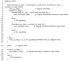
[符号化装置の変換部及び量子化部の処理]
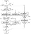
次に、以上のように構成された変換部106の処理について、量子化部108の処理とともに図12Aを参照しながら説明する。図12Aは、実施の形態1の第1態様に係る符号化装置100の変換部106及び量子化部108の処理を示すフローチャートである。[Processing of the conversion unit and quantization unit of the encoding device]
Next, the processing of the converting
変換モード判定部1061は、符号化対象ブロックで適応的変換基底選択モードが有効であるか否かを判定する(S101)。 The transformation
適応的変換基底選択モードが有効ではない場合は(S101のNO)、第1の変換基底選択部1063は、水平方向及び垂直方向の第1の変換基底として1つの基本変換基底を選択する(S102)。 If the adaptive transformation base selection mode is not valid (NO in S101), the first transformation
適応的変換基底選択モードが有効である場合は(S101のYES)、サイズ判定部1062は、水平方向の変換サイズが一定範囲を超えるか否かを判定する(S103)。つまり、サイズ判定部1062は、符号化対象ブロックの水平サイズが第1の水平閾値サイズより大きいか否かを判定する。 If the adaptive transformation base selection mode is valid (YES in S101), the
水平方向の変換サイズが一定範囲を超える場合は(S103のYES)、第1の変換基底選択部1063は、水平方向の第1の変換基底として、複数の適応的変換基底から水平方向の変換基底を選択する(S104)。 If the horizontal transformation size exceeds a certain range (YES in S103), the first transformation
水平方向の変換サイズが一定範囲以内である場合は(S103のNO)、第1の変換基底選択部1063は、水平方向の第1の変換基底として、固定の変換基底を選択する(S105)。 If the horizontal transformation size is within a certain range (NO in S103), the first transformation
次に、サイズ判定部1062は、垂直方向の変換サイズが一定範囲を超えるか否かを判定する(S106)。つまり、サイズ判定部1062は、符号化対象ブロックの垂直サイズが第1の垂直閾値サイズより大きいか否かを判定する。 Next, the
垂直方向の変換サイズが一定範囲を超える場合は(S106のYES)、第1の変換基底選択部1063は、垂直方向の第1の変換基底として、複数の適応的変換基底から垂直方向の変換基底を選択する(S107)。 If the vertical transformation size exceeds a certain range (YES in S106), the first transformation
垂直方向の変換サイズが一定範囲以内である場合は(S106のNO)、第1の変換基底選択部1063は、垂直方向の第1の変換基底として、固定の変換基底を選択する(S108)。 If the vertical transformation size is within a certain range (NO in S106), the first transformation
なお、水平方向及び垂直方向の変換基底の選択順序は、水平方向及び垂直方向の順であってもよいし、その逆順であってもよい。また、水平方向の変換基底と垂直方向の変換基底とが同時に選択されてもよい。 Note that the selection order of the horizontal and vertical conversion bases may be in the order of the horizontal and vertical directions, or may be in the reverse order. Furthermore, a horizontal transformation base and a vertical transformation base may be selected at the same time.
第1の変換部1064は、ステップS102、S107又はステップS108で選択された第1の変換基底を用いて、予測残差に対して第1の変換を実施して、第1の変換係数を生成する(S109)。 The
次に、第2の変換実施判定部1065は、第1の変換係数に対して第2の変換を実施するか否かを判定する(S110)。ここでは、第2の変換実施判定部1065は、符号化対象ブロックで適応的変換基底選択モードが有効であるか否かに基づいて、第2の変換を実施するか否かを判定する。 Next, the second conversion
適応的変換基底選択モードが有効である場合は(S110のYES)、第2の変換基底の選択と第2の変換とはいずれも実施されず、量子化部108は、第1の変換係数の量子化を実施することで量子化係数を生成する(S113)。つまり、図12AのステップS111及びステップS112がスキップされる。 If the adaptive transformation base selection mode is enabled (YES in S110), neither the selection of the second transformation base nor the second transformation is performed, and the
適応的変換基底選択モードが有効ではない場合には(S110のNO)、第2の変換基底選択部1066は、1つ又は複数の第2の変換基底の候補の中から第2の変換基底を選択する(S111)。そして、第2の変換部1067は、選択された第2の変換基底を用いて第1の変換係数に対して第2の変換を実施することで、第2の変換係数を生成する(S112)。その後、量子化部108は、第2の変換係数の量子化を実施することで量子化係数を生成する(S113)。 If the adaptive transformation base selection mode is not enabled (NO in S110), the second transformation
上記の基本変換基底としては、所定の変換基底を用いることができる。この場合、水平方向及び垂直方向の第1の変換基底が所定の変換基底であるか否かに基づいて適応的変換基底選択モードが有効であるか否かが判定されてもよい。また、その所定の変換基底は、1つの変換基底であってもよいし、2つ以上の変換基底であってもよい。 A predetermined conversion base can be used as the above basic conversion base. In this case, it may be determined whether the adaptive transformation base selection mode is valid based on whether the first transformation bases in the horizontal and vertical directions are predetermined transformation bases. Further, the predetermined conversion base may be one conversion base or may be two or more conversion bases.
また、第2の変換を実施しない(スキップする)場合には、第2の変換を実施しなくてもよいし、変換を実施しないことと等価となる変換を第2の変換として実施してもよい。前者においては、第2の変換を実施しないことを示す情報がビットストリーム内に符号化されてもよい。また、後者においては、変換を実施しないことと等価となる変換を示す情報がビットストリーム内に符号化されてもよい。以降、各変換をスキップする処理においても同様のことが言える。 In addition, if the second conversion is not performed (skip), the second conversion may not be performed, or a conversion equivalent to not performing the conversion may be performed as the second conversion. good. In the former case, information indicating not to perform the second transformation may be encoded within the bitstream. Furthermore, in the latter case, information indicating a transformation that is equivalent to not performing the transformation may be encoded within the bitstream. The same thing can be said about the process of skipping each conversion thereafter.
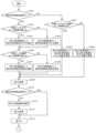
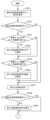
なお、図12Aに示したステップ及びステップの順序などは、一例であり、これに限定されない。例えば、図12Bのように、図12Aの適応的変換基底選択モードの判定(S101)と第2の変換の実施判定(S110)とが統合されてもよい。図12Bは、実施の形態1の第1態様に係る符号化装置100の変換部106及び量子化部108の処理の変形例を示すフローチャートである。図12Bのフローチャートは、図12Aのフローチャートと実質的に等しいフローチャートである。 Note that the steps and the order of steps shown in FIG. 12A are merely examples, and the steps are not limited thereto. For example, as shown in FIG. 12B, the adaptive transformation base selection mode determination (S101) in FIG. 12A and the second transformation implementation determination (S110) may be integrated. FIG. 12B is a flowchart illustrating a modification of the processing by the
図12Bでは、第2の変換の実施判定(S110)は削除され、第1の変換(S109)が2つに分割されている(S109A、S109B)。この場合、符号化装置100の変換部106は、第2の変換実施判定部1065を備えなくてもよい。 In FIG. 12B, the second conversion execution determination (S110) is deleted, and the first conversion (S109) is divided into two (S109A, S109B). In this case, the
逆変換部114における第2の逆変換基底の選択及び第2の逆変換、並びに、第1の逆変換基底の選択及び第1の逆変換については、図12Aの変換部106の変換に準じて実施されればよいので説明及び図示を省略する。 The selection of the second inverse transformation base and the second inverse transformation in the
なお、第1の変換は、非特許文献2に記載されているEMTのような適応的に変換基底を選択できる周波数変換であってもよいし、一定の条件で変換基底を切り替える周波数変換であってもよく、その他の一般的な変換であってもよい。例えば、第1の変換基底が選択される代わりに固定の変換基底が設定されてもよい。また、第1の変換を実施しないことと等価な第1の変換基底が使用されてもよい。また、第1の変換では、適応的変換基底選択モードと固定の基本変換基底(例えば、タイプ2の離散コサイン変換(DCT-II)の変換基底)を用いる変換基底固定モードとのどちらが有効であるかを示す識別情報を用いて、2つのモードのいずれかを選択できるようにしてもよい。この場合、識別情報によって、適応的変換基底選択モードと変換基底固定モードとのどちらが符号化対象ブロックで有効であるかを判断することもできる。例えば、非特許文献2に記載されているEMTでは、適応的変換基底選択モードが有効か否かをCU(Coding Unit)などの単位で示す識別情報(emt_cu_flag)が存在するため、その識別情報を用いて符号化対象ブロックで適応的変換基底選択モードが有効であるか否かを判定できる。 Note that the first transformation may be a frequency transformation in which a transformation base can be adaptively selected, such as EMT described in
なお、第2の変換は、非特許文献2に記載されているNSSTのような2次的な変換処理であってもよいし、一定の条件で変換基底を切り替える変換であってもよく、その他の一般的な変換であってもよい。例えば、第2の変換基底が選択される代わりに固定の変換基底が設定されてもよい。また、第2の変換を実施しないことと等価な第2の変換基底が使用されてもよい。また、NSSTは、DCT又はDST後の周波数空間変換であってもよく、例えば、オフラインで取得したDCT又はDSTの変換係数に対するKLT(Karhunen Loveve Transform)や、KLTと同等の基底を表現し、回転変換の組合せにより表現されるHyGT(Hypercube-Givens Transform)であってもよい。 Note that the second transformation may be a secondary transformation process such as NSST described in
なお、本処理は輝度信号と色差信号とのいずれにも適用でき、入力信号がRGB形式であれば、R、G、Bの各信号に対して適用してもよい。さらに、輝度信号と色差信号とでは、第1の変換あるいは第2の変換において選択可能な基底が異なっていてもよい。例えば、輝度信号は色差信号に比べて周波数帯域が広いため、最適な変換を行うために、輝度信号の第1の変換あるいは第2の変換では、色差よりも多くの種類の基底が選択候補として用いられてもよい。また、本処理はイントラ処理とインター処理とのいずれにおいても適用できる。 Note that this processing can be applied to both luminance signals and color difference signals, and if the input signal is in RGB format, it may be applied to each of R, G, and B signals. Furthermore, the bases that can be selected in the first conversion or the second conversion may be different between the luminance signal and the color difference signal. For example, since the luminance signal has a wider frequency band than the chrominance signal, in order to perform the optimal conversion, more types of bases are selected as selection candidates than the chrominance signal in the first or second transformation of the luminance signal. may be used. Further, this processing can be applied to both intra processing and inter processing.
[効果等]
非特許文献2に記載の第1の変換(一次変換)及び第2の変換(二次変換)では、最適な変換基底又は変換係数(フィルタ)が選択され、トータルで最適な符号化効率が実現される。したがって、第1の変換及び第2の変換に用いられる変換基底及び変換係数(フィルタ)の候補の最適な組み合わせを探索するために第1の変換及び第2の変換を多数回試行する必要がある。すなわち、非特許文献2に記載の変換方法では、第1の変換の変換基底の候補と第2の変換の変換基底の候補との組み合わせの全てについて評価値を計算し、評価値が最小となる組み合わせを選択する必要がある。そのため、非特許文献2に記載の変換方法では、処理量が膨大になるという課題を本発明者らは見出した。[Effects etc.]
In the first transformation (linear transformation) and second transformation (secondary transformation) described in
そこで、本態様に係る符号化装置100は、第1の変換と第2の変換との両方を常に行うのではなく、適応的変換基底選択モードが有効であるか否かに基づいて第2の変換をスキップする。これにより、符号化装置100は、第1の変換の変換基底の候補と第2の変換の変換基底の候補との組み合わせの数を削減することができ、処理量を低減することができる。 Therefore, the
また、本態様に係る符号化装置100によれば、水平方向及び垂直方向の変換サイズの条件に基づいて、第1の変換基底の候補を限定することができる。これにより、最良の第1の変換基底を試行によって探索する処理量を低減することが可能となる。また、第1の変換基底に選択した基底などの条件に基づいて、最良の第2の変換基底を試行によって探索する処理を低減することが可能となる。さらに、第1の変換と第2の変換との組み合わせの試行に係る処理量を低減することが可能となる。 Further, according to the
一例として、基本変換基底として、DCT-IIの変換基底を用いることができる。DCT-IIは、残差形状が平坦もしくはランダムになると採用される可能性が高く、例えば第1の変換基底としてDCT-IIを使用すると、低域への集約度が高まる傾向があるため第2の変換の効果が高くなる可能性がある。一方、DCT-II以外の変換基底では高域成分が残りやすく、第2の変換の効果が低下する可能性がある。 As an example, a DCT-II transformation base can be used as the basic transformation base. DCT-II is likely to be adopted when the residual shape is flat or random. For example, if DCT-II is used as the first transformation base, the degree of aggregation in the low range tends to increase, so the second The conversion effect may be increased. On the other hand, in transform bases other than DCT-II, high-frequency components tend to remain, which may reduce the effect of the second transform.
また、一例として、変換サイズが一定範囲内であった場合に選択される固定変換基底として、DST-VIIの変換基底を用いることができる。DST-VIIは、特にイントラ処理であれば、残差形状が傾斜かつサイズが小さい場合に、非常に高い確率で選択される傾向がある。 Furthermore, as an example, a DST-VII transformation base can be used as a fixed transformation base that is selected when the transformation size is within a certain range. DST-VII tends to be selected with a very high probability, especially in intra processing, when the residual shape is sloped and small in size.
なお、基本変換基底としては、1つの所定の変換基底に限るものではなく、複数の所定の変換基底が用いられてもよい。 Note that the basic conversion base is not limited to one predetermined conversion base, and a plurality of predetermined conversion bases may be used.
また、第2の変換基底の選択と第2の変換とを実施するかどうかは、変換サイズに応じて切替えられてもよい。また、第2の変換基底の候補は、変換サイズに応じて切り替えられてもよい。 Furthermore, whether or not to select the second transformation base and perform the second transformation may be switched depending on the transformation size. Further, candidates for the second transformation base may be switched depending on the transformation size.
また、適応的変換基底選択モードが有効であるかどうかに基づいて第2の変換を実施するかどうかを切替えるのみとし、変換サイズに応じた第1の変換基底の切替えは行わない構成としてもよい。つまり、図12Aにおいて、ステップS103、S105、S106及びステップS108が削除されてもよい。ここで、適応的変換基底選択モードが有効であるかどうかは、当該モードの使用を示す識別情報、あるいは、第1の変換基底のタイプに基づいて判定してもよい。 Alternatively, it may be configured such that whether or not to perform the second transformation is only switched based on whether the adaptive transformation base selection mode is enabled, and the first transformation base is not switched according to the transformation size. . That is, in FIG. 12A, steps S103, S105, S106, and step S108 may be deleted. Here, whether the adaptive transformation base selection mode is effective may be determined based on identification information indicating the use of the mode or the type of the first transformation base.
同様に、適応的変換基底選択モードが有効であるかどうかに基づく第2の変換の実施有無の切替えは行わずに、変換サイズに応じた第1の変換基底の切替えのみを行う構成としてもよい。つまり、図12Aにおいて、ステップS110が削除されてもよい。 Similarly, a configuration may be adopted in which only the first transformation base is switched according to the transformation size, without switching whether or not to perform the second transformation based on whether or not the adaptive transformation base selection mode is enabled. . That is, step S110 may be deleted in FIG. 12A.
なお、適応的変換基底選択モードが有効であるか否かによらず、第2の変換基底の選択及び第2の変換をスキップしないようにしてもよい。また、第1の変換基底の選択方法によらず、適応的変換基底選択モードが有効ではない場合に、第2の変換基底の選択及び第2の変換を実施し、適応的変換基底選択モードが有効である場合に、第2の変換基底の選択及び第2の変換をスキップするようにしてもよい。 Note that the selection of the second transformation base and the second transformation may not be skipped regardless of whether the adaptive transformation base selection mode is enabled or not. In addition, regardless of the first transformation base selection method, when the adaptive transformation base selection mode is not effective, the second transformation base selection and the second transformation are performed, and the adaptive transformation base selection mode If valid, the selection of the second transformation base and the second transformation may be skipped.
また、第1の変換基底として複数の適応的変換基底から候補を選択するか、固定変換基底を選択するかの水平方向又は垂直方向の具体的な変換サイズの閾値(つまり、第1の水平閾値サイズ及び第1の垂直閾値サイズ)としては、4、8、16、32又は64画素などが用いられてもよい。 In addition, a specific transformation size threshold in the horizontal or vertical direction (that is, a first
[他の態様との組み合わせ]
本態様を本開示における他の態様の少なくとも一部と組み合わせて実施してもよい。また、本態様のフローチャートに記載の一部の処理、装置の一部の構成、シンタックスの一部などを他の態様と組み合わせて実施してもよい。[Combination with other aspects]
This aspect may be implemented in combination with at least some of the other aspects of this disclosure. Furthermore, some of the processes, some of the configurations of the apparatus, some of the syntax, etc. described in the flowchart of this embodiment may be implemented in combination with other embodiments.
(実施の形態1の第2態様)
次に、実施の形態1の第2態様について説明する。本態様では、第1態様における第1の変換及び第2の変換に関する各種信号の符号化の一例について説明する。以下に、第1態様と異なる点を中心に、本態様について図面を参照しながら具体的に説明する。(Second aspect of Embodiment 1)
Next, a second aspect of the first embodiment will be explained. In this aspect, an example of encoding of various signals related to the first conversion and the second conversion in the first aspect will be described. This aspect will be specifically described below with reference to the drawings, focusing on the points that are different from the first aspect.
なお、本態様に係る符号化装置100の変換部106及び逆変換部114の内部構成は、第1態様と同様であるので図示を省略する。 Note that the internal configurations of the
[符号化装置の変換部、量子化部及びエントロピー符号化部の処理]
本態様に係る符号化装置100の変換部106、量子化部108及びエントロピー符号化部110の処理について、図13A及び図13Bを参照しながら説明する。図13Aは、実施の形態1の第2態様に係る符号化装置100の変換部106及び量子化部108の処理を示すフローチャートである。図13Bは、実施の形態1の第2態様に係る符号化装置100のエントロピー符号化部110の処理を示すフローチャートである。図13A及び図13Bでは、第1態様と共通する処理については、同一の符号を付して説明を省略する。[Processing of the conversion unit, quantization unit, and entropy encoding unit of the encoding device]
Processing by the
量子化の実施後に(S113)、エントロピー符号化部110は、適応的変換基底選択モード信号を符号化する(S201)。適応的変換基底選択モード信号は、適応的変換基底選択モードの識別情報の一例である。 After performing quantization (S113), the
そして、適応的変換基底選択モードが有効であれば(S202のYES)、水平方向の変換サイズが一定範囲を超える場合に(S203のYES)、エントロピー符号化部110は、水平方向の第1の基底選択信号を符号化する(S204)。一方、水平方向の変換サイズが一定範囲以内である場合には(S203のNO)、エントロピー符号化部110は、水平方向の第1の基底選択信号を符号化しない。さらに、垂直方向の変換サイズが一定範囲を超える場合は(S205のYES)、エントロピー符号化部110は、垂直方向の第1の基底選択信号を符号化する(S206)。一方、垂直方向の変換サイズが一定範囲以内である場合には(S205のNO)、エントロピー符号化部110は、垂直方向の第1の基底選択信号を符号化しない。 Then, if the adaptive transform base selection mode is enabled (YES in S202), and if the horizontal transform size exceeds a certain range (YES in S203), the
適応的変換基底選択モードが有効ではない場合は(S202のNO)、第1の基底選択信号の符号化(S204、S206)がスキップされる。 If the adaptive transform basis selection mode is not enabled (NO in S202), encoding of the first basis selection signal (S204, S206) is skipped.
次に、エントロピー符号化部110は、量子化係数を符号化する(S207)。 Next, the
ここで、適応的変換基底選択モードが有効ではない場合は(S208のNO)、エントロピー符号化部110は、第2の基底選択信号を符号化する(S209)。一方、適応的変換基底選択モードが有効である場合は(S208のYES)、第2の基底選択信号の符号化(S209)はスキップされる。 Here, if the adaptive transformation base selection mode is not valid (NO in S208), the
なお、それぞれの符号化の順序を予め定めておき、上記の符号化の順序とは異なるように各種信号を符号化してもよい。 Note that the respective encoding orders may be determined in advance, and various signals may be encoded in a manner different from the above-mentioned encoding order.
第2の変換を実施しない(スキップする)場合に、第2の変換を実施しないことを示す信号が符号化されてもよいし、変換しないことと等価な第2の基底を選択する信号が符号化されてもよい。 When not performing (skipping) the second transform, a signal indicating not to perform the second transform may be encoded, or a signal selecting a second base equivalent to not performing the transform may be encoded. may be converted into
[シンタックス]
ここで、本態様におけるシンタックスについて説明する。図14は、実施の形態1の第2態様におけるシンタックスの具体例を示す。[Syntax]
Here, the syntax in this aspect will be explained. FIG. 14 shows a specific example of syntax in the second aspect of the first embodiment.
図14では、例えば、適応的変換基底選択モード信号(emt_cu_flag)がセットされている場合に(4行目)、水平方向の変換サイズ(horizontal_tu_size)が第1の水平閾値サイズ(horizontal_tu_size_th)より大きければ(5行目)、水平方向の第1の基底選択信号(emt_horizontal_tridx)が符号化される(6行目)。また、垂直方向の変換サイズ(vertical_tu_size)が第1の垂直閾値サイズ(vertical_tu_size_th)より大きければ(11行目)、垂直方向の第1の基底選択信号(emt_vertical_tridx)が符号化される(12行目)。それ以外の条件では(8行目及び14行目)、第1の基底選択信号の符号化がスキップされる(9行目及び15行目)。 In FIG. 14, for example, when the adaptive transformation base selection mode signal (emt_cu_flag) is set (line 4), if the horizontal transformation size (horizontal_tu_size) is larger than the first horizontal threshold size (horizontal_tu_size_th), (line 5), and the first base selection signal in the horizontal direction (emt_horizontal_tridx) is encoded (line 6). Furthermore, if the vertical transform size (vertical_tu_size) is larger than the first vertical threshold size (vertical_tu_size_th) (line 11), the first base selection signal (emt_vertical_tridx) in the vertical direction is encoded (line 12). ). Under other conditions (
また、適応的変換基底選択モード信号(emt_cu_flag)がセットされていない場合は(19行目)、第2の基底選択信号(secondary_tridx)が符号化される(20行目)。逆に、適応的変換基底選択モード信号(emt_cu_flag)がセットされている場合は(22行目)、第2の基底選択信号(secondary_tridx)の符号化がスキップされる(23行目)。 Furthermore, if the adaptive transformation basis selection mode signal (emt_cu_flag) is not set (line 19), the second basis selection signal (secondary_tridx) is encoded (line 20). Conversely, when the adaptive transform basis selection mode signal (emt_cu_flag) is set (line 22), encoding of the second basis selection signal (secondary_tridx) is skipped (line 23).
[変換基底及び符号化信号の具体例]
次に、変換基底及び符号化信号の具体例にについて説明する。図15は、実施の形態1の第2態様において用いられる変換基底と信号の符号化の有無との具体例を示す。[Specific examples of conversion bases and encoded signals]
Next, specific examples of the transform base and encoded signal will be explained. FIG. 15 shows a specific example of the transformation base used in the second aspect of the first embodiment and the presence or absence of signal encoding.
図15では、適応的変換基底選択モードが有効ではない場合に、符号化ブロックのサイズに関わらず、DCT-IIの変換基底が水平方向及び垂直方向の第1の変換基底として用いられる。つまり、基本変換基底として、DCT-IIの変換基底が用いられる。また、第2の変換が実施されるとともに(ON)、当該第2の変換で用いられた第2の変換基底を示す第2の基底選択信号(secondary_tridx)がビットストリーム内に符号化される。 In FIG. 15, when the adaptive transform base selection mode is not enabled, the transform base of DCT-II is used as the first transform base in the horizontal and vertical directions, regardless of the size of the coding block. That is, the DCT-II transformation base is used as the basic transformation base. Furthermore, when the second transformation is performed (ON), a second base selection signal (secondary_tridx) indicating the second transformation base used in the second transformation is encoded into the bitstream.
一方、適応的変換基底選択モードが有効である場合には、符号化対象ブロックの水平サイズH及び垂直サイズVに応じて、DST-VIIの変換基底及び他の変換基底の組み合わせ(index0~index3)が水平方向及び垂直方向の第1の変換基底の候補として用いられる。また、符号化対象ブロックのサイズに関わらず、第2の変換は実施されない(OFF)。また、第2の基底選択信号(secondary_tridx)も符号化されないが、適応的変換基底選択モード信号(emt_cu_flag)がビットストリーム内に符号化される。さらに、符号化対象ブロックの水平サイズHが4画素より大きい場合に、水平方向の第1の基底選択信号(emt_horizontal_tridx)がビットストリーム内に符号化される。また、符号化対象ブロックの垂直サイズVが4画素より大きい場合に、垂直方向の第1の基底選択信号(emt_vertical_tridx)がビットストリーム内に符号化される。 On the other hand, when the adaptive transform base selection mode is enabled, a combination of the DST-VII transform base and other transform bases (index0 to index3) is selected depending on the horizontal size H and vertical size V of the block to be encoded. are used as candidates for the first transformation base in the horizontal and vertical directions. Furthermore, the second transformation is not performed (OFF) regardless of the size of the block to be encoded. The second basis selection signal (secondary_tridx) is also not encoded, but the adaptive transform basis selection mode signal (emt_cu_flag) is encoded in the bitstream. Furthermore, when the horizontal size H of the encoding target block is larger than 4 pixels, the first horizontal base selection signal (emt_horizontal_tridx) is encoded into the bitstream. Further, when the vertical size V of the encoding target block is larger than 4 pixels, the first base selection signal in the vertical direction (emt_vertical_tridx) is encoded in the bitstream.
例えば、水平サイズHが4画素以下であり、かつ、垂直サイズVが4画素以下である場合には、DST-VIIの変換基底のみが水平方向及び垂直方向の第1の変換基底の候補として用いられる。このとき、水平方向及び垂直方向の第1の基底選択信号(emt_horizontal_tridx及びemt_vertical_tridx)は符号化されない。 For example, if the horizontal size H is 4 pixels or less and the vertical size V is 4 pixels or less, only the DST-VII transformation base is used as a candidate for the first transformation base in the horizontal and vertical directions. It will be done. At this time, the first base selection signals in the horizontal and vertical directions (emt_horizontal_tridx and emt_vertical_tridx) are not encoded.
また例えば、水平サイズHが4画素以下であり、かつ、垂直サイズVが4画素より大きい場合には、DST-VIIの変換基底のみが水平方向の第1の変換基底の候補として用いられ、DST-VIIの変換基底及び他の変換基底が垂直方向の第1の変換基底の候補として用いられる。このとき、水平方向の第1の基底選択信号(emt_horizontal_tridx)は符号化されないが、垂直方向の第1の基底選択信号(emt_vertical_tridx)は符号化される。 For example, if the horizontal size H is 4 pixels or less and the vertical size V is larger than 4 pixels, only the DST-VII conversion base is used as a candidate for the first horizontal conversion base, and the DST - The transformation base of VII and other transformation bases are used as candidates for the first transformation base in the vertical direction. At this time, the first base selection signal in the horizontal direction (emt_horizontal_tridx) is not encoded, but the first base selection signal in the vertical direction (emt_vertical_tridx) is encoded.
また例えば、水平サイズHが4画素より大きく、かつ、垂直サイズVが4画素以下である場合には、DST-VIIの変換基底及び他の変換基底が水平方向の第1の変換基底の候補として用いられ、DST-VIIの変換基底のみが垂直方向の第1の変換基底の候補として用いられる。このとき、水平方向の第1の基底選択信号(emt_horizontal_tridx)は符号化されるが、垂直方向の第1の基底選択信号(emt_vertical_tridx)は符号化されない。 For example, if the horizontal size H is larger than 4 pixels and the vertical size V is 4 pixels or less, the DST-VII conversion base and other conversion bases are used as candidates for the first horizontal conversion base. and only the DST-VII transformation basis is used as a candidate for the first transformation basis in the vertical direction. At this time, the first base selection signal in the horizontal direction (emt_horizontal_tridx) is encoded, but the first base selection signal in the vertical direction (emt_vertical_tridx) is not encoded.
また例えば、水平サイズHが4画素より大きく、かつ、垂直サイズVが4画素より大きい場合には、DST-VIIの変換基底及び他の変換基底が水平方向及び垂直方向の各々の第1の変換基底の候補として用いられる。このとき、水平方向及び垂直方向の第1の基底選択信号(emt_horizontal_tridx及びemt_vertical_tridx)は符号化される。 Further, for example, if the horizontal size H is larger than 4 pixels and the vertical size V is larger than 4 pixels, the conversion base of DST-VII and the other conversion bases are the first conversion in the horizontal direction and the vertical direction. Used as a candidate basis. At this time, the first base selection signals in the horizontal and vertical directions (emt_horizontal_tridx and emt_vertical_tridx) are encoded.
[効果等]
以上のように、本態様に係る符号化装置100によれば、適応的変換基底選択モードが有効であり、かつ変換サイズが一定範囲を超える場合にのみ、第1の変換基底を示す情報(第1の基底選択信号)を符号化することができ、第1の変換基底のシグナリングに必要な符号量を削減できる可能性がある。また、適応的変換基底選択モードが有効ではない場合にのみ、第2の変換基底を示す情報(第2の基底選択信号)を符号化することができ、第2の変換基底のシグナリングに必要な符号量を削減できる可能性がある。また、第2の変換をスキップするかどうかを判定するための情報(適応的変換基底選択モード信号など)を、第2の変換基底を示す情報よりも前に符号化することで、第2の変換基底を示す情報が符号化されているかどうかを復号時に判断することができる。[Effects etc.]
As described above, according to the
なお、適応的変換基底選択モードによらず、第2の基底選択信号の符号化を常に実施するようにしてもよい。また、変換サイズによらず、適応的変換基底選択モードであれば第1の基底選択信号の符号化を常に実施するようにしてもよい。また、第1の基底選択信号の符号化の有無を、水平方向のサイズと垂直方向のサイズとで独立して判断してもよいし、組み合わせて判断してもよい。 Note that the second basis selection signal may be always encoded regardless of the adaptive transformation basis selection mode. Furthermore, regardless of the transform size, the first base selection signal may always be encoded in the adaptive transform base selection mode. Further, whether or not the first base selection signal is encoded may be determined based on the horizontal size and the vertical size independently, or may be determined in combination.
[他の態様との組み合わせ]
本態様を本開示における他の態様の少なくとも一部と組み合わせて実施してもよい。また、本態様のフローチャートに記載の一部の処理、装置の一部の構成、シンタックスの一部などを他の態様と組み合わせて実施してもよい。[Combination with other aspects]
This aspect may be implemented in combination with at least some of the other aspects of this disclosure. Furthermore, some of the processes, some of the configurations of the apparatus, some of the syntax, etc. described in the flowchart of this embodiment may be implemented in combination with other embodiments.
(実施の形態1の第3態様)
次に、実施の形態1の第3態様について説明する。本態様では、適応的変換基底選択モードが有効ではない場合に、符号化対象ブロックのサイズに応じて異なる基本変換基底が第1の変換基底として用いられる点が上記第1態様と異なる。以下に、第1態様及び第2態様と異なる点を中心に、本態様について図面を参照しながら具体的に説明する。(Third aspect of Embodiment 1)
Next, a third aspect of the first embodiment will be explained. This aspect differs from the first aspect in that when the adaptive transformation base selection mode is not enabled, a different basic transformation base is used as the first transformation base depending on the size of the block to be encoded. This aspect will be specifically described below with reference to the drawings, focusing on the points that are different from the first aspect and the second aspect.
なお、本態様に係る符号化装置100の変換部106及び逆変換部114の内部構成は、第1態様と同様であるので図示を省略する。 Note that the internal configurations of the
[符号化装置の変換部及び量子化部の処理]
本態様に係る符号化装置100の変換部106及び量子化部108の処理について、図16を参照しながら説明する。図16は、実施の形態1の第3態様に係る符号化装置100の変換部106及び量子化部108の処理を示すフローチャートである。図16では、第1態様と共通する処理については、同一の符号を付して説明を省略する。[Processing of the conversion unit and quantization unit of the encoding device]
Processing by the
適応的変換基底選択モードが有効ではない場合は(S101のNO)、サイズ判定部1062は、変換サイズが一定範囲以内であるか否かを判定する(S301)。つまり、サイズ判定部1062は、符号化対象ブロックのサイズが第2の閾値サイズ以下であるか否かを判定する。例えば、サイズ判定部1062は、符号化対象ブロックの水平サイズと垂直サイズとの積が閾値以下であるか否かを判定することにより、符号化対象ブロックのサイズが第2の閾値サイズ以下であるか否かを判定する。 If the adaptive transformation base selection mode is not valid (NO in S101), the
ここで、変換サイズが一定範囲以内である場合(S301のYES)、第1の変換基底選択部1063は、水平方向及び垂直方向の第1の変換基底として第2基本変換基底を選択する(S302)。一方、変換サイズが一定範囲を超える場合は(S301のNO)、第1の変換基底選択部1063は、水平方向及び垂直方向の第1の変換基底として第1基本変換基底を選択する(S303)。 Here, if the transformation size is within a certain range (YES in S301), the first transformation
一例として、第1基本変換基底として、DCT-IIの変換基底を用いることができ、第2基本変換基底として、DST-VIIの変換基底を用いることができる。 As an example, a DCT-II transformation base can be used as the first basic transformation base, and a DST-VII transformation base can be used as the second basic transformation base.
なお、基本変換基底は、複数の基本変換基底の候補の中から選択されてもよい。 Note that the basic transformation base may be selected from a plurality of candidates for basic transformation bases.
なお、適応的変換基底選択モードが有効であるか否かによらず、第2の変換基底の選択及び第2の変換をスキップしないようにしてもよい。また、第1の変換基底の選択方法によらず、適応的変換基底選択モードが有効ではない場合に、第2の変換基底の選択及び第2の変換を実施し、適応的変換基底選択モードが有効である場合に、第2の変換基底の選択及び第2の変換をスキップするようにしてもよい。 Note that the selection of the second transformation base and the second transformation may not be skipped regardless of whether the adaptive transformation base selection mode is enabled or not. In addition, regardless of the first transformation base selection method, when the adaptive transformation base selection mode is not effective, the second transformation base selection and the second transformation are performed, and the adaptive transformation base selection mode If valid, the selection of the second transformation base and the second transformation may be skipped.
また、適応的変換基底選択モードが有効ではない場合に、第1基本変換基底及び第2基本変換基底の一方を選択するための第2の閾値サイズとしては、例えば4x4、4x8、8x4、8x8画素サイズなどを用いることができる。また、閾値と比較される変換サイズとしては、本態様のように符号化対象ブロックの水平サイズと垂直サイズとの積を用いてもよいし、水平サイズ及び垂直サイズのそれぞれを用いてもよい。 Further, when the adaptive transformation base selection mode is not enabled, the second threshold size for selecting one of the first basic transformation base and the second basic transformation base is, for example, 4x4, 4x8, 8x4, 8x8 pixels. Size, etc. can be used. Furthermore, as the transform size to be compared with the threshold, the product of the horizontal size and vertical size of the block to be encoded may be used as in this embodiment, or each of the horizontal size and vertical size may be used.
なお、適応的変換基底選択モードが有効ではない場合は、水平サイズ及び垂直サイズの積が一定範囲以内ならば、水平方向及び垂直方向の第1の変換基底として第2基本変換基底を選択し、第2の変換基底の選択及び第2の変換がスキップされてもよい。 Note that if the adaptive transformation base selection mode is not enabled, if the product of the horizontal size and vertical size is within a certain range, the second basic transformation base is selected as the first transformation base in the horizontal and vertical directions, The selection of the second transformation basis and the second transformation may be skipped.
[効果等]
以上のように、本態様に係る符号化装置100によれば、適応的変換基底選択モードが有効ではない場合に、変換サイズに応じて第1の変換基底を第1基本変換基底と第2基本変換基底との間で切り替えることができる。したがって、変換サイズに対応する第1の変換基底を用いて第1の変換を行うことができ、符号量の削減を図ることができる。[Effects etc.]
As described above, according to the
[他の態様との組み合わせ]
本態様を本開示における他の態様の少なくとも一部と組み合わせて実施してもよい。また、本態様のフローチャートに記載の一部の処理、装置の一部の構成、シンタックスの一部などを他の態様と組み合わせて実施してもよい。[Combination with other aspects]
This aspect may be implemented in combination with at least some of the other aspects of this disclosure. Furthermore, some of the processes, some of the configurations of the apparatus, some of the syntax, etc. described in the flowchart of this embodiment may be implemented in combination with other embodiments.
(実施の形態1の第4態様)
次に、実施の形態1の第4態様について説明する。本態様では、第3態様に係る第1の変換及び第2の変換に関する各種信号の符号化の一例について説明する。以下に、第1~第3態様と異なる点を中心に、本態様について図面を参照しながら具体的に説明する。(Fourth aspect of Embodiment 1)
Next, a fourth aspect of the first embodiment will be described. In this aspect, an example of encoding various signals related to the first conversion and the second conversion according to the third aspect will be described. This aspect will be specifically explained below with reference to the drawings, focusing on the points that are different from the first to third aspects.
なお、本態様に係る符号化装置100の変換部106及び逆変換部114の内部構成は、第1態様と同様であるので図示を省略する。 Note that the internal configurations of the
[符号化装置の変換部、量子化部及びエントロピー符号化部の処理]
本態様に係る符号化装置100の変換部106、量子化部108及びエントロピー符号化部110の処理について、図17A及び図17Bを参照しながら説明する。図17Aは、実施の形態1の第4態様に係る符号化装置100の変換部106及び量子化部108の処理を示すフローチャートである。図17Bは、実施の形態1の第4態様に係る符号化装置100のエントロピー符号化部110の処理を示すフローチャートである。図17A及び図17Bでは、第1~第3態様のいずれかと共通する処理については、同一の符号を付して説明を省略する。[Processing of the conversion unit, quantization unit, and entropy encoding unit of the encoding device]
Processing by the
量子化の実施後に(S113)、エントロピー符号化部110は、適応的変換基底選択モード信号の符号化をスキップするか否かを判定する(S401)。例えば、エントロピー符号化部110は、以下の(A)及び(B)のいずれかの条件が満たされる場合に、適応的変換基底選択モード信号の符号化をスキップすると判定し、そうでない場合に、適応的変換基底選択モード信号の符号化をスキップしないと判定する。 After performing quantization (S113), the
(A)適応的変換基底選択モードが有効ではない。 (A) Adaptive transformation basis selection mode is not enabled.
(B)適応的変換基底選択モードが有効であり、かつ、以下の(B1)~(B4)の条件の全てが満たされる。 (B) The adaptive transformation base selection mode is valid, and all of the following conditions (B1) to (B4) are satisfied.
(B1)変換サイズが、ステップS301で用いられる第2の閾値サイズW1xH1以下である。 (B1) The conversion size is less than or equal to the second threshold size W1xH1 used in step S301.
(B2)水平方向の変換サイズが、ステップS103で用いられる第1の水平閾値サイズW2以下である。 (B2) The horizontal conversion size is less than or equal to the first horizontal threshold size W2 used in step S103.
(B3)垂直方向の変換サイズが、ステップS106で用いられる第1の垂直閾値サイズH2以下である。 (B3) The vertical conversion size is less than or equal to the first vertical threshold size H2 used in step S106.
(B4)第2基本変換基底と、水平方向及び垂直方向の固定変換基底とが、同一の変換基底である。 (B4) The second basic transformation base and the fixed transformation bases in the horizontal and vertical directions are the same transformation base.
具体例として、第2の閾値サイズW1xH1が4x4画素であり、第1の水平閾値サイズW2が4画素であり、第1の垂直閾値サイズH2が4画素であり、第2基本変換基底及び固定変換基底がともにDST-VIIの変換基底である場合に、変換サイズが4x4画素以下であれば、エントロピー符号化部110は、適応的変換基底選択モード信号の符号化をスキップすると判定する。 As a specific example, the second threshold size W1xH1 is 4x4 pixels, the first horizontal threshold size W2 is 4 pixels, the first vertical threshold size H2 is 4 pixels, and the second basic transformation base and fixed transformation If the bases are both DST-VII transform bases and the transform size is 4x4 pixels or less, the
逆に、上記の(A)及び(B)のどちらの条件も満たされない場合は、エントロピー符号化部110は、適応的変換基底選択モード信号の符号化をスキップしないと判定する。 Conversely, if neither of the above conditions (A) and (B) is satisfied,
ここで、適応的変換基底選択モード信号の符号化をスキップすると判定された場合(S401のYES)、エントロピー符号化部110は、ステップS201~ステップS206をスキップして、量子化係数を符号化する(S207)。一方、適応的変換基底選択モード信号の符号化をスキップしないと判定された場合(S401のNO)、エントロピー符号化部110は、第2態様と同様に、ステップS201~ステップS206を実行してから、量子化係数を符号化する(S207)。 Here, if it is determined to skip the encoding of the adaptive transform basis selection mode signal (YES in S401), the
なお、それぞれの符号化の順序を予め定めておき、上記の符号化の順序とは異なるように各種信号を符号化してもよい。 Note that the respective encoding orders may be determined in advance, and various signals may be encoded in a manner different from the above-mentioned encoding order.
[シンタックス]
ここで、本態様におけるシンタックスについて説明する。図18は、実施の形態1の第4態様におけるシンタックスの具体例を示す。[Syntax]
Here, the syntax in this aspect will be explained. FIG. 18 shows a specific example of syntax in the fourth aspect of the first embodiment.
図18では、例えば、適応的変換基底選択モード信号の符号化をスキップする場合は(20行目)、適応的変換基底選択モード信号(emt_cu_flag)及び第1の基底選択信号(emt_horizontal_tridx及びemt_vertical_tridx)の符号化をスキップする(21行目)。ここでは、水平方向の変換サイズ(horizontal_tu_size)が第1の水平閾値サイズ(horizontal_tu_size_th)以下であり、かつ垂直方向の変換サイズ(vertical_tu_size)が第1の垂直閾値サイズ(vertical_tu_size_th)以下である場合に、適応的変換基底選択モード信号の符号化がスキップされる。適応的変換基底選択モード信号の符号化をスキップしない場合は(3~4行目)、適応的変換基底選択モード信号(emt_cu_flag)が符号化され(5行目)、第2態様と同様に第1の基底選択信号(emt_horizontal_tridx及びemt_vertical_tridx)が必要に応じて符号化される(7~16行目)。 In FIG. 18, for example, when skipping the encoding of the adaptive transform base selection mode signal (line 20), the adaptive transform base selection mode signal (emt_cu_flag) and the first base selection signals (emt_horizontal_tridx and emt_vertical_tridx) are Skip encoding (line 21). Here, the horizontal transformation size (horizontal_tu_size) is less than or equal to the first horizontal threshold size (horizontal_tu_size_th), and the vertical transformation size (vertical_tu_size) is less than or equal to the first vertical threshold size (vertical_tu_size). ze_th) or less, Encoding of the adaptive transform basis selection mode signal is skipped. If the encoding of the adaptive transformation base selection mode signal is not skipped (
なお、適応的変換基底選択モード信号の符号化がスキップされる場合は、第2の変換基底の選択及び第2の変換がスキップされてもよい。 Note that when the encoding of the adaptive transform base selection mode signal is skipped, the selection of the second transform base and the second transform may be skipped.
[変換基底及び符号化信号の具体例]
次に、変換基底及び符号化信号の具体例にについて説明する。図19は、実施の形態1の第4態様において用いられる変換基底と信号の符号化の有無との具体例を示す。図19では、符号化対象ブロックの水平サイズ及び垂直サイズがともに4画素以下である場合の変換基底及び符号化の有無が図15と異なる。図15と異なる点を中心に図19について説明する。[Specific examples of conversion bases and encoded signals]
Next, specific examples of the transform base and encoded signal will be explained. FIG. 19 shows a specific example of the transformation base used in the fourth aspect of the first embodiment and the presence or absence of signal encoding. 19 differs from FIG. 15 in the conversion base and presence or absence of encoding when the horizontal size and vertical size of the block to be encoded are both 4 pixels or less. FIG. 19 will be described focusing on the differences from FIG. 15.
図19では、適応的変換基底選択モードが有効ではない場合に、符号化対象ブロックの水平サイズH及び垂直サイズVがともに4画素以下であれば、DCT-IIの変換基底ではなく、DST-VIIの変換基底が水平方向及び垂直方向の第1の変換基底として用いられる。 In FIG. 19, when the adaptive transform base selection mode is not enabled, if the horizontal size H and vertical size V of the block to be encoded are both 4 pixels or less, the DST-VII transform base is used instead of the DCT-II transform base. The transformation base is used as the first transformation base in the horizontal and vertical directions.
また、適応的変換基底選択モードが有効である場合に、符号化対象ブロックの水平サイズH及び垂直サイズVがともに4画素以下であれば、適応的変換基底選択モード信号(emt_cu_flag)が符号化されない。 Furthermore, when the adaptive transformation base selection mode is enabled, if the horizontal size H and vertical size V of the block to be encoded are both 4 pixels or less, the adaptive transformation base selection mode signal (emt_cu_flag) is not encoded. .
[効果等]
以上のように、本態様に係る符号化装置100によれば、適応的変換基底選択モード信号の符号化をスキップする条件を満たす場合は、適応的変換基底選択モード信号及び第1の基底選択信号の全ての符号化を省略することができ、符号量を削減できる可能性がある。[Effects etc.]
As described above, according to the
[他の態様との組み合わせ]
本態様を本開示における他の態様の少なくとも一部と組み合わせて実施してもよい。また、本態様のフローチャートに記載の一部の処理、装置の一部の構成、シンタックスの一部などを他の態様と組み合わせて実施してもよい。[Combination with other aspects]
This aspect may be implemented in combination with at least some of the other aspects of this disclosure. Furthermore, some of the processes, some of the configurations of the apparatus, some of the syntax, etc. described in the flowchart of this embodiment may be implemented in combination with other embodiments.
(実施の形態1の第5態様)
次に、実施の形態1の第5態様について説明する。本態様では、復号装置について説明する。なお、本態様に係る復号装置は、上記第1態様に係る符号化装置に対応する。つまり、本態様に係る復号装置は、上記第1態様に係る符号化装置によって符号化されたビットストリームを復号可能である。以下に、本態様について図面を参照しながら具体的に説明する。(Fifth aspect of Embodiment 1)
Next, the fifth aspect of the first embodiment will be explained. In this aspect, a decoding device will be described. Note that the decoding device according to this aspect corresponds to the encoding device according to the first aspect. That is, the decoding device according to this aspect can decode the bitstream encoded by the encoding device according to the first aspect. This aspect will be specifically described below with reference to the drawings.
[復号装置の変換部及び逆変換部の内部構成]
まず、本態様に係る復号装置200の逆変換部206の内部構成について説明する。図20は、実施の形態1の第5態様に係る復号装置200の逆変換部206の内部構成を示すブロック図である。[Internal configuration of the conversion unit and inverse conversion unit of the decoding device]
First, the internal configuration of the
図20に示すように、本態様に係る逆変換部206は、第2の逆変換実施判定部2061と、第2の逆変換基底選択部2062と、第2の逆変換部2063と、変換モード判定部2064と、サイズ判定部2065と、第1の逆変換基底選択部2066と、第1の逆変換部2067と、を備える。 As shown in FIG. 20, the
第2の逆変換実施判定部2061は、復号対象ブロックで適応的変換基底選択モードが有効であるか否かに基づいて、逆量子化部204から出力された復号対象ブロックの逆量子化係数に第2の逆変換を実施するか否かを判定する。具体的には、第2の逆変換実施判定部2061は、適応的変換基底選択モードが有効ではない場合に第2の逆変換を実施し、適応的変換基底選択モードが有効である場合に第2の逆変換を実施しないと判定する。 The second inverse transform
第2の逆変換基底選択部2062は、第2の逆変換を実施すると判定された場合に、第2の逆変換基底を選択する。具体的には、第2の逆変換基底選択部2062は、適応的変換基底選択モードが有効ではない場合に、エントロピー復号部202によってビットストリームから復号された、第2の逆変換基底を示す第2の基底選択信号2062Sを取得する。そして、第2の逆変換基底選択部2062は、第2の基底選択信号2062Sに基づいて、第2の逆変換基底を選択する。逆に、第2の逆変換基底選択部2062は、適応的変換基底選択モードが有効である場合に、第2の逆変換基底を選択しない。つまり、第2の逆変換基底選択部2062は、適応的変換基底選択モードが有効である場合に、第2の逆変換基底の選択をスキップする。 The second inverse transformation
第2の逆変換部2063は、第2の逆変換を実施すると判定された場合に、第2の逆変換基底選択部2062によって選択された第2の逆変換基底を用いて、復号対象ブロックの逆量子化係数に第2の逆変換を行う。つまり、第2の逆変換部2063は、適応的変換基底選択モードが有効ではない場合に、第2の逆変換基底を用いて逆量子化係数に第2の逆変換を行うことで第2の逆変換係数を生成する。逆に、第2の逆変換部2063は、適応的変換基底選択モードが有効である場合に、逆量子化係数に第2の逆変換を行わない。つまり、第2の逆変換部2063は、適応的変換基底選択モードが有効である場合に、第2の逆変換をスキップする。 When it is determined that the second inverse transformation is to be performed, the second
変換モード判定部2064は、適応的変換基底選択モードが復号対象ブロックで有効であるか否かを判定する。適応的変換基底選択モードが有効であるか否かの判定は、エントロピー復号部202によってビットストリームから復号された、第1の基底選択信号2066S又は適応的変換基底選択モード信号2064Sに基づいて行われる。つまり、判定は、第1の逆変換基底又は適応的変換基底選択モードの識別情報に基づいて行われる。 Transformation
サイズ判定部2065は、復号対象ブロックの水平サイズが第1の水平閾値サイズを超えているか否かを判定する。また、サイズ判定部1062は、復号対象ブロックの垂直サイズが第1の垂直閾値サイズを超えているか否かを判定する。水平サイズ及び垂直サイズの判定は、エントロピー復号部202によってビットストリームから復号されたサイズ信号2065Sに基づいて行われる。 The
第1の逆変換基底選択部2066は、第1の逆変換基底を選択する。具体的には、適応的変換基底選択モードが有効ではない場合に、第1の逆変換基底選択部2066は、水平方向及び垂直方向の第1の逆変換基底として1つの基本変換基底を選択する。また、適応的変換基底選択モードが有効である場合に、第1の逆変換基底選択部2066は、復号対象ブロックの水平サイズ及び垂直サイズに基づいて、以下の(1)~(4)のように水平方向及び垂直方向の第1の逆変換基底を選択する。 The first inverse transformation
(1)復号対象ブロックの水平サイズが第1の水平閾値サイズより大きい場合、第1の逆変換基底選択部2066は、エントロピー復号部202によってビットストリームから復号された、第1の逆変換基底を示す第1の基底選択信号2066Sを取得する。そして、第1の逆変換基底選択部2066は、第1の基底選択信号2066Sに基づいて、水平方向の第1の逆変換基底を選択する。 (1) If the horizontal size of the block to be decoded is larger than the first horizontal threshold size, the first inverse transform
(2)復号対象ブロックの水平サイズが第1の水平閾値サイズ以下である場合、第1の逆変換基底選択部2066は、水平方向の固定の変換基底を水平方向の第1の逆変換基底として選択する。 (2) If the horizontal size of the block to be decoded is less than or equal to the first horizontal threshold size, the first inverse transform
(3)復号対象ブロックの垂直サイズが第1の垂直閾値サイズより大きい場合、第1の逆変換基底選択部2066は、第1の基底選択信号2066Sを取得する。そして、第1の逆変換基底選択部2066は、第1の基底選択信号2066Sに基づいて、垂直方向の第1の逆変換基底を選択する。 (3) When the vertical size of the block to be decoded is larger than the first vertical threshold size, the first inverse transform
(4)復号対象ブロックの垂直サイズが第1の垂直閾値サイズ以下である場合、第1の逆変換基底選択部2066は、垂直方向の固定の変換基底を垂直方向の第1の逆変換基底として選択する。 (4) If the vertical size of the block to be decoded is less than or equal to the first vertical threshold size, the first inverse transform
第1の逆変換部2067は、第1の逆変換基底選択部2066によって選択された第1の逆変換基底を用いて復号対象ブロックの逆量子化係数に第1の逆変換を行うことで復号対象ブロックの残差を復元する。具体的には、第1の逆変換部2067は、水平方向の第1の逆変換基底を用いて水平方向の第1の逆変換を行い、垂直方向の第1の逆変換基底を用いて垂直方向の第1の逆変換を行う。 The first inverse transform unit 2067 performs decoding by performing a first inverse transform on the inverse quantization coefficients of the block to be decoded using the first inverse transform base selected by the first inverse transform
[復号装置の逆量子化部及び逆変換部の処理]
次に、以上のように構成された逆変換部206の処理について、逆量子化部204の処理とともに図21を参照しながら説明する。図21は、実施の形態1の第5態様に係る復号装置200の逆量子化部204及び逆変換部206の処理を示すフローチャートである。[Processing of the inverse quantization unit and inverse transformation unit of the decoding device]
Next, the processing of the
逆量子化部204は、エントロピー復号部202によって復号された復号対象ブロックの量子化係数を逆量子化することで逆量子化係数を生成する(S501)。 The
第2の逆変換実施判定部2061は、逆量子化係数に対して第2の逆変換を実施するか否かを判定する(S502)。ここでは、第2の逆変換実施判定部2061は、復号対象ブロックで適応的変換基底選択モードが有効であるか否かに基づいて、第2の逆変換を実施するか否かを判定する。 The second inverse transform
ここで、適応的変換基底選択モードが有効である場合には(S502のYES)、第2の逆変換基底の選択と第2の逆変換とはいずれも実施されない。つまり、ステップS503及びステップS504がスキップされる。 Here, if the adaptive transformation base selection mode is enabled (YES in S502), neither the selection of the second inverse transformation base nor the second inverse transformation is performed. That is, step S503 and step S504 are skipped.
一方、適応的変換基底選択モードが有効ではない場合には(S502のNO)、第2の逆変換基底選択部2062は、第2の基底選択信号2062Sに基づいて、第2の逆変換基底を選択する(S503)。さらに、第2の逆変換部2063は、選択された第2の逆変換基底を用いて、逆量子化係数に第2の逆変換を実施する(S504)。 On the other hand, if the adaptive transformation base selection mode is not valid (NO in S502), the second inverse transformation
次に、変換モード判定部2064は、復号対象ブロックで適応的変換基底選択モードが有効であるか否かを判定する(S505)。例えば、変換モード判定部2064は、適応的変換基底選択モード信号2064Sに基づいて、適応的変換基底選択モードが有効であるか否かを判定する。 Next, the transformation
適応的変換基底選択モードが有効ではない場合は(S505のNO)、第1の逆変換基底選択部2066は、水平方向及び垂直方向の第1の逆変換基底として1つの基本変換基底を選択する(S512)。一方、適応的変換基底選択モードが有効である場合には(S505のYES)、サイズ判定部2065は、水平方向の変換サイズが一定範囲を超えるか否かを判定する(S506)。つまり、サイズ判定部2065は、復号対象ブロックの水平サイズが第1の水平閾値サイズより大きいか否かを判定する。 If the adaptive transformation base selection mode is not enabled (NO in S505), the first inverse transformation
水平方向の変換サイズが一定範囲を超える場合は(S506のYES)、第1の逆変換基底選択部2066は、水平方向の第1の逆変換基底として、複数の適応的変換基底から水平方向の変換基底を選択する(S507)。一方、水平方向の変換サイズが一定範囲以内である場合は(S506のNO)、第1の逆変換基底選択部2066は、水平方向の第1の逆変換基底として、固定の変換基底を選択する(S508)。 If the horizontal transformation size exceeds a certain range (YES in S506), the first inverse transformation
サイズ判定部2065は、垂直方向の変換サイズが一定範囲を超えるか否かを判定する(S509)。つまり、サイズ判定部2065は、復号対象ブロックの垂直サイズが第1の垂直閾値サイズより大きいか否かを判定する。 The
垂直方向の変換サイズが一定範囲を超える場合は(S509のYES)、第1の逆変換基底選択部2066は、垂直方向の第1の逆変換基底として、複数の適応的変換基底から変換基底を選択する(S510)。垂直方向の変換サイズが一定範囲以内である場合は(S509のNO)、第1の逆変換基底選択部2066は、垂直方向の第1の逆変換基底として、固定の変換基底を選択する(S511)。 If the vertical transformation size exceeds a certain range (YES in S509), the first inverse transformation
第1の逆変換部2067は、以上のように選択された第1の逆変換基底を用いて、逆量子化係数又は第2の逆変換係数に第1の逆変換を行うことで復号対象ブロックの残差を復元する(S513)。 The first inverse transform unit 2067 performs the first inverse transform on the inverse quantization coefficients or the second inverse transform coefficients using the first inverse transform base selected as described above. The residual is restored (S513).
なお、水平方向及び垂直方向の逆変換基底の選択順序は、水平方向及び垂直方向の順であってもよいし、その逆順であってもよい。また、水平方向の逆変換基底と垂直方向の逆変換基底とが同時に選択されてもよい。 Note that the selection order of the inverse transformation bases in the horizontal direction and the vertical direction may be in the order of the horizontal direction and the vertical direction, or may be in the reverse order. Further, the horizontal direction inverse transformation base and the vertical direction inverse transformation base may be selected at the same time.
なお、復号装置200において逆変換基底を選択するとは、符号化ビットストリーム内に含まれる逆変換に使用する基底を示す情報を復号し、復号された情報に基づいて逆変換基底を決定すること、あるいは、イントラ予測モード、復号対象ブロックサイズ、あるいは、第1の逆変換における基底などの情報に基づいて一意に示される逆変換基底を決定することを意味する。 Note that selecting an inverse transform base in the
なお、図12A又は図12Bに示す第1態様の符号化方法に合わせた復号方法が採用されてもよい。 Note that a decoding method matching the encoding method of the first aspect shown in FIG. 12A or FIG. 12B may be adopted.
[効果等]
以上のように、本態様に係る復号装置200によれば、第1態様に係る符号化装置100と同様の効果を奏することができる。[Effects etc.]
As described above, the
[他の態様との組み合わせ]
本態様を本開示における他の態様の少なくとも一部と組み合わせて実施してもよい。また、本態様のフローチャートに記載の一部の処理、装置の一部の構成、シンタックスの一部などを他の態様と組み合わせて実施してもよい。[Combination with other aspects]
This aspect may be implemented in combination with at least some of the other aspects of this disclosure. Furthermore, some of the processes, some of the configurations of the apparatus, some of the syntax, etc. described in the flowchart of this embodiment may be implemented in combination with other embodiments.
(実施の形態1の第6態様)
次に、実施の形態1の第6態様について説明する。本態様では、第5態様における第1の変換及び第2の変換に関する各種信号の復号の一例について説明する。なお、本態様に係る復号装置は、上記第2態様に係る符号化装置に対応する。以下に、第5態様と異なる点を中心に、本態様について図面を参照しながら具体的に説明する。(Sixth aspect of Embodiment 1)
Next, the sixth aspect of the first embodiment will be explained. In this aspect, an example of decoding of various signals related to the first conversion and the second conversion in the fifth aspect will be described. Note that the decoding device according to this aspect corresponds to the encoding device according to the second aspect. This aspect will be specifically described below with reference to the drawings, focusing on the points that are different from the fifth aspect.
なお、本態様に係る復号装置200の逆変換部206の内部構成は、第5態様と同様であるので図示を省略する。 Note that the internal configuration of the
[復号装置のエントロピー復号部、逆量子化部及び逆変換部の処理]
本態様に係る復号装置200のエントロピー復号部202、逆量子化部204及び逆変換部206の処理について、図22A及び図22Bを参照しながら説明する。図22A及び図22Bでは、第5態様と共通する処理については、同一の符号を付して説明を省略する。[Processing of the entropy decoding unit, inverse quantization unit, and inverse transformation unit of the decoding device]
Processing by the
まず、エントロピー復号部202は、ビットストリームから適応的変換基底選択モード信号を復号する(S601)。そして、変換モード判定部2064は、適応的変換基底選択モード信号に基づいて、復号対象ブロックで適応的変換基底選択モードが有効であるか否かを判定する(S602)。 First, the
適応的変換基底選択モードが有効であれば(S602のYES)、水平方向の変換サイズが一定範囲を超える場合に(S603のYES)、エントロピー復号部202は、水平方向の第1の基底選択信号をビットストリームから復号する(S604)。一方、水平方向の変換サイズが一定範囲以内である場合は(S603のNO)、エントロピー復号部202は、水平方向の第1の基底選択信号を復号しない。さらに、垂直方向の変換サイズが一定範囲を超える場合は(S605のYES)、エントロピー復号部202は、垂直方向の第1の基底選択信号をビットストリームから復号する(S606)。一方、垂直方向の変換サイズが一定範囲以内である場合は(S605のNO)、エントロピー復号部202は、垂直方向の第1の基底選択信号を復号しない。 If the adaptive transformation basis selection mode is enabled (YES in S602), and if the horizontal transformation size exceeds a certain range (YES in S603), the
適応的変換基底選択モードが有効ではない場合は(S602のNO)、第1の基底選択信号の復号(S604、S606)はスキップされる。 If the adaptive transform basis selection mode is not enabled (NO in S602), the decoding of the first basis selection signal (S604, S606) is skipped.
次に、エントロピー復号部202は、量子化係数を復号する(S607)。 Next, the
ここで、適応的変換基底選択モードが有効ではない場合は(S608のNO)、エントロピー復号部202は、第2の基底選択信号をビットストリームから復号する(S609)。一方、適応的変換基底選択モードが有効である場合は(S608のYES)、第2の基底選択信号の復号(S609)はスキップされる。 Here, if the adaptive transformation basis selection mode is not valid (NO in S608), the
また、符号化方法とあわせて、それぞれの復号の順序を予め定めておき、上記の復号の順序とは異なるように各種信号を復号してもよい。また、第2の逆変換を実施しない(スキップする)場合に、エントロピー復号部202は、第2の逆変換を実施しないことを示す信号をビットストリームから復号してもよいし、変換しないことと等価な第2の逆変換基底を選択するための信号をビットストリームから復号してもよい。 Further, in addition to the encoding method, the respective decoding orders may be determined in advance, and various signals may be decoded in a manner different from the above decoding order. Furthermore, when not performing (skipping) the second inverse transform, the
なお、図13A、図13B及び図14に示す第2態様の符号化方法に合わせた復号方法が採用されてもよい。 Note that a decoding method matching the encoding method of the second aspect shown in FIGS. 13A, 13B, and 14 may be adopted.
[効果等]
以上のように、本態様に係る復号装置200によれば、第2態様に係る符号化装置100と同様の効果を奏することができる。[Effects etc.]
As described above, the
[他の態様との組み合わせ]
本態様を本開示における他の態様の少なくとも一部と組み合わせて実施してもよい。また、本態様のフローチャートに記載の一部の処理、装置の一部の構成、シンタックスの一部などを他の態様と組み合わせて実施してもよい。[Combination with other aspects]
This aspect may be implemented in combination with at least some of the other aspects of this disclosure. Furthermore, some of the processes, some of the configurations of the apparatus, some of the syntax, etc. described in the flowchart of this embodiment may be implemented in combination with other embodiments.
(実施の形態1の第7態様)
次に、実施の形態1の第7態様について説明する。本態様では、適応的変換基底選択モードが有効ではない場合に、符号化対象ブロックのサイズに応じて異なる基本変換基底が第1の逆変換基底として用いられる点が上記第5態様と異なる。なお、本態様に係る復号装置は、上記第3態様に係る符号化装置に対応する。以下に、第5態様及び第6態様と異なる点を中心に、本態様について図面を参照しながら具体的に説明する。(Seventh aspect of Embodiment 1)
Next, the seventh aspect of the first embodiment will be explained. This aspect differs from the fifth aspect in that, when the adaptive transform base selection mode is not enabled, a different basic transform base is used as the first inverse transform base depending on the size of the block to be encoded. Note that the decoding device according to this aspect corresponds to the encoding device according to the third aspect. Below, this aspect will be specifically explained with reference to the drawings, focusing on the points that are different from the fifth aspect and the sixth aspect.
なお、本態様に係る復号装置200の逆変換部206の内部構成は、第5態様と同様であるので図示を省略する。 Note that the internal configuration of the
[復号装置の逆量子化部及び逆変換部の処理]
本態様に係る符号化装置100の変換部106及び量子化部108の処理について、図23を参照しながら説明する。図23は、実施の形態1の第7態様に係る復号装置200の逆量子化部204及び逆変換部206の処理を示すフローチャートである。図23では、第5態様と共通する処理については、同一の符号を付して説明を省略する。[Processing of the inverse quantization unit and inverse transformation unit of the decoding device]
Processing by the
適応的変換基底選択モードが有効ではない場合は(S505のNO)、サイズ判定部2065は、変換サイズが一定範囲以内であるか否かを判定する(S701)。つまり、サイズ判定部2065は、復号対象ブロックの水平サイズ及び垂直サイズが第2の閾値サイズ以下であるか否かを判定する。具体的には、サイズ判定部2065は、例えば、復号対象ブロックの水平サイズと垂直サイズとの積が閾値以下であるか否かを判定する。 If the adaptive transformation base selection mode is not valid (NO in S505), the
ここで、変換サイズが一定範囲以内である場合(S701のYES)、第1の逆変換基底選択部2066は、水平方向及び垂直方向の第1の逆変換基底として第2基本変換基底を選択する(S702)。一方、変換サイズが一定範囲を超える場合は(S701のNO)、第1の逆変換基底選択部2066は、水平方向及び垂直方向の第1の逆変換基底として第1基本変換基底を選択する(S703)。 Here, if the transformation size is within a certain range (YES in S701), the first inverse transformation
なお、図16に示す第3態様の符号化方法に合わせた復号方法が採用されてもよい。 Note that a decoding method matching the encoding method of the third aspect shown in FIG. 16 may be adopted.
[効果等]
以上のように、本態様に係る復号装置200によれば、第3態様に係る符号化装置100と同様の効果を奏することができる。[Effects etc.]
As described above, the
[他の態様との組み合わせ]
本態様を本開示における他の態様の少なくとも一部と組み合わせて実施してもよい。また、本態様のフローチャートに記載の一部の処理、装置の一部の構成、シンタックスの一部などを他の態様と組み合わせて実施してもよい。[Combination with other aspects]
This aspect may be implemented in combination with at least some of the other aspects of this disclosure. Furthermore, some of the processes, some of the configurations of the apparatus, some of the syntax, etc. described in the flowchart of this embodiment may be implemented in combination with other embodiments.
(実施の形態1の第8態様)
次に、実施の形態1の第8態様について説明する。本態様では、第7態様における第1の変換及び第2の変換に関する各種信号の復号の一例について説明する。なお、本態様に係る復号装置は、上記第4態様に係る符号化装置に対応する。以下に、第5~第7態様と異なる点を中心に、本態様について図面を参照しながら具体的に説明する。(Eighth aspect of Embodiment 1)
Next, the eighth aspect of the first embodiment will be explained. In this aspect, an example of decoding of various signals related to the first conversion and the second conversion in the seventh aspect will be described. Note that the decoding device according to this aspect corresponds to the encoding device according to the fourth aspect. This aspect will be specifically described below with reference to the drawings, focusing on the points that are different from the fifth to seventh aspects.
なお、本態様に係る復号装置200の逆変換部206の内部構成は、第5態様と同様であるので図示を省略する。 Note that the internal configuration of the
[復号装置のエントロピー復号部、逆量子化部及び逆変換部の処理]
本態様に係る復号装置200のエントロピー復号部202、逆量子化部204及び逆変換部206の処理について、図24A及び図24Bを参照しながら説明する。図24A及び図24Bでは、第5~第7態様のいずれかと共通する処理については、同一の符号を付して説明を省略する。[Processing of the entropy decoding unit, inverse quantization unit, and inverse transformation unit of the decoding device]
Processing by the
エントロピー復号部202は、適応的変換基底選択モード信号の復号をスキップするか否かを判定する(S801)。例えば、エントロピー復号部202は、以下の(A)及び(B)のいずれかの条件が満たされる場合に、適応的変換基底選択モード信号の復号をスキップすると判定し、そうでない場合に、適応的変換基底選択モード信号の復号をスキップしないと判定する。 The
(A)適応的変換基底選択モードが有効ではない。 (A) Adaptive transformation basis selection mode is not enabled.
(B)適応的変換基底選択モードが有効であり、かつ、以下の(B1)~(B4)の条件の全てが満たされる。 (B) The adaptive transformation base selection mode is valid, and all of the following conditions (B1) to (B4) are satisfied.
(B1)変換サイズが、ステップS701で用いられる第2の閾値サイズW1xH1以下である。 (B1) The conversion size is less than or equal to the second threshold size W1xH1 used in step S701.
(B2)水平方向の変換サイズが、ステップS506で用いられる第1の水平閾値サイズW2以下である。 (B2) The horizontal conversion size is less than or equal to the first horizontal threshold size W2 used in step S506.
(B3)垂直方向の変換サイズが、ステップS509で用いられる第1の垂直閾値サイズH2以下である。 (B3) The vertical conversion size is less than or equal to the first vertical threshold size H2 used in step S509.
(B4)第2基本変換基底と、水平方向及び垂直方向の固定変換基底とが、同一の変換基底である。 (B4) The second basic transformation base and the fixed transformation bases in the horizontal and vertical directions are the same transformation base.
具体例として、第2の閾値サイズW1xH1が4x4画素であり、第1の水平閾値サイズW2が4画素であり、第1の垂直閾値サイズH2が4画素であり、第2基本変換基底及び固定変換基底がともにDST-VIIの変換基底である場合に、変換サイズが4x4画素以下であれば、エントロピー復号部202は、適応的変換基底選択モード信号の復号をスキップすると判定する。 As a specific example, the second threshold size W1xH1 is 4x4 pixels, the first horizontal threshold size W2 is 4 pixels, the first vertical threshold size H2 is 4 pixels, and the second basic transformation base and fixed transformation If the bases are both DST-VII transform bases and the transform size is 4x4 pixels or less, the
逆に、逆に、上記の(A)及び(B)のどちらの条件も満たされない場合は、エントロピー復号部202は、適応的変換基底選択モード信号の復号をスキップしないと判定する。 Conversely, if neither of the above conditions (A) and (B) is satisfied,
ここで、適応的変換基底選択モード信号の復号をスキップすると判定された場合(S801のYES)、エントロピー復号部202は、ステップS601~ステップS606をスキップして、量子化係数を復号する(S607)。一方、適応的変換基底選択モード信号の復号をスキップしないと判定された場合(S801のNO)、エントロピー復号部202は、第6態様と同様に、ステップS601~ステップS606を実行してから、量子化係数を復号する(S207)。 Here, if it is determined to skip the decoding of the adaptive transform basis selection mode signal (YES in S801), the
なお、図17A、図17B及び図18に示す第4態様の符号化方法に合わせた復号方法が採用されてもよい。 Note that a decoding method matching the encoding method of the fourth aspect shown in FIGS. 17A, 17B, and 18 may be adopted.
[効果等]
以上のように、本態様に係る復号装置200によれば、第4態様に係る符号化装置100と同様の効果を奏することができる。[Effects etc.]
As described above, the
[他の態様との組み合わせ]
本態様を本開示における他の態様の少なくとも一部と組み合わせて実施してもよい。また、本態様のフローチャートに記載の一部の処理、装置の一部の構成、シンタックスの一部などを他の態様と組み合わせて実施してもよい。[Combination with other aspects]
This aspect may be implemented in combination with at least some of the other aspects of this disclosure. Furthermore, some of the processes, some of the configurations of the apparatus, some of the syntax, etc. described in the flowchart of this embodiment may be implemented in combination with other embodiments.
(実施の形態1の各態様の変形例)
なお、第1~第8態様にいずれかに記載の処理の一部又は全部を有効にするか否かを示す信号が符号化及び復号されてもよい。このような信号は、CU(Coding Unit)又はCTU(Coding Tree Unit)単位で符号化されてもよく、H.265/HEVC規格に相当するSPS(Sequence Parameter Set)、PPS(Picture Parameter Set)、又はスライス単位で符号化されてもよい。(Modifications of each aspect of Embodiment 1)
Note that a signal indicating whether or not to enable a part or all of the processing described in any of the first to eighth aspects may be encoded and decoded. Such a signal may be encoded in units of CU (Coding Unit) or CTU (Coding Tree Unit), and is based on H. The data may be encoded in units of SPS (Sequence Parameter Set), PPS (Picture Parameter Set), or slices corresponding to the H.265/HEVC standard.
ピクチャタイプ(I、P、B)、スライスタイプ(I、P、B)、変換サイズ(4x4画素、8x8画素、又はその他)、非ゼロ係数の数、量子化パラメータ、Temporal_id(階層符号化のレイヤ)又はそれらの任意の組み合わせに基づいて、第1の変換基底の選択及び第1の変換がスキップされてもよく、第2の変換基底の選択及び第2の変換がスキップされてもよい。 Picture type (I, P, B), slice type (I, P, B), transform size (4x4 pixels, 8x8 pixels, or other), number of non-zero coefficients, quantization parameter, Temporal_id (layer of layered coding) ) or any combination thereof, the selection of the first transformation basis and the first transformation may be skipped, and the selection of the second transformation basis and the second transformation may be skipped.
第1~第4態様に係る符号化装置が以上のような動作を行う場合には、第5~第8態様に係る復号装置も対応する動作を行う。例えば、符号化装置が、第1の変換あるいは第2の変換をスキップする処理を有効にするかどうかを示す情報を符号化する場合は、復号装置は、当該情報を復号し、第1の変換あるいは第2の変換が有効であるかどうか、及び、第1の変換あるいは第2の変換を示す情報が符号化されているかどうかを判定する。 When the encoding devices according to the first to fourth aspects perform the operations described above, the decoding devices according to the fifth to eighth aspects also perform corresponding operations. For example, when the encoding device encodes information indicating whether to enable the process of skipping the first transformation or the second transformation, the decoding device decodes the information and skips the first transformation. Alternatively, it is determined whether the second transformation is valid and whether information indicating the first transformation or the second transformation is encoded.
(実施の形態2)
以上の各実施の形態において、機能ブロックの各々は、通常、MPU及びメモリ等によって実現可能である。また、機能ブロックの各々による処理は、通常、プロセッサなどのプログラム実行部が、ROM等の記録媒体に記録されたソフトウェア(プログラム)を読み出して実行することで実現される。当該ソフトウェアはダウンロード等により配布されてもよいし、半導体メモリなどの記録媒体に記録して配布されてもよい。なお、各機能ブロックをハードウェア(専用回路)によって実現することも、当然、可能である。(Embodiment 2)
In each of the above embodiments, each of the functional blocks can usually be realized by an MPU, memory, etc. Further, processing by each of the functional blocks is usually realized by a program execution unit such as a processor reading and executing software (program) recorded on a recording medium such as a ROM. The software may be distributed by downloading or the like, or may be recorded and distributed on a recording medium such as a semiconductor memory. Note that it is naturally possible to realize each functional block by hardware (dedicated circuit).
また、各実施の形態において説明した処理は、単一の装置(システム)を用いて集中処理することによって実現してもよく、又は、複数の装置を用いて分散処理することによって実現してもよい。また、上記プログラムを実行するプロセッサは、単数であってもよく、複数であってもよい。すなわち、集中処理を行ってもよく、又は分散処理を行ってもよい。 Furthermore, the processing described in each embodiment may be realized by performing centralized processing using a single device (system), or by performing distributed processing using multiple devices. good. Furthermore, the number of processors that execute the above program may be a single processor or a plurality of processors. That is, centralized processing or distributed processing may be performed.
本開示の態様は、以上の実施例に限定されることなく、種々の変更が可能であり、それらも本開示の態様の範囲内に包含される。 The aspects of the present disclosure are not limited to the above examples, and various changes are possible, and these are also included within the scope of the aspects of the present disclosure.
さらにここで、上記各実施の形態で示した動画像符号化方法(画像符号化方法)又は動画像復号化方法(画像復号方法)の応用例とそれを用いたシステムを説明する。当該システムは、画像符号化方法を用いた画像符号化装置、画像復号方法を用いた画像復号装置、及び両方を備える画像符号化復号装置を有することを特徴とする。システムにおける他の構成について、場合に応じて適切に変更することができる。 Further, here, an application example of the moving picture encoding method (image encoding method) or the moving picture decoding method (image decoding method) shown in each of the above embodiments and a system using the same will be explained. The system is characterized by having an image encoding device using the image encoding method, an image decoding device using the image decoding method, and an image encoding/decoding device including both. Other configurations in the system can be changed as appropriate.
[使用例]
図25は、コンテンツ配信サービスを実現するコンテンツ供給システムex100の全体構成を示す図である。通信サービスの提供エリアを所望の大きさに分割し、各セル内にそれぞれ固定無線局である基地局ex106、ex107、ex108、ex109、ex110が設置されている。[Example of use]
FIG. 25 is a diagram showing the overall configuration of a content supply system ex100 that implements a content distribution service. The communication service provision area is divided into desired sizes, and base stations ex106, ex107, ex108, ex109, and ex110, which are fixed wireless stations, are installed in each cell.
このコンテンツ供給システムex100では、インターネットex101に、インターネットサービスプロバイダex102又は通信網ex104、及び基地局ex106~ex110を介して、コンピュータex111、ゲーム機ex112、カメラex113、家電ex114、及びスマートフォンex115などの各機器が接続される。当該コンテンツ供給システムex100は、上記のいずれかの要素を組合せて接続するようにしてもよい。固定無線局である基地局ex106~ex110を介さずに、各機器が電話網又は近距離無線等を介して直接的又は間接的に相互に接続されていてもよい。また、ストリーミングサーバex103は、インターネットex101等を介して、コンピュータex111、ゲーム機ex112、カメラex113、家電ex114、及びスマートフォンex115などの各機器と接続される。また、ストリーミングサーバex103は、衛星ex116を介して、飛行機ex117内のホットスポット内の端末等と接続される。 In this content supply system ex100, various devices such as a computer ex111, a game console ex112, a camera ex113, a home appliance ex114, and a smartphone ex115 are connected to the Internet ex101 via an Internet service provider ex102 or a communication network ex104, and base stations ex106 to ex110. is connected. The content supply system ex100 may be configured to connect any of the above elements in combination. Each device may be directly or indirectly connected to each other via a telephone network, short-range wireless, or the like, without going through the base stations ex106 to ex110, which are fixed wireless stations. Furthermore, the streaming server ex103 is connected to devices such as a computer ex111, a game machine ex112, a camera ex113, a home appliance ex114, and a smartphone ex115 via the Internet ex101 and the like. Furthermore, the streaming server ex103 is connected to a terminal in a hot spot in an airplane ex117 via a satellite ex116.
なお、基地局ex106~ex110の代わりに、無線アクセスポイント又はホットスポット等が用いられてもよい。また、ストリーミングサーバex103は、インターネットex101又はインターネットサービスプロバイダex102を介さずに直接通信網ex104と接続されてもよいし、衛星ex116を介さず直接飛行機ex117と接続されてもよい。 Note that a wireless access point, a hot spot, or the like may be used instead of the base stations ex106 to ex110. Furthermore, the streaming server ex103 may be directly connected to the communication network ex104 without going through the Internet ex101 or the Internet service provider ex102, or may be directly connected to the airplane ex117 without going through the satellite ex116.
カメラex113はデジタルカメラ等の静止画撮影、及び動画撮影が可能な機器である。また、スマートフォンex115は、一般に2G、3G、3.9G、4G、そして今後は5Gと呼ばれる移動通信システムの方式に対応したスマートフォン機、携帯電話機、又はPHS(Personal Handyphone System)等である。 The camera ex113 is a device capable of photographing still images and moving images, such as a digital camera. Further, the smartphone ex115 is a smartphone, a mobile phone, a PHS (Personal Handyphone System), or the like that is compatible with mobile communication system systems generally referred to as 2G, 3G, 3.9G, 4G, and 5G in the future.
家電ex118は、冷蔵庫、又は家庭用燃料電池コージェネレーションシステムに含まれる機器等である。 The household appliance ex118 is a refrigerator, a device included in a household fuel cell cogeneration system, or the like.
コンテンツ供給システムex100では、撮影機能を有する端末が基地局ex106等を通じてストリーミングサーバex103に接続されることで、ライブ配信等が可能になる。ライブ配信では、端末(コンピュータex111、ゲーム機ex112、カメラex113、家電ex114、スマートフォンex115、及び飛行機ex117内の端末等)は、ユーザが当該端末を用いて撮影した静止画又は動画コンテンツに対して上記各実施の形態で説明した符号化処理を行い、符号化により得られた映像データと、映像に対応する音を符号化した音データと多重化し、得られたデータをストリーミングサーバex103に送信する。即ち、各端末は、本開示の一態様に係る画像符号化装置として機能する。 In the content supply system ex100, a terminal having a shooting function is connected to the streaming server ex103 through a base station ex106 or the like, thereby enabling live distribution and the like. In live distribution, a terminal (such as a computer ex111, a game console ex112, a camera ex113, a home appliance ex114, a smartphone ex115, and a terminal in an airplane ex117) performs the above-mentioned processing for still images or video content taken by the user using the terminal. The encoding process described in each embodiment is performed, the video data obtained by encoding is multiplexed with the sound data obtained by encoding the sound corresponding to the video, and the obtained data is transmitted to the streaming server ex103. That is, each terminal functions as an image encoding device according to one aspect of the present disclosure.
一方、ストリーミングサーバex103は要求のあったクライアントに対して送信されたコンテンツデータをストリーム配信する。クライアントは、上記符号化処理されたデータを復号することが可能な、コンピュータex111、ゲーム機ex112、カメラex113、家電ex114、スマートフォンex115、又は飛行機ex117内の端末等である。配信されたデータを受信した各機器は、受信したデータを復号処理して再生する。即ち、各機器は、本開示の一態様に係る画像復号装置として機能する。 On the other hand, the streaming server ex103 streams the transmitted content data to the client that has made the request. The client is a computer ex111, a game console ex112, a camera ex113, a home appliance ex114, a smartphone ex115, a terminal in an airplane ex117, etc., which can decode the encoded data. Each device that receives the distributed data decodes and reproduces the received data. That is, each device functions as an image decoding device according to one aspect of the present disclosure.
[分散処理]
また、ストリーミングサーバex103は複数のサーバ又は複数のコンピュータであって、データを分散して処理したり記録したり配信するものであってもよい。例えば、ストリーミングサーバex103は、CDN(Contents Delivery Network)により実現され、世界中に分散された多数のエッジサーバとエッジサーバ間をつなぐネットワークによりコンテンツ配信が実現されていてもよい。CDNでは、クライアントに応じて物理的に近いエッジサーバが動的に割り当てられる。そして、当該エッジサーバにコンテンツがキャッシュ及び配信されることで遅延を減らすことができる。また、何らかのエラーが発生した場合又はトラフィックの増加などにより通信状態が変わる場合に複数のエッジサーバで処理を分散したり、他のエッジサーバに配信主体を切り替えたり、障害が生じたネットワークの部分を迂回して配信を続けることができるので、高速かつ安定した配信が実現できる。[Distributed processing]
Furthermore, the streaming server ex103 may be a plurality of servers or a plurality of computers that process, record, or distribute data in a distributed manner. For example, the streaming server ex103 may be realized by a CDN (Contents Delivery Network), and content delivery may be realized by a network that connects many edge servers distributed around the world. In a CDN, physically nearby edge servers are dynamically allocated depending on the client. The delay can be reduced by caching and distributing the content to the edge server. In addition, if an error occurs or the communication status changes due to an increase in traffic, processing can be distributed among multiple edge servers, the distribution main body can be switched to another edge server, or the part of the network where the failure has occurred can be Since it is possible to take a detour and continue distribution, high-speed and stable distribution can be achieved.
また、配信自体の分散処理にとどまらず、撮影したデータの符号化処理を各端末で行ってもよいし、サーバ側で行ってもよいし、互いに分担して行ってもよい。一例として、一般に符号化処理では、処理ループが2度行われる。1度目のループでフレーム又はシーン単位での画像の複雑さ、又は、符号量が検出される。また、2度目のループでは画質を維持して符号化効率を向上させる処理が行われる。例えば、端末が1度目の符号化処理を行い、コンテンツを受け取ったサーバ側が2度目の符号化処理を行うことで、各端末での処理負荷を減らしつつもコンテンツの質と効率を向上させることができる。この場合、ほぼリアルタイムで受信して復号する要求があれば、端末が行った一度目の符号化済みデータを他の端末で受信して再生することもできるので、より柔軟なリアルタイム配信も可能になる。 Further, in addition to the distributed processing of the distribution itself, the encoding processing of the photographed data may be performed by each terminal, the server side, or shared between each other. As an example, generally in encoding processing, a processing loop is performed twice. In the first loop, the complexity of the image or the amount of code is detected in units of frames or scenes. Furthermore, in the second loop, processing is performed to maintain image quality and improve encoding efficiency. For example, the terminal performs the first encoding process, and the server that receives the content performs the second encoding process, reducing the processing load on each terminal while improving the quality and efficiency of the content. can. In this case, if there is a request to receive and decode in near real time, the first encoded data from one terminal can be received and played back by another terminal, allowing for more flexible real-time distribution. Become.
他の例として、カメラex113等は、画像から特徴量抽出を行い、特徴量に関するデータをメタデータとして圧縮してサーバに送信する。サーバは、例えば特徴量からオブジェクトの重要性を判断して量子化精度を切り替えるなど、画像の意味に応じた圧縮を行う。特徴量データはサーバでの再度の圧縮時の動きベクトル予測の精度及び効率向上に特に有効である。また、端末でVLC(可変長符号化)などの簡易的な符号化を行い、サーバでCABAC(コンテキスト適応型二値算術符号化方式)など処理負荷の大きな符号化を行ってもよい。 As another example, the camera ex 113 or the like extracts a feature amount from an image, compresses data regarding the feature amount as metadata, and transmits the compressed data to the server. The server performs compression according to the meaning of the image, for example by determining the importance of the object from the feature amount and switching the quantization precision. The feature amount data is particularly effective in improving the accuracy and efficiency of motion vector prediction during re-compression at the server. Alternatively, the terminal may perform simple encoding such as VLC (Variable Length Coding), and the server may perform encoding with a heavy processing load such as CABAC (Context Adaptive Binary Arithmetic Coding).
さらに他の例として、スタジアム、ショッピングモール、又は工場などにおいては、複数の端末によりほぼ同一のシーンが撮影された複数の映像データが存在する場合がある。この場合には、撮影を行った複数の端末と、必要に応じて撮影をしていない他の端末及びサーバを用いて、例えばGOP(Group of Picture)単位、ピクチャ単位、又はピクチャを分割したタイル単位などで符号化処理をそれぞれ割り当てて分散処理を行う。これにより、遅延を減らし、よりリアルタイム性を実現できる。 As yet another example, in a stadium, a shopping mall, a factory, or the like, there may be a plurality of pieces of video data in which almost the same scene is photographed by a plurality of terminals. In this case, multiple terminals that took pictures and, if necessary, other terminals and servers that did not take pictures, are used to create, for example, a group of pictures (GOP), a picture, or tiles that are divided pictures. Distributed processing is performed by assigning encoding processing to each unit. This reduces delays and enables more real-time performance.
また、複数の映像データはほぼ同一シーンであるため、各端末で撮影された映像データを互いに参照し合えるように、サーバで管理及び/又は指示をしてもよい。または、各端末からの符号化済みデータを、サーバが受信し複数のデータ間で参照関係を変更、又はピクチャ自体を補正或いは差し替えて符号化しなおしてもよい。これにより、一つ一つのデータの質と効率を高めたストリームを生成できる。 Further, since the plural pieces of video data are almost the same scene, the server may manage and/or give instructions so that the video data shot by each terminal can be mutually referenced. Alternatively, the server may receive the encoded data from each terminal, change the reference relationship among the plurality of data, or correct or replace the picture itself and re-encode it. This makes it possible to generate streams with improved quality and efficiency for each piece of data.
また、サーバは、映像データの符号化方式を変更するトランスコードを行ったうえで映像データを配信してもよい。例えば、サーバは、MPEG系の符号化方式をVP系に変換してもよいし、H.264をH.265に変換してもよい。 Further, the server may perform transcoding to change the encoding method of the video data and then distribute the video data. For example, the server may convert an MPEG-based encoding system to a VP-based encoding system, or may convert an H. 264 to H. It may be converted to H.265.
このように、符号化処理は、端末、又は1以上のサーバにより行うことが可能である。よって、以下では、処理を行う主体として「サーバ」又は「端末」等の記載を用いるが、サーバで行われる処理の一部又は全てが端末で行われてもよいし、端末で行われる処理の一部又は全てがサーバで行われてもよい。また、これらに関しては、復号処理についても同様である。 In this way, the encoding process can be performed by the terminal or by one or more servers. Therefore, in the following, descriptions such as "server" or "terminal" will be used as the entity that performs processing, but some or all of the processing performed on the server may be performed on the terminal, or the processing performed on the terminal may be Some or all of this may be done on the server. Further, regarding these, the same applies to decoding processing.
[3D、マルチアングル]
近年では、互いにほぼ同期した複数のカメラex113及び/又はスマートフォンex115などの端末により撮影された異なるシーン、又は、同一シーンを異なるアングルから撮影した画像或いは映像を統合して利用することも増えてきている。各端末で撮影した映像は、別途取得した端末間の相対的な位置関係、又は、映像に含まれる特徴点が一致する領域などに基づいて統合される。[3D, multi-angle]
In recent years, there has been an increase in the use of different scenes taken by multiple cameras EX113 and/or smartphones EX115 and other terminals that are almost synchronized with each other, or images or videos taken from different angles of the same scene. There is. Videos captured by each terminal are integrated based on the relative positional relationship between the terminals that was obtained separately, or areas where feature points included in the videos match.
サーバは、2次元の動画像を符号化するだけでなく、動画像のシーン解析などに基づいて自動的に、又は、ユーザが指定した時刻において、静止画を符号化し、受信端末に送信してもよい。サーバは、さらに、撮影端末間の相対的な位置関係を取得できる場合には、2次元の動画像だけでなく、同一シーンが異なるアングルから撮影された映像に基づき、当該シーンの3次元形状を生成できる。なお、サーバは、ポイントクラウドなどにより生成した3次元のデータを別途符号化してもよいし、3次元データを用いて人物又はオブジェクトを認識或いは追跡した結果に基づいて、受信端末に送信する映像を、複数の端末で撮影した映像から選択、又は、再構成して生成してもよい。 The server not only encodes two-dimensional moving images, but also encodes still images and sends them to the receiving terminal automatically based on scene analysis of the moving image or at a time specified by the user. Good too. Furthermore, if the relative positional relationship between the shooting terminals can be obtained, the server can calculate the 3D shape of the scene based not only on 2D video images but also on videos taken of the same scene from different angles. Can be generated. Note that the server may separately encode three-dimensional data generated by a point cloud or the like, or may encode the video to be sent to the receiving terminal based on the results of recognizing or tracking a person or object using three-dimensional data. , may be generated by selecting from or reconstructing videos taken by a plurality of terminals.
このようにして、ユーザは、各撮影端末に対応する各映像を任意に選択してシーンを楽しむこともできるし、複数画像又は映像を用いて再構成された3次元データから任意視点の映像を切り出したコンテンツを楽しむこともできる。さらに、映像と同様に音も複数の相異なるアングルから収音され、サーバは、映像に合わせて特定のアングル又は空間からの音を映像と多重化して送信してもよい。 In this way, the user can enjoy the scene by arbitrarily selecting each video corresponding to each shooting terminal, or can create video from any viewpoint from 3D data reconstructed using multiple images or videos. You can also enjoy the extracted content. Furthermore, like the video, the sound is collected from a plurality of different angles, and the server may multiplex the sound from a specific angle or space with the video and transmit the multiplexed sound in accordance with the video.
また、近年ではVirtual Reality(VR)及びAugmented Reality(AR)など、現実世界と仮想世界とを対応付けたコンテンツも普及してきている。VRの画像の場合、サーバは、右目用及び左目用の視点画像をそれぞれ作成し、Multi-View Coding(MVC)などにより各視点映像間で参照を許容する符号化を行ってもよいし、互いに参照せずに別ストリームとして符号化してもよい。別ストリームの復号時には、ユーザの視点に応じて仮想的な3次元空間が再現されるように互いに同期させて再生するとよい。 Furthermore, in recent years, content that associates the real world and the virtual world, such as Virtual Reality (VR) and Augmented Reality (AR), has become popular. In the case of VR images, the server may create perspective images for the right eye and left eye, and perform encoding to allow reference between each perspective video using Multi-View Coding (MVC), or It may be encoded as a separate stream without reference. When decoding separate streams, it is preferable to play them in synchronization with each other so that a virtual three-dimensional space is reproduced according to the user's viewpoint.
ARの画像の場合には、サーバは、現実空間のカメラ情報に、仮想空間上の仮想物体情報を、3次元的位置又はユーザの視点の動きに基づいて重畳する。復号装置は、仮想物体情報及び3次元データを取得又は保持し、ユーザの視点の動きに応じて2次元画像を生成し、スムーズにつなげることで重畳データを作成してもよい。または、復号装置は仮想物体情報の依頼に加えてユーザの視点の動きをサーバに送信し、サーバは、サーバに保持される3次元データから受信した視点の動きに合わせて重畳データを作成し、重畳データを符号化して復号装置に配信してもよい。なお、重畳データは、RGB以外に透過度を示すα値を有し、サーバは、3次元データから作成されたオブジェクト以外の部分のα値が0などに設定し、当該部分が透過する状態で、符号化してもよい。もしくは、サーバは、クロマキーのように所定の値のRGB値を背景に設定し、オブジェクト以外の部分は背景色にしたデータを生成してもよい。 In the case of an AR image, the server superimposes virtual object information in virtual space on camera information in real space based on the three-dimensional position or movement of the user's viewpoint. The decoding device may acquire or hold virtual object information and three-dimensional data, generate a two-dimensional image according to the movement of the user's viewpoint, and create superimposed data by smoothly connecting the two-dimensional images. Alternatively, the decoding device sends the movement of the user's viewpoint to the server in addition to the request for virtual object information, and the server creates superimposed data according to the movement of the viewpoint received from 3D data held in the server, The superimposed data may be encoded and distributed to the decoding device. In addition, the superimposed data has an α value indicating transparency in addition to RGB, and the server sets the α value of the part other than the object created from the 3D data to 0, etc., so that the part becomes transparent. , may be encoded. Alternatively, the server may generate data in which predetermined RGB values are set as the background, such as in a chroma key, and parts other than objects are set in the background color.
同様に配信されたデータの復号処理はクライアントである各端末で行っても、サーバ側で行ってもよいし、互いに分担して行ってもよい。一例として、ある端末が、一旦サーバに受信リクエストを送り、そのリクエストに応じたコンテンツを他の端末で受信し復号処理を行い、ディスプレイを有する装置に復号済みの信号が送信されてもよい。通信可能な端末自体の性能によらず処理を分散して適切なコンテンツを選択することで画質のよいデータを再生することができる。また、他の例として大きなサイズの画像データをTV等で受信しつつ、鑑賞者の個人端末にピクチャが分割されたタイルなど一部の領域が復号されて表示されてもよい。これにより、全体像を共有化しつつ、自身の担当分野又はより詳細に確認したい領域を手元で確認することができる。 Similarly, the decryption process of distributed data may be performed by each terminal that is a client, may be performed by the server side, or may be shared among each other. As an example, a certain terminal may once send a reception request to a server, another terminal may receive and decode the content according to the request, and the decoded signal may be sent to a device having a display. By distributing processing and selecting appropriate content, it is possible to reproduce data with good image quality, regardless of the performance of the terminals that can communicate. As another example, while receiving large-sized image data on a TV or the like, a portion of the area, such as a tile into which a picture is divided, may be decoded and displayed on the viewer's personal terminal. This makes it possible to share the overall picture while also being able to check at hand the field in which you are responsible or the area you would like to check in more detail.
また今後は、屋内外にかかわらず近距離、中距離、又は長距離の無線通信が複数使用可能な状況下で、MPEG-DASHなどの配信システム規格を利用して、接続中の通信に対して適切なデータを切り替えながらシームレスにコンテンツを受信することが予想される。これにより、ユーザは、自身の端末のみならず屋内外に設置されたディスプレイなどの復号装置又は表示装置を自由に選択しながらリアルタイムで切り替えられる。また、自身の位置情報などに基づいて、復号する端末及び表示する端末を切り替えながら復号を行うことができる。これにより、目的地への移動中に、表示可能なデバイスが埋め込まれた隣の建物の壁面又は地面の一部に地図情報を表示させながら移動することも可能になる。また、符号化データが受信端末から短時間でアクセスできるサーバにキャッシュされている、又は、コンテンツ・デリバリー・サービスにおけるエッジサーバにコピーされている、などの、ネットワーク上での符号化データへのアクセス容易性に基づいて、受信データのビットレートを切り替えることも可能である。 In addition, in the future, in situations where multiple short-range, medium-range, or long-range wireless communications can be used, whether indoors or outdoors, distribution system standards such as MPEG-DASH will be used to respond to connected communications. It is expected that content will be seamlessly received while switching appropriate data. As a result, the user can freely select and switch in real time not only his/her own terminal but also a decoding device or display device such as a display installed indoors or outdoors. In addition, decoding can be performed while switching between the decoding terminal and the displaying terminal based on the user's own location information or the like. This makes it possible to display map information on a part of the wall or ground of an adjacent building in which a displayable device is embedded while moving to a destination. In addition, access to encoded data on a network, such as when encoded data is cached on a server that can be accessed quickly from a receiving terminal, or copied to an edge server in a content delivery service. It is also possible to switch the bit rate of received data based on ease of use.
[スケーラブル符号化]
コンテンツの切り替えに関して、図26に示す、上記各実施の形態で示した動画像符号化方法を応用して圧縮符号化されたスケーラブルなストリームを用いて説明する。サーバは、個別のストリームとして内容は同じで質の異なるストリームを複数有していても構わないが、図示するようにレイヤに分けて符号化を行うことで実現される時間的/空間的スケーラブルなストリームの特徴を活かして、コンテンツを切り替える構成であってもよい。つまり、復号側が性能という内的要因と通信帯域の状態などの外的要因とに応じてどのレイヤまで復号するかを決定することで、復号側は、低解像度のコンテンツと高解像度のコンテンツとを自由に切り替えて復号できる。例えば移動中にスマートフォンex115で視聴していた映像の続きを、帰宅後にインターネットTV等の機器で視聴したい場合には、当該機器は、同じストリームを異なるレイヤまで復号すればよいので、サーバ側の負担を軽減できる。[Scalable encoding]
Content switching will be explained using a scalable stream shown in FIG. 26 that is compressed and encoded by applying the video encoding method described in each of the above embodiments. The server may have multiple streams with the same content but different quality as individual streams, but as shown in the figure, it is possible to have temporally/spatial scalable streams that are realized by dividing into layers and encoding them. The configuration may be such that the content is switched by taking advantage of the characteristics of the stream. In other words, the decoding side can distinguish between low-resolution content and high-resolution content by determining which layer to decode based on internal factors such as performance and external factors such as the state of the communication band. You can switch and decode freely. For example, if you want to watch the continuation of the video you were watching on your smartphone EX115 while on the move on a device such as an Internet TV after returning home, that device will only have to decode the same stream up to a different layer, so the burden will be on the server side. can be reduced.
さらに、上記のように、レイヤ毎にピクチャが符号化されており、ベースレイヤの上位にエンハンスメントレイヤが存在するスケーラビリティを実現する構成以外に、エンハンスメントレイヤが画像の統計情報などに基づくメタ情報を含み、復号側が、メタ情報に基づきベースレイヤのピクチャを超解像することで高画質化したコンテンツを生成してもよい。超解像とは、同一解像度におけるSN比の向上、及び、解像度の拡大のいずれであってもよい。メタ情報は、超解像処理に用いる線形或いは非線形のフィルタ係数を特定するため情報、又は、超解像処理に用いるフィルタ処理、機械学習或いは最小2乗演算におけるパラメータ値を特定する情報などを含む。 Furthermore, as described above, in addition to the configuration that achieves scalability in which a picture is encoded for each layer and an enhancement layer exists above the base layer, the enhancement layer also contains meta information based on image statistical information, etc. , the decoding side may generate content with high image quality by super-resolving the base layer picture based on the meta information. Super-resolution may be either an improvement in the SN ratio at the same resolution or an expansion of the resolution. Meta information includes information for specifying linear or nonlinear filter coefficients used in super-resolution processing, information for specifying parameter values in filter processing, machine learning, or least squares calculation used for super-resolution processing, etc. .
または、画像内のオブジェクトなどの意味合いに応じてピクチャがタイル等に分割されており、復号側が、復号するタイルを選択することで一部の領域だけを復号する構成であってもよい。また、オブジェクトの属性(人物、車、ボールなど)と映像内の位置(同一画像における座標位置など)とをメタ情報として格納することで、復号側は、メタ情報に基づいて所望のオブジェクトの位置を特定し、そのオブジェクトを含むタイルを決定できる。例えば、図27に示すように、メタ情報は、HEVCにおけるSEIメッセージなど画素データとは異なるデータ格納構造を用いて格納される。このメタ情報は、例えば、メインオブジェクトの位置、サイズ、又は色彩などを示す。 Alternatively, the picture may be divided into tiles or the like according to the meaning of objects in the image, and the decoding side may decode only a part of the area by selecting a tile to be decoded. In addition, by storing object attributes (persons, cars, balls, etc.) and positions within the video (coordinate positions in the same image, etc.) as meta information, the decoding side can determine the desired object position based on the meta information. can be identified and the tile containing that object can be determined. For example, as shown in FIG. 27, meta information is stored using a data storage structure different from that of pixel data, such as an SEI message in HEVC. This meta information indicates, for example, the position, size, or color of the main object.
また、ストリーム、シーケンス又はランダムアクセス単位など、複数のピクチャから構成される単位でメタ情報が格納されてもよい。これにより、復号側は、特定人物が映像内に出現する時刻などが取得でき、ピクチャ単位の情報と合わせることで、オブジェクトが存在するピクチャ、及び、ピクチャ内でのオブジェクトの位置を特定できる。 Further, meta information may be stored in units composed of a plurality of pictures, such as streams, sequences, or random access units. As a result, the decoding side can obtain information such as the time when a specific person appears in a video, and by combining this information with information on a per-picture basis, it is possible to specify the picture in which the object exists and the position of the object within the picture.
[Webページの最適化]
図28は、コンピュータex111等におけるwebページの表示画面例を示す図である。図29は、スマートフォンex115等におけるwebページの表示画面例を示す図である。図28及び図29に示すようにwebページが、画像コンテンツへのリンクであるリンク画像を複数含む場合があり、閲覧するデバイスによってその見え方は異なる。画面上に複数のリンク画像が見える場合には、ユーザが明示的にリンク画像を選択するまで、又は画面の中央付近にリンク画像が近付く或いはリンク画像の全体が画面内に入るまでは、表示装置(復号装置)は、リンク画像として各コンテンツが有する静止画又はIピクチャを表示したり、複数の静止画又はIピクチャ等でgifアニメのような映像を表示したり、ベースレイヤのみ受信して映像を復号及び表示したりする。[Web page optimization]
FIG. 28 is a diagram showing an example of a display screen of a web page on the computer ex111 or the like. FIG. 29 is a diagram showing an example of a display screen of a web page on a smartphone ex115 or the like. As shown in FIGS. 28 and 29, a web page may include a plurality of link images that are links to image content, and the appearance thereof differs depending on the viewing device. When multiple linked images are visible on the screen, the display device does not close until the user explicitly selects a linked image, the linked image approaches the center of the screen, or the entire linked image fits within the screen. The (decoding device) displays a still image or I-picture included in each content as a link image, displays a video such as a GIF animation with multiple still images or I-pictures, or receives only the base layer and displays the video. decrypt and display.
ユーザによりリンク画像が選択された場合、表示装置は、ベースレイヤを最優先にして復号する。なお、webページを構成するHTMLにスケーラブルなコンテンツであることを示す情報があれば、表示装置は、エンハンスメントレイヤまで復号してもよい。また、リアルタイム性を担保するために、選択される前又は通信帯域が非常に厳しい場合には、表示装置は、前方参照のピクチャ(Iピクチャ、Pピクチャ、前方参照のみのBピクチャ)のみを復号及び表示することで、先頭ピクチャの復号時刻と表示時刻との間の遅延(コンテンツの復号開始から表示開始までの遅延)を低減できる。また、表示装置は、ピクチャの参照関係を敢えて無視して全てのBピクチャ及びPピクチャを前方参照にして粗く復号し、時間が経ち受信したピクチャが増えるにつれて正常の復号を行ってもよい。 When a link image is selected by the user, the display device decodes the base layer with top priority. Note that if the HTML that constitutes the web page has information indicating that the content is scalable, the display device may decode up to the enhancement layer. In addition, in order to ensure real-time performance, the display device decodes only forward reference pictures (I pictures, P pictures, and forward reference only B pictures) before being selected or when the communication band is extremely tight. By displaying the content, the delay between the decoding time and the display time of the first picture (the delay from the start of decoding to the start of display of the content) can be reduced. Alternatively, the display device may purposely ignore the reference relationships between pictures and roughly decode all B pictures and P pictures with forward reference, and perform normal decoding as time passes and the number of received pictures increases.
[自動走行]
また、車の自動走行又は走行支援のため2次元又は3次元の地図情報などの静止画又は映像データを送受信する場合、受信端末は、1以上のレイヤに属する画像データに加えて、メタ情報として天候又は工事の情報なども受信し、これらを対応付けて復号してもよい。なお、メタ情報は、レイヤに属してもよいし、単に画像データと多重化されてもよい。[Automatic driving]
In addition, when transmitting and receiving still image or video data such as two-dimensional or three-dimensional map information for autonomous vehicle driving or driving support, the receiving terminal transmits and receives meta information in addition to image data belonging to one or more layers. Weather or construction information may also be received, and these may be correlated and decoded. Note that the meta information may belong to a layer or may simply be multiplexed with image data.
この場合、受信端末を含む車、ドローン又は飛行機などが移動するため、受信端末は、当該受信端末の位置情報を受信要求時に送信することで、基地局ex106~ex110を切り替えながらシームレスな受信及び復号を実現できる。また、受信端末は、ユーザの選択、ユーザの状況又は通信帯域の状態に応じて、メタ情報をどの程度受信するか、又は地図情報をどの程度更新していくかを動的に切り替えることが可能になる。 In this case, since the car, drone, airplane, etc. that includes the receiving terminal moves, the receiving terminal can seamlessly receive and decode while switching between base stations ex106 to ex110 by transmitting the location information of the receiving terminal at the time of the reception request. can be realized. In addition, the receiving terminal can dynamically switch how much meta information to receive or how much map information to update, depending on the user's selection, user situation, or communication band status. become.
以上のようにして、コンテンツ供給システムex100では、ユーザが送信した符号化された情報をリアルタイムでクライアントが受信して復号し、再生することができる。 As described above, in the content supply system ex100, the client can receive, decode, and reproduce encoded information transmitted by the user in real time.
[個人コンテンツの配信]
また、コンテンツ供給システムex100では、映像配信業者による高画質で長時間のコンテンツのみならず、個人による低画質で短時間のコンテンツのユニキャスト、又はマルチキャスト配信が可能である。また、このような個人のコンテンツは今後も増加していくと考えられる。個人コンテンツをより優れたコンテンツにするために、サーバは、編集処理を行ってから符号化処理を行ってもよい。これは例えば、以下のような構成で実現できる。[Distribution of personal content]
Furthermore, the content supply system ex100 allows not only high-quality, long-duration content by video distributors, but also unicast or multicast distribution of low-quality, short-duration content by individuals. Furthermore, it is thought that such personal content will continue to increase in the future. In order to make personal content even better, the server may perform editing processing and then encoding processing. This can be achieved, for example, with the following configuration.
撮影時にリアルタイム又は蓄積して撮影後に、サーバは、原画又は符号化済みデータから撮影エラー、シーン探索、意味の解析、及びオブジェクト検出などの認識処理を行う。そして、サーバは、認識結果に基いて手動又は自動で、ピントずれ又は手ブレなどを補正したり、明度が他のピクチャに比べて低い又は焦点が合っていないシーンなどの重要性の低いシーンを削除したり、オブジェクトのエッジを強調したり、色合いを変化させるなどの編集を行う。サーバは、編集結果に基いて編集後のデータを符号化する。また撮影時刻が長すぎると視聴率が下がることも知られており、サーバは、撮影時間に応じて特定の時間範囲内のコンテンツになるように上記のように重要性が低いシーンのみならず動きが少ないシーンなどを、画像処理結果に基き自動でクリップしてもよい。または、サーバは、シーンの意味解析の結果に基づいてダイジェストを生成して符号化してもよい。 In real time during shooting or after shooting in an accumulated manner, the server performs recognition processing such as shooting errors, scene search, meaning analysis, and object detection from the original image or encoded data. Then, based on the recognition results, the server manually or automatically corrects out-of-focus or camera shake, or removes less important scenes such as scenes with lower brightness than other pictures or out of focus. Make edits such as deleting, emphasizing the edges of objects, or changing the hue. The server encodes the edited data based on the editing results. It is also known that if the shooting time is too long, the viewer rating will drop, so the server will not only move the scenes of low importance as mentioned above, but also move the content so that the content falls within a specific time range depending on the shooting time. Scenes with few images may be automatically clipped based on the image processing results. Alternatively, the server may generate and encode a digest based on the results of semantic analysis of the scene.
なお、個人コンテンツには、そのままでは著作権、著作者人格権、又は肖像権等の侵害となるものが写り込んでいるケースもあり、共有する範囲が意図した範囲を超えてしまうなど個人にとって不都合な場合もある。よって、例えば、サーバは、画面の周辺部の人の顔、又は家の中などを敢えて焦点が合わない画像に変更して符号化してもよい。また、サーバは、符号化対象画像内に、予め登録した人物とは異なる人物の顔が映っているかどうかを認識し、映っている場合には、顔の部分にモザイクをかけるなどの処理を行ってもよい。または、符号化の前処理又は後処理として、著作権などの観点からユーザが画像を加工したい人物又は背景領域を指定し、サーバは、指定された領域を別の映像に置き換える、又は焦点をぼかすなどの処理を行うことも可能である。人物であれば、動画像において人物をトラッキングしながら、顔の部分の映像を置き換えることができる。 In addition, there are cases where personal content contains content that violates copyright, moral rights, portrait rights, etc., and the scope of sharing exceeds the intended scope, which is inconvenient for individuals. In some cases. Therefore, for example, the server may intentionally change the image of a person's face or the inside of a house on the periphery of the screen into an out-of-focus image and encode the image. In addition, the server recognizes whether the face of a person different from the person registered in advance appears in the image to be encoded, and if so, performs processing such as applying a mosaic to the face. You can. Alternatively, as pre-processing or post-processing for encoding, the user specifies a person or background area that the user wants to process in the image from the viewpoint of copyright, etc., and the server replaces the specified area with another video or blurs the focus. It is also possible to perform processing such as the following. If it is a person, it is possible to replace the image of the face while tracking the person in the video.
また、データ量の小さい個人コンテンツの視聴はリアルタイム性の要求が強いため、帯域幅にもよるが、復号装置は、まずベースレイヤを最優先で受信して復号及び再生を行う。復号装置は、この間にエンハンスメントレイヤを受信し、再生がループされる場合など2回以上再生される場合に、エンハンスメントレイヤも含めて高画質の映像を再生してもよい。このようにスケーラブルな符号化が行われているストリームであれば、未選択時又は見始めた段階では粗い動画だが、徐々にストリームがスマートになり画像がよくなるような体験を提供することができる。スケーラブル符号化以外にも、1回目に再生される粗いストリームと、1回目の動画を参照して符号化される2回目のストリームとが1つのストリームとして構成されていても同様の体験を提供できる。 Furthermore, since there is a strong demand for real-time performance when viewing personal content with a small amount of data, the decoding device first receives the base layer with the highest priority and performs decoding and playback, depending on the bandwidth. The decoding device may receive the enhancement layer during this time, and if the enhancement layer is played back twice or more, such as when the playback is looped, the decoding device may play back the high-quality video including the enhancement layer. With a stream that is scalably encoded in this way, it is possible to provide an experience in which the video is rough when it is not selected or when you start watching it, but the stream gradually becomes smarter and the image becomes better. In addition to scalable encoding, the same experience can be provided even if the coarse stream played the first time and the second stream encoded with reference to the first video are configured as one stream. .
[その他の使用例]
また、これらの符号化又は復号処理は、一般的に各端末が有するLSIex500において処理される。LSIex500は、ワンチップであっても複数チップからなる構成であってもよい。なお、動画像符号化又は復号用のソフトウェアをコンピュータex111等で読み取り可能な何らかの記録メディア(CD-ROM、フレキシブルディスク、又はハードディスクなど)に組み込み、そのソフトウェアを用いて符号化又は復号処理を行ってもよい。さらに、スマートフォンex115がカメラ付きである場合には、そのカメラで取得した動画データを送信してもよい。このときの動画データはスマートフォンex115が有するLSIex500で符号化処理されたデータである。[Other usage examples]
Further, these encoding or decoding processes are generally performed in the LSIex 500 that each terminal has. The LSIex 500 may be a single chip or may have a configuration consisting of multiple chips. Note that software for video encoding or decoding may be incorporated into some recording medium (CD-ROM, flexible disk, hard disk, etc.) that can be read by a computer ex111, etc., and the encoding or decoding process may be performed using that software. Good too. Furthermore, if the smartphone ex115 is equipped with a camera, video data acquired by the camera may be transmitted. The video data at this time is data encoded by the LSIex500 included in the smartphone ex115.
なお、LSIex500は、アプリケーションソフトをダウンロードしてアクティベートする構成であってもよい。この場合、端末は、まず、当該端末がコンテンツの符号化方式に対応しているか、又は、特定サービスの実行能力を有するかを判定する。端末がコンテンツの符号化方式に対応していない場合、又は、特定サービスの実行能力を有さない場合、端末は、コーデック又はアプリケーションソフトをダウンロードし、その後、コンテンツ取得及び再生する。 Note that the LSIex 500 may be configured to download and activate application software. In this case, the terminal first determines whether the terminal supports the content encoding method or whether it has the ability to execute a specific service. If the terminal does not support the content encoding method or does not have the ability to perform a specific service, the terminal downloads the codec or application software, and then acquires and plays the content.
また、インターネットex101を介したコンテンツ供給システムex100に限らず、デジタル放送用システムにも上記各実施の形態の少なくとも動画像符号化装置(画像符号化装置)又は動画像復号化装置(画像復号装置)のいずれかを組み込むことができる。衛星などを利用して放送用の電波に映像と音が多重化された多重化データを載せて送受信するため、コンテンツ供給システムex100のユニキャストがし易い構成に対してマルチキャスト向きであるという違いがあるが符号化処理及び復号処理に関しては同様の応用が可能である。 Furthermore, not only the content supply system ex100 via the Internet ex101 but also the digital broadcasting system may include at least the moving image encoding device (image encoding device) or the moving image decoding device (image decoding device) of each of the above embodiments. You can incorporate any of the following. The difference is that the EX100 content supply system is suitable for multicasting, whereas the content supply system EX100 has a configuration that is easy to use for unicasting, as it transmits and receives multiplexed data in which video and sound are multiplexed onto broadcasting radio waves using satellites. However, similar applications are possible for encoding processing and decoding processing.
[ハードウェア構成]
図30は、スマートフォンex115を示す図である。また、図31は、スマートフォンex115の構成例を示す図である。スマートフォンex115は、基地局ex110との間で電波を送受信するためのアンテナex450と、映像及び静止画を撮ることが可能なカメラ部ex465と、カメラ部ex465で撮像した映像、及びアンテナex450で受信した映像等が復号されたデータを表示する表示部ex458とを備える。スマートフォンex115は、さらに、タッチパネル等である操作部ex466と、音声又は音響を出力するためのスピーカ等である音声出力部ex457と、音声を入力するためのマイク等である音声入力部ex456と、撮影した映像或いは静止画、録音した音声、受信した映像或いは静止画、メール等の符号化されたデータ、又は、復号されたデータを保存可能なメモリ部ex467と、ユーザを特定し、ネットワークをはじめ各種データへのアクセスの認証をするためのSIMex468とのインタフェース部であるスロット部ex464とを備える。なお、メモリ部ex467の代わりに外付けメモリが用いられてもよい。[Hardware configuration]
FIG. 30 is a diagram showing the smartphone ex115. Further, FIG. 31 is a diagram showing a configuration example of the smartphone ex115. The smartphone ex115 has an antenna ex450 for transmitting and receiving radio waves with the base station ex110, a camera unit ex465 that can take videos and still images, and images captured by the camera unit ex465 and received by the antenna ex450. It also includes a display section ex458 that displays data obtained by decoding video and the like. The smartphone ex115 further includes an operation unit ex466 that is a touch panel or the like, an audio output unit ex457 that is a speaker or the like for outputting voice or sound, an audio input unit ex456 that is a microphone or the like for inputting voice, A memory section EX467 that can store video or still images recorded, recorded audio, received video or still images, encoded data such as e-mail, or decoded data, and a memory section that can store It is provided with a slot section ex464 which is an interface section with SIMex468 for authenticating access to data. Note that an external memory may be used instead of the memory unit ex467.
また、表示部ex458及び操作部ex466等を統括的に制御する主制御部ex460と、電源回路部ex461、操作入力制御部ex462、映像信号処理部ex455、カメラインタフェース部ex463、ディスプレイ制御部ex459、変調/復調部ex452、多重/分離部ex453、音声信号処理部ex454、スロット部ex464、及びメモリ部ex467とがバスex470を介して接続されている。 In addition, there is a main control section ex460 that comprehensively controls the display section ex458, operation section ex466, etc., a power supply circuit section ex461, an operation input control section ex462, a video signal processing section ex455, a camera interface section ex463, a display control section ex459, and a modulation section ex463. A demodulating section ex452, a multiplexing/separating section ex453, an audio signal processing section ex454, a slot section ex464, and a memory section ex467 are connected via a bus ex470.
電源回路部ex461は、ユーザの操作により電源キーがオン状態にされると、バッテリパックから各部に対して電力を供給することによりスマートフォンex115を動作可能な状態に起動する。 When the power key is turned on by the user's operation, the power supply circuit unit ex461 starts the smartphone ex115 into an operable state by supplying power to each unit from the battery pack.
スマートフォンex115は、CPU、ROM及びRAM等を有する主制御部ex460の制御に基づいて、通話及データ通信等の処理を行う。通話時は、音声入力部ex456で収音した音声信号を音声信号処理部ex454でデジタル音声信号に変換し、これを変調/復調部ex452でスペクトラム拡散処理し、送信/受信部ex451でデジタルアナログ変換処理及び周波数変換処理を施した後にアンテナex450を介して送信する。また受信データを増幅して周波数変換処理及びアナログデジタル変換処理を施し、変調/復調部ex452でスペクトラム逆拡散処理し、音声信号処理部ex454でアナログ音声信号に変換した後、これを音声出力部ex457から出力する。データ通信モード時は、本体部の操作部ex466等の操作によってテキスト、静止画、又は映像データが操作入力制御部ex462を介して主制御部ex460に送出され、同様に送受信処理が行われる。データ通信モード時に映像、静止画、又は映像と音声を送信する場合、映像信号処理部ex455は、メモリ部ex467に保存されている映像信号又はカメラ部ex465から入力された映像信号を上記各実施の形態で示した動画像符号化方法によって圧縮符号化し、符号化された映像データを多重/分離部ex453に送出する。また、音声信号処理部ex454は、映像又は静止画等をカメラ部ex465で撮像中に音声入力部ex456で収音した音声信号を符号化し、符号化された音声データを多重/分離部ex453に送出する。多重/分離部ex453は、符号化済み映像データと符号化済み音声データを所定の方式で多重化し、変調/復調部(変調/復調回路部)ex452、及び送信/受信部ex451で変調処理及び変換処理を施してアンテナex450を介して送信する。 The smartphone ex115 performs processes such as phone calls and data communications under the control of a main control unit ex460 having a CPU, ROM, RAM, and the like. During a call, the audio signal collected by the audio input unit ex456 is converted into a digital audio signal by the audio signal processing unit ex454, subjected to spectrum spread processing by the modulation/demodulation unit ex452, and digital-to-analog conversion is performed by the transmission/reception unit ex451. After processing and frequency conversion, it is transmitted via antenna ex450. Also, the received data is amplified and subjected to frequency conversion processing and analog-to-digital conversion processing, spectrum despreading processing is performed in the modulation/demodulation section ex452, and after conversion to an analog audio signal in the audio signal processing section ex454, this is sent to the audio output section ex457. Output from. In the data communication mode, text, still image, or video data is sent to the main control unit ex460 via the operation input control unit ex462 by operating the operation unit ex466 or the like of the main body, and the transmission and reception processing is similarly performed. When transmitting video, still images, or video and audio in the data communication mode, the video signal processing unit ex455 transmits the video signal stored in the memory unit ex467 or the video signal input from the camera unit ex465 to each of the above embodiments. The video data is compressed and encoded using the moving image encoding method shown in the figure, and the encoded video data is sent to the multiplexing/separating unit ex453. Furthermore, the audio signal processing unit ex454 encodes the audio signal collected by the audio input unit ex456 while capturing a video or still image with the camera unit ex465, and sends the encoded audio data to the multiplexing/separating unit ex453. do. The multiplexing/demultiplexing unit ex453 multiplexes encoded video data and encoded audio data using a predetermined method, and performs modulation processing and conversion in a modulation/demodulation unit (modulation/demodulation circuit unit) ex452 and a transmission/reception unit ex451. It is processed and transmitted via antenna ex450.
電子メール又はチャットに添付された映像、又はウェブページ等にリンクされた映像を受信した場合、アンテナex450を介して受信された多重化データを復号するために、多重/分離部ex453は、多重化データを分離することにより、多重化データを映像データのビットストリームと音声データのビットストリームとに分け、同期バスex470を介して符号化された映像データを映像信号処理部ex455に供給するとともに、符号化された音声データを音声信号処理部ex454に供給する。映像信号処理部ex455は、上記各実施の形態で示した動画像符号化方法に対応した動画像復号方法によって映像信号を復号し、ディスプレイ制御部ex459を介して表示部ex458から、リンクされた動画像ファイルに含まれる映像又は静止画が表示される。また音声信号処理部ex454は、音声信号を復号し、音声出力部ex457から音声が出力される。なおリアルタイムストリーミングが普及しているため、ユーザの状況によっては音声の再生が社会的にふさわしくない場も起こりえる。そのため、初期値としては、音声信号は再生せず映像データのみを再生する構成の方が望ましい。ユーザが映像データをクリックするなど操作を行った場合にのみ音声を同期して再生してもよい。 When receiving a video attached to an e-mail or chat, or a video linked to a web page, etc., the multiplexing/demultiplexing unit ex453 performs multiplexing in order to decode the multiplexed data received via the antenna ex450. By separating the data, the multiplexed data is divided into a bit stream of video data and a bit stream of audio data, and the encoded video data is supplied to the video signal processing section ex455 via the synchronous bus ex470, and the encoded video data is The converted audio data is supplied to the audio signal processing unit ex454. The video signal processing unit ex455 decodes the video signal using a video decoding method corresponding to the video encoding method shown in each of the above embodiments, and displays the linked video from the display unit ex458 via the display control unit ex459. A video or still image included in the image file is displayed. The audio signal processing unit ex454 decodes the audio signal, and the audio output unit ex457 outputs audio. Furthermore, as real-time streaming has become widespread, depending on the user's situation, there may be situations where audio playback is socially inappropriate. Therefore, as an initial value, it is preferable to have a configuration in which only the video data is reproduced without reproducing the audio signal. Audio may be played back in synchronization only when the user performs an operation such as clicking on video data.
またここではスマートフォンex115を例に説明したが、端末としては符号化器及び復号器を両方持つ送受信型端末の他に、符号化器のみを有する送信端末、及び、復号器のみを有する受信端末という3通りの実装形式が考えられる。さらに、デジタル放送用システムにおいて、映像データに音声データなどが多重化された多重化データを受信又は送信するとして説明したが、多重化データには、音声データ以外に映像に関連する文字データなどが多重化されてもよいし、多重化データではなく映像データ自体が受信又は送信されてもよい。 In addition, although the smartphone EX115 has been explained here as an example, there are two types of terminals: a transmitting/receiving type terminal having both an encoder and a decoder, a transmitting terminal having only an encoder, and a receiving terminal having only a decoder. Three implementation formats are possible. Furthermore, in the digital broadcasting system, it has been explained that multiplexed data in which audio data, etc. are multiplexed with video data is received or transmitted, but in addition to audio data, the multiplexed data also includes text data related to video, etc. The video data may be multiplexed, or the video data itself may be received or transmitted instead of the multiplexed data.
なお、CPUを含む主制御部ex460が符号化又は復号処理を制御するとして説明したが、端末はGPUを備えることも多い。よって、CPUとGPUで共通化されたメモリ、又は共通に使用できるようにアドレスが管理されているメモリにより、GPUの性能を活かして広い領域を一括して処理する構成でもよい。これにより符号化時間を短縮でき、リアルタイム性を確保し、低遅延を実現できる。特に動き探索、デブロックフィルタ、SAO(Sample Adaptive Offset)、及び変換・量子化の処理を、CPUではなく、GPUでピクチャなどの単位で一括して行うと効率的である。 Although the description has been made assuming that the main control unit ex460 including the CPU controls the encoding or decoding process, the terminal is often equipped with a GPU. Therefore, it may be possible to use a memory shared by the CPU and GPU, or a memory whose addresses are managed so that they can be used in common, to take advantage of the performance of the GPU and process a wide area at once. This makes it possible to shorten the encoding time, ensure real-time performance, and achieve low delay. In particular, it is efficient to perform the motion search, deblocking filter, SAO (Sample Adaptive Offset), and conversion/quantization processes all at once in units of pictures, etc., using the GPU instead of the CPU.
本開示は、例えば、テレビジョン受像機、デジタルビデオレコーダー、カーナビゲーション、携帯電話、デジタルカメラ、または、デジタルビデオカメラ等に利用可能である。 The present disclosure can be used in, for example, a television receiver, a digital video recorder, a car navigation system, a mobile phone, a digital camera, or a digital video camera.
100 符号化装置
102 分割部
104 減算部
106 変換部
108 量子化部
110 エントロピー符号化部
112、204 逆量子化部
114、206 逆変換部
116、208 加算部
118、210 ブロックメモリ
120、212 ループフィルタ部
122、214 フレームメモリ
124、216 イントラ予測部
126、218 インター予測部
128、220 予測制御部
200 復号装置
202 エントロピー復号部
1061、2064 変換モード判定部
1062、2065 サイズ判定部
1063 第1の変換基底選択部
1064 第1の変換部
1065 第2の変換実施判定部
1066 第2の変換基底選択部
1067 第2の変換部
1141、2062 第2の逆変換基底選択部
1142、2063 第2の逆変換部
1143、2066 第1の逆変換基底選択部
1144、2067 第1の逆変換部
2061 第2の逆変換実施判定部
2062S 第2の基底選択信号
2064S 適応的変換基底選択モード信号
2065S サイズ信号
2066S 第1の基底選択信号100
Claims (4)
Translated fromJapanese前記回路は前記メモリを用いて、
符号化対象ブロックに水平方向の変換及び垂直方向の変換を実行すると判定した場合に、水平方向の変換基底及び垂直方向の変換基底をそれぞれ用いて、前記符号化対象ブロックの残差に前記水平方向の変換及び前記垂直方向の変換を行うことで第1の変換係数を生成し、
前記符号化対象ブロックに非分離(non-separable)変換を実行すると判定した場合に、前記第1の変換係数に前記非分離変換を行うことで第2の変換係数を生成し、
(i)前記符号化対象ブロックに対して、前記符号化対象ブロックのサイズに基づいて変換基底の選択が行われると判定した場合、前記回路は、前記水平方向の変換及び前記垂直方向の変換を実行する前に、
前記符号化対象ブロックの水平サイズが閾値サイズよりも大きい第1の水平サイズのときに、変換基底の候補の中から、第1の変換基底を前記水平方向の変換基底として選択し、
前記符号化対象ブロックの前記水平サイズが前記閾値サイズ以下のときに、前記変換基底の候補の中から、前記第1の変換基底とは異なる第2の変換基底を前記水平方向の変換基底として選択し、
前記符号化対象ブロックの垂直サイズが前記閾値サイズよりも大きい第1の垂直サイズのときに、前記変換基底の候補の中から、前記第1の変換基底を前記垂直方向の変換基底として選択し、
前記符号化対象ブロックの前記垂直サイズが前記閾値サイズ以下のときに、前記変換基底の候補の中から、前記第2の変換基底を前記垂直方向の変換基底として選択し、
(ii)前記符号化対象ブロックに前記非分離変換を実行する場合、基本変換基底を前記垂直方向の変換基底及び前記水平方向の変換基底として選択する、
符号化装置。An encoding device comprising a circuit and a memory,
The circuit uses the memory to
When it is determined that horizontal transformation and vertical transformation are to be performed on the encoding target block, the horizontal transformation base and the vertical transformation base are used to transform the residual of the encoding target block into the horizontal transformation base. generating a first transformation coefficient by performing the transformation and the vertical transformation;
If it is determined that a non-separable transform is to be performed on the encoding target block, generating a second transform coefficient by performing the non-separable transform on the first transform coefficient;
(i) If it is determined that a transformation base is to be selected for the encoding target block based on the size of the encoding target block, the circuit performs the horizontal direction transformation and the vertical direction transformation. Before running
When the horizontal size of the encoding target block is a first horizontal size larger than a threshold size, selecting a first transformation base from among the transformation base candidates as the horizontal transformation base;
When the horizontal size of the encoding target block is equal to or smaller than the threshold size, a second transform base different from the first transform base is selected from among the transform base candidates as the horizontal transform base. death,
When the vertical size of the encoding target block is a first vertical size larger than the threshold size, selecting the first transform base from among the transform base candidates as the vertical transform base;
When the vertical size of the encoding target block is equal to or less than the threshold size, selecting the second transformation base from among the transformation base candidates as the vertical transformation base;
(ii) when performing the non-separable transform on the encoding target block, selecting a basic transform base as the vertical transform base and the horizontal transform base;
Encoding device.
前記回路は前記メモリを用いて、
復号対象ブロックに非分離(non-separable)逆変換を実行すると判定した場合に、第2の変換係数に前記非分離逆変換を行うことで第1の変換係数を生成し、
前記復号対象ブロックに水平方向の逆変換及び垂直方向の逆変換を実行すると判定した場合に、水平方向の逆変換基底及び垂直方向の逆変換基底をそれぞれ用いて、前記第1の変換係数に前記水平方向の逆変換及び前記垂直方向の逆変換を行うことで前記復号対象ブロックの残差を生成し、
(i)前記復号対象ブロックに対して、前記復号対象ブロックのサイズに基づいて変換基底の選択が行われると判定した場合、前記回路は、前記水平方向の逆変換及び前記垂直方向の逆変換を実行する前に、
前記復号対象ブロックの水平サイズが閾値サイズよりも大きい第1の水平サイズのときに、逆変換基底の候補の中から、第1の逆変換基底を前記水平方向の逆変換基底として選択し、
前記復号対象ブロックの前記水平サイズが前記閾値サイズ以下のときに、前記逆変換基底の候補の中から、前記第1の逆変換基底とは異なる第2の逆変換基底を前記水平方向の逆変換基底として選択し、
前記復号対象ブロックの垂直サイズが前記閾値サイズよりも大きい第1の垂直サイズのときに、前記逆変換基底の候補の中から、前記第1の逆変換基底を前記垂直方向の逆変換基底として選択し、
前記復号対象ブロックの前記垂直サイズが前記閾値サイズ以下のときに、前記逆変換基底の候補の中から、前記第2の逆変換基底を前記垂直方向の逆変換基底として選択し、
(ii)前記復号対象ブロックに前記非分離逆変換を実行する場合、基本変換基底を前記垂直方向の逆変換基底及び前記水平方向の逆変換基底として選択する、
復号装置。A decoding device comprising a circuit and a memory,
The circuit uses the memory to
When it is determined that a non-separable inverse transform is to be performed on the block to be decoded, generating a first transform coefficient by performing the non-separable inverse transform on the second transform coefficient,
When it is determined that horizontal inverse transform and vertical inverse transform are to be performed on the block to be decoded, the first transform coefficient is generating a residual of the block to be decoded by performing inverse transformation in the horizontal direction and inverse transformation in the vertical direction;
(i) If it is determined that a transformation base is to be selected for the block to be decoded based on the size of the block to be decoded, the circuit performs the inverse transformation in the horizontal direction and the inverse transformation in the vertical direction. Before running
When the horizontal size of the block to be decoded is a first horizontal size larger than a threshold size, selecting a first inverse transform base from among the candidates for the inverse transform base as the horizontal inverse transform base;
When the horizontal size of the block to be decoded is less than or equal to the threshold size, a second inverse transform base different from the first inverse transform base is selected from among the candidates for the inverse transform base to perform the horizontal inverse transform. Select as the basis,
When the vertical size of the block to be decoded is a first vertical size larger than the threshold size, the first inverse transform base is selected as the vertical inverse transform base from among the candidates for the inverse transform base. death,
When the vertical size of the block to be decoded is less than or equal to the threshold size, selecting the second inverse transform base from among the candidates for the inverse transform base as the vertical inverse transform base;
(ii) when performing the non-separable inverse transform on the block to be decoded, selecting a basic transform base as the vertical inverse transform base and the horizontal inverse transform base;
Decoding device.
符号化対象ブロックに水平方向の変換及び垂直方向の変換を実行すると判定した場合に、水平方向の変換基底及び垂直方向の変換基底をそれぞれ用いて、前記符号化対象ブロックの残差に前記水平方向の変換及び前記垂直方向の変換を行うことで第1の変換係数を生成し、
前記符号化対象ブロックに非分離(non-separable)変換を実行すると判定した場合に、前記第1の変換係数に前記非分離変換を行うことで第2の変換係数を生成し、
(i)前記符号化対象ブロックに対して、前記符号化対象ブロックのサイズに基づいて変換基底の選択が行われると判定した場合、前記水平方向の変換及び前記垂直方向の変換を実行する前に、
前記符号化対象ブロックの水平サイズが閾値サイズよりも大きい第1の水平サイズのときに、変換基底の候補の中から、第1の変換基底を前記水平方向の変換基底として選択し、
前記符号化対象ブロックの前記水平サイズが前記閾値サイズ以下のときに、前記変換基底の候補の中から、前記第1の変換基底とは異なる第2の変換基底を前記水平方向の変換基底として選択し、
前記符号化対象ブロックの垂直サイズが前記閾値サイズよりも大きい第1の垂直サイズのときに、前記変換基底の候補の中から、前記第1の変換基底を前記垂直方向の変換基底として選択し、
前記符号化対象ブロックの前記垂直サイズが前記閾値サイズ以下のときに、前記変換基底の候補の中から、前記第2の変換基底を前記垂直方向の変換基底として選択し、
(ii)前記符号化対象ブロックに前記非分離変換を実行する場合、基本変換基底を前記垂直方向の変換基底及び前記水平方向の変換基底として選択する、
符号化方法。An encoding method for encoding an image, comprising:
When it is determined that horizontal transformation and vertical transformation are to be performed on the encoding target block, the horizontal transformation base and the vertical transformation base are used to transform the residual of the encoding target block into the horizontal transformation base. generating a first transformation coefficient by performing the transformation and the vertical transformation;
If it is determined that a non-separable transform is to be performed on the encoding target block, generating a second transform coefficient by performing the non-separable transform on the first transform coefficient;
(i) If it is determined that a transformation base is to be selected for the encoding target block based on the size of the encoding target block, before executing the horizontal transformation and the vertical transformation; ,
When the horizontal size of the encoding target block is a first horizontal size larger than a threshold size, selecting a first transformation base from among the transformation base candidates as the horizontal transformation base;
When the horizontal size of the encoding target block is equal to or smaller than the threshold size, a second transform base different from the first transform base is selected from among the transform base candidates as the horizontal transform base. death,
When the vertical size of the encoding target block is a first vertical size larger than the threshold size, selecting the first transform base from among the transform base candidates as the vertical transform base;
When the vertical size of the encoding target block is equal to or less than the threshold size, selecting the second transformation base from among the transformation base candidates as the vertical transformation base;
(ii) when performing the non-separable transform on the encoding target block, selecting a basic transform base as the vertical transform base and the horizontal transform base;
Encoding method.
復号対象ブロックに非分離(non-separable)逆変換を実行すると判定した場合に、第2の変換係数に前記非分離逆変換を行うことで第1の変換係数を生成し、
前記復号対象ブロックに水平方向の逆変換及び垂直方向の逆変換を実行すると判定した場合に、水平方向の逆変換基底及び垂直方向の逆変換基底をそれぞれ用いて、前記第1の変換係数に前記水平方向の逆変換及び前記垂直方向の逆変換を行うことで前記復号対象ブロックの残差を生成し、
(i)前記復号対象ブロックに対して、前記復号対象ブロックのサイズに基づいて変換基底の選択が行われると判定した場合、前記水平方向の逆変換及び前記垂直方向の逆変換を実行する前に、
前記復号対象ブロックの水平サイズが閾値サイズよりも大きい第1の水平サイズのときに、逆変換基底の候補の中から、第1の逆変換基底を前記水平方向の逆変換基底として選択し、
前記復号対象ブロックの前記水平サイズが前記閾値サイズ以下のときに、前記逆変換基底の候補の中から、前記第1の逆変換基底とは異なる第2の逆変換基底を前記水平方向の逆変換基底として選択し、
前記復号対象ブロックの垂直サイズが前記閾値サイズよりも大きい第1の垂直サイズのときに、前記逆変換基底の候補の中から、前記第1の逆変換基底を前記垂直方向の逆変換基底として選択し、
前記復号対象ブロックの前記垂直サイズが前記閾値サイズ以下のときに、前記逆変換基底の候補の中から、前記第2の逆変換基底を前記垂直方向の逆変換基底として選択し、
(ii)前記復号対象ブロックに前記非分離逆変換を実行する場合、基本変換基底を前記垂直方向の逆変換基底及び前記水平方向の逆変換基底として選択する、
復号方法。A decoding method for decoding an image, the method comprising:
When it is determined that a non-separable inverse transform is to be performed on the block to be decoded, generating a first transform coefficient by performing the non-separable inverse transform on the second transform coefficient,
When it is determined that horizontal inverse transform and vertical inverse transform are to be performed on the block to be decoded, the first transform coefficient is generating a residual of the block to be decoded by performing inverse transformation in the horizontal direction and inverse transformation in the vertical direction;
(i) If it is determined that a transformation base is to be selected for the block to be decoded based on the size of the block to be decoded, before performing the inverse horizontal transformation and the inverse vertical transformation; ,
When the horizontal size of the block to be decoded is a first horizontal size larger than a threshold size, selecting a first inverse transform base from among the candidates for the inverse transform base as the horizontal inverse transform base;
When the horizontal size of the block to be decoded is less than or equal to the threshold size, a second inverse transform base different from the first inverse transform base is selected from among the candidates for the inverse transform base to perform the horizontal inverse transform. Select as the basis,
When the vertical size of the block to be decoded is a first vertical size larger than the threshold size, the first inverse transform base is selected as the vertical inverse transform base from among the candidates for the inverse transform base. death,
When the vertical size of the block to be decoded is less than or equal to the threshold size, selecting the second inverse transform base from among the candidates for the inverse transform base as the vertical inverse transform base;
(ii) when performing the non-separable inverse transform on the block to be decoded, selecting a basic transform base as the vertical inverse transform base and the horizontal inverse transform base;
Decryption method.
Priority Applications (1)
| Application Number | Priority Date | Filing Date | Title |
|---|---|---|---|
| JP2025073147AJP2025107227A (en) | 2017-12-28 | 2025-04-25 | Encoding device, decoding device, encoding method, and decoding method |
Applications Claiming Priority (6)
| Application Number | Priority Date | Filing Date | Title |
|---|---|---|---|
| US201762611259P | 2017-12-28 | 2017-12-28 | |
| US201762611242P | 2017-12-28 | 2017-12-28 | |
| US62/611,242 | 2017-12-28 | ||
| US62/611,259 | 2017-12-28 | ||
| JP2019561564AJP6874159B2 (en) | 2017-12-28 | 2018-12-19 | Encoding device, decoding device, coding method and decoding method |
| JP2021072170AJP7371055B2 (en) | 2017-12-28 | 2021-04-21 | Encoding device and decoding device |
Related Parent Applications (1)
| Application Number | Title | Priority Date | Filing Date |
|---|---|---|---|
| JP2021072170ADivisionJP7371055B2 (en) | 2017-12-28 | 2021-04-21 | Encoding device and decoding device |
Related Child Applications (1)
| Application Number | Title | Priority Date | Filing Date |
|---|---|---|---|
| JP2025073147ADivisionJP2025107227A (en) | 2017-12-28 | 2025-04-25 | Encoding device, decoding device, encoding method, and decoding method |
Publications (2)
| Publication Number | Publication Date |
|---|---|
| JP2023174874Atrue JP2023174874A (en) | 2023-12-08 |
| JP7675150B2 JP7675150B2 (en) | 2025-05-12 |
Family
ID=67066482
Family Applications (4)
| Application Number | Title | Priority Date | Filing Date |
|---|---|---|---|
| JP2019561564AActiveJP6874159B2 (en) | 2017-12-28 | 2018-12-19 | Encoding device, decoding device, coding method and decoding method |
| JP2021072170AActiveJP7371055B2 (en) | 2017-12-28 | 2021-04-21 | Encoding device and decoding device |
| JP2023179468AActiveJP7675150B2 (en) | 2017-12-28 | 2023-10-18 | Encoding device, decoding device, encoding method, and decoding method |
| JP2025073147APendingJP2025107227A (en) | 2017-12-28 | 2025-04-25 | Encoding device, decoding device, encoding method, and decoding method |
Family Applications Before (2)
| Application Number | Title | Priority Date | Filing Date |
|---|---|---|---|
| JP2019561564AActiveJP6874159B2 (en) | 2017-12-28 | 2018-12-19 | Encoding device, decoding device, coding method and decoding method |
| JP2021072170AActiveJP7371055B2 (en) | 2017-12-28 | 2021-04-21 | Encoding device and decoding device |
Family Applications After (1)
| Application Number | Title | Priority Date | Filing Date |
|---|---|---|---|
| JP2025073147APendingJP2025107227A (en) | 2017-12-28 | 2025-04-25 | Encoding device, decoding device, encoding method, and decoding method |
Country Status (4)
| Country | Link |
|---|---|
| US (3) | US11729386B2 (en) |
| JP (4) | JP6874159B2 (en) |
| CN (6) | CN115190296B (en) |
| WO (1) | WO2019131364A1 (en) |
Families Citing this family (2)
| Publication number | Priority date | Publication date | Assignee | Title |
|---|---|---|---|---|
| WO2019188466A1 (en)* | 2018-03-30 | 2019-10-03 | ソニー株式会社 | Image processing device and method |
| BR112020024331A2 (en)* | 2019-03-03 | 2021-02-23 | Huawei Technologies Co., Ltd. | decoder, and corresponding methods that are used for transform process |
Citations (4)
| Publication number | Priority date | Publication date | Assignee | Title |
|---|---|---|---|---|
| US20160219290A1 (en)* | 2015-01-26 | 2016-07-28 | Qualcomm Incorporated | Enhanced multiple transforms for prediction residual |
| US20170094313A1 (en)* | 2015-09-29 | 2017-03-30 | Qualcomm Incorporated | Non-separable secondary transform for video coding |
| WO2017195555A1 (en)* | 2016-05-13 | 2017-11-16 | シャープ株式会社 | Image decoding device and image encoding device |
| US20180332289A1 (en)* | 2017-05-11 | 2018-11-15 | Mediatek Inc. | Method and Apparatus of Adaptive Multiple Transforms for Video Coding |
Family Cites Families (12)
| Publication number | Priority date | Publication date | Assignee | Title |
|---|---|---|---|---|
| JP4336789B2 (en)* | 2002-01-10 | 2009-09-30 | 日本電気株式会社 | Two-dimensional orthogonal transform and quantization method, apparatus and program thereof |
| JP2006121273A (en)* | 2004-10-20 | 2006-05-11 | Victor Co Of Japan Ltd | Method and device for encoding conversion |
| WO2011083573A1 (en)* | 2010-01-07 | 2011-07-14 | 株式会社 東芝 | Video encoder and video decoder |
| AU2015201843B2 (en)* | 2010-07-15 | 2017-03-09 | Kabushiki Kaisha Toshiba | Image encoding method and image decoding method |
| US8885701B2 (en)* | 2010-09-08 | 2014-11-11 | Samsung Electronics Co., Ltd. | Low complexity transform coding using adaptive DCT/DST for intra-prediction |
| US8630341B2 (en)* | 2011-01-14 | 2014-01-14 | Mitsubishi Electric Research Laboratories, Inc. | Method for training and utilizing separable transforms for video coding |
| KR20130049524A (en)* | 2011-11-04 | 2013-05-14 | 오수미 | Method for generating intra prediction block |
| CN108900839B (en)* | 2011-12-28 | 2022-05-31 | 夏普株式会社 | Image decoding device and method, image encoding device and method |
| KR102061201B1 (en)* | 2012-04-12 | 2019-12-31 | 주식회사 골드피크이노베이션즈 | Methods of transformation based on block information and appratuses using the same |
| CN103903228A (en)* | 2014-03-07 | 2014-07-02 | 西安电子科技大学 | Non-local image denoising method based on HWD conversion |
| KR102492809B1 (en)* | 2016-03-28 | 2023-01-27 | 주식회사 케이티 | Method and apparatus for processing a video signal |
| KR102476148B1 (en)* | 2016-12-28 | 2022-12-12 | 소니그룹주식회사 | Image processing apparatus and method |
- 2018
- 2018-12-19CNCN202211045200.XApatent/CN115190296B/enactiveActive
- 2018-12-19WOPCT/JP2018/046694patent/WO2019131364A1/ennot_activeCeased
- 2018-12-19CNCN201880057799.4Apatent/CN111095924B/enactiveActive
- 2018-12-19CNCN202211045214.1Apatent/CN115190297B/enactiveActive
- 2018-12-19CNCN202211053435.3Apatent/CN115278239B/enactiveActive
- 2018-12-19JPJP2019561564Apatent/JP6874159B2/enactiveActive
- 2018-12-19CNCN202210628886.9Apatent/CN115065821B/enactiveActive
- 2018-12-19CNCN202211053433.4Apatent/CN115278238B/enactiveActive
- 2020
- 2020-06-25USUS16/911,810patent/US11729386B2/enactiveActive
- 2021
- 2021-04-21JPJP2021072170Apatent/JP7371055B2/enactiveActive
- 2023
- 2023-06-27USUS18/214,653patent/US12113978B2/enactiveActive
- 2023-10-18JPJP2023179468Apatent/JP7675150B2/enactiveActive
- 2024
- 2024-09-04USUS18/824,060patent/US20240430424A1/enactivePending
- 2025
- 2025-04-25JPJP2025073147Apatent/JP2025107227A/enactivePending
Patent Citations (5)
| Publication number | Priority date | Publication date | Assignee | Title |
|---|---|---|---|---|
| US20160219290A1 (en)* | 2015-01-26 | 2016-07-28 | Qualcomm Incorporated | Enhanced multiple transforms for prediction residual |
| US20170094313A1 (en)* | 2015-09-29 | 2017-03-30 | Qualcomm Incorporated | Non-separable secondary transform for video coding |
| WO2017195555A1 (en)* | 2016-05-13 | 2017-11-16 | シャープ株式会社 | Image decoding device and image encoding device |
| US20180332289A1 (en)* | 2017-05-11 | 2018-11-15 | Mediatek Inc. | Method and Apparatus of Adaptive Multiple Transforms for Video Coding |
| US10750181B2 (en)* | 2017-05-11 | 2020-08-18 | Mediatek Inc. | Method and apparatus of adaptive multiple transforms for video coding |
Non-Patent Citations (3)
| Title |
|---|
| ABE, KIYOFUMI ET AL.: "CE6: AMT and NSST Complexity Reduction (CE6-3.3)", JVET-K0127 (VERSION 2), JPN6023038572, 11 July 2018 (2018-07-11), pages 1 - 6, ISSN: 0005413180* |
| TOMA, TADAMASA ET AL.: "Description of SDR Video Coding Technology Proposal by Panasonic", JVET-J0020 (VERSION 2), JPN6023038573, 11 April 2018 (2018-04-11), pages 11 - 12, ISSN: 0005413179* |
| ZHAO, XIN ET AL.: "Enhanced Multiple Transform for Video Coding", PROC. DATA COMPRESSION CONFERENCE 2016, JPN6022016543, 19 December 2016 (2016-12-19), US, pages 73 - 82, ISSN: 0005413178* |
Also Published As
| Publication number | Publication date |
|---|---|
| JP7675150B2 (en) | 2025-05-12 |
| CN115065821B (en) | 2024-03-15 |
| CN115278238A (en) | 2022-11-01 |
| WO2019131364A1 (en) | 2019-07-04 |
| US20240430424A1 (en) | 2024-12-26 |
| CN115190297A (en) | 2022-10-14 |
| JPWO2019131364A1 (en) | 2020-11-19 |
| JP2025107227A (en) | 2025-07-17 |
| CN115278239A (en) | 2022-11-01 |
| JP6874159B2 (en) | 2021-05-19 |
| CN111095924B (en) | 2022-09-13 |
| JP7371055B2 (en) | 2023-10-30 |
| CN115278238B (en) | 2025-05-20 |
| US20230345000A1 (en) | 2023-10-26 |
| CN115190296A (en) | 2022-10-14 |
| US11729386B2 (en) | 2023-08-15 |
| US20200329242A1 (en) | 2020-10-15 |
| CN115065821A (en) | 2022-09-16 |
| JP2021114789A (en) | 2021-08-05 |
| CN115278239B (en) | 2025-05-02 |
| CN111095924A (en) | 2020-05-01 |
| CN115190297B (en) | 2025-09-02 |
| CN115190296B (en) | 2025-08-29 |
| US12113978B2 (en) | 2024-10-08 |
Similar Documents
| Publication | Publication Date | Title |
|---|---|---|
| JP7423691B2 (en) | Image encoding device and encoding method | |
| JP7422811B2 (en) | non-transitory storage medium | |
| JP7364752B2 (en) | Decoding method and encoding method | |
| WO2019009129A1 (en) | Coding device, decoding device, coding method and decoding method | |
| JP7299386B2 (en) | Encoding device and decoding device | |
| JP7339890B2 (en) | Encoding device and decoding device | |
| JP2023145787A (en) | Encoder and decoder | |
| JP7432653B2 (en) | Encoding device, decoding device, encoding method, and decoding method | |
| JP7373597B2 (en) | Image decoding device | |
| JP7401309B2 (en) | Encoding device, decoding device, encoding method, and decoding method | |
| JP7389282B2 (en) | Decoding device and decoding method | |
| JP7529740B2 (en) | Decoding device and encoding device | |
| JP2023134652A (en) | Encoder and decoder | |
| JP7665687B2 (en) | Encoding device and encoding method | |
| JP2023165866A (en) | Encoder and encoding method | |
| JP7675150B2 (en) | Encoding device, decoding device, encoding method, and decoding method | |
| WO2019049912A1 (en) | Coding device, decoding device, coding method, and decoding method | |
| WO2019146718A1 (en) | Coding device, decoding device, coding method, and decoding method |
Legal Events
| Date | Code | Title | Description |
|---|---|---|---|
| A621 | Written request for application examination | Free format text:JAPANESE INTERMEDIATE CODE: A621 Effective date:20231018 | |
| A131 | Notification of reasons for refusal | Free format text:JAPANESE INTERMEDIATE CODE: A131 Effective date:20240910 | |
| A521 | Request for written amendment filed | Free format text:JAPANESE INTERMEDIATE CODE: A523 Effective date:20241206 | |
| TRDD | Decision of grant or rejection written | ||
| A01 | Written decision to grant a patent or to grant a registration (utility model) | Free format text:JAPANESE INTERMEDIATE CODE: A01 Effective date:20250401 | |
| A61 | First payment of annual fees (during grant procedure) | Free format text:JAPANESE INTERMEDIATE CODE: A61 Effective date:20250425 | |
| R150 | Certificate of patent or registration of utility model | Ref document number:7675150 Country of ref document:JP Free format text:JAPANESE INTERMEDIATE CODE: R150 |