JP2023173097A - Substrate treatment apparatus and method for suppressing oxygen contamination - Google Patents
Substrate treatment apparatus and method for suppressing oxygen contaminationDownload PDFInfo
- Publication number
- JP2023173097A JP2023173097AJP2022085097AJP2022085097AJP2023173097AJP 2023173097 AJP2023173097 AJP 2023173097AJP 2022085097 AJP2022085097 AJP 2022085097AJP 2022085097 AJP2022085097 AJP 2022085097AJP 2023173097 AJP2023173097 AJP 2023173097A
- Authority
- JP
- Japan
- Prior art keywords
- chamber
- enclosure
- processing apparatus
- substrate processing
- gas
- Prior art date
- Legal status (The legal status is an assumption and is not a legal conclusion. Google has not performed a legal analysis and makes no representation as to the accuracy of the status listed.)
- Pending
Links
Images

Classifications
- C—CHEMISTRY; METALLURGY
- C23—COATING METALLIC MATERIAL; COATING MATERIAL WITH METALLIC MATERIAL; CHEMICAL SURFACE TREATMENT; DIFFUSION TREATMENT OF METALLIC MATERIAL; COATING BY VACUUM EVAPORATION, BY SPUTTERING, BY ION IMPLANTATION OR BY CHEMICAL VAPOUR DEPOSITION, IN GENERAL; INHIBITING CORROSION OF METALLIC MATERIAL OR INCRUSTATION IN GENERAL
- C23C—COATING METALLIC MATERIAL; COATING MATERIAL WITH METALLIC MATERIAL; SURFACE TREATMENT OF METALLIC MATERIAL BY DIFFUSION INTO THE SURFACE, BY CHEMICAL CONVERSION OR SUBSTITUTION; COATING BY VACUUM EVAPORATION, BY SPUTTERING, BY ION IMPLANTATION OR BY CHEMICAL VAPOUR DEPOSITION, IN GENERAL
- C23C16/00—Chemical coating by decomposition of gaseous compounds, without leaving reaction products of surface material in the coating, i.e. chemical vapour deposition [CVD] processes
- C23C16/44—Chemical coating by decomposition of gaseous compounds, without leaving reaction products of surface material in the coating, i.e. chemical vapour deposition [CVD] processes characterised by the method of coating
- C23C16/455—Chemical coating by decomposition of gaseous compounds, without leaving reaction products of surface material in the coating, i.e. chemical vapour deposition [CVD] processes characterised by the method of coating characterised by the method used for introducing gases into reaction chamber or for modifying gas flows in reaction chamber
- C—CHEMISTRY; METALLURGY
- C23—COATING METALLIC MATERIAL; COATING MATERIAL WITH METALLIC MATERIAL; CHEMICAL SURFACE TREATMENT; DIFFUSION TREATMENT OF METALLIC MATERIAL; COATING BY VACUUM EVAPORATION, BY SPUTTERING, BY ION IMPLANTATION OR BY CHEMICAL VAPOUR DEPOSITION, IN GENERAL; INHIBITING CORROSION OF METALLIC MATERIAL OR INCRUSTATION IN GENERAL
- C23C—COATING METALLIC MATERIAL; COATING MATERIAL WITH METALLIC MATERIAL; SURFACE TREATMENT OF METALLIC MATERIAL BY DIFFUSION INTO THE SURFACE, BY CHEMICAL CONVERSION OR SUBSTITUTION; COATING BY VACUUM EVAPORATION, BY SPUTTERING, BY ION IMPLANTATION OR BY CHEMICAL VAPOUR DEPOSITION, IN GENERAL
- C23C16/00—Chemical coating by decomposition of gaseous compounds, without leaving reaction products of surface material in the coating, i.e. chemical vapour deposition [CVD] processes
- C23C16/06—Chemical coating by decomposition of gaseous compounds, without leaving reaction products of surface material in the coating, i.e. chemical vapour deposition [CVD] processes characterised by the deposition of metallic material
- C23C16/16—Chemical coating by decomposition of gaseous compounds, without leaving reaction products of surface material in the coating, i.e. chemical vapour deposition [CVD] processes characterised by the deposition of metallic material from metal carbonyl compounds
- C—CHEMISTRY; METALLURGY
- C23—COATING METALLIC MATERIAL; COATING MATERIAL WITH METALLIC MATERIAL; CHEMICAL SURFACE TREATMENT; DIFFUSION TREATMENT OF METALLIC MATERIAL; COATING BY VACUUM EVAPORATION, BY SPUTTERING, BY ION IMPLANTATION OR BY CHEMICAL VAPOUR DEPOSITION, IN GENERAL; INHIBITING CORROSION OF METALLIC MATERIAL OR INCRUSTATION IN GENERAL
- C23C—COATING METALLIC MATERIAL; COATING MATERIAL WITH METALLIC MATERIAL; SURFACE TREATMENT OF METALLIC MATERIAL BY DIFFUSION INTO THE SURFACE, BY CHEMICAL CONVERSION OR SUBSTITUTION; COATING BY VACUUM EVAPORATION, BY SPUTTERING, BY ION IMPLANTATION OR BY CHEMICAL VAPOUR DEPOSITION, IN GENERAL
- C23C16/00—Chemical coating by decomposition of gaseous compounds, without leaving reaction products of surface material in the coating, i.e. chemical vapour deposition [CVD] processes
- C23C16/06—Chemical coating by decomposition of gaseous compounds, without leaving reaction products of surface material in the coating, i.e. chemical vapour deposition [CVD] processes characterised by the deposition of metallic material
- C—CHEMISTRY; METALLURGY
- C23—COATING METALLIC MATERIAL; COATING MATERIAL WITH METALLIC MATERIAL; CHEMICAL SURFACE TREATMENT; DIFFUSION TREATMENT OF METALLIC MATERIAL; COATING BY VACUUM EVAPORATION, BY SPUTTERING, BY ION IMPLANTATION OR BY CHEMICAL VAPOUR DEPOSITION, IN GENERAL; INHIBITING CORROSION OF METALLIC MATERIAL OR INCRUSTATION IN GENERAL
- C23C—COATING METALLIC MATERIAL; COATING MATERIAL WITH METALLIC MATERIAL; SURFACE TREATMENT OF METALLIC MATERIAL BY DIFFUSION INTO THE SURFACE, BY CHEMICAL CONVERSION OR SUBSTITUTION; COATING BY VACUUM EVAPORATION, BY SPUTTERING, BY ION IMPLANTATION OR BY CHEMICAL VAPOUR DEPOSITION, IN GENERAL
- C23C16/00—Chemical coating by decomposition of gaseous compounds, without leaving reaction products of surface material in the coating, i.e. chemical vapour deposition [CVD] processes
- C23C16/44—Chemical coating by decomposition of gaseous compounds, without leaving reaction products of surface material in the coating, i.e. chemical vapour deposition [CVD] processes characterised by the method of coating
- C23C16/4401—Means for minimising impurities, e.g. dust, moisture or residual gas, in the reaction chamber
- C—CHEMISTRY; METALLURGY
- C23—COATING METALLIC MATERIAL; COATING MATERIAL WITH METALLIC MATERIAL; CHEMICAL SURFACE TREATMENT; DIFFUSION TREATMENT OF METALLIC MATERIAL; COATING BY VACUUM EVAPORATION, BY SPUTTERING, BY ION IMPLANTATION OR BY CHEMICAL VAPOUR DEPOSITION, IN GENERAL; INHIBITING CORROSION OF METALLIC MATERIAL OR INCRUSTATION IN GENERAL
- C23C—COATING METALLIC MATERIAL; COATING MATERIAL WITH METALLIC MATERIAL; SURFACE TREATMENT OF METALLIC MATERIAL BY DIFFUSION INTO THE SURFACE, BY CHEMICAL CONVERSION OR SUBSTITUTION; COATING BY VACUUM EVAPORATION, BY SPUTTERING, BY ION IMPLANTATION OR BY CHEMICAL VAPOUR DEPOSITION, IN GENERAL
- C23C16/00—Chemical coating by decomposition of gaseous compounds, without leaving reaction products of surface material in the coating, i.e. chemical vapour deposition [CVD] processes
- C23C16/44—Chemical coating by decomposition of gaseous compounds, without leaving reaction products of surface material in the coating, i.e. chemical vapour deposition [CVD] processes characterised by the method of coating
- C23C16/4412—Details relating to the exhausts, e.g. pumps, filters, scrubbers, particle traps
- C—CHEMISTRY; METALLURGY
- C23—COATING METALLIC MATERIAL; COATING MATERIAL WITH METALLIC MATERIAL; CHEMICAL SURFACE TREATMENT; DIFFUSION TREATMENT OF METALLIC MATERIAL; COATING BY VACUUM EVAPORATION, BY SPUTTERING, BY ION IMPLANTATION OR BY CHEMICAL VAPOUR DEPOSITION, IN GENERAL; INHIBITING CORROSION OF METALLIC MATERIAL OR INCRUSTATION IN GENERAL
- C23C—COATING METALLIC MATERIAL; COATING MATERIAL WITH METALLIC MATERIAL; SURFACE TREATMENT OF METALLIC MATERIAL BY DIFFUSION INTO THE SURFACE, BY CHEMICAL CONVERSION OR SUBSTITUTION; COATING BY VACUUM EVAPORATION, BY SPUTTERING, BY ION IMPLANTATION OR BY CHEMICAL VAPOUR DEPOSITION, IN GENERAL
- C23C16/00—Chemical coating by decomposition of gaseous compounds, without leaving reaction products of surface material in the coating, i.e. chemical vapour deposition [CVD] processes
- C23C16/44—Chemical coating by decomposition of gaseous compounds, without leaving reaction products of surface material in the coating, i.e. chemical vapour deposition [CVD] processes characterised by the method of coating
- C23C16/448—Chemical coating by decomposition of gaseous compounds, without leaving reaction products of surface material in the coating, i.e. chemical vapour deposition [CVD] processes characterised by the method of coating characterised by the method used for generating reactive gas streams, e.g. by evaporation or sublimation of precursor materials
- C—CHEMISTRY; METALLURGY
- C23—COATING METALLIC MATERIAL; COATING MATERIAL WITH METALLIC MATERIAL; CHEMICAL SURFACE TREATMENT; DIFFUSION TREATMENT OF METALLIC MATERIAL; COATING BY VACUUM EVAPORATION, BY SPUTTERING, BY ION IMPLANTATION OR BY CHEMICAL VAPOUR DEPOSITION, IN GENERAL; INHIBITING CORROSION OF METALLIC MATERIAL OR INCRUSTATION IN GENERAL
- C23C—COATING METALLIC MATERIAL; COATING MATERIAL WITH METALLIC MATERIAL; SURFACE TREATMENT OF METALLIC MATERIAL BY DIFFUSION INTO THE SURFACE, BY CHEMICAL CONVERSION OR SUBSTITUTION; COATING BY VACUUM EVAPORATION, BY SPUTTERING, BY ION IMPLANTATION OR BY CHEMICAL VAPOUR DEPOSITION, IN GENERAL
- C23C16/00—Chemical coating by decomposition of gaseous compounds, without leaving reaction products of surface material in the coating, i.e. chemical vapour deposition [CVD] processes
- C23C16/44—Chemical coating by decomposition of gaseous compounds, without leaving reaction products of surface material in the coating, i.e. chemical vapour deposition [CVD] processes characterised by the method of coating
- C23C16/455—Chemical coating by decomposition of gaseous compounds, without leaving reaction products of surface material in the coating, i.e. chemical vapour deposition [CVD] processes characterised by the method of coating characterised by the method used for introducing gases into reaction chamber or for modifying gas flows in reaction chamber
- C23C16/45523—Pulsed gas flow or change of composition over time
- C23C16/45525—Atomic layer deposition [ALD]
- C23C16/45553—Atomic layer deposition [ALD] characterized by the use of precursors specially adapted for ALD
- C—CHEMISTRY; METALLURGY
- C23—COATING METALLIC MATERIAL; COATING MATERIAL WITH METALLIC MATERIAL; CHEMICAL SURFACE TREATMENT; DIFFUSION TREATMENT OF METALLIC MATERIAL; COATING BY VACUUM EVAPORATION, BY SPUTTERING, BY ION IMPLANTATION OR BY CHEMICAL VAPOUR DEPOSITION, IN GENERAL; INHIBITING CORROSION OF METALLIC MATERIAL OR INCRUSTATION IN GENERAL
- C23C—COATING METALLIC MATERIAL; COATING MATERIAL WITH METALLIC MATERIAL; SURFACE TREATMENT OF METALLIC MATERIAL BY DIFFUSION INTO THE SURFACE, BY CHEMICAL CONVERSION OR SUBSTITUTION; COATING BY VACUUM EVAPORATION, BY SPUTTERING, BY ION IMPLANTATION OR BY CHEMICAL VAPOUR DEPOSITION, IN GENERAL
- C23C16/00—Chemical coating by decomposition of gaseous compounds, without leaving reaction products of surface material in the coating, i.e. chemical vapour deposition [CVD] processes
- C23C16/44—Chemical coating by decomposition of gaseous compounds, without leaving reaction products of surface material in the coating, i.e. chemical vapour deposition [CVD] processes characterised by the method of coating
- C23C16/455—Chemical coating by decomposition of gaseous compounds, without leaving reaction products of surface material in the coating, i.e. chemical vapour deposition [CVD] processes characterised by the method of coating characterised by the method used for introducing gases into reaction chamber or for modifying gas flows in reaction chamber
- C23C16/45587—Mechanical means for changing the gas flow
- H—ELECTRICITY
- H01—ELECTRIC ELEMENTS
- H01L—SEMICONDUCTOR DEVICES NOT COVERED BY CLASS H10
- H01L21/00—Processes or apparatus adapted for the manufacture or treatment of semiconductor or solid state devices or of parts thereof
- H01L21/02—Manufacture or treatment of semiconductor devices or of parts thereof
- H01L21/04—Manufacture or treatment of semiconductor devices or of parts thereof the devices having potential barriers, e.g. a PN junction, depletion layer or carrier concentration layer
- H01L21/18—Manufacture or treatment of semiconductor devices or of parts thereof the devices having potential barriers, e.g. a PN junction, depletion layer or carrier concentration layer the devices having semiconductor bodies comprising elements of Group IV of the Periodic Table or AIIIBV compounds with or without impurities, e.g. doping materials
- H01L21/20—Deposition of semiconductor materials on a substrate, e.g. epitaxial growth solid phase epitaxy
- H01L21/2003—Deposition of semiconductor materials on a substrate, e.g. epitaxial growth solid phase epitaxy characterised by the substrate
- H01L21/2015—Deposition of semiconductor materials on a substrate, e.g. epitaxial growth solid phase epitaxy characterised by the substrate the substrate being of crystalline semiconductor material, e.g. lattice adaptation, heteroepitaxy
- H—ELECTRICITY
- H01—ELECTRIC ELEMENTS
- H01L—SEMICONDUCTOR DEVICES NOT COVERED BY CLASS H10
- H01L21/00—Processes or apparatus adapted for the manufacture or treatment of semiconductor or solid state devices or of parts thereof
- H01L21/02—Manufacture or treatment of semiconductor devices or of parts thereof
- H01L21/04—Manufacture or treatment of semiconductor devices or of parts thereof the devices having potential barriers, e.g. a PN junction, depletion layer or carrier concentration layer
- H01L21/18—Manufacture or treatment of semiconductor devices or of parts thereof the devices having potential barriers, e.g. a PN junction, depletion layer or carrier concentration layer the devices having semiconductor bodies comprising elements of Group IV of the Periodic Table or AIIIBV compounds with or without impurities, e.g. doping materials
- H01L21/30—Treatment of semiconductor bodies using processes or apparatus not provided for in groups H01L21/20 - H01L21/26
- H01L21/31—Treatment of semiconductor bodies using processes or apparatus not provided for in groups H01L21/20 - H01L21/26 to form insulating layers thereon, e.g. for masking or by using photolithographic techniques; After treatment of these layers; Selection of materials for these layers
Landscapes
- Chemical & Material Sciences (AREA)
- Engineering & Computer Science (AREA)
- General Chemical & Material Sciences (AREA)
- Chemical Kinetics & Catalysis (AREA)
- Materials Engineering (AREA)
- Mechanical Engineering (AREA)
- Metallurgy (AREA)
- Organic Chemistry (AREA)
- Physics & Mathematics (AREA)
- Condensed Matter Physics & Semiconductors (AREA)
- General Physics & Mathematics (AREA)
- Manufacturing & Machinery (AREA)
- Computer Hardware Design (AREA)
- Microelectronics & Electronic Packaging (AREA)
- Power Engineering (AREA)
- Crystallography & Structural Chemistry (AREA)
- Chemical Vapour Deposition (AREA)
Abstract
Translated fromJapaneseDescription
Translated fromJapanese本開示は、基板処理装置及び酸素混入抑制方法に関する。 The present disclosure relates to a substrate processing apparatus and a method for suppressing oxygen contamination.
特許文献1には、被処理体に対して所定の処理を施すために処理容器内に蒸気圧の低い金属化合物材よりなる所定の原料ガスを噴射するガス噴射手段を設けた処理装置と、ガス噴射手段に所定の原料ガスを供給するガス供給系とを有する処理システムが開示されている。この処理システムにおいて、ガス噴射手段はシャワーヘッド部である。また、ガス供給系は、シャワーヘッド部より上方に延びるガス通路と、ガス通路の上端部に取り付けられて内部に上記金属化合物材料を収容する材料貯留槽と、上記ガス通路を開閉する開閉弁と、を備える。
本開示にかかる技術は、基板処理装置のチャンバ内に供給される処理ガスへの酸素混入を抑制する。 The technology according to the present disclosure suppresses the mixing of oxygen into a processing gas supplied into a chamber of a substrate processing apparatus.
本開示の一態様は、減圧可能に構成され、基板が収容されるチャンバと、前記チャンバに供給される処理ガスの供給源と、当該供給源と前記チャンバとを接続する接続管とを囲い込むエンクロージャと、を有する基板処理装置である。 One aspect of the present disclosure is to enclose a chamber that is configured to be depressurized and accommodates a substrate, a processing gas supply source that is supplied to the chamber, and a connecting pipe that connects the supply source and the chamber. A substrate processing apparatus having an enclosure.
本開示にかかる技術によれば、基板処理装置のチャンバ内に供給される処理ガスへの酸素混入を抑制することができる。 According to the technology according to the present disclosure, it is possible to suppress the mixing of oxygen into the processing gas supplied into the chamber of the substrate processing apparatus.
半導体デバイス等の製造プロセスでは、半導体ウェハ(以下、「ウェハ」という。)等の基板に対して、成膜処理等の各種基板処理が順次行われる。これらの基板処理は、基板処理装置により行われる。基板処理装置は、減圧可能に構成され基板処理時に基板を収容するチャンバを有する。また、基板処理によっては、各種処理ガスが処理時にチャンバに供給される。処理ガスの供給源からチャンバへの処理ガスの供給は接続管を介して行われる。 2. Description of the Related Art In manufacturing processes for semiconductor devices and the like, various substrate treatments such as film formation are sequentially performed on a substrate such as a semiconductor wafer (hereinafter referred to as a "wafer"). These substrate processes are performed by a substrate processing apparatus. The substrate processing apparatus has a chamber configured to be able to reduce pressure and accommodate a substrate during substrate processing. Additionally, depending on the substrate processing, various processing gases are supplied to the chamber during processing. Processing gas is supplied from the processing gas source to the chamber via a connecting pipe.
上述の接続管とチャンバとの接続部分や接続管と処理ガスの供給源との接続部分には、これら接続部分を封止するため、例えばOリングが用いられる。また、チャンバに供給される処理ガスに意図せず酸素が混入すると、処理結果に影響があることがある。そのため、上記接続部分を介した処理ガスへの酸素の混入をより抑制するため、Oリングの代わりにメタルガスケットを用いたり、二重にOリングを配して内側のOリングと外側のOリングの間に不活性ガスを供給する構成すなわち二重Oリングを採用したりすることがある。 For example, an O-ring is used at the connecting portion between the connecting tube and the chamber and between the connecting tube and the processing gas supply source in order to seal these connecting portions. Furthermore, if oxygen is unintentionally mixed into the processing gas supplied to the chamber, the processing results may be affected. Therefore, in order to further suppress the mixing of oxygen into the processing gas through the above-mentioned connection parts, metal gaskets are used instead of O-rings, or double O-rings are arranged so that the inner O-ring and outer O-ring In some cases, a configuration in which an inert gas is supplied between the two, that is, a double O-ring is adopted.
しかし、メタルガスケットも二重Oリングも適用が好まれない場合がある。例えば、処理ガスの供給源が、蒸気圧の低い原料を貯留しその内部で原料が気化し処理ガスとしての原料ガスが生成される気化器である場合、メタルガスケットや二重Oリングを適用することが好まれない。以下、その理由を説明する。 However, neither metal gaskets nor double O-rings may be preferred for application. For example, if the processing gas supply source is a vaporizer that stores raw materials with low vapor pressure and vaporizes the raw materials inside the vaporizer to generate the raw material gas as the processing gas, a metal gasket or double O-ring is applied. I don't like that. The reason for this will be explained below.
蒸気圧の低い原料を貯留する気化器の場合、原料ガスの再固化または再液化を防ぐことを目的として上述の接続管等が加熱されるため、当該接続管等の材料に熱伝導率のよいアルミニウムが用いられることがある。しかし、アルミニウムは剛性が低いため、アルミニウム製の接続管等に対してメタルガスケットを適用するのは難しい。
また、蒸気圧の低い原料を貯留する気化器の場合、気化器をチャンバの近傍に配し、チャンバを減圧することにより、気化器の内部を減圧させ原料を気化させることがある。このとき、接続管での圧損を小さくするため当該接続管は大口径とされる。大口径の接続管に対する二重Oリングの適用や、接続管に接続される開閉弁への二重Oリングの適用は一般的でなく、適用するとなると別途の開発が必要となり高コストとなる。In the case of a vaporizer that stores raw materials with low vapor pressure, the above-mentioned connecting pipes, etc. are heated in order to prevent re-solidification or reliquefaction of the raw material gas, so it is necessary to use a material with good thermal conductivity for the connecting pipes, etc. Aluminum is sometimes used. However, since aluminum has low rigidity, it is difficult to apply metal gaskets to aluminum connecting pipes.
Further, in the case of a vaporizer that stores a raw material with a low vapor pressure, the vaporizer may be placed near a chamber and the chamber may be depressurized to reduce the pressure inside the vaporizer and vaporize the raw material. At this time, in order to reduce the pressure loss in the connecting pipe, the connecting pipe has a large diameter. It is not common to apply double O-rings to large-diameter connecting pipes or to on-off valves connected to connecting pipes, and if they are applied, separate development is required and costs are high.
そこで、本開示にかかる技術は、メタルガスケットや二重Oリングを採用せずに、基板処理装置のチャンバ内に供給される処理ガスへの酸素混入を抑制する。 Therefore, the technology according to the present disclosure suppresses the mixing of oxygen into the processing gas supplied into the chamber of the substrate processing apparatus without employing a metal gasket or a double O-ring.
以下、本実施形態にかかる基板処理装置及び酸素混入抑制方法について、図面を参照しながら説明する。なお、本明細書及び図面において、実質的に同一の機能構成を有する要素については、同一の符号を付することにより重複説明を省略する。 Hereinafter, a substrate processing apparatus and a method for suppressing oxygen contamination according to the present embodiment will be described with reference to the drawings. Note that, in this specification and the drawings, elements having substantially the same functional configurations are designated by the same reference numerals and redundant explanation will be omitted.
(第1実施形態)
<成膜装置>
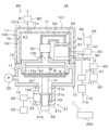
図1は、第1実施形態にかかる基板処理装置としての成膜装置の構成の概略を模式的に示す説明図であり、成膜装置の一部を断面で示している。(First embodiment)
<Film forming equipment>
FIG. 1 is an explanatory diagram schematically showing the configuration of a film forming apparatus as a substrate processing apparatus according to a first embodiment, and shows a part of the film forming apparatus in cross section.
図1の成膜装置1は、基板としてのウェハWに対し基板処理として成膜処理を行い、当該ウェハW上に例えばルテニウム(RU)膜を形成するように構成されている。
成膜装置1は、減圧可能に構成されウェハWを収容するチャンバ10を有する。The
The
チャンバ10は、例えば外形が直方体状となり且つその内部空間が円柱状になるように、形成されている。チャンバ10の材料には、熱伝導性の良い金属材料、例えばアルミニウムが用いられる。
チャンバ10の側壁11には、ウェハWの搬入出口(図示せず)が設けられており、この搬入出口には、当該搬入出口を開閉するゲートバルブ(図示せず)が設けられている。
また、チャンバ10の側壁11には、チャンバ10の外部に設けられた圧力センサ20が接続されている。圧力センサ20は、例えばキャパシタンスマノメータでありチャンバ10内の圧力を測定する。圧力センサ20での測定結果は、後述の制御部200に出力される。The
A loading/unloading port (not shown) for the wafer W is provided in the
Furthermore, a
チャンバ10の底壁12には、排気口12aが形成されている。また、底壁12には、後述のベローズ33を収容する収容部21の上部の開口21aと排気口12aとが連通するように、当該収容部21が接続されている。収容部21は、上部と側部に開口21a、21bを有し、開口21aと開口21bが互いに連通している。これら開口21a、21bを介してチャンバ10が排気されるように、収容部21の側部の開口21bには、排気管22の一端部が接続されている。排気管22の他端部は、排気装置(例えば真空ポンプ)23に接続されている。また、排気管22の排気装置23より上流側には、チャンバ10内の圧力を調整するための圧力調整弁としてのAPCバルブ24が設けられている。APCバルブ24は、自動圧力調整機能及び遮断機能を備えており、後述の制御部200からの制御信号に基づいて当該APCバルブ24の開度は制御される。APCバルブ24によって、チャンバ10内の圧力を予め設定された圧力になるよう調整したり、チャンバ10と排気装置23との接続を遮断したりすることができる。 An
チャンバ10内には、ウェハWが水平に載置される平面視円形状の載置台30が設けられている。載置台30の内部には、ウェハWを加熱するためのヒータ(図示せず)が設けられている。載置台30の下面側中央部には、チャンバ10の底壁12の排気口12aを通じて底壁12を貫通し、さらに、収容部21の底壁21cを貫通するように、上下方向に延在する支持部材31の上端部が接続されている。支持部材31の下端は、昇降機構32に接続されている。後述の制御部200に制御される昇降機構32の駆動によって、載置台30は、上方の第1の位置と下方の第2の位置との間を上下に移動することができる。 A mounting table 30 having a circular shape in plan view is provided in the
上記第1の位置は、ウェハWに処理が行われる処理位置である。処理位置に位置する載置台30と、チャンバ10の天壁13から下方に延び出しチャンバ10内の内外を仕切る隔壁13aとにより、処理空間Sが形成される。なお、処理位置に位置する載置台30の上面と隔壁13aの下面との間には隙間Kが形成されており、この隙間Kを介して処理空間S内は排気可能である。
上記第2の位置は、チャンバ10の前述の搬出入口(図示せず)からチャンバ10内に進入するウェハWの搬送機構(図示せず)と、チャンバ10内の下方に設けられた受け渡しピン(図示せず)との間で、ウェハWを受け渡している時に載置台30が待機する待機位置である。The first position is a processing position where the wafer W is processed. A processing space S is formed by the mounting table 30 located at the processing position and a
The second position is located between the transfer mechanism (not shown) for the wafer W that enters the
また、支持部材31には、フランジ31aが設けられている。そして、このフランジ31aの下面と、収容部21の底壁21cの上面との間には、支持部材31の外周を囲むように、ベローズ33が設けられている。このベローズ33が設けられているため、収容部21の底壁21cにおける支持部材31の貫通部分によってチャンバ10の気密性が失われることがない。 Further, the
また、チャンバ10内における載置台30の上方には、処理空間S内における原料ガスの流れを形成するガス流形成部材として、シャワーヘッド40が、載置台30と平行に設けられている。このシャワーヘッド40により、チャンバ10の天壁13の中央に設けられたガス供給口13bを介して供給される原料ガスが、シャワーヘッド40に設けられた複数の穴部を通過することで整流され、ウェハWに供給される。 Further, above the mounting table 30 in the
さらに、チャンバ10の天壁13には、チャンバ10に原料ガスを供給する原料ガス供給機構50が接続されている。 Furthermore, a raw material
原料ガス供給機構50は、処理ガスの供給源としての気化器51を有する。
気化器51は、処理ガスの原料を貯留し、その内部で原料が気化する。
気化器51に貯留される原料は、蒸気圧が低く、常温常圧で固体または液体の材料であり、具体的には、例えば、固体原料であるRu3(CO)12である。Ru3(CO)12は気化すなわち昇華することにより、Ru膜を形成するための原料ガスとなる。The raw material
The
The raw material stored in the
また、気化器51は、上面視でチャンバ10と重なるように配置される。具体的には、気化器51は、上面視において、その全体がチャンバ10より内側に収まり、チャンバ10より外側となる部分が存在しないように、配置される。より具体的には、気化器51は、上面視において、その全体がチャンバ10の天壁13の外周端より内側に収まり、チャンバ10の天壁13より外側となる部分が存在しないように、配置される。
気化器51は、チャンバ10の天壁13上に、直接載置されていてもよいし、支持部材を介して載置されていてもよい。Further, the
The
気化器51には、一酸化炭素(CO)ガス等のキャリアガスを供給するキャリアガス供給機構60の供給管61の一端が接続されている。供給管61の他端はキャリアガスの供給源62に接続されている。供給管61には、マスフローコントローラ等の流量調整弁(図示せず)やキャリアガスの供給を開始または停止する開閉弁を有する流量制御機構63が設けられている。また、供給管61には、キャリアガスを加熱するためのキャリアガス加熱部(図示せず)が設けられている。これら流量制御機構63やキャリアガス加熱部は後述の制御部200によって制御される。さらに、供給管61には、当該供給管61の温度制御のため、温度センサ(図示せず)が設けられている。温度センサによる測定結果は後述の制御部200に出力される。 The
キャリアガス供給機構60から気化器51に供給されたキャリアガスは、固体原料が昇華して生成された原料ガスと共に、後述の接続管52を介して、チャンバ10に供給される。 The carrier gas supplied from the carrier
また、気化器51には、その全体を覆うように、気化器加熱部(図示せず)が設けられている。気化器加熱部は、気化器51を加熱するものである。気化器加熱部による加熱によって、気化器51内の固体原料の気化すなわち昇華を促進させることができる。この気化器加熱部は、後述の制御部200によって制御される。 Further, the
さらに、気化器51には、当該気化器51内の圧力を測定する圧力センサ(図示せず)が設けられている。さらにまた、気化器51には、当該気化器51の温度の温度を測定する温度センサ(図示せず)が設けられている。これら圧力センサや温度センサでの測定結果は、後述の制御部200に出力される。 Further, the
また、原料ガス供給機構50は、気化器51からの原料ガスを供給するために、気化器51とチャンバ10とを接続する接続管52を有する。接続管52は、後述のように加熱されるため、その材料には熱伝導性の良いアルミニウムが用いられる。接続管52の一端は、気化器51に接続されており、他端は、チャンバ10の天壁13に接続されている。この接続管52を介して、気化器51内とチャンバ10内とが連通している。また、接続管52の上記一端と気化器51との接続部及び接続管52の上記他端とチャンバ10の天壁13との接続部それぞれにはメタルガスケットではなくOリングが用いられ、これら接続部分で気密性が損なわれることがないようにしている。なお、接続管52が複数の部材からなる場合は、これらの部材間の接続部分にもメタルガスケットではなくOリングが用いられる。さらに、成膜装置1では、接続管52の上記一端と気化器51との接続部、接続管52の上記他端とチャンバ10の天壁13との接続部、上記部材間の接続部には、二重Oリングは採用されていない。 Further, the raw material
接続管52には、当該接続管52内の管路を開放または閉止する開閉弁53が設けられている。この開閉弁53は後述の制御部200によって制御される。
また、接続管52における開閉弁53と気化器51との間には、気化器51内の圧力を調整するための圧力調整弁としてのAPCバルブ54が設けられている。APCバルブ54は、自動圧力調整機能及び遮断機能を備えており、後述の制御部200からの制御信号に基づいて当該APCバルブ54の開度は制御される。APCバルブ54によって、気化器51内の圧力を予め設定された圧力になるよう調整したり、接続管52内の管路を閉止したりすることができる。The connecting
Further, an
また、接続管52には、接続管加熱部(図示せず)が設けられている。接続管加熱部は、開閉弁53及びAPCバルブ54を含む接続管52全体を加熱する。これにより、原料ガスが再固化し、開閉弁53及びAPCバルブ54を含む接続管52に付着するのを防ぐことができる。 Further, the connecting
なお、原料ガスが再固化し、チャンバ10の内壁に付着することを防止するため、チャンバ10を加熱するチャンバ加熱部(図示せず)が成膜装置1には設けられている。 Note that in order to prevent the source gas from solidifying again and adhering to the inner wall of the
接続管加熱部やチャンバ加熱部は後述の制御部200によって制御される。
また、接続管加熱部による接続管52の温度制御のため、接続管52に温度センサ(図示せず)が設けられ、チャンバ加熱部によるチャンバ10の温度制御のため、チャンバ10に温度センサ(図示せず)が設けられている。これら温度センサによる測定結果は後述の制御部200に出力される。The connecting pipe heating section and the chamber heating section are controlled by a
Further, a temperature sensor (not shown) is provided on the connecting
さらに、成膜装置1は、エンクロージャ70を有する。
エンクロージャ70は、気化器51と接続管52とを囲い込むものである。具体的には、エンクロージャ70は、気化器51全体と接続管52全体とを囲い込むものであり、気化器51と接続管52との接続部分や、チャンバ10と接続管52の接続部分も囲い込む。Further, the
The
エンクロージャ70は、チャンバ10の天壁13と、カバー71と、により構成される。カバー71は、チャンバ10の天壁13との間で、気化器51及び接続管52を収容する収容空間K1を形成する。カバー71の材料には例えばアルミニウム等の金属材料が用いられる。カバー71は、例えば下部が開口した角筒状に形成され、下部の開口が平面視長方形状の天壁13に塞がれる。カバー71は、例えば天壁13に固定される。カバー71と天壁13との固定は例えばネジを用いて行われる。 The
また、カバー71は、上面視で、その全体がチャンバ10より内側に収まり、チャンバ10より外側となる部分が存在しないように、形成され配置される。具体的には、カバー71は、上面視において、その全体がチャンバ10の天壁13の外周端より内側に収まり、チャンバ10の天壁13より外側となる部分が存在しないように、形成され配置される。 Further, the
カバー71には、供給口71a及び排気口71bが形成されている。
供給口71aには、エンクロージャ70内すなわち収容空間K1内に窒素(N2)ガス等の不活性ガスを供給する不活性ガス供給機構80の供給管81の一端が接続されている。供給管81の他端は不活性ガスの供給源(図示せず)に接続されている。供給管81には、マスフローコントローラ等の流量調整弁(図示せず)や不活性ガスの供給を開始または停止する開閉弁を有する流量制御機構82が設けられている。流量制御機構82は後述の制御部200によって制御される。The
One end of a
排気口71bには、エンクロージャ70すなわち収容空間K1から排気する排気機構90の排気管91の一端が接続されている。排気管91の他端は、排気装置(例えば真空ポンプ)92に接続されている。また、排気管91には、排気量を調整する排気量調整機構93が接続されている。排気量調整機構93は、流量調整弁や、排気を開始または停止する開閉弁を有する。排気量調整機構93は後述の制御部200によって制御される。 One end of an
以上のように構成される成膜装置1には、制御部200が設けられている。制御部200は、例えばCPU等のプロセッサやメモリを備えたコンピュータにより構成され、プログラム格納部(図示せず)を有している。プログラム格納部には、成膜装置1によるウェハWの処理を実現するためのプログラムが格納されている。なお、上記プログラムは、コンピュータに読み取り可能な記憶媒体に記録されていたものであって、当該記憶媒体から制御部200にインストールされたものであってもよい。また、上記記憶媒体は、一時的なものであっても、非一時的なものであってもよい。 The
<ウェハ処理>
続いて、成膜装置1によるウェハ処理の一例について説明する。なお、このウェハ処理は、制御部200の制御により、自動的に行われる。<Wafer processing>
Next, an example of wafer processing by the
まず、開閉弁53、流量制御機構63の開閉弁及びAPCバルブ54が閉状態とされている状態において、圧力センサ20での測定結果に基づいてAPCバルブ24の開度が調整され、チャンバ10内が所定の圧力とされる。この状態で、チャンバ10のウェハWの搬出入口(図示せず)に設けられたゲートバルブ(図示せず)が開かれ、チャンバ10に隣接する真空雰囲気の搬送室(図示せず)から、上記搬出入口を介して、ウェハWを保持した搬送機構(図示せず)がチャンバ10内に挿入される。そして、ウェハWが、前述の待機位置に位置する載置台30の上方に搬送される。次いで上昇した支持ピン(図示せず)の上にウェハWが受け渡され、その後、上記搬送機構はチャンバ10から抜き出され、上記ゲートバルブが閉じられる。それと共に、上記支持ピンの下降、載置台30の上昇が行われ、載置台30上にウェハWが載置され、該載置台30が前述の処理位置へ移動され、処理空間Sが形成される。 First, in a state where the on-off
次いで、載置台30に設けられたヒータによってウェハWが所定の温度(例えば120~250℃)まで加熱される。 Next, the wafer W is heated to a predetermined temperature (for example, 120 to 250° C.) by a heater provided on the mounting table 30.
ウェハWの温度が上記所定の温度に到達すると、APCバルブ24の開度が調整され、チャンバ10内が所定の圧力(例えば5mTorr~100mTorr)へ減圧される。
チャンバ10内の減圧が完了すると、チャンバ10内の処理空間Sへの原料ガスの供給が開始されるよう、開閉弁53、流量制御機構63の開閉弁が開状態とされると共に、APCバルブ54の開度が調整される。これによって、CVD(Chemical Vapor Deposition)による、処理空間S内のウェハW上へのRu膜の形成が開始される。APCバルブ54の開度は、例えば、開閉弁53等が開状態とされてから、気化器51内の圧力が設定圧力(例えば40mTorr~150mTorr)に到達するまでの間は、段階的に大きくなるよう調整される。そして、上記設定圧力に到達すると、以後、Ru膜形成が完了するまで、APCバルブ54の開度は、気化器51内の圧力が上記設定圧力で一定になるよう調整される。When the temperature of the wafer W reaches the predetermined temperature, the opening degree of the
When the pressure reduction in the
Ru膜形成が完了すると、開閉弁53、流量制御機構63の開閉弁が閉状態にされる等して、上記と逆の手順で、ウェハWがチャンバ10から搬出される。 When the Ru film formation is completed, the on-off
なお、Ru膜の形成処理中、つまり、開閉弁53、流量制御機構63の開閉弁が開状態とされてから閉状態とされるまでの間、キャリアガス加熱部(図示せず)により所定の温度(例えば80℃)に加熱されたキャリアガスが一定流量で供給される。 Note that during the Ru film formation process, that is, from when the on-off
また、上述のウェハ処理中、気化器51、接続管52及びチャンバ10の温度は、少なくとも原料ガスが再固化しないように、対応する温度センサでの測定結果に基づいて、前述の気化器加熱部、接続管加熱部及びチャンバ加熱部によって所定の温度で一定になるように常時加熱される。例えば、接続管52及びチャンバ10は80℃で一定になるよう加熱制御され、気化器51は、接続管52やチャンバ10より若干低い温度から接続管52やチャンバ10より高い温度であって、固体原料の分解温度未満の所定の温度(例えば、上記設定圧力時の分解温度未満の70℃~100℃)で一定になるように加熱制御される。 Furthermore, during the above-mentioned wafer processing, the temperatures of the
さらに、ウェハ処理中、不活性ガス供給機構80の流量制御機構82や排気機構90の排気量調整機構93等が制御され、エンクロージャ70内すなわち収容空間K1に不活性ガスが供給される。例えば、ウェハ処理中、エンクロージャ70の外側から収容空間K1に大気が侵入しないように、当該収容空間K1はエンクロージャ70の外側の雰囲気に対して陽圧に調整される。 Furthermore, during wafer processing, the flow
<本実施形態の主な効果>
以上のように、本実施形態では、成膜装置1が、処理ガスの気化器51と接続管52とを囲い込むエンクロージャ70を有する。したがって、エンクロージャ70内すなわち収容空間K1内に不活性ガスを供給することにより、当該エンクロージャ70に囲まれている部材すなわち収容空間K1内に収容されている部材については、他の部材との接続部分から、チャンバ10に供給される処理ガスに酸素が混入するのを抑制することができる。例えば、接続管52と気化器51との接続部や接続管52とチャンバ10の天壁13との接続部等から、処理ガスに酸素が混入するのを抑制することができる。また、本実施形態では、上述のように酸素混入を抑制するために、メタルガスケットや二重Oリングを採用する必要がない。
さらに、上述のように処理ガスに酸素が混入するのを抑制することができるため、成膜装置1で形成される膜が処理ガス中の酸素の影響を受けるのを抑制することができる。<Main effects of this embodiment>
As described above, in this embodiment, the
Furthermore, since it is possible to suppress the mixing of oxygen into the processing gas as described above, it is possible to suppress the film formed by the
また、エンクロージャ70は、簡単な形状でも気化器51と接続管52とを囲い込むことができる。そのため、エンクロージャ70の開発に必要なコストは多くない。したがって、酸素混入抑制のために高コストとなるのを抑制することができる。 Moreover, the
さらにまた、本実施形態では、エンクロージャ70が、チャンバ10の天壁13と、当該天壁13との間で収容空間K1を形成するカバー71とにより構成され、当該カバー71が、上面視で、チャンバ10の内側に収まり、チャンバ10より外側となる部分が存在しない。したがって、本実施形態によれば、エンクロージャ70を設けても、成膜装置1の占有面積すなわちフットプリントが大きくなることはない。 Furthermore, in this embodiment, the
(第2実施形態)
図2は、第2実施形態にかかる基板処理装置としての成膜装置の構成の概略を模式的に示す説明図であり、成膜装置の一部を断面で示している。
図2の成膜装置1Aは、図1の成膜装置1の構成に加えて、エンクロージャ100を有する。
エンクロージャ100は、エンクロージャ70を囲い込むものである。具体的には、エンクロージャ100は、エンクロージャ70全体を囲い込むものであり、エンクロージャ70とチャンバ10の天壁13との連結部分も囲い込む。(Second embodiment)
FIG. 2 is an explanatory diagram schematically showing the configuration of a film forming apparatus as a substrate processing apparatus according to the second embodiment, and shows a part of the film forming apparatus in cross section.
The
エンクロージャ100は、チャンバ10の天壁13と、カバー101と、により構成される。カバー101は、チャンバ10の天壁13との間で、気化器51及び接続管52をエンクロージャ70のカバー71ごと収容する収容空間K2を形成する。カバー101の材料には例えばアルミニウム等の金属材料が用いられる。カバー101は、例えば下部が開口した角筒状に形成され、下部の開口が平面視長方形状の天壁13に塞がれる。カバー101は、例えば天壁13に固定される。カバー101と天壁13との固定は例えばネジを用いて行われる。 The
また、カバー101は、上面視で、その全体がチャンバ10より内側に収まり、チャンバ10より外側となる部分が存在しないように、形成され配置される。具体的には、カバー101は、上面視において、その全体がチャンバ10の天壁13の外周端より内側に収まり、チャンバ10の天壁13より外側となる部分が存在しないように、形成され配置される。 Further, the
カバー101には、排気口101a及び導入口101bが形成されている。
排気口101aには、エンクロージャ100すなわち収容空間K2から排気する排気機構110の排気管111の一端が接続されている。排気管111の他端は、排気装置(例えば真空ポンプ)112に接続されている。また、排気管111には、排気量を調整する排気量調整機構113が接続されている。排気量調整機構113は、流量調整弁や、排気を開始または停止する開閉弁を有する。排気量調整機構113は制御部200によって制御される。The
One end of an
導入口101bは、エンクロージャ100の外側に開口している。そのため、排気口101aを介してエンクロージャ100内すなわち収容空間K2を排気することにより、エンクロージャ内に不活性ガス以外のガスが導入され、具体的には大気が導入される。 The
成膜装置1Aによるウェハ処理中も、図1の成膜装置1によるウェハ処理中と同様、エンクロージャ70内すなわち収容空間K1に不活性ガスが供給されると共にエンクロージャ70内すなわち収容空間K1が排気される。 During wafer processing by the
また、成膜装置1Aによるウェハ処理中は、排気機構110の排気量調整機構113等が制御され、エンクロージャ100内すなわち収容空間K2が排気され、エンクロージャ100内すなわち収容空間K2に大気が導入される。例えば、ウェハ処理中、収容空間K2から収容空間K1に大気が侵入しないように且つ収容空間K2内の原料ガス及びキャリアガスを含み得る大気がエンクロージャ100の外側に漏れないように、収容空間K2は収容空間K1及びエンクロージャ100の外側の雰囲気に対して陰圧に調整される。 Further, during wafer processing by the
本実施形態によれば、原料ガス及びキャリアガスが万が一エンクロージャ70の外部に漏れ出しても、成膜装置1Aの外部にまで漏れ出すのを抑制することができる。 According to this embodiment, even if the raw material gas and the carrier gas should leak out of the
また、本実施形態では、エンクロージャ100が、チャンバ10の天壁13と、当該天壁13との間で収容空間K2を形成するカバー101とにより構成され、当該カバー101が、上面視で、チャンバ10の内側に収まり、チャンバ10より外側となる部分が存在しない。したがって、本実施形態によれば、エンクロージャ100を設けても、成膜装置1の占有面積すなわちフットプリントが大きくなることはない。 Further, in the present embodiment, the
(変形例)
以上では、本開示にかかる技術を、成膜装置に適用していたが、エッチング装置やクリーニング装置等の他の基板処理装置にも適用してもよい。
また、以上では、エンクロージャ70内からの排気は、排気機構90を用いて行っていた。これに代えて、不活性ガスをエンクロージャ70に供給することにより、当該エンクロージャ70内を加圧し、これによりエンクロージャ70内からの排気を行うようにしてもよい。この場合、排気機構90の排気管91以外の部材は省略してもよい。(Modified example)
In the above, the technology according to the present disclosure has been applied to a film forming apparatus, but it may also be applied to other substrate processing apparatuses such as an etching apparatus and a cleaning apparatus.
Furthermore, in the above description, the
今回開示された実施形態はすべての点で例示であって制限的なものではないと考えられるべきである。上記の実施形態は、添付の請求の範囲、後述の付記項及びその主旨を逸脱することなく、様々な形態で省略、置換、変更されてもよい。例えば、上記実施形態の構成要件は上記の効果を損なわない範囲で、任意に組み合わせることができる。また、本開示に係る技術は、上記の効果とともに、又は、上記の効果に代えて、本明細書の記載から当業者には明らかな他の効果を奏しうる。 The embodiments disclosed this time should be considered to be illustrative in all respects and not restrictive. The above-described embodiments may be omitted, replaced, or modified in various forms without departing from the scope of the appended claims, the additional notes described below, and the spirit thereof. For example, the constituent features of the embodiments described above can be combined as desired without impairing the effects described above. Further, the technology according to the present disclosure may have other effects that are obvious to those skilled in the art from the description of this specification, in addition to or in place of the above effects.
なお、以下のような構成も本開示の技術的範囲に属する。
[付記項1]
減圧可能に構成され、基板が収容されるチャンバと、
前記チャンバに供給される処理ガスの供給源と、当該供給源と前記チャンバとを接続する接続管とを囲い込むエンクロージャと、を有する、基板処理装置。
[付記項2]
前記エンクロージャは、
当該エンクロージャ内に不活性ガスを供給する供給管と、
当該エンクロージャから排気する排気管と、が接続されている、付記項1に記載の基板処理装置。
[付記項3]
前記供給源は、処理ガスの原料を貯留し、内部で原料が気化する気化器である、付記項1または2に記載の基板処理装置。
[付記項4]
前記原料は、常温常圧で固体または液体である、付記項3に記載の基板処理装置。
[付記項5]
前記原料は、気化することにより、ルテニウム膜を形成するための原料ガスとなる、付記項4に記載の基板処理装置。
[付記項6]
前記供給源は、上面視で前記チャンバと重なるように配置される、付記項1~5のいずれか1項に記載の基板処理装置。
[付記項7]
前記エンクロージャは、
前記チャンバの天壁と、
前記供給源及び接続管を収容する収容空間を前記天壁との間で形成するカバーとにより構成され、
前記カバーは、上面視で、前記チャンバの内側に収まるように形成されている、付記項6に記載の基板処理装置。
[付記項8]
前記エンクロージャを囲い込む他のエンクロージャをさらに有する、付記項1~5のいずれか1項に記載の基板処理装置。
[付記項9]
前記エンクロージャを囲い込む他のエンクロージャをさらに有する、付記項6に記載の基板処理装置。
[付記項10]
前記エンクロージャを囲い込む他のエンクロージャをさらに有する、付記項7に記載の基板処理装置。
[付記項11]
前記他のエンクロージャは、
前記チャンバの天壁と、
前記供給源及び接続管を前記カバーごと収容する他の収容空間を前記天壁との間で形成する他のカバーとにより構成され、
前記他のカバーは、上面視で、前記チャンバの内側に収まるように形成されている、付記項10に記載の基板処理装置。
[付記項12]
前記他のエンクロージャは、当該他のエンクロージャから排気する排気管が接続されている、付記項8~11のいずれか1項に記載の基板処理装置。
[付記項13]
減圧可能に構成され基板が収容される基板処理装置のチャンバに対する処理ガスの供給源と、当該供給源と前記チャンバとを接続する接続管と、を、エンクロージャで囲い込むことにより、前記チャンバに供給される前記処理ガスへの酸素混入を抑制する方法。Note that the following configurations also belong to the technical scope of the present disclosure.
[Additional note 1]
a chamber configured to be capable of reducing pressure and containing a substrate;
A substrate processing apparatus, comprising: an enclosure that encloses a supply source of processing gas supplied to the chamber and a connecting pipe connecting the supply source and the chamber.
[Additional note 2]
The enclosure is
a supply pipe for supplying inert gas into the enclosure;
[Additional note 3]
The substrate processing apparatus according to
[Additional note 4]
Supplementary Note 3. The substrate processing apparatus according to Supplementary Note 3, wherein the raw material is solid or liquid at room temperature and pressure.
[Additional note 5]
The substrate processing apparatus according to
[Additional note 6]
6. The substrate processing apparatus according to any one of
[Additional note 7]
The enclosure is
a ceiling wall of the chamber;
a cover that forms an accommodation space for accommodating the supply source and the connecting pipe with the ceiling wall;
The substrate processing apparatus according to appendix 6, wherein the cover is formed to fit inside the chamber when viewed from above.
[Additional Note 8]
The substrate processing apparatus according to any one of
[Additional Note 9]
6. The substrate processing apparatus according to claim 6, further comprising another enclosure surrounding the enclosure.
[Additional Note 10]
The substrate processing apparatus according to supplementary note 7, further comprising another enclosure surrounding the enclosure.
[Additional Note 11]
The other enclosure is
a ceiling wall of the chamber;
and another cover that forms another housing space between the ceiling wall and the housing space that accommodates the supply source and the connecting pipe together with the cover,
The substrate processing apparatus according to
[Additional Note 12]
The substrate processing apparatus according to any one of Supplementary Notes 8 to 11, wherein the other enclosure is connected to an exhaust pipe that exhausts air from the other enclosure.
[Additional Note 13]
A processing gas supply source for a chamber of a substrate processing apparatus that is configured to be able to reduce pressure and accommodates a substrate, and a connecting pipe that connects the supply source and the chamber are enclosed in an enclosure to supply the processing gas to the chamber. A method of suppressing oxygen contamination into the processing gas.
1、1A…成膜装置
10…チャンバ
51…気化器
70…エンクロージャ1, 1A...
Claims (13)
Translated fromJapanese前記チャンバに供給される処理ガスの供給源と、当該供給源と前記チャンバとを接続する接続管とを囲い込むエンクロージャと、を有する、基板処理装置。a chamber configured to be capable of reducing pressure and containing a substrate;
A substrate processing apparatus, comprising: an enclosure that encloses a supply source of processing gas supplied to the chamber and a connecting pipe connecting the supply source and the chamber.
当該エンクロージャ内に不活性ガスを供給する供給管と、
当該エンクロージャから排気する排気管と、が接続されている、請求項1に記載の基板処理装置。The enclosure is
a supply pipe for supplying inert gas into the enclosure;
The substrate processing apparatus according to claim 1, further connected to an exhaust pipe that exhausts air from the enclosure.
前記チャンバの天壁と、
前記供給源及び接続管を収容する収容空間を前記天壁との間で形成するカバーとにより構成され、
前記カバーは、上面視で、前記チャンバの内側に収まるように形成されている、請求項6に記載の基板処理装置。The enclosure is
a ceiling wall of the chamber;
a cover that forms an accommodation space for accommodating the supply source and the connecting pipe with the ceiling wall;
The substrate processing apparatus according to claim 6, wherein the cover is formed to fit inside the chamber when viewed from above.
前記チャンバの天壁と、
前記供給源及び接続管を前記カバーごと収容する他の収容空間を前記天壁との間で形成する他のカバーとにより構成され、
前記他のカバーは、上面視で、前記チャンバの内側に収まるように形成されている、請求項10に記載の基板処理装置。The other enclosure is
a ceiling wall of the chamber;
and another cover that forms another housing space between the ceiling wall and the housing space that accommodates the supply source and the connecting pipe together with the cover,
The substrate processing apparatus according to claim 10, wherein the other cover is formed to fit inside the chamber when viewed from above.
A processing gas supply source for a chamber of a substrate processing apparatus that is configured to be able to reduce pressure and accommodates a substrate, and a connection pipe that connects the supply source and the chamber are enclosed in an enclosure to supply the processing gas to the chamber. A method of suppressing oxygen contamination into the processing gas.
Priority Applications (5)
| Application Number | Priority Date | Filing Date | Title |
|---|---|---|---|
| JP2022085097AJP2023173097A (en) | 2022-05-25 | 2022-05-25 | Substrate treatment apparatus and method for suppressing oxygen contamination |
| PCT/JP2023/017728WO2023228763A1 (en) | 2022-05-25 | 2023-05-11 | Substrate treatment device and method for suppressing oxygen entry |
| KR1020247041229AKR20250011151A (en) | 2022-05-25 | 2023-05-11 | Substrate processing device and oxygen mixing suppression method |
| CN202380039537.6ACN119173650A (en) | 2022-05-25 | 2023-05-11 | Substrate processing apparatus and oxygen mixing suppression method |
| US18/951,419US20250075319A1 (en) | 2022-05-25 | 2024-11-18 | Substrate processing apparatus and method of suppressing oxygen incorporation |
Applications Claiming Priority (1)
| Application Number | Priority Date | Filing Date | Title |
|---|---|---|---|
| JP2022085097AJP2023173097A (en) | 2022-05-25 | 2022-05-25 | Substrate treatment apparatus and method for suppressing oxygen contamination |
Publications (1)
| Publication Number | Publication Date |
|---|---|
| JP2023173097Atrue JP2023173097A (en) | 2023-12-07 |
Family
ID=88919128
Family Applications (1)
| Application Number | Title | Priority Date | Filing Date |
|---|---|---|---|
| JP2022085097APendingJP2023173097A (en) | 2022-05-25 | 2022-05-25 | Substrate treatment apparatus and method for suppressing oxygen contamination |
Country Status (5)
| Country | Link |
|---|---|
| US (1) | US20250075319A1 (en) |
| JP (1) | JP2023173097A (en) |
| KR (1) | KR20250011151A (en) |
| CN (1) | CN119173650A (en) |
| WO (1) | WO2023228763A1 (en) |
Family Cites Families (7)
| Publication number | Priority date | Publication date | Assignee | Title |
|---|---|---|---|---|
| US5451258A (en)* | 1994-05-11 | 1995-09-19 | Materials Research Corporation | Apparatus and method for improved delivery of vaporized reactant gases to a reaction chamber |
| JP2000150387A (en)* | 1998-11-18 | 2000-05-30 | Applied Materials Inc | Piping system structure and piping unit |
| JP5152105B2 (en) | 2002-08-23 | 2013-02-27 | 東京エレクトロン株式会社 | Processing system |
| JP5528374B2 (en)* | 2011-03-03 | 2014-06-25 | 東京エレクトロン株式会社 | Gas decompression supply device, cylinder cabinet including the same, valve box, and substrate processing apparatus |
| CN117936420A (en)* | 2017-11-11 | 2024-04-26 | 微材料有限责任公司 | Gas delivery system for high pressure processing chamber |
| JP7094172B2 (en)* | 2018-07-20 | 2022-07-01 | 東京エレクトロン株式会社 | Film forming equipment, raw material supply equipment and film forming method |
| JP7134863B2 (en)* | 2018-12-27 | 2022-09-12 | 東京エレクトロン株式会社 | Plasma processing apparatus and plasma processing method |
- 2022
- 2022-05-25JPJP2022085097Apatent/JP2023173097A/enactivePending
- 2023
- 2023-05-11WOPCT/JP2023/017728patent/WO2023228763A1/ennot_activeCeased
- 2023-05-11CNCN202380039537.6Apatent/CN119173650A/enactivePending
- 2023-05-11KRKR1020247041229Apatent/KR20250011151A/enactivePending
- 2024
- 2024-11-18USUS18/951,419patent/US20250075319A1/enactivePending
Also Published As
| Publication number | Publication date |
|---|---|
| US20250075319A1 (en) | 2025-03-06 |
| KR20250011151A (en) | 2025-01-21 |
| WO2023228763A1 (en) | 2023-11-30 |
| CN119173650A (en) | 2024-12-20 |
Similar Documents
| Publication | Publication Date | Title |
|---|---|---|
| US5484484A (en) | Thermal processing method and apparatus therefor | |
| US20150221529A1 (en) | Gas supply method and thermal treatment method | |
| US12281389B2 (en) | Substrate processing method and substrate processing apparatus | |
| KR101210456B1 (en) | Method of manufacturing semiconductor device, method of processing substrate and substrate processing apparatus | |
| JP2012212854A (en) | Substrate processing device and solid raw material replenishing method | |
| US11124872B2 (en) | Substrate processing apparatus | |
| US8586140B2 (en) | Film formation method for forming hafnium oxide film | |
| KR102699806B1 (en) | Deposition apparatus and deposition method | |
| KR102358308B1 (en) | Substrate processing apparatus, method of removing particles in injector, and substrate processing method | |
| KR101156305B1 (en) | METHOD FOR FORMING SrTiO3 FILM AND STORAGE MEDIUM | |
| US11981992B2 (en) | Method for forming RuSi film and substrate processing system | |
| WO2020179575A1 (en) | Film-forming apparatus and material gas feeding method | |
| JP2023173097A (en) | Substrate treatment apparatus and method for suppressing oxygen contamination | |
| KR102518959B1 (en) | Substrate processing apparatus, substrate loading method, and substrate processing method | |
| CN113056962A (en) | Gas supply device and gas supply method | |
| JP7529764B2 (en) | Substrate processing apparatus, semiconductor device manufacturing method and program | |
| KR20230028471A (en) | Film formation method and film formation apparatus | |
| US20240183030A1 (en) | Substrate treatment apparatus using supercritical fluid | |
| JP2011114002A (en) | Substrate treating device | |
| JP7281519B2 (en) | SUBSTRATE PROCESSING APPARATUS, SEMICONDUCTOR DEVICE MANUFACTURING METHOD, AND PROCESSING CONTAINER | |
| JP4652785B2 (en) | Substrate processing equipment | |
| JP2023046423A (en) | Deposition method and deposition device | |
| JP2018145460A (en) | Gas introduction mechanism and heat treatment apparatus | |
| JP2011060812A (en) | Substrate processing device | |
| JP2007258221A (en) | Substrate processing equipment |
Legal Events
| Date | Code | Title | Description |
|---|---|---|---|
| A621 | Written request for application examination | Free format text:JAPANESE INTERMEDIATE CODE: A621 Effective date:20250226 |