JP2023166889A - Cooling device - Google Patents
Cooling deviceDownload PDFInfo
- Publication number
- JP2023166889A JP2023166889AJP2022077742AJP2022077742AJP2023166889AJP 2023166889 AJP2023166889 AJP 2023166889AJP 2022077742 AJP2022077742 AJP 2022077742AJP 2022077742 AJP2022077742 AJP 2022077742AJP 2023166889 AJP2023166889 AJP 2023166889A
- Authority
- JP
- Japan
- Prior art keywords
- refrigerant
- cooling device
- base material
- case material
- case
- Prior art date
- Legal status (The legal status is an assumption and is not a legal conclusion. Google has not performed a legal analysis and makes no representation as to the accuracy of the status listed.)
- Pending
Links
Images


Classifications
- H—ELECTRICITY
- H04—ELECTRIC COMMUNICATION TECHNIQUE
- H04N—PICTORIAL COMMUNICATION, e.g. TELEVISION
- H04N9/00—Details of colour television systems
- H04N9/12—Picture reproducers
- H04N9/31—Projection devices for colour picture display, e.g. using electronic spatial light modulators [ESLM]
- H04N9/3141—Constructional details thereof
- H04N9/3144—Cooling systems
- H—ELECTRICITY
- H05—ELECTRIC TECHNIQUES NOT OTHERWISE PROVIDED FOR
- H05K—PRINTED CIRCUITS; CASINGS OR CONSTRUCTIONAL DETAILS OF ELECTRIC APPARATUS; MANUFACTURE OF ASSEMBLAGES OF ELECTRICAL COMPONENTS
- H05K7/00—Constructional details common to different types of electric apparatus
- H05K7/20—Modifications to facilitate cooling, ventilating, or heating
- H05K7/20218—Modifications to facilitate cooling, ventilating, or heating using a liquid coolant without phase change in electronic enclosures
- H05K7/20254—Cold plates transferring heat from heat source to coolant
- H—ELECTRICITY
- H01—ELECTRIC ELEMENTS
- H01L—SEMICONDUCTOR DEVICES NOT COVERED BY CLASS H10
- H01L23/00—Details of semiconductor or other solid state devices
- H01L23/34—Arrangements for cooling, heating, ventilating or temperature compensation ; Temperature sensing arrangements
- H01L23/40—Mountings or securing means for detachable cooling or heating arrangements ; fixed by friction, plugs or springs
- H01L23/4006—Mountings or securing means for detachable cooling or heating arrangements ; fixed by friction, plugs or springs with bolts or screws
- H—ELECTRICITY
- H01—ELECTRIC ELEMENTS
- H01L—SEMICONDUCTOR DEVICES NOT COVERED BY CLASS H10
- H01L23/00—Details of semiconductor or other solid state devices
- H01L23/34—Arrangements for cooling, heating, ventilating or temperature compensation ; Temperature sensing arrangements
- H01L23/46—Arrangements for cooling, heating, ventilating or temperature compensation ; Temperature sensing arrangements involving the transfer of heat by flowing fluids
- H01L23/473—Arrangements for cooling, heating, ventilating or temperature compensation ; Temperature sensing arrangements involving the transfer of heat by flowing fluids by flowing liquids
- H—ELECTRICITY
- H05—ELECTRIC TECHNIQUES NOT OTHERWISE PROVIDED FOR
- H05K—PRINTED CIRCUITS; CASINGS OR CONSTRUCTIONAL DETAILS OF ELECTRIC APPARATUS; MANUFACTURE OF ASSEMBLAGES OF ELECTRICAL COMPONENTS
- H05K7/00—Constructional details common to different types of electric apparatus
- H05K7/20—Modifications to facilitate cooling, ventilating, or heating
- H05K7/20218—Modifications to facilitate cooling, ventilating, or heating using a liquid coolant without phase change in electronic enclosures
- H05K7/20263—Heat dissipaters releasing heat from coolant
Landscapes
- Engineering & Computer Science (AREA)
- Microelectronics & Electronic Packaging (AREA)
- Physics & Mathematics (AREA)
- Thermal Sciences (AREA)
- Condensed Matter Physics & Semiconductors (AREA)
- General Physics & Mathematics (AREA)
- Computer Hardware Design (AREA)
- Power Engineering (AREA)
- Multimedia (AREA)
- Signal Processing (AREA)
- Cooling Or The Like Of Semiconductors Or Solid State Devices (AREA)
- Cooling Or The Like Of Electrical Apparatus (AREA)
Abstract
Description
Translated fromJapanese本発明は、発熱体を冷却するための冷却システムに用いるための冷却装置に関する。 The present invention relates to a cooling device for use in a cooling system for cooling a heating element.
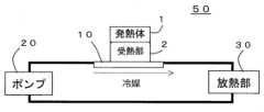
図1は、発熱体1を冷却する冷媒を用いた冷却装置10を含む液冷型の冷却システム50の構成を示す概略図である。発熱体1を冷却するための冷却システムでは、例えば、ポンプ20と放熱部30との間に発熱体1からの熱を冷媒と熱交換するための熱交換部を有する冷却装置を配置して、冷媒を冷却装置に供給して、その熱を冷媒で受け、放熱部30で放熱させて冷媒を冷却し、ポンプ20を介して冷媒を循環させている。 FIG. 1 is a schematic diagram showing the configuration of a liquid cooling
発熱体が、例えば、プロジェクタで用いられる表示装置におけるデジタルマイクロミラー(DMD)などの部材の場合には、DMDが配置されている基板等の電気接点との物理的干渉を回避する必要がある。このため、発熱体と接触する冷却装置の受熱部を一部分に限定的にする必要がある。 When the heating element is, for example, a member such as a digital micromirror (DMD) in a display device used in a projector, it is necessary to avoid physical interference with electrical contacts such as a substrate on which the DMD is arranged. For this reason, it is necessary to limit the heat receiving portion of the cooling device that comes into contact with the heating element to a limited portion.
例えば、下部に発熱体を配置し、上部から冷媒を供給して冷却する電子機器用の冷却装置及び受熱部材が開示されている(例えば、特許文献1参照。)。 For example, a cooling device and a heat receiving member for electronic equipment have been disclosed in which a heating element is disposed in the lower part and a refrigerant is supplied from the upper part to cool the electronic equipment (see, for example, Patent Document 1).
受熱部から熱伝導させるためのフィン等の熱交換部は一定の配置とすることが望ましい。これに対して、冷却システムにおいて、冷却装置と接続する配管は、図12(a)に示されるように冷媒の配管の配置が限定される場合がある。そのため、冷却システムの配置と、受熱部と冷媒の配管の向きとの関係が適切でない場合には、冷媒の配管が冗長になったり、配置すべき箇所と干渉して使用できない場合が生じるという課題があった。 It is desirable that heat exchange parts such as fins for conducting heat from the heat receiving part be arranged in a fixed manner. On the other hand, in a cooling system, the arrangement of refrigerant piping may be limited as shown in FIG. 12(a) for piping connected to a cooling device. Therefore, if the relationship between the placement of the cooling system and the orientation of the heat receiving part and the refrigerant piping is not appropriate, the refrigerant piping may become redundant or may interfere with the location where it should be placed, making it unusable. was there.
そこで、本開示は、冷媒の配管の向きを適宜変更できる冷却装置を提供することを目的とする。 Therefore, an object of the present disclosure is to provide a cooling device that can appropriately change the direction of refrigerant piping.
本開示に係る冷却装置は、第1の面に発熱体が配置され、前記第1の面とは反対側の第2の面に前記発熱体からの熱を受熱し、冷媒との熱交換を行う熱交換部が設けられているベース材と、ベース材の熱交換部に冷媒を供給する冷媒流入口及び冷媒流出口を備えたケース材と、を備え、ケース材は、ベース材に対して、冷媒流入口及び冷媒流出口が第1の方向に取り付けられた第1の形態と、冷媒流入口及び冷媒流出口が第1の方向と異なる第2の方向に取り付けられた第2の形態との2つの形態で取付け可能である。 The cooling device according to the present disclosure includes a heating element disposed on a first surface, receiving heat from the heating element on a second surface opposite to the first surface, and exchanging heat with a refrigerant. A base material is provided with a heat exchange section that performs heat exchange, and a case material is provided with a refrigerant inlet and a refrigerant outlet that supply refrigerant to the heat exchange section of the base material. , a first form in which the refrigerant inlet and the refrigerant outlet are installed in a first direction, and a second form in which the refrigerant inlet and the refrigerant outlet are installed in a second direction different from the first direction. It can be installed in two ways.
本開示に係る冷却装置によれば、冷媒の配管の向きを適宜変更することができる。これによって、様々な冷却システムの配置に対応させることができる。 According to the cooling device according to the present disclosure, the direction of the refrigerant piping can be changed as appropriate. This makes it possible to accommodate various cooling system arrangements.
第1の態様に係る冷却装置は、第1の面に発熱体が配置され、第1の面とは反対側の第2の面に発熱体からの熱を受熱し、冷媒との熱交換を行う熱交換部が設けられているベース材と、ベース材の熱交換部に冷媒を供給する冷媒流入口及び冷媒流出口を備えたケース材と、を備え、ケース材は、ベース材に対して、冷媒流入口及び冷媒流出口が第1の方向に取り付けられた第1の形態と、冷媒流入口及び冷媒流出口が第1の方向と異なる第2の方向に取り付けられた第2の形態との2つの形態で取付け可能である。 In the cooling device according to the first aspect, the heating element is disposed on the first surface, the second surface opposite to the first surface receives heat from the heating element, and exchanges heat with the refrigerant. A base material is provided with a heat exchange section that performs heat exchange, and a case material is provided with a refrigerant inlet and a refrigerant outlet that supply refrigerant to the heat exchange section of the base material. , a first form in which the refrigerant inlet and the refrigerant outlet are installed in a first direction, and a second form in which the refrigerant inlet and the refrigerant outlet are installed in a second direction different from the first direction. It can be installed in two ways.
第2の態様に係る冷却装置は、上記第1の態様において、熱交換部は、フィンが平行に複数並べられた形状を有してもよい。 In the cooling device according to the second aspect, in the first aspect, the heat exchange section may have a shape in which a plurality of fins are arranged in parallel.
第3の態様に係る冷却装置は、上記第1又は第2の態様において、ケース材は、第1のケース材と第2のケース材とを含み、第1のケース材は、熱交換部に冷媒を流すように構成され、第2のケース材は、冷媒流入口と冷媒流出口とを備え、第1のケース材を保持しながら、ベース材に取付け可能であってもよい。 In the cooling device according to a third aspect, in the first or second aspect, the case material includes a first case material and a second case material, and the first case material is arranged in the heat exchange section. The second case material may be configured to allow a refrigerant to flow therethrough, include a refrigerant inlet and a refrigerant outlet, and may be attachable to the base material while holding the first case material.
第4の態様に係る冷却装置は、上記第3の態様において、ベース材は、ケース材に対して、円周に沿って配置された複数のネジ孔についてネジ止めされており、第1の形態に対応する複数のネジ孔でネジ止めしてベース材とケース材とを第1の形態で取付け可能であり、第2の形態に対応する複数のネジ孔でネジ止めしてベース材とケース材とを前記第2の形態で取付け可能であってもよい。 In the cooling device according to the fourth aspect, in the third aspect, the base material is screwed to the case material through a plurality of screw holes arranged along the circumference, and It is possible to attach the base material and the case material in the first form by screwing them together using a plurality of screw holes corresponding to the above, and to attach the base material and the case material together using a plurality of screw holes corresponding to the second form. and may be attachable in the second form.
第5の態様に係る冷却装置は、上記第4の態様において、複数のネジ孔は、円周に沿って等間隔に配置されていてもよい。 In the cooling device according to the fifth aspect, in the fourth aspect, the plurality of screw holes may be arranged at equal intervals along the circumference.
第6の態様に係る冷却装置は、上記第4の態様において、第2のケース材は、中心に冷媒を流通させる筒状溝と、筒状溝と同心円状に外周方向に冷媒を流通させる環状溝と、を有し、筒状溝が冷媒流入口と接続され、環状溝が冷媒流出口と接続されていてもよい。 In the cooling device according to a sixth aspect, in the fourth aspect, the second case material has a cylindrical groove through which the refrigerant flows through the center, and an annular groove through which the refrigerant flows in the outer circumferential direction concentrically with the cylindrical groove. The cylindrical groove may be connected to the refrigerant inlet, and the annular groove may be connected to the refrigerant outlet.
第7の態様に係る冷却装置は、上記第6の態様において、第1のケース材は、第2のケース材の筒状溝から熱交換部に向かう冷媒の流路を画成すると共に、熱交換部から前記環状溝への冷媒の流路を画成してもよい。 In the cooling device according to a seventh aspect, in the sixth aspect, the first case material defines a flow path for the refrigerant from the cylindrical groove of the second case material toward the heat exchange section, and A refrigerant flow path may be defined from the exchange portion to the annular groove.
第8の態様に係る冷却装置は、上記第3の態様において、ベース材は、ケース材に対して、把持部材によってベース材とケース材とを把持していてもよい。 In the cooling device according to the eighth aspect, in the third aspect, the base material may hold the base material and the case material with respect to the case material using a gripping member.
以下、実施の形態に係る冷却装置について、添付図面を参照しながら説明する。なお、図面において実質的に同一の部材については同一の符号を付している。 Hereinafter, a cooling device according to an embodiment will be described with reference to the accompanying drawings. In the drawings, substantially the same members are designated by the same reference numerals.
(実施の形態1)
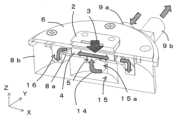
図2は、実施の形態1に係る冷却装置10の外観を示す概略斜視図である。図3は、図2の冷却装置10の主要な構成部材の概要を示す分解斜視図である。なお、図面において、便宜上、ベース材6の発熱体1が配置されている面がXY面であり、このXY面に垂直な方向がZ方向であり、図2で冷媒流出入口9a、9bが設けられている方向をY方向として示している。また、XY面でY方向と垂直な方向をX方向としている。
実施の形態1に係る冷却装置10は、第1の面に発熱体1が配置され、第2の面に冷媒との熱交換を行う熱交換部4が設けられているベース材6と、ベース材6の熱交換部4に冷媒を供給する冷媒流入口9a及び冷媒流出口9bを備えたケース材8(8a、8b)と、を備える。第2の面は、第1の面とは反対側の面である。また、熱交換部4では、発熱体1からの熱を受熱し、冷媒と熱交換する。ケース材8は、ベース材6に対して、冷媒流入口9a及び冷媒流出口9bが第1の方向に取り付けられた第1の形態と、冷媒流入口9a及び冷媒流出口9bが第1の方向と異なる第2の方向に取り付けられた第2の形態との2つの形態で取付け可能である。
上記構成によって、冷媒の配管の向きを適宜変更することができる。これによって、表示装置、電子部品等の発熱体についての様々な冷却システムの配置に対応させることができる。(Embodiment 1)
FIG. 2 is a schematic perspective view showing the appearance of the
A cooling
With the above configuration, the direction of the refrigerant piping can be changed as appropriate. This makes it possible to accommodate various arrangements of cooling systems for heat generating elements such as display devices and electronic components.
以下に、この冷却装置10を構成する各部材について説明する。 Each member constituting this
<発熱体>
発熱体1は、例えば、表示装置におけるデジタルマイクロミラー(DMD)である。また、電子部品であってもよい。なお、発熱体1は、上記のものに限定されない。<Heating element>
The
<受熱部>
受熱部2は、発熱体1と接触して受熱する。また、受熱部2は、ベース材6の表面(第1の面)に設けられており、裏面(第2の面)に設けられた熱交換部4と熱伝導で熱を伝える。受熱部2の形状は、図2及び図3等では長方形であるが、これに限定されず、発熱体1と接触できる形状であればよい。例えば、多角形、円形、楕円形等であってもよい。<Heat receiving part>
The
<冷媒>
冷媒14は、例えば、不凍液である。また、エチレングリコール、プロピレングリコール等を用いることができる。なお、上記の例に限られない。<Refrigerant>
The refrigerant 14 is, for example, antifreeze. Furthermore, ethylene glycol, propylene glycol, etc. can be used. Note that the example is not limited to the above example.
<ベース材>
図4は、実施の形態1に係る冷却装置10を構成するベース材6の裏面(第2の面)の構成を示す概略斜視図である。ベース材6は、図3に示すように、第1の面(表面)に発熱体1が配置され、図4に示すように、第1の面とは反対側の第2の面(裏面)に発熱体1からの熱を冷媒に移動させる熱交換部4が設けられている。<Base material>
FIG. 4 is a schematic perspective view showing the configuration of the back surface (second surface) of the
また、ベース材6は、ケース材8(8b)に対して、円周に沿って配置された複数のネジ孔12についてネジ11によってネジ止めされている。複数のネジ孔12は、例えば、円周に沿って等間隔に設けられている。なお、ベース材6とケース材8との取付けは、上記ネジによる場合に限られない。例えば、板バネ等の把持部材によって、ベース材6とケース材8とを取付けてもよい。 Further, the
<熱交換部>
熱交換部4は、例えば、板状のフィン4aが平行に複数並べられた形状である。複数のフィン4aの間を冷媒が流れる。熱交換部4は、ベース材6の裏面(第2の面)に設けられ、表面(第1の面)に配置された発熱体1及び受熱部2からの熱を受熱する。複数のフィン4aは、実質的に同一の形状を有し、平行に配置されている。例えば、0.2mm~0.3mmのピッチのマイクロフィンであってもよい。
なお、熱交換部4は、上記の場合に限られない。例えば、フィンが板状フィンではなく、丸形の柱状フィンであってもよい。この場合には、例えば、柱状フィンを正方格子状、三角格子状等に配置してもよい。あるいはランダムに配置してもよい。<Heat exchange section>
The
Note that the
また、熱交換部4のフィン4aは、発熱体1及び受熱部2の構成及び形状に応じて適切な構成及び配置とすることができる。この場合、発熱体1と熱交換部4のフィン4aとの配置が特定の配置となる。このため、熱交換部4を有するベース材6の方向が発熱体1に対して一定の方向に設定される場合がある。 Further, the fins 4a of the
<ケース材>
図3に示すように、ケース材8は、ベース材6の熱交換部4に冷媒を供給する冷媒流入口9a及び冷媒流出口9bを備える。ケース材8は、ベース材に対して、冷媒流入口9a及び冷媒流出口9bが複数の方向に取付け可能になっている。具体的には、ケース材8は、ベース材6に対して、冷媒流入口9a及び冷媒流出口9bが第1の方向に取り付けられた第1の形態と、冷媒流入口9a及び冷媒流出口9bが第1の方向と異なる第2の方向に取り付けられた第2の形態との2つの形態で取付け可能である。ケース材8は、第1のケース材8aと第2のケース材8bとを含む。<Case material>
As shown in FIG. 3, the
<第1のケース材>
図5は、実施の形態1に係る冷却装置10を構成する第1のケース材8aの概要を示す概略斜視図である。第1のケース材8aは、ベース材6の熱交換部4と第2のケース材8bとの間に配置され、開口部5を介して熱交換部4に沿って冷媒を流すように構成されている。第1のケース材8aは、例えば、ゴム製のゴムシートである。この第1のケース材8aは、複数のフィン4aの上面と密着して、開口部5から冷媒をフィン4aの間の流路に冷媒を導く役割を有する(図7~9にて後述する。)。これによって、冷媒流入口9aから流入する冷媒が熱交換部4のフィン4aの間の溝を通らずに、熱交換せずに流出していくことを抑制できる。<First case material>
FIG. 5 is a schematic perspective view showing an outline of the first case member 8a that constitutes the
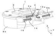
<第2のケース材>
図6は、実施の形態1に係る冷却装置10を構成する第2のケース材8bの概要を示す概略斜視図である。第2のケース材8bは、冷媒流入口9aと冷媒流出口9bとを備え、第1のケース材8aを保持しながら、ベース材6について、複数の方向に取付可能である。第2のケース材8bは、中心に冷媒を流通させる筒状溝15と、筒状溝15と同心円状に外周方向に冷媒を流通させる環状溝16と、を有する。筒状溝15が冷媒流入口9aと接続され、環状溝16が冷媒流出口9bと接続されている。第2のケース材には、例えば、第1のケース材8aを嵌め込む「だぐり」を設けてもよい。上記第1のケース材8a及び第2のケース材8bによって、熱交換部4から第2のケース材8bの環状溝16への冷媒の流路を画成できる。
また、第2のケース材8bも円周に沿って配置された複数のネジ孔13を有する。ベース材6のネジ孔12と第2のケース材8bのネジ孔13とをそれぞれ対応させてネジ11によってネジ止めすることで、ベース材6とケース材8とを取り付けることができる。なお、ベース材6とケース材8とのそれぞれの対向面には、例えば、水漏れを防止するためのOリングゴム挿入用溝を設けている。<Second case material>
FIG. 6 is a schematic perspective view showing an outline of the second case member 8b that constitutes the
Further, the second case member 8b also has a plurality of screw holes 13 arranged along the circumference. The
<冷媒流出入口>
冷媒流入口9aと冷媒流出口9bとは、図2及び図3に示すように、いずれも同じY方向に配置してもよい。あるいは、冷媒流入口9aと冷媒流出口9bとをそれぞれ別々の方向に配置してもよい。例えば、第2のケース材8bを挟んで、冷媒流入口9aと冷媒流出口9bとを+Y方向と-Y方向とにそれぞれ配置してもよい。<Refrigerant inlet>
The refrigerant inlet 9a and the refrigerant outlet 9b may be arranged in the same Y direction, as shown in FIGS. 2 and 3. Alternatively, the refrigerant inlet 9a and the refrigerant outlet 9b may be arranged in different directions. For example, the refrigerant inlet 9a and the refrigerant outlet 9b may be arranged in the +Y direction and the -Y direction, respectively, with the second case member 8b in between.
<冷媒の流れについて>
図7は、図2の冷却装置10について、冷媒流入口9aからの冷媒14の流入方向に垂直な断面における冷媒14の流れを示す概略断面図である。図8は、図2の冷却装置10について、冷媒流入口9aから冷媒14の流入方向に平行な断面における冷媒14の流れを示す概略断面図である。図9は、図2の冷却装置10について、冷媒流出口9bへの冷媒14の流出方向に平行な断面における冷媒14の流れを示す概略断面図である。
冷媒流入口9aから流入した冷媒14は、入口15aを介して第2のケース材8bの中央の筒状溝15に導かれる。筒状溝15に導かれた冷媒14は、Z方向上方に配置された第1のケース材8aの開口部5を介して熱交換部4の平行に配置されたフィン4aの間に導かれる。フィン4aの間に導かれた冷媒14は、フィン4aの延在方向に沿って+X方向及び-X方向の両方向に流れる。このとき、発熱体1から受熱部2へ、そして、受熱部2からフィン4aに流れてきた熱3は、フィン4aから冷媒14に移行する。その後、冷媒14は、フィン4aの両端から筒状溝15と同心円状に外周に設けられた環状溝16に入り、環状溝16に沿って外周を巡って、出口16aを介して冷媒流出口9bから流出する。冷媒14は、例えば、図1に示すように、配管を介して放熱部30で熱を放熱して、ポンプ20を介して冷却装置10へと循環する。
なお、冷媒流入口9aのZ方向における高さと冷媒流出口9bのZ方向における高さとは、図8及び図9に示すように、冷媒流入口9aより冷媒流出口9bのほうが高くなっているが、これに限られない。両者が同じ高さであってもよい。あるいは逆であってもよい。
また、冷媒14が流れる方向は、上記方向に限られない。冷媒14は、例えば、逆方向に流れてもよい。この場合、冷媒流入口と冷媒流出口との符号が入れ替わる構成であってもよい。<About the flow of refrigerant>
FIG. 7 is a schematic sectional view showing the flow of the refrigerant 14 in the
The refrigerant 14 that has flowed in from the refrigerant inlet 9a is guided to the central
Note that the height of the refrigerant inlet 9a in the Z direction and the height of the refrigerant outlet 9b in the Z direction are such that, as shown in FIGS. 8 and 9, the refrigerant outlet 9b is higher than the refrigerant inlet 9a. , but not limited to this. Both may be of the same height. Or it may be the other way around.
Furthermore, the direction in which the refrigerant 14 flows is not limited to the above-mentioned direction. For example, the refrigerant 14 may flow in the opposite direction. In this case, a configuration may be adopted in which the signs of the refrigerant inlet and the refrigerant outlet are switched.
<ベース材とケース材との配置について>
図10Aは、図2の冷却装置10を構成するネジ11とベース材6のネジ孔12a~12fとの関係を示す平面図である。図10Bは、図2の冷却装置10を構成するベース材を透明化して、第2のケース材8bのネジ孔13a~13fを示す透視平面図である。図11Aは、図10Aのベース材6のネジ孔12a~12fと図10Bの第2のケース材8bのネジ孔13a~13fとを第1の形態(0°)で組み合わせてネジ止めした場合の冷却装置の外観を示す概略斜視図である。図11Bは、図10Aのベース材6のネジ孔12a~12fと図10Bの第2のケース材8bのネジ孔13a~13fとを第2の形態(120°)で組み合わせてネジ止めした場合の冷却装置の外観を示す概略斜視図である。
ここで第1の形態(0°)とは、冷媒流入口9a及び冷媒流出口9bが第1の方向(+Y方向)に取り付けられた場合をいう。この場合、ベース材6のネジ孔12a~12fと第2のケース材8bのネジ孔13a~13fとをそれぞれ対応させてネジ11a~11fでネジ止めすることで、ベース材とケース材8とを第1の形態で取り付けることができる。
また、第2の形態(120°)とは、冷媒流入口9a及び冷媒流出口9bが第2の方向(+Y方向から120°をなす方向)に取り付けられた場合をいう。この場合、ベース材6のネジ孔12a~12fと第2のケース材8bのネジ孔13e、13f、13a~13dとをそれぞれ対応させてネジ11a~11fでネジ止めすることで、ベース材とケース材8とを第2の形態で取り付けることができる。この場合、第2のケース材8bのネジ孔13aは、ベース材6のネジ孔12cと対応付けられてネジ止めされる。<About the arrangement of base material and case material>
FIG. 10A is a plan view showing the relationship between the
Here, the first form (0°) refers to a case where the refrigerant inlet 9a and the refrigerant outlet 9b are attached in the first direction (+Y direction). In this case, the base material and the
Further, the second form (120°) refers to a case where the refrigerant inlet 9a and the refrigerant outlet 9b are attached in the second direction (direction forming 120° from the +Y direction). In this case, by matching the screw holes 12a to 12f of the
上記のように、第1の形態(0°)だけでなく、第2の形態(120°)でもベース材6とケース材8とを取り付けられる。これによって、冷媒流入口9a及び冷媒流出口9bを第1の方向(+Y方向)だけでなく、第2の方向(+Y方向から120°をなす方向)にも向けることができる。そこで、発熱体1に対して一定の方向にしか冷媒の配管を向けることができなかった場合に比べて、冷媒の配管の向きを変えることができ、冷却システムの配置の制限にも対応できる。 As described above, the
図12(a)は、図11Aの第1の形態(0°)で組み合わせてネジ止めした場合の冷却装置の外観及び放熱板との接続例を示す概略図である。図12(b)は、図11Bの第2の形態(120°)で組み合わせてネジ止めした場合の冷却装置の外観及び放熱板との接続例を示す概略図である。図12(c)は、第3の形態(60°)で組み合わせてネジ止めした場合の冷却装置の外観及び放熱板との接続例を示す概略図である。
さらに、第3の形態(60°)は、冷媒流入口9a及び冷媒流出口9bが第3の方向(+Y方向から60°をなす方向)に取り付けられた場合をいう。この場合、ベース材6のネジ孔12a~12fと第2のケース材8bのネジ孔13f、13a~13eとをそれぞれ対応させてネジ11a~11fでネジ止めすることで、ベース材とケース材8とを第3の形態で取り付けることができる。この場合、第2のケース材8bのネジ孔13aは、ベース材6のネジ孔12bと対応付けられてネジ止めされる。
図12の(a)~(c)に示すように、発熱体1に対して、冷媒流入口9a及び冷媒流出口9bの方向を第1の方向(+Y方向)、第2の方向(+Y方向から120°をなす方向)、第3の方向(+Y方向から60°をなす方向)のいずれにも向けることができ、冷却システムを配置できる領域が制限される場合にも対応することができる。FIG. 12A is a schematic diagram showing an external appearance of a cooling device and an example of connection with a heat sink when the cooling device is combined and screwed together in the first form (0°) of FIG. 11A. FIG. 12(b) is a schematic diagram showing an external appearance of a cooling device and an example of connection with a heat sink when the cooling device is combined and screwed together in the second form (120°) of FIG. 11B. FIG. 12(c) is a schematic diagram showing the external appearance of the cooling device and an example of connection with a heat sink when the cooling device is assembled and screwed together in the third configuration (60°).
Further, the third form (60°) refers to a case where the refrigerant inlet 9a and the refrigerant outlet 9b are attached in the third direction (direction forming 60° from the +Y direction). In this case, by matching the screw holes 12a to 12f of the
As shown in FIGS. 12(a) to (c), the directions of the refrigerant inlet 9a and refrigerant outlet 9b with respect to the
なお、図10A及び図10Bに示すように、この例では、ベース材6のネジ孔12a~12f及び第2のケース材8bのネジ孔13a~13fは、それぞれ円周に沿って等間隔に6つずつ設けられており、冷媒流入口9a及び冷媒流出口9bの方向を第1の方向(+Y方向)、第2の方向(+Y方向から120°をなす方向)、第3の方向(+Y方向から60°をなす方向)だけでなく、第4の方向(+Y方向から180°をなす方向)、第5の方向(+Y方向から240°をなす方向)、第6の方向(+Y方向から300°をなす方向)にも向けることができる。
ベース材6のネジ孔及び第2のケース材8bのネジ孔は、上記に限られず、円周に沿って等間隔であれば任意の数のネジ孔を設けることができる。あるいは、第1及び第2の形態を取り得る長方形の4隅のように等間隔でないネジ孔を設けてもよい。また、形態ごとのネジ孔を形態ごとに設けてもよい。この場合には、各形態で用いるネジ孔を他の形態では用いないでもよい。As shown in FIGS. 10A and 10B, in this example, the screw holes 12a to 12f of the
The screw holes in the
なお、冷媒流入口9a及び冷媒流出口9bの方向は、上記の例では側面であるXY面内に設けられているが、これに限られない。例えば、-Z方向の底面に冷媒流入口9a及び冷媒流出口9bが配置されていてもよい。この場合、上記のように第2のケース材8bをベース材6に対して回転させた場合には、底面における冷媒流入口9a及び冷媒流出口9bの配置箇所が変わる。 In addition, although the direction of the refrigerant inlet 9a and the refrigerant outlet 9b is provided in the XY plane which is a side surface in the above example, it is not limited to this. For example, the refrigerant inlet 9a and the refrigerant outlet 9b may be arranged on the bottom surface in the −Z direction. In this case, when the second case member 8b is rotated with respect to the
また、図1に示すように、上記冷却装置10とポンプ20と放熱部30とを組み合わせて冷却システムを構成してもよい。この場合において、上記ポンプ20及び放熱部30は、通常使用されるものを用いればよい。 Further, as shown in FIG. 1, a cooling system may be configured by combining the
なお、本開示においては、前述した様々な実施の形態及び/又は実施例のうちの任意の実施の形態及び/又は実施例を適宜組み合わせることを含むものであり、それぞれの実施の形態及び/又は実施例が有する効果を奏することができる。 Note that the present disclosure includes appropriate combinations of any of the various embodiments and/or examples described above, and includes the combination of the various embodiments and/or examples described above. The effects of the embodiments can be achieved.
本開示に係る冷却装置によれば、冷媒の配管の向きを適宜変更することができる。これによって、表示装置、電子部品等の発熱体についての様々な冷却システムの配置に対応させることができる。 According to the cooling device according to the present disclosure, the direction of the refrigerant piping can be changed as appropriate. This makes it possible to accommodate various arrangements of cooling systems for heat generating elements such as display devices and electronic components.
1 発熱体
2 受熱部
3 熱
4 熱交換部
4a フィン
5 開口部
6 ベース材
8 ケース材
8a 第1のケース材
8b 第2のケース材
9a 冷媒流入口
9b 冷媒流出口
10 冷却装置
11、11a、11b、11c、11d、11e、11f ネジ
12、12a、12b、12c、12d、12e、12f ネジ孔
13、13a、13b、13c、13d、13e、13f ネジ孔
14 冷媒
15 筒状溝
15a 入口
16 環状溝
16a 出口
20 ポンプ
30 放熱部
50 冷却システム1
Claims (8)
Translated fromJapanese前記ベース材の前記熱交換部に冷媒を供給する冷媒流入口及び冷媒流出口を備えたケース材と、
を備え、
前記ケース材は、前記ベース材に対して、前記冷媒流入口及び冷媒流出口が第1の方向に取り付けられた第1の形態と、前記冷媒流入口及び冷媒流出口が前記第1の方向と異なる第2の方向に取り付けられた第2の形態との2つの形態で取付け可能である、冷却装置。A heating element is disposed on a first surface, and a heat exchange section is provided on a second surface opposite to the first surface for receiving heat from the heating element and exchanging heat with a refrigerant. base material,
a case material including a refrigerant inlet and a refrigerant outlet for supplying a refrigerant to the heat exchange section of the base material;
Equipped with
The case material has a first form in which the refrigerant inlet and the refrigerant outlet are attached in a first direction with respect to the base material, and the refrigerant inlet and the refrigerant outlet are attached in the first direction. A cooling device that is mountable in two configurations, a second configuration installed in a different second direction.
前記第1のケース材は、前記熱交換部に冷媒を流すように構成され、
前記第2のケース材は、前記冷媒流入口と前記冷媒流出口とを備え、前記第1のケース材を保持しながら、前記ベース材に取付け可能である、請求項1又は2に記載の冷却装置。The case material includes a first case material and a second case material,
The first case material is configured to allow a refrigerant to flow through the heat exchange section,
The cooling device according to claim 1 or 2, wherein the second case material includes the refrigerant inlet and the refrigerant outlet, and is attachable to the base material while holding the first case material. Device.
前記第1の形態に対応する複数のネジ孔でネジ止めして前記ベース材と前記ケース材とを前記第1の形態で取付け可能であり、前記第2の形態に対応する複数のネジ孔でネジ止めして前記ベース材と前記ケース材とを前記第2の形態で取付け可能である、請求項3に記載の冷却装置。The base material is screwed to the case material at a plurality of screw holes arranged along the circumference,
The base material and the case material can be attached in the first form by screwing through a plurality of screw holes corresponding to the first form; The cooling device according to claim 3, wherein the base material and the case material can be attached in the second form by screwing.
前記筒状溝が前記冷媒流入口と接続され、前記環状溝が前記冷媒流出口と接続されている、請求項4に記載の冷却装置。The second case material has a cylindrical groove through which the refrigerant flows in the center, and an annular groove through which the refrigerant flows in an outer circumferential direction concentrically with the cylindrical groove,
The cooling device according to claim 4, wherein the cylindrical groove is connected to the refrigerant inlet, and the annular groove is connected to the refrigerant outlet.
Priority Applications (2)
| Application Number | Priority Date | Filing Date | Title |
|---|---|---|---|
| JP2022077742AJP2023166889A (en) | 2022-05-10 | 2022-05-10 | Cooling device |
| US18/141,057US20230371198A1 (en) | 2022-05-10 | 2023-04-28 | Cooling device |
Applications Claiming Priority (1)
| Application Number | Priority Date | Filing Date | Title |
|---|---|---|---|
| JP2022077742AJP2023166889A (en) | 2022-05-10 | 2022-05-10 | Cooling device |
Publications (2)
| Publication Number | Publication Date |
|---|---|
| JP2023166889Atrue JP2023166889A (en) | 2023-11-22 |
| JP2023166889A5 JP2023166889A5 (en) | 2024-07-26 |
Family
ID=88698781
Family Applications (1)
| Application Number | Title | Priority Date | Filing Date |
|---|---|---|---|
| JP2022077742APendingJP2023166889A (en) | 2022-05-10 | 2022-05-10 | Cooling device |
Country Status (2)
| Country | Link |
|---|---|
| US (1) | US20230371198A1 (en) |
| JP (1) | JP2023166889A (en) |
Families Citing this family (1)
| Publication number | Priority date | Publication date | Assignee | Title |
|---|---|---|---|---|
| US20250212363A1 (en)* | 2023-12-20 | 2025-06-26 | Ming-Hung Chen | Water block structure |
Citations (22)
| Publication number | Priority date | Publication date | Assignee | Title |
|---|---|---|---|---|
| US4909315A (en)* | 1988-09-30 | 1990-03-20 | Microelectronics And Computer Technology Corporation | Fluid heat exchanger for an electronic component |
| JPH0311759A (en)* | 1989-06-09 | 1991-01-21 | Hitachi Ltd | Cooling equipment for semiconductor equipment |
| US5070936A (en)* | 1991-02-15 | 1991-12-10 | United States Of America As Represented By The Secretary Of The Air Force | High intensity heat exchanger system |
| JPH0918059A (en)* | 1995-06-28 | 1997-01-17 | Technova:Kk | Thermoelectric conversion device |
| JP2000164779A (en)* | 1998-11-30 | 2000-06-16 | Mitsubishi Electric Corp | Water-cooled cooling fins for semiconductor devices |
| JP2002164488A (en)* | 2000-11-03 | 2002-06-07 | Cray Inc | Circular and radial-flow cooling unit for semiconductor |
| US20050183844A1 (en)* | 2004-02-24 | 2005-08-25 | Isothermal Systems Research | Hotspot spray cooling |
| US20060171801A1 (en)* | 2004-12-27 | 2006-08-03 | Matsushita Electric Industrial Co., Ltd. | Heatsink apparatus |
| JP2008218589A (en)* | 2007-03-02 | 2008-09-18 | Hitachi Ltd | Cooling device for electronic equipment |
| JP2009267033A (en)* | 2008-04-24 | 2009-11-12 | Hitachi Ltd | Cooling apparatus for electronic equipment and electronic equipment equipped with the same |
| JP2009295869A (en)* | 2008-06-06 | 2009-12-17 | Hitachi Ltd | Cooling device of electronic apparatus |
| JP2012164947A (en)* | 2011-02-04 | 2012-08-30 | Sekai Saisoku Shisaku Center:Kk | Lamination type heat sink and method for manufacturing the same |
| US20140140006A1 (en)* | 2012-11-21 | 2014-05-22 | Toyota Motor Engineering & Manufacturing North America, Inc. | Cooling Apparatuses Having Sloped Vapor Outlet Channels |
| JP2015062159A (en)* | 2013-08-22 | 2015-04-02 | 三菱電機株式会社 | Light emitting device |
| US20150208549A1 (en)* | 2011-06-27 | 2015-07-23 | Ebullient Llc | Heat sink module |
| JP2015153799A (en)* | 2014-02-12 | 2015-08-24 | 三菱電機株式会社 | Liquid-cooled cooler |
| US20170055378A1 (en)* | 2015-08-20 | 2017-02-23 | Toyota Motor Engineering & Manufacturing North America, Inc. | Configurable double-sided modular jet impingement assemblies for electronics cooling |
| US20170272712A1 (en)* | 2015-11-24 | 2017-09-21 | Cooler Master Co., Ltd. | Liquid Cooling Apparatus |
| JP2018503057A (en)* | 2014-12-22 | 2018-02-01 | トヨタ モーター エンジニアリング アンド マニュファクチャリング ノース アメリカ,インコーポレイティド | Modular jet impingement assembly with passive and active flow control for cooling electronics |
| US20200352053A1 (en)* | 2019-04-14 | 2020-11-05 | Jetcool Technologies, Inc. | Direct Contact Fluid Based Cooling Module |
| WO2020257923A1 (en)* | 2019-06-27 | 2020-12-30 | Hypertechnologie Ciara Inc. | Microgap system for cooling electronics with direct contact |
| US20220087061A1 (en)* | 2020-09-16 | 2022-03-17 | Motivair Corporation | Cooling apparatus with expanding fluid jets |
Family Cites Families (2)
| Publication number | Priority date | Publication date | Assignee | Title |
|---|---|---|---|---|
| WO2002080270A1 (en)* | 2001-03-30 | 2002-10-10 | Thermotek, Inc. | Cooling apparatus having low profile extrusion |
| JP6418253B2 (en)* | 2014-12-26 | 2018-11-07 | 富士電機株式会社 | Heating / cooling equipment |
- 2022
- 2022-05-10JPJP2022077742Apatent/JP2023166889A/enactivePending
- 2023
- 2023-04-28USUS18/141,057patent/US20230371198A1/enactivePending
Patent Citations (22)
| Publication number | Priority date | Publication date | Assignee | Title |
|---|---|---|---|---|
| US4909315A (en)* | 1988-09-30 | 1990-03-20 | Microelectronics And Computer Technology Corporation | Fluid heat exchanger for an electronic component |
| JPH0311759A (en)* | 1989-06-09 | 1991-01-21 | Hitachi Ltd | Cooling equipment for semiconductor equipment |
| US5070936A (en)* | 1991-02-15 | 1991-12-10 | United States Of America As Represented By The Secretary Of The Air Force | High intensity heat exchanger system |
| JPH0918059A (en)* | 1995-06-28 | 1997-01-17 | Technova:Kk | Thermoelectric conversion device |
| JP2000164779A (en)* | 1998-11-30 | 2000-06-16 | Mitsubishi Electric Corp | Water-cooled cooling fins for semiconductor devices |
| JP2002164488A (en)* | 2000-11-03 | 2002-06-07 | Cray Inc | Circular and radial-flow cooling unit for semiconductor |
| US20050183844A1 (en)* | 2004-02-24 | 2005-08-25 | Isothermal Systems Research | Hotspot spray cooling |
| US20060171801A1 (en)* | 2004-12-27 | 2006-08-03 | Matsushita Electric Industrial Co., Ltd. | Heatsink apparatus |
| JP2008218589A (en)* | 2007-03-02 | 2008-09-18 | Hitachi Ltd | Cooling device for electronic equipment |
| JP2009267033A (en)* | 2008-04-24 | 2009-11-12 | Hitachi Ltd | Cooling apparatus for electronic equipment and electronic equipment equipped with the same |
| JP2009295869A (en)* | 2008-06-06 | 2009-12-17 | Hitachi Ltd | Cooling device of electronic apparatus |
| JP2012164947A (en)* | 2011-02-04 | 2012-08-30 | Sekai Saisoku Shisaku Center:Kk | Lamination type heat sink and method for manufacturing the same |
| US20150208549A1 (en)* | 2011-06-27 | 2015-07-23 | Ebullient Llc | Heat sink module |
| US20140140006A1 (en)* | 2012-11-21 | 2014-05-22 | Toyota Motor Engineering & Manufacturing North America, Inc. | Cooling Apparatuses Having Sloped Vapor Outlet Channels |
| JP2015062159A (en)* | 2013-08-22 | 2015-04-02 | 三菱電機株式会社 | Light emitting device |
| JP2015153799A (en)* | 2014-02-12 | 2015-08-24 | 三菱電機株式会社 | Liquid-cooled cooler |
| JP2018503057A (en)* | 2014-12-22 | 2018-02-01 | トヨタ モーター エンジニアリング アンド マニュファクチャリング ノース アメリカ,インコーポレイティド | Modular jet impingement assembly with passive and active flow control for cooling electronics |
| US20170055378A1 (en)* | 2015-08-20 | 2017-02-23 | Toyota Motor Engineering & Manufacturing North America, Inc. | Configurable double-sided modular jet impingement assemblies for electronics cooling |
| US20170272712A1 (en)* | 2015-11-24 | 2017-09-21 | Cooler Master Co., Ltd. | Liquid Cooling Apparatus |
| US20200352053A1 (en)* | 2019-04-14 | 2020-11-05 | Jetcool Technologies, Inc. | Direct Contact Fluid Based Cooling Module |
| WO2020257923A1 (en)* | 2019-06-27 | 2020-12-30 | Hypertechnologie Ciara Inc. | Microgap system for cooling electronics with direct contact |
| US20220087061A1 (en)* | 2020-09-16 | 2022-03-17 | Motivair Corporation | Cooling apparatus with expanding fluid jets |
Also Published As
| Publication number | Publication date |
|---|---|
| US20230371198A1 (en) | 2023-11-16 |
Similar Documents
| Publication | Publication Date | Title |
|---|---|---|
| TWI760595B (en) | Liquid radiator and server system | |
| US20140003053A1 (en) | Multi-facet light engine | |
| US10962215B2 (en) | Active radiator with omnidirectional air convection and stage lighting fixture using the same | |
| EP2857745B1 (en) | Lighting assembly with cooling system | |
| US20100101756A1 (en) | Liquid-cooling device | |
| US12099385B2 (en) | Cooling apparatus | |
| US9823028B2 (en) | Water cooling device with detachably assembled modularized units | |
| US20080174952A1 (en) | Heat dissipation assembly | |
| US5046552A (en) | Flow-through heat transfer apparatus with movable thermal via | |
| CN210900122U (en) | Water-cooling radiator, double-sided water-cooling assembly and power device | |
| JP2023166889A (en) | Cooling device | |
| US10185351B2 (en) | Foldable water-cooling device | |
| US20130255917A1 (en) | Semiconductor cooling apparatus | |
| WO2021224335A1 (en) | Adapted cold plate assembly | |
| KR20180027283A (en) | Small heatsink | |
| JP2023166890A (en) | Cooling device | |
| JP2016149449A (en) | Semiconductor module | |
| JP2008311467A (en) | Power module | |
| TWI756868B (en) | Knockdown water-cooling module latch device structure | |
| TW201812213A (en) | Heatsink | |
| TWI895831B (en) | Blind-insert floating clamp | |
| CN108323092B (en) | Liquid cooling head structure with uniform flow path | |
| CN222869242U (en) | Heat dissipation shell, radiator and electronic equipment | |
| CN217643853U (en) | Heat sink device | |
| CN211792653U (en) | Heat sink device |
Legal Events
| Date | Code | Title | Description |
|---|---|---|---|
| A521 | Request for written amendment filed | Free format text:JAPANESE INTERMEDIATE CODE: A523 Effective date:20240718 | |
| A621 | Written request for application examination | Free format text:JAPANESE INTERMEDIATE CODE: A621 Effective date:20240718 | |
| A871 | Explanation of circumstances concerning accelerated examination | Free format text:JAPANESE INTERMEDIATE CODE: A871 Effective date:20240718 | |
| A131 | Notification of reasons for refusal | Free format text:JAPANESE INTERMEDIATE CODE: A131 Effective date:20240806 | |
| A521 | Request for written amendment filed | Free format text:JAPANESE INTERMEDIATE CODE: A523 Effective date:20241003 | |
| A131 | Notification of reasons for refusal | Free format text:JAPANESE INTERMEDIATE CODE: A131 Effective date:20241119 | |
| A601 | Written request for extension of time | Free format text:JAPANESE INTERMEDIATE CODE: A601 Effective date:20241220 | |
| A711 | Notification of change in applicant | Free format text:JAPANESE INTERMEDIATE CODE: A711 Effective date:20250203 | |
| A02 | Decision of refusal | Free format text:JAPANESE INTERMEDIATE CODE: A02 Effective date:20250415 |