JP2023161787A - Energy storage device, and energy storage method - Google Patents
Energy storage device, and energy storage methodDownload PDFInfo
- Publication number
- JP2023161787A JP2023161787AJP2022072342AJP2022072342AJP2023161787AJP 2023161787 AJP2023161787 AJP 2023161787AJP 2022072342 AJP2022072342 AJP 2022072342AJP 2022072342 AJP2022072342 AJP 2022072342AJP 2023161787 AJP2023161787 AJP 2023161787A
- Authority
- JP
- Japan
- Prior art keywords
- weight
- energy storage
- storage device
- power generation
- power
- Prior art date
- Legal status (The legal status is an assumption and is not a legal conclusion. Google has not performed a legal analysis and makes no representation as to the accuracy of the status listed.)
- Pending
Links
Images


Landscapes
- Wind Motors (AREA)
Abstract
Description
Translated fromJapanese本発明は、エネルギー保存装置およびエネルギー保存方法に関する。 The present invention relates to an energy storage device and an energy storage method.
近年、より多くの人々が手ごろで信頼でき、持続可能かつ先進的なエネルギーへのアクセスを確保できるようにするため、エネルギーの効率化に貢献する再生可能エネルギーの活用に関する研究開発が行われている。これに関連して、夜間や電力需要の低い時間帯に懸垂支持される錘を上昇させて位置エネルギーを蓄積し需要の多い時間帯に錘を自重降下させて発電し、発電した電力を供給する技術が知られている(例えば、特許文献1および2参照)。 In recent years, research and development has been carried out on the use of renewable energy that contributes to energy efficiency, in order to ensure that more people have access to affordable, reliable, sustainable and advanced energy. . In this regard, a suspended weight is raised at night or during periods of low electricity demand to accumulate potential energy, and during periods of high demand, the weight is lowered under its own weight to generate electricity and supply the generated electricity. Techniques are known (for example, see
ところで、再生可能エネルギーの活用に関する技術においては、錘の降下距離を確保するために高層の建造物が必要となったり、自重落下する錘の速度を一定するための減速機構を設置する必要があるため構造的なスペースやコストがかかることが課題である。 By the way, in the technology related to the utilization of renewable energy, it is necessary to have a high-rise building to ensure the descending distance of the weight, and it is necessary to install a deceleration mechanism to keep the speed of the falling weight constant due to its own weight. Therefore, the problem is that it requires structural space and cost.
本発明の態様は、このような事情を考慮してなされたものであり、上記課題の解決のため、設備の構造的なスペースやコストをより抑制することができるエネルギー保存装置およびエネルギー保存方法を提供することを目的の一つとしたものである。そして、延いてはエネルギーの効率化に寄与するものである。 Aspects of the present invention have been made in consideration of such circumstances, and in order to solve the above problems, an energy storage device and an energy storage method that can further reduce the structural space and cost of equipment are provided. One of its purposes is to provide This in turn contributes to energy efficiency.
この発明に係るエネルギー保存装置およびエネルギー保存方法は、以下の構成を採用した。
(1):この発明の一態様に係るエネルギー保存装置は、回転体の回転動作に伴い錘を上昇及び下降可能に支持する支持部と、所定条件または所定の信号により前記錘を上昇または下降させる制御部と、前記錘が下降する際の前記回転体の回転動作によって発電する発電部と、を備え、前記支持部は、前記錘が水中を下降するように水上または水面から所定距離以内の位置に設けられる、エネルギー保存装置である。The energy storage device and energy storage method according to the present invention employ the following configuration.
(1): An energy storage device according to one aspect of the present invention includes a support part that supports a weight so as to be able to rise and fall as the rotating body rotates, and a support part that raises or lowers the weight according to predetermined conditions or a predetermined signal. a control unit; and a power generation unit that generates electricity by the rotational operation of the rotating body when the weight descends; It is an energy storage device installed in
(2):上記(1)の態様において、前記錘は、水を充填可能な空間部と、前記水分を給脱可能な開口部とを備えるものである。 (2): In the aspect of (1) above, the weight includes a space that can be filled with water and an opening that can supply and remove the moisture.
(3):上記(2)の態様において、前記開口部は、前記錘の底部と天部とを含む複数の位置に設けられるものである。 (3): In the aspect of (2) above, the openings are provided at a plurality of positions including the bottom and top of the weight.
(4):上記(1)の態様において、前記錘と前記回転体との組を複数備え、前記制御部は、複数の錘のうち一以上の錘を順次下降させて発電制御を行うものである。 (4): In the aspect of (1) above, a plurality of pairs of the weights and the rotating bodies are provided, and the control unit performs power generation control by sequentially lowering one or more of the plurality of weights. be.
(5):上記(4)のの態様において、前記制御部は、電力需要量に基づいて不足分の電力量を導出し、導出した不足分の電力量に応じて、前記複数の錘のうち、水中に下降させる錘の数を決定するものである。 (5): In the aspect of (4) above, the control unit derives a shortage of electric power based on the electric power demand, and selects one of the plurality of weights according to the derived shortfall of electric power. , which determines the number of weights to be lowered into the water.
(6):上記(1)の態様において、風力によるプロペラの回転により発電する風力発電設備から所定距離以内に設置され、前記風力発電設備による発電時に使用される一部の構成と物理的または電気的に接続されるものである。 (6): In the aspect of (1) above, it is installed within a predetermined distance from wind power generation equipment that generates electricity by rotating a propeller caused by wind, and is physically or electrically connected to a part of the configuration used when generating electricity by the wind power generation equipment. It is connected to
(7):この発明の一態様に係るエネルギー保存方法は、エネルギー保存装置のコンピュータが、支持部により回転体の回転動作に伴い錘を上昇及び下降可能に支持し、所定条件または所定の信号により前記錘を上昇または下降させ、前記錘が下降する際の前記回転体の回転動作によって発電し、前記支持部は、前記錘が水中を下降するように水上または水面から所定距離以内の位置に設けられるものである。 (7): In the energy storage method according to one aspect of the present invention, the computer of the energy storage device supports the weight using the support part so as to be able to rise and fall in accordance with the rotational movement of the rotating body, and according to predetermined conditions or a predetermined signal. The weight is raised or lowered, and power is generated by the rotational action of the rotating body when the weight is lowered, and the support part is provided on the water or within a predetermined distance from the water surface so that the weight descends in the water. It is something that can be done.
上記(1)~(7)の態様によれば、設備の構造的なスペースやコストをより抑制することができる。 According to the aspects (1) to (7) above, the structural space and cost of equipment can be further reduced.
以下、図面を参照し、本発明のエネルギー保存装置およびエネルギー保存方法の実施形態について説明する。 DESCRIPTION OF THE PREFERRED EMBODIMENTS Hereinafter, embodiments of an energy storage device and an energy storage method of the present invention will be described with reference to the drawings.
[全体構成]
図1は、実施形態に係るエネルギー保存装置の構成図である。エネルギー保存装置100は、水上または水面から所定距離以内の位置に設けられる。水上とは、例えば、洋上や湖上等の所定距離以上の水深を有するものである。水面から所定距離以内の位置とは、例えば、後述する錘を海や湖等の水中に落下(水中を下降)させることができる程度に近い陸地を含む。図1の例では、洋上に浮かぶ浮体10の上にエネルギー保存装置100が設けられている。浮体10とは、少なくともエネルギー保存装置100が設置された状態で海面に浮かぶことができる浮力を有する。浮体10は、浮島や大型船舶等の任意の形態であってよい。浮体10は、本実施形態の発電(例えば、洋上発電)に関する作業を実施するためのプラットフォームである。以下では、エネルギー保存装置100が洋上に設置されているものとして説明する。[overall structure]
FIG. 1 is a configuration diagram of an energy storage device according to an embodiment.
エネルギー保存装置100は、例えば、支持部110と、速度調整部120と、モータ130と、制御部140とを備える。モータ130は、「発電部」の一例である。支持部110は、回転体160の回転動作に伴い、回転体160の回転により巻き取りまたは繰り出されるロープ170の先端に接続された錘180を上昇及び下降可能に支持する。ロープ170は、例えば、ワイヤー等のケーブルである。錘180の詳細については後述する。
速度調整部120は、錘180の落下速度(下降速度)が一定速度となるように回転体160の回転速度を調整する調整機構を有する。一定速度とは、回転体160(より具体的には回転軸162)の回転によって発電が可能となる速度である。なお、実施形態では、海中に錘180を落下させるため、海水の抵抗力を利用した減速が行われる。そのため、空中で落下させる場合に比して速度調整部120の負荷を軽減させることができると共に、高負荷に対応した性能を有する高価な速度調整部120を用意する必要がないため、設備コストを抑制できる。 The
モータ130は、回転体160の正方向(錘180の落下時の回転方向)の回転エネルギー(運動エネルギー)を電気エネルギーに変換して発電する。モータ130によって発電された電力は、送電系統(不図示)を介して電力需要者等に供給される。また、モータ130は、例えば外部からの電力供給により、回転体160を錘180の落下時の回転方向とは逆方向に回転させ回転動作(逆回転動作)によって海底に落下した錘180を引き上げる。 The
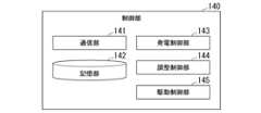
制御部140は、エネルギー保存装置100を制御する機能を有する。例えば、制御部140は、所定条件または所定の信号により錘180を上昇または下降させる制御を行う。図2は、制御部140の機能構成の一例を示す図である。制御部140は、例えば、通信部141と、記憶部142と、発電制御部143と、調整制御部144と、駆動制御部145とを備える。発電制御部143と、調整制御部144と、駆動制御部145とは、例えば、CPU(Central Processing Unit)等のハードウェアプロセッサがプログラム(ソフトウェア)を実行することにより実現される。これらの構成要素のうち一部または全部は、LSI(Large Scale Integration)やASIC(Application Specific Integrated Circuit)、FPGA(Field-Programmable Gate Array)、GPU(Graphics Processing Unit)等のハードウェア(回路部;circuitryを含む)によって実現されてもよいし、ソフトウェアとハードウェアの協働によって実現されてもよい。プログラムは、予めHDD(Hard Disk Drive)やフラッシュメモリ等の記憶装置(非一過性の記憶媒体を備える記憶装置)に格納されていてもよいし、DVDやCD-ROM等の着脱可能な記憶媒体(非一過性の記憶媒体)に格納されており、記憶媒体がドライブ装置に装着されることでインストールされてもよい。 The
通信部141は、例えば、支持部110、速度調整部120、モータ130と通信する通信インターフェースである。また、通信部141は、外部装置と通信を行ってもよい。外部装置とは、例えば洋上風力発電設備や海流発電設備等の他の発電設備であってもよく、エネルギー保存装置100や他の発電設備を管理する管理サーバであってもよい。 The
記憶部142は、上記の各種記憶装置により実現される。或いは、記憶部142は、SSD(Solid State Drive)、EEPROM(Electrically Erasable Programmable Read Only Memory)、ROM(Read Only Memory)、またはRAM(Random Access Memory)等により実現されてもよい。記憶部142には、例えば、制御部140が実行するプログラムや設定情報、その他各種情報が格納される。 The
発電制御部143は、第1の所定条件を満たす場合に錘180を下降させて発電を行う。第1の所定条件とは、例えば外部の発電設備が電力不足となり、不足分の電力を発電する必要が生じた場合である。また、発電制御部143は、第1の所定条件を満たすか否かを判定することに代えて、外部装置から錘180の下降または発電を指示する所定の信号を受け付けた場合に、信号に対応する処理を実行してもよい。 The power
発電制御部143は、発電する場合には、錘180を海底に落下させ、落下中の回転体160を正方向に回転させる(正回転させる)ことにより、回転体160の回転軸162に連結したモータ130によって発電させる。 When generating power, the power
調整制御部144は、速度調整部120により錘180の落下速度が一定速度で等速に落下するように回転体160の回転速度を制御する。等速に落下させることにより、安定した電力量を発電させることができる。また、調整制御部144は、必要な電力量以上の余剰電力が発電されないように錘180を落下途中で停止させる制御を行ってもよい。 The
駆動制御部145は、第2の所定条件を満たす場合に、海底に落下した錘180を上昇させる制御を行う。第2の所定条件とは、例えば、錘180を引き上げるだけでの余剰電力がある場合や、夜間等の電力の使用料金が安い場合である。なお、駆動制御部145は、第2所定条件を満たすか否かを判定することに代えて、外部装置から錘180の上昇(引き上げ)を指示する所定の信号を受け付けた場合に、信号に対応する処理を実行してもよい。また、駆動制御部145は、錘180を引き上げる場合には、モータ130を駆動させて回転体160を正方向とは逆方向に回転(逆回転)させ、ロープ170を巻き取る制御を実行する。 The
図1の例において、錘180を回転体160の回転軸162の位置から落下させる場合、回転軸162の位置(高さ)から海底までの距離D1を位置エネルギーとして持つことができるため、海底までの錘180の移動によって位置エネルギーを回転体160の運動エネルギーに変換することができ、回転体160の回転動作によってモータ130によって発電することができる。また、エネルギー保存装置100は、洋上で浮いているため、建物等の高い位置に設置させる必要がなく、重量制約が小さくなる。 In the example of FIG. 1, when the
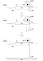
次に、図1に示す実施形態におけるエネルギー保存と発電の仕組みについて図を用いて説明する。図3は、エネルギー保存装置100におけるエネルギー保存と発電の仕組みについて説明するための図である。なお、図3の例では、錘180の位置エネルギーの変化に伴い回転体160を回転させて運転エネルギーに変換される様子を概略的に示している。また、図3の例において、時刻T11が最も早く、時刻T12、T13の順に遅くなっているものとする。 Next, the mechanism of energy storage and power generation in the embodiment shown in FIG. 1 will be explained using diagrams. FIG. 3 is a diagram for explaining the mechanism of energy storage and power generation in the
時刻T11では、例えば、外部からの電力(または動力)によって、回転体160を逆回転させてロープ170を巻き取ることで錘180を海面付近まで引き上げている。時刻T1において、位置エネルギーが最大であるものとする。このときの電力は、余剰の再生エネルギー電力でもよく、後述するようにエネルギー保存装置100に併設された洋上風力発電設備や太陽光発電設備、海流発電設備等の他の電力設備の電力であってもよい。また、時刻T1において錘180を引き上げた後、浮きを取り付けたり、回転軸162にラチェット機構を設けて発電時以外で正回転しないように制御することで、錘180を海面付近に固定させる。 At time T11, for example, the
時刻T12は、電力不足等による電力必要時に錘180を海底に向けて落下させ、回転軸162と連結したモータ130で発電させている。海中に錘180を落下させることで、錘180の位置エネルギーを回転体160の運動エネルギーに変換させる。時刻T13は、錘180が海底まで落下した状態を示している。この状態では回転体160の回転が停止するため、発電されない状態となる。 At time T12, when electric power is required due to a power shortage or the like, the
なお、錘180は、海中に入れるため、腐食しない金属または腐食しにくい金属であって、且つ、所定の重さを有する必要がある。所定の重さとは、少なくとも海水+αの重さである。αは、例えば、モータ130(発電部)や回転体160の動き出しの抵抗力を超える重量と海水中の抵抗を超える重量とを加算した重さである。また、αは、例えば、モータ130や回転体160の動き始め分の初速に対するエネルギーが別途与えられる場合に、動いているモータ130や回転体160を回し続けるのに必要な抵抗を超える重量と海水中の抵抗を超える重量とを加算した重さであってもよい。海水中の抵抗とは、例えば、海流等の影響が含まれてよい。 Note that since the
また、錘180の形状については、図1の例に限定されるものではなく、例えば中性浮力を利用可能な形状(例えば錘の内部を空洞にして海水を出し入れさせる形状)にしてもよい。 Further, the shape of the
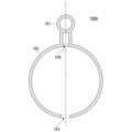
図4は、実施形態に適用される他の錘の一例を示す図である。図4は、他の錘180Aの垂直方向の断面図の一例を示す図である。錘180Aは、例えば、アイボルト181と、本体部182と、下部開口部183と、上部開口部184とを備える。図4の例では、本体部182の底部に下部開口部183が1つ設けられ、本体部182の天部に上部開口部184が1つ設けられているが、下部開口部183および上部開口部184のそれぞれは、複数の位置に設けられてもよい。 FIG. 4 is a diagram showing an example of another weight applied to the embodiment. FIG. 4 is a diagram showing an example of a vertical cross-sectional view of another
アイボルト181は、頭部がリング状になっており、ロープ170の端部を結ぶために利用される。本体部182は、内部に空間部(空洞)を有する形状の中空錘である。空間部は、水分(海水等の液体)が充填可能である。下部開口部183および上部開口部184は、水分を給脱可能な開口部である。下部開口部183は、錘180を海中に入れたときに海水が本体内部に注入される孔である。上部開口部184は、下部開口部183から海水が注入されることで、本体内部の空気を排出させる孔である。また逆に錘180を海中から空中に出した場合には、下部開口部183は、錘180内部の海水を排出する孔となり、上部開口部184は、本体内部に空気を注入する孔となる。 The
図5は、図4に示す錘180Aを落下させた様子について説明するための図である。図5では、錘180Aの本体内部に海水が注入される様子を簡略的に示している。また、図5において、時刻T21が最も早く、時刻T22、T23の順に遅くなっているものとする。 FIG. 5 is a diagram for explaining how the
時刻T21は、海中に錘180を落とした時点の状況を示している。海中に錘180を落とすことで、次第に下部開口部183から海水が錘180Aの内部に注入され、注入される海水量に伴って上部開口部184から空気が排出される(時刻T22)。そして時刻T23において、海水によって錘内部が満水状態(空気が完全に抜けた状態)になる。これにより、単に空洞のない球体の錘よりも海水との表面積が大きくなるため、海水による抵抗を大きく受けるため、錘180Aの落下速度をある程度抑制することができる。このように、落下速度に応じて錘の形状を調整することで、安定した落下速度に調整し易くすることができる。 Time T21 indicates the situation at the time when the
なお、上述した実施形態のエネルギー保存装置100は、例えば、風力発電や海流発電等の既存の発電設備から所定距離以内に設置(併設)されてよい。例えば、エネルギー保存装置100が風力によるプロペラの回転により発電する風力発電設備に併設される場合、回転体160を風力発電のプロペラの回転軸に物理的に接続したり、風力発電設備の発電部や送電系統を流用するように電力的に接続する構成にしてもよい。 Note that the
図6は、他の発電設備付近に設置されるエネルギー保存装置100について説明するための図である。なお、図6の例では、他の発電設備の一例として風力発電設備200を示している。風力発電設備200は、例えば、風の運動エネルギーを風車(風力タービン)によって回転エネルギーに変換し、そのエネルギーを発電部に出力することで電力(電気エネルギー)に変換する。 FIG. 6 is a diagram for explaining an
図6の例において、風力発電設備200は、浮体10に設けた基礎202上にタワー204を設置し、タワー204の上部に複数のプロペラ(ブレード)206が回転軸208を中心に回転するように設けられている。また、風力発電設備200は、例えば、回転軸208の回転数を発電に必要な回数まで増速する増速機210と、回転軸208の回転を停止または減速させるブレーキ装置212と、回転エネルギーを電力に変換する発電機(発電部の一例)214とを備える。また、図6の例では、風力発電設備200の発電機214によって発電された電力を需要者に供給するための送電系統PGが設けられている。また、エネルギー保存装置100の通信部141は、風力発電設備200と通信可能な状態で接続される。 In the example of FIG. 6, the wind
ここで、エネルギー保存装置100と風力発電設備200とが併設されている場合のエネルギーの供給について説明する。図6の例において、エネルギー保存装置100の制御部140は、風力発電設備200と通信を行い、外部から要求された必要電力需要量と風力発電設備200で発電可能な電力量とを取得し、必要電力需要量から発電可能電力量を減算して不足分の電力量があるか否かを判定する。そして、不足分の電力量がある場合に、制御部140は、錘180を落下させて発電する制御を行う。なお、制御部140は、風力発電設備200から直接不足電力量に関する情報を受信した場合や、発電指示を受信した場合に、錘180を落下させて発電する制御を行ってもよい。また、制御部140は、例えば、天気予報や災害発生時等の情報、過去の統計情報等に基づいて将来における不足電力量を予測し、予測した不足電力量に基づく発電制御を行ってもよい。 Here, energy supply when the
また、図6の例において、エネルギー保存装置100は、風力発電設備200による発電時に使用される一部の構成と物理的または電気的に接続されてもよい。この場合、制御部140は、風力発電設備200が風力発電を行っていない場合に、回転体160の回転軸162を、クラッチ機構等を用いて発電機214に物理的に連結させる制御を行って、発電機214を用いて回転軸162の回転に基づく発電を行ってもよい。また、制御部140は、クラッチ機構等を用いてプロペラ206の回転軸208に回転体160を連結させて回転体160の回転によって回転軸208が回転するように制御してもよい。 Furthermore, in the example of FIG. 6, the
また、制御部140は、切り替え制御により、風力発電設備200の送電系統PGと電気的に接続して、モータ130により発電された電力を需要者に供給してもよい。このように、風力発電設備200の発電機214をモータ130の代わりに流用したり、風力発電設備200の送電系統PGを流用することで、エネルギー保存装置100の設備コストをより抑制することができる。 Further, the
また、制御部140は、錘180を引き上げる場合には、風力発電設備200により発電された電力を用いてもよい。実施形態では、例えば風力発電等における余剰電力を、その場で錘を引き上げるための別のエネルギーに変換して位置エネルギーとしてエネルギーを保存しておき、不足時に錘を海底に落下させて再度電気に変換することで、電力をバッテリ等に蓄電しておく必要がなく、電力を無駄なく有効に活用することができる。 Furthermore, when pulling up the
例えば、風力発電設備200や太陽光発電設備、海流発電設備等は、天候等の影響によって、その日の発電量が大きく異なるため、毎日安定した電力量を供給できない場合があった。そこで、実施形態のエネルギー保存装置100を併設させることで、不足分の電力はエネルギー保存装置100による電力で補間することができ、逆に天候によって多く作り過ぎた余剰電力は錘180を引き上げるための電力として有効利用することができる。更に、風力発電設備200や太陽光発電設備等の再生エネルギーの設備は、建物等がない洋上(水上)に設置されることが多いため、実施形態のエネルギー保存装置100との親和性が非常に高い。 For example, the wind
[処理フロー]
図7は、実施形態に係るエネルギー保存装置100において実行される処理の一例を示すフローチャートである。図7の例において、制御部140は、例えば、電力需要量を導出する(ステップS100)。なお、ステップS100の処理では、エネルギー保存装置100の個別の電力需要量に代えて(または加えて)、エネルギー保存装置100付近(所定距離以内)に設置された他の発電設備における電力需要量であってもよい。[Processing flow]
FIG. 7 is a flowchart illustrating an example of a process executed in the
次に、制御部140は、電力が不足しているか否かを判定する(ステップS102)。電力が不足していると判定した場合、制御部140は、錘180を海底に落下させて回転体160を正回転させ(ステップS104)、回転体160の回転エネルギーを電気エネルギーに変換して発電を行う(ステップS106)。次に、制御部140は、発電した電力を、送電系統等を介して電力需要者に供給する(ステップS108)。 Next, the
また、ステップS102において、電力が不足していないと判定した場合、制御部140は、錘180が海底に落下した状態であるか否かを判定する(ステップS110)。錘180が海底に落下した状態であると判定した場合、既存の余剰電力や外部から取得した余剰電力等を利用して回転体160を逆回転させて錘180を引き上げる(ステップS112)。これにより、余剰電力を有効に活用することができる。また、ステップS110の処理において、錘180が落下した状態でないと判定した場合、本フローチャートの処理は、終了する。 If it is determined in step S102 that there is no shortage of power, the
<変形例>
次に、変形例について説明する。実施形態におけるエネルギー保存装置100は、例えば、錘と回転体との組を複数備え、制御部140は、複数の錘のうち一以上の錘を順次下降させて発電制御を行う。この場合、制御部140は、必要な電力量に応じて落下させる錘の数を調整してもよい。<Modified example>
Next, a modification will be explained. The
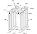
図8は、エネルギー保存装置100の変形例を示す図である。なお、図8の例では、エネルギー保存装置100が風力発電設備200付近に設けられているものとし、更に、エネルギー保存装置100のうち、特に回転体160と、回転軸162と、錘180との関係のみを概略的に示すものとする。 FIG. 8 is a diagram showing a modification of the
変形例では、回転軸162にそれぞれが個別で回転する複数の回転体160を設け、各回転体160には、回転によって繰り出しまたは巻き取られるロープ170を有し、それぞれのロープ170の先には、錘180が設けられている。なお、図8の例では、2つの回転軸162A、162Bに、それぞれ複数の回転体160-a1~160-a12、160-b1~160-b12が設けられており、それぞれの回転体に対応付けてロープ170と錘180-a1~180-a12、180-b1~180-b12が設けられている。また、回転軸162A、162Bに並列された複数の回転体のうち、一つの回転体の回転によって回転軸は回転するが、他の回転体は回転しないような機構を有している。 In a modified example, a plurality of
制御部140は、複数の回転体を順次落下させることで、回転軸162A、162Bを長時間回転させることができるため、必要な電力量が大きい場合であっても発電させることができる。 Since the
例えば、図8に示す変形例において、制御部140は、風力発電設備200に対して必要な電力需要量と風力発電設備200の発電可能電力量とから不足電力量を取得し、取得した不足電力量に対応して、海底に落下させる錘180の数を決定する。この場合、制御部140は、一つの錘180を落下させることによって得られる発電量を管理しておくことで、不足電力量に応じて落下させる錘の数を決定することができる。また、制御部140は、決定した数の錘180を順次落下させて発電する制御を行う。なお、並列した錘180を落下させた場合に海流等の影響により海中でロープ170が絡まることがないように、制御部140は、錘180ごとに所定間隔のオフセットを設けて設置されていてもよく、落下させる場合に並列に設置された錘180のうち、所定間隔が空いた位置の錘180を落下させてもよい。 For example, in the modification shown in FIG. 8, the
また、図8に示すように二つの回転軸162A、162Bを有する場合に、エネルギー保存装置100は、それぞれの軸の回転によってモータ130による発電が可能となるように回転軸162A、162Bとの連結機構が設けられていてもよい。 Furthermore, when having two
図9は、複数の回転軸との連結機構について説明するための図である。図9の例では、モータ130に接続される回転軸162にギア(gear)164が設けられており、また、各回転軸162A、162Bのそれぞれにもギア164A、164Bが設けられている。また、図9の例では、図8に示す回転体160-a1~160-a12、160-b1~160-b12を、回転体160-a、160-bと簡略化して示している。例えば、制御部140は、落下させる錘の位置に応じて、モータ130と連結させる回転軸を特定する。具体的には、制御部140は、錘の落下によって回転する回転軸をモータ130と連結させる回転軸として特定する。そして、制御部140は、特定した回転軸に設けられたギア164Aまたは164Bと、モータ130と連結した回転軸162のギア164とが噛み合うように切り替え制御を行い、お互いのギアを介して錘による回転軸の回転エネルギーをモータ130に伝達させる。これにより、複数の回転軸が存在する場合であってもモータ130を流用して使用することができる。 FIG. 9 is a diagram for explaining a connection mechanism with a plurality of rotating shafts. In the example of FIG. 9, a
なお、図8に示すように複数の回転軸を有する場合には、回転軸ごとに発電を行うモータが設けられていてもよい。また、変形例に示す各錘は、同じ重さや形状のものでもよく、異なる重さや形状であってもよい。また、図8の例では、回転体160を有する支持部110を、複数の錘を独立して上昇及び下降可能に支持するように複数設けて、複数の支持部のうち、不足電力量に対応する数の支持部を回転軸162に対して選択的に接続して、回転軸162を回転させるような切替機構を設けていてもよい。 Note that in the case of having a plurality of rotating shafts as shown in FIG. 8, a motor that generates power may be provided for each rotating shaft. Furthermore, the weights shown in the modified examples may have the same weight and shape, or may have different weights and shapes. In the example of FIG. 8, a plurality of
[処理フロー]
図10は、変形例におけるエネルギー保存装置によって実行される処理の一例を示すフローチャートである。図10では、図7に示すステップS100~S112の処理と比較して、ステップS104、S110の処理に代えて、ステップS120~S124の処理を有する点で相違する。したがって、以下では、主にステップS120~S124の処理を中心として説明する。[Processing flow]
FIG. 10 is a flowchart illustrating an example of processing performed by the energy storage device in the modified example. 10 differs from the processing in steps S100 to S112 shown in FIG. 7 in that the processing in steps S120 to S124 is included instead of the processing in steps S104 and S110. Therefore, the following description will mainly focus on the processing in steps S120 to S124.
ステップS102の処理において、電力が不足していると判定した場合、制御部140は、不足電力量に応じて海底に落下させる錘180の数を決定する(ステップS120)。例えば、次に、制御部140は、決定した数の錘を順番に海底に落下させて回転を正回転させ(ステップS122)。回転体の運動エネルギーをモータ130によって電気エネルギーに変換して発電を行う(ステップS106)。 In the process of step S102, when it is determined that the power is insufficient, the
また、ステップS102の処理において、電力が不足していないと判定した場合、制御部140は、少なくとも一つの錘180が落下した状態であるか否かを判定し(ステップS124)、少なくとも一つの錘180が落下した状態であると判定した場合に、余剰電力等を利用して回転体を逆回転させて錘を引き上げる制御を行う(ステップS122)。 Further, in the process of step S102, if it is determined that there is no shortage of power, the
以上の通り説明した実施形態によれば、エネルギー保存装置100において回転体160の回転動作に伴い錘を上昇及び下降可能に支持する支持部110と、所定条件または所定の信号により錘180を上昇または下降させる制御部140と、錘180が下降する際の回転体160の回転動作によって発電するモータ(発電部の一例)130と、を備え、支持部110は、錘180が水中を下降するように水上または水面から所定距離以内の位置に設けられることにより、構造的なスペースやコストをより抑制して電力を供給することができる。そして、延いてはエネルギーの効率化に寄与することができる。 According to the embodiment described above, in the
例えば、実施形態によれば、例えば、海の海面や、海底の長さを利用することで、位置エネルギーを確保するために上下方向の構造物を作ることなく、自然の地形を有効活用して発電することができる。また、実施形態によれば、洋上発電所に錘と回転軸を設置し、余剰電力にて錘を上昇させ、電力不足時に錘を海中に落下させることで、位置エネルギーを回転エネルギーに変換し、発電機を回すことで電力に変換することができる。また、実施形態によれば、錘の重さを海水同等+αの質量にすることで、中性浮力により等速運動で海中に移動させ、発電機の回転数を一定に保ちやすくすることができる。そのため、安定した電力を生成することができると共に、速度調整部等の構成への負荷を軽減させることができる。 For example, according to the embodiment, by making use of the sea surface or the length of the ocean floor, natural topography can be effectively utilized without creating vertical structures to secure potential energy. It can generate electricity. Further, according to the embodiment, a weight and a rotating shaft are installed in an offshore power plant, the weight is raised using surplus power, and the weight is dropped into the sea when there is a power shortage, thereby converting potential energy into rotational energy. It can be converted into electricity by turning a generator. Further, according to the embodiment, by making the weight of the weight equal to seawater + α, it is possible to move the weight into the sea with uniform motion due to neutral buoyancy, making it easier to maintain the rotational speed of the generator constant. . Therefore, stable electric power can be generated, and the load on the configuration such as the speed adjustment section can be reduced.
上記説明した実施形態は、以下のように表現することができる。
プログラムを記憶した記憶装置と、
ハードウェアプロセッサと、を備え、
前記ハードウェアプロセッサが前記プログラムを実行することにより、
支持部により回転体の回転動作に伴い錘を上昇及び下降可能に支持し、
所定条件または所定の信号により前記錘を上昇または下降させ、
前記錘が下降する際の前記回転体の回転動作によって発電し、
前記支持部は、前記錘が水中を下降するように水上または水面から所定距離以内の位置に設けられる、
ように構成されている、エネルギー保存装置。The embodiment described above can be expressed as follows.
a storage device that stores the program;
comprising a hardware processor;
By the hardware processor executing the program,
The support part supports the weight so that it can rise and fall as the rotating body rotates,
raising or lowering the weight according to predetermined conditions or a predetermined signal;
Generating electricity by the rotational movement of the rotating body when the weight descends,
The support part is provided at a position above the water or within a predetermined distance from the water surface so that the weight descends in the water.
An energy storage device configured as follows.
以上、本発明を実施するための形態について実施形態を用いて説明したが、本発明はこうした実施形態に何等限定されるものではなく、本発明の要旨を逸脱しない範囲内において種々の変形及び置換を加えることができる。 Although the mode for implementing the present invention has been described above using embodiments, the present invention is not limited to these embodiments in any way, and various modifications and substitutions can be made without departing from the gist of the present invention. can be added.
10…浮体、100…エネルギー保存装置、110…支持部、120…速度調整部、130…モータ、140…制御部、141…通信部、142…記憶部、143…発電制御部、144…調整制御部、145…駆動制御部、160…回転体、162…回転軸、170…ロープ、180…錘 DESCRIPTION OF
Claims (7)
Translated fromJapanese所定条件または所定の信号により前記錘を上昇または下降させる制御部と、
前記錘が下降する際の前記回転体の回転動作によって発電する発電部と、を備え、
前記支持部は、前記錘が水中を下降するように水上または水面から所定距離以内の位置に設けられる、
エネルギー保存装置。a support part that supports the weight so that it can rise and fall as the rotating body rotates;
a control unit that raises or lowers the weight according to predetermined conditions or a predetermined signal;
a power generation unit that generates power by the rotational movement of the rotating body when the weight descends;
The support part is provided at a position above the water or within a predetermined distance from the water surface so that the weight descends in the water.
Energy storage device.
請求項1に記載のエネルギー保存装置。The weight includes a space that can be filled with moisture and an opening that can supply and remove the moisture.
An energy storage device according to claim 1.
ことを特徴とする請求項2に記載のエネルギー保存装置。The openings are provided at a plurality of positions including a bottom and a top of the weight,
3. The energy storage device according to claim 2.
前記制御部は、複数の錘のうち一以上の錘を順次下降させて発電制御を行う、
請求項1に記載のエネルギー保存装置。comprising a plurality of pairs of the weight and the rotating body,
The control unit performs power generation control by sequentially lowering one or more of the plurality of weights.
An energy storage device according to claim 1.
請求項4に記載のエネルギー保存装置。The control unit derives a power shortage based on the power demand, and determines the number of weights to be lowered into the water among the plurality of weights according to the derived power shortage.
Energy storage device according to claim 4.
請求項1に記載のエネルギー保存装置。Installed within a predetermined distance from wind power generation equipment that generates electricity by rotating a propeller caused by wind power, and physically or electrically connected to a part of the structure used when generating electricity by the wind power generation equipment.
An energy storage device according to claim 1.
支持部により回転体の回転動作に伴い錘を上昇及び下降可能に支持し、
所定条件または所定の信号により前記錘を上昇または下降させ、
前記錘が下降する際の前記回転体の回転動作によって発電し、
前記支持部は、前記錘が水中を下降するように水上または水面から所定距離以内の位置に設けられる、
エネルギー保存方法。The energy storage computer
The support part supports the weight so that it can rise and fall as the rotating body rotates,
raising or lowering the weight according to predetermined conditions or a predetermined signal;
Generating electricity by the rotational movement of the rotating body when the weight descends,
The support part is provided at a position above the water or within a predetermined distance from the water surface so that the weight descends in the water.
Energy conservation methods.
Priority Applications (1)
| Application Number | Priority Date | Filing Date | Title |
|---|---|---|---|
| JP2022072342AJP2023161787A (en) | 2022-04-26 | 2022-04-26 | Energy storage device, and energy storage method |
Applications Claiming Priority (1)
| Application Number | Priority Date | Filing Date | Title |
|---|---|---|---|
| JP2022072342AJP2023161787A (en) | 2022-04-26 | 2022-04-26 | Energy storage device, and energy storage method |
Publications (1)
| Publication Number | Publication Date |
|---|---|
| JP2023161787Atrue JP2023161787A (en) | 2023-11-08 |
Family
ID=88650506
Family Applications (1)
| Application Number | Title | Priority Date | Filing Date |
|---|---|---|---|
| JP2022072342APendingJP2023161787A (en) | 2022-04-26 | 2022-04-26 | Energy storage device, and energy storage method |
Country Status (1)
| Country | Link |
|---|---|
| JP (1) | JP2023161787A (en) |
Citations (5)
| Publication number | Priority date | Publication date | Assignee | Title |
|---|---|---|---|---|
| JPH06147097A (en)* | 1992-11-09 | 1994-05-27 | Yoneda Seisakusho:Yugen | Gravity applied generating set |
| JP2011511212A (en)* | 2008-02-06 | 2011-04-07 | ローンチポイント テクノロジーズ, インコーポレイテッド | System and method for storing energy |
| JP2014031740A (en)* | 2012-08-02 | 2014-02-20 | Akimori Taniguchi | Method for converting kinetic energy of natural sea waves into rotational motion through drooping phenomenon of counterbalancing weight and generating power by utilizing gravity of earth |
| JP2017505880A (en)* | 2014-01-28 | 2017-02-23 | スティーブンズ, クリストフSTEVENS, Christophe | System for storing and generating electrical energy in water environment |
| JP2020197205A (en)* | 2019-06-04 | 2020-12-10 | 優 後藤 | On-demand weight power generation system |
- 2022
- 2022-04-26JPJP2022072342Apatent/JP2023161787A/enactivePending
Patent Citations (5)
| Publication number | Priority date | Publication date | Assignee | Title |
|---|---|---|---|---|
| JPH06147097A (en)* | 1992-11-09 | 1994-05-27 | Yoneda Seisakusho:Yugen | Gravity applied generating set |
| JP2011511212A (en)* | 2008-02-06 | 2011-04-07 | ローンチポイント テクノロジーズ, インコーポレイテッド | System and method for storing energy |
| JP2014031740A (en)* | 2012-08-02 | 2014-02-20 | Akimori Taniguchi | Method for converting kinetic energy of natural sea waves into rotational motion through drooping phenomenon of counterbalancing weight and generating power by utilizing gravity of earth |
| JP2017505880A (en)* | 2014-01-28 | 2017-02-23 | スティーブンズ, クリストフSTEVENS, Christophe | System for storing and generating electrical energy in water environment |
| JP2020197205A (en)* | 2019-06-04 | 2020-12-10 | 優 後藤 | On-demand weight power generation system |
Similar Documents
| Publication | Publication Date | Title |
|---|---|---|
| EP2461028A2 (en) | A floating offshore wind farm, a floating offshore wind turbine and a method for positioning a floating offshore wind turbine | |
| JP4279148B2 (en) | Wind turbine | |
| EP2333314B1 (en) | Systems for assembling an offshore support system for use with a wind turbine | |
| EP2080899A1 (en) | An offshore wind turbine with a rotor integrated with a floating and rotating foundation | |
| EP2721288A2 (en) | Alternative mechanical and electrical concept for offshore wind farms | |
| CN116201690A (en) | Power generation device with gravity energy storage device and power generation method | |
| CN112969849B (en) | High-efficiency wind energy converter without gearbox or multi-pole generator | |
| Fulton et al. | Design of a semi-submersible platform for a 5MW wind turbine | |
| JP2023161787A (en) | Energy storage device, and energy storage method | |
| KR101179682B1 (en) | Floating offshore wind power generation plant | |
| CN112384693A (en) | Method of operating a floating offshore wind turbine | |
| JP2023551350A (en) | floating offshore structure | |
| CN118137536A (en) | A gravity energy storage device and power generation system based on abandoned oil, gas and water wells | |
| CN117404253A (en) | Vertical shaft floating type offshore wind power generation equipment and working control method thereof | |
| WO2015129015A1 (en) | Wind farm | |
| CN111433454A (en) | Power ramp rate control | |
| JP2020094521A (en) | Wind power generating system using air-staying kite-type structure | |
| JP6320738B2 (en) | Wind power generation facility and maintenance method of wind power generation facility | |
| CN103527392B (en) | Wave gushes vertical generating device | |
| WO2021193745A1 (en) | Sink-and-float-type solar power generation device | |
| CN117864329B (en) | A system integrating active control and power generation functions of floating wind turbine structure | |
| JP2024093860A (en) | Power storage system and power generation system | |
| Li et al. | Offshore wind turbines and their installation | |
| WO2025136363A1 (en) | Systems and methods for reducing loads induced in a floating offshore structure | |
| Ritschel | 1 Technology of Offshore Wind Energy Turbines: Current Status and Developments |
Legal Events
| Date | Code | Title | Description |
|---|---|---|---|
| A621 | Written request for application examination | Free format text:JAPANESE INTERMEDIATE CODE: A621 Effective date:20241127 | |
| A977 | Report on retrieval | Free format text:JAPANESE INTERMEDIATE CODE: A971007 Effective date:20250813 | |
| A131 | Notification of reasons for refusal | Free format text:JAPANESE INTERMEDIATE CODE: A131 Effective date:20250819 |