JP2023160756A - Electrosurgical system and method for determining electrode type of neutral electrode - Google Patents
Electrosurgical system and method for determining electrode type of neutral electrodeDownload PDFInfo
- Publication number
- JP2023160756A JP2023160756AJP2023063845AJP2023063845AJP2023160756AJP 2023160756 AJP2023160756 AJP 2023160756AJP 2023063845 AJP2023063845 AJP 2023063845AJP 2023063845 AJP2023063845 AJP 2023063845AJP 2023160756 AJP2023160756 AJP 2023160756A
- Authority
- JP
- Japan
- Prior art keywords
- electrode
- neutral
- impedance
- electrosurgical system
- section
- Prior art date
- Legal status (The legal status is an assumption and is not a legal conclusion. Google has not performed a legal analysis and makes no representation as to the accuracy of the status listed.)
- Pending
Links
Images


Classifications
- A—HUMAN NECESSITIES
- A61—MEDICAL OR VETERINARY SCIENCE; HYGIENE
- A61B—DIAGNOSIS; SURGERY; IDENTIFICATION
- A61B18/00—Surgical instruments, devices or methods for transferring non-mechanical forms of energy to or from the body
- A—HUMAN NECESSITIES
- A61—MEDICAL OR VETERINARY SCIENCE; HYGIENE
- A61B—DIAGNOSIS; SURGERY; IDENTIFICATION
- A61B18/00—Surgical instruments, devices or methods for transferring non-mechanical forms of energy to or from the body
- A61B18/04—Surgical instruments, devices or methods for transferring non-mechanical forms of energy to or from the body by heating
- A61B18/12—Surgical instruments, devices or methods for transferring non-mechanical forms of energy to or from the body by heating by passing a current through the tissue to be heated, e.g. high-frequency current
- A61B18/1206—Generators therefor
- A—HUMAN NECESSITIES
- A61—MEDICAL OR VETERINARY SCIENCE; HYGIENE
- A61B—DIAGNOSIS; SURGERY; IDENTIFICATION
- A61B18/00—Surgical instruments, devices or methods for transferring non-mechanical forms of energy to or from the body
- A61B18/04—Surgical instruments, devices or methods for transferring non-mechanical forms of energy to or from the body by heating
- A61B18/12—Surgical instruments, devices or methods for transferring non-mechanical forms of energy to or from the body by heating by passing a current through the tissue to be heated, e.g. high-frequency current
- A61B18/14—Probes or electrodes therefor
- A61B18/16—Indifferent or passive electrodes for grounding
- A—HUMAN NECESSITIES
- A61—MEDICAL OR VETERINARY SCIENCE; HYGIENE
- A61B—DIAGNOSIS; SURGERY; IDENTIFICATION
- A61B18/00—Surgical instruments, devices or methods for transferring non-mechanical forms of energy to or from the body
- A61B18/04—Surgical instruments, devices or methods for transferring non-mechanical forms of energy to or from the body by heating
- A61B18/12—Surgical instruments, devices or methods for transferring non-mechanical forms of energy to or from the body by heating by passing a current through the tissue to be heated, e.g. high-frequency current
- A61B18/1206—Generators therefor
- A61B18/1233—Generators therefor with circuits for assuring patient safety
- A—HUMAN NECESSITIES
- A61—MEDICAL OR VETERINARY SCIENCE; HYGIENE
- A61B—DIAGNOSIS; SURGERY; IDENTIFICATION
- A61B18/00—Surgical instruments, devices or methods for transferring non-mechanical forms of energy to or from the body
- A61B18/04—Surgical instruments, devices or methods for transferring non-mechanical forms of energy to or from the body by heating
- A61B18/12—Surgical instruments, devices or methods for transferring non-mechanical forms of energy to or from the body by heating by passing a current through the tissue to be heated, e.g. high-frequency current
- A61B18/14—Probes or electrodes therefor
- A—HUMAN NECESSITIES
- A61—MEDICAL OR VETERINARY SCIENCE; HYGIENE
- A61B—DIAGNOSIS; SURGERY; IDENTIFICATION
- A61B17/00—Surgical instruments, devices or methods
- A61B2017/00017—Electrical control of surgical instruments
- A—HUMAN NECESSITIES
- A61—MEDICAL OR VETERINARY SCIENCE; HYGIENE
- A61B—DIAGNOSIS; SURGERY; IDENTIFICATION
- A61B17/00—Surgical instruments, devices or methods
- A61B2017/00017—Electrical control of surgical instruments
- A61B2017/00022—Sensing or detecting at the treatment site
- A61B2017/00026—Conductivity or impedance, e.g. of tissue
- A—HUMAN NECESSITIES
- A61—MEDICAL OR VETERINARY SCIENCE; HYGIENE
- A61B—DIAGNOSIS; SURGERY; IDENTIFICATION
- A61B18/00—Surgical instruments, devices or methods for transferring non-mechanical forms of energy to or from the body
- A61B2018/00571—Surgical instruments, devices or methods for transferring non-mechanical forms of energy to or from the body for achieving a particular surgical effect
- A61B2018/00577—Ablation
- A—HUMAN NECESSITIES
- A61—MEDICAL OR VETERINARY SCIENCE; HYGIENE
- A61B—DIAGNOSIS; SURGERY; IDENTIFICATION
- A61B18/00—Surgical instruments, devices or methods for transferring non-mechanical forms of energy to or from the body
- A61B2018/00571—Surgical instruments, devices or methods for transferring non-mechanical forms of energy to or from the body for achieving a particular surgical effect
- A61B2018/00589—Coagulation
- A—HUMAN NECESSITIES
- A61—MEDICAL OR VETERINARY SCIENCE; HYGIENE
- A61B—DIAGNOSIS; SURGERY; IDENTIFICATION
- A61B18/00—Surgical instruments, devices or methods for transferring non-mechanical forms of energy to or from the body
- A61B2018/00571—Surgical instruments, devices or methods for transferring non-mechanical forms of energy to or from the body for achieving a particular surgical effect
- A61B2018/00601—Cutting
- A—HUMAN NECESSITIES
- A61—MEDICAL OR VETERINARY SCIENCE; HYGIENE
- A61B—DIAGNOSIS; SURGERY; IDENTIFICATION
- A61B18/00—Surgical instruments, devices or methods for transferring non-mechanical forms of energy to or from the body
- A61B2018/00636—Sensing and controlling the application of energy
- A61B2018/00642—Sensing and controlling the application of energy with feedback, i.e. closed loop control
- A61B2018/00648—Sensing and controlling the application of energy with feedback, i.e. closed loop control using more than one sensed parameter
- A—HUMAN NECESSITIES
- A61—MEDICAL OR VETERINARY SCIENCE; HYGIENE
- A61B—DIAGNOSIS; SURGERY; IDENTIFICATION
- A61B18/00—Surgical instruments, devices or methods for transferring non-mechanical forms of energy to or from the body
- A61B2018/00636—Sensing and controlling the application of energy
- A61B2018/00684—Sensing and controlling the application of energy using lookup tables
- A—HUMAN NECESSITIES
- A61—MEDICAL OR VETERINARY SCIENCE; HYGIENE
- A61B—DIAGNOSIS; SURGERY; IDENTIFICATION
- A61B18/00—Surgical instruments, devices or methods for transferring non-mechanical forms of energy to or from the body
- A61B2018/00636—Sensing and controlling the application of energy
- A61B2018/00696—Controlled or regulated parameters
- A61B2018/0072—Current
- A—HUMAN NECESSITIES
- A61—MEDICAL OR VETERINARY SCIENCE; HYGIENE
- A61B—DIAGNOSIS; SURGERY; IDENTIFICATION
- A61B18/00—Surgical instruments, devices or methods for transferring non-mechanical forms of energy to or from the body
- A61B2018/00636—Sensing and controlling the application of energy
- A61B2018/00696—Controlled or regulated parameters
- A61B2018/00767—Voltage
- A—HUMAN NECESSITIES
- A61—MEDICAL OR VETERINARY SCIENCE; HYGIENE
- A61B—DIAGNOSIS; SURGERY; IDENTIFICATION
- A61B18/00—Surgical instruments, devices or methods for transferring non-mechanical forms of energy to or from the body
- A61B2018/00636—Sensing and controlling the application of energy
- A61B2018/00773—Sensed parameters
- A61B2018/00869—Phase
- A—HUMAN NECESSITIES
- A61—MEDICAL OR VETERINARY SCIENCE; HYGIENE
- A61B—DIAGNOSIS; SURGERY; IDENTIFICATION
- A61B18/00—Surgical instruments, devices or methods for transferring non-mechanical forms of energy to or from the body
- A61B2018/00636—Sensing and controlling the application of energy
- A61B2018/00773—Sensed parameters
- A61B2018/00875—Resistance or impedance
- A—HUMAN NECESSITIES
- A61—MEDICAL OR VETERINARY SCIENCE; HYGIENE
- A61B—DIAGNOSIS; SURGERY; IDENTIFICATION
- A61B18/00—Surgical instruments, devices or methods for transferring non-mechanical forms of energy to or from the body
- A61B18/04—Surgical instruments, devices or methods for transferring non-mechanical forms of energy to or from the body by heating
- A61B18/12—Surgical instruments, devices or methods for transferring non-mechanical forms of energy to or from the body by heating by passing a current through the tissue to be heated, e.g. high-frequency current
- A61B18/1206—Generators therefor
- A61B2018/1246—Generators therefor characterised by the output polarity
- A61B2018/1253—Generators therefor characterised by the output polarity monopolar
- A—HUMAN NECESSITIES
- A61—MEDICAL OR VETERINARY SCIENCE; HYGIENE
- A61B—DIAGNOSIS; SURGERY; IDENTIFICATION
- A61B18/00—Surgical instruments, devices or methods for transferring non-mechanical forms of energy to or from the body
- A61B18/04—Surgical instruments, devices or methods for transferring non-mechanical forms of energy to or from the body by heating
- A61B18/12—Surgical instruments, devices or methods for transferring non-mechanical forms of energy to or from the body by heating by passing a current through the tissue to be heated, e.g. high-frequency current
- A61B18/1206—Generators therefor
- A61B2018/128—Generators therefor generating two or more frequencies
- A—HUMAN NECESSITIES
- A61—MEDICAL OR VETERINARY SCIENCE; HYGIENE
- A61B—DIAGNOSIS; SURGERY; IDENTIFICATION
- A61B18/00—Surgical instruments, devices or methods for transferring non-mechanical forms of energy to or from the body
- A61B18/04—Surgical instruments, devices or methods for transferring non-mechanical forms of energy to or from the body by heating
- A61B18/12—Surgical instruments, devices or methods for transferring non-mechanical forms of energy to or from the body by heating by passing a current through the tissue to be heated, e.g. high-frequency current
- A61B18/14—Probes or electrodes therefor
- A61B18/16—Indifferent or passive electrodes for grounding
- A61B2018/167—Passive electrodes capacitively coupled to the skin
Landscapes
- Health & Medical Sciences (AREA)
- Surgery (AREA)
- Life Sciences & Earth Sciences (AREA)
- Engineering & Computer Science (AREA)
- Biomedical Technology (AREA)
- Otolaryngology (AREA)
- Nuclear Medicine, Radiotherapy & Molecular Imaging (AREA)
- Heart & Thoracic Surgery (AREA)
- Medical Informatics (AREA)
- Molecular Biology (AREA)
- Animal Behavior & Ethology (AREA)
- General Health & Medical Sciences (AREA)
- Public Health (AREA)
- Veterinary Medicine (AREA)
- Plasma & Fusion (AREA)
- Physics & Mathematics (AREA)
- Surgical Instruments (AREA)
Abstract
Translated fromJapaneseDescription
Translated fromJapanese本発明は、中性電極の電極タイプを決定するための電気外科システムおよび方法に関する。電気外科システムは、特に、電気外科システムの供給装置に接続することができるか、または接続される単極器具および中性電極を有するシステムである。中性電極は、例えば接着接続によって、導電的に患者に取り付けられるように構成される。本方法は、本発明による電気外科システムを使用して実施することができる。電気外科システムは、特に、本発明による方法を実施するように構成することができる。 The present invention relates to an electrosurgical system and method for determining the electrode type of a neutral electrode. An electrosurgical system is, in particular, a system having a monopolar instrument and a neutral electrode that can be or is connected to a supply device of the electrosurgical system. The neutral electrode is configured to be electrically conductively attached to the patient, for example by an adhesive connection. The method can be performed using an electrosurgical system according to the invention. The electrosurgical system can be particularly configured to carry out the method according to the invention.
患者の治療中、電気外科システムでは、供給装置から器具の作用電極へ、そしてそこから供給装置に戻る電流回路を閉じる必要がある。この目的のために、単極器具では、中性電極として示すことができる追加の電極を患者に取り付けることができる。したがって、電流は、供給装置から作用電極に流れ、作用電極から患者に流れ、患者の組織を通って中性電極に流れ、そこから供給装置に戻ることができる。 During patient treatment, electrosurgical systems require closing of the current circuit from the delivery device to the working electrode of the instrument and from there back to the delivery device. For this purpose, in monopolar instruments, an additional electrode can be attached to the patient, which can be designated as a neutral electrode. Thus, current can flow from the delivery device to the working electrode, from the working electrode to the patient, through the patient's tissue to the neutral electrode, and from there back to the delivery device.
単極器具を有する電気外科システムでは、中性電極の異なる種類の電極または電極タイプを使用することができる。異なる電極タイプの中性電極は、患者と接触している異なるサイズの少なくとも1つの導電性電極セクションの表面積(接触面積)を含むことができる。中性電極の少なくとも1つの導電性電極セクションはまた、異なる電極タイプに対して長手方向および/または横方向に異なる幾何学的形状または寸法を有することができる。 In electrosurgical systems with monopolar instruments, different types or electrode types of neutral electrodes can be used. Neutral electrodes of different electrode types can include a surface area (contact area) of at least one conductive electrode section of different size in contact with the patient. The at least one conductive electrode section of the neutral electrode can also have different longitudinal and/or lateral geometries or dimensions for different electrode types.
電気外科システムの動作中に内因性の火傷を回避するために、中性電極での電流密度は高くなりすぎてはならない。 To avoid intrinsic burns during operation of the electrosurgical system, the current density at the neutral electrode should not be too high.
特許文献1は、中性電極インピーダンスに依存する医療装置の制御を記載している。インピーダンスは所定の閾値と比較され、電気外科システムまたは治療器具の動作は、中性電極のインピーダンスが所定の範囲内、例えば最大140オーム内にある場合にのみ可能にされる。そうすることで、中性電極が患者に正しく取り付けられているかどうか、および患者への十分に良好な電気的接続が存在するかどうかを試験することができる。 US Pat. No. 5,001,500 describes control of a medical device that relies on neutral electrode impedance. The impedance is compared to a predetermined threshold and operation of the electrosurgical system or treatment instrument is only allowed if the impedance of the neutral electrode is within a predetermined range, for example up to 140 ohms. By doing so, it is possible to test whether the neutral electrode is correctly attached to the patient and whether there is a sufficiently good electrical connection to the patient.
生体組織のインピーダンスの測定は、インピーダンス分光法の分野で知られている。インピーダンス分光法では、電気外科システムの電気外科器具によって治療される組織のタイプが区別される。例えば、特許文献2は、そのような方法を記載している。この器具により、試験信号が、異なる周波数において、治療される組織に印加され、測定されたインピーダンスに基づいて、組織が特徴付けられる。このようにして、異なる組織タイプの区別が可能である。同様の方法が、特許文献3にも記載されている。 Measuring the impedance of biological tissues is known in the field of impedance spectroscopy. Impedance spectroscopy distinguishes between the types of tissue treated by the electrosurgical instruments of an electrosurgical system. For example, U.S. Pat. No. 5,001,300 describes such a method. With this instrument, test signals are applied at different frequencies to the tissue to be treated and the tissue is characterized based on the measured impedance. In this way, a distinction between different tissue types is possible. A similar method is also described in
特許文献4から知られている方法では、電気パルスが患者の組織内に供給され、供給されたパルスの反射が検出される。反射に基づいて、健康な組織が、悪性組織とリアルタイムで区別される。 In the method known from US Pat. No. 5,300,300, electrical pulses are delivered into the tissue of a patient and the reflections of the delivered pulses are detected. Based on reflections, healthy tissue is distinguished from malignant tissue in real time.
測定ユニットを有する電気外科システムが、特許文献5に記載されている。そこでは、治療される組織のインピーダンス測定が、測定デバイスによって異なる周波数において実施される。測定信号は、測定デバイスによって組織に印加することができる。スイッチングデバイスは、組織の治療のための電圧と測定信号との間で切り替えるように機能する。測定信号によって、組織のインピーダンスが異なる周波数において決定される。 An electrosurgical system with a measuring unit is described in US Pat. There, impedance measurements of the tissue to be treated are performed at different frequencies by a measuring device. A measurement signal can be applied to the tissue by a measurement device. The switching device functions to switch between a voltage and a measurement signal for tissue treatment. The measurement signal determines the impedance of the tissue at different frequencies.
身体組織の局所組織タイプを決定するための方法およびそれぞれの電気外科システムが、特許文献6に記載されている。組織決定のために、測定信号(交流電圧または交流電流)が、組織内に結合される。測定信号の周波数は変化し得る。それに基づいて、インピーダンススペクトルを決定することができ、そこから組織タイプを順に導出することができる。 A method and a respective electrosurgical system for determining local tissue types of body tissues are described in US Pat. For tissue determination, a measurement signal (alternating voltage or alternating current) is coupled into the tissue. The frequency of the measurement signal may vary. Based thereon, an impedance spectrum can be determined, from which tissue types can in turn be derived.
本発明の目的は、中性電極の使用を改善し、特に中性電極を使用する際の安全性を高める電気外科システムおよび方法を提供することにあると考えることができる。 An object of the present invention can be considered to be to provide an electrosurgical system and method that improves the use of neutral electrodes and in particular increases safety when using neutral electrodes.
この目的は、請求項1の特徴を有する電気外科システム、ならびに請求項15の特徴を有する方法によって解決される。 This object is solved by an electrosurgical system with the features of
本発明による電気外科システムは、中性点接続部と、中性点接続部に接続された中性電極とを備える供給装置を備える。中性電極は、患者に導電的に接続されるように構成される。この目的のために、中性電極は、患者の皮膚に接着接続することができ、または他の方法で取り付けることができる。 The electrosurgical system according to the invention comprises a delivery device comprising a neutral connection and a neutral electrode connected to the neutral connection. The neutral electrode is configured to be electrically conductively connected to the patient. For this purpose, the neutral electrode can be adhesively connected or otherwise attached to the patient's skin.
供給装置は、少なくとも2つの異なる測定周波数において、交流測定信号を中性点接続部に印加するように構成することができる。測定信号は、交流電圧測定信号または交流電流測定信号とすることができる。例えば、測定信号は、正弦波または共正弦波形状、三角形形状、鋸歯形状または方形波形状を有することができる。 The supply device can be configured to apply an alternating current measurement signal to the neutral connection at at least two different measurement frequencies. The measurement signal can be an alternating voltage measurement signal or an alternating current measurement signal. For example, the measurement signal can have a sinusoidal or co-sinusoidal shape, a triangular shape, a sawtooth shape or a square wave shape.
測定信号が印加された交流測定電圧である場合、中性電極または電極電流回路を流れる交流測定電流が、それによって生成される。測定信号が、印加された交流測定電流である場合、中性電極または電極電流回路における交流測定電圧が、それによって生成される。電極電流回路は、供給装置から患者の組織を通って中性電極に、そして供給装置に戻る閉電流回路を備える。好ましくは、器具は電極電流回路の一部ではなく、電極電流回路は、それぞれの場合に供給装置および患者に導電的に接続された中性電極の2つの別個の導電性電極セクションによって閉じられる。そうすることで、電極電流回路は、供給装置の中性点接続部から第1の電極セクションに至り、患者の組織を介して第2の電極セクションに、そして供給装置の中性点接続部に戻ることができる。 If the measurement signal is an applied alternating measurement voltage, an alternating measurement current flowing through the neutral electrode or electrode current circuit is thereby generated. If the measurement signal is an applied alternating measuring current, an alternating measuring voltage at the neutral electrode or electrode current circuit is thereby generated. The electrode current circuit comprises a closed current circuit from the delivery device through the patient's tissue to the neutral electrode and back to the delivery device. Preferably, the device is not part of the electrode current circuit, which is closed by two separate electrically conductive electrode sections, in each case a neutral electrode conductively connected to the supply device and the patient. In doing so, the electrode current circuit runs from the neutral connection of the delivery device to the first electrode section, through the patient's tissue to the second electrode section, and then to the neutral connection of the delivery device. I can go back.
交流測定信号は、特に周期的に変化する測定信号とすることができる。測定信号は、その極性、したがって電流の流れ方向を交互に変化させることができる。これの代わりに、測定信号はまた、正であるか、または常に負であることができる。 The alternating measuring signal can in particular be a periodically varying measuring signal. The measurement signal can alternately change its polarity and thus the direction of current flow. Alternatively to this, the measurement signal can also be positive or always negative.
したがって、測定信号は、中性電極または供給装置の中性点接続部において交流測定電流および交流測定電圧を生成し、そこから、中性電極の中性電極インピーダンスのインピーダンス絶対値(見かけのインピーダンス)および中性電極インピーダンスの位相値を決定することができる。インピーダンス絶対値は、測定周波数の少なくとも1つについて決定され、位相値は、測定周波数の少なくとも1つについて決定される。使用される測定周波数の各々において、インピーダンス絶対値および/または位相値が、決定される。 The measurement signal therefore generates an alternating measuring current and an alternating measuring voltage at the neutral electrode or the neutral connection of the supply device, from which the impedance absolute value (apparent impedance) of the neutral electrode impedance of the neutral electrode and the phase value of the neutral electrode impedance can be determined. An absolute impedance value is determined for at least one of the measurement frequencies, and a phase value is determined for at least one of the measurement frequencies. At each of the measurement frequencies used, an absolute impedance value and/or a phase value is determined.
少なくとも1つのインピーダンス絶対値および少なくとも1つの位相値に基づいて、接続された中性電極の電極タイプを決定または認識することができる。この目的のために、使用される測定周波数における位相値およびインピーダンス絶対値の比較値を(例えば、表の形態で、または1つもしくは複数の比較曲線の形態で)記憶することができ、それにより、中性電極の電極タイプを比較によって認識することができる。 Based on the at least one absolute impedance value and the at least one phase value, the electrode type of the connected neutral electrode can be determined or recognized. For this purpose, the comparison values of the phase values and the impedance absolute values at the measurement frequencies used can be stored (for example in the form of a table or in the form of one or more comparison curves), thereby , the electrode type of the neutral electrode can be recognized by comparison.
電極タイプの認識により、供給装置は、好ましくは自動的にまたは代替的に手動で、中性電極の電極タイプに適合した動作モードに切り替えることができる。複数の動作タイプが可能である場合、これらを選択のためにユーザに提供することができ、および/または標準モードをそこから自動的に選択することができる。電極タイプに適合された少なくとも1つの動作モードによって、電力または作用電流を例えば調整および/または制限することができる。中性電極の下の患者の組織内の電流密度は、電極のタイプ、特に少なくとも1つの導電性電極セクションの総面積含有量に依存する。したがって、電流密度は、電極タイプのサイズおよび/または幾何学的形状に適合されるように制限することができる。例えば、決定された電極タイプに応じて、中性電極を流れる電力および/または電流の制限値を使用することができる。 Recognition of the electrode type allows the supply device to switch, preferably automatically or alternatively manually, to an operating mode adapted to the electrode type of the neutral electrode. If multiple operation types are possible, these can be offered to the user for selection and/or a standard mode can be automatically selected therefrom. By means of at least one operating mode adapted to the electrode type, the power or working current can be regulated and/or limited, for example. The current density in the patient's tissue under a neutral electrode depends on the type of electrode and in particular on the total areal content of the at least one conductive electrode section. Therefore, the current density can be limited to be matched to the size and/or geometry of the electrode type. For example, depending on the determined electrode type, limits on the power and/or current flowing through the neutral electrode can be used.
電極タイプの決定は、電流密度の決定または制限に加えて、またはその代わりに、供給装置の動作中に使用することができる少なくとも1つの追加のパラメータの決定を可能にする。例えば、少なくとも1つの追加のパラメータは、以下の群から選択することができる:中性電極が取り付けられている領域内の患者の組織の温度、中性電極と患者との間の有効接触面積の面積含有量、中性電極と患者との間の接触ゲルの存在。 The determination of the electrode type allows the determination of at least one additional parameter that can be used during operation of the supply device in addition to or instead of determining or limiting the current density. For example, at least one additional parameter can be selected from the following group: the temperature of the patient's tissue in the area where the neutral electrode is attached, the effective contact area between the neutral electrode and the patient. Area content, presence of contact gel between neutral electrode and patient.
供給装置が、少なくとも1つのインピーダンス絶対値とは異なる測定周波数において少なくとも1つの位相値を決定するように構成されている場合、有利である。 It is advantageous if the supply device is configured to determine the at least one phase value at a different measurement frequency than the at least one absolute impedance value.
供給装置が、第1の測定周波数についてインピーダンス絶対値および第2の測定周波数について中性電極インピーダンスの位相値を決定するように構成されている場合、有利である。第2の測定周波数は、第1の測定周波数よりも低い。第1の測定周波数は、好ましくは、5.0kHz~1.0MHzの範囲から選択される。第2の測定周波数は、100Hz~5.0kHzの範囲から選択することができる。任意選択的に、インピーダンス絶対値を第2の測定周波数において決定することもでき、および/または加えて、位相値を第1の測定周波数において決定することもできる。あるいは、第1の測定周波数においてインピーダンス絶対値を専ら決定し、第2の測定周波数において位相値を専ら決定することも可能である。 It is advantageous if the supply device is configured to determine the impedance absolute value for the first measurement frequency and the phase value of the neutral electrode impedance for the second measurement frequency. The second measurement frequency is lower than the first measurement frequency. The first measurement frequency is preferably selected from the range 5.0kHz to 1.0MHz. The second measurement frequency can be selected from a range of 100Hz to 5.0kHz. Optionally, the impedance absolute value can also be determined at the second measurement frequency and/or in addition, the phase value can also be determined at the first measurement frequency. Alternatively, it is also possible to determine exclusively the impedance absolute value at the first measurement frequency and exclusively the phase value at the second measurement frequency.
測定信号の振幅は、特に位相値を決定するための測定中、および/または測定周波数の1つ、例えば第2の測定周波数での測定中に制限することができる。交流測定電圧の振幅は、好ましくは、5V未満である。交流測定信号の振幅は、特に1.0mAより小さい。 The amplitude of the measurement signal can be limited during measurements, in particular for determining phase values, and/or during measurements at one of the measurement frequencies, for example a second measurement frequency. The amplitude of the alternating current measurement voltage is preferably less than 5V. The amplitude of the alternating measuring signal is in particular less than 1.0 mA.
電気外科システムは、異なる電極タイプの多数の中性電極を備えることができ、その中から、1つの電極タイプの中性電極を選択し、供給装置に接続することができる。各電極タイプは、複数、例えば2つまたは3つの別個の電極セクションを含むことができる。電極セクションは、中性電極において短絡していない。それらは、異なる電位を有し得る。中性電極内では、好ましくは、電極セクションは、発生する電流および電圧に対して互いに電気的に絶縁されている。2つの電極セクション間の電気的接続は、中性電極が患者に取り付けられている場合、特に患者の組織を介して間接的にのみ存在する。 An electrosurgical system can include a number of neutral electrodes of different electrode types, from which a neutral electrode of one electrode type can be selected and connected to a delivery device. Each electrode type may include a plurality, such as two or three, separate electrode sections. The electrode sections are not shorted at the neutral electrode. They may have different potentials. Within the neutral electrode, the electrode sections are preferably electrically insulated from each other with respect to the generated currents and voltages. An electrical connection between the two electrode sections exists only indirectly, especially through the patient's tissue if the neutral electrode is attached to the patient.
電極タイプは、1つまたは複数のタイプパラメータによって互いに区別することができ、例えば、
-存在する導電性電極セクションの数、
-存在する全ての導電性電極セクションの総面積含有量、
-少なくとも1つの導電性電極セクションの輪郭または幾何学的形状、
-少なくとも1つの電極セクションに使用される導電性材料、
-2つ以上の設けられた電極セクションの互いに対する相対的な位置。Electrode types can be distinguished from each other by one or more type parameters, e.g.
- the number of conductive electrode sections present;
- the total areal content of all conductive electrode sections present,
- the contour or geometry of at least one conductive electrode section;
- an electrically conductive material used for at least one electrode section,
- the relative position of two or more provided electrode sections with respect to each other;
例えば、中性電極の少なくとも1つの電極タイプは、正確に2つの導電性電極セクションを備える。中性電極の別の電極タイプは、正確に3つの導電性電極セクションを含む。 For example, at least one electrode type of neutral electrode comprises exactly two conductive electrode sections. Another electrode type of neutral electrode includes exactly three conductive electrode sections.
好ましくは、本電極セクションの少なくとも2つは、いずれの場合も1つの導体によって供給装置の中性点接続部に接続されるか、または接続することができる。例えば、第1の電極セクションは、第1の導体を介して供給装置の中性点接続部と電気的に接続することができ、第2の電極セクションは、第2の導体を介して供給装置の中性点接続部と電気的に接続することができる。2つの導体は、発生する電流および電圧について互いに電気的に絶縁されている。 Preferably, at least two of the present electrode sections are or can be connected to a neutral point connection of the supply device in each case by one conductor. For example, the first electrode section can be electrically connected to the neutral connection of the supply device via a first conductor, and the second electrode section can be electrically connected to the neutral point connection of the supply device via a second conductor. It can be electrically connected to the neutral point connection of the The two conductors are electrically isolated from each other with respect to the current and voltage they generate.
少なくとも1つの電極タイプまたは全ての電極タイプにおいて、第1の電極セクションおよび第2の電極セクションは、基準面に対して対称に配置することができる。 In at least one electrode type or all electrode types, the first electrode section and the second electrode section can be arranged symmetrically with respect to a reference plane.
一実施形態では、第1の電極セクションおよび第2の電極セクションは、等しい面積含有量および/または同一の幾何学的形状を有することができる。 In one embodiment, the first electrode section and the second electrode section can have equal areal content and/or the same geometry.
第1の電極セクションおよび第2の電極セクションは、互いに距離を置いて配置することができ、例えば、中性電極の非導電ウェブによって分離することができる。 The first electrode section and the second electrode section can be spaced apart from each other and can be separated, for example, by a non-conductive web of a neutral electrode.
少なくとも1つの電極タイプにおいて、中性電極は、導電性の第3の電極セクションを有する。第3の電極セクションは、発生する電流および電圧について、中性電極内の他の全ての電極セクション、例えば第1の電極セクションおよび第2の電極セクションから電気的に絶縁される。 In at least one electrode type, the neutral electrode has an electrically conductive third electrode section. The third electrode section is electrically insulated from all other electrode sections in the neutral electrode, such as the first electrode section and the second electrode section, with respect to generated currents and voltages.
少なくとも1つの電極タイプにおいて、第3の電極セクションは、第1の電極セクションおよび第2の電極セクションを取り囲むことができる。その延長方向において、第3の電極セクションは、好ましくは、複数の部分で湾曲および/または屈曲している。第3の電極セクションが、その2つの端部間でその延長方向に中断することなく実現される場合が好ましい。例えば、第3の電極セクションは、1つの単一の開口部部位で開いている進行部を有することができ、それによって2つの端部は、開口部部位で互いに対向して配置される。例えば、第3の電極セクションは、U字形またはC字形とすることができる。第3の電極セクションの開口部部位に、第3の電極セクションによって取り囲まれた電極セクションのための接続領域、例えば、第1の導体の第1の電極セクションへの接続領域および第2の導体の第2の電極セクションへの接続領域を設けることができる。 In at least one electrode type, the third electrode section can surround the first electrode section and the second electrode section. In its direction of extension, the third electrode section is preferably curved and/or bent in several parts. Preferably, the third electrode section is realized without interruption in its extension direction between its two ends. For example, the third electrode section can have a progression open at one single aperture site, whereby the two ends are positioned opposite each other at the aperture site. For example, the third electrode section can be U-shaped or C-shaped. At the opening site of the third electrode section there is a connection area for the electrode section surrounded by the third electrode section, for example a connection area of the first conductor to the first electrode section and a connection area of the second conductor. A connection area to the second electrode section can be provided.
第3の電極セクションの面積含有量は、任意の他の設けられた電極セクション、特に第1の電極セクションおよび第2の電極セクションの面積含有量よりも小さくすることができる。第3の電極セクションの2つの端部間における延長方向の長さは、この延長方向に直交する最大幅(長さ)の大きさよりも、約10倍または20倍大きいことが好ましくなり得る。 The areal content of the third electrode section may be smaller than the areal content of any other provided electrode sections, in particular the first electrode section and the second electrode section. It may be preferred that the length of the third electrode section in the extending direction between the two ends is approximately 10 or 20 times greater than the maximum width (length) dimension perpendicular to the extending direction.
異なる電極タイプはまた、第1の電極セクションおよび第2の電極セクションの外縁部がどのように実現されるかで互いに区別することができ、外縁部は、互いに外方を向く電極セクションの外側に存在する。1つの電極タイプでは、これらの外縁部は、弧形状に湾曲することができ、および/または直線セクションを有することができず、および/または基準面に平行に延びるセクションを有することができず、基準面は、2つの電極セクション間の中心に延び、対称面を形成することができる。別の電極タイプでは、外縁部は、直線セクションおよび/または基準面に平行に延びるセクションを有することができる。 Different electrode types can also be distinguished from each other by how the outer edges of the first and second electrode sections are realized, with the outer edges being on the outside of the electrode sections facing outward from each other. exist. In one electrode type, these outer edges may be curved in an arc shape and/or may not have a straight section and/or may not have a section extending parallel to the reference plane; The reference plane can extend centrally between the two electrode sections and form a plane of symmetry. In another electrode type, the outer edge can have a straight section and/or a section extending parallel to the reference plane.
供給装置が、供給接続部と、供給接続部に接続された、または接続することができる器具とを備える場合、有利である。供給接続部に接続された器具には、供給装置によって作用信号、したがって作用電力が供給され、作用電圧または作用電流を作用信号として印加することができる。器具は、作用信号が供給される作用電極を有する。電気外科システムの使用中、患者の組織を器具によって凝固、切断、アブレーション、または融着することができる。機能に応じて、作用信号(作用電圧および/または作用電流)は、例えば、作用周波数、振幅、波形、またはそれらの任意の組み合わせに関して変化し得る。 It is advantageous if the feeding device comprises a feeding connection and an instrument connected to or capable of being connected to the feeding connection. The instrument connected to the supply connection is supplied with an actuation signal and thus an actuation power by the supply device, and an actuation voltage or an actuation current can be applied as an actuation signal. The instrument has a working electrode to which a working signal is supplied. During use of an electrosurgical system, a patient's tissue may be coagulated, cut, ablated, or fused by the instrument. Depending on the function, the actuation signal (actuation voltage and/or actuation current) may vary, for example with respect to the actuation frequency, amplitude, waveform, or any combination thereof.
供給装置は、作用電極に作用電圧および/または作用電流が供給されていない場合にのみ、測定信号を中性点接続部に印加するように構成することができる。したがって、作用電極によって患者の組織内に供給された電流が中性電極を介して逆流しない場合のみ、測定信号は中性電極に印加される。そうすることで、インピーダンス絶対値および位相値の決定は、中性電極を流れる電流を生成する作用電流の影響を受けない。 The supply device can be configured in such a way that it applies a measurement signal to the neutral connection only if no working voltage and/or working current is supplied to the working electrode. Therefore, a measurement signal is applied to the neutral electrode only if the current delivered into the patient's tissue by the working electrode does not flow back through the neutral electrode. In doing so, the determination of the impedance absolute and phase values is not influenced by the working current that produces the current flowing through the neutral electrode.
追加的または代替的に、同時に、作用電極によって組織を治療し(電圧が作用電極に印加され、および/または電流が作用電極を通って流れ)、少なくとも段階的に測定信号を中性点接続部に印加することも可能である。治療期間と測定信号の印加とが重複する位相または期間において、測定信号の測定周波数は、作用信号の周波数(作用電圧および/または作用電流)とは異なり得る。そうすることで、交流電圧測定信号によって生成された測定電流または交流電流測定信号によって生成された測定電圧を、例えば周波数の評価によって、中性電極を通って逆流する作用電圧および/または作用電流と区別することができることが保証される。したがって、この場合にも、少なくとも1つのインピーダンス絶対値および/または少なくとも1つの位相値の十分に正確な決定が可能である。 Additionally or alternatively, at the same time, the tissue is treated by the working electrode (a voltage is applied to the working electrode and/or a current is passed through the working electrode) and the measured signal is at least stepwise transferred to the neutral connection. It is also possible to apply In the phase or period in which the treatment period and the application of the measurement signal overlap, the measurement frequency of the measurement signal may differ from the frequency of the action signal (action voltage and/or action current). In doing so, the measuring current generated by the alternating voltage measuring signal or the measuring voltage generated by the alternating current measuring signal can be combined with the working voltage and/or working current flowing back through the neutral electrode, for example by evaluating the frequency. It is guaranteed that they can be distinguished. A sufficiently accurate determination of the at least one absolute impedance value and/or the at least one phase value is therefore also possible in this case.
本発明による方法は、例えば上記で説明したように、電気外科システムの任意の実施形態を使用することによって実施することができる。最初に、選択された電極タイプの中性電極が、中性電極と患者との間に導電性接続が存在するように患者に取り付けられる。続いて、特に中性電極と供給装置の中性点接続部との電気的接続を介して、交流測定信号が中性電極に印加される。測定信号は、少なくとも2つの異なる測定周波数で印加される。測定信号に基づいて、中性電極の中性電極インピーダンスの少なくとも1つのインピーダンス絶対値(見かけのインピーダンス)が、測定周波数の少なくとも1つにおいて決定される。また、中性電極インピーダンスの位相値が、少なくとも1つの測定周波数において決定される。各測定周波数について、インピーダンス絶対値および/または位相値が決定される。 The method according to the invention can be implemented by using any embodiment of an electrosurgical system, for example as described above. First, a neutral electrode of the selected electrode type is attached to the patient such that there is a conductive connection between the neutral electrode and the patient. Subsequently, an alternating current measurement signal is applied to the neutral electrode, in particular via an electrical connection between the neutral electrode and the neutral point connection of the supply device. Measurement signals are applied at at least two different measurement frequencies. Based on the measurement signal, at least one absolute impedance value (apparent impedance) of the neutral electrode impedance of the neutral electrode is determined at at least one of the measurement frequencies. Also, a phase value of the neutral electrode impedance is determined at at least one measurement frequency. For each measurement frequency, an absolute impedance value and/or a phase value is determined.
続いて、接続された中性電極の電極タイプが、少なくとも1つのインピーダンス絶対値および少なくとも1つの位相値に基づいて決定することができる。 Subsequently, an electrode type of the connected neutral electrode can be determined based on the at least one absolute impedance value and the at least one phase value.
本発明の有利な構成は、従属請求項、図面、および説明から導かれる。以下において、本発明の好ましい実施形態を添付の図を参照しながら詳細に説明する。 Advantageous developments of the invention result from the dependent claims, the drawing and the description. In the following, preferred embodiments of the invention will be explained in detail with reference to the accompanying figures.
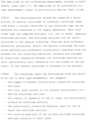
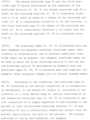
図1には、電気外科システム15の一実施形態の基本図が示されている。電気外科システム15は、供給接続部17および中性点接続部18を備える供給装置16を有する。供給接続部17は、器具19を供給装置16に電気的に接続するように機能する。電気的接続は、単極または多極接続とすることができる。接続は、単芯または多芯ケーブル20によって確立することができる。 A basic diagram of one embodiment of an
器具19は、患者の生体組織21の電気外科的治療のために構成される。組織21は、ヒトまたは動物の体の生体組織である。組織21の治療のために、器具19は、少なくとも1つまたは正確には1つの作用電極22を備える。組織21の治療のために、作用電極22と組織21との間に導電性接続を確立することができる。
図1に示す電気外科システム15では、器具19は、単極器具である。供給装置16から器具19の作用電極22、そして供給装置16に戻る電流回路は、器具19によって確立されるだけではなく、これに加えて、患者に導電的に取り付けられた別個の電極によって確立される。この追加の電極は、中性電極23として示すことができる。中性電極23は、この例によれば、多芯ケーブル24によって、供給装置16の中性点接続部18と電気的に接続されている。ケーブル24は、記載された実施形態では第1の導体25および第2の導体26として示される2つのコアまたは導体を有する(図2および図4から図6)。 In the
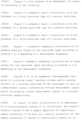
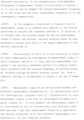
図2には、図1による電気外科システム15のブロック図が示されている。この実施形態では、供給装置16は、外部エネルギー供給源、例えばエネルギー供給グリッドのグリッド電圧源31に接続されたインバータ回路30を備える。グリッド電圧源31は、グリッド電圧を供給装置16に提供し、この例によればインバータ回路30に提供する。インバータ回路30は、供給接続部17に対して、または供給接続部において作用信号ASを提供または印加するように構成される。供給装置16によって供給接続部17に提供される作用信号ASは、印加された作用電圧UAまたは印加された作用電流IAとすることができ、作用電圧UAは作用電流IAを生成することができ、または作用電流IAは供給接続部17において作用電圧UAを生成することができる。作用信号ASは高周波信号であり、すなわち、作用電圧UAは高周波電圧であり、および/または作用電流IAは高周波電流である。作用信号ASは、組織21の治療中に作用電極22に供給される。治療中、作用電流IAは、作用電極22を介して組織21内に流れ、中性電極23に流れ、そこから中性点接続部18に戻る。この作用電流回路の全インピーダンスは、作用インピーダンス32として示すことができる。 In FIG. 2 a block diagram of the
図示の実施形態では、作用信号ASは、ケーブル20の信号線を介して器具19によって供給接続部17において要求される。1つまたは複数の治療期間Pの間、供給接続部17における作用信号ASは、その後、器具の作用電極22に印加される(図9~図11)。 In the illustrated embodiment, the activation signal AS is requested at the
オプションとして、作用信号ASは、供給接続部17において器具19に対して連続的に提供することもできる。この場合、器具19は、作用信号ASに基づいて治療期間P中に作用電極22に適切な電圧および/または適切な電流を提供するために、スイッチングデバイスを有することができる。スイッチングデバイスは、必要に応じて作用信号ASを変換または修正するために、インバータ回路または別の修正回路を任意選択的に備えることができる。 Optionally, the actuation signal AS can also be provided continuously to the
作用電極22に適切な電力を供給するためのこれらの記載された実施形態の組み合わせも可能である。 Combinations of these described embodiments for providing adequate power to the working
作用電圧UAは、作用電位と、基準電位例えばグランドGNDとの間の電位差に対応する。 The working voltage UA corresponds to the potential difference between the working potential and a reference potential, for example ground GND.
この実施形態では、供給装置16は、加えて、測定ユニット33を備える。測定ユニット33は、中性点接続部18において交流測定信号Mを提供または印加するように構成される。測定信号Mは、交流測定電圧UMまたは交流測定電流IMとすることができる。交流測定信号Mの波形および/または測定信号Mの振幅は、変化し得る。例えば、測定信号Mは、正弦波状もしくは共正弦波状、三角形状または方形波状であることができる。測定周波数fは、好ましくは少なくとも100Hzおよび最大1MHzの大きさを有する。 In this embodiment, the
交流測定電圧UMまたは交流測定電流IMのどちらが印加されるかに応じて、測定信号Mは、電極電流回路を通る交流測定電流IMまたは電極電流回路における交流測定電圧UMを生成する。電極電流回路は、第1の導体25から中性電極23、患者の組織21を経由して、再度中性電極23および第2の導体26を経由して戻る。電極電流回路における中性電極インピーダンスZNは、インピーダンス絶対値ZNabsおよび位相値φによって特徴付けられる。中性電極インピーダンスZNには、以下が適用される。Depending on whether an alternating measuring voltage UM or an alternating measuring current IM is applied, the measuring signal M produces an alternating measuring current IM through the electrode current circuit or an alternating measuring voltage UM in the electrode current circuit. The electrode current circuit runs from the


したがって、Re(ZN)は、中性電極インピーダンスZNの実数部であり、Im(ZN)は、中性電極インピーダンスZNの虚数部である。虚数部Im(ZN)および実数部Re(Zn)は、交流測定信号Mの測定周波数fに依存し得る。 Therefore, Re(ZN) is the real part of the neutral electrode impedance ZN, and Im(ZN) is the imaginary part of the neutral electrode impedance ZN. The imaginary part Im(ZN) and the real part Re(Zn) may depend on the measurement frequency f of the AC measurement signal M.
測定ユニット33は、2つ以上の測定周波数fそれぞれに対する交流測定電圧UMおよび交流測定電流IMに基づいて、インピーダンス絶対値ZNabsおよび/または位相値φを決定するように構成される。交流測定電圧UMと交流測定電流IMとの間の位相シフトは、この例による電極電流回路内の静電容量効果に、特に、中性電極23と患者の組織21との間の静電容量効果に起因する。これらの静電容量効果は、中性電極インピーダンスZNによって特徴付けられる。中性電極インピーダンスZNはまた、オーム抵抗を表し、オプションとして、電極電流回路内の誘起効果も表す。インピーダンス絶対値ZNabsは、見かけのインピーダンスとして表すことができる。The measuring
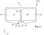
電気外科システム15には、異なる電極タイプの中性電極23が設けられている。一例にすぎないが、ここでは3つの異なる電極タイプ、すなわち第1の電極タイプT1(図4)、第2の電極タイプT2(図5)ならびに第3の電極タイプT3(図6)が示されている。
二次元中性電極23は、変形していない初期状態で、長手方向Lおよび横方向Qにまたがる平面に実質的に平行に延びる。中性電極23の幾何学的特性の説明は、この初期状態を参照する。 The two-dimensional
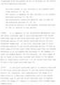
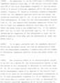
この実施形態では、電極タイプT1、T2、T3の各々は、少なくとも2つの導電性電極セクション、すなわち導電性の第1の電極セクション37と、導電性の第2の電極セクション38とを有する。中性電極23の接続領域39において、第1の電極セクション37は、第1の導体25と電気的に接続され、第2の電極セクション38は、第2の導体26と電気的に接続されている。接続領域39において、第1の電極セクション37および第2の電極セクション38はそれぞれ、割り当てられた導体25または26が接続されるストリップ導体状の延長部またはストリップ導体状の拡張部を有する。この延長部は、本明細書に示す実施形態では、中性電極23の長手方向Lに延びる。 In this embodiment, each of the electrode types T1, T2, T3 has at least two conductive electrode sections, a first
各電極タイプT1、T2、T3の第1の電極セクション37および第2の電極セクション38は、この実施形態では同一の寸法であり、したがって、等しい面積含有量および同じ幾何学的形状を有する。基準面Bに対して、第1の電極セクション37および第2の電極セクション38は、対称的に配置され、その間に位置するウェブ40によって互いに電気的および空間的に分離されている。基準面Bは、長手方向Lと平行に延び、横方向Qと直交して配向される。 The
第1の電極タイプT1は、第1の電極セクション37および第2の電極セクション38に加えて、導電性の第3の電極セクション41が存在する点で、第2の電極タイプT2および電極タイプT3と区別される。第1の電極タイプT1の中性電極23は、この例によれば正確に3つの電極セクション37、38、41を有するのに対して、第2の電極タイプT2および第3の電極タイプT3の中性電極23は、2つの電極セクション37、38のみを有する。 The first electrode type T1 differs from the second electrode type T2 and electrode type T3 in that, in addition to the
第1の電極タイプT1の中性電極23の第3の電極セクション41は、他の電極セクション37、38とは異なって、供給装置16に電気的に接続されておらず、または接続可能でもない。したがって、その電位は、供給装置16によって直接設定することができない。 The
中性電極23の全ての電極タイプT1、T2、T3の電極セクション37、38、41の全ては、中性電極23内で互いに直接電気的に接続されず、エラーのない通常動作で発生する電圧および電流に関して互いに電気的に絶縁されている。電気的接続は、患者の組織21を介して手術位置で間接的に確立される。中性電極23は、手術位置にある患者の組織21に取り付けられる側に導電性電極セクション37、38、41が設けられている。組織21から外方に面する反対側の裏面は、好ましくは、接触に対する保護が治療関係者に提供されるように電気的に絶縁される。例えば、電極セクション37、38、41は、中性電極23の基板材料上に適用することができ、基板材料またはカバー層によって裏面を覆われ、それによって電気的に絶縁され得る。 All of the
図4に概略的に示されるように、第3の電極セクション41は、他の電極セクション37、38の形状と著しく区別される。この例によれば、第3の電極セクションは、第1の電極セクション37および第2の電極セクション38の周りに延びており、特に接続領域39においてのみ開口している。第3の電極セクション41の2つの端部は、横方向Qにおいて互いに間隔を空けて配置されている。これら2つの端部間で、第3の電極セクション41は、第1の電極セクション37および第2の電極セクション38の周りに途切れることなく延びている。第3の電極セクション41の2つの端部間におけるその延長方向の長さは、この延長方向に直交する幅よりも少なくとも約10倍または20倍大きい。これにより、第3の電極セクション41は、ライン状の形状を有する。 As shown schematically in FIG. 4, the
したがって、導電性電極セクション37、38、41の数は、異なる電極タイプT1、T2、T3を区別するための識別基準である。追加的または代替的に、電極タイプT1、T2、T3は、以下の顕著な特徴の1つまたは複数によって互いに区別することができる。 The number of
-1つ、複数、または全ての存在する電極セクション37、38、41の面積含有量、
-1つ、複数、または全ての存在する電極セクション37、38、41の輪郭または幾何学的形状、
-電極セクション37、38、41に使用される導電性材料、
-存在する電極セクション37、38、41の互いに対する相対位置。- the areal content of one, several or all
- the contour or geometry of one, several or all
- electrically conductive material used for the
- the relative position of the
図示の実施形態では、第1の電極タイプT1はまた、第1の電極セクション37および第2の電極セクション38が異なる幾何学的形状を有するという点で第2の電極タイプT2および第3の電極タイプT3と区別することが明らかである。第1の電極タイプT1では、第1の電極セクション37および第2の電極セクション38は、互いから外方に面する外側に、弧状に、この例によれば、典型的な円弧形状に延びる外縁部42を有する。これに対して、第2の電極タイプT2および第3の電極タイプT3では、外縁部42は、少なくとも部分的に直線状であり、この実施形態では、長手方向Lに延びる。 In the illustrated embodiment, the first electrode type T1 also overlaps the second electrode type T2 and the third electrode in that the
したがって、中性電極23の第1の電極タイプT1では、第1の電極セクション37および第2の電極セクション38はそれぞれ、半円または半楕円の形状を実質的に有し、第2の電極タイプT2および第3の電極タイプT3では、それぞれ、丸みを帯びた縁部を有する正方形または丸みを帯びた縁部を有する長方形の形状を実質的に有する。 Thus, in the first electrode type T1 of the
第2の電極タイプT2および第3の電極タイプT3は、主に電極セクション37、38の寸法によって区別される。第2の電極タイプT2では、電極セクション37、38の横方向Qの幅は、少なくとも電極セクション37、38の長手方向Lの長さと同じ大きさである。これに対して、第3の電極タイプT3では、電極セクション37、38の長手方向Lの長さは、電極セクション37、38の横方向Qの幅よりも大きい。 The second electrode type T2 and the third electrode type T3 are mainly distinguished by the dimensions of the
ここに示す電極タイプT1、T2、T3は、可能な異なる電極タイプの例にすぎない。追加的または代替的に、1つまたは複数の追加の電極タイプが存在することができる。例えば、第1の電極セクション37および第2の電極セクション38がここに示される電極タイプT1、T2、T3と幾何学的形状によって区別され、例えば、丸みを帯びた縁部を有するまたは有さない他の多角形形状を含む電極タイプを使用することができる。 The electrode types T1, T2, T3 shown here are only examples of different possible electrode types. Additionally or alternatively, one or more additional electrode types may be present. For example, the
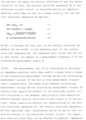
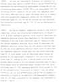
本発明によれば、中性点接続部18に接続された電極タイプT1、T2、T3は、自動的に決定される。方法50(図3)では、本発明によれば、第1の方法ステップ51において、それぞれの電極タイプT1、T2、T3の中性電極23は、供給装置16の中性点接続部18に接続され、設けられた電極セクション37、38、および任意選択的に41が患者(特に患者の皮膚)と導電接触するように患者に取り付けられる。中性電極23は、例えば、自己接着性とすることができる。 According to the invention, the electrode types T1, T2, T3 connected to the
第2の方法ステップ52では、続いて、少なくとも1つのインピーダンス絶対値ZNabsおよび少なくとも1つの位相値φが、決定される。例えば、1つの第1の測定周波数f1に対して1つのインピーダンス絶対値ZNabsを決定し、1つの第2の測定周波数f2に対して1つの位相値φを決定することで十分であることができ、第2の測定周波数f2は、第1の測定周波数f1よりも低い。第1の測定周波数f1および第2の測定周波数f2は、好ましくは、100Hz~1.0MHzの周波数範囲から選択される。第1の測定周波数f1は、最小5.0kHz、例えば14kHz~15kHzの大きさを有することができる。この例によれば、第2の測定周波数f2は、最大5.0kHz、好ましくは最大1.0kHzの大きさを有する。この実施形態では、第2の測定周波数f2は、周波数範囲の下限の近くで選択され、例えば100Hzに等しくすることができ、または100Hz~200Hzの範囲内にすることができる。In a
第3の方法ステップ53では、少なくとも1つのインピーダンス絶対値ZNabsおよび少なくとも1つの位相値φに基づいて、接続された中性電極23の電極タイプT1、T2、T3を決定することができる。In a
接続された中性電極23の電極タイプT1、T2、T3の認識により、供給装置16は、電極タイプT1、T2、T3に適合された少なくとも1つの動作モードを事前設定することができる。動作モードまたは可能な動作モードの1つは、自動的に設定することができ、またはユーザによって手動で選択することができる。例えば、決定された電極タイプT1、T2、T3に応じて、中性電極23を流れる電力および/または電流の制限値を使用することができる。したがって、組織21内の電流密度は、電極タイプT1、T2、T3のサイズおよび/または幾何学的形状に適合するように制限することができる。 Through recognition of the electrode type T1, T2, T3 of the connected
それぞれ1つの割り当てられた測定周波数f1、f2における少なくとも1つのインピーダンス絶対値ZNabsおよび少なくとも1つの位相値φの決定で、十分である。第1の測定周波数f1および第2の測定周波数f2において、1つのインピーダンス絶対値ZNabsおよび/または1つの位相値φが、それぞれ決定される。ここに示す実施形態の改変例では、3つ以上の測定周波数f1、f2を、少なくとも1つのインピーダンス絶対値ZNabsおよび少なくとも1つの位相値φの決定に使用することもできる。決定されるインピーダンス絶対値ZNabsの数および決定される位相値φの数は、等しいかまたは異なる量であることができる。2つ以上のインピーダンス絶対値ZNabsおよび/または2つ以上の位相値φが決定される場合、2つ以上のインピーダンス絶対値は、異なる測定周波数fにおいて決定され、および/または2つ以上の位相値φは、異なる測定周波数f1、f2において決定される。It is sufficient to determine at least one impedance absolute value ZNabs and at least one phase value φ at each one assigned measurement frequency f1, f2. One absolute impedance value ZNabs and/or one phase value φ is determined at the first measurement frequency f1 and the second measurement frequency f2, respectively. In a modification of the embodiment shown here, three or more measurement frequencies f1, f2 can also be used for determining at least one absolute impedance value ZNabs and at least one phase value φ. The number of absolute impedance values ZNabs determined and the number of phase values φ determined can be equal or different quantities. If two or more absolute impedance values ZNabs and/or two or more phase values φ are determined, the two or more absolute impedance values are determined at different measurement frequencies f and/or two or more phase values The value φ is determined at different measurement frequencies f1, f2.
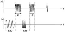
少なくとも1つのインピーダンス絶対値および少なくとも1つの位相値を決定するために、測定信号Mが、電極電流回路、したがって中性電極23に印加される。説明したように、交流測定信号Mは、印加された交流測定電圧UMまたは印加された交流測定電流IMとすることができる。測定信号Mは、この例によれば、第1の測定周波数f1および第2の測定周波数f2の2つの異なる測定周波数fにおいて少なくとも中性電極23に印加される(図9~図11)。これにより、設定される測定周波数f1、f2の順番を任意に選択することができる。図9~図11に示す測定信号Mの概略的な時間依存の進行では、例としてのみ、第2の測定周波数f2が最初に設定され、第1の測定周波数f1がその後にそれぞれ設定される。 A measurement signal M is applied to the electrode current circuit and thus to the
図9および図10に示す例では、測定信号Mは、治療期間Pの外側で中性電極23にそれぞれ印加される。そうすることで、作用信号ASはまた、中性電極23を介して供給装置16への電流逆流を生成するので、作用信号ASと測定信号Mとが互いに影響を及ぼすことが回避される。 In the example shown in FIGS. 9 and 10, the measurement signal M is applied to the
これに代えて、測定信号Mと治療期間Pとを少なくとも一時的に重複させることも可能である。この場合、治療期間P中に設定される測定周波数fは、作用信号ASの作用周波数(作用電圧UAおよび/または作用電流IA)とは明らかに異なるように選択される。そのような時間的重なりは、例として図11に示されている。 Alternatively, it is also possible for the measurement signal M and the treatment period P to overlap at least temporarily. In this case, the measurement frequency f set during the treatment period P is selected to be clearly different from the action frequency of the action signal AS (action voltage UA and/or action current IA). Such a temporal overlap is shown in FIG. 11 as an example.
測定信号Mは、実質的に中断することなく、異なる測定周波数f1、f2間で切り替えることができる(図9および図11)。これの代わりに、測定信号Mを休止によって中断することもできる(図10)。この例では、測定信号Mは、1つまたは代替的に複数の治療期間Pによって中断され、したがって、測定信号Mは、時間的距離を置いて異なる測定周波数f1、f2において中性電極23に印加される。 The measurement signal M can be switched between different measurement frequencies f1, f2 substantially without interruption (FIGS. 9 and 11). As an alternative to this, the measurement signal M can also be interrupted by a pause (FIG. 10). In this example, the measurement signal M is interrupted by one or alternatively several treatment periods P, so that the measurement signal M is applied to the
各設定測定周波数において、インピーダンス絶対値ZNabsおよび/または位相値φは、測定ユニット33において交流測定電圧UMおよび交流測定電流IMの評価によって決定することができる。その後、少なくとも1つのインピーダンス絶対値ZNabsおよび少なくとも1つの位相値φに基づいて、異なる電極タイプT1、T2、T3の所定の比較値との比較を実施することができ、そこから、接続された電極タイプT1、T2、T3を決定または識別することができる。At each set measuring frequency, the impedance absolute value ZNabs and/or the phase value φ can be determined in the measuring
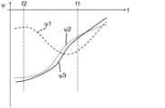
例として、比較曲線の形態の比較値が、図7~図8に概略的に示されている。第1のインピーダンス絶対値曲線Z1は、第1の電極タイプT1についての測定周波数fに依存するインピーダンス絶対値ZNabsを記述する。これと同様に、第2のインピーダンス絶対値曲線Z2は、第2の電極タイプT2のインピーダンス絶対値ZNabsを記述し、第3のインピーダンス絶対値曲線Z3は、第3の電極タイプT3のインピーダンス絶対値ZNabsを記述する。第1の位相曲線φ1は、第1の電極タイプT1についての測定周波数fに依存する位相値を記述する。これと同様に、第2の位相曲線φ2は、第2の電極タイプT2についての位相値φを記述し、第3の位相曲線φ3は、第3の電極タイプT3についての位相値φを記述する。インピーダンス絶対値曲線Z1、Z2、Z3は、図7に概略的に示されており、位相曲線φ1、φ2、φ3は、概略的に、一例として図8に示されている。加えて、この例によって使用される測定周波数f1、f2が、図7および図8に示されている。By way of example, comparative values in the form of comparative curves are shown schematically in FIGS. 7-8. The first impedance absolute value curve Z1 describes the impedance absolute value ZNabs as a function of the measurement frequency f for the first electrode type T1. Similarly, the second impedance absolute value curve Z2 describes the impedance absolute value ZNabs of the second electrode type T2, and the third impedance absolute value curve Z3 describes the impedance absolute value ZN abs of the third electrode type T3. Describe the value ZNabs . The first phase curve φ1 describes the phase value depending on the measurement frequency f for the first electrode type T1. Similarly, the second phase curve φ2 describes the phase value φ for the second electrode type T2, and the third phase curve φ3 describes the phase value φ for the third electrode type T3. . The impedance absolute value curves Z1, Z2, Z3 are shown schematically in FIG. 7, and the phase curves φ1, φ2, φ3 are shown schematically in FIG. 8 by way of example. Additionally, the measurement frequencies f1, f2 used by this example are shown in FIGS. 7 and 8.
説明したように、第1の測定周波数f1における中性電極インピーダンスZNのインピーダンス絶対値ZNabsおよび第2の測定周波数f2における中性電極インピーダンスZNの位相値φを決定するだけで十分であることができる。インピーダンス絶対値および位相の異なる周波数依存値に基づいて、接続された電極タイプT1、T2、T3をその後そこから認識することができる。少なくとも使用される測定周波数f1、f2について、少なくとも1つのインピーダンス絶対値ZNabsおよび少なくとも1つの位相値φに対するそれぞれ割り当てられた比較値は、例えば測定ユニット33において事前定義され、それにより、電極タイプT1、T2、T3は、決定された少なくとも1つのインピーダンス絶対値ZNabsおよび決定された少なくとも1つの位相値φの比較によって認識可能である。As explained, it is sufficient to determine the impedance absolute value ZNabs of the neutral electrode impedance ZN at the first measurement frequency f1 and the phase value φ of the neutral electrode impedance ZN at the second measurement frequency f2. can. Based on the different frequency-dependent values of the impedance absolute value and the phase, the connected electrode types T1, T2, T3 can then be recognized therefrom. For at least the used measurement frequencies f1, f2, the respective assigned comparison values for at least one impedance absolute value ZNabs and at least one phase value φ are predefined, for example in the
ここでも、インピーダンス絶対値および位相値は、それぞれ2つ以上の測定周波数fにおいて決定することもでき、決定されるインピーダンス絶対値および位相値の数は変化し得ることが示されている。 Here again, it is shown that the impedance magnitude and phase values can each be determined at more than one measurement frequency f, and the number of impedance magnitude and phase values determined can vary.
本発明は、電気外科システム15および方法50に関する。電気外科システム15および方法50は、使用される中性電極23の電極タイプT1、T2、T3を決定するように構成される。このために、交流測定信号Mが、少なくとも2つの異なる測定周波数f1、f2において中性電極23に印加される。各測定周波数f1、f2において、インピーダンス絶対値ZNabsまたは位相値φまたはその両方が、中性電極23の中性電極インピーダンスZNについて決定される。少なくとも1つのインピーダンス絶対値ZNabsおよび少なくとも1つの位相値φが、決定される。少なくとも1つのインピーダンス絶対値ZNabsおよび少なくとも1つの位相値φに基づいて、接続された中性電極23の電極タイプT1、T2、T3は、特に少なくとも1つのインピーダンス絶対値ZNabsおよび少なくとも1つの位相値φについての既知の比較値との比較によって決定される。The present invention relates to an
15 電気外科システム
16 供給装置
17 供給接続部
18 中性点接続部
19 器具
20 器具用ケーブル
21 組織
22 作用電極
23 中性電極
24 中性電極用ケーブル
25 第1の導体
26 第2の導体
30 インバータ回路
31 グリッド電圧源
32 作用インピーダンス
33 測定ユニット
37 第1の電極セクション
38 第2の電極セクション
39 接続領域
40 ウェブ
41 第3の電極セクション
42 外縁部
50 方法
51 第1の方法ステップ
52 第2の方法ステップ
53 第3の方法ステップ
φ 位相値
φ1 第1の位相曲線
φ2 第2の位相曲線
φ3 第3の位相曲線
AS 作用信号
B 基準面
f 測定周波数
f1 第1の測定周波数
f2 第2の測定周波数
GND グランド
IA 作用電流
IM 交流測定電流
L 長手方向
M 測定信号
P 治療期間
Q 横方向
t 時間
T1 第1の電極タイプ
T2 第2の電極タイプ
T3 第3の電極タイプ
UA 作用電圧
UM 交流測定電圧
Z1 第1のインピーダンス絶対値曲線
Z2 第2のインピーダンス絶対値曲線
Z3 第3のインピーダンス絶対値曲線
ZN 中性電極インピーダンス
ZNabs インピーダンス絶対値15
19
Claims (15)
Translated fromJapanese前記供給装置(16)が、少なくとも2つの異なる測定周波数(f1、f2)において交流測定信号(M)を前記中性点接続部(18)に印加し、前記測定周波数(f1、f2)の少なくとも1つについて前記中性電極(23)の中性電極インピーダンス(ZN)の少なくとも1つのインピーダンス絶対値(ZNabs)を決定し、前記測定周波数(f1、f2)の少なくとも1つについて前記中性電極インピーダンス(ZN)の少なくとも1つの位相値(φ)を決定し、前記少なくとも1つのインピーダンス絶対値(ZNabs)および前記少なくとも1つの位相値(φ)に基づいて、前記接続された中性電極(23)の電極タイプ(T1、T2、T3)を決定するように構成される、電気外科システム。An electrosurgical system (15) comprising a delivery device (16) having a neutral connection (18) and a neutral electrode (23) connected to said neutral connection (18); the neutral electrode (23) is configured to be electrically conductively connected to a patient;
Said supply device (16) applies an alternating measuring signal (M) to said neutral connection (18) at at least two different measuring frequencies (f1, f2), at least one of said measuring frequencies (f1, f2). determining at least one impedance absolute value (ZNabs ) of the neutral electrode impedance (ZN) of said neutral electrode (23) for one of said neutral electrodes (23); determining at least one phase value (φ) of an impedance (ZN), and determining at least one phase value (φ) of the connected neutral electrode( 23) an electrosurgical system configured to determine an electrode type (T1, T2, T3);
前記中性電極(23)と患者との間に導電性接続が存在するように前記中性電極(23)を前記患者に取り付けるステップと、
交流測定信号(M)を少なくとも2つの異なる測定周波数(f1、f2)において前記中性電極(23)にそれぞれ印加するステップと、
前記測定周波数(f1、f2)の少なくとも1つについて前記中性電極(23)の中性電極インピーダンス(ZN)の少なくとも1つのインピーダンス絶対値(ZNabs)を決定するステップと、
前記測定周波数(f1、f2)の少なくとも1つについて前記中性電極(23)の前記中性電極インピーダンス(ZN)の少なくとも1つの位相値(φ)を決定するステップと、
前記少なくとも1つのインピーダンス絶対値(ZNabs)および前記少なくとも1つの位相値(φ)に基づいて、接続された前記中性電極(23)の電極タイプ(T1、T2、T3)を決定するステップとを含む方法。A method for determining the electrode type (T1, T2, T3) of a neutral electrode (23), comprising:
attaching the neutral electrode (23) to the patient such that there is a conductive connection between the neutral electrode (23) and the patient;
applying an alternating current measurement signal (M) to said neutral electrode (23) at at least two different measurement frequencies (f1, f2), respectively;
determining at least one impedance absolute value (ZNabs ) of a neutral electrode impedance (ZN) of the neutral electrode (23) for at least one of the measurement frequencies (f1, f2);
determining at least one phase value (φ) of the neutral electrode impedance (ZN) of the neutral electrode (23) for at least one of the measurement frequencies (f1, f2);
determining an electrode type (T1, T2, T3) of the connected neutral electrode (23) based on the at least one absolute impedance value (ZNabs ) and the at least one phase value (φ); method including.
Applications Claiming Priority (2)
| Application Number | Priority Date | Filing Date | Title |
|---|---|---|---|
| EP22169248 | 2022-04-21 | ||
| EP22169248.6AEP4265211A1 (en) | 2022-04-21 | 2022-04-21 | Electrical surgery system and method for determining an electrode type of a neutral electrode |
Publications (1)
| Publication Number | Publication Date |
|---|---|
| JP2023160756Atrue JP2023160756A (en) | 2023-11-02 |
Family
ID=81346274
Family Applications (1)
| Application Number | Title | Priority Date | Filing Date |
|---|---|---|---|
| JP2023063845APendingJP2023160756A (en) | 2022-04-21 | 2023-04-11 | Electrosurgical system and method for determining electrode type of neutral electrode |
Country Status (6)
| Country | Link |
|---|---|
| US (1) | US20230338078A1 (en) |
| EP (1) | EP4265211A1 (en) |
| JP (1) | JP2023160756A (en) |
| KR (1) | KR20230150198A (en) |
| CN (1) | CN116919571A (en) |
| BR (1) | BR102023006283A2 (en) |
Family Cites Families (12)
| Publication number | Priority date | Publication date | Assignee | Title |
|---|---|---|---|---|
| US5630426A (en) | 1995-03-03 | 1997-05-20 | Neovision Corporation | Apparatus and method for characterization and treatment of tumors |
| US6007532A (en)* | 1997-08-29 | 1999-12-28 | 3M Innovative Properties Company | Method and apparatus for detecting loss of contact of biomedical electrodes with patient skin |
| EP1289415A4 (en) | 2000-05-18 | 2008-12-03 | Nuvasive Inc | Tissue discrimination and applications in medical procedures |
| US6813515B2 (en) | 2002-01-04 | 2004-11-02 | Dune Medical Devices Ltd. | Method and system for examining tissue according to the dielectric properties thereof |
| US8187263B2 (en)* | 2008-02-04 | 2012-05-29 | Tyco Healthcare Group Lp | System and method for return electrode monitoring |
| US20090234352A1 (en)* | 2008-03-17 | 2009-09-17 | Tyco Healthcare Group Lp | Variable Capacitive Electrode Pad |
| DE102009013917A1 (en)* | 2008-10-30 | 2010-05-12 | Erbe Elektromedizin Gmbh | Electrosurgical device with a temperature measuring device, method for determining a temperature and / or a temperature change at a neutral electrode |
| US8628524B2 (en)* | 2009-04-27 | 2014-01-14 | Bovie Medical Corporation | Return electrode detection and monitoring system and method thereof |
| EP2537479B1 (en) | 2011-06-20 | 2014-04-16 | Erbe Elektromedizin GmbH | Controlling a medical device depending on neutral electrode impedance |
| DE102016214704A1 (en) | 2016-08-08 | 2018-02-08 | Olympus Winter & Ibe Gmbh | Electrosurgical system with measuring unit |
| US11510720B2 (en)* | 2018-09-07 | 2022-11-29 | Cilag Gmbh International | Managing simultaneous monopolar outputs using duty cycle and synchronization |
| DE102019209333A1 (en) | 2019-06-27 | 2020-12-31 | B. Braun Melsungen Aktiengesellschaft | Method for determining a local tissue type of body tissue and medical system for carrying out such a method |
- 2022
- 2022-04-21EPEP22169248.6Apatent/EP4265211A1/enactivePending
- 2023
- 2023-04-04BRBR102023006283-0Apatent/BR102023006283A2/enunknown
- 2023-04-11JPJP2023063845Apatent/JP2023160756A/enactivePending
- 2023-04-12KRKR1020230047911Apatent/KR20230150198A/enactivePending
- 2023-04-19USUS18/136,754patent/US20230338078A1/enactivePending
- 2023-04-20CNCN202310426881.2Apatent/CN116919571A/enactivePending
Also Published As
| Publication number | Publication date |
|---|---|
| KR20230150198A (en) | 2023-10-30 |
| US20230338078A1 (en) | 2023-10-26 |
| EP4265211A1 (en) | 2023-10-25 |
| BR102023006283A2 (en) | 2023-10-31 |
| CN116919571A (en) | 2023-10-24 |
Similar Documents
| Publication | Publication Date | Title |
|---|---|---|
| US10653471B2 (en) | Systems and methods for arc detection and drag adjustment | |
| AU2008202047B9 (en) | Adjustable impedance electrosurgical electrodes | |
| US10314642B2 (en) | Electrocautery method and apparatus | |
| US8235980B2 (en) | Electrosurgical system for measuring contact quality of a return pad | |
| US10022090B2 (en) | Nerve protecting dissection device | |
| CN100409821C (en) | Method and measuring device for determining the transition impedance between two parts of a subdivided neutral electrode | |
| JP5307125B2 (en) | HF surgical inspection device | |
| US12390270B2 (en) | Fibroid ablation positioning device and methods | |
| AU2008275543B2 (en) | Electrocautery method and apparatus | |
| US20060111711A1 (en) | Surgical instrument | |
| JP2009082707A (en) | Real-time arc control in electrosurgical generator | |
| JP2023160756A (en) | Electrosurgical system and method for determining electrode type of neutral electrode | |
| KR101638247B1 (en) | Instrument test arrangement | |
| JP2023138392A (en) | Electrosurgical system and method for checking electrical connection between neutral electrode and patient | |
| US11207122B2 (en) | System, apparatus, and method for powering a bipolar energy controller | |
| CN113766889B (en) | Crack detection in bipolar electrosurgical instrument sheaths | |
| EP2853286A1 (en) | Device for treatment of perimplantitis | |
| US20240138897A1 (en) | Electrosurgical system and method for operation thereof | |
| CN116472001A (en) | Electronic device for biomedical use implementing QMR technology | |
| WO2019058222A1 (en) | Electrode disconnect detection |