JP2023158856A - gear puller - Google Patents
gear pullerDownload PDFInfo
- Publication number
- JP2023158856A JP2023158856AJP2022068882AJP2022068882AJP2023158856AJP 2023158856 AJP2023158856 AJP 2023158856AJP 2022068882 AJP2022068882 AJP 2022068882AJP 2022068882 AJP2022068882 AJP 2022068882AJP 2023158856 AJP2023158856 AJP 2023158856A
- Authority
- JP
- Japan
- Prior art keywords
- center
- wire
- claw
- center plate
- arm
- Prior art date
- Legal status (The legal status is an assumption and is not a legal conclusion. Google has not performed a legal analysis and makes no representation as to the accuracy of the status listed.)
- Pending
Links
- 210000000078clawAnatomy0.000claimsabstractdescription89
- 238000010586diagramMethods0.000abstract1
- 238000003780insertionMethods0.000description7
- 230000037431insertionEffects0.000description7
- 238000000605extractionMethods0.000description3
- 230000001788irregularEffects0.000description2
- 230000002093peripheral effectEffects0.000description2
- 229910000831SteelInorganic materials0.000description1
- 238000009434installationMethods0.000description1
- 238000012423maintenanceMethods0.000description1
- 230000004048modificationEffects0.000description1
- 238000012986modificationMethods0.000description1
- 230000000717retained effectEffects0.000description1
- 238000005070samplingMethods0.000description1
- 229910001220stainless steelInorganic materials0.000description1
- 239000010959steelSubstances0.000description1
Images


Landscapes
- Hand Tools For Fitting Together And Separating, Or Other Hand Tools (AREA)
Abstract
Translated fromJapanese
Description
Translated fromJapanese本発明は、軽量で、一人でシャフトからギヤやプーリ等の引抜対象物を効率よく引き抜くことができるギアプーラの改良に関する。 The present invention relates to an improvement in a gear puller that is lightweight and allows one person to efficiently pull out objects such as gears and pulleys from a shaft.
各種機械のシャフトにはさまざまな大きさのギアやプーリー等の引抜対象物が取り付けられている。この引抜対象物を交換する必要がある場合には、シャフトから引抜対象物を引き抜くためにギアプーラが使用される。シャフトに対してこれら引抜対象物の取付孔は高い嵌合精度で嵌合されており、引抜対象物をシャフトに対して正確に平行に引き抜くことが要求されている。
また、これら引抜対象物には直径の大きいものから小さいもの、厚みの大きいものから薄いものなどを様々な種類のものがあり、その重量は概して大きい。Objects to be extracted, such as gears and pulleys of various sizes, are attached to the shafts of various machines. If the object needs to be replaced, a gear puller is used to pull the object from the shaft. The attachment holes of these objects to be pulled out are fitted to the shaft with high fitting precision, and it is required that the objects to be pulled out can be pulled out accurately parallel to the shaft.
Furthermore, these objects to be drawn come in various types, ranging from large to small diameters, thick to thin, etc., and their weights are generally large.
このようなギアプーラの一例として、外周面にネジが刻設されたセンターボルトと、このネジ部分に噛合う雌螺子部が設けられたセンタープレートと、先端に爪部を備えた一対の爪アームと、センタープレートと爪アームとを接続するリンクとから成るギアプーラがある(特許文献1)。
このギアプーラを使用する場合、ギヤに爪アームの先端内側に突出した爪部をギヤの外周の対称位置に引っ掛け、続いて、センターボルトの先端部をシャフトの先端部に押し当て、センタープレートの両肩部分に設けられているリンクが張る処までセンターボルトを回転させギアプーラをセットする。An example of such a gear puller is a center bolt with a thread carved on its outer circumferential surface, a center plate with a female thread that engages with the thread, and a pair of claw arms with claws at the tips. There is a gear puller including a link connecting a center plate and a claw arm (Patent Document 1).
When using this gear puller, hook the claw part protruding inside the tip of the claw arm onto the gear at a symmetrical position on the outer circumference of the gear, then press the tip of the center bolt against the tip of the shaft, and then Rotate the center bolt until the link provided on the shoulder part tightens and set the gear puller.
この状態でセンターボルトのヘッドにスパナ等を掛けてセンターボルトを回転させると、リンクを介してセンタープレートとこれに揺動状態で接続されている爪アームがギヤを外す方向に移動し、ギヤをシャフトから引き抜くことになる。
このギアプーラの左右の爪アームは上記のように、センタープレートの両肩にリンクを介して揺動可能に取り付けられていて取り扱いにくく、このギアプーラを使用する場合、両方の爪アームをしっかり固定しながら、センターボルトを回転させていく必要がある。
このセンターボルトを回転させることによってシャフトの先端部にセンターボルトの先端部を押し付けて行くが、ギヤ等を引き抜こうとする力が十分に作用するまでは、リンクによって支持されている爪アームが安定せず、一人で作業すると爪部がギヤから外れやすい。In this state, when the center bolt is rotated by applying a wrench or the like to the head of the center bolt, the center plate and the pawl arm, which is swingably connected to the center plate via the link, move in the direction of removing the gear. It will have to be pulled out of the shaft.
As mentioned above, the left and right claw arms of this gear puller are swingably attached to both shoulders of the center plate via links, making them difficult to handle.When using this gear puller, both claw arms must be firmly fixed. , it is necessary to rotate the center bolt.
By rotating this center bolt, the tip of the center bolt is pressed against the tip of the shaft, but the claw arm supported by the link is not stable until enough force is applied to pull out the gear etc. If you are working alone, the pawl part will easily come off the gear.
そのため、抜き取り作業時間を短縮するためには、一人が両方の爪アームを両手でしっかりと固定し、もう一人がセンタープレートを片手で保持し、残る他の手でセンターボルトを回転させるという作業が必要となっていた。即ち、このギアプーラでは一人での作業は困難であり、二人での作業が必要となり、メンテナンス時の抜き取り作業工数が増大していた。 Therefore, in order to reduce the extraction time, one person should firmly fix both claw arms with both hands, and the other person should hold the center plate with one hand while rotating the center bolt with the other hand. It had become necessary. That is, it is difficult for one person to work on this gear puller, and two people are required to work on it, which increases the number of man-hours required for extraction work during maintenance.
そこで、シャフトからギヤ等を取り外すときに、一人で効率よく操作できるギアプーラが提案された(特許文献2)。
このギアプーラは、センターボルトがセンタープレートの雌螺子部に螺合されており、このセンタープレートの雌螺子部には、左右対称に張出したガイドが設けられ、このガイドに左右一対の爪アームがスライド自在に設けられている。爪アームに、先端に爪部が形成された爪アーム本体と、ガイドをスライドする取付胴部とからなる。Therefore, a gear puller has been proposed that can be operated efficiently by one person when removing a gear or the like from a shaft (Patent Document 2).
In this gear puller, the center bolt is screwed into the female threaded part of the center plate, and the female threaded part of the center plate is provided with a guide that protrudes symmetrically, and a pair of left and right claw arms slide into this guide. It is set freely. The claw arm consists of a claw arm main body with a claw formed at the tip, and a mounting body that slides on a guide.
そして、センタープレートの上方に軸受部材が設けられており、この軸受部材にピニオンギアが取り付けられ、センタープレートに対してピニオンギアが回転自在に装着されている。
そして、ガイドに挿通された左右の取付胴部にラックが片持ちで取り付けられている。ラックの取付位置はピニオンに噛合するようにガイドの上方でガイドに平行に取り付けられる。
ラックはピニオンギアに前後から噛合するように左右の取付胴部に片持ちで設けられ、左右の爪アームがピニオンギアを介して連動開閉するようになっている。
このラックは、センタープレートの上方に設けられた軸受部材に合わせて左右の取付胴に設置されているために、軸受部材の分だけギアプーラの全長が大きくなる。A bearing member is provided above the center plate, a pinion gear is attached to the bearing member, and the pinion gear is rotatably mounted to the center plate.
A rack is attached in a cantilevered manner to the left and right mounting bodies that are inserted through the guides. The rack is mounted above and parallel to the guide so as to mesh with the pinion.
The rack is cantilevered on the left and right mounting bodies so as to mesh with the pinion gear from the front and rear, and the left and right claw arms open and close in conjunction with each other via the pinion gear.
Since this rack is installed on the left and right mounting barrels in line with the bearing members provided above the center plate, the total length of the gear puller increases by the bearing members.
使用時には、取付胴部をガイドに沿って移動させ、爪アームを連動開閉し、爪部をギヤに引っ掛け、この状態で爪アームをガイドに固定する。続いてセンターボルトの先端部をシャフトの先端部に押し当て、軸心を一致させた状態でセンターボルトを回転させる。これによって、センタープレートと共に爪部を軸方向に移動させ、シャフトからギヤ等を引き抜くことができる。
この作業は、一方の爪部を移動させると、他方の爪がピニオンギアを介して連動してセンターボルトを中心にして対象に開閉するので、一人の作業者でシャフトからギヤ等を引き抜くことができるとしている。When in use, the mounting body is moved along the guide, the claw arms are opened and closed in conjunction with each other, the claws are hooked on the gear, and in this state the claw arms are fixed to the guide. Next, press the tip of the center bolt against the tip of the shaft, and rotate the center bolt while aligning the axes. Thereby, the claw portion can be moved in the axial direction together with the center plate, and the gear etc. can be pulled out from the shaft.
In this work, when one claw is moved, the other claw opens and closes symmetrically around the center bolt in conjunction with the pinion gear, so a single worker can pull out the gear etc. from the shaft. He says it can be done.
しかしながら、先行技術文献2に記載のギアプーラには、先行技術文献1のギアプーラにはなかったピニオンギアや、ガイドと同じ長さでガイドの前後に設けられた前後一対のラック、ピニオンギアを回転保持する軸受機構などがそれぞれ装着されており、ギアプーラ全体の重量が先行技術文献1のギアプーラに比べて倍近く重くなり、高さも軸受機構分だけ大きくなっている。ギヤ等の引き抜き作業は、上記のように作業工数を短縮する上で一人で行うのが好ましいが、ギアプーラ全体の形状が大きく、且つ重量が重くなると一人でこの作業をこなすには支障を来す。 However, the gear puller described in Prior
本発明はかかる従来例の問題点を解決し、全体の形状や重量を増大させることなく、爪アームが片手でスムーズに開閉することが可能で、取り扱いが簡便なギアプーラを提供することを目的とする。 It is an object of the present invention to solve the problems of the prior art and provide a gear puller whose claw arm can be smoothly opened and closed with one hand without increasing the overall shape or weight, and which is easy to handle. do.
請求項1に記載した本発明に係るギアプーラAは以下のような構成である。
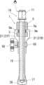
一端に回転操作ヘッド11が設けられ、回転操作ヘッド11に続く軸部分15の外周に雄螺子が刻設され、他端に引抜対象物Cが嵌合されたシャフトBの端面に当接するセンタ突起17が設けられたセンターボルト10と、
前記センターボルト10が螺進螺退可能に螺挿された雌螺子部5と、前記雌螺子部5から前記センターボルト10に対して左右に伸びたガイド部2とを含むセンタープレート1と、
前記ガイド部2にスライド可能に取り付けられ、且つ前記センターボルト10のセンタ突起17と同方向に伸び、シャフトBから抜き出される引抜対象物Cを係止する爪部28が、その先端に設けられた左右一対の爪アーム20と、
前記左右のガイド部2の先端部分を通り、前記センタープレート1の前面から背面に至るように配設されて前記センタープレート1の周囲を取り巻くように設けられた作動ワイヤ30とで構成され、
前記作動ワイヤ30は、一方の爪アーム20Lの、前記センタープレート1の前面側に設けられたワイヤ取付部24Lに固定され、且つ、他方の爪アーム20Rの、前記センタープレート1の背面側に設けられたワイヤ取付部24Rに固定されていることを特徴とする。The gear puller A according to the present invention described in
A
A
A
an actuating
The
請求項2は、請求項1に記載した本発明に係るギアプーラAにおいて、
前記左右のガイド部2の先端部分に作動ワイヤ30の移動を助ける移動補助部材40が設けられていることを特徴とする。
The present invention is characterized in that a
請求項3は、請求項2に記載した本発明に係るギアプーラAにおいて、
前記移動補助部材40は、作動ワイヤ30の移動方向に回転する回転コマ41、又は作動ワイヤ30の移動方向に沿って設けられ、前記作動ワイヤ30が滑動する円弧状ガイド溝45で構成されていることを特徴とする。
The movement
請求項4は、請求項3に記載した本発明に係るギアプーラAにおいて、
前記回転コマ41又は円弧状ガイド溝45の半径Rは、センタープレート1の前後幅方向の中心線CLから作動ワイヤ30のワイヤ取付部24までの前後幅Wより小さく形成されていることを特徴とする。
The radius R of the
請求項5は、請求項1又は2に記載した本発明に係るギアプーラAにおいて、
センタープレート1の雌螺子部5の前面から背面までの前後幅Sが、前記センタープレート1の前面及び背面を通過する作動ワイヤ30の前後幅2Wより大きく形成され、前記雌螺子部5の前面と背面に前記作動ワイヤ30が通過する逃げ溝5mが凹設されていることを特徴とする。
The front-to-back width S from the front to the back of the female threaded
請求項6は、請求項1又は2に記載した本発明に係るギアプーラAにおいて、
爪アーム20には、ガイド部2に爪アーム20をそれぞれ固定するロック部材50が設けられていことを特徴とする。
The
本発明のギアプーラAは、センターボルト10を中心に、爪アーム20の左右方向での等距離開閉移動が一本の作動ワイヤ30にて連動するように行われることになるので、開閉機構も簡素になり、その結果、従来例に比べて大幅に小型軽量化が可能となり、抜取作業を一人で簡便に行うことができるようになった。 The gear puller A of the present invention has a simple opening/closing mechanism because the opening/closing movement of the
以下、本発明に係るギアプーラAの実施形態について、図面を用いて説明する。
本発明に係るギアプーラAは、センタープレート1、センターボルト10、左右一対の爪アーム20、作動ワイヤ30及び左右一対のロック部材50とで構成されている。図1から分かるように、ギアプーラAはセンターボルト10を中心にして左右対称であるので、左右を区別する必要がある場合は、紙面上から見て右側の符号にはR、左側の符号にはLを付する。また、図2から分かるように、爪アーム20はセンタープレートを中心にして前後対称であるので、前後で区別する必要がある場合は、図2の平面図を上から見て下側(前面側)の符号にはF、上側(背面側)の符号にはBを付する。EMBODIMENT OF THE INVENTION Hereinafter, embodiment of the gear puller A based on this invention is described using drawings.
The gear puller A according to the present invention includes a
センターボルト10は丸棒状の部材で、センターボルト10の頭部に設けられた回転操作ヘッド11と、軸部分15とに分かれている。
回転操作ヘッド11は、六角レンチや六角スパナのような回転駆動工具60が嵌まり込むように外周面が六角に形成されている。
軸部分15は、棒状の部分でその全外周面に雄ネジが刻設されている。そして、軸部分15の先端には突起が形成されている。この突起が、シャフトBのセンタ穴に嵌まり込んでシャフトBの端面に当接すると共に軸心合わせとなるセンタ突起17である。The
The
The
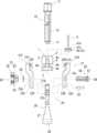
センタープレート1は棹状の部材で、中央に雌螺子孔5aが刻設された雌螺子部5と、雌螺子部5の両側から左右方向に伸びたガイド部2とで形成されている。
ガイド部2の縦断面は、図5に示すように、逆T字状に形成され、下面側の前後に膨出した幅広部分がガイドレール3である。雌螺子部5の雌螺子孔5aにセンターボルト10の軸部分15が螺進螺退可能に螺装されている。The
As shown in FIG. 5, the longitudinal section of the
ガイド部2の先端部分には、作動ワイヤ30を案内する移動補助部材40が設けられている。移動補助部材40は作動ワイヤ30をスムーズに案内して抵抗なく移動できるようにすることが出来ればどのようなものでもよいが、ここでは回転コマ41又は円弧状ガイド溝45を作動ワイヤ30の案内用の移動補助部材40としている。以下、回転コマ41(図10参照)を代表例として説明し、円弧状ガイド溝45を変形例として後述する(図11、図12参照)。 A
移動補助部材40が回転コマ41とした場合、図10に示すようにガイド部2の両先端部分でガイドレール3の直上に水平方向に開口する矩形の切り溝4がそれぞれ設けられ、この切り溝4の中央を上下に貫通する回転軸支持孔4hが上記先端部分に穿設されている。
回転コマ41は、背の低い円柱状のものでその全周に作動ワイヤ30を案内するガイド溝41aが形成され、中心に回転孔41hが穿設されている。この回転コマ41は、図7、図8に示すようにガイド部2の先端部分に設けられた切り溝4にそれぞれ嵌め込まれ、ガイド部2の先端部分に縦方向に穿設された回転軸支持孔4hに挿入された回転軸6に回転可能に取り付けられている。When the movement
The rotating top 41 has a short cylindrical shape, has a
図2、図7から分かるように、センタープレート1の雌螺子部5の前面から背面に至る前後幅Sは、後述する作動ワイヤ30の前後幅2W(前面側の作動ワイヤ30と背面側の作動ワイヤ30の幅)より大きい。それ故、作動ワイヤ30に干渉しないように、雌螺子部5の表・裏面には作動ワイヤ30の通り道に沿って大きく掘り込まれた逃げ溝5mが凹設されている。この逃げ溝5mはセンタープレート1の外周に巻設された作動ワイヤ30の保護としての役割も有する。 As can be seen from FIGS. 2 and 7, the front-to-back width S from the front to the back of the
爪アーム20は左右対称で、取付胴部21及びアーム部26とで構成されている。
取付胴部21は、図9、図10に示すように、前後半割りの胴部前部21Fと、これに対称な形状の胴部後部21Bとで構成される。The
As shown in FIGS. 9 and 10, the
胴部前部21Fと胴部後部21Bの内面上部には、レール溝22F・22Bがそれぞれ設けられ、更に胴部前部21Fと胴部後部21Bの内面下部には、レール溝22F・22Bから胴部前部21Fと胴部後部21Bの下端に至る縦方向のアーム上部収納溝23F・23Bが掘設されている。
センタープレート1のガイドレール3はレール溝22F・22Bにて前後から挟み込まれ、アーム部26の上部は胴部前部21Fのアーム上部収納溝23Fと胴部後部21Bのアーム上部収納溝23Bに挟まれて保持される。胴部前部21Fと胴部後部21Bのガイドレール3への固定は後述するロック部材50によって行われる。
The
胴部前部21Fと胴部後部21Bのレール溝22F・22Bの上部において、レール溝22F・22Bと平行に設置された作動ワイヤ30の通り路となる通過路21hが形成されている。通過路21hは胴部前部21F及び胴部後部21Bの右側面から左側面に貫通している。
通過路21hは図10では、胴部前部21F及び胴部後部21Bの上部を左右に貫通する貫通孔であるが、勿論、これに限られず、図13のように凹溝としてもよい。ここでは、通過路21hの代表例として貫通孔を用いる。この通過路21hの孔径は、作動ワイヤ30の直径の2倍をわずかに超える大きさである。(通過路21hが凹溝の場合、溝幅は作動ワイヤ30の直径をわずかに超える大きさであり、止め螺子21tで作動ワイヤ30が固定されることになる。)At the upper part of the
In FIG. 10, the
一方の爪アーム20Lの胴部前部21Fには、その上面から通過路21hに至る螺子孔21nが1乃至複数個設けられ、止め螺子21tが螺入されている。この部分が一方のワイヤ取付部24Lである(図1、図2)。
そして、他方の爪アーム20Rの胴部後部21Bには、その上面から通過路21hに至る螺子孔21nが1乃至複数個設けられ、止め螺子21tが螺入されている。この部分が一方のワイヤ取付部24Rである。そして、後述するように、作動ワイヤ30はワイヤ取付部24L・24Rで止め螺子21tにてロックされる。
これに対して、一方の爪アーム20Lの胴部後部21B、他方の爪アーム20Rの胴部前部21Fには螺子孔は設けられず、作動ワイヤ30は通過路21h内を移動することになる(図2)。The
The
On the other hand, no screw holes are provided in the
胴部前部21Fと胴部後部21B内面には、上記のように、レール溝22F・22Bの下方に縦方向で取付胴部21の下面に開口するアーム上部収納溝23F・23Bが形成されている。
胴部後部21Bのアーム上部収納溝23Bに合わせて後述するロック部材50の締付螺子55の回り止め孔23cが穿設され、回り止め孔23cの下方に支持ピン25が遊嵌される支持ピン遊嵌孔23dが穿設されている。回り止め孔23cは例えば四角形のような異形孔である。(勿論、回り止め孔23cは異形孔でなく、単なる丸孔として側面からセット螺子で締付螺子55を固定するようにしてもよい。)
これに対して胴部前部21Fのアーム上部収納溝23Fに合わせて後述するロック部材50の締付螺子55の雄螺子足58が挿入される締付螺子挿入孔23gが穿設され、締付螺子挿入孔23gの下方に支持ピン25の突出し部分が遊嵌される支持ピン遊嵌孔23hが穿設されている。As described above, arm
A support pin in which a
On the other hand, a tightening
アーム部26は、アーム本体27と爪部28とで構成されている。アーム本体27は断面矩形の棒状の部分で、下端に内側に向けて爪部28が設けられ、全体としてL形又は逆L形をしている。(爪部28の方向は、左右のアーム部26を交換することで外側に反転できる。これにより、引抜対象物Cの内周縁に爪部28を係止して引き抜くことが出来る(図示せず)。)
アーム本体27の上部にはロック部材50の締付螺子55の雄螺子足58が挿通される締付螺子挿通孔27kが穿設され、その下部にはアーム部26を支持するための支持ピン25が固定される支持ピン固定孔27hが穿設されている。この支持ピン固定孔27hには支持ピン25が圧入固定或いはねじ固定され、固定孔27hから前後に突き出している。The
A tightening
アーム本体27の上部には、胴部前部21Fと胴部後部21Bのアーム上部収納溝23F・23Bが前後からそれぞれ嵌め込まれており、支持ピン25の突き出し部分が胴部前部21Fと胴部後部21Bの支持ピン遊嵌孔23h・23dに遊嵌され、挿脱方向及び回転方向に移動可能に挿入されている。 Arm
ロック部材50は、爪固定ノブ51と締付螺子55とで構成されている。爪固定ノブ51は、ハンドル52と、ハンドル52の内面に突設された突起部53とで構成され、突起部53の内面側に開口し、ハンドル52の外面方向に向けて雌ネジ穴54が螺設されている。 The
締付螺子55は、半球状の頭部56、頭部56の平面部分に設けられた断面異形(図は正方形)の回り止め基部57、及び回り止め基部57から突出した雄螺子足58とで構成されている。
締付螺子55は、胴部後部21Bの断面異形(図は正方形)の回り止め孔23cからアーム本体27の締付螺子挿通孔27kを通り、胴部前部21Fの丸孔の締付螺子挿入孔23gに挿通され、スプリングワッシャ59を介して爪固定ノブ51の脚固定用の雌ネジ穴54に螺入されている。
締付螺子55は、その回り止め基部57が胴部後部21Bの回り止め孔23cに嵌り込んでおり、締付螺子55の回転が規制されている。The tightening
The tightening
The locking
なお、ロック部材50を締め付けて半割りの胴部前部21F及び胴部後部21Bがガイドレール3を前後から挟み付け、爪アーム20をガイド部2に固定する関係上、胴部前部21F及び胴部後部21Bの内面に掘設されたアーム上部収納溝23F・23Bの深さの合計はアーム本体27の前後幅より小さく、胴部前部21F及び胴部後部21Bの内面の間には締め付け状態で隙間Hが設けられるようになっている(図8)。 In addition, since the locking
作動ワイヤ30は、例えば、スチールやステンレス線の撚り線で構成されている。図1及び図2から分かるように、作動ワイヤ30は、図1の左側の爪アーム20Lの胴部前部21Fの通過路21hに挿通され、左側のガイド部2Lの先端に回転自在に装着された回転コマ41のガイド溝41aに嵌め込まれ、センタープレート1の背面に回り、左側の爪アーム20Lの胴部後部21Bの通過路21hに挿通され、センタープレート1の雌螺子部5の背面側の逃げ溝5mを通り、右側の爪アーム20Rの胴部後部21Bの通過路21hに挿通され、右側のガイド部2Rの先端に回転自在に装着された回転コマ41のガイド溝41aに嵌め込まれ、センタープレート1の前面に回り、右側の爪アーム20Rの胴部前部21Fの通過路21hに挿通され、センタープレート1の雌螺子部5の前面側の逃げ溝5mを通り、センタープレート1を一周して左側の爪アーム20Lの胴部前部21Fの通過路21hに挿通される。左側の爪アーム20Lの胴部前部21Fの通過路21hでは作動ワイヤ30が重複して挿通される。 The
そして、左側の爪アーム20Lの胴部前部21Fと、右側の爪アーム20Rの胴部後部21Bのワイヤ取付部24L・24Rに止め螺子21tが螺入され、止め螺子21tによって作動ワイヤ30が、左側の爪アーム20Lの胴部前部21Fと、右側の爪アーム20Rの胴部後部21Bとに一体固定される。一方、左側の爪アーム20Lの胴部後部21Bと、右側の爪アーム20Rの胴部前部21Fは止め螺子21tが用いられず、作動ワイヤ30はこれらの通過路21hを自由に移動する。 Then, the
ここで、移動補助部材40と通過路21hとの関係を図7、図8に従って説明する。移動補助部材40(ここでは回転コマ41)のガイド溝41aの半径をRとする。そしてセンタープレート1の前後幅方向の中心線CLからワイヤ取付部24の通過路21hの中心までの幅をWとする。本実施例では、前記幅Wが半径Rより大きく形成され(幅W>半径R)、移動補助部材40(回転コマ41)のガイド溝41aにおける、作動ワイヤ30がガイド溝41aから離れる点から通過路21hの入口までの間では、ガイド部2に対して広がる方向に傾斜している。これにより作動ワイヤ30の長さが、左右の回転コマ41間に直線状に張った状態で掛け回した状態に比べて作動ワイヤ30の長さに比べて長くなり、作動ワイヤ30に傾斜分の余裕が発生する。その結果、作動ワイヤ30に無駄な張力が発生せず、左右の爪アーム20L・20Rの円滑な開閉動作が可能となる。換言すれば、上記のように作動ワイヤ30を左右の回転コマ41間に直線状に張った状態で掛け回すと、作動ワイヤ30に無駄な張力が発生して回転コマ41が回転しにくくなり(移動補助部材40が円弧状ガイド溝45の場合は作動ワイヤ30が滑りにくくなり)、左右の爪アーム20L・20Rの円滑な開閉動作が出来なくなる。 Here, the relationship between the
上記構成によれば、本発明のギアプーラAは、従来のギアプーラと同様にシャフトBから引抜対象物C(ギヤやプーリー)を一人で簡単に取り外すことができる。
まず、左右の爪アーム20L・20Rのロック部材50L・50Rを緩めて左右の爪アーム20L・20Rがガイドレール3L・3Rに沿って自在にスライド開閉出来る状態にする。続いてセンターボルト10を回し、引抜対象物Cの厚みに対して十分に螺退させる。According to the above configuration, the gear puller A of the present invention allows one person to easily remove the object C (gear or pulley) from the shaft B, similar to the conventional gear puller.
First, the
この状態で、一方の手で一方の爪アーム20Lを外側に移動させる。この一方の爪アーム20Lの胴部前部21Fに作動ワイヤ30が固定され、センタープレート1の周囲を取り巻くように巻設された作動ワイヤ30は他方の爪アーム20Rの胴部後部21Bに固定されているため、一方の爪アーム20Lの外側への移動に合わせて他方の爪アーム20Rも作動ワイヤ30に引っ張られて外側方向に等距離だけ移動する。左右の爪部28L・28Rの間隔が引抜対象物Cの直径より大きくなった処で引抜対象物Cを跨ぐようにギアプーラAをセットする。 In this state, use one hand to move one
次に、引抜対象物Cの直径に合わせて左右の爪アーム20L・20Rを均等に閉じ、左右の爪部28L・28Rを引抜対象物Cの外周下面に係止する。左右の爪アーム20L・20Rは作動ワイヤ30により等距離で閉方向に移動するので、左右の爪部28L・28Rを引抜対象物Cの外周下面に係止した状態では、センターボルト10は自動的にシャフトBに軸合せ状態となる。
この状態で、センターボルト10を回して螺進させ、先端のセンタ突起17をシャフトBのセンタ穴に嵌め込む。この状態までギアプーラAをセットすると、左右のロック部材50を締め込んで取付胴部21をガイドレール3に挟持固定すると共に取付胴部21にアーム部26を固定する。同時にアーム部26の上部も取付胴部21に挟持固定される。これにより、センタープレート1と左右の爪アーム20L・20Rとは一体化される。Next, the left and right claw
In this state, the
続いて、センターボルト10の回転操作ヘッド11に六角レンチやスパナなどの回転作動工具60を嵌め込み、これを回転させて更にセンターボルト10を螺進させる。センターボルト10の螺進に合わせて左右の爪アーム20がセンタープレート1と共に均等に引き上げられ、引抜対象物CがシャフトBから引き抜かれる。この間、センターボルト10のセンタ突起17によって、センターボルト10とシャフトBの軸芯は一致しており、センターボルト10がシャフトBからずれることはないし、左右の爪アーム20の爪部28が引抜対象物Cから離脱するようなことがない。 Subsequently, a
引抜対象物Cの引き抜きが終了すると、ギアプーラAから引抜対象物Cが取り外され、ギアプーラAは所定の場所に収納されることになる。本発明のギアプーラAの作動ワイヤ30は、作業の開始から収納まで外部に露出しているが、センタープレート1の最も太い部分である雌螺子部5では、逃げ溝5m内に嵌り込んでいて作業中に障害物に接触することがなく、また、雌螺子部5と回転コマ41との間では、幅広いガイドレール3に沿って伸びていて障害物に接触する機会が殆どなく、細いワイヤでありながら、損傷するようなことがない。仮に損傷しても止め螺子21tを緩めればすぐ交換できるので、作業に支障を与えるようなことがない。
上記の操作はギアプーラAが作動ワイヤ30を使用するものであって軽量且つ小型であるため、一人の作業で簡単に行う事が出来る。When the pulling of the object C is completed, the object C is removed from the gear puller A, and the gear puller A is stored in a predetermined location. The
The above operation can be easily performed by one person because the gear puller A uses the
図11、図12は、移動補助部材40の別の例で、回転コマ41に代えて、切り溝4の開口端を凸円弧状に形成した例である。その半径を上記同様Rとする。切り溝4の凸円弧状の面は滑らかな面で形成され、作動ワイヤ30はこの面を滑動することになる。 11 and 12 show another example of the
図13は作動ワイヤ30が通過する通過路21hの別の例で、貫通孔の代わりに胴部前部21Fの前面から背面側に向かって掘り込まれた溝、胴部後部21Bの背面から前面側に向かって掘り込まれた溝で通過路21hが形成された例である。 FIG. 13 shows another example of the
A:ギアプーラ、B:シャフト、C:引抜対象物、CL:中心線、H:隙間、R:回転コマ(円弧状ガイド溝)の半径、幅S:雌螺子部、W:中心線からワイヤ取付部までの幅、2W:作動ワイヤの前後幅、1:センタープレート、2(2L・2R):ガイド部、3(3L・3R):ガイドレール、4:切り溝、4h:回転軸支持孔、5:雌螺子部、5a:雌螺子孔、5m:逃げ溝、6:回転軸、10:センターボルト、11:回転操作ヘッド、15:軸部分、17:センタ突起、20(20L・20R):爪アーム、21:取付胴部、21B:胴部後部、21F:胴部前部、21h:通過路、21n:螺子孔、21t:止め螺子、22B・22F:レール溝、23B・23F:アーム上部収納溝、23c:回り止め孔、23d:支持ピン遊嵌孔、23g:締付螺子挿入孔、23h:支持ピン遊嵌孔、24(24L・24R):ワイヤ取付部、25:支持ピン、26:アーム部、27:アーム本体、27h:支持ピン固定孔、27k:締付螺子挿通孔、28:爪部、30:作動ワイヤ、40:移動補助部材、41:回転コマ、41a:ガイド溝、41h:回転孔、45:円弧状ガイド溝、50(50L・50R):ロック部材、51:爪固定ノブ、52:ハンドル、53:突起部、54:雌ネジ穴、55:締付螺子、56:頭部、57:回り止め基部、58:雄螺子足、59:スプリングワッシャ、60:回転駆動工具
A: Gear puller, B: Shaft, C: Object to be pulled out, CL: Center line, H: Gap, R: Radius of rotating piece (arc-shaped guide groove), Width S: Female thread, W: Wire installation from center line Width to section, 2W: Front and rear width of actuation wire, 1: Center plate, 2 (2L/2R): Guide section, 3 (3L/3R): Guide rail, 4: Cut groove, 4h: Rotating shaft support hole, 5: Female thread part, 5a: Female thread hole, 5m: Relief groove, 6: Rotating shaft, 10: Center bolt, 11: Rotating operation head, 15: Shaft part, 17: Center protrusion, 20 (20L/20R): Claw arm, 21: Mounting body, 21B: Rear body, 21F: Front body, 21h: Passage path, 21n: Screw hole, 21t: Set screw, 22B/22F: Rail groove, 23B/23F: Upper arm Storage groove, 23c: Detent hole, 23d: Support pin loose fit hole, 23g: Tightening screw insertion hole, 23h: Support pin loose fit hole, 24 (24L/24R): Wire attachment part, 25: Support pin, 26 : Arm part, 27: Arm body, 27h: Support pin fixing hole, 27k: Tightening screw insertion hole, 28: Claw part, 30: Operating wire, 40: Movement auxiliary member, 41: Rotating piece, 41a: Guide groove, 41h: Rotation hole, 45: Arc-shaped guide groove, 50 (50L/50R): Lock member, 51: Claw fixing knob, 52: Handle, 53: Projection, 54: Female screw hole, 55: Tightening screw, 56 : Head, 57: Anti-rotation base, 58: Male screw foot, 59: Spring washer, 60: Rotary drive tool
Claims (6)
Translated fromJapanese前記センターボルト10が螺進螺退可能に螺挿された雌螺子部5と、前記雌螺子部5から前記センターボルト10に対して左右に伸びたガイド部2とを含むセンタープレート1と、
前記ガイド部2にスライド可能に取り付けられ、且つ前記センターボルト10のセンタ突起17と同方向に伸び、シャフトBから抜き出される引抜対象物Cを係止する爪部28が、その先端に設けられた左右一対の爪アーム20と、
前記左右のガイド部2の先端部分を通り、前記センタープレート1の前面から背面に至るように配設されて前記センタープレート1の周囲を取り巻くように設けられた作動ワイヤ30とで構成され、
前記作動ワイヤ30は、一方の爪アーム20Lの、前記センタープレート1の前面側に設けられたワイヤ取付部24Lに固定され、且つ、他方の爪アーム20Rの、前記センタープレート1の背面側に設けられたワイヤ取付部24Rに固定されていることを特徴とするギアプーラ。A rotary operation head 11 is provided at one end, a male screw is carved on the outer periphery of a shaft portion 15 that continues to the rotary operation head 11, and a center protrusion that comes into contact with the end surface of the shaft B on which the object C to be pulled is fitted is fitted at the other end. a center bolt 10 provided with 17;
A center plate 1 including a female screw portion 5 into which the center bolt 10 is screwed in such a manner that the center bolt 10 can be screwed forward and backward, and a guide portion 2 extending from the female screw portion 5 to the left and right with respect to the center bolt 10;
A claw part 28 is slidably attached to the guide part 2, extends in the same direction as the center protrusion 17 of the center bolt 10, and locks the object C to be pulled out from the shaft B. a pair of left and right claw arms 20;
an actuating wire 30 that passes through the tip portions of the left and right guide portions 2 and extends from the front surface to the back surface of the center plate 1 so as to surround the center plate 1;
The actuation wire 30 is fixed to a wire attachment portion 24L provided on the front side of the center plate 1 of one claw arm 20L, and is provided on the back side of the center plate 1 of the other claw arm 20R. A gear puller characterized in that it is fixed to a wire attachment part 24R.
The front-to-back width S from the front to the back of the female threaded portion 5 of the center plate 1 is larger than the front-to-back width 2W of the actuation wire 30 passing through the front and back surfaces of the center plate 1, and The gear puller according to the present invention as claimed in claim 1 or 2, characterized in that an escape groove (5m) through which the operating wire (30) passes is provided on the back surface.
Priority Applications (1)
| Application Number | Priority Date | Filing Date | Title |
|---|---|---|---|
| JP2022068882AJP2023158856A (en) | 2022-04-19 | 2022-04-19 | gear puller |
Applications Claiming Priority (1)
| Application Number | Priority Date | Filing Date | Title |
|---|---|---|---|
| JP2022068882AJP2023158856A (en) | 2022-04-19 | 2022-04-19 | gear puller |
Publications (1)
| Publication Number | Publication Date |
|---|---|
| JP2023158856Atrue JP2023158856A (en) | 2023-10-31 |
Family
ID=88513736
Family Applications (1)
| Application Number | Title | Priority Date | Filing Date |
|---|---|---|---|
| JP2022068882APendingJP2023158856A (en) | 2022-04-19 | 2022-04-19 | gear puller |
Country Status (1)
| Country | Link |
|---|---|
| JP (1) | JP2023158856A (en) |
- 2022
- 2022-04-19JPJP2022068882Apatent/JP2023158856A/enactivePending
Similar Documents
| Publication | Publication Date | Title |
|---|---|---|
| US5105648A (en) | Molded lightweight handtool with structural insert | |
| US3383963A (en) | Pivoted gripping tool having removable swivelly mounted jaws | |
| US4133519A (en) | Vise with selectable jaw faces | |
| JP5133115B2 (en) | Chain cutting and connecting device | |
| DE102012100001B4 (en) | Adjustable wrench | |
| US6186033B1 (en) | Multi-positional turning tool | |
| US10010954B2 (en) | Cutter | |
| US9099853B2 (en) | Cable-ripping tool | |
| DE10036171A1 (en) | Clamping device for a saw blade | |
| KR20090127894A (en) | Clamping device having a pivoting handling arm and equipment comprising the device | |
| DE4429408C2 (en) | Jigsaw assembly with improved clamping mechanism | |
| US5004020A (en) | Wire twisting apparatus | |
| CN1440257A (en) | Safety ratchet mechanism | |
| JP2000005930A (en) | Chainsaw guide bar | |
| US4880038A (en) | Wire twisting apparatus | |
| US2300087A (en) | Electric marine cable stripper | |
| EP1602452A3 (en) | Shank for a percussive and/or rotary tool | |
| US4796877A (en) | Workpiece holder and saw guide device | |
| JP2023158856A (en) | gear puller | |
| DE2138708B2 (en) | Assembly tool for external circlips | |
| US2622389A (en) | Link pivot removing tool | |
| JP4102178B2 (en) | Cable stripping tool | |
| AU645499B2 (en) | Rapid jaw adjustment for tools and the like | |
| JP2020044645A (en) | Cutting tool | |
| JP4422994B2 (en) | Grabber |
Legal Events
| Date | Code | Title | Description |
|---|---|---|---|
| A621 | Written request for application examination | Free format text:JAPANESE INTERMEDIATE CODE: A621 Effective date:20250404 | |
| A521 | Request for written amendment filed | Free format text:JAPANESE INTERMEDIATE CODE: A523 Effective date:20250422 | |
| RD02 | Notification of acceptance of power of attorney | Free format text:JAPANESE INTERMEDIATE CODE: A7422 Effective date:20250422 |