JP2023158459A - Display device, program, display method, display system - Google Patents
Display device, program, display method, display systemDownload PDFInfo
- Publication number
- JP2023158459A JP2023158459AJP2022068317AJP2022068317AJP2023158459AJP 2023158459 AJP2023158459 AJP 2023158459AJP 2022068317 AJP2022068317 AJP 2022068317AJP 2022068317 AJP2022068317 AJP 2022068317AJP 2023158459 AJP2023158459 AJP 2023158459A
- Authority
- JP
- Japan
- Prior art keywords
- display state
- display
- display device
- processing unit
- state data
- Prior art date
- Legal status (The legal status is an assumption and is not a legal conclusion. Google has not performed a legal analysis and makes no representation as to the accuracy of the status listed.)
- Pending
Links
Images


Classifications
- G—PHYSICS
- G06—COMPUTING OR CALCULATING; COUNTING
- G06F—ELECTRIC DIGITAL DATA PROCESSING
- G06F3/00—Input arrangements for transferring data to be processed into a form capable of being handled by the computer; Output arrangements for transferring data from processing unit to output unit, e.g. interface arrangements
- G06F3/01—Input arrangements or combined input and output arrangements for interaction between user and computer
- G06F3/048—Interaction techniques based on graphical user interfaces [GUI]
- G06F3/0487—Interaction techniques based on graphical user interfaces [GUI] using specific features provided by the input device, e.g. functions controlled by the rotation of a mouse with dual sensing arrangements, or of the nature of the input device, e.g. tap gestures based on pressure sensed by a digitiser
- G06F3/0488—Interaction techniques based on graphical user interfaces [GUI] using specific features provided by the input device, e.g. functions controlled by the rotation of a mouse with dual sensing arrangements, or of the nature of the input device, e.g. tap gestures based on pressure sensed by a digitiser using a touch-screen or digitiser, e.g. input of commands through traced gestures
- G06F3/04883—Interaction techniques based on graphical user interfaces [GUI] using specific features provided by the input device, e.g. functions controlled by the rotation of a mouse with dual sensing arrangements, or of the nature of the input device, e.g. tap gestures based on pressure sensed by a digitiser using a touch-screen or digitiser, e.g. input of commands through traced gestures for inputting data by handwriting, e.g. gesture or text
- G—PHYSICS
- G06—COMPUTING OR CALCULATING; COUNTING
- G06F—ELECTRIC DIGITAL DATA PROCESSING
- G06F3/00—Input arrangements for transferring data to be processed into a form capable of being handled by the computer; Output arrangements for transferring data from processing unit to output unit, e.g. interface arrangements
- G06F3/01—Input arrangements or combined input and output arrangements for interaction between user and computer
- G06F3/048—Interaction techniques based on graphical user interfaces [GUI]
- G06F3/0487—Interaction techniques based on graphical user interfaces [GUI] using specific features provided by the input device, e.g. functions controlled by the rotation of a mouse with dual sensing arrangements, or of the nature of the input device, e.g. tap gestures based on pressure sensed by a digitiser
- G06F3/0488—Interaction techniques based on graphical user interfaces [GUI] using specific features provided by the input device, e.g. functions controlled by the rotation of a mouse with dual sensing arrangements, or of the nature of the input device, e.g. tap gestures based on pressure sensed by a digitiser using a touch-screen or digitiser, e.g. input of commands through traced gestures
- G—PHYSICS
- G06—COMPUTING OR CALCULATING; COUNTING
- G06F—ELECTRIC DIGITAL DATA PROCESSING
- G06F3/00—Input arrangements for transferring data to be processed into a form capable of being handled by the computer; Output arrangements for transferring data from processing unit to output unit, e.g. interface arrangements
- G06F3/01—Input arrangements or combined input and output arrangements for interaction between user and computer
- G06F3/048—Interaction techniques based on graphical user interfaces [GUI]
- G06F3/0481—Interaction techniques based on graphical user interfaces [GUI] based on specific properties of the displayed interaction object or a metaphor-based environment, e.g. interaction with desktop elements like windows or icons, or assisted by a cursor's changing behaviour or appearance
- G06F3/0482—Interaction with lists of selectable items, e.g. menus
- G—PHYSICS
- G06—COMPUTING OR CALCULATING; COUNTING
- G06F—ELECTRIC DIGITAL DATA PROCESSING
- G06F3/00—Input arrangements for transferring data to be processed into a form capable of being handled by the computer; Output arrangements for transferring data from processing unit to output unit, e.g. interface arrangements
- G06F3/01—Input arrangements or combined input and output arrangements for interaction between user and computer
- G06F3/048—Interaction techniques based on graphical user interfaces [GUI]
- G06F3/0481—Interaction techniques based on graphical user interfaces [GUI] based on specific properties of the displayed interaction object or a metaphor-based environment, e.g. interaction with desktop elements like windows or icons, or assisted by a cursor's changing behaviour or appearance
- G06F3/0483—Interaction with page-structured environments, e.g. book metaphor
- G—PHYSICS
- G06—COMPUTING OR CALCULATING; COUNTING
- G06F—ELECTRIC DIGITAL DATA PROCESSING
- G06F3/00—Input arrangements for transferring data to be processed into a form capable of being handled by the computer; Output arrangements for transferring data from processing unit to output unit, e.g. interface arrangements
- G06F3/01—Input arrangements or combined input and output arrangements for interaction between user and computer
- G06F3/048—Interaction techniques based on graphical user interfaces [GUI]
- G06F3/0484—Interaction techniques based on graphical user interfaces [GUI] for the control of specific functions or operations, e.g. selecting or manipulating an object, an image or a displayed text element, setting a parameter value or selecting a range
- G06F3/04845—Interaction techniques based on graphical user interfaces [GUI] for the control of specific functions or operations, e.g. selecting or manipulating an object, an image or a displayed text element, setting a parameter value or selecting a range for image manipulation, e.g. dragging, rotation, expansion or change of colour
- G—PHYSICS
- G06—COMPUTING OR CALCULATING; COUNTING
- G06F—ELECTRIC DIGITAL DATA PROCESSING
- G06F3/00—Input arrangements for transferring data to be processed into a form capable of being handled by the computer; Output arrangements for transferring data from processing unit to output unit, e.g. interface arrangements
- G06F3/01—Input arrangements or combined input and output arrangements for interaction between user and computer
- G06F3/048—Interaction techniques based on graphical user interfaces [GUI]
- G06F3/0484—Interaction techniques based on graphical user interfaces [GUI] for the control of specific functions or operations, e.g. selecting or manipulating an object, an image or a displayed text element, setting a parameter value or selecting a range
- G06F3/04847—Interaction techniques to control parameter settings, e.g. interaction with sliders or dials
- G—PHYSICS
- G06—COMPUTING OR CALCULATING; COUNTING
- G06F—ELECTRIC DIGITAL DATA PROCESSING
- G06F3/00—Input arrangements for transferring data to be processed into a form capable of being handled by the computer; Output arrangements for transferring data from processing unit to output unit, e.g. interface arrangements
- G06F3/01—Input arrangements or combined input and output arrangements for interaction between user and computer
- G06F3/048—Interaction techniques based on graphical user interfaces [GUI]
- G06F3/0484—Interaction techniques based on graphical user interfaces [GUI] for the control of specific functions or operations, e.g. selecting or manipulating an object, an image or a displayed text element, setting a parameter value or selecting a range
- G06F3/0485—Scrolling or panning
- G—PHYSICS
- G06—COMPUTING OR CALCULATING; COUNTING
- G06F—ELECTRIC DIGITAL DATA PROCESSING
- G06F2203/00—Indexing scheme relating to G06F3/00 - G06F3/048
- G06F2203/048—Indexing scheme relating to G06F3/048
- G06F2203/04808—Several contacts: gestures triggering a specific function, e.g. scrolling, zooming, right-click, when the user establishes several contacts with the surface simultaneously; e.g. using several fingers or a combination of fingers and pen
- G—PHYSICS
- G06—COMPUTING OR CALCULATING; COUNTING
- G06F—ELECTRIC DIGITAL DATA PROCESSING
- G06F40/00—Handling natural language data
- G06F40/10—Text processing
- G06F40/166—Editing, e.g. inserting or deleting
- G—PHYSICS
- G06—COMPUTING OR CALCULATING; COUNTING
- G06F—ELECTRIC DIGITAL DATA PROCESSING
- G06F40/00—Handling natural language data
- G06F40/10—Text processing
- G06F40/197—Version control
Landscapes
- Engineering & Computer Science (AREA)
- General Engineering & Computer Science (AREA)
- Theoretical Computer Science (AREA)
- Human Computer Interaction (AREA)
- Physics & Mathematics (AREA)
- General Physics & Mathematics (AREA)
- User Interface Of Digital Computer (AREA)
Abstract
Description
Translated fromJapanese本発明は、表示装置、プログラム、表示方法、及び表示システムに関する。 The present invention relates to a display device, a program, a display method, and a display system.
タッチパネル式のディスプレイにユーザーが専用の電子ペンや指などで描画した手書きデータを表示する電子黒板などの表示装置が知られている。従来のホワイトボードと異なり手書きデータを電子データで保存したり、PC(Personal Computer)等の外部装置と接続して外部装置が表示する資料の画像を表示装置が表示したりすることができる。 Display devices such as electronic blackboards are known that display handwritten data drawn by a user using a dedicated electronic pen or finger on a touch panel display. Unlike conventional whiteboards, handwritten data can be saved as electronic data, and when connected to an external device such as a PC (Personal Computer), the display device can display images of materials displayed by the external device.
表示装置に、Undo/Redo機能が備えられる場合がある(例えば、特許文献1参照。)。Undo/Redo機能は、編集中に一操作前の状態に戻す、操作を進めることをいう。特許文献1には、表示装置が意図せず終了した際に、編集時点での表示装置の操作履歴を復元する技術が開示されている。 A display device may be equipped with an Undo/Redo function (for example, see Patent Document 1). The Undo/Redo function is used to return to the state before an operation or to proceed with an operation during editing.
しかしながら、従来の技術は、Undo/Redo操作により所望の表示状態を復元するには、操作した回数分のUndo/Redo操作を実行しなくてはならないという問題があった。すなわち、表示装置では一つのストロークが一回の操作で入力されるので、例えば3つのストロークを有する「あ」という手書きデータを入力前に戻す又は再表示させるためには計3回のUndo/Redo操作が必要になる。 However, the conventional technology has a problem in that in order to restore the desired display state by the Undo/Redo operation, it is necessary to perform the Undo/Redo operation the same number of times as the Undo/Redo operation. In other words, since one stroke is input in one operation on a display device, for example, in order to return or redisplay handwritten data of ``a'' which has three strokes, Undo/Redo is required three times in total. operation is required.
また、複数の拠点からオンライン上でユーザーが表示装置を利用する場合、各拠点のユーザーが任意に手書きするため、必要となるUndo/Redo操作の回数はさらに増加することが予測される。 Furthermore, when users use a display device online from multiple locations, it is predicted that the number of Undo/Redo operations required will further increase because the users at each location will arbitrarily handwrite.
本発明は、上記課題に鑑み、所望の表示状態を復元することができる表示装置を提供することを目的とする。 In view of the above problems, an object of the present invention is to provide a display device that can restore a desired display state.
本発明は、オブジェクトを表示する表示装置であって、表示されている前記オブジェクトの表示状態データを条件が満たされるごとに保存する表示状態保存処理部と、前記表示状態データの選択を受け付ける操作受付部と、前記操作受付部が選択を受け付けた前記表示状態データに基づいて前記オブジェクトの表示状態を復元する復元処理部と、を有することを特徴とする。 The present invention provides a display device that displays an object, including a display state storage processing unit that saves display state data of the displayed object every time a condition is satisfied, and an operation reception that accepts selection of the display state data. and a restoration processing section that restores the display state of the object based on the display state data whose selection has been accepted by the operation reception section.
所望の表示状態を復元することができる表示装置を提供することができる。 A display device that can restore a desired display state can be provided.
以下、本発明を実施するための形態の一例として、表示装置と表示装置が行う表示方法について実施例を挙げながら説明する。 DETAILED DESCRIPTION OF THE PREFERRED EMBODIMENTS Hereinafter, as an example of a mode for carrying out the present invention, a display device and a display method performed by the display device will be described with reference to examples.
<本実施形態の動画の保存方法を概略>
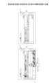
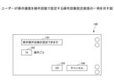
まず、図1を参照して、表示装置2がオブジェクトの表示状態を復元する方法の概略を説明する。図1は、本実施形態の表示装置2が表示状態を復元する操作の概略を説明する図である。図1(a)は、時系列復元モードの画面例を示す。過去のある時点の表示状態に戻したいユーザーは時系列復元モードに移行させるためボタンを押下する。時系列復元モードでは、過去の異なる時刻における表示状態を表す複数の画像がスライド可能に表示される。この画像を以下、サムネイルという。ユーザーがサムネイル101を左右にスライドさせると、スライド方向に応じて過去又は未来の表示状態のサムネイル101が表示される。スライド可能に表示されるサムネイル101は例えば一定時間ごとに自動的に保存されたオブジェクトの表示状態の画像である。<Outline of how to save videos in this embodiment>
First, a method for the
ユーザーが任意のサムネイル101を選択すると、図1(b)に示すように、表示装置2は選択されたサムネイル101に対応する表示状態でオブジェクトを表示する。すなわち、表示装置2は過去のある時点の表示状態を復元する。 When the user selects an
このように、本実施形態の表示装置2は、ある時点の表示状態に戻すために従来では操作回数に応じたUndo/Redoを必要とするのに対し、少ない操作回数(最小一操作)で復元できる。すなわち、表示装置2は、ユーザーの操作性を向上できる。 In this way, the
<用語について>
入力手段とはタッチパネルに座標を指定して手書きが可能な手段であればよい。例えば、電子ペン、人の指や手、棒状部材などがある。<About terms>
The input means may be any means that allows handwriting by specifying coordinates on a touch panel. Examples include an electronic pen, a human finger or hand, and a rod-shaped member.
ユーザーがディスプレイに入力手段を押しつけてから連続的に移動させた後、ディスプレイから離すという一連の操作をストロークという。ストロークは、ディスプレイに接触することなく、ユーザーの動きを追跡することを含む。この場合、表示装置は、例えばマウスやポインティングデバイスを使用して、ユーザーのジェスチャー、ユーザーの手または足によるボタンの押下、または他の方法で、ストロークを開始させてもよい。さらに、ユーザーは、同じまたは異なるジェスチャー、ボタンを離す、またはマウスやポインティングデバイスを使用して、ストロークを終了させてもよい。 A series of operations in which the user presses an input device against the display, continuously moves it, and then releases it from the display is called a stroke. Stroking involves tracking the user's movements without touching the display. In this case, the display device may initiate a stroke by a user's gesture, by pressing a button with the user's hand or foot, or in some other way, for example using a mouse or pointing device. Additionally, the user may terminate the stroke using the same or a different gesture, releasing a button, or using a mouse or pointing device.
ストロークデータとは、入力手段により入力される座標の軌跡に基づいてディスプレイに表示される情報である。ストロークデータは適宜、補間されてよい。手書きデータとは、1つ以上のストロークデータを有するデータである。手書き入力とは、ユーザーによって、手書きデータが入力されることを示している。手書き入力は、タッチインターフェース、電子ペンやスタイラスなどの触覚オブジェクト、またはユーザーの体を使って実行されてもよい。また、手書き入力は、ジェスチャーベースの入力、手の動きの追跡入力、またはユーザーによる他のタッチフリー入力など、他のタイプの入力を介して実行されてもよい。本発明の実施形態では、手書き入力および手書き入力データに言及するが、他の形態の手書き入力が利用されてもよい。 Stroke data is information displayed on a display based on a trajectory of coordinates input by an input means. Stroke data may be interpolated as appropriate. Handwritten data is data that includes one or more stroke data. Handwritten input indicates that handwritten data is input by the user. Handwriting input may be performed using a touch interface, a tactile object such as an electronic pen or stylus, or the user's body. Handwriting input may also be performed via other types of input, such as gesture-based input, hand movement tracking input, or other touch-free input by the user. Although embodiments of the invention refer to handwritten input and handwritten input data, other forms of handwritten input may be utilized.
ストロークデータに基づいてディスプレイに表示される表示物をオブジェクトという。オブジェクトとは対象という意味であるが、本実施形態では表示対象などの意味である。ストロークデータが手書き認識して変換されたオブジェクトには、テキストの他、「済」などの決まった文字やマークとして表示されるスタンプ、円や星などの図形、直線等も含まれてよい。テキストとは主に1つ以上の文字を含む文字列(文字コード)であり、数字、記号なども含む。テキストを文字列という場合がある。 An object displayed on a display based on stroke data is called an object. The term "object" means a target, and in this embodiment, it means a display target. Objects converted by handwriting recognition of stroke data may include, in addition to text, fixed characters such as "done", stamps displayed as marks, figures such as circles and stars, straight lines, and the like. Text is a character string (character code) that mainly includes one or more characters, and also includes numbers, symbols, etc. Text is sometimes called a string.
表示状態とは、ディスプレイ又は表示装置の画面において表示されているオブジェクトの態様である。表示状態には、どのオブジェクトが表示されている、オブジェクトの位置、及び、オブジェクトの状態(ストロークの色、太さ、線種)などが含まれてよい。 The display state is the mode of an object being displayed on the screen of a display or display device. The display state may include which object is being displayed, the position of the object, the state of the object (stroke color, thickness, line type), and the like.
表示状態データは、表示状態が格納されたデータである。 The display state data is data in which display states are stored.
表示状態を復元するとは、オブジェクトを元の状態で表示することをいう。元の状態は保存されている表示状態データのオブジェクトリストにより定まる。元の状態は、更にRedoリスト又はUndoリストにより定まる場合もある。 Restoring the display state means displaying the object in its original state. The original state is determined by the object list of saved display state data. The original state may also be determined by a Redo list or an Undo list.
<システム構成例>
図2は、本実施形態の通信システムの全体構成図である。なお、図2では、説明を簡略化するために、2台の表示装置2a,2b及びこれに付随する電子ペン4a,4b等を示しているだけであって、3台以上の表示装置2や電子ペン等が利用されてもよい。<System configuration example>
FIG. 2 is an overall configuration diagram of the communication system of this embodiment. In addition, in FIG. 2, in order to simplify the explanation, only two
図2に示されているように、通信システム1は、複数の表示装置2a,2b、複数の電子ペン4a,4b、USBメモリ5a,5b、ノートPC(Personal Computer)6a,6b、テレビ(ビデオ)会議端末7a,7b、及びPC8を有する。また、表示装置2a,2b、及びPC8は、通信ネットワーク9を介して通信可能に接続されている。更に、複数の表示装置2a,2bには、それぞれディスプレイ3a,3bが設けられている。 As shown in FIG. 2, the
また、表示装置2aには、電子ペン4aによって生じたイベント(ディスプレイ3aに電子ペン4aのペン先、又は、電子ペン4aのペン尻のタッチ)による描画された画像を、ディスプレイ3aに表示させることができる。なお、電子ペン4aだけでなく、ユーザーの手Ha等によって生じたイベント(拡大、縮小、ページめくり等のジェスチャー)に基づいて、ディスプレイ3a上に表示されている画像を変更させることもできる。 Further, the
また、表示装置2aには、USBメモリ5aが接続可能であり、表示装置2aはUSBメモリ5aからPDF等の電子ファイルを読み出したり、表示装置2aはUSBメモリ5aに電子ファイルを記録したりすることができる。また、表示装置2aには、DisplayPort(登録商標)、DVI(Digital Visual Interface)、HDMI(High-Definition Multimedia Interface。登録商標)及びVGA(Video Graphics Array)等の規格による通信が可能なケーブル10a1を介して、ノートPC6aが接続されている。そして、表示装置2aは、ディスプレイ3aに対する接触によってイベントを発生させ、このイベントを示すイベント情報を、マウスやキーボード等の入力装置からのイベントと同様に、ノートPC6aに送信する。同じく、表示装置2aには、上記規格による通信が可能なケーブル10a2を介して、テレビ(ビデオ)会議端末7aが接続されている。なお、ノートPC6a、及びテレビ会議端末7aは、Bluetooth(登録商標)等の各種無線通信プロトコルに準拠した無線通信により、表示装置2aと通信してもよい。 Further, a
一方、表示装置2bが設置されている他の拠点では、上記と同様に、ディスプレイ3bを備えた表示装置2b、電子ペン4b、USBメモリ5b、ノートPC6b、テレビ会議端末7b、ケーブル10b1、ケーブル10b2が利用される。更に、ユーザーの手Hb等によって生じたイベントに基づいて、ディスプレイ3b上に表示されている画像を変更させることもできる。 On the other hand, at other bases where the
これにより、一の拠点で表示装置2aのディスプレイ3a上に描画された画像は、他の拠点で表示装置2bのディスプレイ3b上にも表示され、逆に他の拠点で表示装置2bのディスプレイ3b上に描画された画像は、一の拠点で表示装置2aのディスプレイ3a上に表示される。このように、通信システム1では、遠隔地において同じ画像を共有する遠隔共有処理を行うことができるため、遠隔地での会議等に用いると、非常に便利である。 As a result, an image drawn on the
なお、以下では、複数の表示装置2のうち任意の表示装置2を示す場合には「表示装置2」と示す。複数のディスプレイのうち任意のディスプレイを示す場合には「ディスプレイ3」と示す。複数の電子ペンのうち任意の電子ペンを示す場合には「電子ペン4」と示す。複数のUSBメモリのうち任意のUSBメモリを示す場合には「USBメモリ5」と示す。複数のノートPCのうち任意のノートPCを示す場合には「ノートPC6」と示す。複数のテレビ会議端末のうち任意のテレビ会議端末を示す場合には「テレビ会議端末7」と示す。また、複数のユーザーの手のうち任意の手を示す場合には「手H」と示す。複数のケーブルのうち任意のケーブルを示す場合には「ケーブル10」と示す。 In addition, below, when indicating
また、本実施形態では、表示装置2の一例として、電子黒板を説明するが、これに限るものではなく、表示装置2の他の例として、表示装置2は、電子看板(デジタルサイネージ)、スポーツや天気予報等で利用されるテレストレータ、又は、遠隔画像(映像)診断装置等であってもよい。また、外部装置の一例として、ノートPC6を説明するが、これに限るものではなく、外部装置の他の例として、外部装置は、デスクトップ型PCやタブレット型PC、PDA、デジタルビデオカメラ、デジタルカメラ、ゲーム機等の画像フレームを供給可能な端末であってもよい。更に、通信ネットワークには、インターネット、LAN(Local Area Network)、携帯電話通信網等が含まれる。また、本実施形態では、記録媒体の一例として、USBメモリを説明するが、これに限るものではなく、記録媒体の他の例として、記録媒体は、SDカード等の各種記録メディアであってもよい。 Further, in this embodiment, an electronic blackboard will be described as an example of the
<表示装置のハードウェア構成>
続いて、図3を用いて、本実施形態の表示装置2のハードウェア構成を説明する。なお、図3は、表示装置2のハードウェア構成図である。図3に示されているように、表示装置2は、CPU(Central Processing Unit)201、ROM(Read Only Memory)202、RAM(Random Access Memory)203、SSD(Solid State Drive)204、ネットワークI/F205、及び、外部機器接続I/F(Interface)206を備えている。<Hardware configuration of display device>
Next, the hardware configuration of the
これらのうち、CPU201は、表示装置2全体の動作を制御する。ROM202は、CPU201やIPL(Initial Program Loader)等のCPU201の駆動に用いられるプログラムを記憶する。RAM203は、CPU201のワークエリアとして使用される。 Among these, the
SSD204は、OSや表示装置2用のプログラム等の各種データを記憶する。このプログラムは汎用的なOS(Windows(登録商標)、Mac OS(登録商標)、Android(登録商標)、iOS(登録商標)等)を搭載した情報処理装置で動作するアプリケーションプログラムでもよい。したがって、表示装置2は、普段は汎用的な情報処理装置として利用されるが、ユーザーがアプリケーションプログラムを実行すると、表示装置2の専用機と同様、ユーザーが手書きすることができる。 The
ネットワークI/F205は、通信ネットワーク9との通信を制御する。外部機器接続I/F206は、各種の外部機器を接続するためのインターフェースである。この場合の外部機器は、例えば、USB(Universal Serial Bus)メモリ5、外付け機器(マイク240、スピーカ250、カメラ260)である。 Network I/
また、表示装置2は、キャプチャデバイス211、GPU212、ディスプレイコントローラ213、接触センサ214、センサコントローラ215、電子ペンコントローラ216、近距離通信回路219、及び近距離通信回路219のアンテナ219a、電源スイッチ222及び選択スイッチ類223を備えている。 The
これらのうち、キャプチャデバイス211は、外付けのノートPC6のディスプレイに対して映像情報を静止画又は動画として表示させる。GPU(Graphics Processing Unit)212は、グラフィクスを専門に扱う半導体チップである。ディスプレイコントローラ213は、GPU212からの出力画像をディスプレイ3等へ出力するために画面表示の制御及び管理を行う。接触センサ214は、ディスプレイ3上に電子ペン4やユーザーの手H等が接触したことを検知する。センサコントローラ215は、接触センサ214の処理を制御する。接触センサ214は、赤外線遮断方式による座標の入力及び座標の検出を行う。この座標の入力及び座標の検出する方法は、ディスプレイ3の上側両端部に設置された2つ受発光装置が、ディスプレイ3に平行して複数の赤外線を放射し、ディスプレイ3の周囲に設けられた反射部材によって反射されて、受光素子が放射した光の光路と同一の光路上を戻って来る光を受光する方法である。接触センサ214は、物体によって遮断された2つの受発光装置が放射した赤外線のIDをセンサコントローラ215に出力し、センサコントローラ215が、物体の接触位置である座標位置を特定する。電子ペンコントローラ216は、電子ペン4と通信することで、ディスプレイ3へのペン先のタッチやペン尻のタッチの有無を判断する。近距離通信回路219は、NFC(Near Field Communication)やBluetooth(登録商標)等の通信回路である。電源スイッチ222は、表示装置2の電源のON/OFFを切り換えるためのスイッチである。選択スイッチ類223は、例えば、ディスプレイ3の表示の明暗や色合い等を調整するためのスイッチ群である。 Among these, the
更に、表示装置2は、バスライン210を備えている。バスライン210は、図3に示されているCPU201等の各構成要素を電気的に接続するためのアドレスバスやデータバス等である。 Furthermore, the
なお、接触センサ214は、赤外線遮断方式に限らず、静電容量の変化を検知することにより接触位置を特定する静電容量方式のタッチパネルでもよい。接触センサ214は、対向する2つの抵抗膜の電圧変化によって接触位置を特定する抵抗膜方式のタッチパネルでもよい。接触センサ214は、接触物体が表示部に接触することによって生じる電磁誘導を検知して接触位置を特定する電磁誘導方式のタッチパネルでもよく、種々の検出手段を用いてもよい。また、電子ペンコントローラ216が、電子ペン4のペン先及びペン尻だけでなく、電子ペン4のユーザーが握る部分や、その他の電子ペンの部分のタッチの有無を判断するようにしてもよい。 Note that the
<機能について>
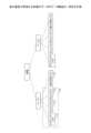
図4は、表示装置2の機能をブロック状に分けて説明する機能ブロック図の一例である。図4に示す表示装置2は、接触位置検出部12、描画データ生成部13、変換部14、表示制御部15、復元処理部16、ネットワーク通信部17、表示状態保存処理部18、操作受付部19、及び、記憶部20を有する。<About functions>
FIG. 4 is an example of a functional block diagram illustrating functions of the
表示装置2が有する各機能は、図3に示されている各構成要素のいずれかが、RAM203上に展開されたアプリケーションに従ったCPU201からの命令によって動作することで実現される機能又は手段である。 Each function that the
接触位置検出部12は、入力手段291(指や電子ペン等)がタッチパネルに接触した位置の座標を検出する。接触位置検出部12は、光を検知できないフォトトランジスタの数(光が遮断された幅)が所定の数以下の場合は、電子ペン4が接触したと判断し、所定の数より大きい場合はそれ以外の物体(例えば指)が接触したと判断する。 The contact
描画データ生成部13はユーザーが手書き入力し接触位置検出部12が検出した座標点列を補間することでストロークを生成する。 The drawing
変換部14は、手書きデータに文字認識処理を行い、手書きデータをテキストに変換する。テキストは、文字、数字、アルファベット、記号、三角や四角などの図形等も含まれる。 The
表示制御部15は、手書きデータ、テキスト、アプリのウィンドウ、PCのキャプチャ画像等のオブジェクトをディスプレイ3に表示するための制御を行う。表示制御部15は、ユーザーが操作するメニュー等も表示する。 The
ネットワーク通信部17は、LANやインターネット等のネットワークに接続して、他の表示装置2やPCとネットワークを介したデータの送受信を行う。 The
表示状態保存処理部18は、条件が満たされるごとに表示中のオブジェクトを復元するための表示状態データを個別に記憶部20に保存する。条件は、例えば一定時間ごと又は一定回数操作ごとであるが、詳細は後述する。 The display state
復元処理部16は、記憶部20に記憶されているある時点の表示状態データに基づいて、ある時点の表示状態をディスプレイ3に復元する。規定の間隔とは、例えば一定時間ごと又は一定回数操作ごとである。表示状態データは、ユーザーの操作で保存されてもよいし、不定期に保存されてもよい。 The
操作受付部19は、表示装置2に対するユーザー操作を受け付ける。例えば、操作受付部19は、表示状態を表すサムネイル101の選択を受け付ける。 The
<記憶部に保存されるデータ>
次に、図5~図7を参照して、記憶部20に保存される各種のデータについて説明する。図5は、表示装置2が管理する各種のデータのデータ構造を示す。表示装置2は会議ごとに表示状態データを管理する。会議とは、表示装置2の電源オン又は省エネモードからの復帰から、電源オフ又は省エネモードへの移行までをいう。会議という区切りでなく、ユーザーが指定するまでを1つの区切りとしてもよい。<Data saved in the storage unit>
Next, various types of data stored in the
記憶部20に保存される各種のデータはページごとに管理される。各ページが有するデータは、以下のとおりである。ページとは1つの平面的な表示範囲である。ページはディスプレイと同じサイズでもよいし、ページより大きい又は小さくてもよい。 Various data stored in the
・オブジェクトリスト111は、オブジェクトデータが、オブジェクトごとに時系列に保存されたリストである。オブジェクトデータは、オブジェクトの種類(ストローク、テキスト、スタンプなど)、オブジェクトのサイズ(Width, Height)、オブジェクトの位置情報(Top, Left、Right、Bottom)等を含む、オブジェクトを表示するためのデータである。 - The
・Undoリスト112は、操作履歴が時系列に保存されたリストである。 - The Undo
・Redoリスト113は、操作取消履歴が時系列に保存されたリストである。 - The
オブジェクトリスト111、Undoリスト112、及び、Redoリスト113を現在の表示状態115と称する。オブジェクトリスト111があれば、表示装置2はある時点の表示状態を復元できる。 The
・表示状態リスト114は、後述する表示状態データが時系列に保存されたリストである。詳細は図8にて説明する。 - The
図6は、オブジェクトリスト111のデータ構造を示す。オブジェクトリスト111は、ページに含まれるオブジェクトデータ121~124のリストである。図6に示すように、リストは、線形リストである。線形リストとは、データとポインタとが入ったノードと呼ばれる要素をポインタでつないだものである。したがって、オブジェクトが入力された順番も記録されている。オブジェクトデータが有する項目は以下のとおりである。
・idはオブジェクトの識別情報である。
・typeはオブジェクトの種類である。
・positionはオブジェクトの位置情報である。位置情報は、例えばオブジェクトの外接矩形が有する4つの頂点のうちいずれかの頂点の座標である。
・sizeはオブジェクトのサイズ(高さと幅)である。FIG. 6 shows the data structure of the
-id is object identification information.
・type is the type of object.
・Position is the position information of the object. The position information is, for example, the coordinates of one of the four vertices of the circumscribed rectangle of the object.
・Size is the size (height and width) of the object.
図7は、Undoリスト112及びRedoリスト113のデータ構造を示す。Undoリスト112は、ページに含まれる操作履歴131~134である。Redoリスト113はページに含まれる操作取消履歴であるが、データ構造はUndoリスト112と同じである。図7に示すように、Undoリスト112及びRedoリスト113は、線形リストである。Undoリスト112及びRedoリスト113が有する項目は以下のとおりである。
・operateは操作内容である。
・Target_idは、操作されたオブジェクトのidである。FIG. 7 shows the data structure of the Undo
・operate is the operation content.
-Target_id is the id of the operated object.
表示装置2は、これらの情報を参照及び操作することで、表示装置2の表示状態を記憶し、また、Undo/Redoの操作を実現している。例えば、図7の操作履歴134の操作内容は、Target_id =5のオブジェクトのdelete(削除)なので、ユーザーがUndo操作を行うと、表示装置2は削除したTarget_id =5のオブジェクトを再度、表示する。Target_id =5のオブジェクトはオブジェクトリスト111に含まれている。Undoリスト112から操作履歴134が削除され、Redoリスト113には操作取消履歴として操作履歴134が追加される。 By referring to and operating this information, the
また、図7の右から2つめの操作履歴133は、Target_id =5のオブジェクトのadd(追加)なので、ユーザーがUndo操作を行うと、表示装置2は追加したTarget_id =5のオブジェクトを非表示にする。Undoリスト112から操作履歴133が削除され、Redoリスト113には操作取消履歴として操作履歴133が追加される。 Furthermore, since the
この状態で、ユーザーがRedo操作を行うと、Redoリスト113にある最も新しい操作取消履歴(操作履歴133のこと)に基づいて、表示装置2はTarget_id =5のオブジェクトのadd(追加)を再実行し、Target_id =5のオブジェクトを表示する。Redoリスト113から操作取消履歴(操作履歴133)が削除され、Undoリスト112には操作履歴133が追加される。 In this state, when the user performs a Redo operation, the
<表示状態データの記憶>
続いて、図8を参照して、表示状態リスト114について説明する。図8は、表示状態リスト114を説明する図である。表示状態リスト114は、表示状態データを一定時間ごと又は一定回数操作ごとに記憶した表示状態データ141~143のリストである。表示状態データは、ある時点の表示状態を復元するためのデータである。各表示状態データ141~143は、以下の項目を有している。
・timeは表示状態データが保存された時刻である。時刻は絶対時刻でも電源オン又は省エネモードからの復帰からの経過時間でもよい。<Storing display status data>
Next, the
・time is the time when the display state data was saved. The time may be an absolute time or the elapsed time since the power was turned on or the energy saving mode was returned.
・objectlistは、ある時点(上記timeにおける)のオブジェクトリスト111である。 - objectlist is the
・undolistは、ある時点(上記timeにおける)のUndoリスト112である。表示状態データにUndoリスト112が含まれることで、ある時点の表示状態の復元後に、一操作単位でRedo操作が可能になる。
・redolistは、ある時点(上記timeにおける)のRedoリスト113である。表示状態データにRedoリスト113が含まれることで、ある時点の表示状態の復元後に、一操作単位でRedo操作が可能になる。- undolist is the Undo
- redolist is the
表示状態保存処理部18は、タイマーを利用し、一定時間ごとに、現時点での表示状態データを表示状態リスト114に追加する。一定回数操作ごとの場合、表示状態保存処理部18は、操作回数を記憶するカウンタを利用し、該当回数超過ごとに、現時点での表示状態データを表示状態リスト114に追加する(このとき、カウンタ初期化も行う)。 The display state
オブジェクトリスト111については、過去のオブジェクトが時系列に保存されるので、time10の表示状態データにはtime5の表示状態データが重複して含まれる。time15の表示状態データには、time5とtime10の表示状態データが重複して含まれる。Undoリスト112についても同様である。Redoリスト113については、表示状態データが保存された以降の操作内容が操作取消履歴として保存される。詳細は図10にて説明する。 Regarding the
なお、カウンタの対象となる操作は、例えば、ストローク追加、移動、削除など、オブジェクトリスト111への変更が発生するものが対象である。 Note that operations that are subject to the counter are operations that cause changes to the
<表示状態データの保存イメージ>
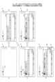
図9は、図8に示した、一定時間ごと又は一定回数操作ごとに保存される表示状態データを詳細に説明する図である。図9(a)は、ある時点におけるオブジェクトの表示例である。ユーザーが「あいう」を手書きした。<Image of saving display status data>
FIG. 9 is a diagram illustrating in detail the display state data shown in FIG. 8 that is saved every fixed time or every fixed number of operations. FIG. 9(a) is an example of how objects are displayed at a certain point in time. The user handwritten "Aiu".
図9(b)は、ユーザーが「あいう」を手書きした時点のオブジェクトリスト111、Undoリスト112、及びRedoリスト113(現在の表示状態115)を示す。表示状態データにはUndoリスト112、及びRedoリスト113が対応付けて保存される。図8にて説明したように、オブジェクトリスト111、Undoリスト112、及びRedoリスト113は現在の表示状態115を表す。Undoリスト112にはユーザーの一操作ごとに1つ操作履歴が追加される。Redoリスト113は、ユーザーがUndo操作を行った場合に当該Undo操作の操作履歴が、Undoリスト112からRedoリスト113に移動されることで生成される。図9(b)ではユーザーがUndo操作を行っていないものとしてRedoリスト113は空である。 FIG. 9B shows the
表示状態保存処理部18は一定時間ごと又は一定回数操作ごとに表示状態データを保存する。表示状態データはある時点のオブジェクトリスト111、Undoリスト112、及びRedoリスト113である。図9(c)は、保存された表示状態リスト114の一例を示す。図9(c)に示すように、図9(b)のある時点のオブジェクトリスト111、Undoリスト112、及びRedoリスト113が、そのまま1つの表示状態データ116として保存されている。したがって、1つの表示状態データ116にオブジェクトリスト111、Undoリスト112、及びRedoリスト113が含まれる。なお、timeについては省略した。 The display state
次に、図10を参照して、表示状態データの保存後におけるRedoリスト113の更新を説明する。図10は、表示状態データ116の保存後におけるRedoリスト113について説明する図である。表示状態保存処理部18が表示状態データ116を保存した後に、ユーザーがオブジェクトの編集(オブジェクト追加、移動、削除など)を行った場合、これらの操作履歴を最新の表示状態データ116のRedoリスト113に追加する。 Next, updating of the
図10(a)に示すように、ユーザーが「あいう」に続いて「え」という手書きデータ109を手書きした。「え」は2つのストロークを有する。図10(b)は、「え」が追加された時点のオブジェクトリスト111、Undoリスト112、及びRedoリスト113である。図10(b)に示すように、オブジェクトリスト111には、追加された「え」に対応するオブジェクトデータ117が追加され、Undoリスト112には追加された「え」に対応する操作履歴118が追加されている。Redoリスト113は空でよい。 As shown in FIG. 10(a), the user handwritten the
一方、図10(c)に示すように、保存済みの表示状態データ116には、追加された「え」に対応する操作取消履歴119が追加されている。表示状態データ116のオブジェクトリスト111にはオブジェクトデータが追加されず、Undoリスト112には操作履歴が追加されない。Undoリスト112にのみ操作履歴が追加されることで、表示状態データが保存されている図9(a)の表示状態に戻ることをユーザーが選択した場合、ユーザーがUndo操作で更に操作を戻すことも(例えば「う」を消す)、Redo操作で操作を進める(例えば「え」を表示する)ことも可能になる。 On the other hand, as shown in FIG. 10C, an
<表示状態データの保存処理>
図11は、表示状態保存処理部18が表示状態データを一定時間ごとに保存する処理を示すフローチャート図である。図11の処理は、タイマーのタイムアウトにより一定時間ごとに実行される。<Save processing of display state data>
FIG. 11 is a flowchart showing a process in which the display state
表示状態保存処理部18は、前回、表示状態データを保存してから表示状態に変更(オブジェクトリスト111への変更があるもの)があったか否かを判断する(S1)。判断方法の1つとして、表示状態保存処理部18は、表示状態データの保存ごとにフラグをクリアし、ユーザーが表示状態を変更した場合にフラグをオンにする方法がある。 The display state
表示状態に変更があった場合(S1のYes)、表示状態保存処理部18は、現時点でのオブジェクトリスト111、Undoリスト112、及びRedoリスト113を、表示状態データ116として表示状態リスト114に追加する(S2)。 If there is a change in the display state (Yes in S1), the display state
次に、表示状態保存処理部18は、表示状態データ116を保存した後、ユーザーが表示状態を変更するごとに、最後に保存した表示状態データのRedoリスト113に操作取消履歴を追加する(S3)。 Next, after saving the
図12は、表示状態保存処理部18が表示状態データを一定回数操作ごとに保存する処理を示すフローチャート図である。図12の処理は、ユーザーが表示状態を変更するごとに実行される。 FIG. 12 is a flowchart showing a process in which the display state
表示状態保存処理部18は、カウンタを1つ大きくする(S11)。 The display state
表示状態保存処理部18は、カウントが一定回数以上か判断する(S12)。カウントが一定回数以上でない場合(S12のNo)、図12の処理は終了する。 The display state
カウントが一定回数以上である場合(S12のYes)、表示状態保存処理部18は、現時点でのオブジェクトリスト111、Undoリスト112、及びRedoリスト113を、表示状態データ116として表示状態リスト114に追加する(S13)。なお、図12は、ユーザーが表示状態を変更するごとに実行されるので、最後に保存した表示状態データ116に対し変更が生じている。 If the count is a certain number of times or more (Yes in S12), the display state
また、表示状態保存処理部18は、カウンタを初期化する(S14)。 The display state
次に、表示状態保存処理部18は、表示状態データ116を保存した後、ユーザーが表示状態を変更するごとに、最後に保存した表示状態データ116のRedoリスト113に操作取消履歴を追加する(S15)。 Next, after saving the
<一定時間、一定回数操作の設定例>
ユーザーはどのくらいの間隔又は操作回数で表示状態を保存するかを設定できてよい。保存の頻度を多くすれば、多くの表示状態データが保存されやすくなるが、保存の頻度が多くなるほどメモリを圧迫したり、Undo/Redo操作との差異が小さくなったりする。<Example of setting a certain number of operations for a certain time>
The user may be able to set the interval or number of operations to save the display state. The more frequently you save, the more display state data will be saved, but the more frequently you save, the more memory will be used up, and the difference from Undo/Redo operations will become smaller.
図13は、ユーザーが保存頻度を時間で設定する一定時間設定画面170である。一定時間設定画面170は、「保存時間間隔を設定できます」というメッセージ171、時間入力欄172、OKボタン173、及び、キャンセルボタン174を有している。時間入力欄172は例えばプルダウンメニューになっており、ユーザーはプルダウンメニューから所望の保存頻度を選択できる。 FIG. 13 shows a fixed
図14は、ユーザーが保存頻度を操作回数で設定する操作回数設定画面180である。操作回数設定画面180は、「保存操作回数を設定できます」というメッセージ181、操作回数入力欄182、OKボタン183、及び、キャンセルボタン184を有している。操作回数入力欄182は例えばプルダウンメニューになっており、ユーザーはプルダウンメニューから所望の保存頻度を選択できる。 FIG. 14 shows an operation
<スライダーの操作による過去のある時点の表示状態の復元>
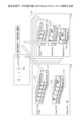
次に、図15~図17を参照して、ある時点の表示状態に復元するための処理について説明する。図15は、ユーザーが入力するオブジェクトの入力例と時系列編集モードの開始方法を説明する図である。図15(a)~(d)は、ユーザーによるオブジェクトの入力例を示す。図15(a)~(d)において、ユーザーは、手書きデータ151の入力、キャプチャ画像152の表示、スタンプ153の表示、手書きデータ154の入力を行っている。<Restoring the display state at a certain point in the past by operating the slider>
Next, processing for restoring the display state to a certain point in time will be described with reference to FIGS. 15 to 17. FIG. 15 is a diagram illustrating an example of an object input by the user and a method for starting the time series editing mode. FIGS. 15(a) to 15(d) show examples of object input by the user. In FIGS. 15A to 15D, the user is inputting
また、表示装置2は、複数のアプリケーションを同時に実行する機能を有している。本実施形態で説明する表示装置2の機能は1つのアプリケーション(以下、単にアプリという)で実現される。この他、表示装置2はWebブラウザ、遠隔会議アプリなども実行できる。複数のアプリが実行された場合、ディスプレイには他のアプリのウィンドウが表示される。 Furthermore, the
図16は、表示装置2のディスプレイ3に表示された他のアプリのウィンドウ160を示す。図16では、ディスプレイ3にオブジェクト161とウィンドウ160が表示されている。表示状態保存処理部18は、表示状態データに保存する情報に、他のアプリのウィンドウ160(画像データ)と表示位置(座標)を含めさせることができる。したがって、表示状態の復元時に、表示装置2は、他のアプリのウィンドウ160を復元できる。なお、表示状態保存処理部18は、他のアプリのウィンドウをOSから取得できる。 FIG. 16 shows a
図15に戻って説明する。ユーザーは、過去のある時点の表示状態に戻すため、図15(e)に示すように、時系列編集モードボタン150を押下した。表示装置2は図17に示すように時系列編集モードに移行する。なお、図17(a)(b)は図1とほぼ同じであるが説明のために再掲した。 The explanation will be returned to FIG. 15. In order to return to the display state at a certain point in the past, the user presses the time series
図17(a)は、時系列復元モードの画面例を示す。時系列復元モードでは、過去の異なる時点における表示状態のサムネイル101が直線上にスライド可能に表示される。サムネイル101は表示状態データ116のうちオブジェクトリスト111に基づいて復元された表示状態を縮小した画像である。ユーザーが指や電子ペン4でサムネイル101にタッチし、サムネイル101を左右にスライドさせると、スライド方向に応じて過去又は未来の表示状態のサムネイル101が表示される。ユーザーが指や電子ペン4でサムネイル101を押下すると、押下されたサムネイル101に対応する表示状態が選択される。 FIG. 17(a) shows an example of a screen in time series restoration mode. In the time-series restoration mode,
ユーザーが任意の表示状態を選択すると、図17(b)に示すように、表示装置2は選択された表示状態で表示されていたオブジェクトを表示する。このオブジェクトは、選択された表示状態に対応する表示状態データのオブジェクトリスト111を復元処理部16が取得して、画面に表示したものである。復元処理の詳細は図19、図20にて説明する。 When the user selects an arbitrary display state, the
復元された表示状態は画像データではなく、オブジェクトの状態で表示される。オブジェクトの状態とは、オブジェクトがストロークであれば、座標点列に基づいて表示されることをいう。図17(c)ではこれを利用して、ユーザーがオブジェクト163を指でスワイプすることで移動している。 The restored display state is displayed as an object, not as image data. The state of an object means that if the object is a stroke, it is displayed based on a coordinate point sequence. In FIG. 17C, the user uses this to move the
このように、ユーザーが表示状態データを選択して表示装置2が表示状態を復元した場合、画像データとしてでなく元のオブジェクトが表示されるので、ユーザーはオブジェクトの再編集(移動や消去など)や、一操作単位のUndo/Redoが可能である。 In this way, when the user selects the display state data and the
また、図10に示したように、表示状態データにUndoリスト112及びRedoリスト113が保存されているので、ユーザーは一操作単位ごとにUndo又はRedoすることもできる。つまり、ユーザーは、一定時間間隔単位又は一定回数操作単位で表示状態を復元した後、従来のUndo操作及びRedo操作で一操作毎にUndo又はRedoすることができる。 Furthermore, as shown in FIG. 10, since the display state data includes the Undo
また、図18に示すように、ユーザーはジェスチャー操作で表示状態を左右にスライドさせることもできる。図18は、ジェスチャー操作によるサムネイルの選択方法を説明する図である。ジェスチャー操作とは、ユーザーが画面にタッチさせる指の数に応じて操作内容を割り当てておき、タッチした指の数に応じた操作を表示装置2が受け付けることをいう。図18の説明では、3本指による操作は、時系列復元モードを実行する操作とする。なお、ジェスチャー操作の指の数は1本,2本又は4本以上でもよい。 Further, as shown in FIG. 18, the user can also slide the display state left and right by gesture operation. FIG. 18 is a diagram illustrating a method for selecting thumbnails by gesture operation. Gesture operation means that operation contents are assigned according to the number of fingers touched by the user on the screen, and the
したがって、ユーザーが3本の指で画面の任意の場所にタッチすると、表示装置2が時系列編集モードに移行する。表示装置2は、過去の異なる時点における表示状態のサムネイル101を直線上にスライド可能に表示する。ユーザーが3本の指でサムネイル101を左右にスライドさせると、スライド方向に応じて過去又は未来の表示状態に対応するサムネイル101が表示される。ユーザーが指や電子ペン4でサムネイル101を押下すると、押下されたサムネイル101に対応する表示状態が選択される。 Therefore, when the user touches any part of the screen with three fingers, the
このようにジェスチャー操作では、ユーザーが時系列復元モードを実行するために時系列編集モードボタン150を押下する必要がない。ユーザーが指や電子ペン4でサムネイル101を押下することで選択するのでなく、サムネイル101から指や電子ペン4を離した時に押下されていたサムネイル101が選択されてもよい。 In this manner, the gesture operation does not require the user to press the time series
なお、ユーザーが電子ペン4を使用している場合、ペン尻のタッチ、ペン先の長押し、又は、電子ペン4に設けられたボタンの押下により、表示装置2が時系列復元モードに移行することができる。 Note that when the user is using the
<表示状態の復元処理>
図19は、復元処理部16が、表示状態データを使用して、過去の表示状態を現在のページに復元する処理を説明する図である。図19は、現在のページ上で過去のある時点の表示状態を復元する例を示す。なお、表示装置2は、現在の表示状態115(オブジェクトリスト111、Undoリスト112及びRedoリスト113)をRAM203の決まったアドレス(メモリ領域)に保持している。<Display state restoration process>
FIG. 19 is a diagram illustrating a process in which the
ユーザーが時系列復元モードにおいてサムネイル101を左右にスライドさせ、復元する表示状態を選択する。これにより、復元処理部16は、表示状態リスト114における表示状態データを特定できる。 The user slides the
復元処理部16は、特定した表示状態データで現在、表示しているオブジェクトリスト111、Undoリスト112及びRedoリスト113を上書きする。すなわち、復元処理部16は、選択された表示状態データのオブジェクトリスト111で現在の表示状態のオブジェクトリスト111を上書きし、選択された表示状態のUndoリスト112で現在の表示状態のUndoリスト112を上書きし、選択された表示状態のRedoリスト113で現在の表示状態のRedoリスト113を上書きする。 The
こうすることで、任意のページの表示中に、復元処理部16が、過去の表示状態を復元できる。 By doing so, the
また、図20に示すように、復元処理部16は新規のページに過去のある時点の表示状態を復元できる。図20は、復元処理部16が、表示状態データを使用して、過去の表示状態を新規のページに復元する処理を説明する図である。ユーザーが時系列復元モードにおいて表示状態を左右にスライドさせ、復元する表示状態を選択する。これにより、復元処理部16は、表示状態リスト114における表示状態データ116を特定できる。 Further, as shown in FIG. 20, the
復元処理部16は、特定した表示状態データを新規のページの表示状態にコピーする。ページごとにRAM203に表示状態の領域を確保できる場合は、復元処理部16はページに対応するアドレスに表示状態データをコピーすればよい。現在のページ分の容量しかRAM203に確保できない場合、復元処理部16は現在のページに対応するアドレスに表示状態データをコピーすればよい(この場合は図19の処理と同等になる)。 The
新規のページに復元する場合、復元処理部16は、表示状態データのオブジェクトリスト111を新規のページの表示状態のオブジェクトリスト111にコピーし、選択された表示状態データのUndoリスト112を新規のページの表示状態のUndoリスト112にコピーし、選択された表示状態データのRedoリスト113を新規のページの表示状態のRedoリスト113にコピーする。 When restoring to a new page, the
こうすることで、復元処理部16が、新規のページに、過去の表示状態を復元できる。 By doing so, the
<過去のある時点の表示状態の復元とUndo/Redo機能の組み合わせ>
本実施形態の表示状態の復元方法は、従来のUndo/Redo操作よりも少ない操作回数で過去のある時点の表示状態を復元できるが、一操作単位で表示状態を復元することが困難である。しかし、ユーザーが、本実施形態の表示状態の復元方法を使用して、更にUndo/Redo機能を使用すれば一操作単位で表示状態を復元することができる。<Combination of restoration of display state at a certain point in the past and Undo/Redo function>
Although the display state restoration method of this embodiment can restore the display state at a certain point in the past with fewer operations than the conventional Undo/Redo operation, it is difficult to restore the display state in units of one operation. However, if the user uses the display state restoration method of this embodiment and also uses the Undo/Redo function, the display state can be restored in one operation.
図21は、過去のある時点の表示状態の復元とUndo/Redo機能の組み合わせを利用した一操作単位の表示状態の復元方法を説明する図である。図21(a)の現在の表示状態Aを「あいうえおかきくけ」という表示状態Bに戻したいとユーザーが考えている。 FIG. 21 is a diagram illustrating a method for restoring the display state of one operation unit using a combination of restoring the display state at a certain point in the past and the Undo/Redo function. The user wants to return the current display state A in FIG. 21(a) to the display state B of "Aiue Okakake".
まず、図21(b)に示すように、ユーザーは時系列復元モードにおいて表示状態のサムネイル101を左右にスライドさせ、表示状態Bに最も近い表示状態Cを選択する(必ずしも最も近い必要はない)。なお、表示装置2は、Undoボタン191とRedoボタン192を表示する。 First, as shown in FIG. 21(b), the user slides the
図21(c)に示すように、ユーザーが選択した表示状態Cは「あいうえおかきくけこ」である。表示状態Cは表示状態Bに対し「こ」が余分である。 As shown in FIG. 21(c), the display state C selected by the user is "AIUEOKAKIKUKEKO". Display state C has an extra "ko" than display state B.
そこで、ユーザーは図21(d)に示すように、Undo機能を使って「こ」が入力される前の表示状態に戻す。すなわち、「こ」のストロークデータの操作回数は2回分なので、ユーザーはUndoボタン191を2回押下する。 Therefore, the user uses the Undo function to return to the display state before "ko" was input, as shown in FIG. 21(d). That is, since the number of operations for the stroke data of "ko" is two times, the user presses the Undo
こうすることで、Undo機能のみで表示状態Aから表示状態Bに戻す場合よりも遙かに少ない操作回数でユーザーは表示状態Aから表示状態Bに戻すことができる。 By doing so, the user can return from display state A to display state B with a far fewer number of operations than when returning from display state A to display state B using only the Undo function.
図22は、図21とは異なるユーザーインターフェースにより、過去のある時点の表示状態の復元とUndo/Redo機能の組み合わせを利用した一操作単位の表示状態の復元方法を説明する図である。 FIG. 22 is a diagram illustrating a method for restoring the display state of one operation unit using a combination of restoring the display state at a certain point in the past and the Undo/Redo function using a user interface different from that in FIG. 21.
図22(a)の現在の表示状態Aを「あいうえおかきくけ」という表示状態Bに戻したいとユーザーが考えている。 The user wants to return the current display state A in FIG. 22(a) to the display state B of "Aiue Okakake".
まず、図22(b)(c)に示すように、ユーザーは時系列復元モードにおいてジェスチャー操作で表示状態のサムネイル101を左右にスライドさせ、表示状態Bに最も近い表示状態Cを選択する(必ずしも最も近い必要はない)。ユーザーは表示状態Cを指で押下する。 First, as shown in FIGS. 22(b) and 22(c), the user slides the display state thumbnail 101 to the left or right using a gesture operation in the time series restoration mode, and selects the display state C that is closest to the display state B (not necessarily (doesn't have to be the closest). The user presses display state C with his finger.
ユーザーが左右のスライド操作を止めると、図22(d)に示すように、ユーザーが選択した表示状態のサムネイル101の上下に、縦方向にサムネイル102(第二の表示状態の一例)が表示される。縦方向のサムネイル102は縦にスクロールする。縦方向のサムネイル102は、ユーザーが選択した表示状態を起点に、上方向に行くほど一操作ずつ前の表示状態を示し、下方向に行くほど一操作ずつ後の表示状態を示す。つまり、上方向の表示状態は横方向のスライドで選択された表示状態に対しN回Undo操作された場合の表示状態であり、下方向の表示状態は横方向のスライドで選択された表示状態に対しN回Redo操作された場合の表示状態である。N回は、選択したサムネイル101を起点とするサムネイル102の数である。 When the user stops the left/right slide operation, thumbnails 102 (an example of the second display state) are displayed vertically above and below the
図22(e)(f)に示すように、ユーザーが表示状態を縦にスクロールさせることで、一操作単位でUndo/Redoすることができる。 As shown in FIGS. 22(e) and 22(f), by vertically scrolling the display state, the user can Undo/Redo in one operation unit.
図22(g)に示すように、ユーザーがタッチパネルから指でサムネイル102を押下すると、復元処理部16はユーザーが押下したサムネイル102に対応する表示状態をディスプレイ3に復元する。このように、図22のようなユーザーインターフェースでは、ユーザーがスライド方向を変更することで、一操作単位の表示状態の復元が可能になる。ユーザーが指や電子ペン4でサムネイル102を押下することで選択するのでなく、サムネイル102から指や電子ペン4を離した時に押下されていたサムネイル102が選択されてもよい。 As shown in FIG. 22(g), when the user presses the
なお、図22では、左右のスライドで一定時間又は一定操作回数ごとの表示状態が表示され、上下のスライドで一操作単位の表示状態が表示されたが、左右、上下のスライド方向は逆でもよい。また、表示制御部15は、サムネイル101の上側にRedo操作に対応するサムネイル102を表示し、サムネイル101の下側にUndo操作に対応するサムネイル102を表示してもよい。 In addition, in FIG. 22, the left and right slides display the display state for each fixed time or fixed number of operations, and the upper and lower slides display the display state for each operation, but the left and right, up and down slide directions may be reversed. . Further, the
<復元処理の手順又は動作>
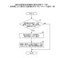
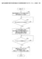
図23は、復元処理部16が表示状態を復元する処理を説明するフローチャート図である。図23では、図21にて説明したようにボタン操作により一操作単位で表示状態が復元される場合を説明する。<Procedure or operation of restoration process>
FIG. 23 is a flowchart illustrating the process by which the
まず、復元処理部16は、時系列編集モードボタン150の押下に応じて、表示状態データに基づいて表示状態をそれぞれ復元し、表示制御部15が表示状態のサムネイル101をスライド可能に表示する(S21)。ユーザーがディスプレイ3にタッチした指又は電子ペン4を左右に移動することでサムネイル101をスライドさせる。 First, the
復元処理部16は、操作受付部19が指又は電子ペン4によりサムネイル101の選択を受け付けたか否か判断する(S22)。 The
サムネイル101が選択された場合(S22のYes)、復元処理部16は、選択されたサムネイル101に対応する表示状態データで現在、表示しているオブジェクトリスト111、Undoリスト112及びRedoリスト113を上書きする(S23)。 If the
次に、操作受付部19は、Undoボタン又はRedoボタンが押下されたか否か判断する(S24)。 Next, the
Undoボタン又はRedoボタンが押下された場合(S24のYes)、復元処理部16は、ステップS23の表示状態データを起点に一操作分を元に戻す又は進める(S25)。 When the Undo button or the Redo button is pressed (Yes in S24), the
以上で、ユーザーは、過去のある時点の表示状態を復元し、一操作単位で表示状態を復元できる。 As described above, the user can restore the display state at a certain point in the past and restore the display state in one operation.
図24は、復元処理部16が表示状態を復元する処理を説明するフローチャート図である。図24では、図22にて説明したようにジェスチャー操作による左右と上下のスライド操作により表示状態が復元される場合を説明する。 FIG. 24 is a flowchart illustrating the process by which the
まず、復元処理部16は、ジェスチャー操作に応じて、表示状態データ116に基づいて表示状態をそれぞれ復元し、表示制御部15が表示状態のサムネイル101をスライド可能に表示する(S31)。 First, the
復元処理部16は、左右方向のスライド(ジェスチャー操作)が停止したか否かを判断する(S32)。 The
左右方向のスライドが停止した場合(S32のYes)、復元処理部16は、3本の指が離れた時のサムネイル101に対応する表示状態を起点に(中心に)、一操作分元に戻った及び一操作分進めた表示状態を縦方向に表示する(S33)。 When the slide in the left and right direction has stopped (Yes in S32), the
すなわち、復元処理部16は選択されたサムネイル101に対応する表示状態データが含むUndoリスト112の操作履歴に応じて一操作分戻した表示状態を操作履歴の数だけ復元する。表示制御部15は、復元された表示状態のサムネイル102を横方向のスライドで選択されたサムネイル101の上側に時系列に配置する。同様に、復元処理部16は選択された表示状態データが含むRedoリスト113の操作取消履歴に応じて一操作分進めた表示状態を操作取消履歴の数だけ作成する。表示制御部15は、復元された表示状態のサムネイル102を横方向のスライドで選択されたサムネイル101の下側に時系列に配置する。 That is, the
次に、復元処理部16は、操作受付部19が指又は電子ペン4によりサムネイル102の選択を受け付けたか否か判断する(S34)。 Next, the
サムネイル102が選択された場合(S34のYes)、復元処理部16は、選択されたサムネイル102に対応する表示状態データ(一操作分戻した又は進めた)で現在、表示しているオブジェクトリスト111、Undoリスト112及びRedoリスト113を上書きする(S35)。 When the
以上で、ユーザーは、過去のある時点の表示状態をジェスチャー操作で復元できる。 With the above, the user can restore the display state at a certain point in the past using gesture operations.
<サーバー・クライアントシステムへの適用>
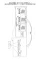
表示装置2の機能は、図25のような、サーバー・クライアントシステムの形態でも実現できる。図25は、表示システム310の概略構成図の一例である。インターネット等のネットワークを介して表示装置2とサーバー装置300とが接続されている。なお、サーバー装置300のハードウェアブロック図は、PCなどの汎用的な情報処理装置又はコンピュータと同様でよい。<Application to server/client systems>
The functions of the
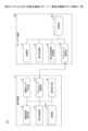
図26は、表示システム310における表示装置2とサーバー装置300の機能ブロック図を示す。表示システム310の場合、表示装置2は、図4に示した、接触位置検出部12、描画データ生成部13、表示制御部15、ネットワーク通信部17a、及び、操作受付部19を有する。表示装置2の記憶部20aには、現在のページの表示状態を示すオブジェクトリスト111、Undoリスト112及びRedoリスト113が保存されていればよい。表示装置2の記憶部20aのデータが、サーバー装置300の記憶部20bと同じ状態に同期されていてもよい。 FIG. 26 shows a functional block diagram of the
一方、サーバー装置300は、変換部14、復元処理部16、表示状態保存処理部18、及び、ネットワーク通信部17b(第二の通信部の一例)を有する。サーバー装置300の記憶部20bには、各ページのオブジェクトリスト111、Undoリスト112及びRedoリスト113、並びに、表示状態リスト114が保存される。 On the other hand, the
表示装置2のネットワーク通信部17a(第一の通信部の一例)はサーバー装置300に、オブジェクトリスト111に変更がある一操作ごとに操作内容を送信する。サーバー装置300は、図11,図12、図23、図24のフローチャート図と同様の処理を行い、表示状態データを保存し、復元処理を行う。 The
図27は、表示システム310が表示状態の保存と復元を行うシーケンス図の一例である。 FIG. 27 is an example of a sequence diagram in which the
S101:ユーザーは表示装置2に対し、オブジェクトの表示状態を変更する操作を行う。操作受付部19が操作を受け付ける。 S101: The user performs an operation on the
S102:表示装置2のネットワーク通信部17aはオブジェクトに関する一操作単位の操作内容をサーバー装置300に送信する。 S102: The
S103:サーバー装置300のネットワーク通信部17bが一操作単位の操作内容を受信し、表示状態保存処理部18が、図11又は図12の処理を行い、表示状態データを保存する。 S103: The
なお、ステップS101~S103は繰り返し実行される。 Note that steps S101 to S103 are repeatedly executed.
S104:次に、過去のある時点の表示状態を復元したいユーザーは、時系列編集モードへ移行する操作を行う。この操作は時系列編集モードボタン150の押下でもよいし、ジェスチャー操作でもよい。 S104: Next, the user who wants to restore the display state at a certain point in the past performs an operation to shift to the time series editing mode. This operation may be performed by pressing the time series
S105:表示装置2の操作受付部19は操作を受け付け、ネットワーク通信部17aは時系列編集モードへの移行要求をサーバー装置300に送信する。 S105: The
S106:サーバー装置300のネットワーク通信部17bが時系列編集モードへの移行要求を受信し、復元処理部16が、保存してある表示状態データ116に基づいて表示状態を復元する。 S106: The
S107:サーバー装置300のネットワーク通信部17bは、各表示状態のサムネイル101を表示装置2に送信する。表示装置2のネットワーク通信部17aは各表示状態のサムネイル101を受信し、表示制御部15が左右方向にスライド可能にサムネイル101を表示する。 S107: The
S108:ユーザーが任意のサムネイル101を選択する。 S108: The user selects an
S109:表示装置2の操作受付部19は選択を受け付け、ネットワーク通信部17aは表示状態データの識別情報(例えばページ番号)を指定して、復元要求をサーバー装置300に送信する。 S109: The
S110:サーバー装置300のネットワーク通信部17bが復元要求を受信し、ネットワーク通信部17bは、識別情報で特定される表示状態データを表示装置2に送信する。 S110: The
S111:表示装置2のネットワーク通信部17aは表示状態データを受信し、受信した表示状態データで現在、表示しているオブジェクトリスト111、Undoリスト112及びRedoリスト113を上書きする。 S111: The
このあとユーザーは、Undoボタン又はRedoボタンの押下により一操作単位のUndo/Redo操作を行うことができる。すでに表示装置2はUndoリスト112及びRedoリスト113を受信済みなので、表示制御部15がUndoボタン又はRedoボタンの押下に応じて、ステップS111で表示したオブジェクトの表示状態を一操作ずつ戻す又は進める。 Thereafter, the user can perform Undo/Redo operations for each operation by pressing the Undo button or the Redo button. Since the
図22のようなユーザーインターフェースを実現するには、ステップS107でサーバー装置300がサムネイル101と共にサムネイル102を送信する。表示装置2は図22のようなユーザーインターフェースを表示し、ユーザーが選択したサムネイル102に対応する表示状態データをサーバー装置300に要求する。あるいは、ステップS107でサーバー装置300がサムネイル101と共に各表示状態データを送信してもよい。表示装置2は表示状態データを使用して図22のようなユーザーインターフェースを表示し、ユーザーが選択したサムネイル102に対応する表示状態データを表示する。 To realize the user interface as shown in FIG. 22, the
このように、表示システム310によれば、表示装置2とサーバー装置300がインタラクティブにオブジェクトを表示できる。つまり、ユーザーは専用の表示装置2を使用しなくても、タッチパネルを有する汎用的な情報処理装置を使用して、専用の表示装置2と同等の機能を利用できる。 In this way, according to the
また、オブジェクトリスト111、Undoリスト112及びRedoリスト113、並びに、表示状態リスト114がサーバー装置300に保存されているので、遠隔地にある表示装置2やPCがサーバー装置300に接続して表示状態をリアルタイムに共有できる。 In addition, since the
<主な効果>
以上説明したように、本実施形態の表示装置2は、ある時点の表示状態に戻すために従来では操作回数に応じたUndo/Redoを必要とするのに対し、少ない操作回数(最小一操作)で復元できる。すなわち、表示装置2は、ユーザーの操作性を向上できる。<Main effects>
As explained above, the
<その他の適用例>
以上、本発明を実施するための最良の形態について実施例を用いて説明したが、本発明はこうした実施例に何等限定されるものではなく、本発明の要旨を逸脱しない範囲内において種々の変形及び置換を加えることができる。<Other application examples>
Although the best mode for carrying out the present invention has been described above using examples, the present invention is not limited to these examples in any way, and various modifications can be made without departing from the gist of the present invention. and substitutions can be added.
例えば、本実施形態では、ストロークデータの表示状態が保存される例を説明したが、オブジェクトはテキストでもよい。テキストの場合、一操作は一文字又は一度に変換された複数の文字単位である。 For example, in this embodiment, an example in which the display state of stroke data is saved has been described, but the object may be text. For text, an operation is a single character or multiple characters converted at once.
また、本実施形態では電子黒板を一例として説明したが、電子黒板は、電子ホワイトボード、電子情報ボード、などと呼ばれてよい。また、本実施形態は、タッチパネルを有する情報処理装置であれば好適に適用できる。タッチパネルを搭載した情報処理装置としては、例えば、PJ(Projector:プロジェクター)、デジタルサイネージ等の出力装置、HUD(Head Up Display)装置、産業機械、撮像装置、集音装置、医療機器、ネットワーク家電、ノートPC、携帯電話、スマートフォン、タブレット端末、ゲーム機、PDA(Personal Digital Assistant)、デジタルカメラ、ウェアラブルPC又はデスクトップPC等であってもよい。 Further, although the present embodiment has been described using an electronic blackboard as an example, the electronic blackboard may be called an electronic whiteboard, an electronic information board, or the like. Further, this embodiment can be suitably applied to any information processing device having a touch panel. Information processing devices equipped with touch panels include, for example, projectors (PJs), output devices such as digital signage, HUD (head up display) devices, industrial machinery, imaging devices, sound collection devices, medical equipment, network appliances, It may be a notebook PC, a mobile phone, a smartphone, a tablet terminal, a game console, a PDA (Personal Digital Assistant), a digital camera, a wearable PC, a desktop PC, or the like.
また、本実施形態ではペン先の座標をタッチパネルで検知する方法で電子ペン4の座標を検出したが、表示装置2はペン先の座標を超音波により検出してもよい。また、電子ペン4は発光と共に超音波を発信しており、表示装置2は超音波の到達時間により距離を算出する。表示装置2は、方向と距離により電子ペン4の位置を特定でき、電子ペン4の軌跡をストロークデータとしてプロジェクターが描画(投影)する。 Further, in this embodiment, the coordinates of the
また、図4などの構成例は、表示装置2による処理の理解を容易にするために、主な機能に応じて分割したものである。処理単位の分割の仕方や名称によって本願発明が制限されることはない。表示装置2の処理は、処理内容に応じて更に多くの処理単位に分割することもできる。また、1つの処理単位が更に多くの処理を含むように分割することもできる。 Further, in the configuration example shown in FIG. 4, etc., the
また、上記で説明した実施形態の各機能は、一又は複数の処理回路によって実現することが可能である。ここで、本明細書における「処理回路」とは、電子回路により実装されるプロセッサのようにソフトウェアによって各機能を実行するようプログラミングされたプロセッサや、上記で説明した各機能を実行するよう設計されたASIC(Application Specific Integrated Circuit)、DSP(digital signal processor)、FPGA(field programmable gate array)や従来の回路モジュール等のデバイスを含むものとする。 Moreover, each function of the embodiment described above can be realized by one or more processing circuits. Here, the term "processing circuit" as used herein refers to a processor programmed to execute each function by software, such as a processor implemented by an electronic circuit, or a processor designed to execute each function explained above. This includes devices such as ASICs (Application Specific Integrated Circuits), DSPs (digital signal processors), FPGAs (field programmable gate arrays), and conventional circuit modules.
本発明の実施形態は、コンピュータの能力および機能性に大きな改善をもたらす。これらの改善により、ユーザーは、情報処理装置において情報を格納し提示する方法であるテーブルとの、より効率的で堅牢な対話を提供するコンピュータを利用することができる。さらに、本発明の実施形態は、より効率的で強力かつ堅牢なユーザーインターフェースの使用を通じて、より良いユーザー体験を提供する。このようなユーザーインターフェースは、人間と機械との間のより良い相互作用を提供する。 Embodiments of the present invention provide significant improvements in computer power and functionality. These improvements enable users to utilize computers that provide more efficient and robust interaction with tables, the way information is stored and presented in information processing devices. Additionally, embodiments of the present invention provide a better user experience through the use of a more efficient, powerful, and robust user interface. Such user interfaces provide better interaction between humans and machines.
<請求項に関する付記>
[請求項1]
オブジェクトを表示する表示装置であって、
表示されている前記オブジェクトの表示状態データを条件が満たされるごとに保存する表示状態保存処理部と、
前記表示状態データの選択を受け付ける操作受付部と、
前記操作受付部が選択を受け付けた前記表示状態データに基づいて前記オブジェクトの表示状態を復元する復元処理部と、
を有することを特徴とする表示装置。
[請求項2]
前記表示状態保存処理部は、前記表示状態データを保存した後、前記条件が満たされ、かつ、表示されているオブジェクトの表示状態に変更があった場合にのみ、前記表示状態データを保存することを特徴とする請求項1に記載の表示装置。
[請求項3]
前記表示状態保存処理部は、前記条件が満たされるごとに、前記表示状態データを保存する時点における過去の操作履歴の線形リストを、前記表示状態データに対応付けて保存することを特徴とする請求項1に記載の表示装置。
[請求項4]
前記表示状態保存処理部は、前記表示状態データを保存した後に表示されているオブジェクトの表示状態を変更させた操作取消履歴の線形リストを、最後に保存された前記表示状態データに対応付けて保存することを特徴とする請求項3に記載の表示装置。
[請求項5]
前記復元処理部が復元した前記オブジェクトの表示状態を表す複数の画像を直線上に表示する表示制御部を有し、
前記表示制御部は、入力手段がタッチパネルに対し操作した方向に前記複数の画像をスライドさせ、
前記復元処理部は、前記入力手段が選択を受け付けた前記画像に対応する前記オブジェクトの表示状態をディスプレイに復元することを特徴とする請求項4に記載の表示装置。
[請求項6]
前記復元処理部は、復元した前記オブジェクトの表示状態を、Undo操作を受け付けた回数だけ、前記過去の操作履歴に応じて戻し、
前記復元処理部は、復元した前記オブジェクトの表示状態を、Redo操作を受け付けた回数だけ、前記操作取消履歴に応じて進めることを特徴とする請求項5に記載の表示装置。
[請求項7]
前記復元処理部が復元した前記オブジェクトの表示状態を表す複数の画像を直線上に表示する表示制御部を有し、
前記表示制御部は、入力手段がタッチパネルに対し操作した方向に前記複数の画像をスライドさせ、
前記入力手段が停止した場合、前記表示制御部は、前記入力手段がタッチしている前記画像の上方に、該画像に対応する前記表示状態を起点に前記過去の操作履歴に応じて戻した第二の表示状態の画像を表示し、
前記入力手段がタッチしている前記画像の下方に、該画像に対応する前記表示状態を起点に前記操作取消履歴に応じて進めた第二の表示状態の画像を表示することを特徴とする請求項4に記載の表示装置。
[請求項8]
前記条件は一定時間が経過するごとであり、前記一定時間を受け付けることを特徴とする請求項1~7のいずれか1項に記載の表示装置。
[請求項9]
前記条件は一定回数操作ごとであり、一定回数を受け付けることを特徴とする請求項1~7のいずれか1項に記載の表示装置。
[請求項10]
前記表示制御部は、前記復元処理部が復元した前記オブジェクトの表示状態を新規のページに表示することを特徴とする請求項5~7のいずれか1項に記載の表示装置。
[請求項11]
前記表示装置ではウィンドウを表示するアプリケーションが実行されており、
前記表示状態保存処理部は、前記アプリケーションのウィンドウの画面を前記表示状態データに含めることを特徴とする請求項1~10のいずれか1項に記載の表示装置。<Additional notes regarding claims>
[Claim 1]
A display device that displays an object,
a display state storage processing unit that stores display state data of the displayed object each time a condition is satisfied;
an operation reception unit that accepts selection of the display state data;
a restoration processing unit that restores the display state of the object based on the display state data whose selection has been accepted by the operation reception unit;
A display device comprising:
[Claim 2]
The display state storage processing unit may save the display state data only when the condition is satisfied and there is a change in the display state of the displayed object after the display state data is saved. The display device according to
[Claim 3]
The display state storage processing unit may store a linear list of past operation history at the time of saving the display state data in association with the display state data each time the condition is satisfied. The display device according to
[Claim 4]
The display state saving processing unit stores a linear list of operation cancellation history that changed the display state of the displayed object after the display state data was saved, in association with the display state data that was last saved. The display device according to
[Claim 5]
a display control unit that displays a plurality of images representing display states of the object restored by the restoration processing unit in a straight line;
The display control unit slides the plurality of images in a direction operated by the input means on the touch panel,
5. The display device according to
[Claim 6]
The restoration processing unit restores the display state of the restored object by the number of times an Undo operation is accepted according to the past operation history,
6. The display device according to
[Claim 7]
a display control unit that displays a plurality of images representing display states of the object restored by the restoration processing unit in a straight line;
The display control unit slides the plurality of images in a direction operated by the input means on the touch panel,
When the input means stops, the display control section displays a display state above the image that is being touched by the input means, the display state being returned to the previous state based on the past operation history, starting from the display state corresponding to the image. Display the image in the second display state,
A claim characterized in that below the image touched by the input means, an image in a second display state that is advanced from the display state corresponding to the image according to the operation cancellation history is displayed. The display device according to
[Claim 8]
The display device according to any one of
[Claim 9]
8. The display device according to
[Claim 10]
The display device according to
[Claim 11]
An application that displays a window is running on the display device, and
11. The display device according to
2 表示装置 2 Display device
Claims (14)
Translated fromJapanese表示されている前記オブジェクトの表示状態データを条件が満たされるごとに保存する表示状態保存処理部と、
前記表示状態データの選択を受け付ける操作受付部と、
前記操作受付部が選択を受け付けた前記表示状態データに基づいて前記オブジェクトの表示状態を復元する復元処理部と、
を有することを特徴とする表示装置。A display device that displays an object,
a display state storage processing unit that stores display state data of the displayed object each time a condition is satisfied;
an operation reception unit that accepts selection of the display state data;
a restoration processing unit that restores the display state of the object based on the display state data whose selection has been accepted by the operation reception unit;
A display device comprising:
前記表示制御部は、入力手段がタッチパネルに対し操作した方向に前記複数の画像をスライドさせ、
前記復元処理部は、前記入力手段が選択を受け付けた前記画像に対応する前記オブジェクトの表示状態をディスプレイに復元することを特徴とする請求項4に記載の表示装置。a display control unit that displays a plurality of images representing display states of the object restored by the restoration processing unit in a straight line;
The display control unit slides the plurality of images in a direction operated by the input means on the touch panel,
5. The display device according to claim 4, wherein the restoration processing unit restores, on the display, the display state of the object corresponding to the image whose selection has been accepted by the input means.
前記復元処理部は、復元した前記オブジェクトの表示状態を、Redo操作を受け付けた回数だけ、前記操作取消履歴に応じて進めることを特徴とする請求項5に記載の表示装置。The restoration processing unit restores the display state of the restored object by the number of times an Undo operation is accepted according to the past operation history,
6. The display device according to claim 5, wherein the restoration processing unit advances the display state of the restored object by the number of times a Redo operation is accepted in accordance with the operation cancellation history.
前記表示制御部は、入力手段がタッチパネルに対し操作した方向に前記複数の画像をスライドさせ、
前記入力手段が停止した場合、前記表示制御部は、前記入力手段がタッチしている前記画像の上方に、該画像に対応する前記表示状態を起点に前記過去の操作履歴に応じて戻した第二の表示状態の画像を表示し、
前記入力手段がタッチしている前記画像の下方に、該画像に対応する前記表示状態を起点に前記操作取消履歴に応じて進めた第二の表示状態の画像を表示することを特徴とする請求項4に記載の表示装置。a display control unit that displays a plurality of images representing display states of the object restored by the restoration processing unit in a straight line;
The display control unit slides the plurality of images in a direction operated by the input means on the touch panel,
When the input means stops, the display control section displays a display state above the image that is being touched by the input means, the display state being returned to the previous state based on the past operation history, starting from the display state corresponding to the image. Display the image in the second display state,
A claim characterized in that below the image touched by the input means, an image in a second display state that is advanced from the display state corresponding to the image according to the operation cancellation history is displayed. The display device according to item 4.
前記表示状態保存処理部は、前記アプリケーションのウィンドウの画面を前記表示状態データに含めることを特徴とする請求項1に記載の表示装置。An application that displays a window is running on the display device, and
2. The display device according to claim 1, wherein the display state storage processing unit includes a screen of a window of the application in the display state data.
表示されている前記オブジェクトの表示状態データを条件が満たされるごとに保存する表示状態保存処理部と、
前記表示状態データの選択を受け付ける操作受付部と、
前記操作受付部が選択を受け付けた前記表示状態データに基づいて前記オブジェクトの表示状態を復元する復元処理部、
として機能させるためのプログラム。A display device that displays objects,
a display state storage processing unit that stores display state data of the displayed object each time a condition is satisfied;
an operation reception unit that accepts selection of the display state data;
a restoration processing unit that restores the display state of the object based on the display state data whose selection has been accepted by the operation reception unit;
A program to function as
表示状態保存処理部が、表示されている前記オブジェクトの表示状態データを条件が満たされるごとに保存するステップと、
操作受付部が、前記表示状態データの選択を受け付けるステップと、
復元処理部が、前記操作受付部が選択を受け付けた前記表示状態データに基づいて前記オブジェクトの表示状態を復元するステップと、
を有することを特徴とする表示方法。A display method performed by a display device that displays an object, the display method comprising:
a display state storage processing unit storing display state data of the displayed object each time a condition is satisfied;
an operation reception unit accepting selection of the display state data;
a restoration processing unit restoring the display state of the object based on the display state data whose selection has been accepted by the operation reception unit;
A display method characterized by having the following.
前記表示装置は、
オブジェクトの表示状態を変更する操作を受け付ける操作受付部と、
前記オブジェクトに関する操作内容を前記サーバー装置に送信する第一の通信部と、を有し
前記サーバー装置は、
前記表示装置が表示している前記オブジェクトの表示状態データを条件が満たされるごとに保存する表示状態保存処理部と、
前記表示装置からの要求に応じて、前記表示状態データに基づいて前記オブジェクトの表示状態を復元する復元処理部と、
前記復元処理部が復元した前記オブジェクトの表示状態を表す複数の画像を前記表示装置に送信する第二の通信部と、を有し、
前記表示装置は、前記複数の画像を直線上に表示する表示制御部を有することを特徴とする表示システム。A display system in which a display device that displays an object and a server device communicate via a network,
The display device includes:
an operation reception unit that accepts an operation to change the display state of the object;
a first communication unit that transmits operation details regarding the object to the server device; the server device;
a display state storage processing unit that stores display state data of the object displayed by the display device each time a condition is satisfied;
a restoration processing unit that restores the display state of the object based on the display state data in response to a request from the display device;
a second communication unit that transmits a plurality of images representing display states of the object restored by the restoration processing unit to the display device;
A display system, wherein the display device includes a display control unit that displays the plurality of images in a straight line.
Priority Applications (2)
| Application Number | Priority Date | Filing Date | Title |
|---|---|---|---|
| JP2022068317AJP2023158459A (en) | 2022-04-18 | 2022-04-18 | Display device, program, display method, display system |
| US18/300,746US12159029B2 (en) | 2022-04-18 | 2023-04-14 | Display apparatus, display system, display method, and non-transitory recording medium |
Applications Claiming Priority (1)
| Application Number | Priority Date | Filing Date | Title |
|---|---|---|---|
| JP2022068317AJP2023158459A (en) | 2022-04-18 | 2022-04-18 | Display device, program, display method, display system |
Publications (1)
| Publication Number | Publication Date |
|---|---|
| JP2023158459Atrue JP2023158459A (en) | 2023-10-30 |
Family
ID=88307820
Family Applications (1)
| Application Number | Title | Priority Date | Filing Date |
|---|---|---|---|
| JP2022068317APendingJP2023158459A (en) | 2022-04-18 | 2022-04-18 | Display device, program, display method, display system |
Country Status (2)
| Country | Link |
|---|---|
| US (1) | US12159029B2 (en) |
| JP (1) | JP2023158459A (en) |
Family Cites Families (41)
| Publication number | Priority date | Publication date | Assignee | Title |
|---|---|---|---|---|
| KR20060028463A (en)* | 2006-03-09 | 2006-03-29 | 정성욱 | User fraud click tracking and prevention system in online advertising system and its method |
| US8203968B2 (en)* | 2007-12-19 | 2012-06-19 | Solarwinds Worldwide, Llc | Internet protocol service level agreement router auto-configuration |
| KR100977385B1 (en)* | 2008-04-10 | 2010-08-20 | 주식회사 팬택 | Mobile terminal capable of controlling a widget-type idle screen and a standby screen control method using the same |
| US20100306018A1 (en)* | 2009-05-27 | 2010-12-02 | Microsoft Corporation | Meeting State Recall |
| JP5013548B2 (en)* | 2009-07-16 | 2012-08-29 | ソニーモバイルコミュニケーションズ, エービー | Information terminal, information presentation method of information terminal, and information presentation program |
| JP5743047B2 (en)* | 2010-05-17 | 2015-07-01 | セイコーエプソン株式会社 | Display device and display method |
| US8484569B2 (en)* | 2010-06-30 | 2013-07-09 | International Business Machines Corporation | Saving and restoring collaborative applications in context |
| US9032331B2 (en)* | 2011-03-29 | 2015-05-12 | International Business Machines Corporation | Visual widget search |
| JP5406333B2 (en)* | 2012-05-29 | 2014-02-05 | 京セラ株式会社 | Portable terminal, control method and program |
| CN104428766B (en)* | 2012-07-03 | 2017-07-11 | 三菱电机株式会社 | Speech recognition equipment |
| KR102080741B1 (en)* | 2012-08-29 | 2020-02-24 | 엘지전자 주식회사 | Mobile terminal and control method thereof |
| JP5747883B2 (en) | 2012-09-13 | 2015-07-15 | コニカミノルタ株式会社 | Operation control method, operation control program, and operation control apparatus |
| US20140189516A1 (en)* | 2012-12-27 | 2014-07-03 | Huawei Technologies Co., Ltd. | Video preview display method and terminal device |
| US10282083B2 (en)* | 2013-06-09 | 2019-05-07 | Apple Inc. | Device, method, and graphical user interface for transitioning between user interfaces |
| CN104965641B (en)* | 2014-05-22 | 2018-12-28 | 腾讯科技(深圳)有限公司 | information display method and device |
| KR101728358B1 (en)* | 2014-08-25 | 2017-04-19 | 엘지전자 주식회사 | Mobile terminal and control method thereof |
| JP5905546B2 (en)* | 2014-08-28 | 2016-04-20 | 京セラ株式会社 | Electronics |
| JP2016110518A (en)* | 2014-12-09 | 2016-06-20 | キヤノン株式会社 | Information processing equipment, control method thereof, program, and storage medium |
| US9632664B2 (en)* | 2015-03-08 | 2017-04-25 | Apple Inc. | Devices, methods, and graphical user interfaces for manipulating user interface objects with visual and/or haptic feedback |
| KR20170013064A (en)* | 2015-07-27 | 2017-02-06 | 삼성전자주식회사 | Screen operating Method and electronic device supporting the same |
| JP2017058972A (en)* | 2015-09-16 | 2017-03-23 | レノボ・シンガポール・プライベート・リミテッド | Information processor, display method thereof, and program executable by computer |
| US10346510B2 (en)* | 2015-09-29 | 2019-07-09 | Apple Inc. | Device, method, and graphical user interface for providing handwriting support in document editing |
| US10491579B2 (en)* | 2016-06-03 | 2019-11-26 | Avaya Inc. | Independent parallel interaction space instantiation |
| US20180074775A1 (en)* | 2016-06-06 | 2018-03-15 | Quirklogic, Inc. | Method and system for restoring an action between multiple devices |
| KR102628789B1 (en)* | 2016-09-09 | 2024-01-25 | 삼성전자주식회사 | Electronic device and method for cotrolling of the electronic device |
| CN107272984A (en)* | 2017-05-19 | 2017-10-20 | 北京金山安全软件有限公司 | Application icon preview method and device and electronic equipment |
| JP6879098B2 (en)* | 2017-07-19 | 2021-06-02 | 京セラドキュメントソリューションズ株式会社 | Display device and display control program |
| JP6904142B2 (en) | 2017-07-28 | 2021-07-14 | 株式会社リコー | Communication system, communication method, electronic device |
| CN107479784B (en)* | 2017-07-31 | 2022-01-25 | 腾讯科技(深圳)有限公司 | Expression display method and device and computer readable storage medium |
| CN108255405B (en)* | 2018-01-19 | 2019-09-10 | Oppo广东移动通信有限公司 | User interface display method and device and terminal |
| JP2020108038A (en)* | 2018-12-27 | 2020-07-09 | キヤノン株式会社 | Control device, control method thereof, industrial automation system, program, and storage medium |
| CN109829070B (en)* | 2019-01-29 | 2021-01-08 | 维沃移动通信有限公司 | Image searching method and terminal equipment |
| US11868597B2 (en)* | 2019-03-14 | 2024-01-09 | Hytto Pte. Ltd. | Method and apparatus for controlling devices |
| US10795532B1 (en)* | 2019-03-14 | 2020-10-06 | International Business Machines Corporation | Interactive graphical user interface thumbnail |
| US11087561B2 (en)* | 2019-07-12 | 2021-08-10 | City University Of Hong Kong | Three-dimensional sketching in mobile augmented reality |
| JP2021022041A (en) | 2019-07-25 | 2021-02-18 | 株式会社リコー | Communication terminal, communication system, display control method, and program |
| CN110647274A (en)* | 2019-08-15 | 2020-01-03 | 华为技术有限公司 | Interface display method and equipment |
| JP7472638B2 (en) | 2020-05-11 | 2024-04-23 | 株式会社リコー | Information processing device, information processing system, information processing method, and program |
| US20230137492A1 (en)* | 2020-10-21 | 2023-05-04 | Beijing Zitiao Network Technology Co., Ltd. | Landscape interaction method and apparatus, electronic device, and storage medium |
| US11594257B2 (en)* | 2021-02-18 | 2023-02-28 | Microsoft Technology Licensing, Llc | Collaborative media object generation and presentation in improved collaborative workspace |
| JP2024517416A (en)* | 2021-04-19 | 2024-04-22 | アップル インコーポレイテッド | User Interface for Location Tracking |
- 2022
- 2022-04-18JPJP2022068317Apatent/JP2023158459A/enactivePending
- 2023
- 2023-04-14USUS18/300,746patent/US12159029B2/enactiveActive
Also Published As
| Publication number | Publication date |
|---|---|
| US20230333731A1 (en) | 2023-10-19 |
| US12159029B2 (en) | 2024-12-03 |
Similar Documents
| Publication | Publication Date | Title |
|---|---|---|
| JP7556214B2 (en) | Electronic whiteboard, audio playback method, program, and image processing system | |
| US9335860B2 (en) | Information processing apparatus and information processing system | |
| JP6493546B2 (en) | Electronic blackboard, storage medium, and information display method | |
| US20110216015A1 (en) | Apparatus and method for directing operation of a software application via a touch-sensitive surface divided into regions associated with respective functions | |
| US9454257B2 (en) | Electronic system | |
| US10855481B2 (en) | Live ink presence for real-time collaboration | |
| JP6089793B2 (en) | Associating handwritten information with documents based on document information | |
| WO2017138223A1 (en) | Image processing device, image processing system, and image processing method | |
| US10613732B2 (en) | Selecting content items in a user interface display | |
| KR200477008Y1 (en) | Smart phone with mouse module | |
| US20160117140A1 (en) | Electronic apparatus, processing method, and storage medium | |
| JP2024526466A (en) | Touch response method, device, smart interactive panel and storage medium | |
| CN202533924U (en) | Hand-written display screen and hand-written input pen | |
| CN108885556A (en) | control digital input | |
| JP5165661B2 (en) | Control device, control method, control program, and recording medium | |
| JP2023158459A (en) | Display device, program, display method, display system | |
| JP7467842B2 (en) | Display device, display method, and display program | |
| JP7279425B2 (en) | DISPLAY DEVICE, DISPLAY SYSTEM, OPERATING MODE CONTROL METHOD, AND PROGRAM | |
| CN102402360A (en) | Handwriting display screen, handwriting input pen and handwriting input method | |
| JP2022087633A (en) | Display device, erasing method switching method, program | |
| JP2024008833A (en) | Display device, operation method, program, display system | |
| US12164720B2 (en) | Display apparatus for receiving external image and detecting touch panel input and method for driving thereof | |
| JP7739733B2 (en) | Display device, display method, program, and display system | |
| JP7331578B2 (en) | Display device, image display method, program | |
| JP7383959B2 (en) | Display device, usage providing method, program, image processing system |
Legal Events
| Date | Code | Title | Description |
|---|---|---|---|
| A621 | Written request for application examination | Free format text:JAPANESE INTERMEDIATE CODE: A621 Effective date:20250218 |