JP2023156366A - System and method for controlling ultrasonic tools - Google Patents
System and method for controlling ultrasonic toolsDownload PDFInfo
- Publication number
- JP2023156366A JP2023156366AJP2023122381AJP2023122381AJP2023156366AJP 2023156366 AJP2023156366 AJP 2023156366AJP 2023122381 AJP2023122381 AJP 2023122381AJP 2023122381 AJP2023122381 AJP 2023122381AJP 2023156366 AJP2023156366 AJP 2023156366A
- Authority
- JP
- Japan
- Prior art keywords
- signal
- harmonic
- drive signal
- surgical tool
- cancellation
- Prior art date
- Legal status (The legal status is an assumption and is not a legal conclusion. Google has not performed a legal analysis and makes no representation as to the accuracy of the status listed.)
- Granted
Links
Images


Classifications
- A—HUMAN NECESSITIES
- A61—MEDICAL OR VETERINARY SCIENCE; HYGIENE
- A61B—DIAGNOSIS; SURGERY; IDENTIFICATION
- A61B17/00—Surgical instruments, devices or methods
- A61B17/32—Surgical cutting instruments
- A61B17/320068—Surgical cutting instruments using mechanical vibrations, e.g. ultrasonic
- A—HUMAN NECESSITIES
- A61—MEDICAL OR VETERINARY SCIENCE; HYGIENE
- A61B—DIAGNOSIS; SURGERY; IDENTIFICATION
- A61B17/00—Surgical instruments, devices or methods
- A61B2017/00017—Electrical control of surgical instruments
- A—HUMAN NECESSITIES
- A61—MEDICAL OR VETERINARY SCIENCE; HYGIENE
- A61B—DIAGNOSIS; SURGERY; IDENTIFICATION
- A61B17/00—Surgical instruments, devices or methods
- A61B2017/00017—Electrical control of surgical instruments
- A61B2017/00137—Details of operation mode
- A61B2017/00141—Details of operation mode continuous, e.g. wave
- A61B2017/00146—Details of operation mode continuous, e.g. wave with multiple frequencies
- A61B2017/0015—Details of operation mode continuous, e.g. wave with multiple frequencies applied simultaneously
- A—HUMAN NECESSITIES
- A61—MEDICAL OR VETERINARY SCIENCE; HYGIENE
- A61B—DIAGNOSIS; SURGERY; IDENTIFICATION
- A61B17/00—Surgical instruments, devices or methods
- A61B2017/00017—Electrical control of surgical instruments
- A61B2017/00137—Details of operation mode
- A61B2017/00154—Details of operation mode pulsed
Landscapes
- Health & Medical Sciences (AREA)
- Surgery (AREA)
- Engineering & Computer Science (AREA)
- Life Sciences & Earth Sciences (AREA)
- Heart & Thoracic Surgery (AREA)
- Nuclear Medicine, Radiotherapy & Molecular Imaging (AREA)
- Mechanical Engineering (AREA)
- Biomedical Technology (AREA)
- Dentistry (AREA)
- Medical Informatics (AREA)
- Molecular Biology (AREA)
- Animal Behavior & Ethology (AREA)
- General Health & Medical Sciences (AREA)
- Public Health (AREA)
- Veterinary Medicine (AREA)
- Surgical Instruments (AREA)
Abstract
Description
Translated fromJapanese [関連出願の相互参照]
本出願は、2015年7月15日出願の米国仮特許出願第62/192,838号の利
益を主張するものである。この米国仮特許出願の全開示内容は、引用することにより本明
細書の一部をなすものとする。[Cross reference to related applications]
This application claims the benefit of U.S. Provisional Patent Application No. 62/192,838, filed July 15, 2015. The entire disclosure of this U.S. provisional patent application is hereby incorporated by reference.
本発明は、概して、超音波式外科用ツールを制御するためのシステム及び方法に関し、
より具体的には、外科用ツールの動作により生じる望ましくない信号の存在を低減するた
めのシステム及び方法に関する。The present invention generally relates to systems and methods for controlling ultrasonic surgical tools;
More specifically, it relates to systems and methods for reducing the presence of undesirable signals caused by the operation of surgical tools.
超音波式吸引器等の超音波式外科用ツールは通常、超音波トランスデューサと、そのト
ランスデューサに接続され、組織に接する先端部とを有するハンドピースを備えている。
外科用ツールにはコンソール又は発電部(generator)が接続され、特定の駆動信号をト
ランスデューサに出力することにより外科用ツールが制御される。外科用ツールは、組織
を凝固させる等のために、開放術又は侵襲性が最小限の外科的手技において使用される。Ultrasonic surgical tools, such as ultrasonic aspirators, typically include a handpiece having an ultrasonic transducer and a tissue-contacting tip connected to the transducer.
A console or generator is connected to the surgical tool, and the surgical tool is controlled by outputting specific drive signals to the transducer. Surgical tools are used in open or minimally invasive surgical procedures, such as to coagulate tissue.
多くの先端部・トランスデューサの組み合わせにおいて、トランスデューサは、ある周
波数成分を有する正弦波駆動信号により駆動される。超音波式先端部は通常、単一の支配
的な振動モード(例えば、縦モード)のみを有する周波数成分において動作するように設
計される。In many tip-transducer combinations, the transducer is driven by a sinusoidal drive signal having certain frequency components. Ultrasonic tips are typically designed to operate in frequency components that have only a single dominant vibration mode (eg, a longitudinal mode).
先端部の振動運動は、業界において機械電流(mechanical current)と呼ばれるものに
直接的に関連する。機械電流がハンドピース電圧と同相であるときに、先端部は共振状態
において動作する。トランスデューサは、ある周波数成分を有する正弦波信号で駆動され
るので、ハンドピースへの電流は、結果として、ある周波数成分を有する正弦波である。The vibratory motion of the tip is directly related to what is referred to in the industry as mechanical current. The tip operates at resonance when the mechanical current is in phase with the handpiece voltage. Since the transducer is driven with a sinusoidal signal having certain frequency content, the current to the handpiece is consequently a sinusoidal wave having certain frequency content.
従来の超音波式先端部及びハンドピースの組み合わせによっては、必然的に、高調波歪
みを引き起こす高調波信号を示すものがある。そのような高調波信号により、ハンドピー
スへの電流が、ハンドピースへの電圧に対して可変の位相シフトを示す場合がある。従来
のシステムでは、ハンドピースへの電圧及び電流の両方において、相当の高調波歪みが存
在する。高調波信号により、ハンドピースへの電圧及び電流が、高調波等の付加的な周波
数成分を示し、それにより、電圧及び電流の波形が、乱れた正弦波になる。そのような高
調波は、先端部の望ましくない振動を引き起こす。望ましくない振動は、外科用ツールの
性能に悪影響を及ぼす。例えば、そのような望ましくない振動は、先端部にかかる応力を
高め、ある特定の場所において望ましくない過度の熱を生じさせる。そのような望ましく
ない過度の熱は、疲労及び周囲組織の加熱に起因して、先端部の寿命を縮める。さらに、
システムは、過度の熱から生じる温度上昇に起因して変化する先端部の音響特性の付加的
な負荷効果を克服するために、より高い電圧において動作しなければならない。それによ
り今度は、望ましくない振動エネルギーがハンドピースから制御コンソールに返されるた
め、コンソールの性能が低下する。Some conventional ultrasonic tip and handpiece combinations necessarily exhibit harmonic signals that cause harmonic distortion. Such harmonic signals may cause the current to the handpiece to exhibit a variable phase shift with respect to the voltage to the handpiece. In conventional systems, there is significant harmonic distortion in both the voltage and current to the handpiece. The harmonic signals cause the voltage and current to the handpiece to exhibit additional frequency components, such as harmonics, which cause the voltage and current waveforms to become distorted sinusoids. Such harmonics cause undesirable vibrations of the tip. Unwanted vibrations adversely affect the performance of surgical tools. For example, such undesirable vibrations can increase stress on the tip and create undesirable excessive heat at certain locations. Such undesirable excessive heat shortens the life of the tip due to fatigue and heating of the surrounding tissue. moreover,
The system must operate at higher voltages to overcome the additional loading effects of changing tip acoustic properties due to temperature increases resulting from excessive heat. This in turn causes unwanted vibrational energy to be returned from the handpiece to the control console, reducing console performance.
したがって、本発明によれば、超音波式外科用ツールを駆動することにより生じる高調
波信号の存在を低減するために、超音波式外科用ツールを制御するコンソールが提供され
る。本コンソールは、超音波式外科用ツールに第1駆動信号を印加するように構成される
。本コンソールは、超音波式外科用ツールに第1駆動信号を印加することにより生じる高
調波信号の特性を取得する。本コンソールは、高調波信号の特性に基づいて、キャンセル
信号を生成する。本コンソールは、第2駆動信号を生成するために第1駆動信号とキャン
セル信号とを合成する。第2駆動信号は正弦波である。第2駆動信号の印加により生じる
高調波信号の存在が、第1駆動信号の印加により生じる高調波信号の存在に比べて低減さ
れるように、本コンソールは、超音波式外科用ツールに第2駆動信号を印加するように構
成される。Accordingly, in accordance with the present invention, a console for controlling an ultrasonic surgical tool is provided to reduce the presence of harmonic signals caused by driving the ultrasonic surgical tool. The console is configured to apply a first drive signal to the ultrasonic surgical tool. The console obtains characteristics of the harmonic signal produced by applying the first drive signal to the ultrasonic surgical tool. The console generates a cancellation signal based on the characteristics of the harmonic signal. The console combines the first drive signal and the cancellation signal to generate a second drive signal. The second drive signal is a sine wave. The console connects the ultrasonic surgical tool to the second drive signal such that the presence of harmonic signals caused by the application of the second drive signal is reduced compared to the presence of harmonic signals caused by the application of the first drive signal. The drive signal is configured to apply a drive signal.
また、本発明によれば、超音波式外科用ツールを駆動することにより生じる高調波信号
の存在を低減するために、超音波式外科用ツールを制御する方法も提供される。本方法は
、超音波式外科用ツールを第1駆動信号により駆動するステップを含む。超音波式外科用
ツールを第1駆動信号により駆動するステップにより生じる高調波信号の特性が取得され
る。本方法は、高調波信号の特性に基づいて、キャンセル信号を生成するステップを含む
。第2駆動信号を生成するために第1駆動信号とキャンセル信号とが合成される。第2駆
動信号は正弦波である。本方法は、超音波式外科用ツールを第2駆動信号により駆動する
ことにより生じる高調波信号の存在が、超音波式外科用ツールを第1駆動信号により駆動
することにより生じる高調波信号の存在に比べて低減されるように、超音波式外科用ツー
ルを第2駆動信号で駆動するステップを含む。Also provided in accordance with the present invention is a method of controlling an ultrasonic surgical tool to reduce the presence of harmonic signals caused by driving the ultrasonic surgical tool. The method includes driving an ultrasonic surgical tool with a first drive signal. A characteristic of a harmonic signal resulting from driving the ultrasonic surgical tool with the first drive signal is obtained. The method includes generating a cancellation signal based on characteristics of the harmonic signal. The first drive signal and the cancellation signal are combined to generate a second drive signal. The second drive signal is a sine wave. The method includes determining whether the presence of a harmonic signal resulting from driving the ultrasonic surgical tool with the second drive signal is the presence of a harmonic signal resulting from driving the ultrasonic surgical tool with the first drive signal. driving the ultrasonic surgical tool with a second drive signal such that the ultrasonic surgical tool is reduced relative to .
さらに、本発明によれば、高調波信号の存在を低減するために、超音波式外科用ツール
を制御する方法が提供される。高調波信号は、周波数、位相及び振幅を含む。本方法は、
超音波式外科用ツールを第1駆動信号で駆動することと、超音波式外科用ツールを第1駆
動信号で駆動することから生じる高調波信号の特性を取得することと、高調波信号の周波
数と同様の周波数と、高調波信号の位相との関係で180度シフトされた位相と、高調波
信号以上の振幅とを有するキャンセル信号を生成することとを含む。本方法は、超音波式
外科用ツールを駆動するために第2駆動信号を出力することを更に含む。第2駆動信号は
、正弦波であり、第1駆動信号とキャンセル信号との合成に基づくものである。Additionally, in accordance with the present invention, a method is provided for controlling an ultrasonic surgical tool to reduce the presence of harmonic signals. A harmonic signal includes frequency, phase and amplitude. This method is
driving an ultrasonic surgical tool with a first drive signal; obtaining characteristics of a harmonic signal resulting from driving the ultrasonic surgical tool with a first drive signal; and determining a frequency of the harmonic signal. , a phase shifted by 180 degrees with respect to the phase of the harmonic signal, and an amplitude greater than or equal to the harmonic signal. The method further includes outputting a second drive signal to drive the ultrasonic surgical tool. The second drive signal is a sine wave and is based on the combination of the first drive signal and the cancellation signal.
本システム及び方法は、有利な点として、高調波信号の存在を低減し、それにより、外
科用ツールの振動から生じる高調波歪みを低減することができる。高調波信号の存在を低
減することにより、本システム及び方法は、外科用ツール、すなわち、ハンドピースと先
端部との組み合わせのインピーダンス、先端部の特有の振動変位を維持するために必要と
される電力及び電圧、先端部の加熱、コンソールに返されるエネルギー、及び/又は望ま
しくない(例えば、高調波)振動周波数を実効的に低減することができる。これらの変更
により、外科用ツールの組織切除性能を向上させることができる。The present systems and methods can advantageously reduce the presence of harmonic signals, thereby reducing harmonic distortion resulting from vibrations of surgical tools. By reducing the presence of harmonic signals, the present systems and methods reduce the impedance of the surgical tool, i.e., the handpiece and tip combination, required to maintain the characteristic vibrational displacement of the tip. Power and voltage, tip heating, energy returned to the console, and/or undesirable (eg, harmonic) vibration frequencies can be effectively reduced. These modifications can improve the tissue ablation performance of the surgical tool.
さらに、高調波信号の悪影響を低減することによって、本システム及び方法は、多くの
場合に高調波歪みを示す、種々のタイプ及び形状の超音波式ツール及び先端部を使用する
多用途性を高める。本システム及び方法は更に、切断性能を高めるために、先端部の2つ
の異なる共振モードを同時に制御(例えば2モード制御)できるようにする。Furthermore, by reducing the negative effects of harmonic signals, the present systems and methods increase the versatility of using various types and shapes of ultrasonic tools and tips that often exhibit harmonic distortion. . The systems and methods further enable simultaneous control of two different resonant modes of the tip (eg, bimodal control) to enhance cutting performance.
以下の説明を読んだ後に、本発明の理解が進むので、本発明の他の特徴及び利点が容易
に認識されるであろう。After reading the following description, other features and advantages of the invention will be readily appreciated as the invention becomes better understood.
I.システム概要
図を参照すると、幾つかの図を通して類似の数字が類似の又は対応する部分を示してお
り、超音波式外科用ツール20を駆動することから生じる高調波信号の存在を低減するた
めに、超音波式外科用ツール20を制御するためのシステム10及び方法12の態様が全
体を通して示される。I. System Overview Referring to the figures, like numbers indicate similar or corresponding parts throughout the several figures, to reduce the presence of harmonic signals resulting from driving the ultrasonic
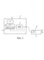
図1に示すように、システム10は、超音波式外科用ツール20と、超音波式外科用ツ
ール20を制御するためのコンソール22とを有する。外科用ツール20はコンソール2
2に接続される。外科用ツール20の例は、限定はされないが、医療用デバイスを含み、
限定はされないが、超音波式吸引器、超音波シーラー、超音波カッタ等を含む。As shown in FIG. 1,
Connected to 2. Examples of
Examples include, but are not limited to, ultrasonic aspirators, ultrasonic sealers, ultrasonic cutters, and the like.
外科用ツール20はハンドピース21を有する。図2に示すように、ハンドピース21
内にトランスデューサ24が収容される。トランスデューサ24は、電気エネルギーを機
械エネルギーに変換するのに適した、圧電セラミック要素等の任意の適切な要素又は構成
要素を備えたものとすることができる。外科用ツール20は、組織に関与するように構成
される遠位端を有する先端部26を更に有する。組織への関与の例として、組織の切断及
び/又は組織の封止が挙げられる。先端部26はトランスデューサ24に接続することが
できる。
A
外科用ツール20は様々な交換可能な先端部26を利用することができる。先端部26
は、ハンドピース21に永続的に又は着脱可能に固定することができる。先端部26は、
任意の適切な機能及び構成を有することができ、例えば、軟組織切除の先端部及び細骨切
断(fine bone dissection)の先端部を含むことができる。好ましい先端部26の例は、
限定はされないが、軟組織用のStryker(商標) Straight(商標)、S
tryker(商標) Barracuda(商標)、及び硬組織用のStryker(
商標) Claw(商標)、Stryker(商標) Knife(商標)、Stryk
er(商標) Payner(商標)を含む。
can be permanently or removably fixed to
It can have any suitable features and configurations, including, for example, a soft tissue dissection tip and a fine bone dissection tip. Examples of
Stryker(TM) Straight(TM), S for soft tissue, including but not limited to
tryker(TM) Barracuda(TM), and Stryker(TM) for hard tissue.
Trademarks) Claw (trademark), Stryker (trademark) Knife (trademark), Stryk
er (trademark) and Payner (trademark).
一実施形態において、コンソール22は、メモリ28と、コントローラ30と、増幅器
32とを有する。メモリ28は、外科用ツール20を制御するための関連するデータを記
憶するように構成される。メモリ28は、不揮発性メモリ、ROM、EEPROM、RA
M、フラッシュメモリ等の任意の適切なタイプのメモリとすることができる。コンソール
22は、外科用ツール20の制御を助けるために、メモリ28に記憶される任意の適切な
ファームウェア又はソフトウェアを有することができる。コントローラ30はメモリ28
に接続される。コントローラ30は、メモリ28に記憶された命令を実行するための1つ
以上のプロセッサを含むことができる。コントローラ30は、外科用ツール20に信号を
出力するための増幅器32と通信する。増幅器32は、一実施形態においては線形増幅器
である。In one embodiment,
M, may be any suitable type of memory, such as flash memory.
connected to.
コントローラ30は、サンプリングモジュール34、信号発生部36及び信号合成部3
8と通信することができる。図2において、サンプリングモジュール34、信号発生部3
6及び信号合成部38は、コントローラ30の一部であるか、又はコントローラ30と一
体に構成される。あるいは、サンプリングモジュール34、信号発生部36及び信号合成
部38のいずれか1つ又はその組み合わせを、コントローラ30から物理的に独立してい
るものとなるように、コントローラ30の物理的に外部に設けることができる。さらに、
場合によっては、サンプリングモジュール34、信号発生部36及び信号合成部38のい
ずれかを、同じ構成要素により一体に構成されるか、又は同じソフトウェアによって実施
されるように組み合わせることができる。サンプリングモジュール34は、高速フーリエ
変換(FFT)モジュール37と通信することができ、高速フーリエ変換(FFT)モジ
ュール37を含むものとすることができる。The
8 can be communicated with. In FIG. 2, a
6 and the
In some cases, any of the
サンプリングモジュール34、信号発生部36、FFTモジュール37及び信号合成部
38のいずれも、実行可能な命令を含むことができる。この実行可能な命令は、1つ以上
のプロセッサにより実行されるためにコンソール22のメモリ28に記憶される。サンプ
リングモジュール34、信号発生部36、FFTモジュール37及び信号合成部38の機
能は以下に詳細に説明する。The
II.第1の駆動信号及び高調波信号
コンソール22は、超音波式外科用ツール20に対して、より具体的にはトランスデュ
ーサ24に対して第1の駆動信号40を印加するように構成される。トランスデューサ2
4は、第1の駆動信号40の電気エネルギーを機械エネルギーに変換する。第1の駆動信
号40は、第1の駆動信号40を増幅させる、コンソール22内の増幅器32から出力さ
れる。第1の駆動信号40は低電圧である。例えば、第1の駆動信号40の電圧は0VA
C~100VACであり、より具体的には、0VAC~10VACであり、更に具体的に
は、0VAC~5VACである。増幅器32は、所望の機械電流を維持するために、必要
に応じて、第1の駆動信号40の電圧を1000VACまで増幅させる。外科用ツール2
0のコンソール22は、操作者が第1の駆動信号40を選択的に制御できるようにする任
意の適切なスイッチ又はボタンを含むものとすることができる。II. First Drive Signal and
4 converts the electrical energy of the
C to 100 VAC, more specifically, 0 VAC to 10 VAC, and even more specifically, 0 VAC to 5 VAC.
0
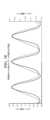
図3に、1つの特定のハンドピース21に対する第1駆動信号40の一例を示す。この
ハンドピース21は、鋭角ジョイント部(sharp angle joint)と、微小ストレート先端
部(micro straight tip)26とを有する。微小ストレート先端部26は、80mAの機
械電流において空中(in air)で25.5kHzの電圧正弦波駆動信号で駆動される。具
体的には、図3は第1の駆動信号40の電圧出力である。第1の駆動信号40は正弦波形
を有する。言い換えると、第1の駆動信号40は、滑らかな繰返しの振動を示す波形を有
する。したがって、第1の駆動信号40はパルス波又は矩形波ではない。第1の駆動信号
40の波形の正弦性は、先端部26内に超音波振動を与えるのに重要である。第1の駆動
信号40の正弦波形は、第1の駆動信号40の波長λ1に関連する周波数成分を含む。そ
の周波数成分は、基本(第1高調波)駆動周波数41の成分である。基本駆動周波数41
の成分は、所望の共振周波数としても知られている場合がある。この例において、基本駆
動周波数41の成分は25.5kHzである。基本駆動周波数41の成分は、例えば、2
5kHz~55kHzの範囲内の周波数を含む、任意の適切な周波数とすることができる
ことは、当業者は認識されよう。第1の駆動信号40は、位相「P1」及び振幅「a1」
を更に有する。コンソール22は、信号発生部36を用いて、第1の駆動信号40を生成
するように構成される。An example of the
The component of may also be known as the desired resonant frequency. In this example, the
Those skilled in the art will recognize that it can be any suitable frequency, including frequencies within the range of 5 kHz to 55 kHz. The
It further has.
第1の駆動信号40は、幾つかの特性を含む。第1の駆動信号40の特性は一般に、第
1の駆動信号40の波形に関連する。第1の駆動信号40の任意の特性は、時間領域又は
周波数領域に基づく特性とすることができる。例えば、図3に示すような時間領域に関し
て、第1の駆動信号40の特性は、波長λ1、位相「P1」及び振幅「a1」のうちの少
なくとも1つを含むことができる。図6及び図7に示すような、以下に示す周波数領域に
関して、例えば、第1の駆動信号40の特性は、第1の駆動信号40の周波数、大きさ及
び位相のうちの少なくとも1つを含むことができる。例えば、周波数は基本駆動周波数4
1の成分である。第1の駆動信号40の特性は、あらかじめ決定される場合があるか、又
は既知である場合がある。あるいは、第1の駆動信号40の特性を測定する場合がある。
例えば、第1の駆動信号40の特性は、以下に説明するように、第1の駆動信号40を印
加することに関連する電流又は電圧の測定値から導き出すことができる。第1の駆動信号
40の任意の特性を、時間領域のパラメータ及び周波数領域のパラメータから個別に、又
は組み合わせて導出できることは当業者には認識されよう。First drive
1 component. The characteristics of the
For example, the characteristics of the
図4に、ハンドピース21及び先端部26の組み合わせの電気機械回路モデルの一例を
示す。図4において、VSは、コンソール22からの出力駆動電圧(電圧源)である。以
下において、出力駆動電圧をハンドピース電圧VHPとも呼ぶ。図4において、RSはコ
ンソールの直列抵抗である。RSに流れる電流は、供給元電流iSであり、以下において
ハンドピース電流iHPとも呼ぶ。ハンドピース電流iHPは、ハンドピース21のイン
ピーダンスによって決定することができる。このインピーダンスは、ハンドピース21の
1つ以上の特徴から導き出すことができる。例えば、インピーダンスは、先端部26の負
荷、ハンドピース21の音響特性、切除される組織の音響特性、トランスデューサ24の
特性、ハンドピース21の振動等に起因する。FIG. 4 shows an example of an electromechanical circuit model of the combination of the
図4に示すように、静的なハンドピースのキャパシタンスはCoであり、静的なキャパ
シタンスCoに流れる電流はicoである。振動共振モードは、直列のRm、Lm及びC
mによって表される。ただし、imは所望の機械電流を表す。所望の機械電流imは、ハ
ンドピース21にかかる負荷によって誘発される。先端部26の振動運動は、所望の機械
電流imに直接的に関連する。先端部26の振動による変位は、機械電流imが増加する
につれて増加する。先端部26は、所望の機械電流imがハンドピース電圧VHPと同相
であるときに共振状態において作動する。As shown in FIG. 4, the capacitance of the static handpiece is Co and the current flowing through the static capacitance Co is ico . The vibrational resonance mode consists of Rm , Lm and C in series.
Represented bym . However, im represents the desired mechanical current. The desired mechanical current im is induced by the load on the
図4のモデルは、標準的なバターワース・バンダイク(Butterworth-VanDyke)モデル
に基づくが、一般的な構成要素Xとモデルに及ぼすその影響とを取り込むことによって改
善される。一般的な構成要素Xは、外科用ツール20、より具体的には、ハンドピース2
1及び先端部26の組み合わせに第1駆動信号40を印加することによる高調波信号44
を生じさせる理論的な構成要素である。高調波信号44は、基本駆動周波数41の成分の
2次高調波、3次高調波若しくは4次高調波等の、より高次の任意の高調波、又はその任
意の組み合わせを含むことができる。高調波信号44は、高調波歪みの原因であるため、
一般に望ましくない信号である。以下において、高調波信号44の周波数は、高調波周波
数43の成分と呼ぶ。高調波信号44は、必然的に、ハンドピース21及び先端部26の
特定の組み合わせに基づいて生じている場合がある。場合によっては、高調波信号44は
、先端部26の最小閾値の変位がなされるまで現れない。このような挙動は、非線形挙動
と見なされる。一般的な構成要素Xに流れる電流ixは、望ましくない機械電流を表す。
モデルの幾つかのバージョンにおいて、一般の構成要素Xは、所望の機械電流imによっ
て決まるか、又は所望の機械電流imに関連する振動電流源とすることができる。The model of FIG. 4 is based on the standard Butterworth-VanDyke model, but is improved by incorporating a common component, X, and its influence on the model. The general component X is a
1 and the
It is a theoretical component that gives rise to The
Generally an undesirable signal. In the following, the frequency of the
In some versions of the model,the general component X can be an oscillating current source determined by or related to the desired mechanical current i m.
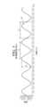
図5に、本明細書において説明される高調波キャンセル方法12を適用する前の、ハン
ドピース電流iHP及びハンドピース電圧VHPの波形と、ハンドピース電流iHP及び
ハンドピース電圧VHPの波形に及ぼす高調波信号44の例示的な影響とを示す。第1の
駆動信号40は正弦波であり、ある信号周波数成分を有するので、ハンドピース電流iH
P及びハンドピース電圧VHPは、結果として正弦波であり、ある信号周波数成分を有す
る。この場合、基本駆動周波数41の成分は、高調波周波数43の成分を伴うため、ハン
ドピース電流iHPの波形は、ハンドピース電圧VHPに対して可変の位相シフトφを示
す。ハンドピース電流iHP及びハンドピース電圧VHPは、複数の周波数成分を示すの
で、その波形は純粋な正弦波ではない。ハンドピース電流iHP及びハンドピース電圧V
HPは、とりわけ、利用される具体的な先端部26に応じて異なる。FIG. 5 shows the waveforms of handpiece current i HP and handpiece voltage VHP and the waveforms of handpiece current iHP and handpiece voltage VHP before applying the
P and the handpiece voltageVHP are sinusoidal as a result and have certain signal frequency components. In this case, the component of the
HP will vary depending on, among other things, the
図6及び図7に、図5のハンドピース電圧VHP及びハンドピース電流iHPの波形ご
とのそれぞれの高速フーリエ解析を示す。この解析は、図5に示したように、観測された
歪みの最も大きな原因となる一つの周波数(又は複数の周波数)を特定するものである。
この例において、FFT解析により、基本駆動周波数41の成分(すなわち25.5kH
z)が、高調波信号44の付加的な高調波周波数43の成分(例えば、51kHz)を伴
うことが明らかである。高調波信号44は、結果として生じる高調波歪みの原因である。
ハンドピース電圧VHPの場合、高調波周波数43の成分は、基本駆動周波数41の成分
の大きさの40%を超える大きさを示す。ハンドピース電流iHPの場合、高調波周波数
43の成分は、基本駆動周波数41の成分の大きさの90%を超える大きさを有する。図
6及び図7は、高調波周波数43の成分の一例を示すものであることを理解されたい。し
たがって、高調波周波数43の成分は、図6及び図7の高調波周波数とは異なる場合があ
り、異なる大きさを有する場合がある。6 and 7 show fast Fourier analysis of each waveform of handpiece voltage VHP and handpiece current iHP in FIG. 5, respectively. This analysis identifies one frequency (or a plurality of frequencies) that is the largest cause of the observed distortion, as shown in FIG.
In this example, the FFT analysis shows that the component of fundamental drive frequency 41 (i.e. 25.5kHz
z) is accompanied by an additional
For the handpiece voltage VHP , the
データを更に解析すると、ハンドピース電圧VHP及びハンドピース電流iHPの波形
における高調波信号44間の位相角θが103度であることが明らかになる。この位相角
θは90度より大きく、それは負の力率(power factor)を与え、(コンソールが51k
Hzにおいて電力を生成する代わりに)ハンドピース21及び先端部26の組み合わせが
51kHzにおいて電力を生成することを示す。この場合、25.5kHzの振動は、ハ
ンドピース21及び先端部26の組み合わせの非線形振動の挙動に起因して51kHzの
振動を誘発する。51kHzの振動は、トランスデューサ24内の圧電要素を動かし、そ
れにより、機械エネルギーのうちの一部を51kHzの電気エネルギー、すなわち、高調
波周波数43の成分に変換する。Further analysis of the data reveals that the phase angle θ between the
Hz), the
図8に、図4の回路の各分岐内の電流に対する、基本駆動周波数41の成分及び高調波
周波数43の成分のそれぞれの寄与を示す。この寄与は、Coのインピーダンスに対して
Rmの値が低いという仮定と、Rm、Lm、Cmの直列インピーダンスが高調波周波数4
3の成分において相対的に高いインピーダンスを有するという仮定とに基づく。図8にお
いて、基本駆動周波数41の成分及び高調波周波数43の成分はそれぞれ、ハンドピース
電流iHPに大きく寄与する。基本駆動周波数41の成分は、静的キャパシタンスCoに
流れる電流ico及び所望の機械電流imに大きく寄与する。これに対し、高調波周波数
43の成分は、静的キャパシタンスに流れる電流ico及び所望の機械電流imに実質的
に寄与しない。さらに、望ましくない機械電流ixに関して、基本駆動周波数41の成分
は実質的に寄与しないのに対し、高調波周波数43の成分は大きく寄与する。したがって
、このモデルによれば、ハンドピース電流iHP内に存在する高調波信号44は、一般の
構成要素Xに流れる望ましくない機械電流ixの存在に直接的に関係する。FIG. 8 shows the respective contributions of the
It is based on the assumption that there is a relatively high impedance in the three components. In FIG. 8, the
III.第2の駆動信号と高調波信号の低減
システム10及び方法12は、上述の高調波信号44の存在を低減するものである。図
9に示すように、方法12は、ステップ200において、超音波式ツール20に第1駆動
信号40を印加することを含むことができる。ステップ202において、超音波式外科用
ツール20に第1駆動信号40を印加することにより生じる高調波信号44の少なくとも
1つの特性が取得される。ステップ206において、取得された高調波信号44の特性に
基づいて、キャンセル信号70が生成される。ステップ208において、コンソール22
が、第1の駆動信号40とキャンセル信号70とを合成し、第2の駆動信号80を生成す
る。第2の駆動信号80は正弦波である。ステップ210において、コンソール22は、
第2駆動信号80を超音波式外科用ツール20に印加する。第2駆動信号50を印加する
ことにより生じる高調波信号44の存在は、第1駆動信号40を印加することにより生じ
る高調波信号44の存在に比べて低減される。この方法12の具体的なステップを以下に
詳細に説明する。III. Second Drive Signal and Harmonic
combines the
A
コンソール22は、ステップ202を実行して、高調波信号44の特性を取得する。高
調波信号44の特性は、時間領域又は周波数領域に基づく特性とすることができる。例え
ば、時間領域に関して、高調波信号44の特性は、波長λ2、位相「P2」及び振幅「a
2」のうちの少なくとも1つを含むことができる(図13を参照)。周波数領域に関して
、以下に説明する図6及び図7に示すように、例えば、高調波信号44の特性は、高調波
信号44の周波数、大きさ及び位相のうちの少なくとも1つを含むことができる。例えば
、高調波信号44の周波数は高調波周波数43の成分であり、より具体的には、第2の高
調波周波数(例えば51kHz)である。高調波信号44の任意の特性が、時間領域及び
周波数領域から個別に、又は組み合わせて取得できることは、当業者は認識されよう。
2 '' (see FIG. 13). Regarding the frequency domain, as shown in FIGS. 6 and 7 described below, for example, the characteristics of the
上記のように、第1の駆動信号40の特性はあらかじめ決定される場合があるか、又は
既知である場合がある。したがって、第1の駆動信号40の特性及び高調波信号44の特
性は、別の時点において決定することができる。あるいは、又はこれに加えて、第1の駆
動信号40の特性が未知である場合には、コンソール22はステップ202を実行して、
第1の駆動信号40の特性を更に取得することができる。言い換えると、第1の駆動信号
40の特性及び高調波信号44の特性は、同時に、又は別々の時点において決定すること
ができる。As mentioned above, the characteristics of the
Further characteristics of the
一実施形態において、コンソール22は、1つには、第1の駆動信号40の印加に関連
する電流及び電圧のサンプルを生成することによって、高調波信号44の特性を取得する
。より具体的には、電圧サンプルはハンドピース電圧VHPに基づき、電流サンプルはハ
ンドピース電流iHPに基づく。高調波信号44の特性は、高調波信号44の波形に関連
する。それゆえ、高調波信号44の特性は、電流及び電圧のサンプル内に存在し、そのサ
ンプルから抽出することができる。In one embodiment,
一例において、コンソール22は、測定するか、又は既知の静的キャパシタンス値Co
から開始することにより、高調波信号44の特性を取得する。第1の駆動信号40の基本
周波数41の成分のための電圧及び電流の両方の大きさ及び位相はあらかじめ決定される
か、又は既知であり、メモリ28からアクセスすることができる。この情報がわかると、
コンソール22は、ハンドピース21及び先端部26を、基本周波数41の成分(例えば
、25.5kHz)において相対的に低い振動レベルに設定されるような第1の駆動信号
40で駆動する。コンソール22は、共振を監視するトラッキングアルゴリズムを使用す
ることによって、基本周波数41の成分においてハンドピース21及び先端部26を駆動
し続けることができる。トラッキングアルゴリズムは、コントローラ30によって実行さ
れる。コントローラ30は、ハンドピース21及び先端部26が振動するのに応じて、そ
れらの共振を絶えず測定し、及び/又は計算する。トラッキングアルゴリズムは、測定さ
れた共振が所望の共振から外れる場合には、設計された共振を達成するために適切な調整
を行うように構成される。トラッキングアルゴリズムは、外科用ツール20の動作中に絶
えず実施することができる。任意の適切なトラッキングアルゴリズムを実施できることは
当業者には認識されよう。In one example, the
By starting from , the characteristics of the
コンソール22は、サンプリングモジュール34を用いて、第1の駆動信号40を印加
することにより生じる電流及び電圧のサンプルを取得する。コンソール22は、例えば、
上記の図5において示したような、ハンドピース電流iHP及びハンドピース電圧VHP
をサンプリングすることによって、電流及び電圧サンプルを取得する。あるいは、コンソ
ール22は、ハンドピース21及び先端部26のインピーダンスを監視し、及び/又はサ
ンプリングし、電流及び電圧サンプルを導き出すことができる。コンソール22は、アナ
ログ/デジタル変換デバイス等を用いて、更なる解析のために電流及び電圧サンプルを変
換する。コンソール22は、第1の駆動信号40及び/又は高調波信号44をサンプリン
グするか又はその特性を解析するために、図5に示したような波形を生成する必要がない
ことを当業者は理解されたい。代わりに、バイナリ値等の非視覚的データに基づいて、サ
ンプルを生成し、解析することができる。コンソール22は、外科用ツール20への第1
駆動信号40の印加中に、又は印加後にサンプルを取得することができる。取得されたサ
ンプルは、コントローラ30がサンプル取得後の任意の適切な時点においてサンプルにア
クセスすることができるように、メモリ28に記憶することができる。
Handpiece current iHP and handpiece voltage VHP as shown in FIG. 5 above.
Obtain current and voltage samples by sampling . Alternatively,
Samples can be taken during or after application of
コンソール22は、サンプルを解析して、高調波信号44の特性を取得する。高調波信
号44の特性を取得することによって、コンソール22は、ハンドピース電流iHP及び
ハンドピース電圧VHPの両方において(例えば、第2の高調波周波数43における)歪
みを測定することができる。一例において、コンソール22は、FFT解析技法を用いて
、高調波信号44の特性を取得する。ここで、コンソール22、より具体的には、FFT
モジュール37は、電流及び電圧サンプルのFFTを実行する。コンソール22は、任意
の駆動信号の印加中に電流及び電圧サンプルをリアルタイムに取得し、処理することがで
きる。
図10に、サンプリングされたハンドピース電流iHPのFFTの一例を示す。25.
5kHz及び51kHzの周波数成分は、スペクトルの他の部分に比べて振幅が大きいこ
とが示されている。コンソール22が、サンプルに基づいて、測定された歪みがかなり小
さいと判断した場合は、コンソール22は、許容できない高調波振動が生じるまで、機械
電流imを増加させ続けることができる。ここで、コンソール22は、高調波周波数43
の成分(第2の高調波)の振幅が基本駆動周波数41の成分すなわち25.5kHzの振
幅と概ね同程度になるまで、機械電流imを増加させる。FIG. 10 shows an example of the FFT of the sampled handpiece current iHP . 25.
The frequency components of 5 kHz and 51 kHz are shown to have large amplitudes compared to other parts of the spectrum. If the
The mechanical current im is increased until the amplitude of the component (second harmonic) becomes approximately the same as the amplitude of the component of the
高調波信号44の特性は、上記の図6及び図7に基づいて更に理解することができる。
これらの図に、説明された例においてFFTを実行した結果を表すグラフを示す。簡単に
するために、図6及び図7の内容は繰り返さない。FFTが変換を示すデータをもたらす
ことができ、それゆえ、高調波信号44の特性を取得するために、図6、図7及び図10
に示すようなグラフを生成する必要はないことを、当業者は理解されよう。したがって、
ある特定の実施形態において、電流及び電圧波形のFFTは、第2の駆動信号80を能動
的に生成するために実行され、それゆえ、FFTは診断のためだけに使用されるわけでは
ない。The characteristics of the
These figures show graphs representing the results of performing an FFT on the example described. For simplicity, the contents of FIGS. 6 and 7 are not repeated. 6, 7 and 10 to obtain the characteristics of the
Those skilled in the art will understand that it is not necessary to generate a graph such as that shown in FIG. therefore,
In certain embodiments, an FFT of the current and voltage waveforms is performed to actively generate the
高調波信号44の特性を判断するために、コンソール22は更に、第1の駆動信号40
の特性と高調波信号44の特性を比較することができる。一例において、コンソール22
は、第1の駆動信号40の位相P1と高調波信号44の位相P2との差を求める。あるい
は、コンソール22は、基本周波数41の成分におけるハンドピース電圧VHPの位相と
高調波周波数43の成分におけるハンドピース電流iHPの位相との差を求める。言い換
えると、コンソール22は、第1の高調波周波数におけるハンドピース電圧VHPに対す
る第2の高調波周波数におけるハンドピース電流iHPの位相を求める。第1の高調波周
波数におけるハンドピース電圧VHPに対する、第2の高調波周波数におけるハンドピー
ス電流iHPの位相は、位相角としても知られる。To determine the characteristics of the
The characteristics of the
calculates the difference between the phase P1 of the
これを行うために、コンソール22は、ハンドピース電圧VHP及びハンドピース電流
iHPの少なくとも一方に関して、高調波周波数43の成分から基本周波数41の成分を
分離する。例として、図11に、図5に示したハンドピース電流iHPに類似の、サンプ
リングされたハンドピース電流iHPを示す。サンプリングされたハンドピース電流iH
Pの波形は、2つの周波数成分、すなわち、基本周波数41の成分及び高調波周波数43
の成分を含む。To do this,
The waveform ofP has two frequency components, namely, a
Contains the following ingredients.
図12に、ハンドピース電圧VHPから抽出された基本周波数41の成分の波形を示す
。とりわけ、この例において、図12の波形は、図3の第1の駆動信号40の供給元波形
と同一である。すなわち、分離された基本周波数41の成分を含む波形は、第1駆動信号
40を印加することにより生じる高調波信号44がもたらされる前の第1駆動信号40の
供給元波形と同等である。FIG. 12 shows the waveform of the
図13に、図11のハンドピース電流iHPから抽出された高調波周波数43の成分を
分離した波形を示す。したがって、図3は、第1駆動信号40を印加することにより生じ
る、分離された高調波信号44を示すものである。図示されるように、高調波信号44は
、高調波信号44の波長λ2に関連する周波数成分を含む正弦波形を有する。また、高調
波信号44は、位相「P2」及び振幅「a2」をも有する。FIG. 13 shows a waveform in which the
一実施形態において、コンソール22は、位相角を計算することにより、基本周波数4
1の成分におけるハンドピース電圧VHPの位相と、高調波周波数43におけるハンドピ
ース電流iHPの位相との差を求める。この例では、ハンドピース電圧VHP及びハンド
ピース電流iHPの具体的な周波数、位相及び振幅を用いて、コンソール22は、以下の
式から位相角を計算する。
The difference between the phase of handpiece voltage VHP at
ここで、コンソール22は、ハンドピース電流iHPの高調波周波数44(51.5k
Hz)が、基本周波数41の成分(25.5kHz)におけるハンドピース電圧VHPに
対して-90度だけ位相がずれていると判断する。位相が-90度だけずれていると判断
すると、コンソール22は、キャンセル信号70を調整できるようになる。主に、高調波
信号44の振幅を数学的にキャンセルするために、キャンセル信号70の位相は、高調波
信号44の位相に対して180度シフトされる。キャンセル信号70は、第1駆動信号4
0に関連する。キャンセル信号70の電流は、必然的に、キャンセル信号70の電圧と同
相である。判明した高調波電流の波形は、第1駆動信号40から90度だけシフトされる
。キャンセル信号70により高調波信号44をキャンセルするために、キャンセル信号7
0は、第1駆動信号40に対して逆の方向に90(-90)度だけシフトされる。結果と
して、キャンセル信号70の位相は、高調波信号44の位相に対して180度シフトされ
る。Here, the
Hz) is out of phase by -90 degrees with respect to the handpiece voltage VHP at the
Related to 0. The current of the
0 is shifted by ninety (-90) degrees in the opposite direction relative to the
方法12は、ステップ206において、高調波信号44の特性に基づいて、コンソール
22においてキャンセル信号70を生成することを含む。キャンセル信号70は、高調波
信号44の存在を低減し、それにより、高調波信号44の影響を最小化するように構成さ
れる。一実施形態において、キャンセル信号70は、高調波信号44の存在を低減するこ
とに関して最も高い効果を有するものとなるように作られる。実際には、キャンセル信号
70は、望ましくない機械電流ixの1つ以上の特性に基づく。したがって、キャンセル
信号70は、望ましくない機械電流ix内の高調波信号44の存在を最小化する。言い換
えると、本明細書において説明される例において、キャンセル信号70は、第2の高調波
周波数43の成分における望ましくない機械電流ixを最小化し、それにより、ハンドピ
ース電流iHPの高調波歪みを最小化する。コンソール22は、信号発生部36を用いて
、キャンセル信号70を生成する。生成されたキャンセル信号70に関連するデータをメ
モリ28に記憶することができる。
図14に、キャンセル信号70の波形の一例を示す。図示されるように、キャンセル信
号70は、キャンセル信号70の波長λ3に関連する周波数成分を含む正弦波形を有する
。また、キャンセル信号70は、位相「P3」及び振幅「a3」をも有する。FIG. 14 shows an example of the waveform of the
一実施形態において、コンソール22は、高調波信号44の周波数に基づいて、キャン
セル信号70を生成する。例えば、キャンセル信号70の周波数は、高調波信号44を最
小化するように定めることができる。より具体的には、コンソール22は、キャンセル信
号70の周波数が高調波信号44の周波数に類似のものとなるようにキャンセル信号70
を生成する。その場合、図14のキャンセル信号70の波長λ3は、図13の高調波信号
44の波長λ2と同じである。より具体的には、この例において、キャンセル信号70の
周波数は、高調波信号44について求められた周波数である51kHzに設定される。高
調波信号44と同じ周波数を有することによって、キャンセル信号70は、基本周波数4
1の成分に影響を及ぼすことなく、又はそうでなくても他の望ましくない周波数をもたら
すことなく、高調波周波数43の成分の影響を低減するために、高調波周波数43の成分
を直接の対象とする。キャンセル信号70の周波数が、高調波周波数43の成分に厳密に
は等しくないが、類似である場合があることを、当業者は認識されよう。例えば、キャン
セル信号70の周波数は、高調波信号44の残存効果を考慮するために、高調波周波数4
3よりも数百ヘルツ大きいか、又は小さい場合がある。別の例において、キャンセル信号
70の周波数は、高調波周波数43より1kHz大きいか、又は小さい場合がある。In one embodiment,
generate. In that case, the wavelength λ3 of the
Directly target the component at
It may be several hundred hertz greater or less than 3. In another example, the frequency of
キャンセル信号70は更に、キャンセル信号70の位相P3が高調波信号44の位相P
2に対してシフトしたものとなるように作ることができる。一実施形態において、キャン
セル信号70の位相P3は高調波信号44を最小化するように定められる。一例において
、キャンセル信号70の位相P3は、高調波信号44の位相P2に対して180度シフト
される。したがって、図14のキャンセル信号70の位相P3は、図13の高調波信号4
4の位相P2に対して半周期シフトされる。位相P3を高調波信号44の位相P2に対し
て180度シフトさせることによって、キャンセル信号70の振幅a3が、図14に示す
ように高調波信号44の振幅a2の正反対となるため、キャンセル信号70による高調波
信号44のキャンセル効果が最大となる。キャンセル信号70の位相P3が高調波信号4
4の位相P2に対して180度以外の角度だけシフトされる場合があることを、当業者は
認識されよう。例えば、キャンセル信号70の位相P3は、540度、-180度等の、
180度の任意の正又は負の奇数倍だけシフトされる場合がある。The
It can be made to be shifted with respect to 2. In one embodiment, the phase P3 of
It is shifted by half a cycle with respect to the phase P2 of 4. By shifting the phase P3 by 180 degrees with respect to the phase P2 of the
Those skilled in the art will recognize that the phase P2 of 4 may be shifted by angles other than 180 degrees. For example, the phase P3 of the
It may be shifted by any positive or negative odd multiple of 180 degrees.
キャンセル信号70は、キャンセル信号70の振幅a3が高調波信号44の振幅a2に
対して調整されるように更に設計することができる。一実施形態では、図14に示すよう
に、キャンセル信号70の振幅a3は高調波信号44の振幅a2に等しい。キャンセル信
号70の振幅a3を高調波信号44の振幅a2に等しくすることによって、キャンセル信
号70による高調波信号44のキャンセル効果が最大となる。すなわち、キャンセル信号
70の振幅a3は、図14に示すように、高調波信号44の振幅a2に等しく、その逆で
ある(位相シフトに基づく)。The
あるいは、必要に応じて、キャンセル信号70は更に、キャンセル信号70の振幅a3
が高調波信号44の振幅a2よりも大きいか、又は小さいものとなるように設計すること
ができる。例えば、ある場合に、キャンセル信号70の振幅a3は、高調波信号44の振
幅a2の2倍である。本明細書において具体的には説明されない種々の他のレベルに従っ
て、キャンセル信号70の振幅a3を高調波信号44の振幅a2との関係で設定できる場
合があることが当業者には認識されよう。一実施形態において、キャンセル信号70の位
相a3は高調波信号44を最小化するように設計することができる。Alternatively, if necessary, the
can be designed to be larger or smaller than the amplitude a2 of the
他の実施形態では、キャンセル信号70の振幅a3は、高調波信号44に及ぼすキャン
セル信号70の振幅変化の影響を監視するように設計された振幅調整アルゴリズムに基づ
いて決定される。例えば、振幅調整アルゴリズムは、相対的に小さい振幅a3から始めて
、高調波周波数43の成分が最小化されるまで振幅a3を増加させることができる。コン
ソール22は、フィードバックループを用いて、高調波周波数43の成分への影響を監視
することができる。In other embodiments, the amplitude a3 of the
コンソール22が、高調波信号44の任意の特性のうちの少なくとも1つ、又はその組
み合わせに基づいて、キャンセル信号70を生成できることが当業者には認識されよう。
例えば、キャンセル信号70は、高調波信号44の周波数及び振幅a2に基づくが、高調
波信号44の位相P2に基づかずに生成される場合がある。あるいは、キャンセル信号7
0は、高調波信号44の周波数及び位相P2に基づくが、高調波信号44の振幅a2に基
づかずに生成される場合がある。そのような、キャンセル信号70を設計する際に高調波
信号44の幾つかの特性が考慮されない状況では、キャンセル信号70は、例えば、代わ
りの、又はデフォルトの周波数、位相又は振幅に基づいて生成することができる。Those skilled in the art will recognize that
For example, the
0 may be generated based on the frequency and phase P2 of the
ステップ208において、コンソール22は、第1駆動信号40とキャンセル信号70
とを合成して、第2駆動信号80を生成する。言い換えると、コンソール22は、キャン
セル信号70と、元の又は供給元の第1駆動信号40とを合成することにより、第2の駆
動信号80を生成する(結果的に高調波信号44が生じない)。コンソール22は、信号
合成部38を用いて、これら2つの信号を足し合わせる。コンソール22は、メモリ28
にある、第1駆動信号40及びキャンセル信号70についての情報にアクセスすることが
できる。At
The
Information about the
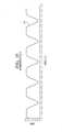
図15に、本明細書において説明される例の場合の第2駆動信号80の出力駆動電圧を
示す。第1駆動信号40と同様に、第2駆動信号80は、外科用ツール20の適切な超音
波動作を助けるために正弦波である。FIG. 15 shows the output drive voltage of the
キャンセル信号70は、ハンドピース電圧VHPと実効的に合成される。その場合、第
2駆動信号80の出力駆動電圧は、変更されたハンドピース電圧VHP’と理解すること
ができ、すなわち、第1駆動信号40の元のハンドピース電圧VHPとの関係で変わる場
合がある。図15の第2駆動信号80は、25.5kHzの第1駆動信号40(図12)
と、51kHzのキャンセル信号70(図14)との合成に基づく。その場合、第2駆動
信号80の電圧出力は、25.5kHzの駆動信号と51kHzのキャンセル信号との両
方を含む。言い換えると、キャンセル信号70は、主駆動電圧VHPの基本周波数41の
成分を確保するために第2の周波数成分77を与える。この第2の周波数成分77は、高
調波周波数43の成分に比べて180度位相がずれている位相シフトを有する第2の高調
波周波数43の成分にあり、それにより、高調波周波数43の成分を実効的に最小化する
。
and a 51 kHz cancellation signal 70 (FIG. 14). In that case, the voltage output of the
コンソール22、より具体的に信号合成部38は、数学的な演算を用いて、第1駆動信
号40とキャンセル信号70とを合成する。本明細書において説明される例の場合、信号
合成部38は、以下の式[2]を用いて信号を合成する。
より具体的には、第1駆動信号40及びキャンセル信号70のそれぞれの周波数、位相
及び振幅を入力すると、式[2]は、次のように表される。
ステップ210では、コンソール22が、第2駆動信号80を超音波式外科用ツール2
0に印加する。第1駆動信号40と同様に、コンソール22は、超音波式外科用ツール2
0に、より具体的にはトランスデューサ24に対して第2駆動信号40を印加する。すな
わち、増幅器32が第2駆動信号80の電圧を増幅し、トランスデューサ24が第2駆動
信号80の電気エネルギーを機械エネルギーに変換する。At
Apply to 0. Similar to the
0, and more specifically, a
キャンセル信号70を導入することによって、第2駆動信号80は、高調波信号44の
低減を示すように特に設計される。第2駆動信号80は、望ましくない振動運動に対抗す
る力が生まれるようにトランスデューサ24を駆動する。この対抗する力が望ましくない
振動を実効的にキャンセルする。実際に、第2駆動信号80を印加することにより生じる
高調波信号44の存在が、第1駆動信号40を印加することにより生じる高調波信号44
の存在に比べて低減される。より具体的には、第2駆動信号80を印加した後の望ましく
ない機械電流ix内の高調波信号44の存在が低減される。言い換えると、本明細書にお
いて説明される例において、第2の高調波周波数43の成分における望ましくない機械電
流ixは、第2駆動信号80を印加した後に最小化され、それにより、ハンドピース電流
iHP内の高調波歪みが最小化される。By introducing the
is reduced compared to the existence of More specifically, the presence of undesirable
幾つかの実施形態において、コンソール22は、外科用ツール20の動作中にキャンセ
ル信号70を繰り返し生成するように構成される。例えば、コンソール22は、「n」個
の駆動信号(第1、第2、第3の駆動信号等)を出力し、各「第nの」駆動信号を印加す
ることにより生じる高調波信号(存在する場合)の特性を取得することができる。コンソ
ール22は、先端部26の使用の間中、又は外科的手技の間中に、高調波歪みを追跡し、
「n個の」キャンセル信号を与えることができる。このような場合、各「第nの」駆動信
号、各「第nの」キャンセル信号及び結果として生じる各高調波信号は、互いに異なる場
合がある。幾つかの実施形態において、高調波信号44が適切なレベルにあるとコンソー
ル22が判断するまで、コンソール22は、このプロセスを継続する。例えば、高調波信
号44が所定の閾値未満である(例えば、高調波周波数43の成分の大きさが基本周波数
41の成分の大きさの5%未満である)とコンソール22が判断するまで、又は高調波信
号44が除去されるまで、コンソール22はこのプロセスを継続することができる。In some embodiments,
"n" cancellation signals can be provided. In such cases, each "nth" drive signal, each "nth" cancellation signal and each resulting harmonic signal may be different from each other. In some embodiments,
コンソール22は、キャンセル信号70又は各「第nの」キャンセル信号を生成するた
めに、任意の適切な方法を用いて、高調波信号44のレベルを測定し、追跡することがで
きる。一例において、コンソール22は、Coに関する既知の値を用いて、ハンドピース
電流iHP内の高調波周波数43の成分を計算する。0付近まで最小化されると、Coに
流れる電流iC0の高調波周波数43成分は、残存する望ましくない運動電流(motional
current)ixを表す。
current) ix .
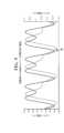
図15に、高調波キャンセル方法12を適用した後の、変更されたハンドピース電流i
HP’及びハンドピース電圧VHP’の波形を示す。図5の波形と比べて、図15の波形
に及ぼす高調波信号44の影響は大きく最小化されている。第2駆動信号80を印加した
後、基本駆動周波数41の成分は高調波周波数43の成分によって大きく影響を受けるこ
とはないので、ハンドピース電流iHP’の波形は、ハンドピース電圧VHP’に対して
最小の位相シフトφを示す。さらに、ハンドピース電流iHP’及びハンドピース電圧V
HP’は、主に1つの周波数成分、すなわち、基本駆動周波数41成分のみを示すので、
波形は実質的に正弦波である。FIG. 15 shows the modified handpiece current i after applying
The waveforms ofHP' and handpiece voltage VHP' are shown. Compared to the waveform of FIG. 5, the influence of
SinceHP' mainly indicates only one frequency component, that is, the
The waveform is substantially sinusoidal.
図16及び図17に、図15の変更されたハンドピース電圧VHP’及びハンドピース
電流iHP’の波形ごとのそれぞれの高速フーリエ解析を示す。図6及び図7に比べて、
FFT解析は、基本駆動周波数41の成分(すなわち、25.5kHz)が高調波信号4
4の高調波周波数43の成分(例えば、51kHz)から実質的に影響を受けないことを
明らかにしている。さらに、51kHzにおける高調波周波数43の成分の大きさが低減
されている。ハンドピース電圧VHP’の場合、高調波周波数43の成分の大きさは、第
1駆動信号40から生じる高調波周波数43の成分の大きさの25%である。ハンドピー
ス電流iHP’の場合、高調波周波数43の成分の大きさは実質的に除去される。16 and 17 show respective fast Fourier analyzes for each waveform of the modified handpiece voltage VHP' and handpiece current iHP' of FIG. 15. Compared to FIGS. 6 and 7,
The FFT analysis shows that the component of the fundamental drive frequency 41 (i.e., 25.5kHz) is the
It has been revealed that there is no substantial influence from the
さらに、機械電流imは、先端部26の機械的変位に関連するため、ハンドピース電流
iHP内の歪みを最小化することは、ハンドピース電圧VHP内の歪みを最小化すること
よりも優先することができる。したがって、ハンドピース電流iHPよりもハンドピース
電圧VHP内の歪みの方が大きいが、両方の波形が51kHz周波数において著しい改善
を示す。Furthermore, since the mechanical current im is related to the mechanical displacement of the
さらに、方法12を用いて高調波周波数43の成分を抑えることによって、先端部26
の非線形制御及び2モード制御を実施する機会が与えられる場合がある。本明細書におい
て与えられる例において、非線形挙動は、外科用ツール20が基本駆動周波数41の成分
、25.5kHzの電圧正弦波で駆動されるときに、ハンドピース21及び先端部26の
組み合わせが、高調波周波数43の成分、51kHzにおいて振動するような挙動である
。高調波周波数43の成分を抑えることによって、先端部26を動的に制御して、従来で
は到達するのが難しかった体内の領域に、外科医が近づきやすくすることができる。言い
換えると、高調波信号41の成分の悪影響を低減することによって、システム10及び方
法12は、多くの場合に高調波歪みを示す、種々のタイプ及び形状の超音波式ツール及び
先端部を使用する多用途性を高める。システム10及び方法12は更に、切断性能を高め
るために、先端部26の2つの異なる共振モードを同時に制御(例えば2モード制御)で
きるようにする。さらに、キャンセル信号70は高調波信号44を低減するが、キャンセ
ル信号70は、ツール20の2モード制御を達成するために、付加的な周波数成分を第2
駆動信号80の中にもたらすように構成することもできる。Furthermore, by suppressing the components of the
Opportunities may be provided to implement nonlinear control and bimodal control. In the example given herein, the nonlinear behavior is such that when the
It can also be configured to be provided in the
図19に、ハンドピース21及び先端部26の組み合わせを制御する数多くの重要なパ
ラメータの大きな改善を示す表を与える。例えば、第2駆動信号80の印加中に測定され
たハンドピース電圧VHP’及びハンドピース電流iHP’は、第1駆動信号40の印加
中に測定されたハンドピース電圧VHP及びハンドピース電流iHPに比べて、22%~
23%だけ低減されている。同様に、第2駆動信号80の印加中に測定されたハンドピー
ス21及び先端部26のインピーダンスは、第1駆動信号40の印加中に測定されたハン
ドピース21及び先端部26のインピーダンスに比べて23%だけ低減されている。重要
なこととして、第2駆動信号80の印加中に測定された51kHz成分におけるハンドピ
ース電流iHP’の相対的な大きさが、実質的に除去され、すなわち、第1駆動信号40
の印加中と比べて98.8%だけ低減されている。さらに、この例において、第2駆動信
号80の印加後に51kHzに存在する望ましくない機械電流ixは3.4mAであった
。これは、83mAであった、第1駆動信号40の印加後に51kHzに存在する望まし
くない機械電流ixよりも著しく小さく、それにより、望ましくない振動の著しい低減を
示す。FIG. 19 provides a table showing significant improvements in a number of important parameters controlling the
It has been reduced by 23%. Similarly, the impedance of the
This is reduced by 98.8% compared to when . Furthermore, in this example, the undesired mechanical current ix present at 51 kHz after application of the
これらの結果は、システム10及び方法12が高調波信号44の存在を実効的に低減し
、それにより、外科用ツール20の振動から生じる高調波歪みを低減することを明確に示
すものである。それにより、システム10及び方法12は、外科用ツール20のインピー
ダンス、先端部26の特有の振動変位を維持するために必要とされる電力及び電圧、先端
部26の加熱、コンソール22に返されるエネルギー、及び高調波周波数43の成分を明
確に低減している。それにより、更には、システム10及び方法12は、外科用ツール2
0の組織切除性能を大きく改善する。These results clearly demonstrate that
This greatly improves the tissue ablation performance of 0.
幾つかの実施形態が上記の説明で論じられた。しかし、本明細書で論じる実施形態は、
網羅的であることが意図されていないか、又は本発明が任意の特定の形態に限定されるこ
とが意図されていない。使用されている用語は、限定的ではなく、説明の言葉(words of
description)の性質内にあることを意図される。多くの変更及び変形が、上記教示を考
慮して可能であり、本発明は、具体的に述べられる以外の方法で実施することができる。Several embodiments have been discussed above. However, the embodiments discussed herein
It is not intended to be exhaustive or to limit the invention to any particular form. The terms used are descriptive, rather than restrictive.
description). Many modifications and variations are possible in light of the above teachings, and the invention may be practiced otherwise than as specifically described.
詳述された明細書から本発明の数多くの特徴及び利点が明らかであり、それゆえ、添付
の特許請求の範囲が、本発明の真の趣旨及び範囲に入る本発明の全てのそのような特徴及
び利点に及ぶことを意図している。さらに、当業者には数多くの変更及び変形が容易に思
い浮かぶことになるので、本発明を図示及び説明されたのと全く同じ構成及び動作に限定
することは望ましくなく、それゆえ、本発明の範囲内に入る、全ての適切な変更形態及び
均等物が採用される場合がある。Numerous features and advantages of the invention will be apparent from the detailed specification, and it is therefore intended that the appended claims cover all such features of the invention that fall within the true spirit and scope of the invention. and benefits. Furthermore, since numerous modifications and variations will readily occur to those skilled in the art, it is not desirable to limit the invention to the exact construction and operation shown and described, and therefore All suitable modifications and equivalents falling within the scope may be employed.
Claims (15)
Translated fromJapanese12)であって、
前記超音波式外科用ツール(20)を第1駆動信号(40)により駆動するステップと
、
前記超音波式外科用ツール(20)を前記第1駆動信号(40)により駆動するステッ
プにより生じる前記高調波信号(44)の特性を取得するステップと、
取得された前記高調波信号(44)の特性に基づいてキャンセル信号(70)を生成す
るステップと、
前記第1駆動信号(40)と前記キャンセル信号(70)とを合成し、正弦波である第
2駆動信号(80)を生成するステップと、
前記超音波式外科用ツール(20)を前記第2駆動信号(80)により駆動するステッ
プであって、前記超音波式外科用ツール(20)を前記第2駆動信号(80)により駆動
するステップにより生じる高調波信号(44)の存在が、前記超音波式外科用ツール(2
0)を前記第1駆動信号(40)により駆動するステップにより生じる高調波信号(44
)の存在に比べて低減される、ステップと
を含む方法。A method for controlling an ultrasonic surgical tool (20) and reducing the presence of harmonic signals (44)
12),
driving the ultrasonic surgical tool (20) with a first drive signal (40);
obtaining characteristics of the harmonic signal (44) resulting from driving the ultrasonic surgical tool (20) with the first drive signal (40);
generating a cancellation signal (70) based on the characteristics of the acquired harmonic signal (44);
combining the first drive signal (40) and the cancellation signal (70) to generate a second drive signal (80) that is a sine wave;
driving the ultrasonic surgical tool (20) with the second drive signal (80); driving the ultrasonic surgical tool (20) with the second drive signal (80); The presence of a harmonic signal (44) caused by said ultrasonic surgical tool (2
0) by the first drive signal (40), the harmonic signal (44
) is reduced compared to the existence of .
に関する電流及び電圧のサンプルを生成するステップとして定められ、前記高調波信号(
44)の特性は、生成された前記電流及び電圧のサンプル内に存在するものである、請求
項1に記載の方法(12)。The step of obtaining the characteristics of the harmonic signal (44) further includes determining the characteristics of the first drive signal (40).
defined as the step of generating current and voltage samples with respect to said harmonic signal (
4. The method (12) of claim 1, wherein the characteristic of 44) is present in the generated current and voltage samples.
圧のサンプルの高速フーリエ変換を解析し、前記高調波信号(44)の特性を求めるステ
ップとして定められ、前記特性は前記高調波信号の周波数、振幅及び位相の少なくともい
ずれかである、請求項2に記載の方法(12)。The step of obtaining a characteristic of said harmonic signal (44) is further defined as the step of analyzing a fast Fourier transform of said generated current and voltage samples to determine a characteristic of said harmonic signal (44); 3. The method (12) of claim 2, wherein the characteristic is the frequency, amplitude and/or phase of the harmonic signal.
圧のサンプルを用いて前記高調波信号(44)を監視し、前記高調波信号(44)の特性
が所定のレベルに達するまで前記超音波式外科用ツール(20)に対する機械電流を増加
させるステップとして定められる、請求項2又は3に記載の方法(12)。Obtaining the characteristics of the harmonic signal (44) further includes monitoring the harmonic signal (44) using the generated current and voltage samples to determine whether the characteristics of the harmonic signal (44) are predetermined. 4. A method (12) according to claim 2 or 3, defined as the step of increasing the mechanical current to the ultrasonic surgical tool (20) until reaching a level of .
波数と略同じ周波数と前記高調波信号(44)の位相との関係で180度シフトされた位
相とを有する前記キャンセル信号(70)を生成するステップとして定められる、請求項
1~4のいずれか一項に記載の方法(12)。The step of generating the cancellation signal (70) further includes the step of generating the cancellation signal (70) having a frequency substantially the same as the frequency of the harmonic signal (44) and a phase shifted by 180 degrees with respect to the phase of the harmonic signal (44). A method (12) according to any one of claims 1 to 4, defined as the step of generating a cancellation signal (70).
幅以上の振幅を有する前記キャンセル信号(70)を生成するステップとして定められる
、請求項1~5のいずれか一項に記載の方法(12)。Any one of claims 1 to 5, wherein the step of generating the cancellation signal (70) is further defined as the step of generating the cancellation signal (70) having an amplitude greater than or equal to the amplitude of the harmonic signal (44). The method described in Section (12).
幅の2倍である振幅を有する前記キャンセル信号(70)を生成するステップとして定め
られる、請求項6に記載の方法(12)。7. The step of generating the cancellation signal (70) is further defined as the step of generating the cancellation signal (70) having an amplitude that is twice the amplitude of the harmonic signal (44). Method (12).
調整し、前記キャンセル信号(70)の振幅の調整が前記高調波信号(44)にどのよう
な影響を及ぼすかを監視し、前記キャンセル信号(70)の振幅を、他の振幅に比べて前
記高調波信号(44)に対する最大のキャンセル効果を有する振幅として選択するステッ
プとして定められる、請求項6又は7に記載の方法(12)。The step of generating the cancellation signal further includes adjusting the amplitude of the cancellation signal (70) and monitoring how adjusting the amplitude of the cancellation signal (70) affects the harmonic signal (44). and selecting the amplitude of the cancellation signal (70) as the amplitude that has the greatest cancellation effect on the harmonic signal (44) compared to other amplitudes. (12).
プと、
前記超音波式外科用ツール(20)を前記第2駆動信号(80)により駆動するステッ
プにより生じる第2の高調波信号の特性を取得するステップと、
取得された前記第2の高調波信号の特性に基づいて、第2のキャンセル信号を生成する
ステップと、
前記第2駆動信号と前記第2のキャンセル信号とを合成し、正弦波である第3駆動信号
を生成するステップと、
前記超音波式外科用ツール(20)を前記第3駆動信号により駆動するステップであっ
て、前記超音波式外科用ツール(20)を前記第3駆動信号により駆動するステップによ
り生じる第2の高調波信号の存在が、前記超音波式外科用ツール(20)を前記第2駆動
信号(80)により駆動するステップにより生じる第2の高調波信号の存在に比べて低減
される、ステップと
を更に含む請求項1~8のいずれか一項に記載の方法(12)。driving the ultrasonic surgical tool (20) with the second drive signal (80);
obtaining characteristics of a second harmonic signal resulting from driving the ultrasonic surgical tool (20) with the second drive signal (80);
generating a second cancellation signal based on the acquired characteristics of the second harmonic signal;
combining the second drive signal and the second cancellation signal to generate a third drive signal that is a sine wave;
driving the ultrasonic surgical tool (20) with the third drive signal, the second harmonic resulting from the step of driving the ultrasonic surgical tool (20) with the third drive signal; the presence of a wave signal is reduced compared to the presence of a second harmonic signal resulting from driving the ultrasonic surgical tool (20) with the second drive signal (80); A method (12) according to any one of claims 1 to 8, comprising:
コンソール(22)であって、
前記超音波式外科用ツール(20)を第1駆動信号(40)により駆動し、
前記超音波式外科用ツール(20)に前記第1駆動信号(40)を印加することにより
生じる前記高調波信号(44)の特性を取得し、
取得された前記高調波信号(44)の特性に基づいてキャンセル信号(70)を生成し
、
前記第1駆動信号(40)と前記キャンセル信号(70)とを合成し、正弦波である第
2駆動信号(80)を生成し、
前記超音波式外科用ツール(20)を前記第2駆動信号(80)により駆動し、前記第
2駆動信号(80)の印加により生じる高調波信号(44)の存在が、前記第1駆動信号
(40)の印加により生じる高調波信号(44)の存在に比べて低減される、コンソール
。A console (22) for controlling an ultrasonic surgical tool (20) to reduce the presence of harmonic signals (44), the console (22) comprising:
driving the ultrasonic surgical tool (20) with a first drive signal (40);
obtaining characteristics of the harmonic signal (44) resulting from applying the first drive signal (40) to the ultrasonic surgical tool (20);
generating a cancellation signal (70) based on the characteristics of the acquired harmonic signal (44);
combining the first drive signal (40) and the cancellation signal (70) to generate a second drive signal (80) that is a sine wave;
The ultrasonic surgical tool (20) is driven by the second drive signal (80), the presence of a harmonic signal (44) resulting from the application of the second drive signal (80) console, which is reduced compared to the presence of harmonic signals (44) caused by the application of (40).
高調波信号(44)の特性を取得するように更に構成され、前記高調波信号(44)の特
性は生成された前記電流及び電圧のサンプル内に存在するものである、請求項10に記載
のコンソール(22)。further configured to obtain characteristics of the harmonic signal (44) by generating current and voltage samples for the first drive signal (40), the characteristics of the harmonic signal (44) being generated. A console (22) according to claim 10, wherein the console (22) is present in the current and voltage samples.
換を解析し、前記高調波信号(44)の特性を求めることにより、前記高調波信号(44
)の特性を取得するように更に構成され、前記特性は、前記高調波信号(44)の周波数
、振幅及び位相の少なくともいずれかである、請求項10又は11に記載のコンソール(
22)。The console (22) analyzes the fast Fourier transform of the generated current and voltage samples and determines the characteristics of the harmonic signal (44).
The console according to claim 10 or 11, further configured to obtain a characteristic of the harmonic signal (44), the characteristic being at least one of the frequency, amplitude and phase of the harmonic signal (44).
22).
整が前記高調波信号(44)にどのように影響を及ぼすかを監視し、他の振幅に比べて前
記高調波信号(44)に対する最大のキャンセル効果を有する前記キャンセル信号(70
)の振幅を選択することにより、前記キャンセル信号(70)を生成するように更に構成
される請求項10に記載のコンソール(22)。Adjusting the amplitude of the cancellation signal (70) and monitoring how adjusting the amplitude of the cancellation signal (70) affects the harmonic signal (44); The canceling signal (70) has the maximum canceling effect on the wave signal (44).
11. The console (22) of claim 10, further configured to generate the cancellation signal (70) by selecting an amplitude of .
前記超音波式外科用ツール(20)に前記第2駆動信号(80)を印加することにより
生じる第2の高調波信号の特性を取得し、
前記第2の高調波信号の特性に基づいて、第2のキャンセル信号を生成し、
前記第2駆動信号(80)と前記第2のキャンセル信号とを合成し、正弦波である第3
駆動信号を生成し、
前記第3駆動信号の印加により生じる第2の高調波信号の存在が、前記第2駆動信号(
80)の印加により生じる第2の高調波信号の存在に比べて低減されるように、前記超音
波式外科用ツール(20)に前記第3駆動信号を印加するように更に構成される請求項1
0~13のいずれか一項に記載のコンソール(22)。driving the ultrasonic surgical tool (20) with the second drive signal (80);
obtaining characteristics of a second harmonic signal produced by applying the second drive signal (80) to the ultrasonic surgical tool (20);
generating a second cancellation signal based on the characteristics of the second harmonic signal;
The second drive signal (80) and the second cancellation signal are combined to generate a third signal which is a sine wave.
generate a driving signal,
The presence of the second harmonic signal caused by the application of the third drive signal causes the second drive signal (
80) further configured to apply the third drive signal to the ultrasonic surgical tool (20) such that the third drive signal is reduced compared to the presence of a second harmonic signal caused by the application of the ultrasonic surgical tool (20). 1
The console (22) according to any one of 0 to 13.
4)の存在を低減する方法(12)であって、
前記超音波式外科用ツール(20)を第1駆動信号(40)により駆動するステップと
、
前記超音波式外科用ツール(20)を前記第1駆動信号(40)により駆動するステッ
プにより生じる前記高調波信号(44)の特性を取得するステップと、
前記高調波信号(44)の周波数と略同じ周波数と、前記高調波信号(44)の位相と
の関係で180度シフトされた位相と、前記高調波信号(44)の振幅以上の振幅とを有
するキャンセル信号(70)を生成するステップと、
第2駆動信号(80)を出力し前記超音波式外科用ツール(20)を駆動するステップ
であって、前記第2駆動信号(80)は正弦波であって前記第1駆動信号(40)と前記
キャンセル信号(70)との合成に基づくものである、ステップと
を含む方法(12)。The ultrasonic surgical tool (20) is controlled to generate a harmonic signal (4) including frequency, phase and amplitude.
4) A method (12) for reducing the presence of
driving the ultrasonic surgical tool (20) with a first drive signal (40);
obtaining characteristics of the harmonic signal (44) resulting from driving the ultrasonic surgical tool (20) with the first drive signal (40);
A frequency that is substantially the same as the frequency of the harmonic signal (44), a phase that is shifted by 180 degrees in relation to the phase of the harmonic signal (44), and an amplitude that is greater than or equal to the amplitude of the harmonic signal (44). generating a cancellation signal (70) having
outputting a second drive signal (80) to drive the ultrasonic surgical tool (20), wherein the second drive signal (80) is a sine wave and the first drive signal (40) and said cancellation signal (70).
Priority Applications (1)
| Application Number | Priority Date | Filing Date | Title |
|---|---|---|---|
| JP2025058808AJP2025108466A (en) | 2015-07-15 | 2025-03-31 | Systems and methods for controlling ultrasonic tools - Patents.com |
Applications Claiming Priority (4)
| Application Number | Priority Date | Filing Date | Title |
|---|---|---|---|
| US201562192838P | 2015-07-15 | 2015-07-15 | |
| US62/192,838 | 2015-07-15 | ||
| JP2018501289AJP6830092B2 (en) | 2015-07-15 | 2016-07-14 | Systems and methods for controlling ultrasonic tools |
| JP2021008818AJP7323559B2 (en) | 2015-07-15 | 2021-01-22 | System and method for controlling ultrasonic tools |
Related Parent Applications (1)
| Application Number | Title | Priority Date | Filing Date |
|---|---|---|---|
| JP2021008818ADivisionJP7323559B2 (en) | 2015-07-15 | 2021-01-22 | System and method for controlling ultrasonic tools |
Related Child Applications (1)
| Application Number | Title | Priority Date | Filing Date |
|---|---|---|---|
| JP2025058808ADivisionJP2025108466A (en) | 2015-07-15 | 2025-03-31 | Systems and methods for controlling ultrasonic tools - Patents.com |
Publications (3)
| Publication Number | Publication Date |
|---|---|
| JP2023156366Atrue JP2023156366A (en) | 2023-10-24 |
| JP2023156366A5 JP2023156366A5 (en) | 2023-11-30 |
| JP7660167B2 JP7660167B2 (en) | 2025-04-10 |
Family
ID=56550998
Family Applications (4)
| Application Number | Title | Priority Date | Filing Date |
|---|---|---|---|
| JP2018501289AActiveJP6830092B2 (en) | 2015-07-15 | 2016-07-14 | Systems and methods for controlling ultrasonic tools |
| JP2021008818AActiveJP7323559B2 (en) | 2015-07-15 | 2021-01-22 | System and method for controlling ultrasonic tools |
| JP2023122381AActiveJP7660167B2 (en) | 2015-07-15 | 2023-07-27 | Systems and methods for controlling ultrasonic tools - Patents.com |
| JP2025058808APendingJP2025108466A (en) | 2015-07-15 | 2025-03-31 | Systems and methods for controlling ultrasonic tools - Patents.com |
Family Applications Before (2)
| Application Number | Title | Priority Date | Filing Date |
|---|---|---|---|
| JP2018501289AActiveJP6830092B2 (en) | 2015-07-15 | 2016-07-14 | Systems and methods for controlling ultrasonic tools |
| JP2021008818AActiveJP7323559B2 (en) | 2015-07-15 | 2021-01-22 | System and method for controlling ultrasonic tools |
Family Applications After (1)
| Application Number | Title | Priority Date | Filing Date |
|---|---|---|---|
| JP2025058808APendingJP2025108466A (en) | 2015-07-15 | 2025-03-31 | Systems and methods for controlling ultrasonic tools - Patents.com |
Country Status (7)
| Country | Link |
|---|---|
| US (5) | US10945753B2 (en) |
| EP (2) | EP4029461A1 (en) |
| JP (4) | JP6830092B2 (en) |
| CN (1) | CN108024823B (en) |
| AU (3) | AU2016294522B2 (en) |
| CA (1) | CA2992453A1 (en) |
| WO (1) | WO2017011619A1 (en) |
Families Citing this family (7)
| Publication number | Priority date | Publication date | Assignee | Title |
|---|---|---|---|---|
| EP4029461A1 (en) | 2015-07-15 | 2022-07-20 | Stryker Corporation | System and method for controlling an ultrasonic tool |
| CN113598892B (en) | 2016-05-31 | 2024-11-01 | 史赛克公司 | Console comprising a transformer with leakage control winding and with capacitor |
| EP3720372B1 (en) | 2017-12-06 | 2024-09-18 | Stryker Corporation | System for controlling patient leakage current in a surgical system |
| CN110897683A (en)* | 2019-07-01 | 2020-03-24 | 广州易和医疗技术开发有限公司 | Multi-output minimally invasive surgical instrument based on active disturbance rejection control and control method thereof |
| CA3150873A1 (en) | 2019-09-13 | 2021-03-18 | Jean-Francois Veillette | Magnetoelastic torque sensor assembly for reducing magnetic error due to harmonics |
| USD941750S1 (en)* | 2019-12-30 | 2022-01-25 | Stryker Corporation | Battery module |
| USD1024926S1 (en) | 2021-07-13 | 2024-04-30 | Stryker Corporation | Battery module |
Family Cites Families (29)
| Publication number | Priority date | Publication date | Assignee | Title |
|---|---|---|---|---|
| US4231372A (en) | 1974-11-04 | 1980-11-04 | Valleylab, Inc. | Safety monitoring circuit for electrosurgical unit |
| US4094320A (en) | 1976-09-09 | 1978-06-13 | Valleylab, Inc. | Electrosurgical safety circuit and method of using same |
| US5152762A (en) | 1990-11-16 | 1992-10-06 | Birtcher Medical Systems, Inc. | Current leakage control for electrosurgical generator |
| US5345375A (en) | 1991-12-16 | 1994-09-06 | Regents Of The University Of Minnesota | System and method for reducing harmonic currents by current injection |
| US5372596A (en) | 1993-07-27 | 1994-12-13 | Valleylab Inc. | Apparatus for leakage control and method for its use |
| JP4021955B2 (en) | 1996-08-09 | 2007-12-12 | オリンパス株式会社 | MRI system for treatment |
| US8133218B2 (en) | 2000-12-28 | 2012-03-13 | Senorx, Inc. | Electrosurgical medical system and method |
| US6620157B1 (en) | 2000-12-28 | 2003-09-16 | Senorx, Inc. | High frequency power source |
| EP1874210B1 (en) | 2005-04-29 | 2010-02-24 | Stryker Corporation | Medical bipolar electrode assembly with cannula and removable supply electrode |
| US8512365B2 (en) | 2007-07-31 | 2013-08-20 | Ethicon Endo-Surgery, Inc. | Surgical instruments |
| US9017355B2 (en) | 2007-12-03 | 2015-04-28 | Covidien Ag | Battery-powered hand-held ultrasonic surgical cautery cutting device |
| US7834643B2 (en)* | 2008-03-28 | 2010-11-16 | Baker Hughes Incorporated | Systems and methods for reducing distortion in a power source using an active harmonics filter |
| ES2442241T3 (en) | 2008-03-31 | 2014-02-10 | Applied Medical Resources Corporation | Electrosurgical system with a switching mechanism |
| US9089360B2 (en)* | 2008-08-06 | 2015-07-28 | Ethicon Endo-Surgery, Inc. | Devices and techniques for cutting and coagulating tissue |
| US8545528B2 (en)* | 2008-11-07 | 2013-10-01 | Abbott Medical Optics Inc. | Multiple frequency phacoemulsification needle driver |
| CN102497827B (en)* | 2009-07-15 | 2016-06-01 | 伊西康内外科公司 | Electrosurgical generator for ultrasonic surgical instrument |
| US7956620B2 (en) | 2009-08-12 | 2011-06-07 | Tyco Healthcare Group Lp | System and method for augmented impedance sensing |
| US9050093B2 (en) | 2009-10-09 | 2015-06-09 | Ethicon Endo-Surgery, Inc. | Surgical generator for ultrasonic and electrosurgical devices |
| US10441345B2 (en)* | 2009-10-09 | 2019-10-15 | Ethicon Llc | Surgical generator for ultrasonic and electrosurgical devices |
| US9168054B2 (en) | 2009-10-09 | 2015-10-27 | Ethicon Endo-Surgery, Inc. | Surgical generator for ultrasonic and electrosurgical devices |
| US20140225476A1 (en) | 2011-06-17 | 2014-08-14 | Levent F. Degertekin | Systems and methods for harmonic reduction in capacitive micromachined ultrasonic transducers by gap feedback linearization |
| CN202223769U (en)* | 2011-10-09 | 2012-05-23 | 北京汇福康医疗技术有限公司 | sound field monitoring device of ultrasonic transducer |
| US9375250B2 (en) | 2012-04-09 | 2016-06-28 | Covidien Lp | Method for employing single fault safe redundant signals |
| EP2789304A4 (en) | 2012-08-31 | 2015-07-15 | Olympus Medical Systems Corp | ULTRASOUND SURGERY SYSTEM |
| GB201222882D0 (en) | 2012-12-19 | 2013-01-30 | Univ Leeds | Ultrasound generation |
| GB2521229A (en)* | 2013-12-16 | 2015-06-17 | Ethicon Endo Surgery Inc | Medical device |
| EP3087648B1 (en)* | 2013-12-23 | 2020-05-06 | Schneider Electric IT Corporation | Systems and methods for load harmonic suppression |
| CN104052407B (en) | 2014-05-22 | 2018-06-22 | 晨星半导体股份有限公司 | Method and device for suppressing harmonic signals |
| EP4029461A1 (en) | 2015-07-15 | 2022-07-20 | Stryker Corporation | System and method for controlling an ultrasonic tool |
- 2016
- 2016-07-14EPEP21215953.7Apatent/EP4029461A1/enactivePending
- 2016-07-14CACA2992453Apatent/CA2992453A1/enactivePending
- 2016-07-14WOPCT/US2016/042193patent/WO2017011619A1/ennot_activeCeased
- 2016-07-14JPJP2018501289Apatent/JP6830092B2/enactiveActive
- 2016-07-14AUAU2016294522Apatent/AU2016294522B2/enactiveActive
- 2016-07-14USUS15/742,361patent/US10945753B2/enactiveActive
- 2016-07-14CNCN201680053349.9Apatent/CN108024823B/enactiveActive
- 2016-07-14EPEP16744624.4Apatent/EP3322356B1/enactiveActive
- 2021
- 2021-01-21USUS17/154,324patent/US11337718B2/enactiveActive
- 2021-01-22JPJP2021008818Apatent/JP7323559B2/enactiveActive
- 2021-08-06AUAU2021212148Apatent/AU2021212148B2/enactiveActive
- 2022
- 2022-05-23USUS17/750,692patent/US11723683B2/enactiveActive
- 2023
- 2023-07-27JPJP2023122381Apatent/JP7660167B2/enactiveActive
- 2023-08-11USUS18/232,872patent/US12256954B2/enactiveActive
- 2024
- 2024-01-18AUAU2024200324Apatent/AU2024200324A1/enactivePending
- 2025
- 2025-03-24USUS19/088,222patent/US20250213265A1/enactivePending
- 2025-03-31JPJP2025058808Apatent/JP2025108466A/enactivePending
Also Published As
| Publication number | Publication date |
|---|---|
| CN108024823B (en) | 2021-02-02 |
| AU2016294522A1 (en) | 2018-02-08 |
| JP6830092B2 (en) | 2021-02-17 |
| AU2016294522B2 (en) | 2021-05-06 |
| JP2018520788A (en) | 2018-08-02 |
| US11337718B2 (en) | 2022-05-24 |
| US20210137552A1 (en) | 2021-05-13 |
| WO2017011619A4 (en) | 2017-03-09 |
| JP2021090770A (en) | 2021-06-17 |
| JP2025108466A (en) | 2025-07-23 |
| JP7660167B2 (en) | 2025-04-10 |
| EP3322356A1 (en) | 2018-05-23 |
| US20250213265A1 (en) | 2025-07-03 |
| CN108024823A (en) | 2018-05-11 |
| US20220273331A1 (en) | 2022-09-01 |
| EP3322356B1 (en) | 2022-01-05 |
| JP7323559B2 (en) | 2023-08-08 |
| WO2017011619A1 (en) | 2017-01-19 |
| AU2021212148B2 (en) | 2023-10-19 |
| CA2992453A1 (en) | 2017-01-19 |
| US20190083124A1 (en) | 2019-03-21 |
| EP4029461A1 (en) | 2022-07-20 |
| US11723683B2 (en) | 2023-08-15 |
| AU2021212148A1 (en) | 2021-08-26 |
| US10945753B2 (en) | 2021-03-16 |
| AU2024200324A1 (en) | 2024-02-01 |
| US20230380855A1 (en) | 2023-11-30 |
| US12256954B2 (en) | 2025-03-25 |
Similar Documents
| Publication | Publication Date | Title |
|---|---|---|
| JP7323559B2 (en) | System and method for controlling ultrasonic tools | |
| AU2022201633B2 (en) | Ultrasonic surgical tool system including a tip capable of simultaneous longitudinal and torsional movement and of substantially torsional oscillations | |
| AU2013205882B2 (en) | Temperature estimation and tissue detection of an ultrasonic dissector from frequency response monitoring | |
| AU2021269443A1 (en) | System and method for driving an ultrasonic handpiece with a linear amplifier | |
| WO2019173151A1 (en) | Smart blade technology to control blade instability | |
| Li et al. | Limits and opportunities for miniaturizing ultrasonic surgical devices based on a Langevin transducer | |
| US20250204944A1 (en) | Control method and control device for ultrasonic transducer, surgical equipment and storage medium | |
| JP2019500954A5 (en) | ||
| EP3412228B1 (en) | Systems and algorithms for digital control of ultrasonic devices | |
| KR20220069452A (en) | Ultrasound operating equipment with Improved hemostatic function |
Legal Events
| Date | Code | Title | Description |
|---|---|---|---|
| A621 | Written request for application examination | Free format text:JAPANESE INTERMEDIATE CODE: A621 Effective date:20230825 | |
| A521 | Request for written amendment filed | Free format text:JAPANESE INTERMEDIATE CODE: A523 Effective date:20231120 | |
| A131 | Notification of reasons for refusal | Free format text:JAPANESE INTERMEDIATE CODE: A131 Effective date:20240521 | |
| A601 | Written request for extension of time | Free format text:JAPANESE INTERMEDIATE CODE: A601 Effective date:20240821 | |
| A601 | Written request for extension of time | Free format text:JAPANESE INTERMEDIATE CODE: A601 Effective date:20241021 | |
| A521 | Request for written amendment filed | Free format text:JAPANESE INTERMEDIATE CODE: A523 Effective date:20241121 | |
| TRDD | Decision of grant or rejection written | ||
| A01 | Written decision to grant a patent or to grant a registration (utility model) | Free format text:JAPANESE INTERMEDIATE CODE: A01 Effective date:20250228 | |
| A61 | First payment of annual fees (during grant procedure) | Free format text:JAPANESE INTERMEDIATE CODE: A61 Effective date:20250331 | |
| R150 | Certificate of patent or registration of utility model | Ref document number:7660167 Country of ref document:JP Free format text:JAPANESE INTERMEDIATE CODE: R150 |