JP2023154916A - Information processing device, method, and program - Google Patents
Information processing device, method, and programDownload PDFInfo
- Publication number
- JP2023154916A JP2023154916AJP2022064560AJP2022064560AJP2023154916AJP 2023154916 AJP2023154916 AJP 2023154916AJP 2022064560 AJP2022064560 AJP 2022064560AJP 2022064560 AJP2022064560 AJP 2022064560AJP 2023154916 AJP2023154916 AJP 2023154916A
- Authority
- JP
- Japan
- Prior art keywords
- interest
- region
- image
- frame
- angle
- Prior art date
- Legal status (The legal status is an assumption and is not a legal conclusion. Google has not performed a legal analysis and makes no representation as to the accuracy of the status listed.)
- Pending
Links
Images


Classifications
- H—ELECTRICITY
- H04—ELECTRIC COMMUNICATION TECHNIQUE
- H04N—PICTORIAL COMMUNICATION, e.g. TELEVISION
- H04N23/00—Cameras or camera modules comprising electronic image sensors; Control thereof
- H04N23/80—Camera processing pipelines; Components thereof
- G—PHYSICS
- G02—OPTICS
- G02B—OPTICAL ELEMENTS, SYSTEMS OR APPARATUS
- G02B27/00—Optical systems or apparatus not provided for by any of the groups G02B1/00 - G02B26/00, G02B30/00
- G02B27/01—Head-up displays
- G02B27/017—Head mounted
- G—PHYSICS
- G03—PHOTOGRAPHY; CINEMATOGRAPHY; ANALOGOUS TECHNIQUES USING WAVES OTHER THAN OPTICAL WAVES; ELECTROGRAPHY; HOLOGRAPHY
- G03B—APPARATUS OR ARRANGEMENTS FOR TAKING PHOTOGRAPHS OR FOR PROJECTING OR VIEWING THEM; APPARATUS OR ARRANGEMENTS EMPLOYING ANALOGOUS TECHNIQUES USING WAVES OTHER THAN OPTICAL WAVES; ACCESSORIES THEREFOR
- G03B17/00—Details of cameras or camera bodies; Accessories therefor
- G03B17/48—Details of cameras or camera bodies; Accessories therefor adapted for combination with other photographic or optical apparatus
- G—PHYSICS
- G06—COMPUTING OR CALCULATING; COUNTING
- G06F—ELECTRIC DIGITAL DATA PROCESSING
- G06F1/00—Details not covered by groups G06F3/00 - G06F13/00 and G06F21/00
- G06F1/16—Constructional details or arrangements
- G06F1/1601—Constructional details related to the housing of computer displays, e.g. of CRT monitors, of flat displays
- G06F1/1605—Multimedia displays, e.g. with integrated or attached speakers, cameras, microphones
- G—PHYSICS
- G06—COMPUTING OR CALCULATING; COUNTING
- G06F—ELECTRIC DIGITAL DATA PROCESSING
- G06F1/00—Details not covered by groups G06F3/00 - G06F13/00 and G06F21/00
- G06F1/16—Constructional details or arrangements
- G06F1/1613—Constructional details or arrangements for portable computers
- G06F1/163—Wearable computers, e.g. on a belt
- G—PHYSICS
- G06—COMPUTING OR CALCULATING; COUNTING
- G06F—ELECTRIC DIGITAL DATA PROCESSING
- G06F1/00—Details not covered by groups G06F3/00 - G06F13/00 and G06F21/00
- G06F1/16—Constructional details or arrangements
- G06F1/1613—Constructional details or arrangements for portable computers
- G06F1/1633—Constructional details or arrangements of portable computers not specific to the type of enclosures covered by groups G06F1/1615 - G06F1/1626
- G06F1/1684—Constructional details or arrangements related to integrated I/O peripherals not covered by groups G06F1/1635 - G06F1/1675
- G06F1/1686—Constructional details or arrangements related to integrated I/O peripherals not covered by groups G06F1/1635 - G06F1/1675 the I/O peripheral being an integrated camera
- G—PHYSICS
- G06—COMPUTING OR CALCULATING; COUNTING
- G06F—ELECTRIC DIGITAL DATA PROCESSING
- G06F3/00—Input arrangements for transferring data to be processed into a form capable of being handled by the computer; Output arrangements for transferring data from processing unit to output unit, e.g. interface arrangements
- G06F3/01—Input arrangements or combined input and output arrangements for interaction between user and computer
- G06F3/03—Arrangements for converting the position or the displacement of a member into a coded form
- G06F3/0304—Detection arrangements using opto-electronic means
- G—PHYSICS
- G06—COMPUTING OR CALCULATING; COUNTING
- G06F—ELECTRIC DIGITAL DATA PROCESSING
- G06F3/00—Input arrangements for transferring data to be processed into a form capable of being handled by the computer; Output arrangements for transferring data from processing unit to output unit, e.g. interface arrangements
- G06F3/01—Input arrangements or combined input and output arrangements for interaction between user and computer
- G06F3/048—Interaction techniques based on graphical user interfaces [GUI]
- G06F3/0484—Interaction techniques based on graphical user interfaces [GUI] for the control of specific functions or operations, e.g. selecting or manipulating an object, an image or a displayed text element, setting a parameter value or selecting a range
- G06F3/04842—Selection of displayed objects or displayed text elements
- G—PHYSICS
- G06—COMPUTING OR CALCULATING; COUNTING
- G06F—ELECTRIC DIGITAL DATA PROCESSING
- G06F3/00—Input arrangements for transferring data to be processed into a form capable of being handled by the computer; Output arrangements for transferring data from processing unit to output unit, e.g. interface arrangements
- G06F3/01—Input arrangements or combined input and output arrangements for interaction between user and computer
- G06F3/048—Interaction techniques based on graphical user interfaces [GUI]
- G06F3/0484—Interaction techniques based on graphical user interfaces [GUI] for the control of specific functions or operations, e.g. selecting or manipulating an object, an image or a displayed text element, setting a parameter value or selecting a range
- G06F3/04845—Interaction techniques based on graphical user interfaces [GUI] for the control of specific functions or operations, e.g. selecting or manipulating an object, an image or a displayed text element, setting a parameter value or selecting a range for image manipulation, e.g. dragging, rotation, expansion or change of colour
- G—PHYSICS
- G06—COMPUTING OR CALCULATING; COUNTING
- G06T—IMAGE DATA PROCESSING OR GENERATION, IN GENERAL
- G06T7/00—Image analysis
- G06T7/10—Segmentation; Edge detection
- G06T7/11—Region-based segmentation
- G—PHYSICS
- G06—COMPUTING OR CALCULATING; COUNTING
- G06V—IMAGE OR VIDEO RECOGNITION OR UNDERSTANDING
- G06V10/00—Arrangements for image or video recognition or understanding
- G06V10/20—Image preprocessing
- G06V10/25—Determination of region of interest [ROI] or a volume of interest [VOI]
- G—PHYSICS
- G06—COMPUTING OR CALCULATING; COUNTING
- G06T—IMAGE DATA PROCESSING OR GENERATION, IN GENERAL
- G06T2207/00—Indexing scheme for image analysis or image enhancement
- G06T2207/20—Special algorithmic details
- G06T2207/20092—Interactive image processing based on input by user
- G06T2207/20104—Interactive definition of region of interest [ROI]
- G—PHYSICS
- G06—COMPUTING OR CALCULATING; COUNTING
- G06V—IMAGE OR VIDEO RECOGNITION OR UNDERSTANDING
- G06V2201/00—Indexing scheme relating to image or video recognition or understanding
- G06V2201/06—Recognition of objects for industrial automation
Landscapes
- Engineering & Computer Science (AREA)
- Physics & Mathematics (AREA)
- Theoretical Computer Science (AREA)
- General Physics & Mathematics (AREA)
- General Engineering & Computer Science (AREA)
- Human Computer Interaction (AREA)
- Computer Hardware Design (AREA)
- Multimedia (AREA)
- Optics & Photonics (AREA)
- Computer Vision & Pattern Recognition (AREA)
- Signal Processing (AREA)
- Studio Devices (AREA)
- Controls And Circuits For Display Device (AREA)
- Closed-Circuit Television Systems (AREA)
Abstract
Description
Translated fromJapanese本発明は、例えば作業者が行う作業を遠隔支援するのに利用して好適なネットワークシステム、情報処理装置、方法及びプログラムに関する。 The present invention relates to a network system, an information processing device, a method, and a program suitable for use, for example, in remotely supporting work performed by a worker.
作業者が行う作業を遠隔支援するのに利用される遠隔支援システムが提供されている。遠隔支援システムでは、作業者が作業対象をカメラで撮影すると、その撮影映像がネットワークを介してリアルタイムに遠隔地の支援者のパーソナルコンピュータ等に転送される。支援者は、転送された撮影映像をモニタで確認することで、作業状況を把握して、作業者に対するサポートを行うことができる。作業対象を撮影するカメラとしては、例えばヘッドマウントディスプレイ(以下、HMDと略す)に搭載されたデジタルカメラが使用される。HMDに搭載されたデジタルカメラを使用することで、作業者の視線に近い位置で撮影することができ、また、撮影のために両手を塞ぐことはないので作業性に優れており、活用される場面が広がっている。 A remote support system is provided that is used to remotely support the work performed by a worker. In a remote support system, when a worker photographs a work object with a camera, the photographed image is transferred in real time to a personal computer or the like of a remote supporter via a network. By checking the transferred captured images on a monitor, the supporter can grasp the work status and provide support to the worker. As a camera for photographing the work object, for example, a digital camera mounted on a head-mounted display (hereinafter abbreviated as HMD) is used. By using the digital camera installed in the HMD, it is possible to take pictures from a position close to the worker's line of sight, and because the worker does not have to use both hands to take pictures, the work efficiency is excellent and it is widely used. The scene is expanding.
特許文献1には、操作対象の指定領域に対する操作時の視認性を向上させる操作支援装置であって、カメラ映像から指定領域の映像を切り出し、これを指定領域映像として表示装置で表示する構成が開示されている。
遠隔支援システムにおいて、カメラによる撮影映像の画角から作業対象が外れると、支援者が見るモニタで作業対象を確認できなくなり、作業者に対するサポートが難しくなる。例えばHMDに搭載されたデジタルカメラを使用する場合、作業者の頭部の動きによって撮影映像がぶれて、撮影映像の画角に対して作業対象が外れたり、作業対象が入ったりすることを繰り返すようなことがある。特許文献1では、カメラ映像(撮影映像)の画角から作業対象が外れるときの対処については考慮されていない。 In a remote support system, if the work target is removed from the angle of view of the image captured by the camera, the support person will not be able to confirm the work target on the monitor, making it difficult to support the worker. For example, when using a digital camera installed in an HMD, the captured image may be blurred due to the movement of the worker's head, and the work target may repeatedly be removed from or included in the angle of view of the captured image. Something like this happens.
本発明は上記のような点に鑑みてなされたものであり、撮影映像の画角から着目領域が外れたときにも、着目領域を確認できるようにすることを目的とする。 The present invention has been made in view of the above points, and it is an object of the present invention to enable the region of interest to be confirmed even when the region of interest is outside the angle of view of a captured image.
本発明の情報処理装置は、撮像装置による撮影映像を表示部に表示する情報処理装置であって、前記撮影映像に含まれる着目領域の画像を前記表示部に表示するように制御する表示制御手段を備え、前記表示制御手段は、前記撮影映像のフレームの画角内に前記着目領域があるとき、当該フレームに含まれる前記着目領域の画像を表示し、前記撮影映像のフレームの画角から前記着目領域が外れたとき、当該フレームよりも前のフレームに含まれる前記着目領域の画像を表示することを特徴とする。 The information processing device of the present invention is an information processing device that displays a photographed image by an imaging device on a display unit, and includes display control means that controls an image of a region of interest included in the photographed video to be displayed on the display unit. When the region of interest is within the angle of view of the frame of the captured image, the display control means displays an image of the region of interest included in the frame, and displays the image of the region of interest included in the frame, and The present invention is characterized in that when the region of interest is removed, an image of the region of interest included in a frame before the current frame is displayed.
本発明によれば、撮影映像の画角から着目領域が外れたときにも、着目領域を確認することができる。 According to the present invention, the region of interest can be confirmed even when the region of interest deviates from the angle of view of the photographed video.
以下、添付図面を参照して、本発明の好適な実施形態について説明する。
(第1の実施形態)
図1は、第1の実施形態に係るネットワークシステムの構成例を示す図である。このネットワークシステムは、作業者が行う作業を遠隔支援するのに利用される遠隔支援システムとして機能する。Hereinafter, preferred embodiments of the present invention will be described with reference to the accompanying drawings.
(First embodiment)
FIG. 1 is a diagram showing an example of the configuration of a network system according to the first embodiment. This network system functions as a remote support system used to remotely support the work performed by workers.
HMDカメラ部101は、作業者の頭部に装着されるHMDに搭載されたデジタルカメラであり、作業状況を撮影した映像のデータを、無線接続又は有線接続のネットワークを介して遠隔支援装置110に送信する。なお、本実施形態では、HMDカメラ部101を例とするが、本発明でいう撮像装置としては、ネットワークに接続可能なデジタルカメラ、スマートフォンやタブレットに搭載されたデジタルカメラ等であってもよい。 The HMD
遠隔支援装置110は、HMDカメラ部101と通信を行い、HMDカメラ部101による撮影映像(以下、カメラ映像と呼ぶ)を表示部112に表示する。カメラ映像は動画である。遠隔支援装置110は、受信部111と、表示部112と、空間認識部113と、着目領域指定部114と、着目領域配置部115と、表示制御部116とを備え、各部111~116がバス117を介して接続される。遠隔支援装置110は、例えばCPU、メモリやストレージ等を備えたコンピュータ装置により構成され、CPUが所定のプログラムを実行することにより各部111~116の機能が実現される。 The
受信部111は、HMDカメラ部101からカメラ映像のデータをネットワークを介して受信する。 The
表示部112は、LCD(液晶表示装置)等で構成されるモニタであり、表示制御部116の制御下で、受信部111で受信したカメラ映像や、後述する着目領域の画像を表示する。 The
空間認識部113は、受信部111で受信したカメラ映像から空間を認識し、3次元の環境地図座標を算出する。環境地図座標を算出する手法としては、例えばVisual SLAM(Simultaneous Localization and Mapping)を用いて計算を行うものがある。Visual SLAMは、未知環境下でカメラの自己位置推定と環境地図座標の作成を同時に行うことができる技術である。 The
着目領域指定部114は、カメラ映像に基づいて着目領域を指定する。着目領域指定部114は、表示部112に表示されたカメラ映像上で着目領域の指定を受け、空間認識部113で算出した3次元の環境地図座標に対して配置された着目領域の座標を着目領域情報として記憶する。着目領域の指定の仕方は公知の技術を利用すればよく、例えば特許文献2にあるように、一般のマウス等のポインティングデバイスを用いて、2次元の表示画面上で3次元領域を指定する3次元領域指定方法等を利用してもよい。 The region of
着目領域配置部115は、着目領域指定部114で指定された着目領域に基づいて、着目領域を、空間認識部113で算出した3次元の環境地図座標にマッピングする。 Based on the region of interest designated by the region of
表示制御部116は、受信部111で受信したカメラ映像を表示部112に表示する制御を行う。また、表示制御部116は、着目領域配置部115でマッピングした着目領域に基づいて、受信部111で受信したカメラ映像から着目領域を切り出し、着目領域の画像を拡大して表示部112に表示する制御を行う。
ここで、表示制御部116は、カメラ映像のフレームの画角内に着目領域があるとき、当該フレームから着目領域を切り出し、着目領域の画像を拡大して表示部112に表示する。表示制御部116は、1フレーム分の着目領域の画像を保持する機能を有し、カメラ映像のフレームから着目領域を切り出すたびに、保持する着目領域の画像を最新のものに更新する。また、表示制御部116は、カメラ映像のフレームの画角から着目領域が外れたとき、保持されている着目領域の画像、すなわち当該フレームよりも前のフレームの着目領域の画像を拡大して表示部112に表示する。The
Here, when there is a region of interest within the angle of view of the frame of the camera video, the
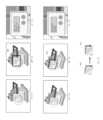
図2を参照して、表示部112の表示例を説明する。
図2(A-1)、(A-2)、(A-3)、(A-4)は、カメラ映像の時系列変化を示し、カメラ映像を構成するフレームを時系列順に並べたものである。本例では、HMDカメラ部101で右方向にパンニングするように撮影しており、カメラ映像上で被写体が左方向に移動している。A display example of the
Figures 2 (A-1), (A-2), (A-3), and (A-4) show time-series changes in camera images, and the frames that make up the camera images are arranged in chronological order. be. In this example, the HMD
図2(B-1)、(B-2)、(B-3)、(B-4)は、それぞれ(A-1)、(A-2)、(A-3)、(A-4)のフレームに対して、着目領域配置部115によって着目領域201~204がマッピングされた状態を模式的に示す。 Figures 2 (B-1), (B-2), (B-3), and (B-4) represent (A-1), (A-2), (A-3), and (A-4), respectively. ) is schematically shown in which regions of
図2(C-1)、(C-2)、(C-3)は、それぞれ(A-1)、(A-2)、(A-3)のフレームから着目領域を切り出し、着目領域の画像を拡大して表示した状態を示す。また、図2(C-4)は、(C-3)の着目領域の画像と同じものである。 Figures 2 (C-1), (C-2), and (C-3) show regions of interest cut out from frames (A-1), (A-2), and (A-3), respectively. The image is shown enlarged and displayed. Further, FIG. 2 (C-4) is the same as the image of the region of interest in (C-3).
具体的には、(B-1)の着目領域201は、(A-1)のフレームにおいて着目領域指定部114で指定された領域である。着目領域201は、着目領域指定部114で記憶した着目領域情報に基づいて、着目領域配置部115によって3次元の環境地図座標にマッピングされた領域である。着目領域201がカメラ映像のフレームの画角内にあるので、(C-1)に示すように、着目領域201の画像が拡大されて、表示部112に表示される。
(B-2)の着目領域202は、(B-1)で指定された着目領域の着目領域情報に基づいて、着目領域配置部115によって3次元の環境地図座標にマッピングされた領域である。3次元の環境地図座標は、(A-2)のフレームから空間認識部113によって算出される。着目領域202がカメラ映像のフレームの画角内にあるので、(C-2)に示すように、着目領域202の画像が拡大されて、表示部112に表示される。
(B-3)の着目領域203は、(B-1)で指定された着目領域の着目領域情報に基づいて、着目領域配置部115によって3次元の環境地図座標にマッピングされた領域である。3次元の環境地図座標は、(A-3)のフレームから空間認識部113によって算出される。着目領域203がカメラ映像のフレームの画角内にあるので、(C-3)に示すように、着目領域203の画像が拡大されて、表示部112に表示される。
図2(C-1)~(C-3)に示すように、カメラ映像のフレームの画角内に着目領域があるときは、各フレームから着目領域が順次切り出されて表示されるので、着目領域がライブビュー映像として表示される。Specifically, the region of
The region of
The region of
As shown in Figures 2 (C-1) to (C-3), when there is a region of interest within the angle of view of the frame of the camera video, the region of interest is sequentially cut out and displayed from each frame. The area is displayed as a live view image.
(B-4)の着目領域204は、(B-1)で指定された着目領域の着目領域情報に基づいて、着目領域配置部115によって3次元の環境地図座標にマッピングされた領域である。3次元の環境地図座標は、(A-4)のフレームから空間認識部113によって算出される。着目領域204がカメラ映像のフレームの画角から外れるので、(C-4)に示すように、1フレーム前の着目領域203の画像((C-3)を参照)が拡大されて、静止画像として表示部112に表示される。次に着目領域がカメラ映像のフレームの画角に入るまで、着目領域203の画像が表示部112に表示され続ける。 The region of
以上のように、カメラ映像のフレームの画角内に着目領域があるとき、当該フレームから切り出された着目領域の画像が表示され、支援者は着目領域をライブビュー映像として確認することができる。そして、カメラ映像のフレームの画角から着目領域が外れたとき、当該フレームよりも前のフレームから切り出された着目領域の画像が表示されるので、支援者は、着目領域を静止画像として継続して確認ことができる。 As described above, when a region of interest is within the angle of view of a frame of a camera image, an image of the region of interest cut out from the frame is displayed, and the supporter can confirm the region of interest as a live view video. When the area of interest deviates from the angle of view of the frame of the camera video, an image of the area of interest cut out from a frame before the frame is displayed, allowing the supporter to continue using the area of interest as a still image. You can check it.
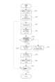
次に、図3を参照して、第1の実施形態に係る遠隔支援装置110が実行する処理について説明する。図3は、第1の実施形態に係る遠隔支援装置110が実行する処理を示すフローチャートである。
ステップS301で、表示制御部116は、受信部111で受信したカメラ映像を表示部112に表示する。
ステップS302で、着目領域指定部114は、ステップS301で表示部112に表示したカメラ映像上で着目領域の指定を受け、着目領域の座標を着目領域情報として記憶する。Next, with reference to FIG. 3, processing executed by the
In step S301, the
In step S302, the region of
ステップS303で、空間認識部113は、カメラ映像の現フレームから3次元の環境地図座標を算出する。
ステップS304で、着目領域配置部115は、ステップS302で記憶した着目領域情報に基づいて、着目領域を、ステップS303で算出した3次元の環境地図座標にマッピングする。In step S303, the
In step S304, the region of
ステップS305で、表示制御部116は、ステップS304で3次元の環境地図座標にマッピングした着目領域が、カメラ映像の現フレームの画角内にあるか否かを判定する。着目領域が画角内にあれば、ステップS306に移行し、着目領域が画角外にあれば、ステップS307に移行する。なお、着目領域が現フレームの画角内にあるか否かの判定基準は予め定めておけばよい。例えば着目領域が現フレームの画角から少しでも外れると、着目領域が画角外にあると判定するようにしてもよいし、着目領域の所定の割合の部分(例えば着目領域の半分)が現フレームの画角から外れると、着目領域が画角外にあると判定するようにしてもよい。
ステップS306で、表示制御部116は、カメラ映像の現フレームからステップS304でマッピングした着目領域を切り出し、着目領域の画像を生成する。また、表示制御部116は、この1フレーム分の着目領域の画像を保持する。
ステップS307で、表示制御部116は、保持されている着目領域の画像を取り出す。In step S305, the
In step S306, the
In step S307, the
ステップS308で、表示部112は、ステップS306で生成された着目領域の画像又はステップS307で取り出された着目領域の画像を拡大して表示部112に表示する。
ステップS309で、表示制御部116は、カメラ映像の次フレームに更新する。
ステップS310で、遠隔支援装置110は、支援者からの終了指示の有無を判定し、終了指示がない場合、ステップS303に移行し、終了指示がある場合、本フローチャートを終了する。In step S308, the
In step S309, the
In step S310, the
以上述べたように、第1の実施形態では、カメラ映像のフレームの画角から着目領域が外れたときにも、当該フレームよりも前のフレームに含まれる着目領域の画像が表示されるので、着目領域を確認することができる。これにより、作業者に対するサポートを継続して行うことが可能になる。 As described above, in the first embodiment, even when the region of interest deviates from the angle of view of the frame of the camera image, the image of the region of interest included in the frame before the frame is displayed. You can check the area of interest. This makes it possible to provide continuous support to workers.
なお、遠隔支援装置110が備えるとした構成要素を、HMDカメラ部101(又はこれが搭載されたHMD)側で備えるようにしてもよい。例えば空間認識部113や着目領域配置部115が、HMDカメラ部101(又はこれが搭載されたHMD)に設けられてもよい。
また、遠隔支援装置110の表示制御部116が、カメラ映像のフレームから着目領域を切り出し、着目領域の画像を生成する処理を実行するとしたが、この処理を、HMDカメラ部101(又はこれが搭載されたHMD)が実行するようにしてもよい。
図3のフローチャートでいえば、例えばステップS303~S307の処理を、HMDカメラ部101(又はこれが搭載されたHMD)が実行するようにしてもよい。この場合、ステップS302での指定に基づく着目領域情報を、遠隔支援装置110からHMD側に送るようにすればよい。
本実施形態では、遠隔支援装置110が本発明でいう情報処理装置として機能する例を述べたが、本発明でいう撮像装置が本発明でいう情報処理装置として機能して、支援者側のモニタの表示を制御するような形態としてもよい。Note that the components provided in the
In addition, it is assumed that the
In the flowchart of FIG. 3, for example, the processes in steps S303 to S307 may be executed by the HMD camera unit 101 (or an HMD equipped with the same). In this case, the region of interest information based on the designation in step S302 may be sent from the
In this embodiment, an example has been described in which the
(第2の実施形態)
第2の実施形態では、着目領域の画像に幾何学的変換を行う機能を有する形態について説明する。なお、遠隔支援装置110の構成は、第1の実施形態と同様であり、以下では、同一の符号を付し、その説明を省略するとともに、第1の実施形態との相違点を中心に説明する。本実施形態では、表示制御部116において、画像の幾何学的変換を行う機能が追加されており、本発明でいう画像処理手段として機能する。画像の幾何学的変換としては、例えばアフィン変換を用いる。(Second embodiment)
In the second embodiment, a configuration having a function of performing geometric transformation on an image of a region of interest will be described. Note that the configuration of the
図4(A-1)、(A-2)は、カメラ映像の時系列変化を示し、カメラ映像を構成するフレームを時系列順に並べたものである。本例では、HMDを装着した作業者が移動して、HMDカメラ部101の視野角が変わっている。この場合、カメラ映像から着目領域を切り出し、着目領域の画像を拡大して表示部112に表示するだけでは、着目領域が見えにくくなることがある。
そこで、第2の実施形態では、表示制御部116は、着目領域配置部115でマッピングした着目領域に基づいて、受信部111で受信したカメラ映像から着目領域を切り出し、着目領域指定部114で記憶した着目領域情報に基づいて、同じ画角を維持するようにアフィン変換を行った上で、着目領域の画像を拡大して表示部112に表示する制御を行う。FIGS. 4(A-1) and (A-2) show time-series changes in camera images, in which frames constituting the camera images are arranged in chronological order. In this example, the worker wearing the HMD moves and the viewing angle of the
Therefore, in the second embodiment, the
図4を参照して、表示部112の表示例を説明する。
図4(A-1)、(A-2)は、カメラ映像の時系列変化を示し、カメラ映像を構成するフレームを時系列順に並べたものである。本例では、HMDを装着した作業者が移動して、HMDカメラ部101の視野角が変わっている。A display example of the
FIGS. 4(A-1) and (A-2) show time-series changes in camera images, in which frames constituting the camera images are arranged in chronological order. In this example, the worker wearing the HMD moves and the viewing angle of the
図4(B-1)、(B-2)は、それぞれ(A-1)、(A-2)のフレームに対して、着目領域配置部115によって着目領域401、402がマッピングされた状態を模式的に示す。 4(B-1) and (B-2) show the states in which regions of
図4(C-1)は、(A-1)のフレームから着目領域を切り出し、着目領域の画像を拡大して表示した状態を示す。また、図2(C-2)は、(A-2)のフレームから着目領域を切り出し、アフィン変換を行った上で、着目領域の画像を拡大して表示した状態を示す。
具体的には、(B-1)の着目領域401は、(A-1)のフレームにおいて着目領域指定部114で指定された領域である。着目領域401は、着目領域指定部114で記憶した着目領域情報に基づいて、着目領域配置部115によって3次元の環境地図座標にマッピングされた領域である。着目領域401がカメラ映像のフレームの画角内にあるので、(C-1)に示すように、着目領域401の映像が拡大されて、ライブビュー映像として表示部112に表示される。
(B-2)の着目領域402は、(B-1)で指定された着目領域の着目領域情報に基づいて、着目領域配置部115によって3次元の環境地図座標にマッピングされた領域である。3次元の環境地図座標は、(A-2)のカメラ映像のフレームから空間認識部113によって算出される。この場合、(D-2)に示すように、着目領域402を切り出し、着目領域指定部114で記憶した着目領域情報に基づいて、同じ画角を維持するようにアフィン変換を行う(アフィン変換後の着目領域412)。着目領域402がカメラ映像のフレームの画角内にあるので、(C-2)に示すように、アフィン変換後の着目領域412の映像が拡大されて、ライブビュー映像として表示部112に表示される。FIG. 4 (C-1) shows a state in which a region of interest is cut out from the frame (A-1) and an image of the region of interest is enlarged and displayed. Further, FIG. 2 (C-2) shows a state in which the region of interest is cut out from the frame (A-2), subjected to affine transformation, and then the image of the region of interest is enlarged and displayed.
Specifically, the region of
The region of
次に、第2の実施形態に係る遠隔支援装置110が実行する処理について説明する。遠隔支援装置110が実行する処理は、基本的には図3のフローチャートと同様であるが、ステップS306において、アフィン変換の処理が追加される。
第2の実施形態におけるステップS306で、表示制御部116は、カメラ映像の現フレームからステップS304でマッピングした着目領域を切り出し、着目領域指定部114で指定された着目領域の着目領域情報に基づいて、同じ画角を維持するようにアフィン変換を行った上で、着目領域の画像を生成する。また、表示制御部116は、この1フレーム分の着目領域の画像を保持する。Next, processing executed by the
In step S306 in the second embodiment, the
以上述べたように、第2の実施形態では、第1の実施形態と同様、カメラ映像のフレームの画角から着目領域が外れたときにも、当該フレームよりも前のフレームに含まれる着目領域の画像が表示されるので、着目領域を確認することができる。これにより、作業者に対するサポートを継続して行うことが可能になる。
また、第2の実施形態では、HMDを装着した作業者が移動する等して、HMDカメラ部101の視野角が変わったときにも、着目領域の画像を同じ画角に維持することができ、見やすい映像を提供することができる。As described above, in the second embodiment, as in the first embodiment, even when the region of interest deviates from the angle of view of the frame of the camera image, the region of interest included in the frame before the frame is Since the image is displayed, you can check the area of interest. This makes it possible to provide continuous support to workers.
Furthermore, in the second embodiment, even when the viewing angle of the
(第3の実施形態)
第3の実施形態では、複数の着目領域を指定し、所望の着目領域を選択して表示する機能を有する形態について説明する。なお、遠隔支援装置110の構成は、第1の実施形態と同様であり、以下では、同一の符号を付し、その説明を省略するとともに、第1の実施形態との相違点を中心に説明する。本実施形態では、着目領域指定部114において、複数の着目領域を指定し、それぞれの着目領域情報を記憶する機能が追加されている。そして、表示制御部116において、複数の着目領域の画像をワイプ表示し、ワイプ表示の中から選択されたものをメイン映像として大きく表示する機能が追加されている。(Third embodiment)
In the third embodiment, a mode having a function of specifying a plurality of regions of interest and selecting and displaying a desired region of interest will be described. Note that the configuration of the
本実施形態では、着目領域指定部114は、表示部112に表示されたカメラ映像上で複数の着目領域の指定を受け、それぞれの着目領域情報を記憶する。
表示制御部116は、着目領域配置部115でマッピングした着目領域に基づいて、受信部111で受信したカメラ映像から着目領域を切り出し、着目領域の画像をリサイズして表示部112にワイプ表示する制御を行う。この場合に、第1の実施形態と同様、表示制御部116は、カメラ映像のフレームの画角内に着目領域があるとき、当該フレームから着目領域を切り出し、着目領域の画像をリサイズして表示部112にワイプ表示する。表示制御部116は、複数の着目領域について、1フレーム分の着目領域の画像を保持する機能を有し、カメラ映像のフレームから着目領域を切り出すたびに、保持する着目領域の画像を最新のものに更新する。また、表示制御部116は、カメラ映像のフレームの画角から着目領域が外れたとき、保持されている着目領域の画像、すなわち当該フレームよりも前のフレームの着目領域の画像をリサイズして表示部112にワイプ表示する。そして、表示制御部116は、ワイプ表示の中から選択されたものをメイン映像として大きく表示する制御を行う。In this embodiment, the region-of-
The
図5を参照して、表示部112の表示例を説明する。
図5(A)は、カメラ映像のフレームを示す。
図5(B)は、(A)のフレームに対して、着目領域配置部115によって複数の着目領域501~503がマッピングされた状態を模式的に示す。
図5(C)は、(A)のフレームから複数の着目領域を切り出し、着目領域の画像511~513をワイプ表示した状態を示す。また、ワイプ表示の中から選択された画像、ここでは画像511をメイン映像510として大きく表示した状態を示す。A display example of the
FIG. 5(A) shows a frame of a camera image.
FIG. 5B schematically shows a state in which a plurality of regions of
FIG. 5C shows a state in which a plurality of regions of interest are cut out from the frame of FIG. 5A, and
次に、図6を参照して、第3の実施形態に係る遠隔支援装置110が実行する処理について説明する。図6は、第3の実施形態に係る遠隔支援装置110が実行する処理を示すフローチャートである。なお、ステップS601、S603、S609、及びステップS610は、第1の実施形態のステップS301、S303、S309、及びS310と同様の処理であり、その説明は省略する。
ステップS602で、着目領域指定部114は、ステップS601で表示部112に表示したカメラ映像上で複数の着目領域の指定を受け、それぞれの着目領域の座標を着目領域情報として記憶する。
ステップS604で、着目領域配置部115は、ステップS602で記憶した複数の着目領域情報に基づいて、複数の着目領域を、ステップS603で算出した3次元の環境地図座標にマッピングする。Next, with reference to FIG. 6, processing executed by the
In step S602, the region of
In step S604, the region of
ステップS605で、表示制御部116は、ステップS604で3次元の環境地図座標にマッピングした複数の着目領域のうちの対象とする着目領域が、カメラ映像の現フレームの画角内にあるか否かを判定する。着目領域が画角内にあれば、ステップS606に移行し、着目領域が画角外にあれば、ステップS607に移行する。なお、着目領域が現フレームの画角内にあるか否かの判定基準については第1の実施形態で述べたとおりである。後述するステップS611で、複数の着目領域は順次処理される。
ステップS606で、表示制御部116は、カメラ映像の現フレームからステップS604でマッピングした着目領域を切り出し、着目領域の画像を生成する。また、表示制御部116は、この1フレーム分の着目領域の画像を保持する。
ステップS607で、表示制御部116は、保持されている着目領域の画像を取り出す。
ステップS611で、表示制御部116は、ステップS602で指定した複数の着目領域情報が全て処理されたかを否かを判定する。全て処理されていた場合、ステップS612に移行し、全て処理されていない場合、ステップS605に移行する。In step S605, the
In step S606, the
In step S607, the
In step S611, the
ステップS612で、表示制御部116は、ステップS306で生成された着目領域の画像又はステップS307で取り出された着目領域の画像をリサイズして表示部112にワイプ表示する。
ステップS613で、表示制御部116は、ステップS612で表示したワイプ表示の中から選択されているものをメイン映像として大きく表示する(メイン表示)。In step S612, the
In step S613, the
以上述べたように、第3の実施形態では、第1の実施形態と同様、カメラ映像のフレームの画角から着目領域が外れたときにも、当該フレームよりも前のフレームに含まれる着目領域の画像が表示されるので、着目領域を確認することができる。これにより、作業者に対するサポートを継続して行うことが可能になる。
また、第3の実施形態では、複数の着目領域を指定し、所望の着目領域を選択して表示することができるので、遠隔支援の効率を向上させることができる。As described above, in the third embodiment, as in the first embodiment, even when the region of interest deviates from the angle of view of the frame of the camera image, the region of interest included in the frame before the frame is Since the image is displayed, you can check the area of interest. This makes it possible to provide continuous support to workers.
Further, in the third embodiment, it is possible to specify a plurality of regions of interest and select and display a desired region of interest, thereby improving the efficiency of remote support.
以上、各種実施形態を説明したが、以下のような機能を追加してもよい。
例えば、支援者が指定してマッピングされた着目領域を示す情報をHMD側に送信し、HMDパネルで着目領域を枠等で表示することで、作業者側でも支援者が指定した着目領域を認識することができる。Although various embodiments have been described above, the following functions may be added.
For example, by transmitting information indicating the mapped area of interest specified by the supporter to the HMD side and displaying the area of interest in a frame etc. on the HMD panel, the worker can also recognize the area of interest specified by the supporter. can do.
また、図7に示すように、表示部112に表示する着目領域の画像が、着目領域が画角内にあるときの画像であるのか、画角外にあるときの画像であるのかを明示する。図7(C-1)、(C-2)は、着目領域の画像を拡大して表示した状態を示す。図7(C-1)では、着目領域が画角内にあるときの画像(ライブビュー映像)であることを示すマーク701を表示している。また、図7(C-2)は、着目領域が画角外にあるときの画像(静止画像)であることを示すマーク702を表示している。 Further, as shown in FIG. 7, it is clearly indicated whether the image of the region of interest displayed on the
以上、本発明を実施形態と共に説明したが、上記実施形態は本発明を実施するにあたっての具体化の例を示したものに過ぎず、これらによって本発明の技術的範囲が限定的に解釈されてはならないものである。すなわち、本発明はその技術思想、又はその主要な特徴から逸脱することなく、様々な形で実施することができる。
(その他の実施形態)
本発明は、上述の実施形態の1以上の機能を実現するプログラムを、ネットワーク又は記憶媒体を介してシステム又は装置に供給し、そのシステム又は装置のコンピュータにおける1つ以上のプロセッサーがプログラムを読出し実行する処理でも実現可能である。また、1以上の機能を実現する回路(例えば、ASIC)によっても実現可能である。Although the present invention has been described above along with the embodiments, the above embodiments are merely examples of implementation of the present invention, and the technical scope of the present invention should not be construed as limited by these embodiments. This is something that should not happen. That is, the present invention can be implemented in various forms without departing from its technical idea or main features.
(Other embodiments)
The present invention provides a system or device with a program that implements one or more of the functions of the embodiments described above via a network or a storage medium, and one or more processors in the computer of the system or device reads and executes the program. This can also be achieved by processing. It can also be realized by a circuit (for example, ASIC) that realizes one or more functions.
本実施の形態の開示は、以下の構成及び方法を含む。
[構成1]
撮像装置による撮影映像を表示部に表示する情報処理装置であって、
前記撮影映像に含まれる着目領域の画像を前記表示部に表示するように制御する表示制御手段を備え、
前記表示制御手段は、
前記撮影映像のフレームの画角内に前記着目領域があるとき、当該フレームに含まれる前記着目領域の画像を表示し、
前記撮影映像のフレームの画角から前記着目領域が外れたとき、当該フレームよりも前のフレームに含まれる前記着目領域の画像を表示することを特徴とする情報処理装置。
[構成2]
前記撮影映像から空間を認識する空間認識手段と、
前記着目領域を、前記空間認識手段で認識した前記空間にマッピングする着目領域配置手段とを備えたことを特徴とする構成1に記載の情報処理装置。
[構成3]
前記撮影映像に基づいて着目領域を指定する着目領域指定手段を備えたことを特徴とする構成1又は2に記載の情報処理装置。
[構成4]
前記着目領域の画像に幾何学的変換を行う画像処理手段を備えたことを特徴とする構成1乃至3のいずれか1つに記載の情報処理装置。
[構成5]
前記着目領域が複数あり、
前記表示制御手段は、複数の前記着目領域の画像をワイプ表示し、前記ワイプ表示の中から選択されたものを大きく表示することを特徴とする構成1乃至4のいずれか1つに記載の情報処理装置。
[構成6]
前記表示制御手段は、前記着目領域の画像が、前記着目領域が画角内にあるときの画像であるのか、画角外にあるときの画像であるのかを明示することを特徴とする構成1乃至5のいずれか1つに記載の情報処理装置。
[構成7]
前記撮像装置は、ヘッドマウントディスプレイに搭載されたデジタルカメラであることを特徴とする構成1乃至6のいずれか1つに記載の情報処理装置。
[方法]
撮像装置による撮影映像を表示部に表示する情報処理装置が実行する情報処理方法であって、
前記撮影映像に含まれる着目領域の画像を前記表示部に表示するように制御する表示制御ステップを有し、
前記表示制御ステップでは、
前記撮影映像のフレームの画角内に前記着目領域があるとき、当該フレームに含まれる前記着目領域の画像を表示し、
前記撮影映像のフレームの画角から前記着目領域が外れたとき、当該フレームよりも前のフレームに含まれる前記着目領域の画像を表示することを特徴とする情報処理方法。
[プログラム]
撮像装置による撮影映像を表示部に表示するためのプログラムであって、
前記撮影映像に含まれる着目領域の画像を前記表示部に表示するように制御する表示制御手段としてコンピュータを機能させ、
前記表示制御手段は、
前記撮影映像のフレームの画角内に前記着目領域があるとき、当該フレームに含まれる前記着目領域の画像を表示し、
前記撮影映像のフレームの画角から前記着目領域が外れたとき、当該フレームよりも前のフレームに含まれる前記着目領域の画像を表示することを特徴とするプログラム。
[構成8]
撮像装置による撮影映像を表示部に表示するネットワークシステムであって、
前記撮影映像から空間を認識する空間認識手段と、
前記撮影映像に含まれる着目領域を、前記空間認識手段で認識した前記空間にマッピングする着目領域配置手段と、
前記着目領域の画像を前記表示部に表示するように制御する表示制御手段を備え、
前記表示制御手段は、
前記撮影映像のフレームの画角内に前記着目領域があるとき、当該フレームに含まれる前記着目領域の画像を表示し、
前記撮影映像のフレームの画角から前記着目領域が外れたとき、当該フレームよりも前のフレームに含まれる前記着目領域の画像を表示することを特徴とするネットワークシステム。The disclosure of this embodiment includes the following configuration and method.
[Configuration 1]
An information processing device that displays images shot by an imaging device on a display unit,
comprising display control means for controlling an image of a region of interest included in the photographed video to be displayed on the display unit;
The display control means includes:
When the region of interest is within the angle of view of a frame of the photographed video, displaying an image of the region of interest included in the frame;
An information processing device characterized in that, when the region of interest deviates from the angle of view of a frame of the photographed video, an image of the region of interest included in a frame before the frame is displayed.
[Configuration 2]
space recognition means for recognizing space from the captured video;
The information processing apparatus according to
[Configuration 3]
The information processing apparatus according to
[Configuration 4]
4. The information processing apparatus according to any one of
[Configuration 5]
There are multiple areas of interest,
Information according to any one of
[Configuration 6]
[Configuration 7]
7. The information processing device according to any one of
[Method]
An information processing method executed by an information processing device that displays images shot by an imaging device on a display unit, the method comprising:
a display control step for controlling an image of a region of interest included in the photographed video to be displayed on the display unit;
In the display control step,
When the region of interest is within the angle of view of a frame of the photographed video, displaying an image of the region of interest included in the frame;
An information processing method characterized in that when the region of interest deviates from the angle of view of a frame of the photographed video, an image of the region of interest included in a frame before the frame is displayed.
[program]
A program for displaying images shot by an imaging device on a display unit,
causing a computer to function as a display control means for controlling an image of a region of interest included in the photographed video to be displayed on the display unit;
The display control means includes:
When the region of interest is within the angle of view of a frame of the photographed video, displaying an image of the region of interest included in the frame;
A program characterized in that, when the region of interest deviates from the angle of view of a frame of the photographed video, an image of the region of interest included in a frame before the frame is displayed.
[Configuration 8]
A network system that displays images shot by an imaging device on a display unit,
space recognition means for recognizing space from the captured video;
a region of interest placement means for mapping a region of interest included in the photographed video onto the space recognized by the space recognition means;
comprising display control means for controlling the image of the region of interest to be displayed on the display unit,
The display control means includes:
When the region of interest is within the angle of view of a frame of the photographed video, displaying an image of the region of interest included in the frame;
A network system characterized in that when the region of interest deviates from the angle of view of a frame of the photographed video, an image of the region of interest included in a frame before the frame is displayed.
101:HMDカメラ部、110:遠隔支援装置、111:受信部、112:表示部、113:空間認識部、114:着目領域指定部、115:着目領域配置部、116:表示制御部、117:バス 101: HMD camera section, 110: remote support device, 111: receiving section, 112: display section, 113: spatial recognition section, 114: region of interest designation section, 115: region of interest placement section, 116: display control section, 117: bus
Claims (10)
Translated fromJapanese前記撮影映像に含まれる着目領域の画像を前記表示部に表示するように制御する表示制御手段を備え、
前記表示制御手段は、
前記撮影映像のフレームの画角内に前記着目領域があるとき、当該フレームに含まれる前記着目領域の画像を表示し、
前記撮影映像のフレームの画角から前記着目領域が外れたとき、当該フレームよりも前のフレームに含まれる前記着目領域の画像を表示することを特徴とする情報処理装置。An information processing device that displays images shot by an imaging device on a display unit,
comprising display control means for controlling an image of a region of interest included in the photographed video to be displayed on the display unit;
The display control means includes:
When the region of interest is within the angle of view of a frame of the photographed video, displaying an image of the region of interest included in the frame;
An information processing device characterized in that, when the region of interest deviates from the angle of view of a frame of the photographed video, an image of the region of interest included in a frame before the frame is displayed.
前記着目領域を、前記空間認識手段で認識した前記空間にマッピングする着目領域配置手段とを備えたことを特徴とする請求項1に記載の情報処理装置。space recognition means for recognizing space from the captured video;
The information processing apparatus according to claim 1, further comprising a region of interest placement means for mapping the region of interest onto the space recognized by the space recognition means.
前記表示制御手段は、複数の前記着目領域の画像をワイプ表示し、前記ワイプ表示の中から選択されたものを大きく表示することを特徴とする請求項1又は2に記載の情報処理装置。There are multiple areas of interest,
3. The information processing apparatus according to claim 1, wherein the display control means wipe-displays the images of the plurality of regions of interest, and displays a selected one from the wipe-display in a large size.
前記撮影映像に含まれる着目領域の画像を前記表示部に表示するように制御する表示制御ステップを有し、
前記表示制御ステップでは、
前記撮影映像のフレームの画角内に前記着目領域があるとき、当該フレームに含まれる前記着目領域の画像を表示し、
前記撮影映像のフレームの画角から前記着目領域が外れたとき、当該フレームよりも前のフレームに含まれる前記着目領域の画像を表示することを特徴とする情報処理方法。An information processing method executed by an information processing device that displays images shot by an imaging device on a display unit, the method comprising:
a display control step for controlling an image of a region of interest included in the photographed video to be displayed on the display unit;
In the display control step,
When the region of interest is within the angle of view of a frame of the photographed video, displaying an image of the region of interest included in the frame;
An information processing method characterized in that when the region of interest deviates from the angle of view of a frame of the photographed video, an image of the region of interest included in a frame before the frame is displayed.
前記撮影映像に含まれる着目領域の画像を前記表示部に表示するように制御する表示制御手段としてコンピュータを機能させ、
前記表示制御手段は、
前記撮影映像のフレームの画角内に前記着目領域があるとき、当該フレームに含まれる前記着目領域の画像を表示し、
前記撮影映像のフレームの画角から前記着目領域が外れたとき、当該フレームよりも前のフレームに含まれる前記着目領域の画像を表示することを特徴とするプログラム。A program for displaying images shot by an imaging device on a display unit,
causing a computer to function as a display control means for controlling an image of a region of interest included in the photographed video to be displayed on the display unit;
The display control means includes:
When the region of interest is within the angle of view of a frame of the photographed video, displaying an image of the region of interest included in the frame;
A program characterized in that, when the region of interest deviates from the angle of view of a frame of the photographed video, an image of the region of interest included in a frame before the frame is displayed.
前記撮影映像から空間を認識する空間認識手段と、
前記撮影映像に含まれる着目領域を、前記空間認識手段で認識した前記空間にマッピングする着目領域配置手段と、
前記着目領域の画像を前記表示部に表示するように制御する表示制御手段を備え、
前記表示制御手段は、
前記撮影映像のフレームの画角内に前記着目領域があるとき、当該フレームに含まれる前記着目領域の画像を表示し、
前記撮影映像のフレームの画角から前記着目領域が外れたとき、当該フレームよりも前のフレームに含まれる前記着目領域の画像を表示することを特徴とするネットワークシステム。A network system that displays images shot by an imaging device on a display unit,
space recognition means for recognizing space from the captured video;
a region of interest arrangement means for mapping a region of interest included in the photographed video onto the space recognized by the space recognition means;
comprising display control means for controlling the image of the region of interest to be displayed on the display unit,
The display control means includes:
When the region of interest is within the angle of view of a frame of the photographed video, displaying an image of the region of interest included in the frame;
A network system characterized in that when the region of interest deviates from the angle of view of a frame of the photographed video, an image of the region of interest included in a frame before the frame is displayed.
Priority Applications (2)
| Application Number | Priority Date | Filing Date | Title |
|---|---|---|---|
| JP2022064560AJP2023154916A (en) | 2022-04-08 | 2022-04-08 | Information processing device, method, and program |
| US18/296,262US12279049B2 (en) | 2022-04-08 | 2023-04-05 | Information processing apparatus displaying captured image for remote support of an operation by an operator |
Applications Claiming Priority (1)
| Application Number | Priority Date | Filing Date | Title |
|---|---|---|---|
| JP2022064560AJP2023154916A (en) | 2022-04-08 | 2022-04-08 | Information processing device, method, and program |
Publications (2)
| Publication Number | Publication Date |
|---|---|
| JP2023154916Atrue JP2023154916A (en) | 2023-10-20 |
| JP2023154916A5 JP2023154916A5 (en) | 2025-04-11 |
Family
ID=88239053
Family Applications (1)
| Application Number | Title | Priority Date | Filing Date |
|---|---|---|---|
| JP2022064560APendingJP2023154916A (en) | 2022-04-08 | 2022-04-08 | Information processing device, method, and program |
Country Status (2)
| Country | Link |
|---|---|
| US (1) | US12279049B2 (en) |
| JP (1) | JP2023154916A (en) |
Family Cites Families (16)
| Publication number | Priority date | Publication date | Assignee | Title |
|---|---|---|---|---|
| US20040223649A1 (en)* | 2003-05-07 | 2004-11-11 | Eastman Kodak Company | Composite imaging method and system |
| US20050129324A1 (en)* | 2003-12-02 | 2005-06-16 | Lemke Alan P. | Digital camera and method providing selective removal and addition of an imaged object |
| US7634106B2 (en)* | 2004-09-22 | 2009-12-15 | Fujifilm Corporation | Synthesized image generation method, synthesized image generation apparatus, and synthesized image generation program |
| JP2007148548A (en) | 2005-11-24 | 2007-06-14 | Murata Mach Ltd | Three-dimensional region designation method |
| JP4853320B2 (en)* | 2007-02-15 | 2012-01-11 | ソニー株式会社 | Image processing apparatus and image processing method |
| JP4396720B2 (en)* | 2007-03-26 | 2010-01-13 | ソニー株式会社 | Image processing apparatus, image processing method, and program |
| US8041076B1 (en)* | 2007-08-09 | 2011-10-18 | Adobe Systems Incorporated | Generation and usage of attractiveness scores |
| JP2010086178A (en)* | 2008-09-30 | 2010-04-15 | Fujifilm Corp | Image synthesis device and control method thereof |
| JP2014123261A (en)* | 2012-12-21 | 2014-07-03 | Sony Corp | Information processor and recording medium |
| JP6103526B2 (en)* | 2013-03-15 | 2017-03-29 | オリンパス株式会社 | Imaging device, image display device, and display control method for image display device |
| JP6429454B2 (en)* | 2013-11-28 | 2018-11-28 | キヤノン株式会社 | IMAGING DEVICE, IMAGING DEVICE CONTROL METHOD, AND IMAGING DEVICE CONTROL PROGRAM |
| KR102352681B1 (en)* | 2015-07-27 | 2022-01-18 | 삼성전자주식회사 | Method and electronic apparatus for stabilizing video |
| JP6590628B2 (en)* | 2015-10-09 | 2019-10-16 | キヤノン株式会社 | IMAGING DEVICE, ITS CONTROL METHOD, PROGRAM, AND STORAGE MEDIUM |
| JP6696925B2 (en) | 2017-03-16 | 2020-05-20 | Kddi株式会社 | Operation support device |
| JP2021013138A (en) | 2019-07-09 | 2021-02-04 | キヤノン株式会社 | Imaging equipment and information processing equipment |
| JP7559810B2 (en)* | 2022-08-10 | 2024-10-02 | カシオ計算機株式会社 | Image processing device, image processing method, and program |
- 2022
- 2022-04-08JPJP2022064560Apatent/JP2023154916A/enactivePending
- 2023
- 2023-04-05USUS18/296,262patent/US12279049B2/enactiveActive
Also Published As
| Publication number | Publication date |
|---|---|
| US12279049B2 (en) | 2025-04-15 |
| US20230328394A1 (en) | 2023-10-12 |
Similar Documents
| Publication | Publication Date | Title |
|---|---|---|
| JP6587113B2 (en) | Image processing apparatus and image processing method | |
| US10095458B2 (en) | Information processing apparatus, information processing method, non-transitory computer-readable storage medium, and system | |
| JP5740884B2 (en) | AR navigation for repeated shooting and system, method and program for difference extraction | |
| KR101899877B1 (en) | Apparatus and method for improving quality of enlarged image | |
| KR101915369B1 (en) | Display control apparatus and computer-readable recording medium | |
| CN104272726B (en) | Display image forming apparatus and display image forming method | |
| JP2016062486A (en) | Image generation device and image generation method | |
| KR20010072917A (en) | All-around video output method and device | |
| JP2016167688A (en) | Image generation method, system, device, and terminal | |
| JP2002209208A (en) | Image processing unit and its method, and storage medium | |
| JP2012089954A (en) | Conference system, monitoring system, image processing system, image processing method, and image processing program or the like | |
| JP2007072537A (en) | 360 ° image capturing device | |
| JP2025031790A (en) | Display system, display method, and program for remote operation | |
| JP6269014B2 (en) | Focus control device and focus control method | |
| JP2008244946A (en) | Image display apparatus, image display control method, program, and monitoring camera system | |
| JP2023154916A (en) | Information processing device, method, and program | |
| JP2021060856A (en) | Image synthesis apparatus, control method thereof, and program | |
| JP2012216935A (en) | Information processing system, search device and program | |
| JP2021040231A (en) | Image processing device and program | |
| JP2005268972A (en) | Video display system and video display method | |
| WO2018016655A1 (en) | Instructing device, method of controlling instructing device, remote operation support system, and information processing program | |
| KR101438459B1 (en) | A Method for Synchronizing Opticla Axis of 3D Map and Camera Image and Monitoring System Using the Same | |
| KR20120048343A (en) | Method and apparatus for providing panorama image | |
| JP6815878B2 (en) | Image processing equipment, image processing methods, and programs | |
| CN116016890B (en) | Image display method, system, device and equipment |
Legal Events
| Date | Code | Title | Description |
|---|---|---|---|
| A521 | Request for written amendment filed | Free format text:JAPANESE INTERMEDIATE CODE: A523 Effective date:20250403 | |
| A621 | Written request for application examination | Free format text:JAPANESE INTERMEDIATE CODE: A621 Effective date:20250403 |