JP2023151423A - container with spatula - Google Patents
container with spatulaDownload PDFInfo
- Publication number
- JP2023151423A JP2023151423AJP2022061016AJP2022061016AJP2023151423AJP 2023151423 AJP2023151423 AJP 2023151423AJP 2022061016 AJP2022061016 AJP 2022061016AJP 2022061016 AJP2022061016 AJP 2022061016AJP 2023151423 AJP2023151423 AJP 2023151423A
- Authority
- JP
- Japan
- Prior art keywords
- container
- spatula
- wall
- cap
- inner container
- Prior art date
- Legal status (The legal status is an assumption and is not a legal conclusion. Google has not performed a legal analysis and makes no representation as to the accuracy of the status listed.)
- Pending
Links
- 230000002093peripheral effectEffects0.000claimsabstractdescription32
- 238000003780insertionMethods0.000claimsdescription8
- 230000037431insertionEffects0.000claimsdescription8
- 238000012856packingMethods0.000claimsdescription8
- 230000004308accommodationEffects0.000claimsdescription4
- 230000000630rising effectEffects0.000claimsdescription3
- 238000007789sealingMethods0.000abstract1
- 239000006071creamSubstances0.000description2
- 239000002537cosmeticSubstances0.000description1
- 230000008878couplingEffects0.000description1
- 238000010168coupling processMethods0.000description1
- 238000005859coupling reactionMethods0.000description1
- 230000000694effectsEffects0.000description1
- 238000000605extractionMethods0.000description1
Images


Landscapes
- Details Of Rigid Or Semi-Rigid Containers (AREA)
- Packages (AREA)
Abstract
Description
Translated fromJapanese本発明は、クリーム等の化粧料を収納する容器に関し、とくに、スパチュラを収容可能なスパチュラ付き容器に関するものである。 The present invention relates to a container for storing cosmetics such as creams, and particularly to a container with a spatula that can accommodate a spatula.
従来から、クリーム等の比較的粘度の高い内容物を収納する容器として、スパチュラ(へら)を使用して内容物を取り出すように、広口状の容器本体とキャップとからなるジャータイプの容器が使用されているため、スパチュラを収容する場所が問題となる。 Jar-type containers, which consist of a wide-mouthed container body and a cap, have traditionally been used to store relatively highly viscous contents such as cream, so that the contents can be removed using a spatula. Therefore, where to house the spatula becomes an issue.
この問題に対処するため、容器本体内を密封する中蓋の上面に設けた一組の係止片間にスパチュラを挟持するようにした容器が知られている(特許文献1参照)。 In order to deal with this problem, a container is known in which a spatula is held between a pair of locking pieces provided on the upper surface of an inner lid that seals the inside of the container body (see Patent Document 1).
また、取出具(スパチュラ)を容器本体の外周面に形成される収納凹部内に収容し、蓋体(キャップ)が装着された閉蓋状態において、収納凹部内に収容されている取出具が蓋体と収納凹部との間に取り出し不能に保持される容器も知られている(特許文献2参照)。 In addition, the removal tool (spatula) is stored in the storage recess formed on the outer peripheral surface of the container body, and when the lid body (cap) is attached and the lid is closed, the removal tool (spatula) stored in the storage recess is removed from the lid. A container is also known that is held between the body and the storage recess in a manner that cannot be removed (see Patent Document 2).
しかしながら、特許文献1に記載の容器は、スパチュラを容器本体の中蓋に収容するため、スパチュラの全長に制約を受けることになり、全長が短い場合には、スパチュラとして使い難くなるという問題があった。 However, in the container described in
また特許文献2に記載の容器は、取出具が容器本体の外周面に形成される収納凹部内に収容されるため、特許文献1に記載のスパチュラよりも全長を長くできるが、取出具の収容時に、取出具が部分的に露出するため、衛生上の問題があった。 Furthermore, in the container described in
本発明は、上記問題を解決することを課題とし、スパチュラの全長をレフィル容器または内容器の内高より長く、また容器の内径よりも長くするとともに、スパチュラを容器内に収容できるスパチュラ付き容器を提供することを目的とする。 The present invention aims to solve the above problems, and provides a container with a spatula in which the entire length of the spatula is longer than the inner height of the refill container or inner container, and longer than the inner diameter of the container, and the spatula can be accommodated within the container. The purpose is to provide.
本発明は、上記の課題を解決するため、スパチュラ付き容器として、内容物または内容物を充填したレフィル容器を収納する内容器と、内容器の外側を覆う外容器と、内容器内および外容器内を密封するキャップと、外容器内に収容されるスパチュラとを備えるスパチュラ付き容器であって、外容器は、底壁と、底壁の外縁から立設される外周壁と、外周壁の内周側に、内容器の外周側との間でスパチュラ収容空間を画成するガイド壁とを有し、スパチュラは、外容器の上部から周方向に下降しながらスパチュラ収容空間に沿って案内されることを特徴とする構成を採用する。 In order to solve the above-mentioned problems, the present invention provides, as a container with a spatula, an inner container that stores a content or a refill container filled with the content, an outer container that covers the outside of the inner container, and an inner container and an outer container. A spatula-equipped container comprising a cap that seals the inside and a spatula housed in the outer container, the outer container having a bottom wall, an outer peripheral wall standing from the outer edge of the bottom wall, and an inner wall of the outer peripheral wall. It has a guide wall on the circumferential side that defines a spatula accommodating space between it and the outer periphery of the inner container, and the spatula is guided along the spatula accommodating space while descending in the circumferential direction from the top of the outer container. A configuration characterized by this is adopted.
スパチュラ付き容器の実施形態として、ガイド壁は、スロープ部と、スロープ部から立ち上がるストップ部とを有することを特徴とする構成を採用し、また、内容器は、内容物または内容物を充填したレフィル容器を格納する格納部と、格納部の上部から間隔を開けて外周側に垂設されるねじ筒と、ねじ筒に開口され、スパチュラを挿入する挿入開口部とを有し、キャップは、頂壁と、頂壁の外周縁から垂設される側周壁と、側周壁の内周に螺設され、内容器のねじ筒と螺合するねじ部とを有することを特徴とする構成を採用し、また、外容器は、内容器の挿入開口部の下方からガイド壁のスロープ部を形成することを特徴とする構成を採用し、また、スパチュラは、全体が湾曲した形状をなし、先端に形成される掬い部と、掬い部の末端側に形成される載置凸部と、載置凸部から末端側に延びる持ち手部とを有し、キャップは、下面にリング状のパッキンを有し、スパチュラは、仮置き時に、キャップを裏返して掬い部をキャップ内に載置することを特徴とする構成を採用する。 As an embodiment of the container with a spatula, the guide wall has a slope part and a stop part rising from the slope part, and the inner container has a content or a refill filled with the content. The cap has a storage part that stores the container, a threaded cylinder that is vertically disposed on the outer circumferential side at a distance from the top of the storage part, and an insertion opening that is opened in the threaded cylinder and into which a spatula is inserted. Adopting a structure characterized by having a wall, a side peripheral wall that is vertically provided from the outer peripheral edge of the top wall, and a threaded part that is threaded on the inner periphery of the side peripheral wall and that is threadedly engaged with the threaded cylinder of the inner container. In addition, the outer container has a configuration in which a slope portion of the guide wall is formed from below the insertion opening of the inner container, and the spatula has a curved shape as a whole, and a slope portion is formed at the tip of the spatula. The cap has a scooping part formed on the distal side of the scooping part, a placing convex part formed on the distal side of the scooping part, and a handle part extending from the placing convex part toward the distal side, and the cap has a ring-shaped packing on the lower surface. , the spatula adopts a configuration characterized in that when temporarily placed, the cap is turned over and the scooping part is placed inside the cap.
本発明のスパチュラ付き容器は、上記構成を採用することにより、内容器と外容器との間にスパチュラを収容することで、容器の使用中にスパチュラを無くしたり汚したりせず、また、スパチュラの全長をレフィル容器または内容器の内高より長く、また容器の内径よりも長くすることができる。 By adopting the above structure, the container with a spatula of the present invention accommodates the spatula between the inner container and the outer container, thereby preventing the spatula from being lost or soiled while the container is in use. The total length can be made longer than the inner height of the refill container or inner container, and also longer than the inner diameter of the container.
次に、本発明のスパチュラ付き容器について、実施例を示した図面を参照して説明する。
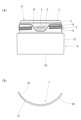
なお、以下の説明において、図1(a)でみて、上方向を「上」、下方向を「下」、右方向を「正面側」、左方向を「背面側」とする。Next, the container with a spatula of the present invention will be explained with reference to the drawings showing examples.
In the following description, as seen in FIG. 1(a), the upper direction is referred to as "top", the lower direction as "lower", the right direction as "front side", and the left direction as "rear side".
図1において、Aはスパチュラ付き容器であり、内容物を収納するレフィル容器Bと、レフィル容器Bを取り替え可能に格納する内容器Cと、内容器Cの外側を覆う外容器Dと、内容器Cおよび外容器D内を密封するキャップEと、内容器Cと外容器Dの間に収容され、内容物を取り出すスパチュラFとを備えている。 In FIG. 1, A is a container with a spatula, which includes a refill container B that stores the contents, an inner container C that stores the refill container B in a replaceable manner, an outer container D that covers the outside of the inner container C, and an inner container. C and an outer container D, and a spatula F that is housed between the inner container C and the outer container D and takes out the contents.
レフィル容器Bは、図1~図3に示すように、内容物を収納する有底円筒状の収納部1と、収納部1の口部1aから径方向外方に向けて形成される上面視でリング状のフランジ2と、フランジ2の外縁から垂設される係止壁3とを備えている。
係止壁3は、図2(b)に示すように、正面側に1個所の切り欠き部4が凹設され、また、図3(a)に示すように、背面側に係止壁3の下端から延長部5が垂設され、延長部5の外周面には、位置決め用の摘み部6が形成されている。As shown in FIGS. 1 to 3, the refill container B includes a bottomed
As shown in FIG. 2(b), the
内容器Cは、図1~図3に示すように、レフィル容器Bを格納する有底円筒状の格納部10と、格納部10の下端外縁から垂設され、外周面に嵌合凹部11aが形成される嵌合筒11と、格納部10の上端から立設され、レフィル容器Bの係止壁3の内周と係合する装着筒12と、格納部10の上端から径方向外方に向けて形成されるリング壁13と、リング壁13の外縁から垂下され、外周面に雄ねじ部15が螺設されるねじ筒14と、ねじ筒14の下端から僅かに拡径して垂下される外筒壁16と、外筒壁16の上端から径方向外方に向けて形成される係止突条17とを備えている。 As shown in FIGS. 1 to 3, the inner container C includes a bottomed
ねじ筒14は、図2(b)に示すように、正面側の所定範囲が上端から係止壁3の切り欠き部4と連続するように切り込まれ、スパチュラFを挿入する矩形状の挿入開口部18が形成されるとともに、図3(a)に示すように、背面側の所定範囲が上端から切り込まれ、レフィル容器Bの係止壁3の延長部5が露出する逆台形状の位置決め切り欠き部19が形成されている。
なお、以上の説明では、内容器Cは、内容物を収納するレフィル容器Bを取り替え可能に格納する場合について説明したが、内容器Cは、内容物を直接収納するようにしても構わない。As shown in FIG. 2(b), the threaded
In the above description, the case where the inner container C stores the refill container B that stores the contents in a replaceable manner is explained, but the inner container C may directly store the contents.
外容器Dは、図1および図2に示すように、円板状の底壁20と、底壁20の外縁から立設される円筒状の外周壁21と、外周壁21と所定の間隔を開けて底壁20から立設される取り付け筒22とを備えている。
外周壁21は、内容器Cの外筒壁16の係止突条17と係合する係止段部21aが形成され、さらに、取り付け筒22の内周面には、内容器Cの嵌合筒11の嵌合凹部11aと係合する係合突部23が形成されている。As shown in FIGS. 1 and 2, the outer container D includes a disc-
The outer
外容器Dは、外周壁21の内周側に、内容器Cの外筒壁16の厚みに相当する間隔を隔て、取り付け筒22の外周に沿ってガイド壁24が底壁20から立設されている。
ガイド壁24は、図2(b)に示すように、外周壁21と同等の高さに形成され、内容器Cの挿入開口部18の下方からスロープ部25が周方向下方に傾斜しながら形成され、図1(a)に示すように、スロープ部25の下端は、底壁20の上面と一致するフラット部26と接続した後、直ちにストップ部27が垂直に形成され、ガイド壁24に形成されるスロープ部25と、フラット部26と、ストップ部27とによってスパチュラ収容空間αが画成されている。
なお、ガイド壁24のスパチュラ収容空間αは、スロープ部25と、スロープ部25から立ち上がるストップ部27とで画成されれば十分であり、フラット部26は、スロープ部25の傾斜角度やスパチュラFの大きさなどに応じて、適宜設けることができる。The outer container D has a
The
Note that it is sufficient that the spatula accommodation space α of the
キャップEは、図4に示すように、円板状の頂壁30と、頂壁30の外周縁から垂設される側周壁31とを備え、側周壁31の内周面には、内容器Cのねじ筒14に螺設された雄ねじ部15と螺合する雌ねじ部32が螺設されている。
なお、本実施例では、キャップEは、内容器Cのねじ筒14に螺設された雄ねじ部15と螺合するねじキャップとしているが、ねじキャップに限らず、アンダーカット嵌合するタイプのキャップであっても構わない。As shown in FIG. 4, the cap E includes a disk-shaped
In this embodiment, the cap E is a screw cap that screws into the male threaded
頂壁30の下面には、中央が開口するリング状のパッキンPが装着され、キャップEによって内容器Cが閉蓋された際に、パッキンPは、レフィル容器Bのフランジ2上面と密着して内容器Cおよび外容器D内を密封する。 A ring-shaped packing P with an open center is attached to the lower surface of the
スパチュラFは、図1(a)および図3(b)に示すように、全体として湾曲形状をなし、一定の幅を有する持ち手部40と、持ち手部40の先端側外周面に形成される載置凸部41と、載置凸部41の先端側に形成され、持ち手部40よりも幅広で、内周面が凹面状の掬い部42とを備えている。 As shown in FIGS. 1(a) and 3(b), the spatula F has a curved shape as a whole and includes a
次に、本実施例の使用態様と作用効果について説明する。
本実施例のスパチュラ付き容器Aは、内容器Cを外容器Dの上方から装着し、内容器Cの嵌合筒11を外容器Dの取り付け筒22に嵌合すると同時に、内容器Cの外筒壁16を外容器Dの外周壁21とガイド壁24との間隙に挿入し、外筒壁16の係止突条17を外周壁21の係止段部21aに係止することにより、内容器Cと外容器Dとの組み付けが完了する。Next, the usage mode and effects of this embodiment will be explained.
In the container A with a spatula of this embodiment, the inner container C is attached from above the outer container D, and the
その後、図2(b)に示すように、内容器Cの挿入開口部18から、スパチュラFをガイド壁24のスロープ部25に沿って、掬い部42から挿入すると、図1(a)に示すように、スパチュラFは、先端の掬い部42がフラット部26まで達し、ストップ部27に当接し、それ以上挿入することができなくなり、スパチュラFの挿入が完了する。 Thereafter, as shown in FIG. 2(b), the spatula F is inserted from the
次に、内容物が収納部1に充填されたレフィル容器Bを、内容器Cの格納部10内に挿入し、図2(b)に示すように、内容器Cの装着筒12をレフィル容器Bの収納部1の外周上部と係止壁3の内周とで狭持するとともに、レフィル容器Bの係止壁3の延長部5に形成される摘み部6を掴み、延長部5が内容器Cの位置決め切り欠き部19に合致するように位置決めしてレフィル容器Bの装着が完了する。 Next, the refill container B whose
最後に、キャップEを内容器Cのねじ筒14に螺合することで、スパチュラFを収容したスパチュラ付き容器Aとなる。
その際、スパチュラFは、ガイド壁24によって画成されるスパチュラ収容空間αに沿って保持され、スパチュラFが動かないようになっている。Finally, by screwing the cap E onto the threaded
At this time, the spatula F is held along the spatula accommodation space α defined by the
次に、内容物を使用する際には、キャップEを内容器Cに対して回転させ、内容器Cのねじ筒14と螺脱し、開蓋することで、レフィル容器Bの口部1aから内容物を取り出すことができる。
また、キャップEの開蓋後は、挿入開口部18から露出するスパチュラFの持ち手部40を掴み、スパチュラFを引き出すことにより、スパチュラFの掬い部42で内容物を取り出すことができる。スパチュラFは湾曲しており、全長をレフィル容器Bまたは内容器Cの内高より長く、また外容器Dの内径よりも長くしているため、レフィル容器Bや内容器Cに収納された内容物が残り少なくなった時でも容易に取り出すことができ、使い勝手がよい。Next, when using the contents, the cap E is rotated relative to the inner container C, unscrewed from the threaded
Further, after opening the cap E, the contents can be taken out with the scooping
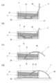
本実施例のスパチュラ付き容器Aでは、スパチュラFを使用中は、図5(a)~図5(d)に示すパターン1~4のように、裏返したキャップEおよびパッキンPを利用してスパチュラFを仮置きすることができる。 In the container A with a spatula of this embodiment, when the spatula F is in use, as shown in
すなわち、図5(a)に示すパターン1では、裏返したキャップEのパッキンPの無い中心部に、下方に向けて湾曲するスパチュラFの掬い部42の底面と載置凸部41が接触するとともに、持ち手部40の中間部が側周壁31の下端に接触するように仮置きすることができる。 That is, in
次に、図5(b)に示すパターン2では、裏返したキャップEのパッキンPの無い中心部に、下方に向けて湾曲するスパチュラFの載置凸部41と載置凸部41に隣接する持ち手部40が接触するとともに、持ち手部40の末端部が側周壁31の下端に接触するように仮置きすることができる。 Next, in
次に、図5(c)に示すパターン3では、裏返したキャップEのパッキンPの無い中心部に、上方に向けて湾曲するスパチュラFの掬い部42の先端部が接触するとともに、持ち手部40の中間部が側周壁31の下端に接触するように仮置きすることができる。 Next, in
次に、図5(d)に示すパターン4では、裏返したキャップEの側周壁31の下端に、上方に向けて湾曲するスパチュラFの持ち手部40の中間部が接触するとともに、持ち手部40の末端部がキャップEの外部に接触するように仮置きすることができる。 Next, in
さらに、レフィル容器B内の内容物が無くなったら、内容器Cの格納部10から使用済みのレフィル容器Bを外し、次に、内容物が充填された新たなレフィル容器Bを再度、内容器Cに格納し、使用することで、内容器C、外容器DおよびキャップEを再利用することができる。 Furthermore, when the contents in the refill container B run out, remove the used refill container B from the
以上のように、本実施例のスパチュラ付き容器Aは、スパチュラFの全長をレフィル容器Bまたは内容器Cの内高より長く、また外容器Dの内径よりも長くするとともに、スパチュラFを内容器Cと外容器Dとの間に収容することができる。 As described above, in the container A with a spatula of this embodiment, the entire length of the spatula F is longer than the inner height of the refill container B or the inner container C, and is also longer than the inner diameter of the outer container D. It can be accommodated between C and outer container D.
本発明のスパチュラ付き容器は、内容器と外容器との間にスパチュラを収容することで、容器の使用中にスパチュラを無くしたり汚したりせず、また、スパチュラの全長をレフィル容器または内容器の内高より長く、また容器の内径よりも長くすることができるので、とくにスパチュラを使用する容器として好適である。 By storing the spatula between the inner container and the outer container, the container with a spatula of the present invention prevents the spatula from being lost or soiled while the container is in use, and also allows the entire length of the spatula to be placed between the refill container or the inner container. Since it can be made longer than the inner height and longer than the inner diameter of the container, it is particularly suitable as a container for using a spatula.
A スパチュラ付き容器
B レフィル容器
C 内容器
D 外容器
E キャップ
F スパチュラ
P パッキン
α スパチュラ収容空間
1 収納部
1a 口部
2 フランジ
3 係止壁
4 切り欠き部
5 延長部
6 摘み部
10 格納部
11 嵌合筒
11a 嵌合凹部
12 装着筒
13 リング壁
14 ねじ筒
15 雄ねじ部
16 外筒壁
17 係止突条
18 挿入開口部
19 位置決め切り欠き部
20 底壁
21 外周壁
21a 係止段部
22 取り付け筒
23 係合突部
24 ガイド壁
25 スロープ部
26 フラット部
27 ストップ部
30 頂壁
31 側周壁
32 雌ねじ部(ねじ部)
40 持ち手部
41 載置凸部
42 掬い部A Container with spatula B Refill container C Inner container D Outer container E Cap F Spatula P Packing α
40
Claims (5)
Translated fromJapanese外容器は、底壁と、底壁の外縁から立設される外周壁と、外周壁の内周側に、内容器の外周側との間でスパチュラ収容空間を画成するガイド壁とを有し、
スパチュラは、外容器の上部から周方向に下降しながらスパチュラ収容空間に沿って案内されることを特徴とするスパチュラ付き容器。An inner container that stores the contents or a refill container filled with the contents, an outer container that covers the outside of the inner container, a cap that seals the inside of the inner container and the inside of the outer container, and a spatula that is housed in the outer container. A container with a spatula comprising:
The outer container has a bottom wall, an outer peripheral wall erected from the outer edge of the bottom wall, and a guide wall on the inner peripheral side of the outer peripheral wall that defines a spatula accommodation space between the outer peripheral side of the inner container and the outer peripheral wall. death,
A container with a spatula, characterized in that the spatula is guided along a spatula storage space while descending in the circumferential direction from the top of the outer container.
キャップは、頂壁と、頂壁の外周縁から垂設される側周壁と、側周壁の内周に螺設され、内容器のねじ筒と螺合するねじ部とを有することを特徴とする請求項1または2に記載のスパチュラ付き容器。The inner container consists of a storage part that stores the contents or a refill container filled with the contents, a threaded cylinder that hangs down from the top of the storage part at a distance from the outer periphery, and an opening in the threaded cylinder into which a spatula is inserted. an insertion opening;
The cap is characterized by having a top wall, a side wall extending vertically from the outer periphery of the top wall, and a threaded portion threaded onto the inner periphery of the side wall and threaded into the threaded cylinder of the inner container. The container with a spatula according to claim 1 or 2.
キャップは、下面にリング状のパッキンを有し、
スパチュラは、仮置き時に、キャップを裏返して掬い部をキャップ内に載置することを特徴とする請求項1~4のいずれか1項に記載のスパチュラ付き容器。The spatula has a curved shape as a whole, and has a scooping part formed at the tip, a placing convex part formed at the distal end of the scooping part, and a handle part extending from the placing convex part to the distal side. death,
The cap has a ring-shaped packing on the bottom surface,
The container with a spatula according to any one of claims 1 to 4, wherein the spatula is temporarily placed so that the cap is turned over and the scooping part is placed inside the cap.
Priority Applications (1)
| Application Number | Priority Date | Filing Date | Title |
|---|---|---|---|
| JP2022061016AJP2023151423A (en) | 2022-03-31 | 2022-03-31 | container with spatula |
Applications Claiming Priority (1)
| Application Number | Priority Date | Filing Date | Title |
|---|---|---|---|
| JP2022061016AJP2023151423A (en) | 2022-03-31 | 2022-03-31 | container with spatula |
Publications (1)
| Publication Number | Publication Date |
|---|---|
| JP2023151423Atrue JP2023151423A (en) | 2023-10-16 |
Family
ID=88326223
Family Applications (1)
| Application Number | Title | Priority Date | Filing Date |
|---|---|---|---|
| JP2022061016APendingJP2023151423A (en) | 2022-03-31 | 2022-03-31 | container with spatula |
Country Status (1)
| Country | Link |
|---|---|
| JP (1) | JP2023151423A (en) |
Cited By (1)
| Publication number | Priority date | Publication date | Assignee | Title |
|---|---|---|---|---|
| JP2025080160A (en)* | 2023-11-13 | 2025-05-23 | 株式会社Sansei | Containers and refills |
- 2022
- 2022-03-31JPJP2022061016Apatent/JP2023151423A/enactivePending
Cited By (1)
| Publication number | Priority date | Publication date | Assignee | Title |
|---|---|---|---|---|
| JP2025080160A (en)* | 2023-11-13 | 2025-05-23 | 株式会社Sansei | Containers and refills |
Similar Documents
| Publication | Publication Date | Title |
|---|---|---|
| JP6084542B2 (en) | Cap with inner plug | |
| JP6642899B2 (en) | Double container | |
| JP6831267B2 (en) | Refill container | |
| JP5193895B2 (en) | Double container | |
| JP2016222288A (en) | Double container | |
| JP2017013830A (en) | Hinge cap | |
| JP6552447B2 (en) | Mole cap with cap | |
| JP2023151423A (en) | container with spatula | |
| JP7416442B2 (en) | double container | |
| US7249906B2 (en) | Container for cosmetic products | |
| JP6050993B2 (en) | Pouring container with overcap | |
| JP2011251739A (en) | Container with inside plug | |
| JP2001158456A (en) | Liquid storage container and refill container for the container | |
| JPH0588412U (en) | Cosmetic container | |
| JPH0613713U (en) | Cosmetic container | |
| JP3215464U (en) | Container with lid | |
| KR101799243B1 (en) | Cosmetics container type with a spatula | |
| JP7376422B2 (en) | Application container | |
| JP2024108950A (en) | Container with lid | |
| JP7246831B2 (en) | pouring cap | |
| JP5832242B2 (en) | Container with inner stopper | |
| JPS5811709Y2 (en) | container | |
| JP2024094778A (en) | Container with applicator | |
| JP3705840B2 (en) | Compact container | |
| JPS5811712Y2 (en) | container |