JP2023149374A - Liquid cartridge and liquid supply system - Google Patents
Liquid cartridge and liquid supply systemDownload PDFInfo
- Publication number
- JP2023149374A JP2023149374AJP2022057908AJP2022057908AJP2023149374AJP 2023149374 AJP2023149374 AJP 2023149374AJP 2022057908 AJP2022057908 AJP 2022057908AJP 2022057908 AJP2022057908 AJP 2022057908AJP 2023149374 AJP2023149374 AJP 2023149374A
- Authority
- JP
- Japan
- Prior art keywords
- groove
- cartridge
- mounting
- facing
- cleaning liquid
- Prior art date
- Legal status (The legal status is an assumption and is not a legal conclusion. Google has not performed a legal analysis and makes no representation as to the accuracy of the status listed.)
- Pending
Links
Images


Classifications
- B—PERFORMING OPERATIONS; TRANSPORTING
- B41—PRINTING; LINING MACHINES; TYPEWRITERS; STAMPS
- B41J—TYPEWRITERS; SELECTIVE PRINTING MECHANISMS, i.e. MECHANISMS PRINTING OTHERWISE THAN FROM A FORME; CORRECTION OF TYPOGRAPHICAL ERRORS
- B41J2/00—Typewriters or selective printing mechanisms characterised by the printing or marking process for which they are designed
- B41J2/005—Typewriters or selective printing mechanisms characterised by the printing or marking process for which they are designed characterised by bringing liquid or particles selectively into contact with a printing material
- B41J2/01—Ink jet
- B41J2/17—Ink jet characterised by ink handling
- B41J2/175—Ink supply systems ; Circuit parts therefor
- B41J2/17503—Ink cartridges
- B41J2/17553—Outer structure
- B—PERFORMING OPERATIONS; TRANSPORTING
- B41—PRINTING; LINING MACHINES; TYPEWRITERS; STAMPS
- B41J—TYPEWRITERS; SELECTIVE PRINTING MECHANISMS, i.e. MECHANISMS PRINTING OTHERWISE THAN FROM A FORME; CORRECTION OF TYPOGRAPHICAL ERRORS
- B41J2/00—Typewriters or selective printing mechanisms characterised by the printing or marking process for which they are designed
- B41J2/005—Typewriters or selective printing mechanisms characterised by the printing or marking process for which they are designed characterised by bringing liquid or particles selectively into contact with a printing material
- B41J2/01—Ink jet
- B41J2/17—Ink jet characterised by ink handling
- B41J2/175—Ink supply systems ; Circuit parts therefor
- B41J2/17503—Ink cartridges
- B41J2/1752—Mounting within the printer
Landscapes
- Ink Jet (AREA)
Abstract
Description
Translated fromJapanese本発明は、カートリッジ装着部に装着される液体カートリッジおよび液体供給システムに関する。 TECHNICAL FIELD The present invention relates to a liquid cartridge mounted on a cartridge mounting section and a liquid supply system.
例えばインクジェット方式の画像記録装置においては、インクを補充するために、インクを収容するカートリッジが交換可能である。特許文献1においては、カートリッジの外面にラッチ当たり止めおよびラッチトラックが設けられている。ラッチ当たり止めがラッチと係合することにより、カートリッジが本体に対して装着状態に保持される。 For example, in an inkjet image recording apparatus, a cartridge containing ink is replaceable in order to replenish ink. In
家庭用の画像記録装置では、特許文献1に示されるような容量の少ない軽量かつ小型のカートリッジが採用される。このような軽量かつ小型のカートリッジは、ユーザが片手で持ち上げて本体に装着することが容易である。他方、カートリッジなどに設けられた弾性部材などの付勢力によって、カートリッジが本体から抜けやすいので、ラッチとラッチ当たりとを係合させて、不用意にカートリッジが本体から抜けることを防いでいる。 In home-use image recording devices, a lightweight and small cartridge with a small capacity, as shown in
産業用途に使用される画像記録装置は、容量の大きな大型のカートリッジが採用され得る。大型のカートリッジは、ユーザが片手で持ち上げて本体に装着することは難しい。したがって、カートリッジを本体に支持させつつスライドさせて装着することとなる。他方、カートリッジなどに設けられた弾性部材などの付勢力によって、カートリッジが本体から抜け出る向きへ移動するおそれは少ない。したがって、特許文献1のようなラッチがラッチ当たりと係合する構成を必ずしも採用する必要はないが、カートリッジを本体に装着するときに、カートリッジが装着完了位置に到達したことをユーザに示すことが望まれる。 Image recording devices used for industrial purposes may employ large cartridges with a large capacity. It is difficult for a user to lift a large cartridge with one hand and attach it to the main body. Therefore, the cartridge must be supported by the main body and slid to be installed. On the other hand, there is little possibility that the cartridge will move in the direction of coming out of the main body due to the biasing force of an elastic member or the like provided on the cartridge. Therefore, although it is not necessarily necessary to adopt a configuration in which the latch engages with the latch contact as in
本発明は、前述された事情に鑑みてなされたものであり、その目的は、カートリッジ装着部に挿入された液体カートリッジが装着完了位置に到達したことをユーザに感覚的に示す手段を提供することにある。 The present invention has been made in view of the above-mentioned circumstances, and its purpose is to provide a means for sensually indicating to a user that a liquid cartridge inserted into a cartridge mounting section has reached the mounting completion position. It is in.
(1) 本発明は、カートリッジ装着部に装着される液体カートリッジに関する。本液体カートリッジは、装着向きの前面を有しており、当該前面に貯留室と連通する供給口を有する筐体と、上記筐体の下面において上方へ凹んだ溝と、を備える。上記溝は、上記前面に開口する進入口と、上記装着向きと交差する左右方向において上記溝を区画する右面および左面と、を有する。上記右面および上記左面の少なくとも一方は、上記装着向き且つ左右方向の一方向きへ向く第1面と、当該第1面より上記装着向きと反対の脱抜向きに位置しており、上記脱抜向き且つ左右方向の一方向きへ向く第2面と、を有する。上記溝に、上記カートリッジ装着部において左右方向に移動可能であって左右方向の他方向きへ付勢されたラッチが進入する。 (1) The present invention relates to a liquid cartridge that is mounted on a cartridge mounting section. The liquid cartridge has a front surface facing mounting, and includes a housing having a supply port communicating with the storage chamber on the front surface, and a groove recessed upward in the lower surface of the housing. The groove has an entrance opening at the front surface, and right and left surfaces that partition the groove in a left-right direction intersecting the mounting direction. At least one of the right surface and the left surface has a first surface facing the mounting direction and one of the left and right directions, and a first surface located in a removal direction opposite to the mounting direction from the first surface, and a first surface facing the removal direction opposite to the mounting direction. and a second surface facing in one direction in the left-right direction. A latch that is movable in the left-right direction in the cartridge mounting portion and is biased in the other left-right direction enters into the groove.
液体カートリッジがカートリッジ装着部に装着されるときに、ラッチが溝に進入して第1面および第2面に沿って移動するので、液体カートリッジの装着が完了した位置をユーザに感覚的に示すことができる。 When the liquid cartridge is installed in the cartridge installation part, the latch enters the groove and moves along the first surface and the second surface, so that the user can tactually indicate the position where the installation of the liquid cartridge is completed. I can do it.
(2) 上記溝は、上記第1面と上記第2面とを繋いでおり、上下方向から視て装着向きに対する傾斜角度が、上記第1面の傾斜角度および上記第2面の傾斜角度よりも小さい第3面を有してもよい。 (2) The groove connects the first surface and the second surface, and the inclination angle with respect to the mounting direction when viewed from above and below is greater than the inclination angle of the first surface and the inclination angle of the second surface. It may also have a smaller third surface.
第3面により、ラッチが第1面から第2面へ緩やかに移動するので、ユーザに大きな衝撃が伝わることが抑制される。 The third surface allows the latch to move gently from the first surface to the second surface, thereby suppressing transmission of large shocks to the user.
(3) 上記溝は、上記第2面から上記脱抜向きに沿って延びる第4面を有してもよい。 (3) The groove may have a fourth surface extending from the second surface along the removal direction.
装着が完了した位置に脱抜向きに沿った範囲があることをユーザに感覚的に示すことができる。 It is possible to intuitively indicate to the user that there is a range along the removal direction at the position where the attachment is completed.
(4) 上記右面および上記左面の他方は、上記第1面と対向しており、上記脱抜向き且つ左右方向の他方向きへ向く第5面と、当該第5面より上記脱抜向きに位置して上記第2面と対向しており、上記装着向き且つ左右方向の他方向きへ向く第6面と、を有してもよい。 (4) The other of the right surface and the left surface faces the first surface, and a fifth surface faces in the withdrawal direction and the other direction in the left and right direction, and is located in the withdrawal direction from the fifth surface. The device may include a sixth surface that faces the second surface and faces the mounting direction and the other direction in the left-right direction.
溝に進入するラッチが、第1面と第5面との間、および第2面と第6面との間を通過するので、液体カートリッジが装着される勢いが強くても、第1面や第2面に当接したラッチが第1面や第2面から左右方向へ大きく離れることが抑制される。これにより、ユーザに円滑な感覚が伝わる。 The latch that enters the groove passes between the first and fifth surfaces and between the second and sixth surfaces, so even if the liquid cartridge is installed with a strong force, it will not move between the first and fifth surfaces. The latch that is in contact with the second surface is prevented from leaving the first surface or the second surface largely in the left-right direction. This conveys a smooth feeling to the user.
(5) 本発明は、液体カートリッジと、当該液体カートリッジが装着向きへ移動されて装着されるカートリッジ装着部と、を備えた液体供給システムとして捉えられてもよい。上記液体カートリッジは、装着向きの前面を有しており、当該前面に貯留室と連通する供給口を有する筐体と、上記筐体の下面において上方へ凹んだ溝と、を備える。上記溝は、上記前面に開口する進入口と、上記装着向きと交差する左右方向において上記溝を区画する右面および左面と、を有する。上記右面および上記左面の少なくとも一方は、上記装着向き且つ左右方向の一方向きへ向く第1面と、当該第1面より上記装着向きと反対の脱抜向きに位置しており、上記脱抜向き且つ左右方向の一方向きへ向く第2面と、を有する。上記カートリッジ装着部は、上記液体カートリッジが挿入される内部空間を有しており、上記脱抜向きへ開口するケースと、上記ケースの内部空間において上記脱抜向きへ伸びるニードルと、上記ケースの内部空間を区画する底面において、左右方向へ移動可能なラッチと、上記ラッチを左右方向の他方向きへ付勢する弾性部材と、を有する。上記溝に、上記液体カートリッジが上記ケースに挿入されるときに、上記開口を通じて上記ラッチが進入する。上記供給口に、上記液体カートリッジが上記ケースに挿入されるときに、上記ニードルが進入する。 (5) The present invention may be regarded as a liquid supply system including a liquid cartridge and a cartridge mounting section into which the liquid cartridge is moved in the mounting direction and mounted. The liquid cartridge has a front surface facing mounting, and includes a housing having a supply port communicating with the storage chamber on the front surface, and a groove recessed upward in the lower surface of the housing. The groove has an entrance opening at the front surface, and right and left surfaces that partition the groove in a left-right direction intersecting the mounting direction. At least one of the right surface and the left surface has a first surface facing the mounting direction and one of the left and right directions, and a first surface located in a removal direction opposite to the mounting direction from the first surface, and a first surface facing the removal direction opposite to the mounting direction. and a second surface facing in one direction in the left-right direction. The cartridge mounting section has an internal space into which the liquid cartridge is inserted, and includes a case opening in the removal direction, a needle extending in the removal direction in the internal space of the case, and an interior of the case. The bottom surface that partitions the space includes a latch that is movable in the left-right direction, and an elastic member that biases the latch in the other direction in the left-right direction. The latch enters the groove through the opening when the liquid cartridge is inserted into the case. The needle enters the supply port when the liquid cartridge is inserted into the case.
(6) 上記溝は、上記第1面と上記第2面とを繋いでおり、上下方向から視て装着向きに対する傾斜角度が、上記第1面の傾斜角度および上記第2面の傾斜角度よりも小さい第3面を有してもよい。 (6) The groove connects the first surface and the second surface, and the inclination angle with respect to the mounting direction when viewed from above and below is greater than the inclination angle of the first surface and the inclination angle of the second surface. It may also have a smaller third surface.
(7) 上記溝は、上記第2面から上記脱抜向きに沿って延びる第4面を有してもよい。 (7) The groove may have a fourth surface extending from the second surface along the removal direction.
(8) 上記右面および上記左面の他方は、上記第1面と対向しており、上記脱抜向き且つ左右方向の他方向きへ向く第5面と、当該第5面より上記脱抜向きに位置して上記第2面と対向しており、上記装着向き且つ左右方向の他方向きへ向く第6面と、を有してもよい。 (8) The other of the right surface and the left surface faces the first surface, and a fifth surface faces in the withdrawal direction and the other direction in the left and right direction, and is located in the withdrawal direction from the fifth surface. The device may include a sixth surface that faces the second surface and faces the mounting direction and the other direction in the left-right direction.
(9) 上記ケースは、上記底面から上記脱抜向きへ向かって下方へ延びる案内面をしてもよい。 (9) The case may have a guide surface extending downward from the bottom surface toward the removal direction.
本発明によれば、カートリッジ装着部に挿入された液体カートリッジが装着完了位置に到達したことをユーザに感覚的に示すことができる。 According to the present invention, it is possible to intuitively indicate to the user that the liquid cartridge inserted into the cartridge mounting portion has reached the mounting completion position.
以下、本発明の好ましい実施形態を説明する。なお、本実施形態は本発明の一実施態様にすぎず、本発明の要旨を変更しない範囲で実施態様を変更できることは言うまでもない。また、以下の説明では、矢印の起点から終点に向かう進みが向きと表現され、矢印の起点と終点とを結ぶ線上の往来が方向と表現される。また、以下の説明においては、画像記録装置100が使用可能に設置された状態(図1の状態)を基準として上下方向7が定義され、排出口33が設けられている側を手前側(前面)として前後方向8が定義され、画像記録装置100を手前側(前面)から見て左右方向9が定義される。 Preferred embodiments of the present invention will be described below. Note that this embodiment is only one embodiment of the present invention, and it goes without saying that the embodiment can be modified without changing the gist of the present invention. Further, in the following description, the progress from the starting point of the arrow to the ending point is expressed as the direction, and the coming and going on the line connecting the starting point and the ending point of the arrow is expressed as the direction. In addition, in the following description, the
[画像記録装置100の外観構成]
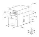
図1に示される画像記録装置100(液体供給システムの一例)は、インクジェット記録方式でロール体37(図2参照)をなすシートSに画像を記録する。[Exterior configuration of image recording device 100]
The image recording apparatus 100 (an example of a liquid supply system) shown in FIG. 1 records an image on a sheet S forming a roll body 37 (see FIG. 2) using an inkjet recording method.
図1に示されるように、画像記録装置100は、筐体30を備える。筐体30は、上筐体31及び下筐体32を備える。上筐体31及び下筐体32は、全体として概ね直方体形状であって、卓上に載置可能な大きさである。すなわち、画像記録装置100は、卓上に載置されて使用されるのに適している。もちろん、画像記録装置100は、床面やラックに載置されて使用されてもよい。なお、筐体30の内部には、各部材を支持するためのフレームが適宜設けられてもよい。 As shown in FIG. 1, the
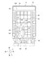
図2に示されるように、上筐体31は、下筐体32によって回動可能に支持されている。上筐体31は、後下端部に設けられ且つ左右方向9に延びる回動軸15周りに、図2に示される閉位置と、開位置とに回動可能である。なお、上筐体31が回動する構成は、回動軸15によるものに限らず、例えば蝶番などによって回動してもよい。 As shown in FIG. 2, the
図2に示されるように、上筐体31が閉位置のとき、上筐体31の内部空間31Aと下筐体32の内部空間32Aとが、外部に対して遮蔽される。上筐体31が開位置のとき、上筐体31の内部空間31Aと下筐体32の内部空間32Aとが、外部に対して露出される。 As shown in FIG. 2, when the
図1に示されるように、下筐体32の前面32Fには、左右方向9に長いスリット状の排出口33が形成されている。排出口33からは、画像記録済みのシートS(図2参照)が排出される。 As shown in FIG. 1, a slit-shaped
上筐体31の前面31Fには、操作パネル44が設けられている。ユーザは、操作パネル44に、画像記録装置100を動作させたり各種設定を確定したりするための入力を行う。 An
図1に示されるように、下筐体32の前面32Fには、前カバー39が位置する。前カバー39は、下端付近において左右方向9に沿って延びる回動軸(不図示)周りに、上端側が前方へ倒れるように開くことができる。前カバー39の開閉により、下筐体32の内部空間32Aに位置するカートリッジ装着部110等(図2参照)が露出されたり遮蔽されたりする。 As shown in FIG. 1, a
[画像記録装置100の外観構成]
図1に示される画像記録装置100は、インクジェット記録方式でロール体37(図2参照)をなすシートSに画像を記録する。[Exterior configuration of image recording device 100]
The
図1に示されるように、画像記録装置100は、筐体30を備える。筐体30は、上筐体31及び下筐体32を備える。上筐体31及び下筐体32は、全体として概ね直方体形状であって、卓上に載置可能な大きさである。すなわち、画像記録装置100は、卓上に載置されて使用されるのに適している。もちろん、画像記録装置100は、床面やラックに載置されて使用されてもよい。なお、筐体30の内部には、各部材を支持するためのフレームが適宜設けられてもよい。 As shown in FIG. 1, the
図2に示されるように、上筐体31は、下筐体32によって回動可能に支持されている。上筐体31は、後下端部に設けられ且つ左右方向9に延びる回動軸15周りに、図2に示される閉位置と、開位置とに回動可能である。なお、上筐体31が回動する構成は、回動軸15によるものに限らず、例えば蝶番などによって回動してもよい。 As shown in FIG. 2, the
図2に示されるように、上筐体31が閉位置のとき、上筐体31の内部空間31Aと下筐体32の内部空間32Aとが、外部に対して遮蔽される。上筐体31が開位置のとき、上筐体31の内部空間31Aと下筐体32の内部空間32Aとが、外部に対して露出される。 As shown in FIG. 2, when the
図1に示されるように、下筐体32の前面32Fには、左右方向9に長いスリット状の排出口33が形成されている。排出口33からは、画像記録済みのシートS(図2参照)が排出される。 As shown in FIG. 1, a slit-shaped
上筐体31の前面31Fには、操作パネル44が設けられている。ユーザは、操作パネル44に、画像記録装置100を動作させたり各種設定を確定したりするための入力を行う。 An
図1に示されるように、下筐体32の前面32Fには、前カバー39が位置する。前カバー39は、下端付近において左右方向9に沿って延びる回動軸(不図示)周りに、上端側が前方へ倒れるように開くことができる。前カバー39の開閉により、下筐体32の内部空間32Aに位置するカートリッジ装着部110等(図2参照)が露出されたり遮蔽されたりする。 As shown in FIG. 1, a
[画像記録装置100の内部構成]
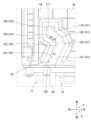
図2に示されるように、内部空間31A,32Aには、ホルダ35、テンショナ45、搬送ローラ対36、搬送ローラ対40、ヘッドユニット38、第1支持機構51、第2支持機構52、インクタンク34、洗浄液タンク76、及びメンテナンス機構60などが配置されている。[Internal configuration of image recording device 100]
As shown in FIG. 2, the
なお、内部空間32Aにおいて、ヘッドユニット38よりも搬送向き8Aの下流側には、図示しない定着ユニット、画像センサ、及びカッタ等が位置する。定着ユニットは、ヒータや紫外線照射装置であり、シートS上のインクをシートSに定着させる。定着ユニットがヒータの場合、インクは、熱によりシートS上に膜を形成する樹脂を含有する。定着ユニットが紫外線照射装置の場合、インクは、紫外線の照射により硬化する樹脂を含有する。画像センサは、シートS上に記録された画像を光学的に読み取って、読み取り結果を示す画像データをコントローラに出力する。カッタは、画像記録済みのシートSをカットする。 Note that in the
内部空間32Aには、隔壁41が設けられている。隔壁41は、内部空間32Aの後下部を仕切って、シート収容空間32Cを区画する。シート収容空間32Cは、隔壁41、下筐体32により包囲され、ヘッドユニット38などから隔離された空間である。 A
シート収容空間32Cには、ロール体37が収容される。ロール体37は、芯管と、長尺のシートSとを有している。シートSは、芯管の軸芯の周方向にロール状に芯管に巻回されている。シートSは、画像記録装置100が画像を記録可能な最小幅から最大幅までの幅をとり得る。すなわち、シート収容空間32Cには、幅が異なる複数種類のロール体37が収容可能である。なお、ロール体37は、芯管を有さず、シートSがホルダ35に装着可能にロール状に巻回されていてもよい。また、シート収容空間32Cには、ファンフォールド紙が収容可能であってもよい。図1に示されるように、下筐体32の右面32Rには、右カバー35Aが位置する。右カバー35Aの開閉により、シート収容空間32Cに位置するホルダ35等が露出したり遮蔽されたりする。 The
図2に示されるように、シート収容空間32Cは、後部において上方へ向かって開口している。詳細には、隔壁41と後面32Bとの間、すなわち、ロール体37の後端の上方に隙間42が形成されている。シートSは、搬送ローラ対36,40が回転することで、ロール体37の後端から上方に引き出され隙間42を介してテンショナ45へと案内される。 As shown in FIG. 2, the
テンショナ45は、内部空間32Aの後部において隔壁41よりも上方に位置する。テンショナ45は、下筐体32の外側を向いている外周面45Aを有している。外周面45Aは、左右方向9においてシートの最大幅以上の大きさであり、通紙中心(シートSの左右方向9における中心)に対して互いに対称な形状を有している。外周面45Aの上端は、上下方向7において搬送ローラ対36のニップ位置と概ね同じ上下位置にある。
外周面45Aには、ロール体37から引き出されたシートSが掛けられ当接する。シートSは、外周面45Aに沿って前方に湾曲して、搬送向き8Aに延びて搬送ローラ対36に案内される。搬送向き8Aは、前後方向8に沿う前向きである。テンショナ45は、周知の手法により、シートSにテンションを与える。 The sheet S pulled out from the
テンショナ45の前方には、搬送ローラ対36が位置する。搬送ローラ対36は、搬送ローラ36Aとピンチローラ36Bとを有する。搬送ローラ36A、及びピンチローラ36Bは、外周面45Aの上端と概ね同じ上下位置で当接する。 A conveying
搬送ローラ対36の前方には、搬送ローラ対40が位置する。搬送ローラ対40は、搬送ローラ40Aとピンチローラ40Bとを有する。搬送ローラ40A、及びピンチローラ40Bは、外周面45Aの上端と概ね同じ上下位置で当接する。 A
搬送ローラ36A,40Aは、不図示のモータから駆動力が伝達されて回転する。搬送ローラ対36は、テンショナ45から搬送向き8Aに延びるシートSをニップしつつ回転することにより、搬送面43Aに沿う搬送向き8Aに送り出す。搬送ローラ対40は、搬送ローラ対36から送り出されたシートSをニップしつつ回転することにより搬送向き8Aに送り出す。また、搬送ローラ対36,40の回転により、シートSは、シート収容空間32Cから隙間42を通ってテンショナ45に向けて引き出される。 The
図2に示されるように、内部空間32Aには、外周面45Aの上端から排出口33に至る搬送路43が形成されている。搬送路43は、搬送向き8Aに沿ってほぼ直線的に延びており、シートSが通過可能な空間である。詳細には、搬送路43は、搬送向き8A及び左右方向9に拡がり且つ搬送向き8Aに長い搬送面43Aに沿っている。なお、図2では、搬送面43Aは、搬送路43を示す二点鎖線で示されている。搬送路43は、上下方向7に離れて位置するガイド部材(不図示)や、ヘッドユニット38、搬送ベルト101などによって区画されている。 As shown in FIG. 2, a
ヘッドユニット38は、搬送路43の上方において搬送ローラ対36よりも搬送向き8Aの下流側に位置する。ヘッドユニット38は、複数のノズル38Aを有するヘッドモジュール49を有する。複数のノズル38Aから、インクが搬送ベルト101に支持されたシートSへ向かって下方へ吐出される。これにより、シートSに画像が記録される。 The
第1支持機構51は、搬送路43の下方において搬送ローラ対36よりも搬送向き8Aの下流に位置する。第1支持機構51は、ヘッドユニット38の下方に、ヘッドユニット38と対向している。第1支持機構51は、搬送ベルト101と支持部104を有する。搬送ベルト101は、搬送ローラ対36によって搬送向き8Aに搬送されてヘッドユニット38の直下に位置するシートSを支持する。搬送ベルト101は、支持しているシートSを搬送向き8Aに搬送する。支持部104は、メンテナンス機構60を支持可能である。 The
第2支持機構52は、搬送ローラ対40の下方に位置しており、下筐体32に支持されることによって下筐体32の内部に固定されている。第2支持機構52は、メンテナンス機構60を支持可能である。 The
インクタンク34は、インクを貯留している。インクは、顔料などを含む液体である。インクは、顔料を均一に分散させるに適した粘度を有している。顔料は、インクの色となるものである。インクタンク34から不図示のチューブを通じてインクがヘッドユニット38に供給される。 The
洗浄液タンク76は、洗浄液を貯留している。洗浄液は、ヘッドユニット38のノズル38Aを洗浄するときに使用される。洗浄液タンク76は、ノズル38Aを洗浄した洗浄液を廃液として貯留するためにも使用される。洗浄液タンク76の詳細な構成について後述される。 The cleaning
カートリッジ装着部110は、下筐体32の前端および下端付近に位置しており、前方を向いて開口する箱形状である。カートリッジ装着部110には、後向きへ洗浄液タンク76が挿入される。カートリッジ装着部110の後向きの終面111には、前方へ向かって延びる供給ニードル112が位置する。供給ニードル112の前端は開口しており、後端は流路113に連結されている。流路113は、後述される供給チューブ175と連結している。流路113には流路113を開閉するバルブ116が位置する。カートリッジ装着部110の後向きの終面111には、前方へ向かって延びる排出ニードル114が位置する。排出ニードル114の前端は開口しており、後端は流路115に連結されている。流路115は、後述される廃液チューブ178と連結している。流路113には吸引ポンプ117が位置する。 The
なお、インクタンク34に対してもカートリッジ装着部110と同様の装着ケースが設けられているが、ここでは詳細な説明が省略される。インクタンク34は、インクを貯留している。インクは、顔料などを含む液体である。インクは、顔料を均一に分散させるに適した粘度を有している。顔料は、インクの色となるものである。インクタンク34は、インクが消費されるとカートリッジ装着部から取り外され、インクを貯留している新しいインクタンク34と交換される。 Note that a mounting case similar to that of the
メンテナンス機構60は、ヘッドユニット38のメンテナンスを行うためのものである。メンテナンス機構60は、移動可能に構成されており、ヘッドユニット38のメンテナンスが行われるときにヘッドユニット38の直下に移動される(図5参照)。 The
ヘッドユニット38のメンテナンスは、パージ処理、浸漬処理、及びワイピング処理などである。パージ処理は、図5に示されるように、メンテナンス機構60のキャップ62によってノズル38Aを被覆した上で吸引ポンプによってノズル38Aからインクを吸引する処理である。浸漬処理は、キャップ62がノズル38Aを被覆した状態でキャップ62に供給された洗浄液にノズル38Aを浸漬する処理である。ワイピング処理は、メンテナンス機構60のスポンジワイパ64及びゴムワイパ63によってヘッドユニット38のヘッドモジュール49の下面50を払拭する処理である。 Maintenance of the
[メンテナンス機構60]
図3に示されるように、メンテナンス機構60は、支持体61、スポンジワイパ64、ゴムワイパ63、及びキャップ62を備えている。なお、以下のメンテナンス機構60の説明では、メンテナンス機構60が第2支持機構52によって支持されているとする。[Maintenance mechanism 60]
As shown in FIG. 3, the
[支持体61]
支持体61は、底台61Aと、底台61Aに載置される本体61Bと、スポンジワイパ64及びゴムワイパ63を本体61Bに保持するワイパホルダ61Cと、を有する。底台61Aは、上方が開口された箱型形状を有する。[Support 61]
The
底台61Aの下面121は、第1支持機構51の上面に上方から当接可能である。これにより、メンテナンス機構60は、第1支持機構51によって支持可能である。また、下面121は、第2支持機構52の上面に上方から当接可能である。これにより、メンテナンス機構60は、第2支持機構52によって支持可能である。 The
底台61Aは、ラック154(図2参照)を備えている。ラック154は、底台61Aの下面121の右端に形成されている。ラック154は、ギヤ105と噛合可能である。ラック154とギヤ105とが噛合した状態でギヤ105が回転することによって、メンテナンス機構60は、第1支持機構51に対して前後方向8に沿って摺動する。 The bottom stand 61A includes a rack 154 (see FIG. 2). The
ラック154は、ギヤ118およびギヤ119と噛合可能である。ラック154とギヤ118及びギヤ119の少なくとも一方とが噛合した状態でギヤ105が回転することによって、メンテナンス機構60は、第2支持機構52に対して前後方向8に沿って摺動する。 Rack 154 can mesh with
これにより、メンテナンス機構60は、図2に示される待機位置、図5に示されるメンテナンス位置に移動可能である。メンテナンス位置及びワイピング位置のメンテナンス機構60は、ヘッドユニット38のヘッドモジュール49の下面50と上下方向7に対向している。 Thereby, the
本体61Bは、上方が開放された略箱形形状である。本体61Bは、底台61Aよりも小さい。本体61Bは、底台61Aに載置された状態で底台61Aに固定されている。本体61Bには、洗浄液タンク76に貯留される洗浄液が流通可能な流路が形成されている。流路には、供給チューブ175を通じて洗浄液タンク76から洗浄液が供給され、廃液チューブ178を通じて流路から洗浄液タンク76へ洗浄液が排出される。流路を通じてスポンジワイパ64へ洗浄液が供給される。 The
ワイパホルダ61Cは、3つのスポンジワイパ64A,64B,64C、3つのゴムワイパ63A,63B,63C、および3つのキャップ62A,62B,62Cをそれぞれ保持する。スポンジワイパ64は、液体を吸収して保持する多孔質体であるスポンジによって形成されている。本実施形態では、スポンジワイパ64は、3つ(64A、64B、64C)設けられている。なお、スポンジワイパ64の数は、3つに限らず上述したヘッドユニット38のヘッドモジュール49の数に合わせて設定される。以下、3つのスポンジワイパ64A,64B,64Cを総称して、スポンジワイパ64とも称する。スポンジワイパ64は、左右方向9の長さが傾斜方向6及び上下方向7の長さよりも長い直方体状である。スポンジワイパ64の上下方向7の長さは、傾斜方向6の長さよりも長い。スポンジワイパ64の下部は本体61Bの流路内に進入している。 The
ゴムワイパ63は、液体を吸収して保持しない弾性体であるゴムによって形成されている。本実施形態では、ゴムワイパ63は、3つ(63A、63B、63C)が設けられている。なお、ゴムワイパ63の数は、3つに限らず上述したヘッドユニット38のヘッドモジュール49の数に合わせて設定される。以下、3つのゴムワイパ63A、63B、63Cを総称して、ゴムワイパ63とも称する。 The
ゴムワイパ63は、上下方向7及び左右方向9に拡がる平板状に形成されている。ゴムワイパ63の傾斜方向6の長さは、スポンジワイパ64の傾斜方向6の長さよりも短い。これにより、ゴムワイパ63は、ワイピング処理時においてヘッドモジュール49の下面50に当接したときに、屈曲しやすくなっている。ゴムワイパ63の左右方向9の長さは、スポンジワイパ64の左右方向9の長さよりも僅かに長い。 The
キャップ62は、ゴムやシリコンなどの弾性体で構成されている。キャップ62は、上方が開放された箱形形状である。本実施形態では、キャップ62は、3つのキャップ62A,62B,62Cで構成されている。なお、キャップ62の数は、3つに限らず上述したヘッドユニット38のヘッドモジュール49の数に合わせて設定される。以下、3つのキャップ62A,62B,62Cを総称して、キャップ62とも称する。 The
キャップ62の底板69には、洗浄液がキャップ62に流入する流入口(図示省略)と洗浄液がキャップ62から流出する流出口69Aとが形成されている。流入口には、供給チューブ175の一端が接続されている。供給チューブ175の他端は、洗浄液タンク76に接続されている。流出口には、廃液チューブ178の一端が接続されている。廃液チューブ178の他端は、洗浄液タンク76に接続されている。吸引ポンプ117が駆動されることにより、キャップ62の流出口69Aから洗浄液タンク76へ液体が吸引される。 The
[メンテナンス機構60の移動]
メンテナンス機構60は、第2支持機構52に支持された状態で第2支持機構52に対して摺動することによって傾斜方向6に沿って待機位置とクリーニング終了位置とに移動可能である。[Movement of maintenance mechanism 60]
The
図2に示されるように、待機位置のメンテナンス機構60は、第1支持機構51の回動先端51Aよりも前方(搬送向き8Aの下流)に位置している。換言すると、待機位置のメンテナンス機構60は、第1支持機構51の回動先端51Aに対して第1支持機構51の軸109Aの反対に位置する。待機位置のメンテナンス機構60は、第2支持機構52に支持されている。このとき、ラック154は、ギヤ118,119双方と噛合している。 As shown in FIG. 2, the
メンテナンス機構60は、第2支持機構52と第2回動位置の第1支持機構51との間で受け渡しされることによって待機位置とメンテナンス位置とに移動可能である。待機位置は、メンテナンス位置から退避した位置である。 The
不図示のモータが駆動されて、図4に示されるように第1支持機構51が第2回動位置となる。この状態でモータが駆動されて、ギヤ120が図4において反時計回りに回転すると、ギヤ118,119が図4において時計回りに回転する。これにより、待機位置のメンテナンス機構60は、後傾斜向き4へ移動する。 A motor (not shown) is driven, and the
メンテナンス機構60が第1支持機構51のみに支持された状態において、モータが駆動されることによって、第1支持機構51が第2回動位置から第1回動位置へ回動される。これにより、図5に示されるように、メンテナンス機構60は、メンテナンス位置に位置する。メンテナンス位置のメンテナンス機構60は、ヘッドユニット38と第1回動位置の第1支持機構51との間に位置している。なお、メンテナンス機構60がメンテナンス位置から待機位置へ移動するときは、上記と逆の動作が実行される。 When the
メンテナンス機構60は、第1回動位置の第1支持機構51に支持された状態で第1支持機構51に対して前後方向8に移動することによってメンテナンス位置とワイピング位置とに移動可能である。ワイピング位置は、メンテナンス位置よりも前方(待機位置側)の位置である。つまり、第1支持機構51は、メンテナンス位置、ワイピング位置、及び前記の両位置の間に位置するメンテナンス機構60を支持可能である。 The
[画像記録処理]
以下に、シートSに画像が記録されるときの処理(画像記録処理)が説明される。[Image recording processing]
Below, the process when an image is recorded on the sheet S (image recording process) will be explained.
画像記録処理が実行されていないとき、画像記録装置100は待機状態である。待機状態のとき、図5に示されるように、ヘッドユニット38は被キャッピング位置に位置しており、第1支持機構51はメンテナンス機構60を支持した状態で第1回動位置に位置しており、メンテナンス機構60はメンテナンス位置に位置している。このとき、キャップ62は、ノズル38Aを覆っている。 When image recording processing is not being executed, the
操作パネル44や、画像記録装置100とLANなどによって接続された情報処理装置などの外部から、シートSに画像を記録する旨の命令を画像記録装置100のコントローラが受け取ると、メンテナンス機構60がメンテナンス位置から待機位置へ移動される。そして、第1支持機構51が第2回動位置から第1回動位置へ回動される。 When the controller of the
次に、シートSの搬送が開始して、シートSがヘッドユニット38の直下に位置する状態でノズル38Aからインクを吐出する。これによりシートSに画像が記録される。 Next, conveyance of the sheet S is started, and ink is ejected from the
[パージ処理]
以下に、ノズル38Aからインクを吸引するパージ処理が説明される。[Purge processing]
A purge process for sucking ink from the
画像記録処理が実行されていないとき、画像記録装置100が待機状態である。待機状態のとき、図5に示されるように、第1支持機構51はメンテナンス機構60を支持した状態で第1回動位置に位置しており、メンテナンス機構60はメンテナンス位置に位置している。このとき、キャップ62は、ノズル38Aを覆っている。 When image recording processing is not being executed, the
パージ処理は、例えば待機状態において所定タイミングでまたは外部からの命令を受け取ったときに実行される。以下では、画像記録装置100が待機状態のときに、コントローラがパージ処理を実行する旨の命令を受け取ったときの処理が説明される。 The purge process is executed, for example, at a predetermined timing in a standby state or when an external command is received. In the following, a process will be described when the controller receives a command to execute a purge process while the
パージ処理において、吸引ポンプ117が駆動されると、ノズル38A内のインクが吸引されて、キャップ62とヘッドモジュール49の下面50とによって形成された空間から廃液チューブ178を通ってインクが洗浄液タンク76に排出される。これにより、インクの固化によるノズル38Aの目詰まりを防止している。 In the purge process, when the
[ワイピング処理]
パージ処理の後、スポンジワイパ64及びゴムワイパ63がヘッドユニット38のヘッドモジュール49の下面50を払拭するワイピング処理が実行される。ヘッドユニット38が上方へ移動されることによって、キャップ62がヘッドモジュール49の下面50から離間する。[Wiping process]
After the purge process, a wiping process is performed in which the
次いで、不図示の吸引ポンプが駆動されて、洗浄液タンク76から供給チューブ175を通して洗浄液がスポンジワイパ64に供給される。 Next, a suction pump (not shown) is driven, and the cleaning liquid is supplied from the cleaning
次に、メンテナンス機構60がメンテナンス位置からワイピング位置へ移動される。メンテナンス機構60がメンテナンス位置からワイピング位置へ移動する過程において、スポンジワイパ64及びゴムワイパ63の先端部(上端部)がヘッドモジュール49の下面50に当接しつつ下面50に対して摺動する。これにより、各ヘッドモジュール49A,49B,49Cの下面50が払拭される。その結果、下面50に付着した液体や異物などが取り除かれる。 Next, the
[キャップ処理]
キャップ処理において、吸引ポンプ117が駆動されることにより、洗浄液タンク76から供給チューブ175を通してキャップ62A,62B,62Cに洗浄液が供給される。その後、ヘッドユニット38が下方へ移動されることによって、キャップ62がヘッドモジュール49の下面50に当接する。これにより、ノズル38Aは、洗浄液が存在する空間におかれるので、ノズル38Aにおいてインクが乾燥し難い。ヘッドユニット38が下方へ移動されることによって、キャップ62がヘッドモジュール49の下面50から離間する。このとき、キャップ62A,62B,62C内の洗浄液は洗浄液タンク76へ排出される。[Cap processing]
In the capping process, by driving the
[カートリッジ装着部110]
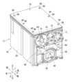
図6に示されるように、カートリッジ装着部110は、前後方向8の前向き(脱抜向きの一例)に開口するケース130を有する。ケース130は、内部空間を左右方向9において仕切る仕切り板131を有する。仕切り板131によって仕切られたケース130の内部空間のうち、右側に洗浄液タンク76が挿入され、左側にインクタンク34が挿入される。以下、洗浄液タンク76が挿入される右側の内部空間の構成について説明される。[Cartridge mounting section 110]
As shown in FIG. 6, the
ケース130の終面111には、供給ニードル112および排出ニードル114(図2参照)が前方へ向かって延びている。なお、排出ニードル114は終面111の上側に位置しており、図6においては現れていない。供給ニードル112の上方には、2つの位置決めボス132が左右方向9に離れて位置している。位置決めボス132は前方へ向かって突出する円柱形状である。 On the
ケース130の底面133より前方には、案内面134が位置する。案内面134は、底面133の前端から前方かつ下方へ延びている。案内面134により、ケース130に挿入される洗浄液タンク76が底面133へ案内される。 A
ケース130の底面133には、前後方向8に沿って延びる2つのガイドリブ143が左右方向9に離れて位置する。ガイドリブ143は底面133から上方へ突出している。2つのガイドリブ143の間隔は、洗浄液タンク76の左右方向9の寸法よりも若干大きい。2つのガイドリブ143の間において、底面133上に位置する洗浄液タンク76の移動方向が前後方向8へ案内される。 On the
ケース130の底面133の終面111付近には、左右方向9へ延びる貫通孔135が位置する。貫通孔135を底面133においてケース130を上下方向7に貫通している。貫通孔135には、ラッチ136が位置する。ラッチ136は、貫通孔135において左右方向9へ移動可能である。 A through
図6に示されるように、ラッチ136は上下方向7を軸線とする円柱形状である。図7に示されるように、ラッチ136は、ケース130の下面に取り付けられた支持板137および回動部材138によって、ケース130に連結されている。支持板137はケース130の下面に固定されている。なお、図7では、ケース130が省略されている。支持板137は、上下方向7に延びる軸139を有する。軸139に回動部材138が所定範囲で回動可能に連結されている。なお、回動部材138の回動範囲は、支持板137において下方へ折り曲げられたストッパ142により規制されている。回動部材138の回動先端側には、上下方向7に延びる軸140が連結されている。軸140に、ラッチ136が回転自在に連結されている。支持板137と回動部材138との間にはねじりコイルバネ141(弾性部材の一例)が設けられている。ねじりコイルバネ141は、図7において回動部材138を時計周りに付勢している。回動部材138の回動範囲において、ねじりコイルバネ141は、回動部材を概ね左右方向9の左向きに付勢している。 As shown in FIG. 6, the
なお、詳細な説明は省略されるが、ケース130の内部空間のうち左側の内部空間にも、同様に、インクニードル121、ガイドリブ143、位置決めボス132、案内面134、貫通孔135、およびラッチ136が位置する。ケース130の内部空間の右側に位置するインクニードル121、ガイドリブ143、位置決めボス132、案内面134、貫通孔135、およびラッチ136は、インクタンク34に対応するものである。 Although detailed description is omitted, the left internal space of the
[洗浄液タンク76]
洗浄液タンク76(液体カートリッジの一例)は、洗浄液を貯留している。洗浄液は、有機溶剤や界面活性剤、水などを含む液体である。洗浄液タンク76は、廃液を貯留する空間でもある。洗浄液タンク76において、洗浄液はパウチ90に貯留されており、廃液はパウチ90の外側においてケース本体77(筐体の一例)に貯留される。洗浄液タンク76は、洗浄液が消費されたり、廃液で満たされたりすると、カートリッジ装着部110から取り外されて、新しい洗浄液タンク76と交換される。[Cleaning liquid tank 76]
The cleaning liquid tank 76 (an example of a liquid cartridge) stores cleaning liquid. The cleaning liquid is a liquid containing an organic solvent, a surfactant, water, and the like. The cleaning
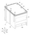
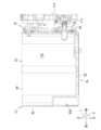
図8から図12に示されるように、洗浄液タンク76は、ケース本体77と、カバー78と、フィルム79と、パウチ90とを有する。なお、以下では、洗浄液タンク76の上下方向7、前後方向8、左右方向9は、洗浄液タンク76がカートリッジ装着部110に装着された状態において、筐体30の各方向に合わせて説明がされている。ケース本体77、カバー78、およびフィルム79がケースの一例である。 As shown in FIGS. 8 to 12, the cleaning
ケース本体77は、上向きの開口81を有する箱形状である。ケース本体77は、下壁82、前壁83、後壁84、左壁85、および右壁86を有する。下壁82は、上下方向7から視て前後方向8に長い長方形である。前壁83は、下壁82の前端から上方へ延びている。前壁83には、後方へ凹む凹部83Aが形成されている。凹部83Aは、下壁82にも開口している。凹部83Aは、ユーザがケース本体77を引き出すときの持ち手となる。後壁84は、下壁82の後端から上方へ延びている。後壁84の外面が装着向きの前面となる。 The
左壁85は、下壁82の左端から上方へ延びており、前壁83と後壁84とを繋いでいる。右壁86は、下壁82の右端から上方へ延びており、前壁83と後壁84とを繋いでいる。 The
図12に示されるように、開口81は、前壁83の上端、後壁84の上端、左壁85の上端、および右壁86の上端により区画されている。開口81により、ケース本体77の内部空間が外部に露出される。ケース本体77の内部空間は、貯留室77Aである。開口81を区画する前壁83の上端、後壁84の上端、左壁85の上端、および右壁86の上端には、フィルム79を溶着するための溶着面87が位置する。溶着面87は、開口81を囲む矩形をなしている。図11に示されるように、溶着面87にフィルム79が溶着されることにより、開口81が液密に封止される。 As shown in FIG. 12, the
溶着面87の外側には、前後方向8に並ぶ3つのネジ穴88が左右方向9に分かれて2列に位置する。換言すれば、左壁85の上端に3つのネジ穴88が前後方向8に並んでおり、右壁86の上端に3つのネジ穴88が前後方向8に並んでいる。 On the outside of the
ケース本体77に溶着されたフィルム79は、カバー78により覆われる。カバー78は、前壁83の上端、後壁84の上端、左壁85の上端、および右壁86の上端に当接する矩形の平板形状である。カバー78には、前後方向8に並ぶ3つの貫通孔89が左右方向9に分かれて2列に位置する。貫通孔89の配置は、ネジ穴88の配置に対応している。カバー78がフィルム79を覆った状態において、貫通孔89およびネジ穴88にネジ99が挿通されて螺合されることにより、ケース本体77にカバー78が固定される。 The
ケース本体77の後壁84には、3つの開口が形成されており、各開口に、スパウト70,71,92が嵌め込まれている。スパウト70は、前後方向8に延びる大気連通孔72を有する。大気連通孔72は、スパウト70において前後方向8の両側に向かって開口している。スパウト70が後壁84の開口に嵌め込まれることにより、大気連通孔72は、貯留室77Aと外部とを連通する。 Three openings are formed in the
スパウト71は、前後方向8に延びる流入孔73を有する。流入孔73は、スパウト71において前後方向8の両側に向かって開口している。スパウト71が後壁84の開口に嵌め込まれることにより、流入孔73は、貯留室77Aと外部とを連通する。流入孔73には、排出ニードル114が挿入される。なお、流入孔73は、バルブにより開閉可能であってもよい。その場合、排出ニードル114が流入孔73に挿入されることにより、バルブが閉状態から開状態となる。 The
スパウト92は、前後方向8に延びる供給孔93(供給口の一例)を有する。スパウト92は、後述するパウチ90を構成する部品である。供給孔93は、スパウト92において前後方向8の両側に向かって開口している。スパウト92が後壁84の開口に嵌め込まれることにより、供給孔93は、パウチ90の袋91の内部空間と外部とを連通する。供給孔93には、供給ニードル112が挿入される。なお、供給孔93は、バルブにより開閉可能であってもよい。その場合、供給ニードル112が供給孔93に挿入されることにより、バルブが閉状態から開状態となる。 The
図13に示されるように、後壁84の開口において、スパウト92と後壁84の開口周縁との間には、Oリング74が配置されて液密に封止されている。図示はされていないが、スパウト70,71と後壁84の開口周縁との間にも、Oリング74が配置されて液密に封止されている。 As shown in FIG. 13, an O-
図8および図10に示されるように、後壁84には、インジケータ75が位置する。インジケータ75は、透光性を有する部材からなる中空の箱形状である。インジケータ75は、上下方向7に細長な外形である。インジケータ75は、後壁84の開口84Aを通じて外部に露出されている。インジケータ75の内部空間は貯留室77Aと連通している。貯留室77Aに貯留された廃液の液面がインジケータ75の位置まで上昇すると、インジケータ75の内部空間に廃液が進入して、貯留室77Aと同じ高さの液面が形成される。インジケータ75が透光性を有するので、インジケータ75の内部空間に形成された廃液の液面は、外部から視認可能である。インジケータ75は、例えば、カートリッジ装着部110に光学センサが設けられることにより、インジケータ75の所定の位置に廃液の液面が上昇したかを判定するために用いられてもよい。なお、インジケータ75と開口84Aの周縁との間は、パッキンなどにより液密に封止されている。 As shown in FIGS. 8 and 10, an
図8および図10に示されるように、後壁84において上下方向7の中央付近には、2つの円筒96が左右方向9に離れて位置する。2つの円筒96の距離は、ケース130の2つの位置決めボス132の距離と同等である。円筒96は、後向きへ開口しており、円筒96の内部空間には位置決めボス132が進入可能である。 As shown in FIGS. 8 and 10, two
ケース本体77の貯留室77Aには、洗浄液を貯留するパウチ90が収容される。図14に示されるように、パウチ90は、可撓性の袋91とスパウト92とを有する。図8および図10に示されるように、スパウト92は、ケース本体77の後壁84の開口に嵌め込まれており、袋91が貯留室77Aに位置する。 A
図14に示されるように、袋91は、合成樹脂製のシートが溶着されることによって、立方体に膨らむものである。スパウト92は、袋91の下端付近に位置する。スパウト92は、合成樹脂製の部材である。スパウト92は、袋91に形成された貫通孔の周囲に溶着されている。 As shown in FIG. 14, the
袋91に充填されている洗浄液は、メンテナンス機構60に供給されて、最終的には廃液として貯留室77Aに排出される。貯留室77Aに排出される廃液には、ヘッドモジュール49から排出されたインクも含まれるので、廃液に含まれるインク量を考慮すると、袋91に充填される洗浄液の量は、貯留室77Aの容積よりも若干少ないことが好ましい。 The cleaning liquid filled in the
図15に示されるように、下壁82の外面である下面94には上方へ凹む溝95が位置する。溝95は、前壁83の外面である前面において前方へ開口する進入口160を有する。溝95は、進入口160から左右方向9へ向かいつつ前後方向8の前向きへ延びている。 As shown in FIG. 15, a
溝95は、左右方向9において対向する右面161および左面162を有する。上下方向7に沿って拡がる右面161および左面162によって溝95が区画されている。右面161と左面162との間は下方へ向かって開口している。 The
左面162は、第1面163、第2面164、第3面165、および第4面166を有する。進入口160から前向きへ、第1面163、第3面165、第2面164、第4面166の順に並んでそれぞれが繋がっている。 The
第1面163は、法線ベクトルが前後方向8の後向き(装着向きの一例)且つ左右方向9の右向き(一方向きの一例)へ向いている。第2面164は、第1面163より前後方向8の前向き(脱抜向きの一例)に位置しており、法線ベクトルが前後方向8の前向き且つ左右方向9の右向きへ向いている。 The normal vector of the
第3面165は、第1面163と第2面164とを繋いでおり、法線ベクトルが前後方向8の前向き且つ左右方向9の右向きへ向いている。上下方向7から視て、第3面165の前後方向8に対する傾斜角度A3は、第1面163の前後方向8に対する傾斜角度A1および第2面164の前後方向8に対する傾斜角度A2のいずれよりも小さい(A3<A1,A3<A1)。第4面166は、第2面164の前端から前後方向8に沿って後向きへ延びている。第4面166の法線ベクトルは、左右方向9の右向きである。 The
右面161は、第5面167、第6面168、第7面169、および第8面170を有する。進入口160から前向きへ、第5面167、第7面169、第6面168、第8面170の順に並んでそれぞれが繋がっている。 The
第5面167は、左右方向9において第1面163と対向して平行に延びている。第5面167は、法線ベクトルが前後方向8の前向き且つ左右方向9の左向きへ向いている。左右方向9において第6面168は、第2面164と対向して平行に延びている。第6面168は、第5面167より前後方向8の前向きに位置しており、法線ベクトルが前後方向8の後向き且つ左右方向9の左向きへ向いている。 The
第7面169は、左右方向9において第3面165と対向して平行に延びている。第7面169は、第5面167と第6面168とを繋いでおり、法線ベクトルが前後方向8の後向き且つ左右方向9の左向きへ向いている。第8面170は、第7面169の前端から前後方向8に沿って前向きへ延びている。第8面170の法線ベクトルは、左右方向9の左向きである。 The
第4面166の前端と第8面170の前端とは終面171によって繋がれている。終面171の法線ベクトルは、前後方向8の後向きである。 The front end of the
[カートリッジ装着部110への洗浄液カートリッジ76の装着]
カートリッジ装着部110のケース130に挿入される洗浄液カートリッジ76は、案内面134に案内されて、ケース130の底面133へ移動する。ケース130の底面133において、洗浄液タンク76は、2つのガイドリブ143により前後方向8に案内されて後向きへ進む。[Attachment of cleaning
The cleaning
図16に示されるように、ケース130の内部空間を後向きへ進む洗浄液タンク76において、進入口160からラッチ136が溝95へ進入する。ラッチ136はねじりコイルバネ141により左向きへ付勢されているので、溝95に進入したラッチ136は、左面162の第1面163に当接しつつ軸140周りに回転しながら第3面165へ向かう。第1面163により、ラッチ136はねじりコイルバネ141の付勢力に抗して左向きへ移動する。ラッチ136から第1面163へ伝わる反力が前後方向8の前向きの成分を有するので、洗浄液タンク76を後向きへ移動するときの抵抗として、洗浄液タンク76を挿入するユーザに伝わる。 As shown in FIG. 16, the
図16に示されるように、ラッチ136が第1面163の前端付近にあるとき、図17に示されるように、ケース130の供給ニードル112は、洗浄液タンク76の供給孔93に進入していない。図には現れていないが、ケース130の排出ニードル114は、洗浄液タンク76の流入孔73に進入していない。図18に示されるように、ケース130の位置決めボス132は、洗浄液タンク76の円筒96の内部空間に進入する。これにより、洗浄液タンク76がケース130に対して上下方向7および左右方向9に位置決めされる。なお、図17および図18においては、洗浄液タンク76において、カバー78、フィルム79、袋91が省略されている。 When the
洗浄液タンク76がさらに後向きへ移動されることにより、ラッチ136は、第1面163から第3面165へ移動する。ラッチ136から第3面165へ伝わる反力は前後方向8の後向きの成分を有するので、洗浄液タンク76を後向きへ移動するときの抵抗が消失した感覚がユーザに伝わる。 As the cleaning
洗浄液タンク76がさらに後向きへ移動されることにより、ラッチ136は、第3面165から第2面164へ移動する。第2面164は、第3面165と同様に前向きである。また、第3面165の傾斜角度A3は、第2面164の傾斜角度A2より小さい。換言すれば、第2面の傾斜角度A2は、第3面165の傾斜角度A3よりも大きい。ラッチ136から第2面164へ伝わる反力は前後方向8の後向きの成分を有しており、後向きの成分の大きさは、第3面165において伝わる反力よりも大きいので、洗浄液タンク76を後向きへ移動するときの抵抗が消失し、さらに後向きへ引き込まれるような感覚がユーザに伝わる。 As the cleaning
図19に示されるように、ラッチ136が第2面164の前端付近にあるとき、図20に示されるように、ケース130の供給ニードル112は、洗浄液タンク76の供給孔93に進入する。図には現れていないが、ケース130の排出ニードル114は、洗浄液タンク76の流入孔73に進入する。図21に示されるように、ケース130の位置決めボス132は、洗浄液タンク76の円筒96の内部空間にさらに進入した状態となる。なお、図20および図21においては、洗浄液タンク76において、カバー78、フィルム79、袋91が省略されている。 When the
洗浄液タンク76がさらに後向きへ移動されることにより、ラッチ136は、第2面164から第4面166へ移動する。ラッチ136から第4面166へ伝わる反力は前後方向8の成分を有しないので、洗浄液タンク76を後向きへ引き込まれるような感覚が消失したようにユーザに伝わる。これにより、ユーザは、洗浄液タンク76の装着が完了した感覚を得る。 Further rearward movement of the cleaning
図22に示されるように、ラッチ136が第4面166にあるとき、図23に示されるように、ケース130の供給ニードル112は、洗浄液タンク76の供給孔93にさらに進入する。図24に示されるように、ケース130の位置決めボス132は、洗浄液タンク76の円筒96の内部空間にさらに進入した状態となる。これにより、洗浄液タンク76のパウチ90に貯留された洗浄液が、供給ニードル112、流路113、供給チューブ175を通じてメンテナンス機構60に供給される。また、メンテナンス機構60から流出する廃液が、廃液チューブ178、流路115、排出ニードル114を通じて洗浄液タンク76の貯留室77Aに排出される。なお、図には示されていないが、位置決めボス132が円筒96の内部空間の終面に当接することにより、ユーザは、洗浄液タンク76がさらに後向きに移動できない感覚を得る。なお、図23および図24においては、洗浄液タンク76において、カバー78、フィルム79、袋91が省略されている。 When the
[本実施形態の作用効果]
本実施形態によれば、洗浄液タンク76がカートリッジ装着部110に装着されるときに、ラッチ136が溝95に進入して第1面163および第2面164に沿って移動するので、洗浄液タンク76の装着が完了した位置をユーザに感覚的に示すことができる。[Actions and effects of this embodiment]
According to this embodiment, when the cleaning
また、溝95の第3面165により、ラッチ136が第1面163から第2面164へ緩やかに移動するので、ユーザに大きな衝撃が伝わることが抑制される。 Further, the
また、溝95の第4面166により、ラッチ136の反力として前後方向8に沿った成分が消失するので、装着が完了した位置に後向きに沿った範囲があることをユーザに感覚的に示すことができる。 In addition, the
また、溝95に進入するラッチ136が、第1面163と第5面167との間、および第2面164と第6面168との間を通過するので、洗浄液タンク76が装着される勢いが強くても、第1面163や第2面164に当接したラッチ136が第1面163や第2面164から左右方向9の右向きへ大きく離れることが抑制される。これにより、ユーザに円滑な感覚が伝わる。 Furthermore, since the
[変形例]
前述した実施形態では、ねじりコイルバネ141によりラッチ136が左右方向9の左向きに付勢されているが、ラッチ136は右向きに付勢されてもよい。その場合、溝95は、前後方向8に沿った対称軸に対して反転した形状であってもよい。[Modified example]
In the embodiment described above, the
また、位置決めボス132および円筒96は省略されてもよい。その場合、ラッチ136が溝95の終面171と当接することにより、ユーザは、洗浄液タンク76がさらに後向きに移動できない感覚を得るようにしてもよい。 Further, the
また、前述された実施形態では、洗浄液タンク76を例に説明がされているが、インクタンク34およびケース130においても同様の構成が採用されてもよい。図25に示されるように、インクタンク34の下面には上方へ凹む溝20が位置する。溝20は、溝95と同様の構成であり、溝20において溝95と同じ符号が示されている面は、溝95と同様の面である。これにより、インクタンク34の装着が完了した位置をユーザに感覚的に示すことができる。 Further, in the embodiment described above, the cleaning
また、洗浄液タンク76に貯留される液体は一例にすぎず、インクの他、装置が長期間に渡り使用されないときにヘッドや流路などに満たされる保管液などであってもよい。また、洗浄液タンク76のように廃液が貯留されることは必須の構成ではない。 Further, the liquid stored in the cleaning
76・・・洗浄液タンク(液体カートリッジ)
77・・・ケース本体(筐体)
93・・・供給孔(供給口)
95・・・溝
100・・・・画像記録装置(液体供給システム)
110・・・カートリッジ装着部
112・・・供給ニードル(ニードル)
130・・・ケース
134・・・案内面
136・・・ラッチ
141・・・ねじりコイルバネ(弾性部材)
160・・・進入口
161・・・右面
162・・・左面
163・・・第1面
164・・・第2面
165・・・第3面
166・・・第4面
167・・・第5面
168・・・第6面76...Cleaning liquid tank (liquid cartridge)
77...Case body (housing)
93... Supply hole (supply port)
95... Groove 100... Image recording device (liquid supply system)
110...
130...
160...
Claims (9)
Translated fromJapanese装着向きの前面を有しており、当該前面に貯留室と連通する供給口を有する筐体と、
上記筐体の下面において上方へ凹んだ溝と、を備えており、
上記溝は、
上記前面に開口する進入口と、
上記装着向きと交差する左右方向において上記溝を区画する右面および左面と、を有しており、
上記右面および上記左面の少なくとも一方は、上記装着向き且つ左右方向の一方向きへ向く第1面と、当該第1面より上記装着向きと反対の脱抜向きに位置しており、上記脱抜向き且つ左右方向の一方向きへ向く第2面と、を有しており、
上記溝に、上記カートリッジ装着部において左右方向に移動可能であって左右方向の他方向きへ付勢されたラッチが進入する液体カートリッジ。A liquid cartridge installed in a cartridge installation part,
A casing having a front face facing mounting and having a supply port communicating with a storage chamber on the front face;
a groove recessed upward on the lower surface of the casing;
The above groove is
an entrance opening on the front side;
It has a right surface and a left surface that partition the groove in the left and right direction intersecting the mounting direction,
At least one of the right surface and the left surface has a first surface facing the mounting direction and one of the left and right directions, and a first surface located in a removal direction opposite to the mounting direction from the first surface, and a first surface facing the removal direction opposite to the mounting direction. and a second surface facing in one direction in the left-right direction,
A liquid cartridge in which a latch that is movable in the left-right direction in the cartridge mounting portion and is biased in the other left-right direction enters into the groove.
上記液体カートリッジは、
装着向きの前面を有しており、当該前面に貯留室と連通する供給口を有する筐体と、
上記筐体の下面において上方へ凹んだ溝と、を備えており、
上記溝は、
上記前面に開口する進入口と、
上記装着向きと交差する左右方向において上記溝を区画する右面および左面と、を有しており、
上記右面および上記左面の少なくとも一方は、上記装着向き且つ左右方向の一方向きへ向く第1面と、当該第1面より上記装着向きと反対の脱抜向きに位置しており、上記脱抜向き且つ左右方向の一方向きへ向く第2面と、を有しており、
上記カートリッジ装着部は、
上記液体カートリッジが挿入される内部空間を有しており、上記脱抜向きへ開口するケースと、
上記ケースの内部空間において上記脱抜向きへ伸びるニードルと、
上記ケースの内部空間を区画する底面において、左右方向へ移動可能なラッチと、
上記ラッチを左右方向の他方向きへ付勢する弾性部材と、を有しており、
上記溝に、上記液体カートリッジが上記ケースに挿入されるときに、上記開口を通じて上記ラッチが進入し、
上記供給口に、上記液体カートリッジが上記ケースに挿入されるときに、上記ニードルが進入する液体供給システム。A liquid supply system comprising a liquid cartridge and a cartridge mounting part into which the liquid cartridge is moved in a mounting direction and mounted,
The above liquid cartridge is
A casing having a front face facing mounting and having a supply port communicating with a storage chamber on the front face;
a groove recessed upward on the lower surface of the casing;
The above groove is
an entrance opening on the front side;
It has a right surface and a left surface that partition the groove in the left and right direction intersecting the mounting direction,
At least one of the right surface and the left surface has a first surface facing the mounting direction and one of the left and right directions, and a first surface located in a removal direction opposite to the mounting direction from the first surface, and a first surface facing the removal direction opposite to the mounting direction. and a second surface facing in one direction in the left-right direction,
The above cartridge mounting part is
a case having an internal space into which the liquid cartridge is inserted and opening in the removal direction;
a needle extending in the withdrawal direction in the internal space of the case;
A latch movable in the left and right direction on the bottom surface that partitions the internal space of the case,
an elastic member that urges the latch in the other direction in the left-right direction;
the latch enters the groove through the opening when the liquid cartridge is inserted into the case;
A liquid supply system in which the needle enters the supply port when the liquid cartridge is inserted into the case.
9. The liquid supply system according to claim 5, wherein the case has a guide surface extending downward from the bottom surface toward the removal direction.
Priority Applications (2)
| Application Number | Priority Date | Filing Date | Title |
|---|---|---|---|
| JP2022057908AJP2023149374A (en) | 2022-03-31 | 2022-03-31 | Liquid cartridge and liquid supply system |
| US18/192,887US12377657B2 (en) | 2022-03-31 | 2023-03-30 | Liquid cartridge and liquid supply system |
Applications Claiming Priority (1)
| Application Number | Priority Date | Filing Date | Title |
|---|---|---|---|
| JP2022057908AJP2023149374A (en) | 2022-03-31 | 2022-03-31 | Liquid cartridge and liquid supply system |
Publications (1)
| Publication Number | Publication Date |
|---|---|
| JP2023149374Atrue JP2023149374A (en) | 2023-10-13 |
Family
ID=88195623
Family Applications (1)
| Application Number | Title | Priority Date | Filing Date |
|---|---|---|---|
| JP2022057908APendingJP2023149374A (en) | 2022-03-31 | 2022-03-31 | Liquid cartridge and liquid supply system |
Country Status (2)
| Country | Link |
|---|---|
| US (1) | US12377657B2 (en) |
| JP (1) | JP2023149374A (en) |
Families Citing this family (1)
| Publication number | Priority date | Publication date | Assignee | Title |
|---|---|---|---|---|
| CN118372556A (en)* | 2024-05-16 | 2024-07-23 | 珠海纳思达企业管理有限公司 | A consumables box |
Family Cites Families (3)
| Publication number | Priority date | Publication date | Assignee | Title |
|---|---|---|---|---|
| US8727516B2 (en)* | 2010-10-22 | 2014-05-20 | Hewlett-Packard Development Company, L.P. | Fluid cartridge |
| ES2752226T3 (en) | 2010-10-22 | 2020-04-03 | Hewlett Packard Development Co | Fluid cartridge |
| US8651642B2 (en)* | 2010-10-22 | 2014-02-18 | Hewlett-Packard Development Company, L.P. | Fluid cartridge |
- 2022
- 2022-03-31JPJP2022057908Apatent/JP2023149374A/enactivePending
- 2023
- 2023-03-30USUS18/192,887patent/US12377657B2/enactiveActive
Also Published As
| Publication number | Publication date |
|---|---|
| US20230311531A1 (en) | 2023-10-05 |
| US12377657B2 (en) | 2025-08-05 |
Similar Documents
| Publication | Publication Date | Title |
|---|---|---|
| JP7464083B2 (en) | tank | |
| US10384453B2 (en) | Liquid ejecting device | |
| JP7435713B2 (en) | tank | |
| US11084294B2 (en) | Liquid supply apparatus and image recording apparatus | |
| JP2023149374A (en) | Liquid cartridge and liquid supply system | |
| JP2023149340A (en) | Liquid container and liquid discharge device | |
| US10322586B2 (en) | Image recording apparatus comprising liquid supplying device having tank and cartridge | |
| CN107264049B (en) | Pot for storing food | |
| CN107284033B (en) | Pot for storing food | |
| JP7384020B2 (en) | Sheet conveyance device | |
| JP2023074648A (en) | Liquid ejector | |
| US10737499B2 (en) | Liquid-consumption apparatus having semipermeable membrane positioned in storage chamber of tank at position avoiding wetting | |
| JP6969179B2 (en) | Liquid supply device | |
| JP2024094860A (en) | Liquid ejection device | |
| CN107443915B (en) | liquid consumption device | |
| US12263680B2 (en) | Liquid discharge apparatus | |
| JP7459498B2 (en) | liquid discharge device | |
| JP2024146984A (en) | Cartridge mounting container | |
| JP7415711B2 (en) | liquid discharge device | |
| JP2023131200A (en) | liquid discharge device | |
| JP7468612B2 (en) | Inkjet recording device | |
| JP2023149934A (en) | liquid discharge device | |
| JP2023125505A (en) | liquid discharge device | |
| JP2023149931A (en) | liquid discharge device | |
| JP2024078480A (en) | Liquid ejection device |
Legal Events
| Date | Code | Title | Description |
|---|---|---|---|
| A621 | Written request for application examination | Free format text:JAPANESE INTERMEDIATE CODE: A621 Effective date:20250304 |