Movatterモバイル変換


[0]ホーム

URL:


JP2023146918A - Fixture for panel-shape member, panel-shape member assembly and installation method of panel-shape member - Google Patents

Fixture for panel-shape member, panel-shape member assembly and installation method of panel-shape member
Download PDF

Info

Publication number
JP2023146918A
JP2023146918AJP2022054356AJP2022054356AJP2023146918AJP 2023146918 AJP2023146918 AJP 2023146918AJP 2022054356 AJP2022054356 AJP 2022054356AJP 2022054356 AJP2022054356 AJP 2022054356AJP 2023146918 AJP2023146918 AJP 2023146918A
Authority
JP
Japan
Prior art keywords
panel
fixture
shaped
fastening
pair
Prior art date
Legal status (The legal status is an assumption and is not a legal conclusion. Google has not performed a legal analysis and makes no representation as to the accuracy of the status listed.)
Pending
Application number
JP2022054356A
Other languages
Japanese (ja)
Inventor
義紹 大内
Yoshiaki Ouchi
Current Assignee (The listed assignees may be inaccurate. Google has not performed a legal analysis and makes no representation or warranty as to the accuracy of the list.)
Solar Frontier KK
Original Assignee
Solar Frontier KK
Priority date (The priority date is an assumption and is not a legal conclusion. Google has not performed a legal analysis and makes no representation as to the accuracy of the date listed.)
Filing date
Publication date
Application filed by Solar Frontier KKfiledCriticalSolar Frontier KK
Priority to JP2022054356ApriorityCriticalpatent/JP2023146918A/en
Publication of JP2023146918ApublicationCriticalpatent/JP2023146918A/en
Pendinglegal-statusCriticalCurrent

Links

Images

Landscapes

Abstract

To provide a fixture for a panel-shape member capable of reducing labor in an installation of the panel-shaped member.SOLUTION: A fixture for a panel-shaped member comprises a support member 110 having a loading part 116 on which a pair of panel-shaped members 10 adjacent to each other can be loaded, a fastener 120 capable of pressing the pair of panel-shaped members 10 loaded on the loading part 116 toward the loading part 116, a first fastening member 150 for fastening the fastener 120 to the support member 110 and an engaging member 130 for preventing one of the pair of panel-shaped members 10 from being detached from the loading part 116 when the first fastening member 150 is loosened or the first fastening member 150 is removed.SELECTED DRAWING: Figure 5

Description

Translated fromJapanese

本発明は、パネル状部材用の固定具、パネル状部材組立体、及びパネル状部材の設置方法に関する。 The present invention relates to a fixture for a panel-like member, a panel-like member assembly, and a method for installing a panel-like member.

例えば建造物の屋根や地面等に設置される太陽電池モジュールのようなパネル状部材が知られている。このようなパネル状部材は、設置される屋根や地面に応じて設計された様々な架台によって支持される。 For example, panel-shaped members such as solar cell modules installed on the roof or ground of a building are known. Such panel-like members are supported by various frames designed according to the roof or ground on which they are installed.

特許文献1は、傾斜状のスレート屋根上にパネル状部材を取り付けるための固定具やパネル状部材の設置方法を開示する。特許文献1に記載された設置方法の1つでは、パネル状部材は、すべての固定具を設置面に設置した後に、固定具に取り付けられる。この代わりに、特許文献1に記載された別の設置方法では、まず、パネル状部材のうちの一辺側に相当する固定具を設置面に固定しておく。次に、設置面に固定された固定具に、パネル状部材の一辺を固定させる。次に、設置面に固定された固定具に固定されたパネル状部材の一辺とは反対側のパネル状部材の一辺に、別の固定具を取り付ける。このように、一方向に向かって固定具とパネル状部材とを順番に設置面上に取り付ける。Patent Document 1 discloses a fixture for attaching a panel-like member on a sloped slate roof and a method for installing the panel-like member. In one of the installation methods described inPatent Document 1, the panel-like member is attached to the fixture after all the fixtures are installed on the installation surface. Instead, in another installation method described inPatent Document 1, first, a fixture corresponding to one side of the panel-shaped member is fixed to the installation surface. Next, one side of the panel-like member is fixed to a fixture fixed to the installation surface. Next, another fixture is attached to one side of the panel-shaped member opposite to the one side of the panel-shaped member fixed to the fixture fixed to the installation surface. In this way, the fixture and the panel-like member are sequentially attached to the installation surface in one direction.

特開2019-019500号公報Japanese Patent Application Publication No. 2019-019500

施工者は、例えば傾斜した屋根上でパネル状部材及び固定具を設置する必要がある。したがって、パネル状部材と固定具との連結や、固定具と設置面との連結のように、屋根上で実施すべき作業が多い。施工者の安全性等の観点から、傾斜した屋根のような設置面における作業の手間を減らすことが望ましい。 The installer has to install panel-like members and fixtures, for example on a sloping roof. Therefore, there are many operations that must be performed on the roof, such as connecting the panel-shaped member and the fixture, and connecting the fixture and the installation surface. From the viewpoint of the safety of the builder, it is desirable to reduce the effort required to work on installation surfaces such as sloping roofs.

したがって、パネル状部材の設置の手間を減らすことが可能なパネル状部材用の固定具、パネル状部材組立体、及びパネル状部材の設置方法が望まれる。 Therefore, a fixture for a panel-like member, a panel-like member assembly, and a method for installing a panel-like member are desired, which can reduce the labor involved in installing the panel-like member.

一態様に係るパネル状部材用の固定具は、互いに隣接する一対のパネル状部材を積載可能な積載部を有する支持部材と、前記積載部上に積載させた前記一対のパネル状部材を前記積載部に向けて押圧可能な締め具と、前記支持部材に前記締め具を締結する第1締結部材と、前記第1締結部材を緩めた状態又は前記第1締結部材を取り外した状態で、前記一対のパネル状部材のうちの一方の前記積載部からの脱離を防止する係合部材と、を有する。 A fixture for panel-shaped members according to one aspect includes a support member having a loading portion capable of loading a pair of adjacent panel-shaped members, and a support member having a loading portion capable of loading a pair of panel-shaped members adjacent to each other; a fastener that can be pressed toward the support member; a first fastening member that fastens the fastener to the support member; and an engagement member that prevents one of the panel-like members from detaching from the loading section.

一態様に係るパネル状部材組立体は、上記のパネル状部材用の固定具と、パネル状部材と、を有する。前記固定具は、前記パネル状部材の一辺に係合している。 A panel-like member assembly according to one aspect includes the above-described fixture for a panel-like member and a panel-like member. The fixture is engaged with one side of the panel-like member.

一態様に係るパネル状部材の設置方法は、上記のパネル状部材組立体を複数準備するステップと、一の前記パネル状部材組立体を構成する前記パネル状部材の前記一辺に係合している前記固定具を設置面に固定するステップと、別の前記パネル状部材組立体を構成する前記パネル状部材の、前記固定具が係合していない一辺を、前記設置面に固定した前記固定具の前記積載部に積載させるステップと、を有する。 A method for installing a panel-like member according to one embodiment includes the steps of preparing a plurality of the above-mentioned panel-like member assemblies, and engaging with the one side of the panel-like member constituting one of the panel-like member assemblies. fixing the fixing device to the installation surface; and the fixing device fixing one side of the panel-like member constituting another of the panel-like member assemblies that is not engaged with the fixing device to the installation surface. loading it on the loading section of.

上記態様によれば、パネル状部材の設置の手間を減らすことが可能なパネル状部材用の固定具、パネル状部材組立体、及びパネル状部材の設置方法を提供することができる。 According to the above aspect, it is possible to provide a fixture for a panel-shaped member, a panel-shaped member assembly, and a method for installing a panel-shaped member, which can reduce the labor required for installing the panel-shaped member.

図1は、一実施形態におけるパネル構造体の模式的斜視図である。FIG. 1 is a schematic perspective view of a panel structure in one embodiment.図2は、図1の矢印2A方向から見たパネル構造体の部分的側面図である。FIG. 2 is a partial side view of the panel structure viewed from the direction of arrow 2A in FIG.図3は、図2の矢印3A付近の拡大図である。FIG. 3 is an enlarged view of the vicinity ofarrow 3A in FIG.図4は、第1実施形態に係るパネル状部材用の固定具の分解斜視図である。FIG. 4 is an exploded perspective view of a fixture for a panel-shaped member according to the first embodiment.図5は、第1実施形態に係る固定具及びパネル状部材の部分的拡大側面図である。FIG. 5 is a partially enlarged side view of the fixture and panel-like member according to the first embodiment.図6は、第1実施形態に係る固定具を構成する係合部材の上面図である。FIG. 6 is a top view of the engagement member that constitutes the fixture according to the first embodiment.図7は、第1実施形態において、第1締結部材を緩めた状態で固定具をパネル状部材に取り付ける方法を説明する部分的拡大側面図である。FIG. 7 is a partially enlarged side view illustrating a method of attaching the fixture to the panel-like member with the first fastening member loosened in the first embodiment.図8は、図7に示す状態における第1締結部材と係合部材の位置関係を説明するための係合部材の上面図である。FIG. 8 is a top view of the engaging member for explaining the positional relationship between the first fastening member and the engaging member in the state shown in FIG. 7. FIG.図9は、固定具を備えたパネル状部材を含むパネル状部材組合体の上面図である。FIG. 9 is a top view of a panel-like member assembly including a panel-like member with a fixture.図10は、パネル状部材を設置面に設置する方法の一ステップを示す図である。FIG. 10 is a diagram showing one step of a method for installing a panel-like member on an installation surface.図11は、図10に続くステップを示す図である。FIG. 11 is a diagram showing steps following FIG. 10.図12は、図11に示すステップを側方から見た図である。FIG. 12 is a side view of the step shown in FIG. 11.図13は、図10及び図11に示すステップを示す図である。FIG. 13 is a diagram showing the steps shown in FIGS. 10 and 11.図14は、図13に続くステップを側方から見た図である。FIG. 14 is a side view of the step following FIG. 13.図15は、第2実施形態に係る固定具の側面図である。FIG. 15 is a side view of the fixture according to the second embodiment.図16は、第2実施形態に係る固定具を構成する係合部材の上面図である。FIG. 16 is a top view of the engagement member that constitutes the fixture according to the second embodiment.図17は、第2実施形態に係る固定具を構成する係合部材の側面図である。FIG. 17 is a side view of an engagement member constituting the fixture according to the second embodiment.図18は、第2実施形態において、第1締結部材を緩めた状態で固定具をパネル状部材に取り付ける方法を説明する部分的拡大側面図である。FIG. 18 is a partially enlarged side view illustrating a method of attaching the fixture to the panel-like member with the first fastening member loosened in the second embodiment.図19は、図18に示す状態における第1締結部材と係合部材の位置関係を説明するための係合部材の上面図である。FIG. 19 is a top view of the engagement member for explaining the positional relationship between the first fastening member and the engagement member in the state shown in FIG. 18.図20は、第3実施形態に係る固定具の側面図である。FIG. 20 is a side view of the fixture according to the third embodiment.図21は、第3実施形態において、第1締結部材を緩めた状態で固定具をパネル状部材に取り付ける方法を説明する部分的拡大側面図である。FIG. 21 is a partially enlarged side view illustrating a method of attaching the fixture to the panel-like member with the first fastening member loosened in the third embodiment.図22は、第3実施形態に係る固定具を構成する係合部材の上面図である。FIG. 22 is a top view of the engagement member that constitutes the fixture according to the third embodiment.図23は、第3実施形態に係る固定具を構成する係合部材の側面図である。FIG. 23 is a side view of an engagement member constituting the fixture according to the third embodiment.図24は、第4実施形態に係る固定具の側面図である。FIG. 24 is a side view of the fixture according to the fourth embodiment.図25は、第4実施形態に係る固定具の締め具を取り外した状態を示す側面図である。FIG. 25 is a side view of the fixture according to the fourth embodiment with the fastener removed.

以下、図面を参照して、実施形態について説明する。以下の図面において、同一又は類似の部分には、同一又は類似の符号を付している。ただし、図面は模式的なものであり、各寸法の比率等は現実のものとは異なることがあることに留意すべきである。 Embodiments will be described below with reference to the drawings. In the following drawings, the same or similar parts are designated by the same or similar symbols. However, it should be noted that the drawings are schematic and the ratio of each dimension may differ from the actual one.

[第1実施形態]
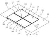
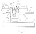
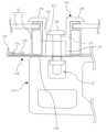
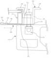
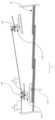
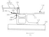
図1は、一実施形態におけるパネル構造体の模式的斜視図である。図2は、図1の矢印2A方向から見たパネル構造体の部分的側面図である。図3は、図2の矢印3A付近の拡大図である。ただし、図3では、便宜上、後述する設置面90は描かれていない。
[First embodiment]
FIG. 1 is a schematic perspective view of a panel structure in one embodiment. FIG. 2 is a partial side view of the panel structure viewed from the direction of arrow 2A in FIG. FIG. 3 is an enlarged view of the vicinity ofarrow 3A in FIG. However, in FIG. 3, for convenience, aninstallation surface 90, which will be described later, is not depicted.

パネル構造体は、少なくとも1つのパネル状部材10と、複数のパネル状部材用の固定具100と、を有していてよい。固定具100は、少なくとも1つのパネル状部材10を設置面90に設置するために用いられる。好ましくは、パネル構造体は、少なくとも一方向に並んだ複数のパネル状部材10を有していてよい。 The panel structure may have at least one panel-like member 10 andfixtures 100 for a plurality of panel-like members. Fixture 100 is used to install at least one panel-like member 10 oninstallation surface 90 . Preferably, the panel structure may include a plurality of panel-like members 10 arranged in at least one direction.

固定具100は、それぞれのパネル状部材10の互いに対向する一辺を支持している。より具体的には、パネル状部材10の一辺と、パネル状部材10の別の一辺とが、それぞれ複数の固定具100によって支持されている。 Thefixture 100 supports one side of eachpanel member 10 that faces each other. More specifically, one side of the panel-like member 10 and another side of the panel-like member 10 are each supported by a plurality offixtures 100.

各々のパネル状部材10は、例えば太陽電池パネルのような光電変換パネルであってよい。パネル状部材10は、パネル12及びフレーム14を有していてよい。パネル状部材10が太陽電池モジュールである場合、パネル12は、太陽エネルギーを電気エネルギーに変換する光電変換パネルに相当し、フレーム14は光電変換パネルの周囲に設けられた縁に相当する。 Each panel-shaped member 10 may be a photoelectric conversion panel such as a solar cell panel, for example. Thepanel member 10 may include apanel 12 and aframe 14. When the panel-shaped member 10 is a solar cell module, thepanel 12 corresponds to a photoelectric conversion panel that converts solar energy into electrical energy, and theframe 14 corresponds to an edge provided around the photoelectric conversion panel.

本実施形態では、設置面90は、傾斜した屋根であってよい。本明細書において、傾斜した屋根において最大傾斜線に沿って高い方から低い方へ向かう方向を「流れ方向F1」と称する。流れ方向F1の上流側を「水上側」と称する。流れ方向F1の下流側を「水下側」と称する。また、流れ方向F1と直交し、かつ屋根面に沿った方向を「横方向F2」と称する。 In this embodiment, theinstallation surface 90 may be a sloped roof. In this specification, the direction from the higher side to the lower side along the maximum slope line of the sloped roof is referred to as the "flow direction F1." The upstream side in the flow direction F1 is referred to as the "above water side". The downstream side in the flow direction F1 is referred to as the "underwater side". Further, a direction perpendicular to the flow direction F1 and along the roof surface is referred to as a "lateral direction F2."

本実施形態では、建造物の屋根は、屋根材として複数のスレート92が敷き詰められたスレート屋根である。屋根に設けられた複数のスレート92は流れ方向F1と横方向F2とに並んでいてよい。なお、流れ方向F1に互いに隣接するスレート12は、部分的に重ねられており、これによりスレート屋根の表面に段差が形成されている。 In this embodiment, the roof of the building is a slate roof on which a plurality ofslates 92 are laid as roofing material. The plurality ofslates 92 provided on the roof may be arranged in the flow direction F1 and the lateral direction F2. Note that theslates 12 adjacent to each other in the flow direction F1 are partially overlapped, thereby forming a step on the surface of the slate roof.

本実施形態では、パネル状部材10は、流れ方向F1と横方向F2の両方に並んでいてよい。この代わりに、複数のパネル状部材10は、流れ方向F1と横方向F2の少なくとも一方に沿って並んでいてもよい。 In this embodiment, the panel-like members 10 may be arranged in both the flow direction F1 and the lateral direction F2. Alternatively, the plurality of panel-like members 10 may be arranged along at least one of the flow direction F1 and the lateral direction F2.

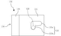
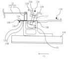
図4は、第1実施形態に係るパネル状部材用の固定具の分解斜視図である。なお、図4では、便宜上、後述する第1締結部材は描かれていない。図5は、第1実施形態に係る固定具及びパネル状部材の部分的拡大側面図である。なお、図5では、便宜上、後述する基部は描かれていない。図6は、第1実施形態に係る固定具を構成する係合部材の上面図である。図6では、後述する第1締結部材150の位置が便宜上点線にて描かれている。図7は、第1実施形態において、第1締結部材を緩めた状態で固定具をパネル状部材に取り付ける方法を説明する部分的拡大側面図である。図7では、便宜上、後述する基部は描かれていない。図8は、図7に示す状態における第1締結部材と係合部材の位置関係を説明するための係合部材の上面図である。図8では、後述する第1締結部材150の位置が便宜上点線にて描かれている。 FIG. 4 is an exploded perspective view of a fixture for a panel-shaped member according to the first embodiment. Note that in FIG. 4, for convenience, a first fastening member, which will be described later, is not illustrated. FIG. 5 is a partially enlarged side view of the fixture and panel-like member according to the first embodiment. Note that in FIG. 5, for convenience, a base portion, which will be described later, is not depicted. FIG. 6 is a top view of the engagement member that constitutes the fixture according to the first embodiment. In FIG. 6, the position of afirst fastening member 150, which will be described later, is illustrated by a dotted line for convenience. FIG. 7 is a partially enlarged side view illustrating a method of attaching the fixture to the panel-like member with the first fastening member loosened in the first embodiment. In FIG. 7, for convenience, a base portion, which will be described later, is not depicted. FIG. 8 is a top view of the engaging member for explaining the positional relationship between the first fastening member and the engaging member in the state shown in FIG. 7. FIG. In FIG. 8, the position of afirst fastening member 150, which will be described later, is illustrated by a dotted line for convenience.

複数の固定具100は、パネル状部材10の端に位置し、パネル状部材10を設置面90に固定している。具体的には、固定具100は、パネル状部材10のフレーム14を支持していてよい。好ましくは、固定具100は、互いに隣接するパネル状部材10どうしの間に位置し、互いに隣接する一対のパネル状部材10の両方を支持可能に構成されていてよい。もっとも、固定具100は、隣接するパネル状部材10が存在しない側のパネル状部材10の端では、1つのパネル状部材10のみを支持するよう構成されていてもよい。 The plurality offixtures 100 are located at the ends of the panel-shapedmember 10 and fix the panel-shapedmember 10 to theinstallation surface 90. Specifically, thefixture 100 may support theframe 14 of the panel-like member 10. Preferably, thefixture 100 is located between the panel-shapedmembers 10 adjacent to each other, and may be configured to be able to support both of the pair of panel-shapedmembers 10 adjacent to each other. However, thefixture 100 may be configured to support only one panel-like member 10 at the end of the panel-like member 10 on the side where no adjacent panel-like member 10 exists.

固定具100は、支持部材110と、締め具120と、係合部材130と、基部140と、第1締結部材150と、第2締結部材160と、第3締結部材170と、を有していてよい。 Thefixture 100 includes asupport member 110, afastener 120, an engagingmember 130, abase 140, afirst fastening member 150, asecond fastening member 160, and athird fastening member 170. It's fine.

基部140は、設置面90に当接しており、パネル状部材10を支持する支持部材110を支える土台である。基部140は、固定具100を設置面90に締結するための第2締結部材160を挿通する第1挿通孔142を有していてよい。すなわち、第2締結部材160は、基部140に設けられた第1挿通孔142を通って設置面90、例えばスレート92に達する。これにより、固定具100が設置面90に固定される。第2締結部材160は、特に制限されないが、例えばボルト及びナットにより構成されていてもよく、アンカーにより構成されていてもよい。 Thebase 140 is in contact with theinstallation surface 90 and is a base that supports thesupport member 110 that supports the panel-shapedmember 10. The base 140 may have afirst insertion hole 142 through which asecond fastening member 160 for fastening thefixture 100 to theinstallation surface 90 is inserted. That is, thesecond fastening member 160 passes through thefirst insertion hole 142 provided in thebase 140 and reaches theinstallation surface 90, for example, theslate 92. Thereby, thefixture 100 is fixed to theinstallation surface 90. Thesecond fastening member 160 is not particularly limited, but may be composed of, for example, a bolt and a nut, or may be composed of an anchor.

基部140は、支持部材110を支持可能な支持部を有する。当該支持部は、支持部材110をスライド移動可能に保持するレール144であってよい。レール144は、例えば流れ方向F1に支持部材110をスライド可能に保持するよう、流れ方向F1に延びていてよい。支持部材110のスライド方向におけるレール144の長さは特に限定されないが、レール144は、基部140の一端から他端まで延びていてよい。 Thebase 140 has a support part that can support thesupport member 110. The support portion may be arail 144 that slidably holds thesupport member 110. Therails 144 may extend in the flow direction F1, for example, to slidably retain thesupport member 110 in the flow direction F1. Although the length of therail 144 in the sliding direction of thesupport member 110 is not particularly limited, therail 144 may extend from one end of the base 140 to the other end.

基部140は、横方向F2おける両側部において、上方に立設した一対の側壁部146を有していてよい。側壁部146は、レール144と同様に、流れ方向F1に延びていてよい。側壁部146の高さは、レール144の高さと実質的に同じであることが好ましい。この場合、支持部材110は、レール144の上面と一対の側壁部146の上面により支えられる。 Thebase portion 140 may have a pair ofside wall portions 146 erected upward on both sides in the lateral direction F2. Theside wall portion 146, like therail 144, may extend in the flow direction F1. Preferably, the height ofsidewall portion 146 is substantially the same as the height ofrail 144. In this case, thesupport member 110 is supported by the upper surface of therail 144 and the upper surface of the pair ofside wall portions 146.

基部140は、第3締結部材170によって後述する支持部材110に締結される。第3締結部材170は、特に制限されないが、例えばボルト及びナットにより構成されていてよい。 Thebase 140 is fastened to asupport member 110, which will be described later, by athird fastening member 170. Thethird fastening member 170 may be formed of, for example, a bolt and a nut, although it is not particularly limited.

本実施形態では、第3締結部材170の一部、例えばボルトの頭部が、レール144内に配置されていてよい。第3締結部材170の残りの一部、例えばボルトの螺子切り部分は、基部140のレール144よりも上方に突出していてよい。この状態で、第3締結部材170は、支持部材110とともにレール144に沿ってスライド移動可能になっていてよい。なお、第3締結部材170が強く締結されたとき、支持部材110は、基部140に関してスライド移動できないよう基部140に固定される。 In this embodiment, a portion of thethird fastening member 170, for example the head of the bolt, may be located within therail 144. The remaining portion of thethird fastening member 170, for example, the threaded portion of the bolt, may protrude above therail 144 of thebase portion 140. In this state, thethird fastening member 170 may be able to slide along therail 144 together with thesupport member 110. Note that when thethird fastening member 170 is strongly fastened, thesupport member 110 is fixed to the base 140 so that it cannot slide relative to thebase 140.

第1挿通孔142は、レール144を挟んで両側に設けられていることが好ましい。これにより、固定具100の施工中にレール144が傾かないよう基部140をしっかりと締結することができる。第1挿通孔142は、基部140の、流れ方向F1における水上側の端部近傍のみに形成されていることが好ましいが、これに限定されるものではない。 It is preferable that the first insertion holes 142 are provided on both sides with therail 144 in between. Thereby, the base 140 can be firmly fastened so that therail 144 does not tilt during construction of thefixture 100. Thefirst insertion hole 142 is preferably formed only near the end of the base 140 on the water side in the flow direction F1, but is not limited thereto.

第3締結部材170及び第1挿通孔142は、支持部材110が1つのパネル状部材10、本実施形態では水下側のパネル状部材10を支持した状態において、設置面90に交差する方向からアクセス可能に構成されている。具体的一例として、第3締結部材170及び第1挿通孔142の両方が、支持部材110がパネル状部材10を積載した状態において、後述する締め具120に関して一方側、本実施形態では水上側に設けられている。水下側のパネル状部材10が支持部材110に積載されているが、水上側のパネル状部材10が支持部材110に積載されていない状態において、第3締結部材170及び第1挿通孔142の両方は、設置面90に交差する方向(上方)からアクセス可能になっている。 Thethird fastening member 170 and thefirst insertion hole 142 are inserted from the direction intersecting theinstallation surface 90 when thesupport member 110 supports one panel-like member 10, in this embodiment, the panel-like member 10 on the underwater side. Configured to be accessible. As a specific example, both thethird fastening member 170 and thefirst insertion hole 142 are connected to one side with respect to afastener 120, which will be described later, when thesupport member 110 is loaded with the panel-like member 10, which is the above-water side in this embodiment. It is provided. In a state where the panel-like member 10 on the underwater side is loaded on thesupport member 110 but the panel-like member 10 on the water side is not loaded on thesupport member 110, thethird fastening member 170 and thefirst insertion hole 142 Both are accessible from the direction intersecting the installation surface 90 (from above).

次に、支持部材110の具体的な構成の一例についてより詳細に説明する。支持部材110は、第3締結部材170が挿通される第2挿通孔113を有する下部112と、下部112よりも上方に位置する上部111と、を有していてよい。下部112は、基部140、具体的には基部140のレール144の上面に当接していてよい。第3締結部材170は、支持部材110の下部112に形成された第2挿通孔113と、基部140に形成された第1挿通孔142とを通って、支持部材110と基部140とを互いに締結可能に構成されている。 Next, an example of a specific configuration of thesupport member 110 will be described in more detail. Thesupport member 110 may include alower portion 112 having asecond insertion hole 113 into which thethird fastening member 170 is inserted, and anupper portion 111 located above thelower portion 112. Thelower portion 112 may abut the upper surface of thebase 140 , specifically therail 144 of thebase 140 . Thethird fastening member 170 fastens thesupport member 110 and the base 140 to each other through thesecond insertion hole 113 formed in thelower part 112 of thesupport member 110 and thefirst insertion hole 142 formed in thebase 140. configured to be possible.

支持部材110は、互いに隣接する一対のパネル状部材10を積載可能な積載部116を有する。当該積載部116は、支持部材110の上部111の上面によって規定されていてよい。 Thesupport member 110 has aloading section 116 on which a pair of panel-like members 10 adjacent to each other can be loaded. Theloading portion 116 may be defined by the upper surface of theupper portion 111 of thesupport member 110.

また、支持部材110は、後述する締め具120との締結に用いられる第1締結部材150を通す第3挿通孔117を有していてよい。第1締結部材150は、特に制限されないが、例えばボルト及びナットにより構成されていてよい。第3挿通孔117は、支持部材110の上部111に形成されていてよい。この場合、互いに隣接する一対のパネル状部材10は、第3挿通孔117を挟んで両側に積載されていてよい。 Further, thesupport member 110 may have athird insertion hole 117 through which afirst fastening member 150 used for fastening with afastener 120 described later is passed. Thefirst fastening member 150 may be made of, for example, a bolt and a nut, although it is not particularly limited. Thethird insertion hole 117 may be formed in theupper part 111 of thesupport member 110. In this case, a pair of panel-like members 10 adjacent to each other may be stacked on both sides with thethird insertion hole 117 in between.

第1締結部材150がボルト及びナットにより構成される場合、支持部材110は、好ましくは第1締結部材150を構成するナットを収容する収容スペースS1を有していてよい(図5参照)。この場合、第3挿通孔117は、収容スペースS1の上方に設けられていてよい。第1締結部材150を構成するボルトのネジ部は、第3挿通孔117を通って上方に延びていてよい。 When thefirst fastening member 150 is composed of a bolt and a nut, thesupport member 110 may preferably have an accommodation space S1 for accommodating the nut constituting the first fastening member 150 (see FIG. 5). In this case, thethird insertion hole 117 may be provided above the accommodation space S1. The threaded portion of the bolt constituting thefirst fastening member 150 may extend upward through thethird insertion hole 117.

第3挿通孔117は、第1締結部材150の径よりも横方向F2に長くてもよい。この場合、第1締結部材150、締め具120及び係合部材130は、パネル状部材10ごと横方向F2に微調整可能となる。 Thethird insertion hole 117 may be longer than the diameter of thefirst fastening member 150 in the lateral direction F2. In this case, thefirst fastening member 150, thefastener 120, and the engagingmember 130 can be finely adjusted together with the panel-like member 10 in the lateral direction F2.

締め具120は、支持部材110の上方に設けられる。締め具120は、積載部116上に積載させた一対のパネル状部材10を積載部116に向けて押圧可能に構成されている。第1締結部材150は、支持部材110に締め具120を締結可能に構成されている。このため、締め具120は、第1締結部材150の一部を挿通可能な第4挿通孔123を有していてよい。 Afastener 120 is provided above thesupport member 110. Thefastener 120 is configured to be able to press the pair of panel-shapedmembers 10 stacked on the stackingsection 116 toward the stackingsection 116 . Thefirst fastening member 150 is configured to be able to fasten thefastener 120 to thesupport member 110. Therefore, thefastener 120 may have afourth insertion hole 123 through which a part of thefirst fastening member 150 can be inserted.

締め具120は、横方向F2から見て略U字形の本体部122と、本体部122の頂部から流れ方向F1の両側に突出したフランジ129と、を有していてよい。第4挿通孔123は、略U字形の本体部122の底に形成されていてよい。 Thefastener 120 may include amain body 122 that is substantially U-shaped when viewed from the lateral direction F2, andflanges 129 that protrude from the top of themain body 122 on both sides in the flow direction F1. Thefourth insertion hole 123 may be formed at the bottom of the substantially U-shapedmain body portion 122.

互いに隣接する一対のパネル状部材10が、支持部材110の積載部116上に積載された状態において、締め具120の本体部122は、一対のパネル状部材10どうしの間に位置する。一対のフランジ129のそれぞれは、第1締結部材150が締結された状態において、互いに隣接する一対のパネル状部材10の端、例えばフレーム14を上方から下方に押さえる。したがって、互いに隣接する一対のパネル状部材10のそれぞれは、支持部材110の積載部116と締め具120のフランジ129との間に挟まれて固定される。 In a state where a pair of panel-like members 10 adjacent to each other are stacked on the stackingportion 116 of thesupport member 110, themain body portion 122 of thefastener 120 is located between the pair of panel-like members 10. Each of the pair offlanges 129 presses the ends of the pair of mutually adjacent panel-shapedmembers 10, for example, theframe 14, from above to below in a state in which thefirst fastening member 150 is fastened. Therefore, each of the pair of panel-like members 10 adjacent to each other is sandwiched and fixed between theloading portion 116 of thesupport member 110 and theflange 129 of thefastener 120.

締め具120は、略U字形の本体部122の底から下方に突出した突出部124を有していることが好ましい(図4及び図5参照)。この場合、突出部124は、支持部材110に当接していてよい。突出部124は、第4挿通孔123に関して、後述する係合部材130の挟持部134とは反対側に設けられていてよい。この代わりに、締め具120は、突出部124を有しておらず、略U字形の本体部122の底が直接支持部材110に当接していてもよい。 Preferably, thefastener 120 has aprotrusion 124 that protrudes downward from the bottom of the generally U-shaped main body 122 (see FIGS. 4 and 5). In this case, theprotrusion 124 may be in contact with thesupport member 110. The protrudingpart 124 may be provided on the opposite side of the holdingpart 134 of the engagingmember 130, which will be described later, with respect to thefourth insertion hole 123. Alternatively, thefastener 120 may not have theprotrusion 124 and the bottom of the substantially U-shapedmain body 122 may directly abut thesupport member 110.

係合部材130は、第1締結部材150を緩めた状態又は第1締結部材150を取り外した状態で、互いに隣接する一対のパネル状部材10のうちの一方の積載部116からの脱離を防止するよう構成されている。 Theengagement member 130 prevents one of the pair of mutually adjacent panel-like members 10 from detaching from theloading section 116 when thefirst fastening member 150 is loosened or removed. is configured to do so.

係合部材130は、支持部材110と締め具120との間に配置されている。好ましくは、係合部材130は、第1締結部材150を挿通させる孔部132を有する。これにより、係合部材130は、支持部材110と締め具120とを互いに締結可能な第1締結部材150によって、支持部材110及び締め具120から脱離しないよう構成されている。また、係合部材130は、第1締結部材150を緩めた状態であっても、締め具120が第1締結部材150を介して支持部材110に脱離しない限り、支持部材110及び締め具120から脱離しない。Engagement member 130 is disposed betweensupport member 110 andfastener 120. Preferably, theengagement member 130 has ahole 132 through which thefirst fastening member 150 is inserted. Thereby, theengagement member 130 is configured not to be detached from thesupport member 110 and thefastener 120 due to thefirst fastening member 150 that can fasten thesupport member 110 and thefastener 120 to each other. Further, even if thefirst fastening member 150 is in a loosened state, theengagement member 130 is connected to thesupport member 110 and thefastener 120 as long as thefastener 120 is not detached from thesupport member 110 via thefirst fastening member 150. Don't separate from it.

係合部材130は、互いに隣接する一対のパネル状部材10のうちの一方のフレーム14の底部を挟持可能な挟持部134を有していてよい。第1実施形態では、係合部材130は、支持部材110と締め具120との間に挟まれる板部131と、板部131の先端において折り返された折り返し部135と、を有していてよい。挟持部134は、この折り返し部135によって構成されていてよい。 The engagingmember 130 may have aclamping part 134 that can clamp the bottom of one of theframes 14 of the pair of panel-shapedmembers 10 adjacent to each other. In the first embodiment, theengagement member 130 may include aplate portion 131 sandwiched between thesupport member 110 and thefastener 120, and a foldedportion 135 folded back at the tip of theplate portion 131. . The holdingportion 134 may be configured by this foldedportion 135.

パネル状部材10のフレーム14の底部14aは、締め具120から離れる方向に突出していてよい。係合部材130の挟持部134は、このパネル状部材10のフレーム14の底部14aを挟み込んでいる(図5参照)。 Thebottom portion 14a of theframe 14 of the panel-like member 10 may protrude in a direction away from thefastener 120. The holdingportion 134 of the engagingmember 130 holds thebottom portion 14a of theframe 14 of the panel member 10 (see FIG. 5).

係合部材130の板部131は、第1締結部材150により締結された状態で、支持部材110と締め具120との間で互いに押圧される。係合部材130は、支持部材110と締め具120との間で互いに押圧される部分から少なくとも一方向に延びている。折り返し部135は、係合部材130の先端で、締め具120の方に向かって折り返された部分によって構成されている。 Theplate portion 131 of theengagement member 130 is pressed together between thesupport member 110 and thefastener 120 while being fastened by thefirst fastening member 150 . Theengagement member 130 extends in at least one direction from a portion of thesupport member 110 and thefastener 120 that are pressed against each other. The foldedportion 135 is formed by a portion folded back toward thefastener 120 at the tip of theengagement member 130 .

上記構成により、第1締結部材150が緩められたとしても、互いに隣接する一対のパネル状部材10のうちの一方が積載部116から脱離することを防止できる。言い換えると、第1締結部材150が緩められたとしても、固定具100は、係合部材130を介して互いに隣接する一対のパネル状部材10のうちの一方に係合した状態を維持できる。 With the above configuration, even if thefirst fastening member 150 is loosened, one of the pair of mutually adjacent panel-shapedmembers 10 can be prevented from detaching from theloading section 116. In other words, even if thefirst fastening member 150 is loosened, thefixture 100 can remain engaged with one of the pair ofadjacent panel members 10 via theengagement member 130.

係合部材130は、第1締結部材150を緩めた状態又は第1締結部材150を取り外した状態で、一対のパネル状部材10が並ぶ方向(以下、「列方向」と称する。)にスライド可能に構成されていることが好ましい。より好ましくは、係合部材130は、列方向にスライド可能な第1状態と、当該列方向にスライド不能な第2状態との間で可変に構成されている。第1実施形態では、列方向は、流れ方向F1に一致する。この代わりに、列方向は、横方向F2に一致していても良い。この場合、固定具100は、横方向F2に互いに隣接するパネル状部材10どうしの間に位置していてよい。 The engagingmember 130 is slidable in the direction in which the pair of panel-shapedmembers 10 are lined up (hereinafter referred to as the "column direction") with thefirst fastening member 150 loosened or removed. It is preferable that the configuration is as follows. More preferably, the engagingmember 130 is configured to be variable between a first state in which it is slidable in the row direction and a second state in which it is not slidable in the row direction. In the first embodiment, the column direction corresponds to the flow direction F1. Alternatively, the column direction may coincide with the horizontal direction F2. In this case, thefixture 100 may be located between the panel-like members 10 that are adjacent to each other in the lateral direction F2.

具体的には、係合部材130に形成された孔部132は、列方向に延びた第1部分132aと、第1部分132aに繋がっており、列方向から交差する方向に延びた第2部分132bと、を有していてよい(特に図6参照)。図6に示す例では、孔部132は、上面視でL字形に形成されている。より具体的には、第2部分132bは、列方向に延びた第1部分132aの、挟持部134側の端に連通している。 Specifically, thehole 132 formed in theengagement member 130 includes afirst portion 132a extending in the column direction and a second portion connected to thefirst portion 132a and extending in a direction crossing from the column direction. 132b (see especially FIG. 6). In the example shown in FIG. 6, thehole 132 is formed in an L-shape when viewed from above. More specifically, thesecond portion 132b communicates with the end of thefirst portion 132a extending in the column direction on the holdingportion 134 side.

孔部132を構成する第1部分132a及び第2部分132bのそれぞれは、第1締結部材150を挿通可能な幅を有している。これにより、第1締結部材150が図8に示す位置にある場合、係合部材130に関する第1締結部材150の相対位置は、列方向に延びた第1部分132aに沿って列方向に移動可能である(図8に示す)。したがって、係合部材130は、第1締結部材150が緩められた状態で、支持部材110及び締め具120に関して列方向にスライド可能な状態(前述の第1状態)になり得る。 Each of thefirst portion 132a and thesecond portion 132b constituting thehole 132 has a width that allows thefirst fastening member 150 to be inserted therethrough. As a result, when thefirst fastening member 150 is in the position shown in FIG. 8, the relative position of thefirst fastening member 150 with respect to the engagingmember 130 can be moved in the column direction along thefirst portion 132a extending in the column direction. (shown in FIG. 8). Therefore, theengagement member 130 can be in a state where it can slide in the column direction with respect to thesupport member 110 and the fastener 120 (the first state described above) with thefirst fastening member 150 being loosened.

第1締結部材150が図6に示す位置にある場合、係合部材130に関する第1締結部材150の相対位置は、列方向には実質的に移動不能である。これは、列方向における第2部分132bの幅が、第1締結部材150の径とほぼ同程度であるからである。これにより、係合部材130は、第1締結部材150が緩められた状態であっても、支持部材110及び締め具120に関して列方向にスライド不能な状態(前述の第2状態)にもなり得る。 When thefirst fastening member 150 is in the position shown in FIG. 6, the relative position of thefirst fastening member 150 with respect to theengagement member 130 is substantially immovable in the column direction. This is because the width of thesecond portion 132b in the column direction is approximately the same as the diameter of thefirst fastening member 150. As a result, theengagement member 130 may be in a state in which it cannot slide in the column direction with respect to thesupport member 110 and the fastener 120 (the above-mentioned second state) even when thefirst fastening member 150 is in a loosened state. .

前述した第1部分132a及び第2部分132bの構造により、係合部材130は、第1締結部材150を緩めた状態で、列方向にスライド可能な第1状態と、当該列方向にスライド不能な第2状態との間で可変に構成される。 Due to the structure of thefirst portion 132a and thesecond portion 132b described above, theengagement member 130 can be in a first state in which it is slidable in the row direction when thefirst fastening member 150 is loosened, and in a state in which it is not slidable in the row direction. It is configured to be variable between the second state and the second state.

以下、固定具100をパネル状部材10の一辺に取り付ける方法について説明する。まず、第1締結部材150を緩めた状態で、パネル状部材10が取り付けられていない固定具100の係合部材130を第1状態にし、係合部材130と第1締結部材150との相対位置を図8に示す状態にする。この状態における固定具100が、図7に示されている。図7に示す状態において、係合部材130の挟持部132は、第1締結部材150及び締め具120の本体部122から最も離れた位置に退避する。したがって、この状態において、パネル状部材10のフレーム14の底部14aを、係合部材130の挟持部132に干渉することなく、支持部材110の積載部116とフランジ129との間、厳密には支持部110の積載部116上の係合部材130の板部131とフランジ129との間に挿入することができる(図7)。フレーム14の底部14aは、この状態において、未だ挟持部132によって挟持されていない。 Hereinafter, a method for attaching thefixture 100 to one side of the panel-shapedmember 10 will be described. First, with thefirst fastening member 150 loosened, the engagingmember 130 of thefixture 100 to which the panel-like member 10 is not attached is brought into the first state, and the relative position of the engagingmember 130 and thefirst fastening member 150 is into the state shown in FIG. Thefixture 100 in this state is shown in FIG. In the state shown in FIG. 7, the holdingportion 132 of theengagement member 130 is retracted to the position farthest from thefirst fastening member 150 and themain body portion 122 of thefastener 120. Therefore, in this state, thebottom part 14a of theframe 14 of the panel-like member 10 is placed between theloading part 116 of the supportingmember 110 and theflange 129, strictly speaking, without interfering with the holdingpart 132 of the engagingmember 130. It can be inserted between theplate part 131 of theengagement member 130 on theloading part 116 of thepart 110 and the flange 129 (FIG. 7). In this state, thebottom portion 14a of theframe 14 is not yet held by the holdingportions 132.

次に、係合部材130を支持部材110及び締め具120に関してスライドさせる。より具体的には、係合部材130の挟持部132が第1締結部材150及び締め具120に近づくよう、係合部材130を列方向にスライドさせる。これにより、係合部材130の挟持部132が、積載部116上に積載されたパネル状部材10のフレーム14の底部14aを挟持する。さらに、係合部材130を列方向に交差する方向にスライドさせることにより、係合部材130を、当該列方向にスライド不能な第2状態にする(図5及び図6参照)。これにより、第1締結部材150が緩められた状態であっても、パネル状部材10は、係合部材130を介して支持部材110及び締め具120に係合した状態になる。このように、係合部材130は、第1締結部材150が緩められた状態において、パネル状部材10の積載部116からの脱離を防止する(仮止め状態)。 Next, theengagement member 130 is slid relative to thesupport member 110 and thefastener 120. More specifically, the engagingmember 130 is slid in the row direction so that the holdingportion 132 of the engagingmember 130 approaches thefirst fastening member 150 and thefastener 120. Thereby, the clampingpart 132 of the engagingmember 130 clamps thebottom part 14a of theframe 14 of the panel-like member 10 stacked on the stackingpart 116. Further, by sliding the engagingmember 130 in a direction crossing the row direction, the engagingmember 130 is placed in a second state in which it cannot slide in the row direction (see FIGS. 5 and 6). As a result, even if thefirst fastening member 150 is loosened, thepanel member 10 is engaged with thesupport member 110 and thefastener 120 via theengagement member 130. In this way, theengagement member 130 prevents the panel-like member 10 from coming off from theloading section 116 when thefirst fastening member 150 is loosened (temporarily fixed state).

後述するように、第1締結部材150は、固定具100が設置面90上に固定された後に強固に締結されればよい。これにより、パネル状部材10は、支持部材110と締め具120の間で強固に支持される。 As will be described later, thefirst fastening member 150 may be firmly fastened after thefixture 100 is fixed on theinstallation surface 90. Thereby, the panel-shapedmember 10 is firmly supported between thesupport member 110 and thefastener 120.

ここで、前述したように、締め具120は、略U字形の本体部122の底から下方に突出した突出部124を有していることが好ましい(図4及び図5参照)。この場合、第1締結部材150が強固に締結されるほど、係合部材130の挟持部134側に位置するフランジ129が、突出部124の下端を軸にして回転する方向に移動しようとする。そのため、係合部材130の挟持部134側に位置するフランジ129が、パネル状部材10のフレーム14を積載部116に向けて強く押圧する。これにより、仮止めされていたパネル状部材10は、強固に支持されることになる。 Here, as described above, thefastener 120 preferably has aprotrusion 124 that protrudes downward from the bottom of the substantially U-shaped main body 122 (see FIGS. 4 and 5). In this case, the more firmly thefirst fastening member 150 is fastened, the more theflange 129 of theengagement member 130 located on the holdingpart 134 side tends to move in the direction of rotation about the lower end of theprotruding part 124. Therefore, theflange 129 located on the side of the holdingpart 134 of the engagingmember 130 strongly presses theframe 14 of the panel-shapedmember 10 toward theloading part 116. As a result, the temporarily fixedpanel member 10 is firmly supported.

次に、固定具を備えたパネル状部材を含むパネル状部材組合体について説明する。図9は、固定具を備えたパネル状部材を含むパネル状部材組合体の上面図である。図9に示すパネル状部材組立体は、パネル状部材10と、前述した固定具100と、を有する。固定具100は、パネル状部材10の一辺、好ましくは一辺のみに係合している。 Next, a panel-like member assembly including a panel-like member provided with a fixture will be described. FIG. 9 is a top view of a panel-like member assembly including a panel-like member with a fixture. The panel-shaped member assembly shown in FIG. 9 includes a panel-shapedmember 10 and theaforementioned fixture 100. Thefixture 100 engages one side of the panel-like member 10, preferably only one side.

図9に示す態様では、2つの固定具100が、パネル状部材10の一辺のみに取り付けられている。この代わりに、少なくとも3つの固定具100がパネル状部材10の一辺に取り付けられていてもよい。 In the embodiment shown in FIG. 9, twofixtures 100 are attached to only one side of the panel-like member 10. Alternatively, at least threefixtures 100 may be attached to one side of the panel-like member 10.

パネル状部材10は、前述した仮止め状態で、固定具100の支持部材110の積載部116上に積載されていてよい。なお、固定具100は、互いに隣接する一対のパネル状部材10を積載可能な構造を有するが、固定具100は、図9に示す状態において1つのパネル状部材10のみを積載した状態である。パネル状部材組合体は、このような図9に示す状態で製造され、出荷されることが好ましい。すなわち、パネル状部材組合体は、設置面90に設置する前において、固定具100が仮止めされた一辺を有するパネル状部材10を含む。 Thepanel member 10 may be stacked on the stackingportion 116 of thesupport member 110 of thefixture 100 in the temporarily fixed state described above. Note that although thefixture 100 has a structure that allows a pair of panel-shapedmembers 10 adjacent to each other to be loaded, thefixture 100 is in a state shown in FIG. 9 in which only one panel-shapedmember 10 is loaded. It is preferable that the panel-like member assembly be manufactured and shipped in the state shown in FIG. 9 . That is, the panel-like member assembly includes a panel-like member 10 having one side to which afixture 100 is temporarily fixed before being installed on theinstallation surface 90.

これにより、以下で説明するように、施工者が屋根のような設置面90上において行うべき作業において、パネル状部材10と固定具100との取り付けの手間が削減される。 As a result, as will be explained below, the effort required to attach the panel-like member 10 and thefixture 100 is reduced when the builder performs work on theinstallation surface 90 such as a roof.

以下、パネル状部材の設置方法について説明する。図10は、パネル状部材を設置面に設置する方法の一ステップを示す図である。図11は、図10に続くステップを示す図である。図12は、図11に示すステップを側方から見た図である。図13は、図10及び図11に示すステップを示す図である。図14は、図13に続くステップを側方から見た図である。 Hereinafter, a method for installing the panel-shaped member will be explained. FIG. 10 is a diagram showing one step of a method for installing a panel-like member on an installation surface. FIG. 11 is a diagram showing steps following FIG. 10. FIG. 12 is a side view of the step shown in FIG. 11. FIG. 13 is a diagram showing the steps shown in FIGS. 10 and 11. FIG. 14 is a side view of the step following FIG. 13.

まず、図9に示すようなパネル状部材組立体を複数準備する。すなわち、固定具100が仮止めされた一辺を有するパネル状部材10を複数準備する。 First, a plurality of panel-like member assemblies as shown in FIG. 9 are prepared. That is, a plurality of panel-like members 10 each having one side to which thefixture 100 is temporarily fixed are prepared.

次に、図10に示すように、パネル状部材10の列方向において最も端に位置すべき固定具100を設置面90上に固定する。図10では、最も水下側の固定具100を設置面90上に固定する。ここで、最も水下側の固定具100は、前述した構造と同じ構造を有していてよい。この代わりに、最も水下側の固定具100の構造は、1つのパネル状部材10を支持すればよいため、前述した固定具100とは異なる構造であってもよい。 Next, as shown in FIG. 10, thefixture 100, which should be located at the end of the panel-shapedmembers 10 in the row direction, is fixed on theinstallation surface 90. In FIG. 10, thefixture 100 closest to the water is fixed on theinstallation surface 90. Here, thefixture 100 closest to the bottom of the water may have the same structure as described above. Instead, the structure of thefixture 100 closest to the bottom of the water may have a structure different from that of thefixture 100 described above, since it is sufficient to support one panel-shapedmember 10.

次に、最も水下側の固定具100に、パネル状部材10の一辺を固定する(図11参照)。この際に、パネル状部材組立体を構成するパネル状部材10の、仮止めされた固定具100が係合していない一辺を、既に設置面90に固定した最も水下側の固定具100に固定する。最も水下側の固定具100に固定するパネル状部材10の一辺は、パネル状部材10に予め仮止めされた固定具100を含む一辺とは反対側の一辺であることが好ましい。これにより、パネル状部材10に予め仮止めされた固定具100は、図11に示すように、パネル状部材10の水上側に位置する。パネル状部材10に予め仮止めされた固定具100は、図12に示すように、第2締結部材160によって設置面90に固定される。なお、この段階で、新たに設置面90に固定された固定具100の第1締結部材150は、未だ緩められた状態である。 Next, one side of the panel-like member 10 is fixed to thefixture 100 that is closest to the bottom of the water (see FIG. 11). At this time, one side of the panel-shapedmember 10 constituting the panel-shaped member assembly that is not engaged with the temporarily fixedfixture 100 is attached to thefixture 100 closest to the water that has already been fixed to theinstallation surface 90. Fix it. It is preferable that one side of thepanel member 10 to be fixed to thefixture 100 closest to the bottom of the water is one side opposite to the side including thefixture 100 temporarily fixed to thepanel member 10 in advance. As a result, thefixture 100 temporarily fixed to the panel-shapedmember 10 is located on the water side of the panel-shapedmember 10, as shown in FIG. Thefixture 100 that has been temporarily secured to the panel-shapedmember 10 in advance is secured to theinstallation surface 90 by thesecond fastening member 160, as shown in FIG. Note that, at this stage, thefirst fastening member 150 of thefixture 100 newly fixed to theinstallation surface 90 is still in a loosened state.

次に、直前に設置したパネル状部材10に仮止めされていた固定具100に、別のパネル状部材10の一辺を固定する(図13参照)。具体的には、当該別のパネル状部材組立体を構成するパネル状部材10の、仮止めされている固定具100が係合していない一辺を、設置面90に固定された固定具100の積載部116に積載させる。この際に、新たに設置するパネル状部材10の、仮止めされた固定具100が係合していない一辺を、既に設置面90に固定した固定具100に固定する。この際に、新しく設置するパネル状部材10のフレーム14の一端を、既に設置面90上に固定された固定具100の積載部116とフランジ129との間に挿入する(図14参照)。 Next, one side of another panel-shapedmember 10 is fixed to thefixture 100 that was temporarily fixed to the panel-shapedmember 10 installed immediately before (see FIG. 13). Specifically, one side of the panel-shapedmember 10 constituting the other panel-shaped member assembly that is not engaged with the temporarily fixedfixing device 100 is connected to thefixing device 100 fixed to theinstallation surface 90. It is loaded on theloading section 116. At this time, one side of the newly installedpanel member 10 that is not engaged with the temporarily fastenedfixture 100 is fixed to thefixture 100 that has already been fixed to theinstallation surface 90. At this time, one end of theframe 14 of the panel-shapedmember 10 to be newly installed is inserted between theloading portion 116 and theflange 129 of thefixture 100 already fixed on the installation surface 90 (see FIG. 14).

それから、新しく設置するパネル状部材10に仮止めされている固定具100を、第2締結部材160によって設置面90に固定する。この段階で、先に設置面90に固定された固定具100の積載部116上に、互いに隣接する一対のパネル状部材10の両方が積載されることになる。この後に、互いに隣接する一対のパネル状部材10の両方が積載された固定具100に対して、第1締結部材150を強固に締結する。これにより、互いに隣接する一対のパネル状部材10の両方が、積載部116と締め具120のフランジ129との間で強固に固定される。 Then, thefixture 100 that has been temporarily secured to the newly installedpanel member 10 is secured to theinstallation surface 90 using thesecond fastening member 160. At this stage, both of the pair ofadjacent panel members 10 are stacked on the stackingportion 116 of thefixture 100 that was previously fixed to theinstallation surface 90. After this, thefirst fastening member 150 is firmly fastened to thefixture 100 on which both of the pair of panel-like members 10 adjacent to each other are loaded. As a result, both of the pair ofadjacent panel members 10 are firmly fixed between theloading portion 116 and theflange 129 of thefastener 120.

必要に応じて、さらに別のパネル状部材10が、同様の手順で、水上側に向かって並べて設置されてよい。これにより、少なくとも一列に並んだ複数のパネル状部材10が設置面90上に設置される。 If necessary, further panel-like members 10 may be installed side by side toward the water side using the same procedure. As a result, a plurality of panel-like members 10 arranged in at least one line are installed on theinstallation surface 90.

上記の設置方法では、複数のパネル状部材10は、水下側から水上側に向けて順番に設置される。この代わりに、複数のパネル状部材10は、水上側から水下側に向けて順番に設置されてもよい。また、複数のパネル状部材10は、横方向F2に順番に設置されてもよい。 In the above installation method, the plurality of panel-like members 10 are installed in order from the bottom side to the top side. Alternatively, the plurality of panel-like members 10 may be installed in order from the above water side to the below water side. Moreover, the plurality of panel-like members 10 may be installed in order in the horizontal direction F2.

上記の設置方法によれば、固定具100は、最初に設置面90に固定する最も端の固定具100を除き、パネル状部材10に予め仮止めされている。したがって、施工者は、施工場所で固定具100をパネル状部材10に取り付ける手間を省くことができる。また、すべての固定具100の設置位置を予め決定しておく必要がないため、固定具100の設置位置の決定にかかる時間も削減可能である。 According to the above installation method, thefixtures 100 are temporarily fixed to the panel-shapedmember 10 in advance, except for theendmost fixture 100 that is first fixed to theinstallation surface 90. Therefore, the builder can save the effort of attaching thefixture 100 to the panel-shapedmember 10 at the construction site. Further, since it is not necessary to determine the installation positions of all thefixtures 100 in advance, the time required to determine the installation positions of thefixtures 100 can also be reduced.

[第2実施形態]
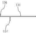
次に、第2実施形態に係るパネル状部材用の固定具について、図15~図19を用いて説明する。図15は、第2実施形態に係る固定具の側面図である。図16は、第2実施形態に係る固定具を構成する係合部材の上面図である。図17は、第2実施形態に係る固定具を構成する係合部材の側面図である。図18は、第2実施形態において、第1締結部材を緩めた状態で固定具をパネル状部材に取り付ける方法を説明する部分的拡大側面図である。図19は、図18に示す状態における第1締結部材と係合部材の位置関係を説明するための係合部材の上面図である。
[Second embodiment]
Next, a fixture for a panel-like member according to a second embodiment will be explained using FIGS. 15 to 19. FIG. 15 is a side view of the fixture according to the second embodiment. FIG. 16 is a top view of the engagement member that constitutes the fixture according to the second embodiment. FIG. 17 is a side view of an engagement member constituting the fixture according to the second embodiment. FIG. 18 is a partially enlarged side view illustrating a method of attaching the fixture to the panel-like member with the first fastening member loosened in the second embodiment. FIG. 19 is a top view of the engagement member for explaining the positional relationship between the first fastening member and the engagement member in the state shown in FIG. 18.

第2実施形態において、第1実施形態と同様の構成について同じ符号が付されていることに留意されたい。また、第2実施形態において、第1実施形態と同様の構成についてはその説明を省略することがある。 It should be noted that in the second embodiment, the same components as in the first embodiment are denoted by the same reference numerals. Furthermore, in the second embodiment, descriptions of configurations similar to those in the first embodiment may be omitted.

第2実施形態におけるパネル状部材10、支持部材110、締め具120、基部140、第1締結部材150、第2締結部材160及び第3締結部材170は、第1実施形態のものと同様である。 The panel-shapedmember 10,support member 110,fastener 120,base 140,first fastening member 150,second fastening member 160, andthird fastening member 170 in the second embodiment are the same as those in the first embodiment. .

第2実施形態における係合部材130は、第1実施形態と同様、支持部材110と締め具120との間に配置されていてよい。係合部材130は、第1締結部材150を挿通させる孔部132を有していてよい。孔部132の形状は、第1実施形態と同様であってよい(図16及び図19も参照)。係合部材130は、第1実施形態と同様、孔部132を挿通する第1締結部材150によって支持部材110に締結される。 Theengagement member 130 in the second embodiment may be arranged between thesupport member 110 and thefastener 120, as in the first embodiment. Theengagement member 130 may have ahole 132 through which thefirst fastening member 150 is inserted. The shape of thehole 132 may be similar to that of the first embodiment (see also FIGS. 16 and 19). Theengagement member 130 is fastened to thesupport member 110 by afirst fastening member 150 inserted through thehole 132, as in the first embodiment.

第2実施形態において、係合部材130の板部131は、パネル状部材10のフレーム14の底部に当接する(図15参照)。また、係合部材130は、板部131から上方に突出する第1突起136を有する。第1突起136は、パネル状部材10のフレーム14の底部の一端側に設けられている。具体的には、第1突起136は、板部131のうち、固定具100を仮止めすべきパネル状部材10側の端部に設けられていてよい。 In the second embodiment, theplate portion 131 of theengagement member 130 comes into contact with the bottom of theframe 14 of the panel-like member 10 (see FIG. 15). Furthermore, theengagement member 130 has afirst protrusion 136 that projects upward from theplate portion 131. Thefirst protrusion 136 is provided on one end side of the bottom of theframe 14 of the panel-like member 10. Specifically, thefirst protrusion 136 may be provided at the end of theplate portion 131 on the side of the panel-like member 10 to which thefixture 100 is to be temporarily fixed.

係合部材130の第1突起136は、支持部材110の積載部116上に積載されているパネル状部材10のフレーム14の底部14aよりも、締め具120に関して遠い位置に存在する。これにより、第1突起136は、パネル状部材10のフレーム14が締め具120から離れる方向にスライドすることを防止する。したがって、第1締結部材150が少し緩められた状態であっても、パネル状部材10の積載部116からの脱離が係合部材130の第1突起136によって防止される。 Thefirst protrusion 136 of theengagement member 130 is located further away from the bottom 14a of theframe 14 of thepanel member 10 loaded on theloading portion 116 of thesupport member 110 with respect to thefastener 120. Thereby, thefirst protrusion 136 prevents theframe 14 of the panel-like member 10 from sliding away from thefastener 120. Therefore, even if thefirst fastening member 150 is slightly loosened, thefirst protrusion 136 of theengagement member 130 prevents the panel-like member 10 from detaching from theloading portion 116.

第2実施形態において、係合部材130は、板部131から下方に突出する第2突起137を有していてよい。第2突起137は、支持部材110の壁面に当接していてよい。 In the second embodiment, theengagement member 130 may have asecond projection 137 that projects downward from theplate portion 131. Thesecond protrusion 137 may be in contact with the wall surface of thesupport member 110.

第2実施形態における固定具100をパネル状部材10の一辺に取り付ける方法について説明する。まず、第1締結部材150を緩めた状態で、係合部材130の第1突起136及び第2突起137を、締め具120から最も離れた位置に退避させた状態にする。この状態における固定具100が、図18に示されている。また、この状態において、係合部材150と第1締結部材150の相対的な位置関係が図19に示されている。この状態において、パネル状部材10のフレーム14の底部14aを、係合部材130の板部131上に置く(図18参照)。 A method of attaching thefixture 100 to one side of the panel-shapedmember 10 in the second embodiment will be described. First, with thefirst fastening member 150 loosened, thefirst protrusion 136 and thesecond protrusion 137 of theengagement member 130 are retracted to the farthest position from thefastener 120. Thefixture 100 in this state is shown in FIG. 18. Further, in this state, the relative positional relationship between the engagingmember 150 and thefirst fastening member 150 is shown in FIG. In this state, thebottom portion 14a of theframe 14 of the panel-like member 10 is placed on theplate portion 131 of the engagement member 130 (see FIG. 18).

次に、係合部材130を支持部材110及び締め具120に関してスライドさせる。より具体的には、係合部材130の第1突起136が第1締結部材150及び締め具120に近づくよう、係合部材130を列方向にスライドさせる。これにより、パネル状部材10は係合部材130とともに、支持部材110の積載部116と締め具120との間にスライドして挿入される。この際に、第2突起137は、支持部材110の壁面に当接する。 Next, theengagement member 130 is slid relative to thesupport member 110 and thefastener 120. More specifically, the engagingmember 130 is slid in the row direction so that thefirst protrusion 136 of the engagingmember 130 approaches thefirst fastening member 150 and thefastener 120. Thereby, the panel-shapedmember 10 is slid and inserted between theloading portion 116 of thesupport member 110 and thefastener 120 together with theengagement member 130. At this time, thesecond protrusion 137 comes into contact with the wall surface of thesupport member 110.

さらに、係合部材130を列方向に交差する方向にスライドさせることにより、係合部材130を、当該列方向にスライド不能な状態にする(図15及び図16参照)。これにより、第1締結部材150が緩められた状態であっても、係合部材130の列方向のスライドが規制されるため、係合部材130の第1突起136は、前述したようにパネル状部材10の脱離を防止し得る(仮止め状態)。 Furthermore, by sliding the engagingmember 130 in a direction that intersects the row direction, the engagingmember 130 is rendered non-slidable in the row direction (see FIGS. 15 and 16). As a result, even if thefirst fastening member 150 is in a loosened state, sliding of the engagingmember 130 in the column direction is restricted, so that thefirst protrusion 136 of the engagingmember 130 is shaped like a panel as described above. Themember 10 can be prevented from detaching (temporarily fixed state).

第1実施形態と同様に、第1締結部材150は、互いに隣接する一対のパネル状部材10が積載部116上に積載された後に強固に締結されればよい。これにより、一対のパネル状部材10は、支持部材110と締め具120の間で強固に支持される。 Similar to the first embodiment, thefirst fastening member 150 may be firmly fastened after a pair of mutually adjacent panel-like members 10 are loaded on theloading section 116. Thereby, the pair of panel-shapedmembers 10 are firmly supported between thesupport member 110 and thefastener 120.

第2実施形態における固定具100では、仮止めされるパネル状部材10を、係合部材130のスライドとともに容易に支持部材110の積載部116と締め具120との間に挿入することができる。 In thefixture 100 according to the second embodiment, the temporarily fixedpanel member 10 can be easily inserted between theloading portion 116 of thesupport member 110 and thefastener 120 as theengagement member 130 slides.

なお、第2実施形態における固定具100であっても、第1実施形態と同様の手順で、設置面90に複数のパネル状部材10を順番に設置することができる。 Note that even with thefixture 100 in the second embodiment, a plurality of panel-like members 10 can be sequentially installed on theinstallation surface 90 using the same procedure as in the first embodiment.

[第3実施形態]
次に、第3実施形態に係るパネル状部材用の固定具について、図20~図23を用いて説明する。図20は、第3実施形態に係る固定具の側面図である。図21は、第3実施形態において、第1締結部材を緩めた状態で固定具をパネル状部材に取り付ける方法を説明する部分的拡大側面図である。図22は、第3実施形態に係る固定具を構成する係合部材の上面図である。図23は、第3実施形態に係る固定具を構成する係合部材の側面図である。
[Third embodiment]
Next, a fixture for a panel-like member according to a third embodiment will be explained using FIGS. 20 to 23. FIG. 20 is a side view of the fixture according to the third embodiment. FIG. 21 is a partially enlarged side view illustrating a method of attaching the fixture to the panel-like member with the first fastening member loosened in the third embodiment. FIG. 22 is a top view of the engagement member that constitutes the fixture according to the third embodiment. FIG. 23 is a side view of an engagement member constituting the fixture according to the third embodiment.

第3実施形態において、第1実施形態及び/又は第2実施形態と同様の構成について同じ符号が付されていることに留意されたい。また、第3実施形態において、第1実施形態及び/又は第2実施形態と同様の構成についてはその説明を省略することがある。 It should be noted that in the third embodiment, the same components as in the first embodiment and/or the second embodiment are denoted by the same reference numerals. Further, in the third embodiment, descriptions of structures similar to those of the first embodiment and/or the second embodiment may be omitted.

第3実施形態における係合部材130は、第2実施形態と同様、板部131から上方に突出する第1突起136を有していてよい。第1突起136は、パネル状部材10のフレーム14の底部の一端側に設けられている。具体的には、第1突起136は、板部131のうち、固定具100を仮止めすべきパネル状部材10側の端部に設けられていてよい。 Theengagement member 130 in the third embodiment may have afirst protrusion 136 that projects upward from theplate portion 131, similar to the second embodiment. Thefirst protrusion 136 is provided on one end side of the bottom of theframe 14 of the panel-like member 10. Specifically, thefirst protrusion 136 may be provided at the end of theplate portion 131 on the side of the panel-like member 10 to which thefixture 100 is to be temporarily fixed.

係合部材130の第1突起136は、第2実施形態と同様に、第1締結部材150が少し緩められた状態であっても、パネル状部材10の積載部116からの脱離を防止する。 Similar to the second embodiment, thefirst protrusion 136 of theengagement member 130 prevents the panel-like member 10 from detaching from theloading section 116 even when thefirst fastening member 150 is slightly loosened. .

第3実施形態において、係合部材130は、支持部材110を把持する一対の第3突起138を有していてよい。係合部材130は、一対の第3突起138によって支持部材110を把持することによって、第1締結部材150が緩められた状態で、支持部材110に係合した状態を維持し得る。 In the third embodiment, theengagement member 130 may have a pair ofthird protrusions 138 that grip thesupport member 110. By gripping thesupport member 110 with the pair ofthird protrusions 138, theengagement member 130 can maintain the engaged state with thesupport member 110 while thefirst fastening member 150 is loosened.

具体的には、一対の第3突起138は、係合部材130の下方に向けて突出しており、一対のパネル状部材10が並ぶ列方向の両側で支持部材110を挟むよう構成されていてよい。これにより、係合部材130は、第1締結部材150が緩められた状態であっても、支持部材110に係合した状態を維持し得る。また、係合部材130は、一対の第3突起138により、互いに隣接するパネル状部材10が並ぶ列方向にスライド不能に構成されていてよい。すなわち、一対の第3突起138の両方が、支持部材110の側壁に当接していてよい。 Specifically, the pair ofthird protrusions 138 protrude downward from the engagingmember 130 and may be configured to sandwich thesupport member 110 on both sides in the row direction in which the pair of panel-like members 10 are lined up. . Thereby, theengagement member 130 can maintain a state of being engaged with thesupport member 110 even when thefirst fastening member 150 is in a loosened state. Moreover, theengagement member 130 may be configured to be non-slidable in the row direction in which the panel-like members 10 adjacent to each other are lined up by the pair ofthird protrusions 138 . That is, both of the pair ofthird protrusions 138 may be in contact with the side wall of thesupport member 110.

第3実施形態において、第1締結部材150は、係合部材130に形成された孔部132を挿通する。係合部材130に形成された孔部132は、緩めた第1締結部材150を傾斜可能なように列方向に延びていることが好ましい。具体的には、孔部132は、列方向において第1締結部材150の径よりも長い第3部分132cを有していてよい。同様に、支持部材110に形成された第3挿通孔117も、列方向において第1締結部材150の径よりも長くてよい。 In the third embodiment, thefirst fastening member 150 is inserted through ahole 132 formed in theengagement member 130. Preferably, thehole 132 formed in theengagement member 130 extends in the row direction so that the loosenedfirst fastening member 150 can be tilted. Specifically, thehole 132 may have athird portion 132c that is longer than the diameter of thefirst fastening member 150 in the column direction. Similarly, thethird insertion hole 117 formed in thesupport member 110 may also be longer than the diameter of thefirst fastening member 150 in the column direction.

これにより、第1締結部材150が緩められると、第1締結部材150は、締め具120とともに傾く(図21参照)。この状態において、第1支持部材110の積載部116及び係合部材130上に、パネル状部材10を容易に置くことができる。 Accordingly, when thefirst fastening member 150 is loosened, thefirst fastening member 150 tilts together with the fastener 120 (see FIG. 21). In this state, thepanel member 10 can be easily placed on theloading portion 116 and theengagement member 130 of thefirst support member 110.

孔部132は、第3部分132cに連通し、列方向に交差する方向に延びた第4部分132dを有していてもよい。第4部分132dの幅は、第1締結部材150の径と同程度であってよい。この場合、係合部材130を列方向に交差する方向にスライドし、第1締結部材150が第4部分132dに位置することによって、第1締結部材150は、直立した姿勢を維持することもできる。 Thehole 132 may have afourth portion 132d that communicates with thethird portion 132c and extends in a direction intersecting the column direction. The width of thefourth portion 132d may be approximately the same as the diameter of thefirst fastening member 150. In this case, thefirst fastening member 150 can also maintain an upright posture by sliding the engagingmember 130 in a direction crossing the row direction and positioning thefirst fastening member 150 in thefourth portion 132d. .

パネル状部材10が第1支持部材110の積載部116及び係合部材130上に置かれた後に、係合部材130をスライドさせて第1締結部材150が第4部分132dに位置することによって、第1締結部材150は、直立した状態となる。この状態において、パネル状部材10のフレーム14は、締め具120と支持部材110との間に挟まれた状態になる。この状態において、第1突起136は、パネル状部材10のフレーム14が積載部116から脱離することを防止することができる。 After the panel-like member 10 is placed on theloading portion 116 of thefirst support member 110 and theengagement member 130, theengagement member 130 is slid so that thefirst fastening member 150 is located in thefourth portion 132d. Thefirst fastening member 150 is in an upright state. In this state, theframe 14 of thepanel member 10 is sandwiched between thefastener 120 and thesupport member 110. In this state, thefirst protrusion 136 can prevent theframe 14 of the panel-like member 10 from detaching from theloading section 116.

第1締結部材150を十分に傾斜させることができるように、収容スペースS1は、十分に大きいことが好ましい。第1締結部材150がボルト及びナットにより構成される場合、収容スペースS1は、第1締結部材150を構成するナットを十分に傾斜させることができる大きさを有していてよい。 It is preferable that the accommodation space S1 is sufficiently large so that thefirst fastening member 150 can be sufficiently inclined. When thefirst fastening member 150 is composed of a bolt and a nut, the accommodation space S1 may have a size that allows the nut constituting thefirst fastening member 150 to be sufficiently inclined.

第1締結部材150を十分に傾斜させることができるように、締め具120は、前述した突出部124を有していなくてもよい。この場合、第1締結部材150が十分に締結された状態であっても、締め具120の底部は、支持部材110に当接しなくてよい。 Thefastener 120 does not need to have theprotrusion 124 described above so that thefirst fastening member 150 can be sufficiently inclined. In this case, even if thefirst fastening member 150 is fully fastened, the bottom of thefastener 120 does not need to come into contact with thesupport member 110.

第1実施形態及び第2実施形態と同様に、第1締結部材150は、互いに隣接する一対のパネル状部材10が積載部116上に積載された後に強固に締結されればよい。これにより、一対のパネル状部材10は、支持部材110と締め具120の間で強固に支持される。 Similar to the first embodiment and the second embodiment, thefirst fastening member 150 may be firmly fastened after a pair of mutually adjacent panel-like members 10 are loaded on theloading section 116. Thereby, the pair of panel-shapedmembers 10 are firmly supported between thesupport member 110 and thefastener 120.

第3実施形態における固定具100では、係合部材130は、支持部材110に関してスライドする必要がない。そのため、係合部材130は、支持部材110に関してスライド不能に固定されてもよい。 In thefixture 100 in the third embodiment, theengagement member 130 does not need to slide with respect to thesupport member 110. Therefore, theengagement member 130 may be non-slidably fixed with respect to thesupport member 110.

第3実施形態における固定具100であっても、第1実施形態と同様の手順で、設置面90に複数のパネル状部材10を順番に設置することができる。 Even with thefixture 100 in the third embodiment, a plurality of panel-like members 10 can be installed in order on theinstallation surface 90 using the same procedure as in the first embodiment.

[第4実施形態]
次に、第4実施形態に係るパネル状部材用の固定具について、図24~図25を用いて説明する。図24は、第4実施形態に係る固定具の側面図である。図25は、第4実施形態に係る固定具の締め具を取り外した状態を示す側面図である。
[Fourth embodiment]
Next, a fixture for a panel-shaped member according to a fourth embodiment will be explained using FIGS. 24 to 25. FIG. 24 is a side view of the fixture according to the fourth embodiment. FIG. 25 is a side view of the fixture according to the fourth embodiment with the fastener removed.

第4実施形態において、第1実施形態、第2実施形態及び/又は第3実施形態と同様の構成について同じ符号が付されていることに留意されたい。また、第4実施形態において、第1実施形態、第2実施形態及び/又は第3実施形態と同様の構成についてはその説明を省略することがある。 It should be noted that in the fourth embodiment, the same components as those in the first embodiment, the second embodiment, and/or the third embodiment are denoted by the same reference numerals. Further, in the fourth embodiment, descriptions of structures similar to those of the first embodiment, the second embodiment, and/or the third embodiment may be omitted.

第4実施形態における係合部材130は、第1実施形態と同様の挟持部134を有していてよい。ただし、係合部材130は、支持部材110と締め具120との間に位置していない。 Theengagement member 130 in the fourth embodiment may have thesame clamping part 134 as in the first embodiment. However, theengagement member 130 is not located between thesupport member 110 and thefastener 120.

第4実施形態では、係合部材130は、支持部材110に関して移動不能に固定する固定部139を有する。固定部139は、支持部材110の側壁に当接する板部を有し、第4締結部材180によって支持部材110に締結されていてよい。すなわち、係合部材130は、支持部材110に直接固定されていてよい。 In the fourth embodiment, theengagement member 130 has a fixingpart 139 that fixes it immovably with respect to thesupport member 110. The fixingpart 139 has a plate part that comes into contact with the side wall of thesupport member 110 and may be fastened to thesupport member 110 by afourth fastening member 180. That is, theengagement member 130 may be directly fixed to thesupport member 110.

第4締結部材180は、特に制限されないが、例えば釘のように、その製造後に取り外すことを意図しない部材によって構成されていてよい。第4締結部材180による固定位置は、支持部材110の側壁のうち、仮止めされるパネル状部材10によって覆われる部分であってよい。 Thefourth fastening member 180 is not particularly limited, but may be made of a member that is not intended to be removed after manufacturing, such as a nail, for example. The fixed position by thefourth fastening member 180 may be a portion of the side wall of thesupport member 110 that is covered by thepanel member 10 that is temporarily fixed.

第4実施形態では、締め具120が取り外されたとしても、係合部材130は、支持部材100に固定されている。さらに、係合部材130の挟持部134がパネル状部材10のフレーム14を挟持している。したがって、第1締結部材が取り外された状態、より具体的には締め具120が取り外された状態であったとしても、係合部材130は、パネル状部材10の、支持部材110の積載部116からの脱離を防止することができる。 In the fourth embodiment, theengagement member 130 is fixed to thesupport member 100 even if thefastener 120 is removed. Furthermore, the clampingportion 134 of the engagingmember 130 clamps theframe 14 of the panel-shapedmember 10. Therefore, even if the first fastening member is removed, and more specifically, thefastener 120 is removed, theengagement member 130 is still attached to theloading portion 116 of thesupport member 110 of the panel-like member 10. It is possible to prevent detachment from the molecule.

第4実施形態では、パネル状部材10及び係合部材130が支持部材110の積載部116上に固定された後に、第1締結部材150によって締め具130を支持部材110に取り付ければよい。この場合であっても、第1締結部材150は、パネル状部材10の施工前には、緩められた状態で仮止めされることが好ましい。 In the fourth embodiment, thefastener 130 may be attached to thesupport member 110 by thefirst fastening member 150 after the panel-like member 10 and theengagement member 130 are fixed on theloading portion 116 of thesupport member 110. Even in this case, it is preferable that thefirst fastening member 150 be temporarily fastened in a loosened state before the panel-shapedmember 10 is installed.

第4実施形態では、支持部材110や締め具120として、既存の構成のものを利用することもできる。すなわち、既存の支持部材110や締め具120に対して、前述した係合部材130を第4締結部材180で固定することによって、パネル状部材10の仮止めが可能になる。 In the fourth embodiment, existing configurations can also be used as thesupport member 110 and thefastener 120. That is, by fixing the aforementioned engagingmember 130 to the existingsupport member 110 andfastener 120 using thefourth fastening member 180, the panel-like member 10 can be temporarily fixed.

第1実施形態、第2実施形態及び第3実施形態と同様に、第1締結部材150は、互いに隣接する一対のパネル状部材10が積載部116上に積載された後に強固に締結されればよい。これにより、一対のパネル状部材10は、支持部材110と締め具120の間で強固に支持される。 Similarly to the first embodiment, the second embodiment, and the third embodiment, thefirst fastening member 150 is firmly fastened after a pair of mutually adjacent panel-like members 10 are loaded on theloading section 116. good. Thereby, the pair of panel-shapedmembers 10 are firmly supported between thesupport member 110 and thefastener 120.

第4実施形態における固定具100であっても、第1実施形態と同様の手順で、設置面90に複数のパネル状部材10を順番に設置することができる。 Even with thefixture 100 in the fourth embodiment, a plurality of panel-like members 10 can be sequentially installed on theinstallation surface 90 using the same procedure as in the first embodiment.

上述したように、実施形態を通じて本発明の内容を開示したが、この開示の一部をなす論述及び図面は、本発明を限定するものであると理解すべきではない。この開示から当業者には様々な代替の実施形態、実施例及び運用技術が明らかとなる。したがって、本発明の技術的範囲は、上述の説明から妥当な特許請求の範囲に係る発明特定事項によってのみ定められるものである。 As described above, the content of the present invention has been disclosed through the embodiments, but the statements and drawings that form part of this disclosure should not be understood as limiting the present invention. Various alternative embodiments, implementations, and operational techniques will be apparent to those skilled in the art from this disclosure. Therefore, the technical scope of the present invention is determined only by the matters specifying the invention in the claims that are reasonable from the above description.

例えば、上記の複数の実施形態及び/又は実施例で説明した各構成及び特徴は、可能な限り、他の実施形態及び/又は実施例に適用又は交換可能であることに留意されたい。 For example, it should be noted that each configuration and feature described in the plurality of embodiments and/or examples above can be applied or replaced with other embodiments and/or examples to the extent possible.

また、前述したすべての実施形態において、固定具100は、支持部材110とは別個に基部140を有する。この代わりに、固定具100は、基部140を有していなくてもよい。この場合、支持部材110は、設置面90に直接固定されてもよい。 Additionally, in all of the embodiments described above, thefixture 100 has a base 140 separate from thesupport member 110. Alternatively,fixture 100 may not havebase 140. In this case, thesupport member 110 may be directly fixed to theinstallation surface 90.

10 パネル状部材
90 設置面
100 固定具
110 支持部材
116 積載部
120 締め具
129 フランジ
130 係合部材
132 孔部
132a 第1部分
132b 第2部分
134 挟持部
136 第1突起
138 第3突起
150 第1締結部材

10 Panel-shapedmember 90Installation surface 100Fixing tool 110 Supportingmember 116Loading section 120Fastener 129Flange 130Engagement member 132Hole 132aFirst portion 132bSecond portion 134Holding portion 136First protrusion 138Third protrusion 150 First Fastening member

Claims (14)

Translated fromJapanese
互いに隣接する一対のパネル状部材を積載可能な積載部を有する支持部材と、
前記積載部上に積載させた前記一対のパネル状部材を前記積載部に向けて押圧可能な締め具と、
前記支持部材に前記締め具を締結する第1締結部材と、
前記第1締結部材を緩めた状態又は前記第1締結部材を取り外した状態で、前記一対のパネル状部材のうちの一方の前記積載部からの脱離を防止する係合部材と、を有する、パネル状部材用の固定具。
a support member having a loading section capable of loading a pair of mutually adjacent panel-like members;
a fastener capable of pressing the pair of panel-shaped members loaded on the loading section toward the loading section;
a first fastening member that fastens the fastener to the support member;
an engaging member that prevents one of the pair of panel-shaped members from detaching from the loading section when the first fastening member is loosened or the first fastening member is removed; Fixing device for panel-shaped members.
前記係合部材は、前記支持部材と前記締め具との間に配置されており、前記第1締結部材を挿通させる孔部を有する、請求項1に記載のパネル状部材用の固定具。 The fixture for a panel-shaped member according to claim 1, wherein the engagement member is disposed between the support member and the fastener, and has a hole through which the first fastening member is inserted. 前記係合部材は、前記第1締結部材を緩めた状態又は前記第1締結部材を取り外した状態で、前記一対のパネル状部材が並ぶ列方向にスライド可能に構成されている、請求項1又は2に記載のパネル状部材用の固定具。 2. The engaging member is configured to be slidable in a row direction in which the pair of panel-shaped members are arranged in a state where the first fastening member is loosened or removed. 2. A fixture for a panel-shaped member according to item 2. 前記係合部材は、前記列方向にスライド可能な第1状態と、前記列方向にスライド不能な第2状態との間で可変に構成されている、請求項3に記載のパネル状部材用の固定具。 4. The panel member according to claim 3, wherein the engaging member is configured to be variably configured between a first state in which it is slidable in the column direction and a second state in which it is not slidable in the column direction. Fixture. 前記係合部材は、前記第1締結部材を挿通させる孔部を有し、
前記孔部は、
前記一対のパネル状部材が並ぶ列方向に延びた第1部分と、
前記第1部分に繋がっており、前記列方向から交差する方向に延びた第2部分と、を有する、請求項1から4のいずれか1項に記載のパネル状部材用の固定具。
The engagement member has a hole through which the first fastening member is inserted,
The hole is
a first portion extending in the row direction in which the pair of panel-shaped members are lined up;
The fixture for a panel-shaped member according to any one of claims 1 to 4, further comprising a second part connected to the first part and extending in a direction crossing the column direction.
前記係合部材は、前記支持部材を把持する一対の第3突起を有する、請求項1又は2に記載のパネル状部材用の固定具。 The fixture for a panel-shaped member according to claim 1 or 2, wherein the engagement member has a pair of third protrusions that grip the support member. 前記一対の第3突起は、前記係合部材の下方に向けて突出しており、前記一対のパネル状部材が並ぶ列方向の両側で前記支持部材を挟むよう構成されている、請求項6に記載のパネル状部材用の固定具。 7. The pair of third protrusions protrude downward from the engagement member, and are configured to sandwich the support member on both sides in the row direction in which the pair of panel-like members are lined up. Fixtures for panel-shaped members. 前記係合部材は、前記第1締結部材を挿通させる孔部を有し、
前記孔部は、緩めた前記第1締結部材を傾斜可能なように前記列方向に延びている、請求項6又は7に記載のパネル状部材用の固定具。
The engagement member has a hole through which the first fastening member is inserted,
The fixture for a panel-shaped member according to claim 6 or 7, wherein the hole extends in the row direction so that the loosened first fastening member can be tilted.
前記係合部材は、前記支持部材に関して移動不能に固定する固定部を有する、請求項1から8のいずれか1項に記載のパネル状部材用の固定具。 The fixture for a panel-like member according to any one of claims 1 to 8, wherein the engagement member has a fixing part that fixes the engagement member immovably with respect to the support member. 前記固定部は、前記支持部材の側壁に当接する板部を有し、第4締結部材によって前記支持部材に締結されている、請求項9に記載のパネル状部材用の固定具。 The fixing device for a panel-shaped member according to claim 9, wherein the fixing part has a plate part that comes into contact with a side wall of the support member, and is fastened to the support member by a fourth fastening member. 前記係合部材は、前記パネル状部材のフレームの底部を挟持可能な挟持部を有する、請求項1から10のいずれか1項に記載のパネル状部材用の固定具。 The fixture for a panel-shaped member according to any one of claims 1 to 10, wherein the engaging member has a clamping part that can clamp the bottom of the frame of the panel-shaped member. 前記係合部材は、前記パネル状部材のフレームの底部に当接する板部と、
前記フレームの底部の一端側に設けられ、前記板部から上方に突出する第1突起と、を有する、請求項1から10のいずれか1項に記載のパネル状部材用の固定具。
The engagement member includes a plate portion that comes into contact with the bottom of the frame of the panel-like member;
The fixture for a panel-like member according to any one of claims 1 to 10, further comprising a first protrusion provided at one end of the bottom of the frame and protruding upward from the plate.
請求項1から12のいずれか1項に記載のパネル状部材用の固定具と、
パネル状部材と、を有し、
前記固定具が、前記パネル状部材の一辺に係合している、パネル状部材組立体。
A fixture for a panel-shaped member according to any one of claims 1 to 12,
A panel-shaped member;
A panel-like member assembly, wherein the fixture engages one side of the panel-like member.
請求項13に記載のパネル状部材組立体を複数準備するステップと、
一の前記パネル状部材組立体を構成する前記パネル状部材の前記一辺に係合している前記固定具を設置面に固定するステップと、
別の前記パネル状部材組立体を構成する前記パネル状部材の、前記固定具が係合していない一辺を、前記設置面に固定した前記固定具の前記積載部に積載させるステップと、を有する、パネル状部材の設置方法。

preparing a plurality of panel-like member assemblies according to claim 13;
fixing the fixing tool, which is engaged with the one side of the panel-shaped member constituting one of the panel-shaped member assemblies, to an installation surface;
loading one side of the panel-like member constituting another of the panel-like member assemblies that is not engaged with the fixture onto the loading portion of the fixture fixed to the installation surface; , How to install panel-shaped members.

JP2022054356A2022-03-292022-03-29Fixture for panel-shape member, panel-shape member assembly and installation method of panel-shape memberPendingJP2023146918A (en)

Priority Applications (1)

Application NumberPriority DateFiling DateTitle
JP2022054356AJP2023146918A (en)2022-03-292022-03-29Fixture for panel-shape member, panel-shape member assembly and installation method of panel-shape member

Applications Claiming Priority (1)

Application NumberPriority DateFiling DateTitle
JP2022054356AJP2023146918A (en)2022-03-292022-03-29Fixture for panel-shape member, panel-shape member assembly and installation method of panel-shape member

Publications (1)

Publication NumberPublication Date
JP2023146918Atrue JP2023146918A (en)2023-10-12

Family

ID=88286627

Family Applications (1)

Application NumberTitlePriority DateFiling Date
JP2022054356APendingJP2023146918A (en)2022-03-292022-03-29Fixture for panel-shape member, panel-shape member assembly and installation method of panel-shape member

Country Status (1)

CountryLink
JP (1)JP2023146918A (en)

Citations (10)

* Cited by examiner, † Cited by third party
Publication numberPriority datePublication dateAssigneeTitle
JPS58126655U (en)*1982-02-221983-08-27日本軽金属株式会社 Solar collector mounting device
JP2004060358A (en)*2002-07-312004-02-26Kyocera Corp Roof fixing device and solar energy utilization structure using the same
JP2011084919A (en)*2009-10-142011-04-28Ryoju Estate Co LtdSolar light utilization system, frame for installing solar battery panel, and method of installing solar battery panel
JPWO2010024154A1 (en)*2008-08-292012-01-26シャープ株式会社 Solar cell module mounting structure and solar cell device
JP2012188927A (en)*2012-06-292012-10-04Sharp CorpPhotovoltaic generation system
JP3184365U (en)*2012-05-282013-06-27シァメン グレイス ソーラー テクノロジー カンパニー,リミテッド Easy to dismantle solar panel bracket structure
JP2013159971A (en)*2012-02-062013-08-19Yuki Steel Co LtdMounting bracket of solar panel
US20150020873A1 (en)*2011-12-022015-01-22Cooper Technologies CompanyModule rail for a photovoltaic system
JP2018162575A (en)*2017-03-242018-10-18パナソニック株式会社 Photovoltaic generator stand
JP2020041384A (en)*2018-09-132020-03-19ソーラーフロンティア株式会社Fixture for solar cell module and structure for fixing solar cell module

Patent Citations (10)

* Cited by examiner, † Cited by third party
Publication numberPriority datePublication dateAssigneeTitle
JPS58126655U (en)*1982-02-221983-08-27日本軽金属株式会社 Solar collector mounting device
JP2004060358A (en)*2002-07-312004-02-26Kyocera Corp Roof fixing device and solar energy utilization structure using the same
JPWO2010024154A1 (en)*2008-08-292012-01-26シャープ株式会社 Solar cell module mounting structure and solar cell device
JP2011084919A (en)*2009-10-142011-04-28Ryoju Estate Co LtdSolar light utilization system, frame for installing solar battery panel, and method of installing solar battery panel
US20150020873A1 (en)*2011-12-022015-01-22Cooper Technologies CompanyModule rail for a photovoltaic system
JP2013159971A (en)*2012-02-062013-08-19Yuki Steel Co LtdMounting bracket of solar panel
JP3184365U (en)*2012-05-282013-06-27シァメン グレイス ソーラー テクノロジー カンパニー,リミテッド Easy to dismantle solar panel bracket structure
JP2012188927A (en)*2012-06-292012-10-04Sharp CorpPhotovoltaic generation system
JP2018162575A (en)*2017-03-242018-10-18パナソニック株式会社 Photovoltaic generator stand
JP2020041384A (en)*2018-09-132020-03-19ソーラーフロンティア株式会社Fixture for solar cell module and structure for fixing solar cell module

Similar Documents

PublicationPublication DateTitle
CN103782510B (en) Pivot fit framework, system and method for photovoltaic modules
JP4290750B2 (en) Solar cell module fixing structure, solar cell module frame and fixing member
JP5468664B2 (en) Solar cell module mounting structure and solar cell device
US20100077679A1 (en)Structure installation stand
JP5936068B2 (en) Mounting bracket for solar cell module and construction method
CN103221622A (en)Solar battery module fixture
JP2003035016A (en)Shape material fixing structure and installation rack for photovoltaic power generation using the same
JP6558632B2 (en) Solar power plant
JPH08296311A (en) Solar cell module roof installation tool and solar cell module roof installation method
US10298170B2 (en)Photovoltaic mounting system
JP2017110451A (en)Support metal fittings for solar battery panel
WO2012121147A1 (en)Mounting base for solar cell module, method for constructing mounting base, and solar photovoltaic power generation system with mounting base
JPWO2016175319A1 (en) Solar cell module
JP2023146918A (en)Fixture for panel-shape member, panel-shape member assembly and installation method of panel-shape member
KR102377186B1 (en)Solar module fastener
JP5308194B2 (en) Structure support and solar cell module system using the same
JP7384557B2 (en) Mount for solar power generation panel, solar power generation device, and installation method of solar power generation device
JP5686771B2 (en) Solar cell module fixing structure and solar cell module fixing method
JP3934453B2 (en) Roof structure with solar panel
CN217159595U (en)Photovoltaic module structure
JP3252620U (en) Solar module mounting structure
JP6851733B2 (en) Panel array mounting structure and panel array mounting method
JP6749798B2 (en) Fixture for panel array
CN119109412B (en)Photovoltaic panel butt joint device and method for photovoltaic construction
JP7161311B2 (en) Panel mounting structures, fixtures for panels, and fixture installation methods

Legal Events

DateCodeTitleDescription
A621Written request for application examination

Free format text:JAPANESE INTERMEDIATE CODE: A621

Effective date:20240619

A977Report on retrieval

Free format text:JAPANESE INTERMEDIATE CODE: A971007

Effective date:20241030

A131Notification of reasons for refusal

Free format text:JAPANESE INTERMEDIATE CODE: A131

Effective date:20241119

A02Decision of refusal

Free format text:JAPANESE INTERMEDIATE CODE: A02

Effective date:20250408


[8]ページ先頭

©2009-2025 Movatter.jp