Movatterモバイル変換


[0]ホーム

URL:


JP2023144742A - Catheter for diagnostic imaging - Google Patents

Catheter for diagnostic imaging
Download PDF

Info

Publication number
JP2023144742A
JP2023144742AJP2022051867AJP2022051867AJP2023144742AJP 2023144742 AJP2023144742 AJP 2023144742AJP 2022051867 AJP2022051867 AJP 2022051867AJP 2022051867 AJP2022051867 AJP 2022051867AJP 2023144742 AJP2023144742 AJP 2023144742A
Authority
JP
Japan
Prior art keywords
optical element
receiver
catheter
optical
transmitter
Prior art date
Legal status (The legal status is an assumption and is not a legal conclusion. Google has not performed a legal analysis and makes no representation as to the accuracy of the status listed.)
Pending
Application number
JP2022051867A
Other languages
Japanese (ja)
Inventor
圭史 橋本
Keiji Hashimoto
Current Assignee (The listed assignees may be inaccurate. Google has not performed a legal analysis and makes no representation or warranty as to the accuracy of the list.)
Terumo Corp
Original Assignee
Terumo Corp
Priority date (The priority date is an assumption and is not a legal conclusion. Google has not performed a legal analysis and makes no representation as to the accuracy of the date listed.)
Filing date
Publication date
Application filed by Terumo CorpfiledCriticalTerumo Corp
Priority to JP2022051867ApriorityCriticalpatent/JP2023144742A/en
Publication of JP2023144742ApublicationCriticalpatent/JP2023144742A/en
Pendinglegal-statusCriticalCurrent

Links

Images

Landscapes

Abstract

To provide a catheter for diagnostic imaging which, even when an optical element of a light transmission and reception part is disposed at a position where an air trap is apt to occur, makes it easy to execute handling to suppress occurrence of an air trap.SOLUTION: The catheter for diagnostic imaging, which is configured for acquiring a tomographic image of a body cavity, comprises a long-sized sheath, a shaft disposed within the sheath, and an imaging core fixed to the distal end of the shaft. The imaging core comprises the light transmission and reception part with an optical element, an ultrasonic transmission and reception part, and a holding part capable of holding a light transmission member having flowability before hardening, at a position of covering the optical element of the light transmission and reception part.SELECTED DRAWING: Figure 4

Description

Translated fromJapanese

本開示は画像診断用カテーテルに関する。 The present disclosure relates to catheters for diagnostic imaging.

従来から、動脈硬化の診断、血管内治療時の術前診断、等を目的として画像診断装置が広く使用されている。画像診断装置には、血管内超音波診断装置(IVUS:Intra Vascular Ultra Sound)や光干渉断層診断装置(OCT:Optical Coherence Tomography、又は、OFDI:Optical Frequency Domain Imaging)等が含まれ、それぞれに異なる特性を有している。 2. Description of the Related Art Image diagnostic apparatuses have been widely used for the purpose of diagnosing arteriosclerosis, preoperative diagnosis during endovascular treatment, and the like. Diagnostic imaging devices include intravascular ultrasound (IVUS), optical coherence tomography (OCT), or optical frequency domain imaging (OFDI). ging), etc., and each is different. It has characteristics.

更に、最近では、IVUSの機能と、OCT/OFDIの機能と、を組み合わせた画像診断装置も提案されている(例えば、特許文献1、2参照)。この種の画像診断装置では、体腔に挿入されるシース内に、IVUS用の超音波送受信部と、OCT/OFDI用の光送受信部と、を備える、画像診断用カテーテルが用いられる。 Furthermore, recently, image diagnostic apparatuses that combine IVUS functions and OCT/OFDI functions have been proposed (for example, seePatent Documents 1 and 2). This type of image diagnostic apparatus uses an image diagnostic catheter that includes an ultrasound transmitting/receiving section for IVUS and an optical transmitting/receiving section for OCT/OFDI in a sheath inserted into a body cavity.

特開平11-56752号公報Japanese Patent Application Publication No. 11-56752特表2010-508973号公報Special Publication No. 2010-508973

超音波送受信部及び光送受信部を備える画像診断用カテーテルでは、超音波送受信部と空気との界面での超音波の反射を抑制するため、シース内を予めプライミング液により満たすプライミング処理が必要となる。プライミング処理の際に、シース内に空気が残留する場合がある。例えば光送受信部の光学素子が凹部内に配置される場合等、画像診断用カテーテルの光送受信部が配置される位置によっては、この空気が気泡としてシース内の光送受信部の光学素子を覆う位置に滞留し易い(エアトラップが発生し易い)場合がある。気泡が光送受信部の光学素子を覆う位置で滞留すると、光干渉断層画像のノイズとなり、病変部の正確な画像が得られない可能性がある。 Diagnostic imaging catheters equipped with an ultrasound transmitter/receiver and an optical transmitter/receiver require a priming process in which the sheath is filled with priming liquid in advance to suppress reflection of ultrasound at the interface between the ultrasound transmitter/receiver and air. . Air may remain inside the sheath during the priming process. For example, if the optical element of the optical transmitter/receiver is placed in a recess, depending on the position where the optical transmitter/receiver of the diagnostic imaging catheter is placed, this air may form a bubble and cover the optical element of the optical transmitter/receiver within the sheath. may easily accumulate in the air (air traps may easily occur). If air bubbles remain at a position covering the optical element of the optical transmitter/receiver, noise will occur in the optical coherence tomographic image, and there is a possibility that an accurate image of the lesion cannot be obtained.

本開示は、エアトラップが発生し易い位置に光送受信部の光学素子が配置される場合であっても、エアトラップの発生を抑制する対応を容易に実行可能な、画像診断用カテーテルを提供することを目的とする。 The present disclosure provides an imaging diagnostic catheter that can easily take measures to suppress the occurrence of air traps even when an optical element of an optical transmitter/receiver is placed in a position where air traps are likely to occur. The purpose is to

本開示の第1の態様としての画像診断用カテーテルは、体腔の断層画像を取得するための画像診断用カテーテルであって、長尺状のシースと、前記シース内に配置されるシャフトと、前記シャフトの遠位端部に固定されているイメージングコアと、を備え、前記イメージングコアは、光学素子を備える光送受信部と、超音波送受信部と、前記光送受信部の前記光学素子を覆う位置に硬化前の流動性を有する状態の光透過部材を保持可能な保持部と、を備える。 An image diagnostic catheter according to a first aspect of the present disclosure is an image diagnostic catheter for acquiring a tomographic image of a body cavity, and includes an elongated sheath, a shaft disposed within the sheath, and a shaft disposed within the sheath. an imaging core fixed to a distal end of the shaft, the imaging core being located at a position covering an optical transmitting/receiving section including an optical element, an ultrasound transmitting/receiving section, and the optical element of the optical transmitting/receiving section. A holding portion capable of holding the light transmitting member in a fluid state before curing.

本開示の1つの実施形態として、前記イメージングコアは、前記光送受信部及び前記超音波送受信部を支持するハウジングを備え、前記保持部は、前記ハウジングのうち前記光送受信部の前記光学素子を覆う位置に形成されている貫通孔である。 In one embodiment of the present disclosure, the imaging core includes a housing that supports the optical transmitting and receiving unit and the ultrasound transmitting and receiving unit, and the holding unit covers the optical element of the optical transmitting and receiving unit in the housing. This is a through hole formed in the position.

本開示の1つの実施形態として、前記イメージングコアは、前記光送受信部の前記光学素子より近位側に、X線造影性を有する造影マーカ部材を備え、前記造影マーカ部材には、前記光送受信部の前記光学素子に接続される導光部材が挿通される挿通孔が形成されている。 In one embodiment of the present disclosure, the imaging core includes a contrast marker member having X-ray contrast property on a proximal side of the optical element of the optical transmitter/receiver, and the contrast marker member includes a contrast marker member that has an X-ray contrast property. An insertion hole is formed through which a light guide member connected to the optical element of the portion is inserted.

本開示の1つの実施形態として、前記イメージングコアは、前記光送受信部の前記光学素子を覆うように配置され、X線造影性を有する造影マーカ部材を備え、前記保持部は、前記造影マーカ部材の前記光送受信部の前記光学素子を覆う位置に形成されている貫通孔である。 In one embodiment of the present disclosure, the imaging core includes a contrast marker member that is arranged to cover the optical element of the optical transmitter/receiver and has X-ray contrast properties, and the holding portion is configured to The through hole is formed at a position covering the optical element of the optical transmitter/receiver.

本開示の1つの実施形態として、前記イメージングコアは、前記光送受信部及び前記超音波送受信部を支持するハウジングを備え、前記造影マーカ部材は、前記ハウジングに支持されている。 In one embodiment of the present disclosure, the imaging core includes a housing that supports the optical transmitter/receiver and the ultrasound transmitter/receiver, and the contrast marker member is supported by the housing.

本開示の1つの実施形態として、前記超音波送受信部は、前記光送受信部の前記光学素子より遠位側に位置し、前記造影マーカ部材には、前記超音波送受信部に接続されている電気信号線が挿通される挿通孔が形成されている。 In one embodiment of the present disclosure, the ultrasound transmitting and receiving section is located distally from the optical element of the optical transmitting and receiving section, and the contrast marker member includes an electric light connected to the ultrasound transmitting and receiving section. An insertion hole is formed through which the signal line is inserted.

本開示の1つの実施形態として、前記光送受信部の前記光学素子は、ボールレンズである。 In one embodiment of the present disclosure, the optical element of the optical transmitter/receiver is a ball lens.

本開示の1つの実施形態として、前記イメージングコアは、前記保持部に保持される前記光透過部材を備える。 As one embodiment of the present disclosure, the imaging core includes the light transmitting member held by the holding section.

本開示によれば、エアトラップが発生し易い位置に光送受信部の光学素子が配置される場合であっても、エアトラップの発生を抑制する対応を容易に実行可能な、画像診断用カテーテルを提供することができる。 According to the present disclosure, there is provided a catheter for image diagnosis that can easily take measures to suppress the occurrence of air traps even when the optical element of the optical transmitter/receiver is placed in a position where air traps are likely to occur. can be provided.

本開示の一実施形態としての画像診断用カテーテル、を備える画像診断装置を示す図である。1 is a diagram showing an image diagnostic apparatus including an image diagnostic catheter as an embodiment of the present disclosure.図1に示す画像診断用カテーテルを示す図であり、内管が外管内に最も押し込まれた押し込み状態を示す図である。FIG. 2 is a diagram illustrating the diagnostic imaging catheter shown in FIG. 1 in a pushed-in state in which the inner tube is pushed the most into the outer tube.図1に示す画像診断用カテーテルを示す図であり、内管が外管から最も引き出された引き出し状態を示す図である。FIG. 2 is a diagram illustrating the diagnostic imaging catheter shown in FIG. 1, and is a diagram illustrating a pulled-out state in which the inner tube is pulled out the most from the outer tube.図1に示す画像診断用カテーテルの遠位端部を示す図である。FIG. 2 is a diagram showing a distal end portion of the diagnostic imaging catheter shown in FIG. 1. FIG.図1に示す画像診断用カテーテルのイメージングコアの斜視図である。FIG. 2 is a perspective view of the imaging core of the diagnostic imaging catheter shown in FIG. 1. FIG.図1に示す画像診断用カテーテルのイメージングコアの上面図である。FIG. 2 is a top view of the imaging core of the diagnostic imaging catheter shown in FIG. 1. FIG.図3~図5に示す保持部の変形例として保持部を備える画像診断用カテーテルの遠位端部を示す図である。FIG. 6 is a diagram showing a distal end portion of an imaging diagnostic catheter including a holding portion as a modification of the holding portion shown in FIGS. 3 to 5. FIG.図6に示す画像診断用カテーテルのイメージングコアの上面図である。7 is a top view of the imaging core of the diagnostic imaging catheter shown in FIG. 6. FIG.図7のI-I線の位置での断面図である。8 is a cross-sectional view taken along the line I-I in FIG. 7. FIG.

以下、本開示に係る画像診断用カテーテルの実施形態について図面を参照して例示説明する。各図において同一の構成には同一の符号を付している。 DESCRIPTION OF THE PREFERRED EMBODIMENTS Hereinafter, embodiments of a catheter for diagnostic imaging according to the present disclosure will be described by way of example with reference to the drawings. In each figure, the same components are given the same reference numerals.

以下、本開示では、画像診断用カテーテルの長手方向を「長手方向A」と記載する。本開示では、画像診断用カテーテルの長手方向Aで生体内に挿入される側を「遠位側」と記載する。画像診断用カテーテルの長手方向Aで生体外にて操作される手元側を「近位側」と記載する。画像診断用カテーテルの近位側から遠位側に向かう方向を単に「挿入方向A1」と記載する場合がある。画像診断用カテーテルの遠位端側から近位端側に向かう方向を単に「抜去方向A2」と記載する場合がある。 Hereinafter, in the present disclosure, the longitudinal direction of the catheter for image diagnosis will be referred to as "longitudinal direction A." In the present disclosure, the side of the imaging diagnostic catheter inserted into the living body in the longitudinal direction A is referred to as the "distal side." The proximal side that is operated outside the living body in the longitudinal direction A of the diagnostic imaging catheter is referred to as the "proximal side." The direction from the proximal side to the distal side of the diagnostic imaging catheter may be simply referred to as "insertion direction A1." The direction from the distal end to the proximal end of the diagnostic imaging catheter may be simply referred to as "removal direction A2."

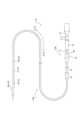
まず、本開示に係る画像診断用カテーテルの一実施形態としての画像診断用カテーテル110、を備える画像診断装置100について説明する。図1は、画像診断装置100を示す図である。画像診断装置100は、画像診断用カテーテル110と、外部装置120と、を備える。図1では、画像診断用カテーテル110が外部装置120に接続されている状態を示している。 First, an imagediagnostic apparatus 100 including an imagediagnostic catheter 110 as an embodiment of an image diagnostic catheter according to the present disclosure will be described. FIG. 1 is a diagram showing an imagediagnostic apparatus 100. Theimage diagnosis apparatus 100 includes animage diagnosis catheter 110 and anexternal device 120. FIG. 1 shows a state in which thediagnostic imaging catheter 110 is connected to anexternal device 120.

<画像診断用カテーテル110>
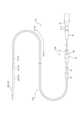
図2A、図2Bは、図1に示す画像診断用カテーテル110単体を示す図である。詳細は後述するが、図2A、図2Bは、シース20内でのプローブ10の長手方向Aの位置が異なる状態を示している。図3は、画像診断用カテーテル110の遠位側の端部(以下、「遠位端部」と記載する。)を示す図である。画像診断用カテーテル110は、体腔の断層画像を取得可能に構成されている。より具体的に、画像診断用カテーテル110は、IVUS用の超音波送受信部61a及びOCT/OFDI用の光送受信部61bと、を備える。図1に示すように、画像診断用カテーテル110は、外部装置120に接続されることによって駆動される。より具体的に、本実施形態の画像診断用カテーテル110は、外部装置120の駆動ユニット120aに接続されている。
<Image diagnosis catheter 110>
2A and 2B are diagrams showing thediagnostic imaging catheter 110 shown in FIG. 1 alone. Although details will be described later, FIGS. 2A and 2B show states in which the position of theprobe 10 in the longitudinal direction A within thesheath 20 is different. FIG. 3 is a diagram showing the distal end (hereinafter referred to as "distal end") of thediagnostic imaging catheter 110. Thediagnostic imaging catheter 110 is configured to be capable of acquiring tomographic images of body cavities. More specifically, thediagnostic imaging catheter 110 includes an ultrasound transmitting/receivingsection 61a for IVUS and an optical transmitting/receivingsection 61b for OCT/OFDI. As shown in FIG. 1, thediagnostic imaging catheter 110 is driven by being connected to anexternal device 120. More specifically, thediagnostic imaging catheter 110 of this embodiment is connected to adrive unit 120a of anexternal device 120.

図1~図3に示すように、画像診断用カテーテル110は、挿入部110aと、操作部110bと、を備える。挿入部110aは、画像診断用カテーテル110のうち、生体内の血管等の体腔に挿入されて使用される部位である。操作部110bは、画像診断用カテーテル110のうち、挿入部110aが体腔に挿入されている状態で、生体外で操作される部位である。本実施形態の画像診断用カテーテル110では、後述する遠位側コネクタ42よりも遠位側の部分が挿入部110aであり、遠位側コネクタ42から近位側の部分が操作部110bである。 As shown in FIGS. 1 to 3, thediagnostic imaging catheter 110 includes aninsertion section 110a and anoperation section 110b. Theinsertion section 110a is a part of thediagnostic imaging catheter 110 that is used by being inserted into a body cavity such as a blood vessel in a living body. Theoperating section 110b is a part of thediagnostic imaging catheter 110 that is operated outside the living body while theinsertion section 110a is inserted into a body cavity. In thediagnostic imaging catheter 110 of this embodiment, a portion distal to adistal connector 42 to be described later is aninsertion portion 110a, and a portion proximal to thedistal connector 42 is an operatingportion 110b.

図1~図3に示すように、挿入部110aは、プローブ10の遠位側の部分と、シース20と、を備える。本実施形態において、挿入部110aに含まれるプローブ10の遠位側の部分とは、超音波送受信部61aと、光送受信部61bと、シャフト13の遠位側の部分と、電気信号線14aの遠位側の部分と、導光部材14bの遠位側の部分と、で構成されている。 As shown in FIGS. 1 to 3, theinsertion section 110a includes a distal portion of theprobe 10 and asheath 20. In the present embodiment, the distal portion of theprobe 10 included in theinsertion portion 110a includes the ultrasonic transmitter/receiver 61a, the optical transmitter/receiver 61b, the distal portion of theshaft 13, and theelectrical signal line 14a. It is composed of a distal side portion and a distal side portion of thelight guide member 14b.

操作部110bは、シャフト13をシース20内でシース20の長手方向(長手方向Aと同じ方向)に移動させることができる。図1~図3に示すように、操作部110bは、プローブ10の近位側の部分と、内管30と、外管40と、を備える。本実施形態において、操作部110bに含まれるプローブ10の近位側の部分とは、シャフト13の近位側の部分と、電気信号線14aの近位側の部分と、導光部材14bの近位側の部分と、で構成されている。 Theoperating section 110b can move theshaft 13 within thesheath 20 in the longitudinal direction of the sheath 20 (the same direction as the longitudinal direction A). As shown in FIGS. 1 to 3, theoperating section 110b includes a proximal portion of theprobe 10, aninner tube 30, and anouter tube 40. In this embodiment, the proximal portion of theprobe 10 included in theoperating section 110b includes the proximal portion of theshaft 13, the proximal portion of theelectrical signal line 14a, and the proximal portion of thelight guide member 14b. It consists of the position side part and.

内管30は、プローブ10の近位側の端部(以下、「近位側の端部」を単に「近位端部」と記載する。)を保持している。外管40は、シース20の近位端部を保持している。詳細は後述するが、内管30が外管40内を中心軸方向(長手方向Aと同じ方向)に移動することで、プローブ10がシース20内を長手方向Aに移動することができる。図2Aは、内管30が外管40内に向かって遠位側に最も押し込まれた押し込み状態を示している。図2Bは、内管30が外管40から近位側に最も引き出された引き出し状態を示している。 Theinner tube 30 holds a proximal end (hereinafter, the "proximal end" is simply referred to as "proximal end") of theprobe 10.Outer tube 40 holds the proximal end ofsheath 20. Although details will be described later, theprobe 10 can move within thesheath 20 in the longitudinal direction A by moving theinner tube 30 in the central axis direction (the same direction as the longitudinal direction A) within theouter tube 40. FIG. 2A shows a pushed-in state in which theinner tube 30 is pushed most distally into theouter tube 40. FIG. 2B shows a pulled-out state in which theinner tube 30 is pulled out most proximally from theouter tube 40.

図1~図3に示すように、本実施形態の画像診断用カテーテル110は、プローブ10と、長尺状のシース20と、内管30と、外管40と、を備える。以下、本実施形態の画像診断用カテーテル110の各部について詳細に説明する。 As shown in FIGS. 1 to 3, thediagnostic imaging catheter 110 of this embodiment includes aprobe 10, along sheath 20, aninner tube 30, and anouter tube 40. Each part of thediagnostic imaging catheter 110 of this embodiment will be described in detail below.

[プローブ10]
図3に示すように、プローブ10は、イメージングコア60と、シャフト13と、このシャフト13内を延在する電気信号線14a及び導光部材14bと、を備える。本実施形態のイメージングコア60は、超音波送受信部61aと、光送受信部61bと、造影マーカ部材61cと、ハウジング61dと、先端部材61eと、光透過部材Xと、を備える。
[Probe 10]
As shown in FIG. 3, theprobe 10 includes animaging core 60, ashaft 13, and anelectric signal line 14a and alight guide member 14b extending inside theshaft 13. Theimaging core 60 of this embodiment includes an ultrasound transmitting/receivingsection 61a, a light transmitting/receivingsection 61b, acontrast marker member 61c, ahousing 61d, atip member 61e, and a light transmitting member X.

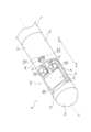
図4は、イメージングコア60の斜視図である。図5は、イメージングコア60の上面図である。図4、図5では、説明の便宜上、貫通孔61d2に保持される光透過部材Xを図示省略している。図3~図5に示すように、イメージングコア60は、シャフト13の遠位端部に固定されている。本実施形態のイメージングコア60の超音波送受信部61aは、超音波振動子62を備える。超音波振動子62は、パルス信号に基づく超音波を体腔内に送信し、かつ、体腔内の生体組織から反射してきた超音波を受信可能である。本実施形態の超音波振動子62は、本体部62aと、電極62bと、を備える。本体部62aは、圧電素子を含む。圧電素子は、例えばセラミックス、水晶などの圧電体を含む。超音波送受信部61aは、超音波振動子62により、超音波の送受信を行うことができる。超音波送受信部61aは、光送受信部61bの後述する光学素子61b1より遠位側に位置している。 FIG. 4 is a perspective view of theimaging core 60. FIG. 5 is a top view of theimaging core 60. In FIGS. 4 and 5, for convenience of explanation, the light transmitting member X held in the through hole 61d2 is omitted. As shown in FIGS. 3 to 5, theimaging core 60 is fixed to the distal end of theshaft 13. As shown in FIGS. Theultrasonic transceiver 61a of theimaging core 60 of this embodiment includes anultrasonic transducer 62. Theultrasonic transducer 62 is capable of transmitting ultrasonic waves based on pulse signals into the body cavity and receiving ultrasonic waves reflected from living tissue within the body cavity. Theultrasonic transducer 62 of this embodiment includes amain body 62a and anelectrode 62b. Themain body portion 62a includes a piezoelectric element. The piezoelectric element includes, for example, a piezoelectric material such as ceramics or crystal. Theultrasonic transceiver 61a can transmit and receive ultrasonic waves using theultrasonic transducer 62. The ultrasonic transmitter/receiver 61a is located on the distal side of the optical element 61b1, which will be described later, of the optical transmitter/receiver 61b.

光送受信部61bは、伝送された光を連続的に体腔内に送信するとともに、体腔内の生体組織において反射した光を連続的に受信可能である。光送受信部61bは、光学素子61b1を備える。光学素子61b1は、導光部材14bの遠位端部に接続され、光を集光するレンズ機能と反射する反射機能とを備える。 The optical transmitter/receiver 61b is capable of continuously transmitting the transmitted light into the body cavity and continuously receiving the light reflected from the living tissue within the body cavity. The optical transmitter/receiver 61b includes an optical element 61b1. The optical element 61b1 is connected to the distal end of thelight guide member 14b, and has a lens function for condensing light and a reflection function for reflecting light.

本実施形態の光学素子61b1は、長手方向Aに対して傾斜する平面部65aと、球面部65bと、を備えるボーズレンズである。平面部65aには、導光部材14bから伝播する光を反射する反射コートが施されている。反射コートの構成材料は、光を反射可能である限り特に限定されないが、例えば、アルミニウム等が挙げられる。導光部材14bから伝播する光は平面部65aにおいて反射し、球面部65bにおいて集光され、体腔内に送信される。体腔内の生体組織において反射した光は、球面部65bにおいて集光され、平面部65aにおいて反射し導光部材14bに伝播される。このようにして、光送受信部61bは、光学素子61b1を通じて、光の送受信を行うことができる。 The optical element 61b1 of this embodiment is a Bose lens including aflat portion 65a inclined with respect to the longitudinal direction A and aspherical portion 65b. A reflective coating that reflects the light propagating from thelight guide member 14b is applied to theplane portion 65a. The material constituting the reflective coat is not particularly limited as long as it can reflect light, and examples thereof include aluminum. The light propagating from thelight guide member 14b is reflected at theflat section 65a, collected at thespherical section 65b, and transmitted into the body cavity. The light reflected from the living tissue in the body cavity is collected at thespherical section 65b, reflected at theflat section 65a, and propagated to thelight guide member 14b. In this way, the optical transmitter/receiver 61b can transmit and receive light through the optical element 61b1.

造影マーカ部材61cは、X線造影性を有する。具体的に、造影マーカ部材61cは、X線不透過性の高い材料で形成されている。具体的には、造影マーカ部材61cは、例えば、白金、金、イリジウム、タングステン等のX線不透過性の高い材料により構成可能である。 Thecontrast marker member 61c has X-ray contrast properties. Specifically, thecontrast marker member 61c is made of a material with high X-ray opacity. Specifically, thecontrast marker member 61c can be made of a material with high X-ray opacity, such as platinum, gold, iridium, and tungsten.

図3に示すように、造影マーカ部材61cには、導光部材14bが長手方向Aに挿通される挿通孔61c1、及び、電気信号線14aが長手方向Aに挿通される挿通孔61c2、が形成されている。 As shown in FIG. 3, thecontrast marker member 61c has an insertion hole 61c1 through which thelight guide member 14b is inserted in the longitudinal direction A, and an insertion hole 61c2 through which theelectric signal line 14a is inserted in the longitudinal direction A. has been done.

本実施形態の造影マーカ部材61cは、光送受信部61bの光学素子61b1に対して近位側に配置されている。本実施形態の造影マーカ部材61cは、ハウジング61dに固定されている。より具体的に、本実施形態の造影マーカ部材61cは、ハウジング61dの後述する近位筒部12b内で、ハウジング61dに固定されている。導光部材14bは、ハウジング61dに固定されている造影マーカ部材61cの挿通孔61c1に挿通された状態で支持される。これにより、導光部材14bに接続されている光送受信部61bは、ハウジング61d内で位置決めされている。 Thecontrast marker member 61c of this embodiment is arranged on the proximal side with respect to the optical element 61b1 of the optical transmitting/receivingsection 61b. Thecontrast marker member 61c of this embodiment is fixed to thehousing 61d. More specifically, thecontrast marker member 61c of this embodiment is fixed to thehousing 61d within aproximal tube portion 12b of thehousing 61d, which will be described later. Thelight guide member 14b is supported while being inserted into the insertion hole 61c1 of thecontrast marker member 61c fixed to thehousing 61d. Thereby, the optical transmitter/receiver 61b connected to thelight guide member 14b is positioned within thehousing 61d.

ハウジング61dは、超音波送受信部61a、光送受信部61b及び造影マーカ部材61cを直接的又は間接的に支持している。ハウジング61dの近位側は、シャフト13に接続されている。ハウジング61dは、シャフト13と一体化されていればよい。したがって、ハウジング61dは、シャフト13に接着等により直接的に接続されていてもよく、シャフト13にコネクタ等を介して間接的に接続されていてもよい。 Thehousing 61d directly or indirectly supports the ultrasound transmitter/receiver 61a, the optical transmitter/receiver 61b, and thecontrast marker member 61c. The proximal side of thehousing 61d is connected to theshaft 13. Thehousing 61d only needs to be integrated with theshaft 13. Therefore, thehousing 61d may be directly connected to theshaft 13 by adhesive or the like, or may be indirectly connected to theshaft 13 via a connector or the like.

図4、図5に示すように、本実施形態のハウジング61dは、遠位筒部12aと、近位筒部12bと、支持板部12cと、を備える。 As shown in FIGS. 4 and 5, thehousing 61d of this embodiment includes adistal tube portion 12a, aproximal tube portion 12b, and asupport plate portion 12c.

遠位筒部12aは、ハウジング61dの遠位端部を構成している。遠位筒部12aは、超音波送受信部61a及び光送受信部61bより遠位側に位置している。近位筒部12bは、ハウジング61dの近位端部を構成している。本実施形態の近位筒部12bは、超音波送受信部61aより近位側に位置している。また、本実施形態の近位筒部12bは、光送受信部61bの光学素子61b1の周囲を覆っている。詳細は後述するが、近位筒部12bには、光学素子61b1を覆う位置に、保持部70としての貫通孔61d2が形成されている。より具体的に、本実施形態の貫通孔61d2は、光学素子61b1としてのボールレンズの球面部65bを覆う位置に形成されている。支持板部12cは、遠位筒部12aの周壁と、近位筒部12bの周壁と、に連なる湾曲板部である。換言すれば、本実施形態のハウジング61dは筒状体であり、この筒状体の周壁の一部が切り欠かれて形成された窓部61d1を備える。超音波送受信部61aは、この窓部61d1を通じて、パルス信号に基づく超音波を体腔内に送信可能である。また、超音波送受信部61aは、この窓部61d1を通じて、体腔内の生体組織から反射してきた超音波を受信可能である。 Thedistal tube portion 12a constitutes the distal end portion of thehousing 61d. Thedistal tube portion 12a is located on the distal side of the ultrasonic transmitter/receiver 61a and the optical transmitter/receiver 61b. Theproximal tube portion 12b constitutes the proximal end portion of thehousing 61d. Theproximal tube portion 12b of this embodiment is located on the proximal side of the ultrasound transmitting/receivingsection 61a. Further, theproximal tube portion 12b of this embodiment covers the optical element 61b1 of the optical transmitting/receivingsection 61b. Although details will be described later, a through hole 61d2 serving as a holdingportion 70 is formed in theproximal cylinder portion 12b at a position covering the optical element 61b1. More specifically, the through hole 61d2 of this embodiment is formed at a position that covers thespherical portion 65b of the ball lens serving as the optical element 61b1. Thesupport plate portion 12c is a curved plate portion continuous with the peripheral wall of thedistal cylinder portion 12a and the peripheral wall of theproximal cylinder portion 12b. In other words, thehousing 61d of this embodiment is a cylindrical body, and includes a window portion 61d1 formed by cutting out a part of the peripheral wall of the cylindrical body. The ultrasonic transmitter/receiver 61a can transmit ultrasonic waves based on pulse signals into the body cavity through the window 61d1. Further, the ultrasonic wave transmitting/receivingunit 61a can receive ultrasonic waves reflected from living tissue within the body cavity through the window portion 61d1.

支持板部12cは、バッキング部材80を介して、超音波送受信部61aを支持している。バッキング部材80は、超音波送受信部61aからハウジング61dの窓部61d1の反対方向へ向かう超音波を散乱減衰させる。バッキング部材80を支持板部12cに固定する方法は特に限定されない。バッキング部材80は、例えば、接着剤による接着によって支持板部12cに固定されてよい。本実施形態のバッキング部材80は、超音波送受信部61aが長手方向Aに対して傾斜した方向に超音波を送信できるように超音波送受信部61aを支持している。 Thesupport plate section 12c supports the ultrasonic transmitter/receiver section 61a via the backingmember 80. The backingmember 80 scatters and attenuates the ultrasonic waves traveling from the ultrasonic transmitter/receiver 61a in a direction opposite to the window 61d1 of thehousing 61d. The method of fixing the backingmember 80 to thesupport plate portion 12c is not particularly limited. The backingmember 80 may be fixed to thesupport plate portion 12c by, for example, adhesive bonding. The backingmember 80 of this embodiment supports the ultrasonic transmitter/receiver 61a so that the ultrasonic transmitter/receiver 61a can transmit ultrasound in a direction inclined with respect to the longitudinal direction A.

ハウジング61dは、例えば、金属塊からの削りだしやMIM(金属粉末射出成形)等により形成されてよい。 Thehousing 61d may be formed by, for example, machining from a metal block, MIM (metal powder injection molding), or the like.

先端部材61eは、ハウジング61dの遠位側に固定されている。先端部材61eは略半球状の外形を有する。先端部材61eを設けることで、シース20の内面との摩擦や引っ掛かりを抑制できる。本実施形態の先端部材61eは、例えば、コイルによって構成されてもよい。また、先端部材61eは、ハウジング61dと一体で形成されてもよい。更に、イメージングコア60は、先端部材61eを備えなくてもよい。 Thetip member 61e is fixed to the distal side of thehousing 61d. Thetip member 61e has a substantially hemispherical outer shape. By providing thetip member 61e, it is possible to suppress friction and catching with the inner surface of thesheath 20. Thetip member 61e of this embodiment may be configured by, for example, a coil. Moreover, thetip member 61e may be formed integrally with thehousing 61d. Furthermore, theimaging core 60 does not need to include thetip member 61e.

光透過部材Xは、光送受信部61bの光学素子61b1を覆う位置に配置されている。本実施形態の光透過部材Xは、ハウジング61dのうち光学素子61b1を覆う位置に形成されている貫通孔61d2内に保持されている。上述したように、図4、図5では、説明の便宜上、貫通孔61d2に保持される光透過部材Xを図示省略している。光透過部材Xは、プライミング液と略等しい絶対屈折率を有する材料により構成可能である。このようにすることで、光透過部材Xが光学素子61b1を覆っていても、光透過部材Xが光学素子61b1を覆っていない構成と同等の分解能で、光干渉断層画像を生成できる。 The light transmitting member X is arranged at a position covering the optical element 61b1 of the optical transmitter/receiver 61b. The light transmitting member X of this embodiment is held in a through hole 61d2 formed in thehousing 61d at a position covering the optical element 61b1. As described above, in FIGS. 4 and 5, for convenience of explanation, the light transmitting member X held in the through hole 61d2 is not shown. The light transmitting member X can be made of a material having an absolute refractive index substantially equal to that of the priming liquid. In this way, even if the light-transmitting member X covers the optical element 61b1, an optical coherence tomographic image can be generated with the same resolution as a configuration in which the light-transmitting member X does not cover the optical element 61b1.

光透過部材Xは、流動性を有する状態から、各種方法を用いることで硬化可能な材料、で構成される。光透過部材Xを硬化させるための各種方法は特に限定されないが、例えば、熱硬化、UV硬化等が挙げられる。光透過部材Xは、例えば、接着剤であってよい。 The light transmitting member X is made of a material that can be cured from a fluid state by using various methods. Various methods for curing the light transmitting member X are not particularly limited, and examples thereof include thermal curing, UV curing, and the like. The light transmitting member X may be, for example, an adhesive.

光透過部材Xは、硬化前の流動性を有する状態で、貫通孔61d2に充填される。そして、貫通孔61d2は、硬化前の流動性を有する状態の光透過部材Xを保持可能に構成されている。この詳細は後述する。 The light transmitting member X is filled into the through hole 61d2 in a fluid state before being cured. The through hole 61d2 is configured to be able to hold the light transmitting member X in a fluid state before curing. The details will be described later.

図2A、図2B、図3に示すように、シャフト13は、シース20内に配置されている。シャフト13は、可撓性を有する管体により構成されている。図3に示すように、シャフト13の内部には、イメージングコア60の超音波送受信部61aに接続される電気信号線14aが配置されている。また、図3に示すように、シャフト13の内部には、イメージングコア60の光送受信部61bに接続される導光部材14bが配置されている。シャフト13は、例えば、軸まわりの巻き方向が異なる多層のコイルによって構成されてよい。本実施形態のシャフト13は、3層のコイルにより構成されている。コイルの材料としては、例えば、ステンレス、Ni-Ti(ニッケル・チタン)合金等が挙げられる。 As shown in FIGS. 2A, 2B, and 3, theshaft 13 is disposed within thesheath 20. Theshaft 13 is made of a flexible tube. As shown in FIG. 3, anelectric signal line 14a connected to the ultrasound transmitting/receivingsection 61a of theimaging core 60 is arranged inside theshaft 13. Further, as shown in FIG. 3, alight guiding member 14b connected to the optical transmitting/receivingsection 61b of theimaging core 60 is arranged inside theshaft 13. Theshaft 13 may be configured by, for example, a multilayer coil having different winding directions around the axis. Theshaft 13 of this embodiment is composed of three layers of coils. Examples of the material of the coil include stainless steel and Ni-Ti (nickel-titanium) alloy.

図2A、図2B、図3に示すように、シャフト13は、シース20、内管30及び外管40の内部を通って延在している。上述したように、シャフト13の遠位端部は、イメージングコア60のハウジング61dに接続されている。シャフト13の近位端は、内管30の近位端を構成する後述のハブ32に保持されている。つまり、シャフト13は、長手方向Aにおいて、挿入部110aの遠位端部から操作部110bの近位端部まで延在している。 As shown in FIGS. 2A, 2B, and 3, theshaft 13 extends through thesheath 20, theinner tube 30, and theouter tube 40. As mentioned above, the distal end of theshaft 13 is connected to thehousing 61d of theimaging core 60. The proximal end of theshaft 13 is held by ahub 32, which will be described later, and which constitutes the proximal end of theinner tube 30. That is, theshaft 13 extends in the longitudinal direction A from the distal end of theinsertion section 110a to the proximal end of theoperating section 110b.

図3に示すように、電気信号線14aは、シャフト13内に延在している。電気信号線14aは、イメージングコア60の超音波送受信部61aと外部装置120(図1参照)とを電気的に接続している。つまり、電気信号線14aは、シャフト13と同様、長手方向Aにおいて、挿入部110aの遠位端部から操作部110bの近位端部まで延在している。電気信号線14aは複数(本実施形態では2本)設けられており、図4、図5に示すように、各電気信号線14aは、イメージングコア60の超音波送受信部61aの電極62bに接続されている。複数の電気信号線14aは、例えば、2本の電気信号線14aが撚り合わされたツイストペアケーブルにより構成されてよい。各電気信号線14aは、外径が0mmより大きく0.1mm以下の、可撓性を有する柔軟な細線部材とすることができる。各電気信号線14aは、例えば、導線と、絶縁材料により形成され、導線の周囲を被覆する被覆材と、により構成可能である。 As shown in FIG. 3, theelectric signal line 14a extends inside theshaft 13. Theelectrical signal line 14a electrically connects the ultrasound transmitting/receivingsection 61a of theimaging core 60 and the external device 120 (see FIG. 1). That is, like theshaft 13, theelectric signal line 14a extends in the longitudinal direction A from the distal end of theinsertion section 110a to the proximal end of theoperating section 110b. A plurality ofelectrical signal lines 14a (two in this embodiment) are provided, and as shown in FIGS. has been done. The plurality ofelectrical signal lines 14a may be configured by, for example, a twisted pair cable in which twoelectrical signal lines 14a are twisted together. Eachelectric signal line 14a can be a flexible thin wire member with an outer diameter of greater than 0 mm and less than or equal to 0.1 mm. Eachelectric signal line 14a can be configured of, for example, a conducting wire and a covering material made of an insulating material and covering the periphery of the conducting wire.

図3に示すように、導光部材14bは、シャフト13内に延在している。導光部材14bは、イメージングコア60の光送受信部61bと外部装置120(図1参照)とを光学的に接続している。つまり、導光部材14bは、シャフト13と同様、長手方向Aにおいて、挿入部110aの遠位端部から操作部110bの近位端部まで延在している。図3に示すように、導光部材14bは、イメージングコア60の光送受信部61bの光学素子61b1に接続されている。導光部材14bは、例えば、光ファイバである。 As shown in FIG. 3, thelight guide member 14b extends within theshaft 13. Thelight guide member 14b optically connects the optical transmitting/receivingsection 61b of theimaging core 60 and the external device 120 (see FIG. 1). That is, like theshaft 13, thelight guide member 14b extends in the longitudinal direction A from the distal end of theinsertion section 110a to the proximal end of theoperating section 110b. As shown in FIG. 3, thelight guiding member 14b is connected to the optical element 61b1 of the optical transmitting/receivingsection 61b of theimaging core 60. Thelight guide member 14b is, for example, an optical fiber.

[シース20]
シース20は、血管等の体腔内に挿入される長尺状の部材である。図2A、図2B、図3に示すように、シース20は、本体部20aと、ガイドワイヤ挿通部20bと、を備える。本体部20aの内部には、第1中空部21aが区画されている。ガイドワイヤ挿通部20bには、第2中空部21bが区画されている。本体部20aの第1中空部21aには、プローブ10が収容されている。プローブ10は、第1中空部21aにおいて、長手方向Aに進退移動することができる。ガイドワイヤ挿通部20bの第2中空部21bには、ガイドワイヤWが挿通可能である。図3に示すように、ガイドワイヤ挿通部20bには、X線造影性を有する造影マーカ部23が設けられてよい。造影マーカ部23は、例えば、白金、金、イリジウム、タングステン等のX線不透過性の高い金属パイプ又は金属コイルにより構成可能である。また、図3に示すように、本実施形態では、管状のガイドワイヤ挿通部20bが、管状の本体部20aの遠位端部に対して、互いが平行な状態になるように隣接されている。本体部20a及びガイドワイヤ挿通部20bは、互いに異なる管部材を熱融着等によって接合することで形成されてよい。
[Sheath 20]
Thesheath 20 is a long member inserted into a body cavity such as a blood vessel. As shown in FIGS. 2A, 2B, and 3, thesheath 20 includes amain body portion 20a and a guidewire insertion portion 20b. A firsthollow portion 21a is defined inside themain body portion 20a. A secondhollow portion 21b is defined in the guidewire insertion portion 20b. Theprobe 10 is accommodated in the firsthollow portion 21a of themain body portion 20a. Theprobe 10 can move forward and backward in the longitudinal direction A in the firsthollow portion 21a. The guide wire W can be inserted into the secondhollow portion 21b of the guidewire insertion portion 20b. As shown in FIG. 3, the guidewire insertion portion 20b may be provided with acontrast marker portion 23 having X-ray contrast properties. Thecontrast marker section 23 can be constructed of a metal pipe or metal coil with high X-ray opacity, such as platinum, gold, iridium, tungsten, or the like. Further, as shown in FIG. 3, in this embodiment, the tubular guidewire insertion portion 20b is adjacent to the distal end portion of the tubularmain body portion 20a so that they are parallel to each other. . Themain body portion 20a and the guidewire insertion portion 20b may be formed by joining different tube members together by heat fusion or the like.

また、本実施形態の本体部20aの遠位端部には、第1中空部21aの内部と外部とを連通する連通孔22a1が形成されている。また、本体部20aの遠位端部には、ガイドワイヤ挿通部20bを強固に接合・支持するための補強部材22が設けられる。補強部材22には、補強部材22より基端側に配置される第1中空部21aの内部と連通孔22a1とを連通する連通路22aが形成されている。但し、本体部20aの遠位端部には、補強部材22が設けられていなくてもよい。 Furthermore, a communication hole 22a1 is formed in the distal end portion of themain body portion 20a of this embodiment, which communicates the inside and outside of the firsthollow portion 21a. Further, a reinforcingmember 22 for firmly joining and supporting the guidewire insertion portion 20b is provided at the distal end portion of themain body portion 20a. The reinforcingmember 22 is formed with acommunication passage 22a that communicates the inside of the firsthollow portion 21a disposed on the proximal side of the reinforcingmember 22 with the communication hole 22a1. However, the reinforcingmember 22 may not be provided at the distal end of themain body 20a.

連通孔22a1は、プライミング液を排出するためのプライミング液排出孔である。画像診断用カテーテル110を使用する際は、プライミング液をシース20の本体部20a内に充填させるプライミング処理を行う。例えば、シース20の本体部20a内にプライミング液を充填させないまま、超音波を送信させた場合、超音波送受信部61aの超音波振動子62の本体部62aの表面に配置される整合層および空気の音響インピーダンスの差が大きいことに起因して、整合層と空気の界面で超音波が反射し易い。これに対して、整合層と音響インピーダンスの値が近いプライミング液をシース20の本体部20a内に充填させることで、上述の反射を抑制できる。プライミング処理を行う際に、プライミング液を連通孔22a1から外部に放出させて、プライミング液とともに空気等の気体をシース20の本体部20a内から排出することができる。 The communication hole 22a1 is a priming liquid discharge hole for discharging the priming liquid. When using thediagnostic imaging catheter 110, a priming process is performed in which themain body 20a of thesheath 20 is filled with a priming liquid. For example, if ultrasound is transmitted without filling themain body 20a of thesheath 20 with the priming liquid, the matching layer and the air Due to the large difference in acoustic impedance between the two layers, ultrasonic waves are likely to be reflected at the interface between the matching layer and the air. On the other hand, by filling themain body portion 20a of thesheath 20 with a priming liquid whose acoustic impedance value is similar to that of the matching layer, the above-mentioned reflection can be suppressed. When performing the priming process, the priming liquid can be discharged to the outside from the communication hole 22a1, and gas such as air can be discharged from themain body portion 20a of thesheath 20 together with the priming liquid.

シース20及び補強部材22は、可撓性を有する材料で形成されることが好ましいが、その材料は特に限定されない。構成材料としては、例えば、スチレン系、ポリオレフィン系、ポリウレタン系、ポリエステル系、ポリアミド系、ポリイミド系、ポリブタジエン系、トランスポリイソプレン系、フッ素ゴム系、塩素化ポリエチレン系等の各種熱可塑性エラストマー等が挙げられ、これらのうちの1種または2種以上を組合せたもの(ポリマーアロイ、ポリマーブレンド、積層体等)も用いることができる。また、シース20の外表面には、湿潤時に潤滑性を示す親水性潤滑被覆層を配置してもよい。 Thesheath 20 and the reinforcingmember 22 are preferably made of a flexible material, but the material is not particularly limited. Examples of the constituent materials include various thermoplastic elastomers such as styrene, polyolefin, polyurethane, polyester, polyamide, polyimide, polybutadiene, transpolyisoprene, fluororubber, and chlorinated polyethylene. One or a combination of two or more of these (polymer alloy, polymer blend, laminate, etc.) can also be used. Furthermore, a hydrophilic lubricating coating layer that exhibits lubricity when wet may be disposed on the outer surface of thesheath 20.

[内管30及び外管40]
内管30は、シャフト13の近位端部を収容し、シャフト13と共に外管40内を移動可能である。図1、図2A、図2Bに示すように、内管30は、内管本体31と、ハブ32と、を備える。内管本体31は、外管40内で進退移動可能に挿入されている。ハブ32は、内管本体31の近位側に接続されている。
[Inner tube 30 and outer tube 40]
Inner tube 30 accommodates the proximal end ofshaft 13 and is movable withshaft 13 withinouter tube 40 . As shown in FIGS. 1, 2A, and 2B, theinner tube 30 includes an inner tubemain body 31 and ahub 32. The inner tubemain body 31 is inserted into theouter tube 40 so as to be movable forward and backward. Thehub 32 is connected to the proximal side of theinner tube body 31.

図1、図2A、図2Bに示すように、外管40は、シース20の近位端部に固定されている。本実施形態の外管40は、外管本体41と、遠位側コネクタ42と、近位側コネクタ43と、を備える。外管本体41は、内管本体31の径方向外側に位置し、外管本体41内を内管本体31が進退移動する。遠位側コネクタ42は、シース20の本体部20aの近位端部と、外管本体41の遠位端部と、を接続している。近位側コネクタ43は、外管本体41の近位端部に固定されている。 As shown in FIGS. 1, 2A, and 2B, theouter tube 40 is fixed to the proximal end of thesheath 20. Theouter tube 40 of this embodiment includes an outer tubemain body 41, adistal connector 42, and aproximal connector 43. Theouter tube body 41 is located on the radially outer side of theinner tube body 31, and theinner tube body 31 moves forward and backward within theouter tube body 41. Thedistal connector 42 connects the proximal end of themain body 20a of thesheath 20 and the distal end of the outer tubemain body 41. Theproximal connector 43 is fixed to the proximal end of theouter tube body 41.

上述したプローブ10のシャフト13、電気信号線14a及び導光部材14bは、シース20の本体部20aから、この本体部20aの近位側に接続された外管40を通じて、内管30の近位端を構成するハブ32まで、延在している。 Theshaft 13, theelectric signal line 14a, and thelight guide member 14b of theprobe 10 described above are passed from themain body 20a of thesheath 20 to the proximal side of theinner tube 30 through theouter tube 40 connected to the proximal side of themain body 20a. It extends to ahub 32 forming the end.

上述したプローブ10及び内管30は、それぞれが一体的に長手方向Aに進退移動するように互いに接続されている。そのため、例えば、内管30が、挿入方向A1に向かって押される操作がなされると、内管30は、挿入方向A1に向かって、外管40内に押し込まれる。内管30が挿入方向A1に向かって外管40内に押し込まれると、内管30に接続されているプローブ10がシース20の本体部20a内を挿入方向A1に移動する。これにより、図2Aに示す押し込み状態となる。図2Aに示す押し込み状態から、内管30が、抜去方向A2に向かって引かれる操作がなされると、内管30は、外管40内から抜去方向A2に引き出される。内管30が外管40内から抜去方向A2に引き出されると、内管30に接続されているプローブ10はシース20の本体部20a内を抜去方向A2に移動する。そして、図2Bに示す引き出し状態となる。 Theprobe 10 and theinner tube 30 described above are connected to each other so as to move forward and backward in the longitudinal direction A, respectively. Therefore, for example, when theinner tube 30 is pushed in the insertion direction A1, theinner tube 30 is pushed into theouter tube 40 in the insertion direction A1. When theinner tube 30 is pushed into theouter tube 40 in the insertion direction A1, theprobe 10 connected to theinner tube 30 moves within themain body 20a of thesheath 20 in the insertion direction A1. This results in the pressed state shown in FIG. 2A. When theinner tube 30 is pulled in the removal direction A2 from the pushed state shown in FIG. 2A, theinner tube 30 is pulled out from theouter tube 40 in the removal direction A2. When theinner tube 30 is pulled out from theouter tube 40 in the withdrawal direction A2, theprobe 10 connected to theinner tube 30 moves inside themain body portion 20a of thesheath 20 in the withdrawal direction A2. Then, it becomes the drawn state shown in FIG. 2B.

図2Aに示すように、内管30が挿入方向A1へ最も押し込まれたときには、内管30の遠位端部は、外管40の遠位側コネクタ42付近まで到達する。この際、プローブ10のイメージングコア60は、シース20の本体部20aの遠位端付近に位置する。 As shown in FIG. 2A, when theinner tube 30 is pushed in farthest in the insertion direction A1, the distal end of theinner tube 30 reaches near thedistal connector 42 of theouter tube 40. At this time, theimaging core 60 of theprobe 10 is located near the distal end of themain body 20a of thesheath 20.

<外部装置120>
図1に示すように、外部装置120は、シャフト13(図2A等参照)を回転させるための動力源であるモータ121と、シャフト13を長手方向Aに移動させるための動力源であるモータ122と、を備える。モータ122の回転運動は、モータ122に接続したボールネジ123によって軸方向の運動に変換される。
<External device 120>
As shown in FIG. 1, theexternal device 120 includes amotor 121 that is a power source for rotating the shaft 13 (see FIG. 2A, etc.), and amotor 122 that is a power source for moving theshaft 13 in the longitudinal direction A. and. The rotational motion of themotor 122 is converted into axial motion by aball screw 123 connected to themotor 122.

より具体的に、本実施形態の外部装置120は、駆動ユニット120aと、この駆動ユニット120aに有線又は無線で電気的に接続されている制御装置120bと、この制御装置120bが画像診断用カテーテル110から受信した超音波及び光の受信信号に基づいて生成した画像を表示可能なモニタ120cと、を備える。本実施形態の上述したモータ121、モータ122及びボールネジ123は、駆動ユニット120aに設けられている。この駆動ユニット120aの動作は、制御装置120bによって制御される。制御装置120bは、CPU及びメモリを含むプロセッサにより構成することができる。 More specifically, theexternal device 120 of this embodiment includes adrive unit 120a, acontrol device 120b electrically connected to thedrive unit 120a by wire or wirelessly, and thiscontrol device 120b connected to theimage diagnosis catheter 110. and amonitor 120c capable of displaying an image generated based on the ultrasound and light signals received from themonitor 120c. The above-describedmotor 121,motor 122, and ball screw 123 of this embodiment are provided in thedrive unit 120a. The operation of thisdrive unit 120a is controlled by acontrol device 120b. Thecontrol device 120b can be configured by a processor including a CPU and memory.

外部装置120は、本実施形態で示す構成に限られず、例えば、キーボード等の外部入力部を更に備える構成であってもよい。 Theexternal device 120 is not limited to the configuration shown in this embodiment, and may have a configuration that further includes an external input unit such as a keyboard, for example.

以下、図3~図5を参照して、本実施形態の画像診断用カテーテル110のイメージングコア60における保持部70の詳細について説明する。 Details of the holdingportion 70 in theimaging core 60 of thediagnostic imaging catheter 110 of this embodiment will be described below with reference to FIGS. 3 to 5.

イメージングコア60は、光送受信部61bの光学素子61b1を覆う位置に硬化前の流動性を有する状態の光透過部材Xを保持可能な保持部70を備えている。このような保持部70を設けることで、エアトラップが発生し易い位置に光送受信部61bの光学素子61b1が配置される場合であっても、光透過部材Xを保持部70に保持させることで、エアトラップの発生を抑制する対応を容易に実行できる。 Theimaging core 60 includes a holdingsection 70 capable of holding the light transmitting member X in a fluid state before curing at a position covering the optical element 61b1 of the optical transmitting/receivingsection 61b. By providing such aholding section 70, even if the optical element 61b1 of the optical transmitting/receivingsection 61b is placed in a position where air traps are likely to occur, the light transmitting member X can be held by the holdingsection 70. , it is possible to easily take measures to suppress the occurrence of air traps.

具体的に、本実施形態では、光送受信部61bの光学素子61b1は、ハウジング61dの環状仮想面より外側に突出せず、ハウジング61dの環状仮想面の内側に位置している。ハウジング61dの環状仮想面とは、シャフト13の中心軸線O周りにハウジング61dが回転した際に、ハウジング61dの外面の軌跡により形成される環状面を意味する。より具体的に、本実施形態では、光送受信部61bの光学素子61b1は、ハウジング61dとしての筒状体の内部に配置されている。このようにすることで、光学素子61b1がシース20の内面と摺動することを抑制できる。また、光学素子61b1の位置が、シャフト13の中心軸線Oに近づく。これにより、シャフト13の回転中心線となる中心軸線Oに、光学素子61b1の回転中心軸線を近づけることができる。 Specifically, in this embodiment, the optical element 61b1 of the optical transmitter/receiver 61b does not protrude outside the annular virtual surface of thehousing 61d, but is located inside the annular virtual surface of thehousing 61d. The annular virtual surface of thehousing 61d means an annular surface formed by the locus of the outer surface of thehousing 61d when thehousing 61d rotates around the central axis O of theshaft 13. More specifically, in this embodiment, the optical element 61b1 of the optical transmitter/receiver 61b is arranged inside a cylindrical body serving as thehousing 61d. By doing so, it is possible to suppress the optical element 61b1 from sliding on the inner surface of thesheath 20. Further, the position of the optical element 61b1 approaches the central axis O of theshaft 13. Thereby, the rotation center axis of the optical element 61b1 can be brought closer to the center axis O, which is the rotation center line of theshaft 13.

その一方で、光送受信部61bの光学素子61b1が、ハウジング61dとしての筒状体の内部に配置されていると、ハウジング61dには、光送受信部61bによる光の送受信を可能とするための開口部が必要となる。つまり、光送受信部61bは、開口部を通じて、シャフト13の径方向(シャフト13の中心軸線O周りの仮想円の半径方向)外側に向かって光を送信可能である。また、光送受信部61bは、開口部を通じて、体腔内の生体組織において反射した光を受信可能である。このような開口部があることで、開口部の位置が窪みとなり、エアトラップが発生し易くなる。開口部の位置で滞留した気泡は、光干渉断層画像のノイズとなるため、病変部の正確な画像が得られない可能性がある。 On the other hand, when the optical element 61b1 of the optical transmitter/receiver 61b is arranged inside the cylindrical body as thehousing 61d, thehousing 61d has an opening to enable the optical transmitter/receiver 61b to transmit and receive light. section is required. In other words, the optical transmitter/receiver 61b can transmit light outward in the radial direction of the shaft 13 (in the radial direction of the virtual circle around the central axis O of the shaft 13) through the opening. Furthermore, the optical transmitter/receiver 61b can receive light reflected from living tissue within the body cavity through the opening. Due to the presence of such an opening, the position of the opening becomes a depression, and air traps are likely to occur. Air bubbles that remain at the position of the opening become noise in the optical coherence tomography image, so there is a possibility that an accurate image of the lesion cannot be obtained.

また、イメージングコア60は、血管等の体腔に挿入可能な小型の構成である。そのため、開口部の位置での窪み量は、製造時においてもばらつきが生じ得る。 Further, theimaging core 60 has a small structure that can be inserted into a body cavity such as a blood vessel. Therefore, the amount of depression at the position of the opening may vary even during manufacturing.

以上のことから、例えば製造時のばらつき等により、エアトラップが発生し易い位置に光送受信部61bの光学素子61b1が配置される場合であっても、エアトラップの発生を抑制する対応を実行可能な構成を予め設けておくことが望ましい。 From the above, even if the optical element 61b1 of the optical transmitter/receiver 61b is placed in a position where air traps are likely to occur due to manufacturing variations, for example, it is possible to take measures to suppress the occurrence of air traps. It is desirable to provide such a configuration in advance.

そこで、本実施形態では、光送受信部61bが光の送受信を行うために光学素子61b1を覆う位置に形成されているハウジング61dの開口部が、硬化前の流動性を有する状態の光透過部材Xを保持可能な保持部70としての貫通孔61d2により構成されている。貫通孔61d2が、例えば製造時のばらつき等により、エアトラップが発生し易い箇所となる場合には、この貫通孔61d2に、硬化前の流動性を有する状態の光透過部材Xを充填すればよい。このようにすることで、貫通孔61d2が光透過部材Xにより満たされるため、貫通孔61d2でのエアトラップの発生を抑制できる。 Therefore, in this embodiment, the opening of thehousing 61d, which is formed at a position covering the optical element 61b1 in order for the light transmitting and receivingsection 61b to transmit and receive light, is in a state where the light transmitting member X has fluidity before curing. It is constituted by a through hole 61d2 as a holdingpart 70 capable of holding. If the through hole 61d2 is a place where air traps are likely to occur due to manufacturing variations, for example, the through hole 61d2 may be filled with the light transmitting member X in a fluid state before curing. . By doing so, the through hole 61d2 is filled with the light transmitting member X, so that the occurrence of air traps in the through hole 61d2 can be suppressed.

本実施形態の保持部70は、ハウジング61dのうち光送受信部61bの光学素子61b1を覆う位置に形成されている貫通孔61d2であるが、保持部70の構成は特に限定されない。イメージングコア60に備えられる保持部70は、光送受信部61bの光学素子61b1を覆う位置に硬化前の流動性を有する状態の光透過部材Xを保持可能であればよい。但し、保持部70は、本実施形態のハウジング61dの貫通孔61d2のように、貫通孔により構成されることが好ましい。保持部70が貫通孔により構成されることで、光透過部材Xの充填量を調整し易く、例えば製造時のばらつき等による寸法公差にも対応し易くなる。また、本実施形態のように、保持部70がハウジング61dに形成されている貫通孔61d2により構成される場合、保持部70を容易に形成できる。保持部70を構成する別の貫通孔の一例については後述する(図6~図8参照)。 Although the holdingpart 70 of this embodiment is a through hole 61d2 formed in thehousing 61d at a position covering the optical element 61b1 of the optical transmitting/receivingpart 61b, the structure of the holdingpart 70 is not particularly limited. The holdingsection 70 provided in theimaging core 60 may hold the light transmitting member X in a fluid state before curing at a position covering the optical element 61b1 of the optical transmitting/receivingsection 61b. However, it is preferable that the holdingportion 70 is formed of a through hole, like the through hole 61d2 of thehousing 61d of this embodiment. Since the holdingportion 70 is formed of a through hole, it is easy to adjust the filling amount of the light transmitting member X, and it is also easy to accommodate dimensional tolerances due to variations during manufacturing, for example. Moreover, when the holdingpart 70 is constituted by the through hole 61d2 formed in thehousing 61d as in this embodiment, the holdingpart 70 can be easily formed. An example of another through hole constituting the holdingportion 70 will be described later (see FIGS. 6 to 8).

また、保持部70は、硬化前の流動性を有する状態の光透過部材Xが、超音波送受信部61a側へ移動しないように、塞き止め部を備えることが好ましい。本実施形態の保持部70としての貫通孔61d2では、その内面の遠位側の部分が、光透過部材Xの超音波送受信部61a側への移動を規制する塞き止め部を構成している。 Further, the holdingsection 70 preferably includes a blocking section so that the light transmitting member X in a fluid state before curing does not move toward the ultrasonic transmitting/receivingsection 61a. In the through hole 61d2 serving as the holdingportion 70 of this embodiment, a distal portion of the inner surface thereof constitutes a blocking portion that restricts movement of the light transmitting member X toward the ultrasonic transmitting and receivingportion 61a. .

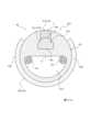
次に、図6~図8を参照して、保持部70を構成する別の貫通孔の一例としての貫通孔61c4について説明する。図6、保持部70としての貫通孔61c4を備える画像診断用カテーテル110の遠位端部を示す図である。図7は、図6に示す画像診断用カテーテル110のイメージングコア60の上面図である。図8は、図7のI-I線の位置での断面図である。 Next, with reference to FIGS. 6 to 8, the through hole 61c4 as an example of another through hole constituting the holdingportion 70 will be described. FIG. 6 is a diagram showing the distal end portion of thediagnostic imaging catheter 110 including the through hole 61c4 as the holdingportion 70. FIG. 7 is a top view of theimaging core 60 of thediagnostic imaging catheter 110 shown in FIG. 6. FIG. 8 is a sectional view taken along line II in FIG. 7.

図6~図8に示す画像診断用カテーテル110は、図1~図5に示す構成と比較して、イメージングコア60の構成が相違し、その他の構成は同一である。そのため、ここでは相違点についてのみ説明する。 Thediagnostic imaging catheter 110 shown in FIGS. 6 to 8 differs from the structure shown in FIGS. 1 to 5 in the structure of theimaging core 60, and the other structures are the same. Therefore, only the differences will be explained here.

図6~図8に示すイメージングコア60は、超音波送受信部61aと、光送受信部61bと、造影マーカ部材61cと、ハウジング61dと、先端部材61eと、光透過部材Xと、を備える。図6~図8に示すイメージングコア60では、ハウジング61dの近位筒部12bの遠位端の周方向の一部に切り欠き部12b1が形成されている。そして、X線造影性を有する造影マーカ部材61cは、この切り欠き部12b1の位置で、切り欠き部12b1と周方向で隣接する略C形状の周壁部12b2に固定されることで、ハウジング61dに支持されている。 Theimaging core 60 shown in FIGS. 6 to 8 includes an ultrasound transmitting/receivingsection 61a, a light transmitting/receivingsection 61b, acontrast marker member 61c, ahousing 61d, atip member 61e, and a light transmitting member X. In theimaging core 60 shown in FIGS. 6 to 8, a notch 12b1 is formed in a portion of the distal end of theproximal cylinder portion 12b of thehousing 61d in the circumferential direction. Thecontrast marker member 61c having X-ray contrast property is fixed to the substantially C-shaped peripheral wall portion 12b2 adjacent to the notch portion 12b1 in the circumferential direction at the position of the notch portion 12b1, thereby being attached to thehousing 61d. Supported.

また、図6~図8に示す造影マーカ部材61cは、光送受信部61bの光学素子61b1を覆うように配置されている。図6~図8に示すイメージングコア60の保持部70は、造影マーカ部材61cの、光送受信部61bの光学素子61b1を覆う位置に形成されている貫通孔61c4である。より具体的に、図6~図8に示す貫通孔61c4は、光学素子61b1としてのボールレンズの球面部65bを覆う位置に形成されている。 Further, thecontrast marker member 61c shown in FIGS. 6 to 8 is arranged to cover the optical element 61b1 of the optical transmitter/receiver 61b. The holdingportion 70 of theimaging core 60 shown in FIGS. 6 to 8 is a through hole 61c4 formed in thecontrast marker member 61c at a position covering the optical element 61b1 of the light transmitting/receivingportion 61b. More specifically, the through hole 61c4 shown in FIGS. 6 to 8 is formed at a position that covers thespherical portion 65b of the ball lens serving as the optical element 61b1.

このように、図6~図8に示すイメージングコア60では、光送受信部61bの光学素子61b1が、造影マーカ部材61cによって周囲が覆われている。そして、造影マーカ部材61cのうち、光学素子61b1に対してシャフト13の径方向外側の位置に、保持部70としての貫通孔61c4が形成されている。換言すれば、図6~図8に示す造影マーカ部材61cは、光学素子61b1を収容する収容部61c3を区画している。光送受信部61bは、光学素子61b1が造影マーカ部材61cの収容部61c3に収容された状態で支持されることで、ハウジング61dに位置決めされている。そして、貫通孔61c4は、収容部61c3に連なる一端から、シャフト13の径方向外側に向かって延在している。貫通孔61c4の他端は、ハウジング61dの切り欠き部12b1の位置で、造影マーカ部材61cの外面上に形成されている開口部である。 In this manner, in theimaging core 60 shown in FIGS. 6 to 8, the optical element 61b1 of the optical transmitter/receiver 61b is surrounded by thecontrast marker member 61c. A through hole 61c4 serving as a holdingportion 70 is formed in thecontrast marker member 61c at a position radially outward of theshaft 13 with respect to the optical element 61b1. In other words, thecontrast marker member 61c shown in FIGS. 6 to 8 defines a housing portion 61c3 that accommodates the optical element 61b1. The optical transmitter/receiver 61b is positioned in thehousing 61d by supporting the optical element 61b1 accommodated in the accommodating portion 61c3 of thecontrast marker member 61c. The through hole 61c4 extends radially outward of theshaft 13 from one end connected to the housing portion 61c3. The other end of the through hole 61c4 is an opening formed on the outer surface of thecontrast marker member 61c at the position of the notch 12b1 of thehousing 61d.

図6~図8に示すように、保持部70としての貫通孔61c4には、光透過部材Xが保持されている。 As shown in FIGS. 6 to 8, the light transmitting member X is held in the through hole 61c4 serving as the holdingportion 70. As shown in FIGS.

このように、保持部70は、造影マーカ部材61cに形成されている貫通孔61c4により構成されてもよい。この場合、長手方向Aにおいて、造影マーカ部材61cの位置と、光学素子61b1の位置と、を一致させることができる。そのため、アンギオ装置等により、造影マーカ部材61cの位置を確認することで、光学素子61b1の正確な位置を把握することができる。 In this way, the holdingpart 70 may be configured by the through hole 61c4 formed in thecontrast marker member 61c. In this case, in the longitudinal direction A, the position of thecontrast marker member 61c and the position of the optical element 61b1 can be matched. Therefore, by confirming the position of thecontrast marker member 61c using an angiography device or the like, the accurate position of the optical element 61b1 can be determined.

また、図6~図8に示す超音波送受信部61aについても、光送受信部61bの光学素子61b1より遠位側に位置している。そのため、図8に示すように、造影マーカ部材61cには、超音波送受信部61aに接続されている電気信号線14aが挿通される挿通孔61c2が形成されている。図8に示すように、光学素子61b1を収容する収容部61c3は、シャフト13の中心軸線O上に配置されておらず、シャフト13の中心軸線Oより、シャフト13の径方向外側に位置する。これによって、電気信号線14aが挿通される挿通孔61c2を確保し易くなる。この点は、図1~図5に示す画像診断用カテーテル110においても同様である。 Further, the ultrasonic transmitting/receivingsection 61a shown in FIGS. 6 to 8 is also located on the distal side from the optical element 61b1 of the optical transmitting/receivingsection 61b. Therefore, as shown in FIG. 8, thecontrast marker member 61c is formed with an insertion hole 61c2 through which theelectric signal line 14a connected to the ultrasound transmitting/receivingsection 61a is inserted. As shown in FIG. 8, the accommodating portion 61c3 that accommodates the optical element 61b1 is not arranged on the central axis O of theshaft 13, but is located on the outer side of theshaft 13 in the radial direction from the central axis O of theshaft 13. This makes it easier to secure the insertion hole 61c2 through which theelectric signal line 14a is inserted. This point also applies to thediagnostic imaging catheter 110 shown in FIGS. 1 to 5.

本開示に係る画像診断用カテーテルは、上述した実施形態及び変形例に示す具体的な構成に限られず、特許請求の範囲の記載を逸脱しない限り、種々の変形、変更、組み合わせが可能である。 The diagnostic imaging catheter according to the present disclosure is not limited to the specific configurations shown in the embodiments and modifications described above, and various modifications, changes, and combinations are possible without departing from the scope of the claims.

本開示は画像診断用カテーテルに関する。 The present disclosure relates to catheters for diagnostic imaging.

10:プローブ
12a:遠位筒部
12b:近位筒部
12b1:切り欠き部
12b2:周壁部
12c:支持板部
13:シャフト
14a:電気信号線
14b:導光部材
20:シース
20a:本体部
20b:ガイドワイヤ挿通部
21a:第1中空部
21b:第2中空部
22:補強部材
22a:連通路
22a1:連通孔
23:造影マーカ部
30:内管
31:内管本体
32:ハブ
40:外管
41:外管本体
42:遠位側コネクタ
43:近位側コネクタ
60:イメージングコア
61a:超音波送受信部
61b:光送受信部
61b1:光学素子
61c:造影マーカ部材
61c1、61c2:挿通孔
61c3:収容部
61c4:貫通孔(保持部の一例)
61d:ハウジング
61d1:窓部
61d2:貫通孔(保持部の一例)
61e:先端部材
62:超音波振動子
62a:本体部
62b:電極
65a:平面部
65b:球面部
70:保持部
80:バッキング部材
100:画像診断装置
110:画像診断用カテーテル
110a:挿入部
110b:操作部
120:外部装置
120a:駆動ユニット
120b:制御装置
120c:モニタ
121、122:モータ
123:ボールネジ
A:画像診断用カテーテルの長手方向
A1:挿入方向
A2:抜去方向
O:シャフトの中心軸線
W:ガイドワイヤ
X:光透過部材
10: Probe 12a:Distal cylinder part 12b: Proximal cylinder part 12b1: Notch part 12b2:Peripheral wall part 12c: Support plate part 13:Shaft 14a:Electric signal line 14b: Light guide member 20:Sheath 20a:Main body part 20b : Guidewire insertion part 21a: Firsthollow part 21b: Second hollow part 22:Reinforcement member 22a: Communication path 22a1: Communication hole 23: Contrast marker part 30: Inner tube 31: Inner tube main body 32: Hub 40: Outer tube 41: Outer tube body 42: Distal connector 43: Proximal connector 60:Imaging core 61a: Ultrasonic transmitter/receiver 61b: Light transmitter/receiver 61b1:Optical element 61c: Contrast marker members 61c1, 61c2: Through hole 61c3: Accommodation Part 61c4: Through hole (an example of a holding part)
61d: Housing 61d1: Window 61d2: Through hole (an example of a holding part)
61e: Tip member 62:Ultrasonic transducer 62a:Main body portion 62b:Electrode 65a:Planar portion 65b: Spherical portion 70: Holding portion 80: Backing member 100: Diagnostic imaging device 110:Diagnostic imaging catheter 110a:Insertion portion 110b: Operation unit 120:External device 120a:Drive unit 120b:Control device 120c:Monitors 121, 122: Motor 123: Ball screw A: Longitudinal direction A1 of the diagnostic imaging catheter: Insertion direction A2: Removal direction O: Center axis W of the shaft: Guide wire X: light transmitting member

Claims (8)

Translated fromJapanese
体腔の断層画像を取得するための画像診断用カテーテルであって、
長尺状のシースと、
前記シース内に配置されるシャフトと、
前記シャフトの遠位端部に固定されているイメージングコアと、を備え、
前記イメージングコアは、
光学素子を備える光送受信部と、
超音波送受信部と、
前記光送受信部の前記光学素子を覆う位置に硬化前の流動性を有する状態の光透過部材を保持可能な保持部と、を備える、画像診断用カテーテル。
An image diagnostic catheter for obtaining a tomographic image of a body cavity, the catheter comprising:
a long sheath;
a shaft disposed within the sheath;
an imaging core fixed to the distal end of the shaft;
The imaging core includes:
an optical transmitter/receiver section including an optical element;
An ultrasonic transmitter and receiver,
A catheter for diagnostic imaging, comprising: a holding part capable of holding a fluid light transmitting member before curing at a position covering the optical element of the light transmitting/receiving part.
前記イメージングコアは、前記光送受信部及び前記超音波送受信部を支持するハウジングを備え、
前記保持部は、前記ハウジングのうち前記光送受信部の前記光学素子を覆う位置に形成されている貫通孔である、請求項1に記載の画像診断用カテーテル。
The imaging core includes a housing that supports the optical transmitter/receiver and the ultrasound transmitter/receiver,
The catheter for image diagnosis according to claim 1, wherein the holding section is a through hole formed in the housing at a position covering the optical element of the optical transmitting and receiving section.
前記イメージングコアは、前記光送受信部の前記光学素子より近位側に、X線造影性を有する造影マーカ部材を備え、
前記造影マーカ部材には、前記光送受信部の前記光学素子に接続される導光部材が挿通される挿通孔が形成されている、請求項1又は2に記載の画像診断用カテーテル。
The imaging core includes a contrast marker member having X-ray contrast property on a proximal side of the optical element of the optical transmitting and receiving unit,
3. The diagnostic imaging catheter according to claim 1, wherein the contrast marker member has an insertion hole through which a light guide member connected to the optical element of the light transmitting/receiving section is inserted.
前記イメージングコアは、前記光送受信部の前記光学素子を覆うように配置され、X線造影性を有する造影マーカ部材を備え、
前記保持部は、前記造影マーカ部材の前記光送受信部の前記光学素子を覆う位置に形成されている貫通孔である、請求項1に記載の画像診断用カテーテル。
The imaging core is arranged to cover the optical element of the optical transmitting and receiving unit, and includes a contrast marker member having X-ray contrast properties,
The diagnostic imaging catheter according to claim 1, wherein the holding section is a through hole formed at a position covering the optical element of the optical transmitting and receiving section of the contrast marker member.
前記イメージングコアは、前記光送受信部及び前記超音波送受信部を支持するハウジングを備え、
前記造影マーカ部材は、前記ハウジングに支持されている、請求項4に記載の画像診断用カテーテル。
The imaging core includes a housing that supports the optical transmitter/receiver and the ultrasound transmitter/receiver,
The diagnostic imaging catheter according to claim 4, wherein the contrast marker member is supported by the housing.
前記超音波送受信部は、前記光送受信部の前記光学素子より遠位側に位置し、
前記造影マーカ部材には、前記超音波送受信部に接続されている電気信号線が挿通される挿通孔が形成されている、請求項3から5のいずれか1つに記載の画像診断用カテーテル。
The ultrasonic transmitter/receiver is located on a distal side than the optical element of the optical transmitter/receiver,
The diagnostic imaging catheter according to any one of claims 3 to 5, wherein the contrast marker member has an insertion hole through which an electric signal line connected to the ultrasound transmitting/receiving section is inserted.
前記光送受信部の前記光学素子は、ボールレンズである、請求項1から6のいずれか1つに記載の画像診断用カテーテル。 The catheter for diagnostic imaging according to any one of claims 1 to 6, wherein the optical element of the optical transmitter/receiver is a ball lens. 前記イメージングコアは、前記保持部に保持される前記光透過部材を備える、請求項1から7のいずれか1つに記載の画像診断用カテーテル。 The catheter for diagnostic imaging according to any one of claims 1 to 7, wherein the imaging core includes the light transmitting member held by the holding portion.
JP2022051867A2022-03-282022-03-28Catheter for diagnostic imagingPendingJP2023144742A (en)

Priority Applications (1)

Application NumberPriority DateFiling DateTitle
JP2022051867AJP2023144742A (en)2022-03-282022-03-28Catheter for diagnostic imaging

Applications Claiming Priority (1)

Application NumberPriority DateFiling DateTitle
JP2022051867AJP2023144742A (en)2022-03-282022-03-28Catheter for diagnostic imaging

Publications (1)

Publication NumberPublication Date
JP2023144742Atrue JP2023144742A (en)2023-10-11

Family

ID=88253071

Family Applications (1)

Application NumberTitlePriority DateFiling Date
JP2022051867APendingJP2023144742A (en)2022-03-282022-03-28Catheter for diagnostic imaging

Country Status (1)

CountryLink
JP (1)JP2023144742A (en)

Citations (4)

* Cited by examiner, † Cited by third party
Publication numberPriority datePublication dateAssigneeTitle
JP2010516305A (en)*2007-01-192010-05-20サニーブルック・ヘルス・サイエンシズ・センター Scanning mechanism for imaging probe
WO2017130927A1 (en)*2016-01-262017-08-03テルモ株式会社Image display device and method for controlling same
WO2020203423A1 (en)*2019-03-292020-10-08テルモ株式会社Image diagnosis catheter
CN213309872U (en)*2020-09-212021-06-01武汉阿格斯科技有限公司Optical and acoustic combined probe

Patent Citations (4)

* Cited by examiner, † Cited by third party
Publication numberPriority datePublication dateAssigneeTitle
JP2010516305A (en)*2007-01-192010-05-20サニーブルック・ヘルス・サイエンシズ・センター Scanning mechanism for imaging probe
WO2017130927A1 (en)*2016-01-262017-08-03テルモ株式会社Image display device and method for controlling same
WO2020203423A1 (en)*2019-03-292020-10-08テルモ株式会社Image diagnosis catheter
CN213309872U (en)*2020-09-212021-06-01武汉阿格斯科技有限公司Optical and acoustic combined probe

Similar Documents

PublicationPublication DateTitle
JP6584467B2 (en) Photo-acoustic imaging device
US9259184B2 (en)Probe for insertion into a living body
JP6378787B2 (en) Design and method for an intravascular catheter
US11596310B2 (en)Image diagnosis catheter
JP7179943B2 (en) diagnostic imaging catheter
JP5171355B2 (en) In vivo probe device
JP5171354B2 (en) In vivo diagnostic imaging probe
JP7618513B2 (en) Diagnostic Imaging Catheters
US11406356B2 (en)Image diagnosis catheter
JP6805009B2 (en) Diagnostic imaging catheter
JP2023144742A (en)Catheter for diagnostic imaging
EP3932325B1 (en)Image diagnosis catheter
WO2024176636A1 (en)Method for manufacturing catheter for diagnostic imaging, and catheter for diagnostic imaging
WO2025142241A1 (en)Catheter for diagnostic imaging
JP2025145702A (en) Diagnostic imaging catheters
JP6949579B2 (en) Diagnostic imaging catheter

Legal Events

DateCodeTitleDescription
A621Written request for application examination

Free format text:JAPANESE INTERMEDIATE CODE: A621

Effective date:20241113

A977Report on retrieval

Free format text:JAPANESE INTERMEDIATE CODE: A971007

Effective date:20250625

A131Notification of reasons for refusal

Free format text:JAPANESE INTERMEDIATE CODE: A131

Effective date:20250805


[8]ページ先頭

©2009-2025 Movatter.jp