JP2023141271A - Portable radiation measuring unit - Google Patents
Portable radiation measuring unitDownload PDFInfo
- Publication number
- JP2023141271A JP2023141271AJP2022047501AJP2022047501AJP2023141271AJP 2023141271 AJP2023141271 AJP 2023141271AJP 2022047501 AJP2022047501 AJP 2022047501AJP 2022047501 AJP2022047501 AJP 2022047501AJP 2023141271 AJP2023141271 AJP 2023141271A
- Authority
- JP
- Japan
- Prior art keywords
- probe
- radiation measuring
- portable radiation
- measuring device
- end surface
- Prior art date
- Legal status (The legal status is an assumption and is not a legal conclusion. Google has not performed a legal analysis and makes no representation as to the accuracy of the status listed.)
- Granted
Links
Images


Landscapes
- Measurement Of Radiation (AREA)
- Nuclear Medicine (AREA)
Abstract
Description
Translated fromJapanese特許法第30条第2項適用申請有り ・ウェブサイトのアドレス https://www.nsr.go.jp/disclosure/committee/other_meetings/20210325_01.html https://www.nsr.go.jp/data/000346903.pdf 掲載日 令和3年3月25日 ・研究集会名 第2回緊急時の甲状腺被ばく線量モニタリングに関する検討チーム 開催場所 オンライン開催 開催日 令和3年3月25日 ・展示会名 令和3年度第1回甲状腺簡易測定研修 開催場所 国立研究開発法人量子科学技術研究開発機構千葉地区研修棟 展示日 令和3年8月11日 ・展示会名 令和3年度第2回甲状腺簡易測定研修 開催場所 国立研究開発法人量子科学技術研究開発機構千葉地区研修棟 展示日 令和3年10月13日から令和4年1月7日 ・展示会名 令和3年度第3回甲状腺簡易測定研修 開催場所 国立研究開発法人量子科学技術研究開発機構千葉地区研修棟 展示日 令和4年1月7日Application for application of Article 30,
本発明は、被検者の甲状腺から放出される放射線を測定する可搬型放射線測定器に関する。 The present invention relates to a portable radiation measuring device that measures radiation emitted from the thyroid of a subject.
原子力・放射線事故によって環境中に放出された放射性物質を摂取すると、人体に内部被ばくがもたされる。放射性物質である放射性ヨウ素の摂取による人体の内部被ばくを評価するために、放射性ヨウ素が蓄積され易い甲状腺から放出される放射線を測定することが有効である。そのため、被検者の甲状腺から放出される放射線を測定する可搬型放射線測定器が開発されている(非特許文献1及び非特許文献2参照)。先行技術に係る放射線測定器の構成について簡単に説明すると、次のようになる。 Ingestion of radioactive materials released into the environment due to nuclear and radiation accidents results in internal exposure to the human body. In order to evaluate the internal exposure of the human body due to ingestion of radioactive iodine, which is a radioactive substance, it is effective to measure the radiation emitted from the thyroid gland, where radioactive iodine tends to accumulate. Therefore, a portable radiation measuring device that measures radiation emitted from the thyroid of a subject has been developed (see Non-Patent Document 1 and Non-Patent Document 2). A brief description of the configuration of the radiation measuring device according to the prior art is as follows.
先行技術に係る放射線測定器は、金属からなる角パイプ状の測定器本体を備えており、測定器本体は、その上面側に、持ち手部を有している。測定器本体の先端部には、金属からなるアーム部材が設けられており、アーム部材は、測定器本体に対して回動調節可能に構成されている。アーム部材の先端部には、中空状のプローブが設けられており、プローブの後端側の部分は、金属からなる。プローブの先端面は、被検者の頸部の前面に接触可能であって、凹状に湾曲するように形成されている。 The radiation measuring device according to the prior art includes a square pipe-shaped measuring device main body made of metal, and the measuring device main body has a handle portion on its upper surface side. An arm member made of metal is provided at the tip of the measuring instrument main body, and the arm member is configured to be rotatably adjustable with respect to the measuring instrument main body. A hollow probe is provided at the tip of the arm member, and the rear end portion of the probe is made of metal. The distal end surface of the probe is capable of contacting the front surface of the neck of the subject and is curved in a concave manner.
プローブ内における先端面側には、被検者の甲状腺から放出される放射線を検出する複数の検出素子が設けられている。測定器本体内には、複数の検出素子から出力された電気信号を処理する回路基板が設けられている。複数の検出素子と回路基板を接続する複数の配線ケーブルは、アーム部材とプローブとの間において外部に露出した状態で配置されている。 A plurality of detection elements are provided on the distal end side of the probe to detect radiation emitted from the thyroid of the subject. A circuit board for processing electrical signals output from a plurality of detection elements is provided inside the measuring instrument body. A plurality of wiring cables connecting the plurality of detection elements and the circuit board are arranged between the arm member and the probe in a state where they are exposed to the outside.
ところで、プローブが測定器本体の先端側にアーム部材を介して設けられているため、可搬型放射線測定器はプローブの長さ方向(幅方向及び厚み方向に直交する方向)に延伸する傾向にある。そのため、可搬型放射線測定器の大型化及び重量増大を招いて、可搬型放射線測定器の取扱性が低下するという問題がある。 By the way, since the probe is provided on the distal end side of the measuring instrument body via an arm member, portable radiation measuring instruments tend to extend in the length direction of the probe (direction perpendicular to the width direction and thickness direction). . Therefore, there is a problem in that the portable radiation measuring device becomes larger and heavier, and the handling of the portable radiation measuring device deteriorates.
特に、複数の配線ケーブルがアーム部材とプローブとの間において外部に露出しているため、被検者の甲状腺からの放射線を測定する際に、配線ケーブルが被検者周辺の物体と干渉しないようする必要があり、可搬型放射線測定器の取扱性が更に低下するという問題がある。 In particular, since multiple wiring cables are exposed to the outside between the arm member and the probe, when measuring radiation from the patient's thyroid, prevent the wiring cables from interfering with objects around the patient. There is a problem that the handling of the portable radiation measuring device is further deteriorated.
そこで、本発明の一態様は、可搬型放射線測定器の小型化及び軽量化を図って、可搬型放射線測定器の取扱性を高めることを目的とする。 Therefore, an object of one aspect of the present invention is to reduce the size and weight of a portable radiation measuring device and to improve the ease of handling the portable radiation measuring device.
前述の課題を解決するため、本発明の一態様に係る可搬型放射線測定器は、先端面が被検者の頸部の前面に接触可能であってかつ凹状に湾曲するように形成された中空状のプローブと、前記プローブの後端面に直結され、内部が前記プローブの内部に連通した中空棒状の持ち手部と、前記プローブ内における前記先端面側に設けられ、被検者の甲状腺から放出された放射線を検出する検出素子と、前記検出素子から出力された電気信号を処理する回路基板と、を備え、前記持ち手部は、前記検出素子と前記回路基板を接続する配線ケーブルを収容するように構成されている。 In order to solve the above-mentioned problems, a portable radiation measuring device according to one aspect of the present invention includes a hollow body whose distal end surface is capable of contacting the front surface of the subject's neck and is curved in a concave shape. a hollow rod-shaped handle directly connected to the rear end surface of the probe and whose interior communicates with the inside of the probe; a detection element that detects the radiation that is detected, and a circuit board that processes the electrical signal output from the detection element, and the handle part accommodates a wiring cable that connects the detection element and the circuit board. It is configured as follows.
本発明の一態様によれば、可搬型放射線測定器の小型化及び軽量化を図って、可搬型放射線測定器の取扱性を高めることができる。 According to one aspect of the present invention, it is possible to reduce the size and weight of a portable radiation measuring device and improve the ease of handling the portable radiation measuring device.
以下、本発明の実施形態について図面を参照して説明する。本願の明細書及び特許請求の範囲において、「幅方向」とは、可搬型放射線測定器、測定器本体、又はプローブの幅方向のことである。「厚み方向」とは、可搬型放射線測定器、測定器本体、又はプローブの厚み方向のことである。「長さ方向」とは、可搬型放射線測定器、測定器本体、又はプローブの長さ方向のことであり、幅方向及び厚み方向に直交する方向のことである。図面中、「WD」は幅方向、「TD」は厚み方向、「LD」は長さ方向、「LDa」は先端側又は先端方向、「LDb」は後端側又は後端方向をそれぞれ指している。 Embodiments of the present invention will be described below with reference to the drawings. In the specification and claims of the present application, the "width direction" refers to the width direction of the portable radiation measuring instrument, the measuring instrument body, or the probe. "Thickness direction" refers to the thickness direction of a portable radiation measuring instrument, a measuring instrument body, or a probe. The "length direction" refers to the length direction of a portable radiation measuring instrument, a measuring instrument body, or a probe, and is a direction perpendicular to the width direction and the thickness direction. In the drawings, "WD" refers to the width direction, "TD" refers to the thickness direction, "LD" refers to the length direction, "LDa" refers to the tip side or the tip direction, and "LDb" refers to the rear end side or the rear end direction. There is.
図1から図11を参照して、本実施形態に係る可搬型放射線測定器10の構成について説明する。図1は、本実施形態に係る可搬型放射線測定器10の斜視図である。図2は、本実施形態に係る可搬型放射線測定器10の平面図である。図3は、本実施形態に係る可搬型放射線測定器10の底面図である。図4は、本実施形態に係る可搬型放射線測定器10の右側面図である。図5は、本実施形態に係る可搬型放射線測定器10の左側面図である。図6は、本実施形態に係る可搬型放射線測定器10の正面図である。図7は、本実施形態に係る可搬型放射線測定器10の背面図である。図8は、本実施形態に係る可搬型放射線測定器10の内部の様子を示す模式図であり、蓋部材12aを取外した状態を示している。図9は、図2におけるIX-IX線に沿った断面図である。図10のXAは、乳児の標準人体数学ファントムの頸部の高さ寸法及び曲率半径を示す模式的な図である。図10のXBは、1歳児の標準人体数学ファントムの頸部の高さ寸法及び曲率半径を示す模式的な図である。図11のXIAは、5歳児の標準人体数学ファントムの頸部の高さ寸法及び曲率半径を示す模式的な図である。図11のXIBは、10歳児の標準人体数学ファントムの頸部の高さ寸法及び曲率半径を示す模式的な図である。 The configuration of the portable
(可搬型放射線測定器10の概要、測定器本体12)
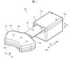
図1に示すように、本実施形態に係る可搬型放射線測定器10は、被検者の甲状腺から放出される放射線を測定する測定器である。可搬型放射線測定器10の測定対象は、放射線のうちの例えばγ線である。可搬型放射線測定器10は、中空状の測定器本体12を備えており、測定器本体12は、取外し可能な蓋部材12aを有している。測定器本体12の長さ方向の寸法は、測定器本体12の幅方向の最大寸法よりも大きく設定されており、測定器本体12の長さ方向が測定器本体12の長手方向になっている。なお、測定器本体12の長さ方向の寸法が測定器本体12の幅方向の最大寸法よりも短く設定されてもよい。(Outline of portable radiation measuring
As shown in FIG. 1, a portable
(プローブ14、先端面14a)
図1から図6に示すように、測定器本体12は、中空状のプローブ14を備えており、プローブ14は、例えばポリエチレンテレフタレート又はポリエチレン等の合成樹脂からなる。プローブ14の先端面14aは、被検者の頸部SCの前面に接触可能である。プローブ14の先端面14aは、後端面14b側に向かって凹状に湾曲するように形成されている。具体的には、プローブ14の先端面14aは、1つの曲率半径を有した湾曲形状の一例である円弧形状に形成されている。なお、プローブ14の先端面14aを円弧形状に形成する代わりに、複数の曲率半径を有した湾曲形状に形成してもよい。(
As shown in FIGS. 1 to 6, the measuring device
(後端面14b、湾曲部14e)
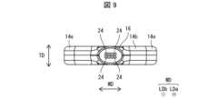
図1から図5、図7に示すように、プローブ14の後端面14bは、先端面14aに沿って凹状に湾曲するように形成されている。具体的には、プローブ14の後端面14bは、1つの曲率半径を有した湾曲形状の一例である円弧形状に形成されており、プローブ14の後端面14bの曲率中心は、プローブ14の先端面14aの曲率中心に一致している。プローブ14の後端面14bの曲率半径は、プローブ14の先端面14aの曲率半径よりも大きくなっている。プローブ14の後端面14bにおける幅方向の両側には、それぞれ、プローブ14の先端面14aの曲率半径よりも小さい曲率半径を有した湾曲部14eが形成されている。なお、プローブ14の後端面14bを円弧形状に形成する代わりに、複数の曲率半径を有した湾曲形状に形成してもよい。プローブ14の後端面14bの曲率中心は、プローブ14の先端面14aの曲率中心に対してずれてもよい。(
As shown in FIGS. 1 to 5 and 7, the
(持ち手部16)
図1から図5、図8、図9に示すように、測定器本体12は、プローブ14の後端面14bにおける幅方向の中央部に直結された中空棒状の持ち手部16を備えている。持ち手部16の内部は、プローブ14の内部に連通している。持ち手部16は、プローブ14と同様に、例えばポリエチレンテレフタレート又はポリエチレン等の合成樹脂からなる。持ち手部16の厚み方向に沿った断面外形は、楕円形状である。なお、持ち手部16の厚み方向に沿った断面形状を楕円形状に形成する代わりに、長円形状又は円形状に形成してもよい。(Handle part 16)
As shown in FIGS. 1 to 5, 8, and 9, the measuring device
(収容部18)
図1から図8に示すように、測定器本体12は、持ち手部16の基端部に直結された中空状の収容部18を備えており、収容部18の内部は、持ち手部16の内部に連通している。収容部18は、プローブ14及び持ち手部16と同様に、例えばポリエチレンテレフタレート又はポリエチレン等の合成樹脂からなる。(Accommodation part 18)
As shown in FIGS. 1 to 8, the measuring instrument
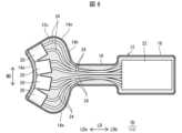
(シールド膜12c)
図8に示すように、測定器本体12の内面(プローブ14の内面、持ち手部16の内面、及び収容部18の内面)には、外部から電磁波を遮蔽するシールド膜12cが形成されている。シールド膜12cは、例えば導電性塗料からなる。(
As shown in FIG. 8, a
(検出素子20)
図8に示すように、プローブ14内における先端面14a側には、被検者の甲状腺から放出された放射線を検出する複数の検出素子20が設けられている。各検出素子20は、放射線の光量に応じた電気信号を出力する。各検出素子20は、GAGG(ガドリニウム・アルミニウム・ガリウム・ガーネット)シンチレータ、CsI(ヨウ化セシウム)シンチレータ、NaI(ヨウ化ナトリウム)シンチレータ、BGO(Bismuth Germanium Oxide)シンチレータ、GSO(Gadolinium Silicon Oxide)シンチレータ、SrI(ヨウ化ストロンチウム)シンチレータ、LaBr3(臭化ランタン)シンチレータ、CeBr3(臭化セリウム)シンチレータ、LYSO(Lutetium Yttrium Oxyorthosilicate)シンチレータ、LSO(Lutetium Oxyorthosilicate)シンチレータ等のシンチレータを有している。各検出素子20は、その検出面を除いて、シールド膜12cによって外部からの電磁波に対して遮蔽されている。(Detection element 20)
As shown in FIG. 8, a plurality of
(回路基板22、配線ケーブル24)
図8及び図9に示すように、収容部18内には、複数の検出素子20から出力された電気信号を処理するリジットタイプの回路基板22が設けられている。換言すれば、中空状の収容部18は、リジットタイプの回路基板22を収容する。また、可搬型放射線測定器10は、複数の検出素子20と回路基板22とを接続する複数の配線ケーブル24を備えている。複数の配線ケーブル24は、プローブ14内から持ち手部16内に亘って配置されている。換言すれば、持ち手部16は、複数の配線ケーブル24を収容するように構成されている。(
As shown in FIGS. 8 and 9, a rigid
可搬型放射線測定器10は、パーソナルコンピュータ又はタブレット端末等からなる解析装置(不図示)にUSBケーブル等の外部ケーブル(不図示)を介して接続可能である。解析装置は、回路基板22から出力される波高データを取り込んで、専用のソフトウェアで解析し、その解析結果を表示する。回路基板22への電力供給は、外部ケーブルを介して解析装置によって行われる。又は、回路基板22への電力供給は、外付けバッテリー(不図示)によって行われる。 The portable
なお、回路基板22はリジットタイプに限るものでなく、フレキシブルタイプであってもよい。回路基板22がフレキシブルタイプである場合には、回路基板22を持ち手部16又はプローブ14に収容してもよい。 Note that the
(プローブ14の厚み寸法)
図1、図4、及び図5に示すように、プローブ14の厚み寸法は、標準的な乳児の頸部の高さ寸法よりも小さく設定されている。これは、プローブ14の厚み寸法が標準的な乳児の頸部の高さ寸法以上になると、プローブ14の先端面14aを乳児の頸部の前面に接触させ難くなるからである。また、プローブ14の厚み寸法は、標準的な乳児の頸部の高さ寸法の0.8倍以上に設定されている。これは、プローブの厚み寸法が標準的な乳児の頸部の高さ寸法の0.8倍未満であると、各検出素子20の検出面が小さくなって、可搬型放射線測定器10の測定精度が低下することが懸念されるからである。(Thickness dimension of probe 14)
As shown in FIGS. 1, 4, and 5, the thickness of the
本実施形態においては、図10のXAに示すように、標準的な乳児の頸部の高さ寸法は、標準的な乳児の人体形状をコンピュータ上に再現した乳児の標準人体数学ファントムの頸部の高さ寸法である。図10のXAに示すように、乳児(0歳児)の標準人体数学ファントムの頸部の高さは、23.3mmであり、乳児の標準人体数学ファントムの頸部の曲率半径は、28.0mmである。図10のXBに参考として示すように、1歳児の標準人体数学ファントムの頸部の高さは、34.8mmであり、1歳児の標準人体数学ファントムの頸部の曲率半径は、36.0mmである。図11のXIAに参考として示すように、5歳児の標準人体数学ファントムの頸部の高さは、48.7mmであり、5歳児の標準人体数学ファントムの頸部の曲率半径は、38.0mmである。図11のXIBに参考として示すように、10歳児の標準人体数学ファントムの頸部の高さは、66.6mmであり、10歳児の標準人体数学ファントムの頸部の曲率半径は、44.0mmである。 In the present embodiment, as shown in XA in FIG. is the height dimension. As shown in XA of Fig. 10, the height of the neck of the standard human mathematics phantom for infants (0 year old) is 23.3 mm, and the radius of curvature of the neck of the standard human mathematics phantom for infants is 28.0 mm. It is. As shown in XB of Figure 10 for reference, the height of the neck of the standard human mathematics phantom for one-year-old children is 34.8 mm, and the radius of curvature of the neck of the standard human mathematics phantom for one-year-old children is 36.0 mm. It is. As shown in XIA in Figure 11 for reference, the height of the neck of the standard human mathematics phantom for 5-year-old children is 48.7 mm, and the radius of curvature of the neck of the standard human mathematics phantom for 5-year-old children is 38.0 mm. It is. As shown in XIB of Figure 11 for reference, the height of the neck of the standard human mathematics phantom for 10-year-old children is 66.6 mm, and the radius of curvature of the neck of the standard human mathematics phantom for 10-year-old children is 44.0 mm. It is.
なお、標準的な乳児の頸部の高さ寸法は、乳児の標準人体数学ファントムの頸部の高さ寸法に限るものでなく、公共又は民間の調査機関が調査した高さ寸法を用いてもよい。 Note that the standard infant neck height dimension is not limited to the neck height dimension of the standard human body mathematics phantom for infants, and height dimensions investigated by public or private research institutions may also be used. good.
プローブ14の厚み寸法は、プローブ14の先端面14aの曲率半径の0.5倍以下に設定されている。これは、プローブ14の厚み寸法がプローブ14の先端面14aの曲率半径の0.5倍を超えると、プローブ14の厚み寸法が大きくなって、プローブ14の先端面14aを乳児の頸部の前面に接触させ難くなるからである。また、プローブ14の厚み寸法は、プローブ14の先端面14aの曲率半径の0.4倍以上に設定されている。これは、プローブ14の先端面14aの曲率半径の0.4倍未満であると、各検出素子20の検出面が小さくなって、可搬型放射線測定器10の測定精度が低下することが懸念されるからである。なお、プローブ14の先端面14aが複数の曲率半径を有している場合には、プローブ14の先端面14aの曲率半径とは、複数の曲率半径の平均値のことである。 The thickness of the
(持ち手部16の厚み寸法、収容部18の幅寸法)
図4及び図5に示すように、持ち手部16の厚み寸法は、プローブ14の厚み寸法と同じに設定されている。また、図2及び図3に示すように、収容部18の幅寸法は、持ち手部16の幅寸法よりも大きくかつプローブ14の幅寸法よりも小さく設定されている。(Thickness dimension of
As shown in FIGS. 4 and 5, the thickness of the
(可搬型放射線測定器10の重量バランスに関する構成)
図1から図3に示すように、持ち手部16の一部を支点としたとき、収容部18は、プローブ14に働く重量に対応する重量を有している。換言すれば、持ち手部16の一部を支点としたとき、収容部18に働く重量は、プローブ14に働く重量と対応している。また、平面視したときに、可搬型放射線測定器10の重心位置は、持ち手部16上に位置している。なお、平面視したときに、可搬型放射線測定器10の重心位置が持ち手部16から外れた位置に位置してもよい。(Configuration related to weight balance of portable radiation measuring device 10)
As shown in FIGS. 1 to 3, when a portion of the
(作用効果)
続いて、本実施形態の作用効果について説明する。(effect)
Next, the effects of this embodiment will be explained.
可搬型放射線測定器10の構成においては、前述のように、持ち手部16がプローブ14の後端面の幅方向の中央部に直結されている。そのため、可搬型放射線測定器10が長さ方向に延伸することを抑えることができる。これにより、本実施形態によれば、可搬型放射線測定器10の小型化及び軽量化を図って、可搬型放射線測定器10の取扱性を高めることができる。特に、プローブ14、持ち手部16、及び収容部18がそれぞれ合成樹脂からなるため、プローブ14等が金属からなる場合に比べて、可搬型放射線測定器10の軽量化を促進することができる。 In the configuration of the portable
可搬型放射線測定器10の構成においては、前述のように、持ち手部16が複数の配線ケーブル24を収容するように構成されている。そのため、複数の配線ケーブル24が外部に露出しなくなると共に、被検者の甲状腺からの放射線を測定する際に、複数の配線ケーブル24が被検者周辺の物体と干渉することがない。これにより、本実施形態によれば、可搬型放射線測定器10の取扱性をより高めることができる。 In the configuration of the portable
可搬型放射線測定器10の構成においては、前述のように、プローブ14の厚み寸法が標準的な乳児の頸部の高さ寸法よりも小さく設定されている。また、プローブ14の厚み寸法がプローブ14の先端面14aの曲率半径の0.5倍以下に設定されている。そのため、乳児を含む5歳以下の乳幼児の頸部SCの前面にプローブ14の先端面14aを容易に接触させることができる。これにより、本実施形態によれば、5歳以下の乳幼児の甲状腺から放出される放射線を容易に測定することができる。特に、前述のように、複数の配線ケーブル24が外部に露出することなく、可搬型放射線測定器10の小型化を図ることができるため、乳幼児の甲状腺から放出される放射線を測定する際に、乳幼児に与える圧迫感を十分に低減することができる。 In the configuration of the portable
可搬型放射線測定器10の構成においては、前述のように、プローブ14の厚み寸法が標準的な乳児の頸部の高さ寸法の0、8倍以上に設定されている。プローブ14の厚み寸法がプローブ14の先端面14aの曲率半径の0.4倍以上に設定されている。そのため、本実施形態によれば、可搬型放射線測定器10の測定精度を十分に確保することができる。 In the configuration of the portable
可搬型放射線測定器10の構成において、前述のように、持ち手部16の厚み寸法がプローブ14の厚み寸法と同じに設定されている。そのため、プローブ14の先端面14aを被検者の頸部SCの前面に接触させる際に、持ち手部16が被検者の頸部SC周辺に当たることがない。これにより、本実施形態によれば、被検者に不快感を与えないで、被検者の甲状腺からの放射線を測定することができる。 In the configuration of the portable
可搬型放射線測定器10の構成においては、プローブ14の後端面14bが先端面14aに沿って凹状に湾曲するように形成されているため、測定者が持ち手部を例えば第1指間腔で保持した状態で指先をプローブ14の後端面14b側に掛け易くなる。また、プローブ14の後端面14bにおける幅方向の両側にそれぞれ湾曲部14eが形成されているため、測定者がプローブ14の湾曲部14e側に掛け易くなる。更に、収容部18の幅寸法が持ち手部16の幅寸法よりも大きくかつプローブ14の幅寸法よりも小さく設定されているため、プローブ14に働く重力と収容部18に働く重力によって、可搬型放射線測定器10の重量バランスをある程度とることができる。これにより、本実施形態によれば、測定者が可搬型放射線測定器10を片方の手で持ち易くなり、可搬型放射線測定器10の取扱性をより高めることができる。特に、持ち手部16の厚み方向に沿った断面外形が楕円形状、長円形状、又は円形状であるため、測定者が持ち手部16を片方の手でより持ち易くなり、可搬型放射線測定器10の取扱性をより高めることができる。 In the configuration of the portable
可搬型放射線測定器10の構成において、前述のように、持ち手部16の一部を支点としたとき、収容部18がプローブ14に働く重量に対応する重量を有している。平面視したときに、可搬型放射線測定器10の重心位置が持ち手部16上に位置している。そのため、片方の手で可搬型放射線測定器10を持ち易くなり、可搬型放射線測定器10のハンドリング性能を向上させることができる。これにより、本実施形態によれば、測定者が被検者である5歳未満の乳幼児を片方の腕と片方の手で抱きかかえた状態で、もう片方の手で可搬型放射線測定器10を把持して、乳幼児の甲状腺からの放射線を安定して測定することができる。 In the configuration of the portable
〔まとめ〕
本発明の態様1に係る可搬型放射線測定器は、先端面が被検者の頸部の前面に接触可能であってかつ凹状に湾曲するように形成された中空状のプローブと、前記プローブの後端面に直結され、内部が前記プローブの内部に連通した中空棒状の持ち手部と、前記プローブ内における前記先端面側に設けられ、被検者の甲状腺から放出された放射線を検出する検出素子と、前記検出素子から出力された電気信号を処理する回路基板と、を備え、前記持ち手部は、前記検出素子と前記回路基板を接続する配線ケーブルを収容するように構成されている。〔summary〕
A portable radiation measuring device according to aspect 1 of the present invention includes a hollow probe whose distal end surface is capable of contacting the front surface of the neck of the subject and is curved in a concave shape; a hollow rod-shaped handle directly connected to the rear end surface and communicating with the inside of the probe; and a detection element provided on the distal end surface side of the probe to detect radiation emitted from the thyroid of the subject. and a circuit board that processes the electrical signal output from the detection element, and the handle portion is configured to accommodate a wiring cable that connects the detection element and the circuit board.
前記の構成によれば、前記持ち手部が前記プローブの後端面に直結されているため、前記可搬型放射線測定器が前記プローブの長さ方向に延伸することを抑えることができる。これにより、前記可搬型放射線測定器の小型化及び軽量化を図って、前記可搬型放射線測定器の取扱性を高めることができる。 According to the above configuration, since the handle portion is directly connected to the rear end surface of the probe, it is possible to prevent the portable radiation measuring device from extending in the length direction of the probe. Thereby, the portable radiation measuring device can be made smaller and lighter, and the handling of the portable radiation measuring device can be improved.
前記持ち手部が前記配線ケーブルを収容するように構成されているため、被検者の甲状腺からの放射線を測定する際に、前記配線ケーブルが被検者周辺の物体と干渉することがない。これにより、前記可搬型放射線測定器の取扱性をより高めることができる。 Since the handle portion is configured to accommodate the distribution cable, the distribution cable does not interfere with objects around the subject when measuring radiation from the thyroid of the subject. Thereby, the ease of handling of the portable radiation measuring device can be further improved.
本発明の態様2に係る可搬型放射線測定器は、前記態様1において、前記プローブの厚み寸法は、標準的な乳児の頸部の高さ寸法よりも小さく設定されてもよい。 In the portable radiation measuring device according to a second aspect of the present invention, in the first aspect, the thickness dimension of the probe may be set smaller than the height dimension of a standard infant's neck.
前記構成によれば、乳児を含む5歳以下の乳幼児の頸部の前面に前記プローブの前記先端面を容易に接触させることができ、5歳以下の乳幼児の甲状腺から放出される放射線を容易に測定することができる。 According to the configuration, the tip surface of the probe can be easily brought into contact with the front surface of the neck of infants under 5 years old, including infants, and radiation emitted from the thyroid gland of infants under 5 years old can be easily removed. can be measured.
本発明の態様3に係る可搬型放射線測定器は、前記態様2において、前記プローブの厚み寸法は、前記標準的な乳児の頸部の高さ寸法の0、8倍以上に設定されてもよい。 In the portable radiation measuring device according to aspect 3 of the present invention, in
前記の構成によれば、前記可搬型放射線測定器の測定精度を十分に確保することができる。 According to the above configuration, the measurement accuracy of the portable radiation measuring device can be sufficiently ensured.
本発明の態様4に係る可搬型放射線測定器は、前記態様2又は3において、前記標準的な乳児の頸部の高さ寸法は、標準的な乳児の人体形状をコンピュータ上に再現した標準人体数学ファントムの頸部の高さ寸法であってもよい。 In the portable radiation measuring device according to aspect 4 of the present invention, in the
本発明の態様5に係る可搬型放射線測定器は、前記態様1において、前記プローブの厚み寸法は、前記プローブの前記先端面の曲率半径の0.5倍以下に設定されてもよい。 In the portable radiation measuring device according to aspect 5 of the present invention, in aspect 1, the thickness of the probe may be set to be 0.5 times or less the radius of curvature of the tip surface of the probe.
前記構成によれば、乳児を含む5歳以下の乳幼児の頸部の前面に前記プローブの前記先端面を容易に接触させることができ、5歳以下の乳幼児の甲状腺から放出される放射線を容易に測定することができる。 According to the configuration, the tip surface of the probe can be easily brought into contact with the front surface of the neck of infants under 5 years old, including infants, and radiation emitted from the thyroid gland of infants under 5 years old can be easily removed. can be measured.
本発明の態様6に係る可搬型放射線測定器は、前記態様5において、前記プローブの厚み寸法は、前記プローブの前記先端面の曲率半径の0.4倍以上に設定されてもよい。 In the portable radiation measuring device according to aspect 6 of the present invention, in aspect 5, the thickness of the probe may be set to be 0.4 times or more the radius of curvature of the tip surface of the probe.
前記の構成によれば、前記可搬型放射線測定器の測定精度を十分に確保することができる。 According to the above configuration, the measurement accuracy of the portable radiation measuring device can be sufficiently ensured.
本発明の態様7に係る可搬型放射線測定器は、前記態様1から6のいずれかにおいて、前記プローブの前記後端面は、前記先端面に沿って凹状に湾曲するように形成されてもよい。 In the portable radiation measuring device according to aspect 7 of the present invention, in any one of aspects 1 to 6, the rear end surface of the probe may be formed to curve concavely along the tip surface.
前記の構成によれば、測定者が前記持ち手部を例えば指で挟んだ状態で指先を前記プローブの前記後端面側に掛け易くなる。これにより、測定者が前記可搬型放射線測定器を片方の手で持ち易くなり、前記可搬型放射線測定器の取扱性をより高めることができる。 According to the above-mentioned configuration, it becomes easy for the measurer to hang the fingertips on the rear end surface side of the probe while holding the handle portion between the fingers. This makes it easier for the measuring person to hold the portable radiation measuring device with one hand, and the ease of handling the portable radiation measuring device can be further improved.
本発明の態様8に係る可搬型放射線測定器は、前記態様7において、前記プローブの前記後端面における幅方向の両側に、それぞれ、前記先端面の曲率半径よりも小さい曲率半径の湾曲部が形成されてもよい。 In the portable radiation measuring device according to aspect 8 of the present invention, in the aspect 7, curved portions each having a radius of curvature smaller than the radius of curvature of the tip surface are formed on both sides of the rear end surface of the probe in the width direction. may be done.
前記の構成によれば、測定者が前記プローブの前記湾曲部側に掛け易くなる。これにより、測定者が前記可搬型放射線測定器を片方の手で持ち易くなり、前記可搬型放射線測定器の取扱性をより高めることができる。 According to the above configuration, the measurer can easily hang the probe on the curved portion side. This makes it easier for the measuring person to hold the portable radiation measuring device with one hand, and the ease of handling the portable radiation measuring device can be further improved.
本発明の態様9に係る可搬型放射線測定器は、前記態様1から8のいずれかにおいて、前記持ち手部の厚み方向に沿った断面外形は、楕円形状、長円形状、又は円形状であってもよい。 In the portable radiation measuring device according to aspect 9 of the present invention, in any one of aspects 1 to 8, the cross-sectional outline of the handle portion along the thickness direction is elliptical, oval, or circular. You can.
前記の構成によれば、測定者が前記持ち手部を片方の手で持ち易くなり、前記可搬型放射線測定器の取扱性をより高めることができる。 According to the above configuration, it becomes easier for the measuring person to hold the handle portion with one hand, and the ease of handling of the portable radiation measuring device can be further improved.
本発明の態様10に係る可搬型放射線測定器は、前記態様1から9のいずれかにおいて、前記持ち手部の厚み寸法は、前記プローブの厚み寸法と同じに設定されてもよい。 In the portable radiation measuring device according to
前記の構成によれば、前記プローブの前記先端面を被検者の頸部の前面に接触させる際に、前記持ち手部が被検者の頸部周辺に当たることがない。これにより、被検者に不快感を与えないで、被検者の甲状腺からの放射線を測定することができる。 According to the above configuration, when the distal end surface of the probe is brought into contact with the front surface of the neck of the subject, the handle portion does not come into contact with the periphery of the neck of the subject. Thereby, radiation from the thyroid of the subject can be measured without causing discomfort to the subject.
本発明の態様11に係る可搬型放射線測定器は、前記態様1から10のいずれかにおいて、前記プローブ及び前記持ち手部は、それぞれ、合成樹脂からなってもよい。 In the portable radiation measuring device according to aspect 11 of the present invention, in any one of aspects 1 to 10, the probe and the handle portion may each be made of synthetic resin.
前記の構成によれば、前記プローブ等が金属からなる場合に比べて、前記可搬型放射線測定器の軽量化を促進することができる。 According to the above configuration, the weight of the portable radiation measuring device can be reduced compared to the case where the probe and the like are made of metal.
本発明の態様12に係る可搬型放射線測定器は、前記態様1から10のいずれかにおいて、前記持ち手部の基端部に直結され、内部が前記持ち手部の内部に連通し、前記回路基板を収容する中空状の収容部を備え、前記収容部の幅寸法は、前記持ち手部の幅寸法よりも大きくかつ前記プローブの幅寸法よりも小さく設定されてもよい。 A twelfth aspect of the present invention provides a portable radiation measuring device according to any one of aspects 1 to 10, which is directly connected to the base end of the handle, has an interior connected to the inside of the handle, and has a circuit The device may include a hollow accommodating portion for accommodating the substrate, and the width of the accommodating portion may be set to be larger than the width of the handle portion and smaller than the width of the probe.
前記の構成によれば、前記プローブに働く重力と前記収容部に働く重力によって前記可搬型放射線測定器の重量バランスをある程度とることができる。これにより、測定者が前記可搬型放射線測定器を片方の手で持ち易くなり、前記可搬型放射線測定器の取扱性をより高めることができる。 According to the above configuration, the weight of the portable radiation measuring device can be balanced to some extent by the gravity acting on the probe and the gravity acting on the accommodating portion. This makes it easier for the measuring person to hold the portable radiation measuring device with one hand, and the ease of handling the portable radiation measuring device can be further improved.
本発明の態様13に係る可搬型放射線測定器は、前記態様12において、前記持ち手部の一部を支点としたとき、前記収容部は、前記プローブに働く重量に対応する重量を有してもよい。 In the portable radiation measuring device according to aspect 13 of the present invention, in
前記の構成によれば、片方の手で前記可搬型放射線測定器を持ち易くなり、前記可搬型放射線測定器のハンドリング性能を向上させることができる。これにより、測定者が被検者である5歳未満の乳幼児を片方の腕と片方の手で抱きかかえた状態で、もう片方の手で可搬型放射線測定器を把持して、乳幼児の甲状腺からの放射線を安定して測定することができる。 According to the above configuration, it becomes easy to hold the portable radiation measuring device with one hand, and the handling performance of the portable radiation measuring device can be improved. This allows the measurement person to hold the infant under 5 years of age who is being examined with one arm and one hand, and hold the portable radiation measuring device with the other hand to remove the radiation from the infant's thyroid gland. radiation can be measured stably.
本発明の態様14に係る可搬型放射線測定器は、前記態様13において、平面視したときに、可搬型放射線測定器の重心位置は、前記持ち手部上に位置してもよい。 In the portable radiation measuring device according to
前記の構成によれば、片方の手で前記可搬型放射線測定器を持ち易くなり、前記可搬型放射線測定器のハンドリング性能を向上させることができる。これにより、測定者が被検者である5歳未満の乳幼児を片方の腕と片方の手で抱きかかえた状態で、もう片方の手で可搬型放射線測定器を把持して、乳幼児の甲状腺からの放射線を安定して測定することができる。 According to the above configuration, it becomes easy to hold the portable radiation measuring device with one hand, and the handling performance of the portable radiation measuring device can be improved. This allows the measurement person to hold the infant under 5 years of age who is being examined with one arm and one hand, and hold the portable radiation measuring device with the other hand to remove the radiation from the infant's thyroid gland. radiation can be measured stably.
本発明の態様15に係る可搬型放射線測定器は、前記態様12から14のいずれかにおいて、前記プローブ、前記持ち手部、及び前記収容部は、それぞれ、合成樹脂からなってもよい。 In the portable radiation measuring device according to aspect 15 of the present invention, in any one of
前記の構成によれば、前記プローブ等が金属からなる場合に比べて、前記可搬型放射線測定器の軽量化を促進することができる。 According to the above configuration, the weight of the portable radiation measuring device can be reduced compared to the case where the probe and the like are made of metal.
〔付記事項〕
本発明は、前述した実施形態に限定されるものではなく、請求項に示した範囲で種々の変更が可能であり、実施形態にそれぞれ開示された技術的手段を適宜組み合わせて得られる実施形態についても本発明の技術的範囲に含まれる。さらに、実施形態にそれぞれ開示された技術的手段を組み合わせることにより、新しい技術的特徴を形成することができる。[Additional notes]
The present invention is not limited to the embodiments described above, and various modifications can be made within the scope of the claims, and embodiments obtained by appropriately combining technical means disclosed in the embodiments. Also included in the technical scope of the present invention. Furthermore, new technical features can be formed by combining the technical means disclosed in the embodiments.
10 可搬型放射線測定器
12 測定器本体
12a 蓋部材
12c シールド膜
14 プローブ
14a 先端面
14b 後端面
14e 湾曲部
16 持ち手部
18 収容部
20 検出素子
22 回路基板
24 配線ケーブル
10 Portable
Claims (15)
Translated fromJapanese前記プローブの後端面に直結され、内部が前記プローブの内部に連通した中空棒状の持ち手部と、
前記プローブ内における前記先端面側に設けられ、被検者の甲状腺から放出された放射線を検出する検出素子と、
前記検出素子から出力された電気信号を処理する回路基板と、を備え
前記持ち手部は、前記検出素子と前記回路基板を接続する配線ケーブルを収容するように構成されていることを特徴とする可搬型放射線測定器。a hollow probe whose distal end surface is capable of contacting the front surface of the subject's neck and is curved concavely;
a hollow rod-shaped handle portion that is directly connected to the rear end surface of the probe and whose interior communicates with the interior of the probe;
a detection element that is provided on the tip side of the probe and detects radiation emitted from the thyroid of the subject;
a circuit board that processes the electrical signal output from the detection element, and the handle portion is configured to accommodate a wiring cable that connects the detection element and the circuit board. Portable radiation measuring device.
前記収容部の幅寸法は、前記持ち手部の幅寸法よりも大きくかつ前記プローブの幅寸法よりも小さく設定されていることを特徴とする請求項1から11のいずれか1項に記載の可搬型放射線測定器。Further, a hollow accommodating part is directly connected to the base end of the handle part, the inside thereof communicates with the inside of the handle part, and accommodates the circuit board,
A width dimension of the housing part is set to be larger than a width dimension of the handle part and smaller than a width dimension of the probe. Portable radiation measuring device.
14. The portable radiation measuring instrument according to claim 12, wherein the probe, the handle part, and the housing part are each made of synthetic resin.
Priority Applications (1)
| Application Number | Priority Date | Filing Date | Title |
|---|---|---|---|
| JP2022047501AJP7686285B2 (en) | 2022-03-23 | 2022-03-23 | Portable radiation detector |
Applications Claiming Priority (1)
| Application Number | Priority Date | Filing Date | Title |
|---|---|---|---|
| JP2022047501AJP7686285B2 (en) | 2022-03-23 | 2022-03-23 | Portable radiation detector |
Publications (2)
| Publication Number | Publication Date |
|---|---|
| JP2023141271Atrue JP2023141271A (en) | 2023-10-05 |
| JP7686285B2 JP7686285B2 (en) | 2025-06-02 |
Family
ID=88206167
Family Applications (1)
| Application Number | Title | Priority Date | Filing Date |
|---|---|---|---|
| JP2022047501AActiveJP7686285B2 (en) | 2022-03-23 | 2022-03-23 | Portable radiation detector |
Country Status (1)
| Country | Link |
|---|---|
| JP (1) | JP7686285B2 (en) |
Citations (3)
| Publication number | Priority date | Publication date | Assignee | Title |
|---|---|---|---|---|
| US4682604A (en)* | 1985-02-25 | 1987-07-28 | The Regents Of The University Of California | Coincidence counting emission tomographic probe: method and apparatus |
| JPH09297180A (en)* | 1996-05-08 | 1997-11-18 | Aloka Co Ltd | Radioactive surface contamination measuring device |
| JP2019138665A (en)* | 2018-02-06 | 2019-08-22 | 国立研究開発法人日本原子力研究開発機構 | Portable radiation measurement instrument for thyroid monitoring and radiation measurement method |
- 2022
- 2022-03-23JPJP2022047501Apatent/JP7686285B2/enactiveActive
Patent Citations (3)
| Publication number | Priority date | Publication date | Assignee | Title |
|---|---|---|---|---|
| US4682604A (en)* | 1985-02-25 | 1987-07-28 | The Regents Of The University Of California | Coincidence counting emission tomographic probe: method and apparatus |
| JPH09297180A (en)* | 1996-05-08 | 1997-11-18 | Aloka Co Ltd | Radioactive surface contamination measuring device |
| JP2019138665A (en)* | 2018-02-06 | 2019-08-22 | 国立研究開発法人日本原子力研究開発機構 | Portable radiation measurement instrument for thyroid monitoring and radiation measurement method |
Also Published As
| Publication number | Publication date |
|---|---|
| JP7686285B2 (en) | 2025-06-02 |
Similar Documents
| Publication | Publication Date | Title |
|---|---|---|
| JP6122572B2 (en) | Position sensing device for portable detection device | |
| US9408583B2 (en) | Portable gamma camera | |
| CN114707416A (en) | A kind of human body radiation dose detection method, device, system and computer equipment | |
| JP7170301B2 (en) | Portable radiation measuring instrument for thyroid monitor and radiation measuring method | |
| Yousefzadeh et al. | Internal barium shielding to minimize fetal irradiation in spiral chest CT: a phantom simulation experiment | |
| JP2023141271A (en) | Portable radiation measuring unit | |
| CN108459341A (en) | It is a kind of to use Plastic scintillation bulk measurement α, Beta-ray detector | |
| Sharma et al. | Assessment of diagnostic reference level in radiography of neonatal chest anteroposterior examination: a hospital-based study | |
| CN106075747A (en) | A kind of monitoring protection system after thyroid radionuclide therapy | |
| JP2010204125A (en) | Radiation detector unit | |
| US6930311B1 (en) | Lightweight neutron remmeter | |
| JP2024180088A (en) | Portable radiation detector | |
| JP2018141696A (en) | Radioactivity detection device and radioactivity measurement device | |
| CN205306977U (en) | Portable non -contact wound area measurement device | |
| Barcham et al. | Gonadal protection methods in neonatal chest radiography | |
| CN209739673U (en) | Portable CT piece specialized tool case | |
| Loniza et al. | Dosimeter Co-Card Alarm X-ray Radiation Dosage Monitoring Instrument | |
| Behling et al. | Miniature low-cost γ-radiation sensor for localization of radioactively marked lymph nodes | |
| CN221665815U (en) | Personal dose monitor | |
| Polster et al. | Improving material decomposition by spectral optimization of photon counting computed tomography | |
| Torii et al. | Development of an omnidirectional detector for beta and gamma-ray imaging with fractal geometry | |
| JP2008267879A (en) | Radiation measuring apparatus | |
| CN221949790U (en) | A rapid transcutaneous jaundice screening tool | |
| Wong et al. | PETglove: a new technology for portable molecular imaging | |
| CN209460240U (en) | Medical activity meter and activity measurement system |
Legal Events
| Date | Code | Title | Description |
|---|---|---|---|
| A80 | Written request to apply exceptions to lack of novelty of invention | Free format text:JAPANESE INTERMEDIATE CODE: A80 Effective date:20220418 | |
| A621 | Written request for application examination | Free format text:JAPANESE INTERMEDIATE CODE: A621 Effective date:20240910 | |
| TRDD | Decision of grant or rejection written | ||
| A977 | Report on retrieval | Free format text:JAPANESE INTERMEDIATE CODE: A971007 Effective date:20250422 | |
| A01 | Written decision to grant a patent or to grant a registration (utility model) | Free format text:JAPANESE INTERMEDIATE CODE: A01 Effective date:20250507 | |
| A61 | First payment of annual fees (during grant procedure) | Free format text:JAPANESE INTERMEDIATE CODE: A61 Effective date:20250514 | |
| R150 | Certificate of patent or registration of utility model | Ref document number:7686285 Country of ref document:JP Free format text:JAPANESE INTERMEDIATE CODE: R150 |