JP2023140800A - Pipeline management system and control method therefor - Google Patents
Pipeline management system and control method thereforDownload PDFInfo
- Publication number
- JP2023140800A JP2023140800AJP2022046822AJP2022046822AJP2023140800AJP 2023140800 AJP2023140800 AJP 2023140800AJP 2022046822 AJP2022046822 AJP 2022046822AJP 2022046822 AJP2022046822 AJP 2022046822AJP 2023140800 AJP2023140800 AJP 2023140800A
- Authority
- JP
- Japan
- Prior art keywords
- gas
- pipeline
- return
- flow rate
- management system
- Prior art date
- Legal status (The legal status is an assumption and is not a legal conclusion. Google has not performed a legal analysis and makes no representation as to the accuracy of the status listed.)
- Pending
Links
Images


Classifications
- C—CHEMISTRY; METALLURGY
- C01—INORGANIC CHEMISTRY
- C01B—NON-METALLIC ELEMENTS; COMPOUNDS THEREOF; METALLOIDS OR COMPOUNDS THEREOF NOT COVERED BY SUBCLASS C01C
- C01B3/00—Hydrogen; Gaseous mixtures containing hydrogen; Separation of hydrogen from mixtures containing it; Purification of hydrogen
- C01B3/50—Separation of hydrogen or hydrogen containing gases from gaseous mixtures, e.g. purification
- C01B3/56—Separation of hydrogen or hydrogen containing gases from gaseous mixtures, e.g. purification by contacting with solids; Regeneration of used solids
- F—MECHANICAL ENGINEERING; LIGHTING; HEATING; WEAPONS; BLASTING
- F17—STORING OR DISTRIBUTING GASES OR LIQUIDS
- F17D—PIPE-LINE SYSTEMS; PIPE-LINES
- F17D1/00—Pipe-line systems
- F17D1/02—Pipe-line systems for gases or vapours
- F17D1/04—Pipe-line systems for gases or vapours for distribution of gas
- C—CHEMISTRY; METALLURGY
- C01—INORGANIC CHEMISTRY
- C01B—NON-METALLIC ELEMENTS; COMPOUNDS THEREOF; METALLOIDS OR COMPOUNDS THEREOF NOT COVERED BY SUBCLASS C01C
- C01B3/00—Hydrogen; Gaseous mixtures containing hydrogen; Separation of hydrogen from mixtures containing it; Purification of hydrogen
- C—CHEMISTRY; METALLURGY
- C01—INORGANIC CHEMISTRY
- C01B—NON-METALLIC ELEMENTS; COMPOUNDS THEREOF; METALLOIDS OR COMPOUNDS THEREOF NOT COVERED BY SUBCLASS C01C
- C01B3/00—Hydrogen; Gaseous mixtures containing hydrogen; Separation of hydrogen from mixtures containing it; Purification of hydrogen
- C01B3/50—Separation of hydrogen or hydrogen containing gases from gaseous mixtures, e.g. purification
- F—MECHANICAL ENGINEERING; LIGHTING; HEATING; WEAPONS; BLASTING
- F17—STORING OR DISTRIBUTING GASES OR LIQUIDS
- F17D—PIPE-LINE SYSTEMS; PIPE-LINES
- F17D3/00—Arrangements for supervising or controlling working operations
- F17D3/01—Arrangements for supervising or controlling working operations for controlling, signalling, or supervising the conveyance of a product
Landscapes
- Chemical & Material Sciences (AREA)
- Engineering & Computer Science (AREA)
- Organic Chemistry (AREA)
- Combustion & Propulsion (AREA)
- Inorganic Chemistry (AREA)
- Mechanical Engineering (AREA)
- General Engineering & Computer Science (AREA)
- Pipeline Systems (AREA)
- Hydrogen, Water And Hydrids (AREA)
Abstract
Description
Translated fromJapanese本発明はパイプライン管理システム及び及びその制御方法に係り、例えば、再生可能エネルギーなどを利用した水の電気分解や天然ガスの改質などにより製造された水素を、パイプラインを利用して水素利用者へ供給する際の水素の供給状況の管理及び制御に好適なパイプライン管理システム及び及びその制御方法に関する。 The present invention relates to a pipeline management system and a control method thereof. The present invention relates to a pipeline management system suitable for managing and controlling the supply status of hydrogen when supplying it to people, and a control method thereof.
環境省において、令和元年に「再エネ電解水素の製造及び水素混合ガスの供給利用実証事業」が開始された。 In 2019, the Ministry of the Environment launched the ``Renewable Energy Electrolyzed Hydrogen Production and Hydrogen Mixed Gas Supply Utilization Demonstration Project''.
本事業では、風力発電の電力を用いて、水の電気分解により水素を製造し、この水素と都市ガス相当の模擬ガスとを混合してガス配管によって利用場所に供給する。混合ガスは、給湯器やガスコンロなどでそのまま利用される。 In this project, hydrogen will be produced by electrolysis of water using electricity from wind power generation, and this hydrogen will be mixed with a simulated gas equivalent to city gas and supplied to the place of use via gas piping. The mixed gas can be used as is in water heaters, gas stoves, etc.
水素ガスを含む都市ガスをパイプラインを利用して需要者に供給する先行技術文献として、特許文献1を挙げることができる。 Patent Document 1 can be mentioned as a prior art document in which city gas containing hydrogen gas is supplied to consumers using a pipeline.
この特許文献1に記載されているのは、既存の都市ガスパイプライン、導管ネットワークを利用して、水素燃料設備と既存の都市ガス燃焼機器が並存する場合に、両方の機器を支障なく利用することができる技術として、水素ガスと炭化水素系ガスとを含む混合ガスを、導管ネットワークを介して需要家群に供給する都市ガス供給方法であり、第一の需要家群においては、混合ガス中の水素ガスを分離し、分離された水素ガスを使用すると共に、分離後の水素ガスを導管ネットワークに戻入し、かつ、第二の需要家群においては、混合ガス中の水素ガスを分離し、分離後の水素ガスを使用すると共に、分離された水素ガスを導管ネットワークに戻入することが記載されている。 What is described in Patent Document 1 is that when hydrogen fuel equipment and existing city gas combustion equipment coexist, using existing city gas pipelines and conduit networks, both equipment can be used without any problems. This is a city gas supply method that supplies a mixed gas containing hydrogen gas and hydrocarbon gas to a group of consumers via a conduit network. The hydrogen gas is separated, the separated hydrogen gas is used, and the separated hydrogen gas is returned to the conduit network, and at the second consumer group, the hydrogen gas in the mixed gas is separated and separated. It is described that the separated hydrogen gas is returned to the conduit network as well as using the subsequent hydrogen gas.
ところで、混合ガスをガスグリッド(導管ネットワーク)で供給する際には、従来の都市ガスなどの均一成分のガスの供給と異なり、ガス流量や圧力だけでなく、混合ガス中の各成分の濃度を監視し管理する必要があり、加えて、需要家が使用しない分離後のガスをガスグリッドに戻入する際、ガスグリッド内のガスの混合や拡散、流れが変化する。 By the way, when supplying mixed gas through a gas grid (pipe network), unlike the conventional supply of gas with uniform components such as city gas, not only the gas flow rate and pressure but also the concentration of each component in the mixed gas are controlled. In addition, when separated gas that is not used by consumers is returned to the gas grid, the mixing, diffusion, and flow of gas within the gas grid changes.
従って、ガスグリッドと分離システムの劣化を防ぐためには、ガスの逆流や偏流が生じないようガスの返送状態を制御する必要がある。また、ガスグリッド内の濃度の偏りを防ぐため、返送時の濃度不均一が小さくなるようガスの返送状態を制御することが望まれる。 Therefore, in order to prevent deterioration of the gas grid and separation system, it is necessary to control the return state of the gas so that backflow or drift of the gas does not occur. Furthermore, in order to prevent concentration imbalance within the gas grid, it is desirable to control the return state of the gas so as to reduce concentration non-uniformity during return.
しかしながら、上記した特許文献1では、ガスグリッドを介して混合ガスを需要家群に供給する技術は記載されているが、ガスグリッド内へのガスの返送状態を制御する手段については、何も記載されていない。 However, although Patent Document 1 described above describes a technique for supplying a mixed gas to a group of consumers via a gas grid, it does not describe any means for controlling the state of returning gas into the gas grid. It has not been.
ガスグリッドから供給された水素を使用し、不要なガスをガスグリッドへ返送する際は、ガスグリッドと分離機構の劣化やガスグリッド内の濃度の偏りを防ぐため、ガスの返送状態を制御する必要がある。 When using hydrogen supplied from the gas grid and returning unnecessary gas to the gas grid, it is necessary to control the state of gas return to prevent deterioration of the gas grid and separation mechanism and uneven concentration within the gas grid. There is.
本発明は上述の点に鑑みなされたもので、その目的とするところは、ガス分離システムからのガスグリッドへの返送ガスの返送状態を適切に制御し、ガスグリッドとガス分離システムの劣化防止やガスグリッド内のガス濃度の偏在を低減することができるパイプライン管理システム及び及びその制御方法を提供することにある。 The present invention has been made in view of the above points, and its purpose is to appropriately control the state of return gas from the gas separation system to the gas grid, and to prevent deterioration of the gas grid and gas separation system. An object of the present invention is to provide a pipeline management system and a control method thereof that can reduce uneven distribution of gas concentration within a gas grid.
本発明のパイプライン管理システムは、上記目的を達成するために、ガスパイプラインに接続され、ガスが充填されている前記ガスパイプラインから前記ガスを抜き出し、前記ガスパイプラインへ前記ガスを返送するガス分離システムと、少なくとも前記ガスパイプラインの流体情報が入力されているパイプライン管理装置とを備え、前記パイプライン管理装置により、前記ガスパイプラインと返送ガスの流速比から前記ガスの前記ガスパイプラインへの返送可否を判断し、前記ガスの流速比が予め規定された範囲内であれば返送可とし、予め規定された範囲を下回るか、或いは予め規定された範囲を超過する場合には返送不可とすることを特徴とする。 In order to achieve the above object, the pipeline management system of the present invention is a gas separation system that is connected to a gas pipeline, extracts the gas from the gas pipeline filled with gas, and returns the gas to the gas pipeline. and a pipeline management device into which at least fluid information of the gas pipeline is input, and the pipeline management device determines whether or not the gas can be returned to the gas pipeline based on the flow velocity ratio of the gas pipeline and the return gas. If the flow velocity ratio of the gas is within a predefined range, the gas can be returned, and if it is below the predefined range or exceeds the predefined range, the gas cannot be returned. shall be.
また、本発明のパイプライン管理システムの制御方法は、上記目的を達成するために、ガスが充填されているガスパイプラインから前記ガスを抜き出し、前記ガスパイプラインへ前記ガスを返送するガス分離システムが前記ガスパイプラインに接続されており、少なくとも前記ガスパイプラインの流体情報が入力されているパイプライン管理装置により、前記ガスパイプラインと返送ガスの流速比から前記ガスの前記ガスパイプラインへの返送可否を判断し、前記ガスの流速比が予め規定された範囲内であれば返送可とし、予め規定された範囲を下回るか、或いは予め規定された範囲を超過する場合には返送不可とすることを特徴とする。 In addition, in order to achieve the above object, the control method for a pipeline management system of the present invention includes a gas separation system that extracts the gas from a gas pipeline filled with gas and returns the gas to the gas pipeline. A pipeline management device connected to a gas pipeline and into which at least fluid information of the gas pipeline is input, determines whether or not the gas can be returned to the gas pipeline based on the flow velocity ratio of the gas pipeline and the return gas; If the flow rate ratio of the gas is within a predefined range, the gas can be returned, and if it is below the predefined range or exceeds the predefined range, the gas cannot be returned.
本発明によれば、ガス分離システムからのガスグリッドへの返送ガスの返送状態を適切に制御し、ガスグリッドとガス分離システムの劣化防止やガスグリッド内のガス濃度の偏在を低減することができる。 According to the present invention, it is possible to appropriately control the state of return gas from the gas separation system to the gas grid, prevent deterioration of the gas grid and the gas separation system, and reduce uneven distribution of gas concentration in the gas grid. .
以下、図示した実施例に基づいて本発明のパイプライン管理システム及び及びその制御方法を説明する。なお、以下に説明する各実施例において、同一の構成部品には同符号を使用し、説明が重複する場合は、その説明を省略する場合がある。また、本発明は、以下に説明する実施例に限定されるものではない。 EMBODIMENT OF THE INVENTION Hereinafter, the pipeline management system and its control method of this invention will be explained based on the illustrated embodiment. In each of the embodiments described below, the same reference numerals are used for the same components, and if the description is repeated, the description may be omitted. Further, the present invention is not limited to the embodiments described below.
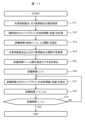
図1に、本発明のパイプライン管理システムの実施例1の概略構成を示し、図2に、本発明のパイプライン管理システムの実施例1における処理フローを示す。なお、本実施例では、図1に示す構成の全部を使用しているが、必ずしも全部を使用する必要はなく、一部を使用しても良い。 FIG. 1 shows a schematic configuration of a first embodiment of the pipeline management system of the present invention, and FIG. 2 shows a processing flow in the first embodiment of the pipeline management system of the present invention. In this embodiment, all of the configuration shown in FIG. 1 is used, but it is not necessary to use all of it, and a part of it may be used.
本実施例では、パイプライン管理装置5を用いたパイプライン管理システム100Aについて説明する。また、本実施例では、ガスパイプライン1に、水素供給拠点2、需要家のガス利用拠点3が接続されたガスグリッドを対象に、天然ガス102と水素ガス101の混合ガスを供給する例について説明する。 In this embodiment, a
図1に示すように、本実施例のパイプライン管理システム100Aは、需要家のガス利用拠点3が、ガス分離システム4を介してガスパイプライン1に接続されている。なお、本実施例では、天然ガス102と水素ガス101との混合ガスを想定したが、混合するガスは、密度の異なるガスであれば水素ガスと天然ガスに限定しない。また、混合するガスは、2種類に限定されるものではなく、2種類以上としても良い。 As shown in FIG. 1, in the
上述した水素供給拠点2は、ガスパイプライン1に水素ガス101を供給する機能を持つ施設及び設備を備えている。この水素供給拠点2の水素ガス101は、水素供給拠点2で製造されたものでも、他の場所で製造されたものでも良い。 The
天然ガス102が充填されているガスパイプライン1に、水素供給拠点2から水素ガス101を注入し、混合ガス103としてガス分離システム4を介して需要家のガス利用拠点3に供給される。
需要家のガス利用拠点3では、ガスパイプライン1から必要量の水素ガス101と天然ガス102或いは混合ガス103を取り出し、返送ガス104をガスパイプライン1に戻す。ここで、返送ガス104は、ガス利用拠点3で使用しないガスである。例えば、ガス利用拠点3が水素ガス101のみを使用する場合には、天然ガス102のみを返送ガス104としても良いし、天然ガス102と使用する分量以外の水素ガス101を混合して、混合ガス103と異なるガス組成のガスを返送ガス104としてガスパイプライン1に戻しても良い。 At the gas usage base 3 of the consumer, a required amount of
本実施例のパイプライン管理装置5は、図3に示すように、演算部5A、判断部5B及び判断結果表示部5Cにより構成されている。演算部5Aは、ガスパイプライン1内のガス流速を算出するための流体情報取得部5A1及びパイプライン流速算出部5A2と、返送ガス流速を算出するためのガス利用情報取得部5A3と、ガス分離システム情報取得部5A4及び返送ガス流速算出部5A5と、パイプライン流速と返送ガス流速から流速比を算出する流速比算出部5A6とから概略構成されている。 As shown in FIG. 3, the
判断部5Bは、流速比の規定範囲を取得する流速比規定範囲取得部5B1と、流速比を基に返送可否を判断する返送可否判断部5B2とを備えている。判断結果表示部5Cは、返送可否判断部5B2の判断結果を表示する表示部である。表示部の一例を図4に示す。 The
図4に示すパイプライン管理システムの例は、図1に示すパイプライン管理システム100Aと略同様な構成だが、需要家のガス利用拠点(需要点)3として第1の需要家のガス利用拠点3aと第2の需要家のガス利用拠点3bを備えている。 The example of the pipeline management system shown in FIG. 4 has approximately the same configuration as the
図4に示すように、表示部としては、ガスグリッド上のガスパイプライン1の位置を表示する第1の表示部301と、ガス分離システム4のガスパイプライン1への返送ガス104の流速比を表示する第2の表示部302と、パイプライン管理装置5で得られたガスのガスパイプライン1への返送可否の判断結果、調整後の返送ガス104の流速、調整後の流速比、ガスの使用情報、ガスパイプライン1のガス組成のうち少なくとも1つを表示する第3の表示部303がある。 As shown in FIG. 4, the display section includes a
次に、本実施例のパイプライン管理システム100Aにおけるガス処理について、図2の処理フローと共に説明する。 Next, gas processing in the
パイプライン管理装置5では、ガスパイプライン1内の流体情報201と、需要家のガス利用拠点3でのガス利用情報202と、ガス分離システム4の処理情報203とを入力として、ガスパイプライン1のガス流速と返送ガス104のガス流速との比を算出する。 The
先ず、パイプライン管理装置5では、初めにガスパイプライン1内の流体情報201を取得する(図2のS1)。ここで、ガスパイプライン1内の流体情報201とは、ガスパイプライン1内の任意の点の流速、流量、圧力、組成である。任意の点は、1つでも良いし、複数でも良い。 First, the
ガスパイプライン1内の流体情報201は、圧力計や流量計などのセンサにより直接計測しても良いし、ソフトセンサで算出しても良い。ソフトセンサとしては、例えば、ガスグリッド内の任意の2点での圧力の差分から流速や流量を算出すること、或いはガスグリッドに接続されているすべてのガス利用拠点でのガス使用量から流速や流量を算出すること、などが該当する。 The
需要家のガス利用拠点3でのガス利用情報202とは、需要家のガス利用拠点3のガス使用量である。ガス使用量は、1時間毎など定期的に情報を取得しても良いし、今後の使用予定量を情報として取得しても良い。 The
ガス分離システム4の処理情報203とは、ガス分離システム4の仕様に基づく処理性能であり、より具体的にはガスの分離に要する処理速度である。 The
次に、ガスパイプライン1内の流体情報からガスパイプライン1内のガスの流速を算出する(図2のS2)。 Next, the flow velocity of gas in the gas pipeline 1 is calculated from the fluid information in the gas pipeline 1 (S2 in FIG. 2).
次に、ガス分離システム4の処理情報203からガスパイプライン1内のガス組成及び需要家のガス利用拠点3で要求されるガス組成と量(流量)を取得する(図2のS3)。ガスパイプライン1内のガス組成、需要家のガス利用拠点3で要求されるガス組成と量を基に、ガス分離システム4から返送される返送ガス量を算出して返送ガス量が定まる(図2のS4)。 Next, from the
返送ガス量と、ガスパイプライン1へガスを返送する機構の構造(口径)とから返送ガスの流速を算出する(図2のS5)。ガスパイプライン1内の流体情報201から算出したガス流速と、返送ガス流速との比を算出する(図2のS6)。 The flow rate of the return gas is calculated from the return gas amount and the structure (caliber) of the mechanism that returns the gas to the gas pipeline 1 (S5 in FIG. 2). The ratio between the gas flow rate calculated from the
また、パイプライン管理装置5では、ガスパイプライン1内のガス流速(Vpipe)と返送ガス流速(Vreturn)との比(Vpipe/Vreturn)から返送可否を判定し、返送可否判断結果204として出力する。 In addition, the
予め定められた流速比の規定範囲を取得し(図2のS7)、流速の比(Vpipe/Vreturn)が予め定められた流速比の規定範囲内であれば返送可とし、ガスをガスパイプライン1に返送し、予め定められた規定の範囲を下回るか、或いは超過する場合には返送不可とし(図2のS8)、後述する返送流速調整機構8でガス流速を調整してパイプライン1に返送する。 A predetermined range of the flow rate ratio is obtained (S7 in FIG. 2), and if the flow rate ratio (Vpipe/Vreturn) is within the predetermined range of the flow rate ratio, return is possible, and the gas is transferred to the gas pipeline 1. If the gas falls below or exceeds a predetermined range, the gas cannot be returned (S8 in FIG. 2), and the gas flow rate is adjusted by a return flow
また、パイプライン管理装置5では、流速の比(Vpipe/Vreturn)を使用するが、比の分母と分子を逆転させ、ガスパイプライン1のガス流速に対する返送ガス104の流速(Vpipe/Vreturn)としても良い。また、流速比に準ずる指標として、運動量比、圧力比を指標としても良い。流速の比又は運動量比、圧力比の規定範囲は、予め流体シミュレーション又は実験により定めておく。 In addition, although the
流速比が上限閾値よりも大きい場合、つまり、ガスパイプライン1の流速に対して返送ガス104の流速(Vpipe/Vreturn)が小さい場合には、ガスパイプライン1とガス分離システム4をつなぐ接続管内に、ガスパイプライン1内のガスが逆流する可能性がある。これにより、接続管内に渦流が発生し、劣化が早まる懸念がある。 When the flow velocity ratio is larger than the upper limit threshold, that is, when the flow velocity of the return gas 104 (Vpipe/Vreturn) is smaller than the flow velocity of the gas pipeline 1, in the connecting pipe connecting the gas pipeline 1 and the gas separation system 4, There is a possibility that the gas in the gas pipeline 1 will flow back. As a result, there is a concern that vortices will occur within the connecting pipe, leading to faster deterioration.
また、接続管内に返送ガスが滞留してガスパイプライン1内のガス組成と差異が生じ、ガスパイプライン1内にガス濃度の不均一が発生する。そのため、流速比が上限閾値よりも大きい場合には、返送不可と判断する。 Further, the return gas remains in the connecting pipe, causing a difference in gas composition from the gas composition in the gas pipeline 1, resulting in non-uniform gas concentration in the gas pipeline 1. Therefore, if the flow velocity ratio is larger than the upper limit threshold, it is determined that the product cannot be returned.
流速比が下限閾値よりも小さい場合、つまり、ガスパイプライン1の流速に対して返送ガス104の流速(Vpipe/Vreturn)が大きい場合には、ガスパイプライン1中に旋回流が発生する可能性がある。これにより、ガスパイプライン1に力学的な負荷が生じる。そのため、流速比が下限閾値よりも小さい場合には、返送不可と判断する。 If the flow velocity ratio is smaller than the lower threshold, that is, if the flow velocity of the return gas 104 (Vpipe/Vreturn) is greater than the flow velocity of the gas pipeline 1, a swirling flow may occur in the gas pipeline 1. . This creates a mechanical load on the gas pipeline 1. Therefore, if the flow velocity ratio is smaller than the lower limit threshold, it is determined that the product cannot be returned.
また、パイプライン管理装置5では、返送可否判断結果204を出力してガス分離システム4に入力し、ガス分離システム4では、返送可否判断結果204が「可」の場合には、ガスパイプライン1にガスを返送し、一方、返送可否判断結果204が「不可」の場合には、バルブを閉めたり装置の運転を止めることにより、ガス返送を中止或いは返送ガスの流速を調整して返送するようにしている。 In addition, the
このような本実施例によれば、ガス分離システム4からのガスグリッドへの返送ガスの返送状態を適切に制御でき、ガスグリッドとガス分離システム4の劣化防止、ガスグリッド内のガス濃度の偏在を低減することができる。 According to this embodiment, it is possible to appropriately control the state of return gas from the gas separation system 4 to the gas grid, prevent deterioration of the gas grid and the gas separation system 4, and prevent uneven distribution of gas concentration in the gas grid. can be reduced.
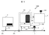
図5に、本発明のパイプライン管理システムの実施例2を示す。 FIG. 5 shows a second embodiment of the pipeline management system of the present invention.
図5に示す本実施例のパイプライン管理システム100Bは、実施例1に記載のパイプライン管理システム100Aに貯留タンク6を新たに設け、この貯留タンク6を用いて、パイプライン管理システム100Bにおいての返送「不可」と判断した場合に、返送ガス104の流速を調整するようにしたものである。 The
即ち、本実施例では、図5に示すように、実施例1に記載のガス分離システム4に接続された貯留タンク6を備えており、ガス分離システム4からの返送ガス104は、一度貯留タンク6に保持され、その後、貯留タンク6からガスパイプライン1へ返送されることになる。 That is, as shown in FIG. 5, this embodiment includes a
本実施例のパイプライン管理システム100Bは、貯留タンク6の圧力情報に基づいてパイプライン管理装置5のパイプライン流速算出部5A2で、ガスパイプライン1へ返送ガス104を返送する際の流速を算出し、流速の比(Vpipe/Vreturn)が予め規定された範囲内に保たれる場合は、ガスパイプライン1へのガス返送を行う。 In the
具体的には、流速の比(Vpipe/Vreturn)が予め規定された範囲内に保たれる場合にはガスパイプライン1に設置されている弁7を開とし、貯留タンク6からガスパイプライン1へのガス返送を行い、流速の比(Vpipe/Vreturn)が規定範囲の上限値を超過する場合には弁7を閉とし、貯留タンク6からガスパイプライン1へのガス返送は行わない。 Specifically, when the flow rate ratio (Vpipe/Vreturn) is maintained within a predetermined range, the valve 7 installed in the gas pipeline 1 is opened, and the flow from the
また、流速の比(Vpipe/Vreturn)が規定範囲の下限値を下回る場合には弁7を開とし、貯留タンク6からガスパイプライン1へのガス返送を行うが、その際、弁7の開度を調整して貯留タンク6からガスパイプライン1への返送ガス104の流速を調整している。 In addition, when the flow rate ratio (Vpipe/Vreturn) is less than the lower limit of the specified range, the valve 7 is opened and gas is returned from the
また、図5では、ガス分離システム4は、返送ガス104を、貯留タンク6を介してガスパイプライン1へ返送しているが、流速の比(Vpipe/Vreturn)が規定範囲内の時は、貯留タンク6を介さず直接ガス分離システム4からガスパイプライン1へ返送ガス104を返送しても良い。 In addition, in FIG. 5, the gas separation system 4 returns the
また、流速の比(Vpipe/Vreturn)が規定範囲の上限値を超過する場合には、ガス分離システム4からの返送ガス104と貯留タンク6内の返送ガスを混合してガスパイプライン1へ返送しても良い。 Furthermore, if the flow velocity ratio (Vpipe/Vreturn) exceeds the upper limit of the specified range, the
その場合、本実施例のパイプライン管理システム100Bでは、流速の比が規定範囲となるよう、ガス分離システム4からの返送ガス104の流量を基に、貯留タンク6の弁7の開度を算出し設定する。 In that case, in the
具体的には、流速の比の目標値(規定範囲の上限値)となる返送ガス104の目標流速を算出し、返送ガス104の目標流速を得るために必要なガス流量を接続管の口径から算出する。必要なガス流量からの、ガス分離システム4からの返送ガスの流量を差し引いた値を、補填ガス流量として算出する。補填ガス流量を満たすように、弁7の開度を調整して貯留タンク6から相当分の流量でガスを返送する。 Specifically, the target flow rate of the
なお、貯留タンク6からガスパイプライン1の間に逆止弁を設置し、ガスパイプライン1から貯留タンク6への逆流を防止しても良い。 Note that a check valve may be installed between the
このような本実施例によれば、ガス分離システム4からのガスグリッドへの返送ガス104の返送状態を適切に制御でき、ガスグリッドとガス分離システム4の劣化防止、ガスグリッド内のガス濃度の偏在を低減することができる。 According to this embodiment, it is possible to appropriately control the return state of the
図6(a)及び図6(b)に、本発明のパイプライン管理システムの実施例3を示す。 Embodiment 3 of the pipeline management system of the present invention is shown in FIGS. 6(a) and 6(b).
図6(a)及び図6(b)に示す本実施例のパイプライン管理システム100Cは、実施例1に記載のパイプライン管理システム100Aに返送流速調整機構8を設置し、この返送流速調整機構8を用いて、パイプライン管理システム100Cにおいて返送「不可」と判断した場合に、返送ガスの流速を調整するようにしたものである。 A
本実施例では、図6(a)に示すように、実施例1に記載のガス分離システム4に接続した返送流速調整機構8を備えている。 In this example, as shown in FIG. 6(a), a return flow
この返送流速調整機構8は、図6(b)に示すように、ガス分離システム4に接続された返送ガス104が流れている主接続管9と、主接続管9に接続された複数の分岐管10a、10b、10c及び10dから成る。複数の分岐管10a、10b、10c及び10dは、それぞれ個別に開閉を設定できるように開閉弁11a、11b、11c及び11dを備えている。 As shown in FIG. 6(b), this return flow
本実施例のパイプライン管理システム100Cは、ガス分離システム4の返送ガス104の流量からガスパイプライン1へ返送する際の流速を算出し、流速の比(Vpipe/Vreturn)が規定範囲となるように使用する分岐管10の本数を決定する。 The
例えば、ガス流速の比の規定範囲r1~r2に対して、管径Dの分岐管10をN本備える調整機構に対し、以下の(1)式を満たすよう使用する分岐管10の本数M(M≦N)を設定する。ここで、Qreturnは、ガス分離システム4から返送される返送ガス104の流量である。 For example, for an adjustment mechanism equipped with

なお、分岐管10の管径Dは、同一としても良いし、異なる管径としても良い。異なる管径の場合は、使用する分岐管10の本数と、管径Dから算出される分岐管10の断面積から使用する分岐管10と本数を決定する。 Note that the pipe diameters D of the
このような本実施例によれば、ガス分離システム4からのガスグリッドへの返送ガス104の返送状態を適切に制御でき、ガスグリッドとガス分離システム4の劣化防止、ガスグリッド内のガス濃度の偏在を低減することができる。 According to this embodiment, it is possible to appropriately control the return state of the
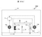
図7に、本発明のパイプライン管理システムの実施例4を示す。 FIG. 7 shows a fourth embodiment of the pipeline management system of the present invention.
図7に示す本実施例のパイプライン管理システム100Dは、実施例3に記載の返送流速調整機構8として、ガスパイプライン1内のガスを抜き出す抜出管12にガス分離システム4の返送ガス104と混和するためのバイパス管13が接続されているものである。 The
本実施例のパイプライン管理システム100Dでは、図7に示すように、ガスパイプライン1内のガスを抜き出す抜出管12に、ガス分離システム4の返送ガス104と混和するためのバイパス管13が接続されている返送流速調整機構8を備えている。 In the
そして、ガス流速の比(Vpipe/Vreturn)が規定範囲の上側値を超過する場合には、抜出管12に接続されたバイパス管13を介して抜出ガスの一部を返送管16に合流させる。 If the gas flow velocity ratio (Vpipe/Vreturn) exceeds the upper value of the specified range, a part of the extracted gas is merged into the
本実施例のパイプライン管理システム100Dでは、弁15を開としポンプ14により抜出ガスを返送管16に送る。ガス分離システム4からの返送ガス流量(Qreturn)とバイパス管13から送る抜出ガス流量(Qbypass)の合計が以下の(2)式を満たすよう、バイパス管13から送る抜出ガスの流量を調整する。 In the

ここで、Dは返送管16の管径である。流速の比が規定範囲の上側を超過していない場合は、弁15を閉とし返送ガス104のみをガスパイプライン1に返送する。 Here, D is the diameter of the
このような本実施例によれば、ガス分離システム4からのガスグリッドへの返送ガス104の返送状態を適切に制御でき、ガスグリッドとガス分離システム4の劣化防止、ガスグリッド内のガス濃度の偏在を低減することができる。 According to this embodiment, it is possible to appropriately control the return state of the
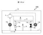
図8(a)及び図8(b)に、本発明のパイプライン管理システムの実施例5を示す。
図8(a)及び図8(b)に示す本実施例のパイプライン管理システム100Eは、実施例3の返送流速調整機構8の代わりに、返送位置切替機構19を備えているものである。 The
本実施例でのガスパイプライン1内のガス流速は、ガスパイプライン1に接続された各需要点でのガス抜出をドライビングフォースとして決定される。そのため、各需要点でのガス抜出の位置関係によっては、想定していたガスパイプライン1の流れと逆の向きに流れが生じることがある。 The gas flow rate within the gas pipeline 1 in this embodiment is determined by using the driving force of gas discharge at each demand point connected to the gas pipeline 1. Therefore, depending on the positional relationship of gas extraction at each demand point, a flow may occur in the opposite direction to the expected flow in the gas pipeline 1.
本実施例では、図8(a)及び図8(b)に示すように、返送位置切替機構19を備えている。なお、本実施例では、大元のガス供給点は、ガスパイプライン1の左側に繋がっており、通常のガスパイプライン1の流れが左から右に進む場合について説明する。 In this embodiment, as shown in FIGS. 8(a) and 8(b), a return
本実施例のガスパイプライン1には、図8(a)に示すように、2本の分岐抜出管17a及び17bと、この分岐抜出管17a及び17bが合流する抜出管12(抜出管12の矢印は、抜出したガスが混合ガス103に流れることを示す)、返送管16(返送管16の矢印は、返送ガス104が流れてくることを示す)が接続されており、これらを介してガス分離システム4へのガス移動が行われる。位置関係は、図8(a)の左(上流)側から分岐抜出管17a、返送管16、分岐抜出管17bとなる。 As shown in FIG. 8(a), the gas pipeline 1 of this embodiment includes two
本実施例の返送位置切替機構19では、パイプライン管理装置5の流速比算出部5A6で算出した流速比を基に、ポンプ14a及び14bを切り替えることで、2本の分岐抜出管17a及び17bのうちのいずれかを用いてガス抜出を行うか決定する。 In the return
通常のガスパイプライン1の流れ方向(左から右)に沿ってガスが流れている場合、ガスパイプライン1の流速は正の値をとる。一方、ガスの流れが逆転している場合(右から左)は、ガスパイプライン1の流速は負の値となる。そのため、流速比は、流れが順方向(左から右)の場合は正、逆方向(右から左)の場合は負の値となる。 When gas is flowing along the normal flow direction (left to right) of the gas pipeline 1, the flow velocity of the gas pipeline 1 takes a positive value. On the other hand, when the gas flow is reversed (from right to left), the flow velocity in the gas pipeline 1 takes a negative value. Therefore, the flow velocity ratio has a positive value when the flow is in the forward direction (from left to right), and a negative value when the flow is in the reverse direction (from right to left).
本実施例のパイプライン管理システム100Eでは、流速比が正の場合は、図8(a)に示すように、ガスパイプライン1の上流側からガスを抜き出し、ガスパイプライン1の下流側にガスを返送するため、分岐抜出管17aを用いてガスパイプライン1からガスを抜き出すようポンプ14aに指令を送る。 In the
一方、流速比が負の場合は、分岐抜出管17bが返送管16の上流に位置するため、ポンプ14bに指令を送り、分岐抜出管17bを用いてガスパイプライン1からガスを抜き出す。上述のように、常にガスパイプライン1の上流側でガスを抜き出し、下流側でガスを返送するよう切替制御を行う。 On the other hand, when the flow velocity ratio is negative, since the
位置関係が逆、即ち、上流側にガスを返送し、下流側でガスを抜き出すと返送ガス104が抜出ガスに混入する懸念がある。 If the positional relationship is reversed, that is, the gas is returned to the upstream side and the gas is extracted from the downstream side, there is a concern that the returned
しかし、本実施例の返送位置切替機構19では、常に上流側からガスを抜き出すことで、返送ガス104が抜出ガスに混入し、抜出ガスの濃度が不安定となることを防ぐことができる。 However, in the return
また、本実施例の返送位置切替機構19は、図8(b)に示すように、抜出管12と、2本の分岐返送管17a及び17bと、この分岐返送管17a及び17bに返送ガス104を供給する返送管16との構成にしても良い。この場合には、流速比の正負から分岐返送管17a及び17bのうち、抜出管12の下流に位置する分岐返送管17bを判別し、使用する分岐返送管17aを決定する。 Further, as shown in FIG. 8(b), the return
また、本実施例の返送位置切替機構19は、2本の分岐返送管17a及び17bを用意し、それぞれ切替弁18a及び18bを介して抜出管12と返送管16の両方に繋ぐ構成としても良い。 The return
これにより、流速比の正負からガスパイプライン1の上流側に位置する分岐抜出管17aから抜出管12へ抜出ガスを送り、下流側に位置する分岐抜出管17bへ返送管16から返送ガス104を送るように、パイプライン管理装置5で切替弁18a及び18bを制御できる。 As a result, the extracted gas is sent from the
このような本実施例によれば、実施例3と同様な効果が得られることは勿論、ガスグリッド内の流れ方向が逆転した場合にも、ガスパイプライン1の上流からガスを抜き出し、下流から返送ガス104を送り込むことができ、返送ガス104が抜出ガスに混和することを防止できる。 According to this embodiment, not only can the same effects as in embodiment 3 be obtained, but also when the flow direction in the gas grid is reversed, gas can be extracted from the upstream of the gas pipeline 1 and returned from the downstream. The
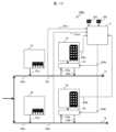
図9に、本発明のパイプライン管理システムの実施例6を示す。 FIG. 9 shows a sixth embodiment of the pipeline management system of the present invention.
図9に示す本実施例のパイプライン管理システム100Fは、実施例3の返送流速調整機構8として、複数のガス分離システム4a及び4bのそれぞれからの返送ガス104a及び104bを合流させて返送する集合管20を備えているものである。 The
本実施例のパイプライン管理システム100Fでは、図9に示すように、複数のガス分離システム4a及び4bの返送ガス104a及び104bを集合管20で合流させてガスパイプライン1に返送している。 In the
なお、図9では、2台のガス分離システム4a及び4bの返送ガス104a及び104bを合流させているが、台数は2台に限らない。 In addition, although the
このような本実施例によれば、実施例3と同様な効果が得られることは勿論、ガス分離システム4a及び4bでの処理量が少なく、返送ガス104a及び104bの流量が不十分な場合にも、適切に返送ガスをガスパイプライン1に返送することができる。 According to this embodiment, not only can the same effects as in embodiment 3 be obtained, but also when the throughput in the
図10及び図11に、本発明のパイプライン管理システムの実施例7を示す。 Embodiment 7 of the pipeline management system of the present invention is shown in FIGS. 10 and 11.
図10に示す本実施例のパイプライン管理システム100Gは、実施例1に記載のパイプライン管理システム100Aに入力するガスパイプライン1内の流体情報201を、シミュレーションにより入手ものである。 The
図10に、本実施例のパイプライン管理システム100Gにおけるガスパイプライン1a及び1b内の流体情報201を、シミュレーションにより入手する場合のシステム構成図を示し、図11に、評価時間t1~tnの間のガスグリッド内の流体情報201を算出する場合の処理フローを示す。 FIG. 10 shows a system configuration diagram when the
本実施例では、ガスグリッドに接続されたガスパイプライン1a及び1bの流体情報201a及び201bは、予め取得した管路・ガス注入機構形状情報と需要点でのガス抜出量、返送量、供給点でのガス注入量を入力として算出する。ここで、需要点でのガス抜出量、返送量、供給点でのガス注入量は、オンラインで現時刻の情報を取得しても良いし、予め数時刻先の予定が判明している場合には予定に基づき算出しても良い。 In this embodiment, the
本実施例のパイプライン管理システム100Gにおけるガス処理について、図11の処理フローを用いて説明する。 Gas processing in the
先ず、ガスグリッド内に接続されている水素供給拠点2及び需要家のガス利用拠点(需要点)3の数を取得し(S11)、予め取得した管路・ガス注入機構形状情報を入力として、現在のガスグリッド内の対象のガスパイプライン1の流体情報(ガス流量)を計算する(S12)。 First, the number of
次に、評価時間(時刻t1~tn、Δt間隔)を設定する(S13)。本実施例では、評価時間は現在時刻t1からtn時刻先までとし、評価間隔はΔtと設定した場合について説明する。 Next, an evaluation time (time t1 to tn, interval Δt) is set (S13). In this embodiment, a case will be described in which the evaluation time is set from the current time t1 to tn times ahead, and the evaluation interval is set to Δt.
次に、水素供給拠点2及び需要家のガス利用拠点(需要点)3の運転予定を取得する(S14)。ここで、運転予定とは、設定した評価時間t1~tnの間の水素供給拠点2における水素ガスの注入予定、需要点における混合ガスの抜出予定である。 Next, the operation schedule of the
水素ガスの注入予定とは、時刻に対する水素ガスの注入量、注入圧力、注入流量などの情報である。混合ガスの抜出予定とは、時刻に対する混合ガスの抜出量、抜出流量、需要点での混合ガスの成分に対する使用量などである。需要家のガス利用拠点(需要点)3での混合ガスの成分に対する使用量とは、混合ガス中に含まれる成分(水素ガス、天然ガス)毎の使用量である。需要家のガス利用拠点(需要点)3において、混合ガスをそのまま使用する場合には、ガス利用拠点での混合ガスの成分に対する使用量の合計は、混合ガスの使用量と一致する。 The hydrogen gas injection schedule is information such as the amount of hydrogen gas to be injected, the injection pressure, and the injection flow rate with respect to the time. The mixed gas extraction schedule includes the amount of mixed gas to be extracted with respect to time, the extraction flow rate, the usage amount of the mixed gas components at the demand point, and the like. The amount used for each component of the mixed gas at the consumer's gas usage base (demand point) 3 is the amount used for each component (hydrogen gas, natural gas) included in the mixed gas. When the mixed gas is used as it is at the gas usage base (demand point) 3 of the consumer, the total usage amount of the components of the mixed gas at the gas usage base matches the usage amount of the mixed gas.
一方、需要家のガス利用拠点(需要点)3で特定の成分のみ使用する場合には、使用しない成分をガスパイプライン1に返送ガス104として返送するため、混合ガスの成分に対する使用量の合計は、混合ガスの使用量から返送ガス量を差し引いた値と一致する。混合ガスの抜出予定と、予め取得した管路・ガス注入機構形状情報を入力として、評価時間t1~tn間の返送ガスの予定を算出する(S15及びS16)。 On the other hand, when only a specific component is used at the consumer's gas usage base (demand point) 3, the unused components are returned to the gas pipeline 1 as
次に、現時刻のガスグリッド内の流体情報と、評価時間t1~tnの間の水素ガスの注入予定、混合ガスの抜出予定、返送ガスの返送予定と、予め取得した管路情報を入力として、評価時間t1~tnの間のガスグリッド内の対象ガスパイプライン1a又は1bの流速を計算する(S17、S18、S19)。算出した対象ガスパイプライン1a又は1bの流速を、パイプライン管理装置5で用いるガスパイプライン1の流体情報として使用する。 Next, input the fluid information in the gas grid at the current time, the hydrogen gas injection schedule, the mixed gas extraction schedule, the return gas return schedule, and the pipeline information obtained in advance during the evaluation time t1 to tn. , the flow velocity of the
このような本実施例によれば、ガスパイプライン1内の流体情報201の計測が困難な場合であっても、ガスパイプライン1内の流体情報201を取得でき、ガスグリッドへの返送ガス104の返送状態を適切に制御でき、ガスグリッドとガス分離システム4の劣化防止、ガスグリッド内のガス濃度の偏在を低減することができる。 According to this embodiment, even if it is difficult to measure the
本実施例は、特に、ガスパイプライン1が広域にわたるガスグリッドに接続されている場合に有効である。 This embodiment is particularly effective when the gas pipeline 1 is connected to a gas grid over a wide area.
なお、本発明は上述した実施例に限定されるものではなく、様々な変形例が含まれる。例えば、上述した実施例は本発明を分かりやすく説明するために詳細に説明したものであり、必ずしも説明したすべての構成を備えるものに限定されるものではない。また、ある実施例の構成の一部を他の実施例の構成に置き換える事が可能であり、また、ある実施例の構成に他の実施例の構成を加える事も可能である。また、各実施例の構成の一部について、他の構成の追加・削除・置換をする事が可能である。 Note that the present invention is not limited to the embodiments described above, and includes various modifications. For example, the embodiments described above are described in detail to explain the present invention in an easy-to-understand manner, and the present invention is not necessarily limited to having all the configurations described. Furthermore, it is possible to replace a part of the configuration of one embodiment with the configuration of another embodiment, and it is also possible to add the configuration of another embodiment to the configuration of one embodiment. Furthermore, it is possible to add, delete, or replace a part of the configuration of each embodiment with other configurations.
1、1a、1b…ガスパイプライン、2…水素供給拠点、3…需要家のガス利用拠点(需要点)、3a…第1の需要家のガス利用拠点、3b…第2の需要家のガス利用拠点、4、4a、4b…ガス分離システム、5…パイプライン管理装置、5A…演算部、5A1…流体情報取得部、5A2…パイプライン流速算出部、5A3…ガス利用情報取得部、5A4…ガス分離システム情報取得部、5A5…返送ガス流速算出部、5A6…流速比算出部、5B…判断部、5B1…流速比規定範囲取得部、5B2…返送可否判断部、5C…判断結果表示部、6…貯留タンク、7、15…弁、8…返送流速調整機構、9…主接続管、10、10a、10b、10c、10d…分岐管、11a、11b、11c、11d…開閉弁、12…抜出管、13…バイパス管、14、14a、14b…ポンプ、16…返送管、17a、17b…分岐抜出管、18a、18b…切替弁、19…返送位置切替機構、20…集合管、100A、100B,100C、100D、100E、100F、100G…パイプライン管理システム、101…水素ガス、102…天然ガス、103…混合ガス、104、104a、104b……返送ガス、201、201a、201b…ガスパイプライン内の流体情報、202…需要家のガス利用拠点でのガス利用情報、203…ガス分離システムの処理情報、204…返送可否判断結果、301…第1の表示部、302…第2の表示部、303…第3の表示部。 1, 1a, 1b...gas pipeline, 2...hydrogen supply base, 3...consumer's gas usage base (demand point), 3a...first consumer's gas usage base, 3b...second consumer's gas usage Base, 4, 4a, 4b...Gas separation system, 5...Pipeline management device, 5A...Computation unit, 5A1...Fluid information acquisition unit, 5A2...Pipeline flow rate calculation unit, 5A3...Gas usage information acquisition unit, 5A4...Gas Separation system information acquisition section, 5A5...Return gas flow velocity calculation section, 5A6...Flow velocity ratio calculation section, 5B...Judgment section, 5B1...Flow velocity ratio specified range acquisition section, 5B2...Return propriety judgment section, 5C...Judgment result display section, 6 ...Storage tank, 7, 15...Valve, 8...Return flow rate adjustment mechanism, 9...Main connection pipe, 10, 10a, 10b, 10c, 10d...Branch pipe, 11a, 11b, 11c, 11d...Opening/closing valve, 12...Extraction Output pipe, 13...Bypass pipe, 14, 14a, 14b...Pump, 16...Return pipe, 17a, 17b...Branch extraction pipe, 18a, 18b...Switching valve, 19...Return position switching mechanism, 20...Collecting pipe, 100A , 100B, 100C, 100D, 100E, 100F, 100G...pipeline management system, 101...hydrogen gas, 102...natural gas, 103...mixed gas, 104, 104a, 104b...return gas, 201, 201a, 201b...gas pipe Fluid information in the line, 202...Gas usage information at the consumer's gas usage base, 203...Processing information of the gas separation system, 204...Returnability determination result, 301...First display section, 302...Second display Section, 303...Third display section.
Claims (20)
Translated fromJapanese前記パイプライン管理装置では、前記ガスパイプラインと返送ガスの流速比から前記ガスの前記ガスパイプラインへの返送可否を判断し、前記ガスの流速比が予め規定された範囲内となるように前記返送ガスの流速を制御することを特徴とするパイプライン管理システムの制御方法。A method for controlling a pipeline management system according to claim 1, comprising:
The pipeline management device determines whether or not the gas can be returned to the gas pipeline based on the flow velocity ratio between the gas pipeline and the return gas, and controls the return gas so that the flow velocity ratio of the gas is within a predefined range. A method for controlling a pipeline management system, the method comprising controlling the flow rate of a pipeline.
前記パイプライン管理装置では、前記ガスパイプライン内の流体情報と、需要家のガス利用拠点でのガス利用情報と、前記ガス分離システムの処理情報とを入力として、前記ガスパイプラインのガス流速と前記返送ガスのガス流速との比を算出することを特徴とするパイプライン管理システムの制御方法。A method for controlling a pipeline management system according to claim 1 or 2, comprising:
The pipeline management device inputs fluid information in the gas pipeline, gas usage information at the consumer's gas usage base, and processing information of the gas separation system, and calculates the gas flow rate in the gas pipeline and the return. A control method for a pipeline management system, characterized by calculating a ratio of gas to a gas flow rate.
前記ガスパイプライン内の前記流体情報とは、前記ガスパイプライン内の任意の点の流速、流量、圧力、組成であり、
前記需要家の前記ガス利用拠点での前記ガス利用情報とは、前記ガス利用拠点のガス使用量であり、
前記ガス分離システムの前記処理情報とは、前記ガス分離システムの仕様に基づく処理性能であることを特徴とするパイプライン管理システムの制御方法。A method for controlling a pipeline management system according to claim 3, comprising:
The fluid information in the gas pipeline is the flow rate, flow rate, pressure, and composition at any point in the gas pipeline,
The gas usage information at the gas usage base of the consumer is the gas usage amount at the gas usage base,
A method for controlling a pipeline management system, wherein the processing information of the gas separation system is processing performance based on specifications of the gas separation system.
前記ガスパイプライン内の流体情報を、センサ、ソフトセンサ、ガスグリッドを対象としたシミュレーションのいずれか、又はそれらを組み合わせて取得することを特徴とするパイプライン管理システムの制御方法。A method for controlling a pipeline management system according to claim 3 or 4, comprising:
A method for controlling a pipeline management system, characterized in that fluid information in the gas pipeline is obtained through a sensor, a soft sensor, a simulation targeting a gas grid, or a combination thereof.
前記パイプライン管理装置では、
前記ガスパイプライン内の前記流体情報を取得する工程(S1)と、
前記ガスパイプライン内の流体情報から前記ガスパイプライン内のガスの流速を算出する工程(S2)と、
前記ガス分離システムの処理情報から前記ガスパイプライン内のガス組成及び前記需要家のガス利用拠点で要求されるガス組成と量(流量)を取得する工程(S3)と、
前記ガスパイプライン内のガス組成、前記需要家のガス利用拠点で要求されるガス組成と量を基に、前記ガス分離システムから返送される返送ガス量を算出して返送ガス量を決める工程(S4)と、
前記返送ガス量と、前記ガスパイプラインへガスを返送する機構の構造とから前記返送ガスの流速を算出する工程(S5)と、
前記ガスパイプライン内の前記流体情報から算出したガス流速と返送ガス流速との比を算出する工程(S6)と、
予め定められた前記ガスの流速比の規定範囲を取得する工程(S7)と、
前記ガスパイプライン内のガス流速(Vpipe)と返送ガス流速(Vreturn)との比(Vpipe/Vreturn)が予め規定された範囲内であれば返送可とし、予め規定された範囲を下回るか、或いは超過する場合には返送不可とする工程(S8)とを、実行することを特徴とするパイプライン管理システムの制御方法。A method for controlling a pipeline management system according to claim 3, comprising:
In the pipeline management device,
a step (S1) of acquiring the fluid information in the gas pipeline;
a step (S2) of calculating a flow rate of gas in the gas pipeline from fluid information in the gas pipeline;
a step (S3) of acquiring the gas composition in the gas pipeline and the gas composition and amount (flow rate) required at the gas usage base of the consumer from the processing information of the gas separation system;
Step of determining the amount of return gas by calculating the amount of return gas returned from the gas separation system based on the gas composition in the gas pipeline and the gas composition and amount required at the gas usage base of the consumer (S4 )and,
calculating the flow rate of the return gas from the return gas amount and the structure of a mechanism for returning gas to the gas pipeline (S5);
a step (S6) of calculating a ratio between the gas flow rate calculated from the fluid information in the gas pipeline and the return gas flow rate;
a step (S7) of acquiring a predetermined range of the flow velocity ratio of the gas;
Return is allowed if the ratio (Vpipe/Vreturn) between the gas flow rate (Vpipe) and the return gas flow rate (Vreturn) in the gas pipeline is within a predefined range, and is below or exceeds the predefined range. A method for controlling a pipeline management system, characterized in that a step (S8) of disabling the return is performed if the return is prohibited.
前記ガスパイプラインと前記ガス分離システムの両方に接続された貯留設備へのガスの貯留と排出を制御することで、前記ガスパイプラインへの前記返送ガスの流速を制御することを特徴とするパイプライン管理システムの制御方法。A method for controlling a pipeline management system according to claim 2, comprising:
Pipeline management, characterized in that the flow rate of the return gas to the gas pipeline is controlled by controlling storage and discharge of gas to storage equipment connected to both the gas pipeline and the gas separation system. How to control the system.
前記ガス分離システムに接続された主接続管と、該主接続管に接続された複数の分岐管とから成る返送流速調整機構の前記分岐管の使用本数を変更することで、前記ガスパイプラインへの前記返送ガスの流速を制御することを特徴とするパイプライン管理システムの制御方法。A method for controlling a pipeline management system according to claim 2, comprising:
By changing the number of branch pipes used in the return flow rate adjustment mechanism, which consists of a main connection pipe connected to the gas separation system and a plurality of branch pipes connected to the main connection pipe, the flow rate to the gas pipeline can be changed. A method for controlling a pipeline management system, comprising controlling the flow rate of the return gas.
前記ガスパイプライン内のガスを抜き出す抜出管に、前記ガス分離システムの前記返送ガスと混和するためのバイパス管が接続されている返送流速調整機構により、前記バイパス管のガス流量を調整し、前記ガスパイプラインへの前記返送ガスの流速を制御することを特徴とするパイプライン管理システムの制御方法。A method for controlling a pipeline management system according to claim 2, comprising:
A return flow rate adjustment mechanism, in which a bypass pipe for mixing with the return gas of the gas separation system is connected to an extraction pipe for extracting gas in the gas pipeline, adjusts the gas flow rate of the bypass pipe, and A method for controlling a pipeline management system, comprising controlling the flow rate of the return gas to a gas pipeline.
前記ガスパイプラインに接続された2本の分岐抜出管と、2本の前記分岐抜出管が合流する抜出管と、前記返送ガスが流れてくる返送管とから成り、前記抜出管と前記返送管の位置関係を変更可能な返送位置切替機構により、前記ガスの流れ方向に対して上流側に前記抜出管、下流側に前記返送管が位置するよう切替制御することを特徴とするパイプライン管理システムの制御方法。A method for controlling a pipeline management system according to claim 1, comprising:
It consists of two branch extraction pipes connected to the gas pipeline, an extraction pipe where the two branch extraction pipes join, and a return pipe through which the return gas flows, and the extraction pipe and A return position switching mechanism capable of changing the positional relationship of the return pipes controls switching so that the extraction pipe is located on the upstream side and the return pipe is located on the downstream side with respect to the flow direction of the gas. How to control a pipeline management system.
前記パイプライン管理装置により、前記ガスパイプラインと返送ガスの流速比から前記ガスの前記ガスパイプラインへの返送可否を判断し、前記ガスの流速比が予め規定された範囲内であれば返送可とし、予め規定された範囲を下回るか、或いは予め規定された範囲を超過する場合には返送不可とすることを特徴とするパイプライン管理システム。a gas separation system that is connected to a gas pipeline and extracts the gas from the gas pipeline filled with gas and returns the gas to the gas pipeline; and a pipeline management in which at least fluid information of the gas pipeline is input. equipped with a device,
The pipeline management device determines whether the gas can be returned to the gas pipeline based on the flow velocity ratio of the gas pipeline and the return gas, and determines that the gas can be returned if the flow velocity ratio of the gas is within a predefined range; A pipeline management system characterized in that if the amount falls below a predefined range or exceeds a predefined range, the product cannot be returned.
前記パイプライン管理装置は、前記ガスパイプラインと返送ガスの流速比から前記ガスの前記ガスパイプラインへの返送可否を判断し、前記ガスの流速比が予め規定された範囲内となるように前記返送ガスの流速を制御することを特徴とするパイプライン管理システム。The pipeline management system according to claim 11,
The pipeline management device determines whether the gas can be returned to the gas pipeline based on the flow velocity ratio between the gas pipeline and the return gas, and controls the return gas so that the flow velocity ratio of the gas is within a predefined range. A pipeline management system characterized by controlling the flow rate of.
前記パイプライン管理装置は、演算部と判断部及び判断結果表示部を備え、
前記演算部は、前記ガスパイプライン内のガス流速を算出するための流体情報取得部及びパイプライン流速算出部と、前記返送ガスの流速を算出するためのガス利用情報取得部と、ガス分離システム情報取得部及び返送ガス流速算出部と、前記ガスパイプライン内のガス流速と前記返送ガスの流速から流速比を算出する流速比算出部とから成り、
前記判断部は、流速比の規定範囲を取得する流速比規定範囲取得部と、流速比を基に返送可否を判断する返送可否判断部とから成り、
前記判断結果表示部は、前記返送可否判断部の判断結果を表示する表示部であることを特徴とするパイプライン管理システム。The pipeline management system according to claim 11 or 12,
The pipeline management device includes a calculation section, a judgment section, and a judgment result display section,
The calculation unit includes a fluid information acquisition unit and a pipeline flow rate calculation unit for calculating the gas flow rate in the gas pipeline, a gas usage information acquisition unit for calculating the flow rate of the return gas, and gas separation system information. It consists of an acquisition unit, a return gas flow rate calculation unit, and a flow rate ratio calculation unit that calculates a flow rate ratio from the gas flow rate in the gas pipeline and the flow rate of the return gas,
The determination unit includes a flow rate ratio specified range acquisition unit that acquires the specified range of the flow rate ratio, and a return possibility determination unit that determines whether the return is possible based on the flow rate ratio,
The pipeline management system is characterized in that the determination result display unit is a display unit that displays the determination result of the returnability determination unit.
前記返送可否判断部の表示部は、
ガスグリッド上の前記ガスパイプラインの位置を表示する第1の表示部と、
前記ガス分離システムの前記ガスパイプラインへの前記返送ガスの流速比を表示する第2の表示部と、
前記パイプライン管理装置で得られたガスの前記ガスパイプラインへの返送可否の判断結果、調整後の前記返送ガスの流速、調整後の流速比、ガスの使用情報、前記ガスパイプラインのガス組成のうち少なくとも1つを表示する第3の表示部であることを特徴とするパイプライン管理システム。14. The pipeline management system according to claim 13,
The display section of the return determination section is as follows:
a first display section that displays the position of the gas pipeline on a gas grid;
a second display section that displays a flow rate ratio of the return gas to the gas pipeline of the gas separation system;
Among the results of the judgment as to whether or not the gas obtained by the pipeline management device can be returned to the gas pipeline, the adjusted flow rate of the returned gas, the adjusted flow rate ratio, gas usage information, and the gas composition of the gas pipeline. A pipeline management system characterized by being a third display section that displays at least one.
前記ガスパイプラインと前記ガス分離システムの両方に接続された貯留設備を備え、
前記貯留設備へのガス貯留と排出を制御することで、前記ガスパイプラインへの前記返送ガスの流速を制御することを特徴とするパイプライン管理システム。13. The pipeline management system according to claim 12,
a storage facility connected to both the gas pipeline and the gas separation system;
A pipeline management system characterized in that the flow rate of the return gas to the gas pipeline is controlled by controlling gas storage and discharge to the storage facility.
前記ガス分離システムに接続された主接続管と、該主接続管に接続された複数の分岐管とからなる返送流速調整機構を備え、
前記返送流速調整機構の前記分岐管の使用本数を変更することで、前記ガスパイプラインへの前記返送ガスの流速を制御することを特徴とするパイプライン管理システム。13. The pipeline management system according to claim 12,
A return flow rate adjustment mechanism comprising a main connecting pipe connected to the gas separation system and a plurality of branch pipes connected to the main connecting pipe,
A pipeline management system characterized in that the flow rate of the return gas to the gas pipeline is controlled by changing the number of branch pipes used in the return flow rate adjustment mechanism.
前記ガスパイプライン内のガスを抜き出す抜出管に、前記ガス分離システムの前記返送ガスと混和するためのバイパス管が接続されている返送流速調整機構を備え、
前記バイパス管のガス流量を調整し、前記ガスパイプラインへの前記返送ガスの流速を制御することを特徴とするパイプライン管理システム。13. The pipeline management system according to claim 12,
A return flow rate adjustment mechanism is provided in which a bypass pipe for mixing with the return gas of the gas separation system is connected to an extraction pipe for extracting gas in the gas pipeline,
A pipeline management system characterized by adjusting the gas flow rate of the bypass pipe and controlling the flow rate of the return gas to the gas pipeline.
前記ガスパイプラインに接続された2本の分岐抜出管と、2本の前記分岐抜出管が合流する抜出管と、前記返送ガスが流れてくる返送管とから成り、前記抜出管と前記返送管の位置関係を変更可能な返送位置切替機構を備え、
前記返送位置切替機構により、前記ガスの流れ方向に対して上流側に前記抜出管、下流側に前記返送管が位置するよう切替制御することを特徴とするパイプライン管理システム。13. The pipeline management system according to claim 12,
It consists of two branch extraction pipes connected to the gas pipeline, an extraction pipe where the two branch extraction pipes join, and a return pipe through which the return gas flows, and the extraction pipe and comprising a return position switching mechanism capable of changing the positional relationship of the return pipes,
A pipeline management system characterized in that the return position switching mechanism performs switching control such that the extraction pipe is located on the upstream side and the return pipe is located on the downstream side with respect to the flow direction of the gas.
前記ガスパイプラインに接続された2本の分岐抜出管と、2本の前記分岐抜出管が合流する抜出管と、前記返送ガスが流れてくる返送管とから成り、前記抜出管と前記返送管の位置関係を変更可能な返送位置切替機構を備え、
前記返送位置切替機構により、前記ガスの流れ方向に対して上流側に前記抜出管、下流側に前記返送管が位置するよう切替制御することを特徴とするパイプライン管理システムの制御方法。13. The pipeline management system according to claim 12,
It consists of two branch extraction pipes connected to the gas pipeline, an extraction pipe where the two branch extraction pipes join, and a return pipe through which the return gas flows, and the extraction pipe and comprising a return position switching mechanism capable of changing the positional relationship of the return pipes,
A control method for a pipeline management system, characterized in that the return position switching mechanism performs switching control such that the extraction pipe is located on the upstream side and the return pipe is located on the downstream side with respect to the flow direction of the gas.
前記ガス分離システムに接続された主接続管と、該主接続管に接続された複数の分岐管とからなる返送流速調整機構を備え、
前記返送流速調整機構は、複数のガス分離システムのそれぞれからの返送ガスを合流させて返送する集合管を備えていることを特徴とするパイプライン管理システム。The pipeline management system according to any one of claims 11 to 14,
A return flow rate adjustment mechanism comprising a main connecting pipe connected to the gas separation system and a plurality of branch pipes connected to the main connecting pipe,
A pipeline management system characterized in that the return flow rate adjustment mechanism includes a collecting pipe that combines the return gases from each of the plurality of gas separation systems and returns them.
Priority Applications (3)
| Application Number | Priority Date | Filing Date | Title |
|---|---|---|---|
| JP2022046822AJP2023140800A (en) | 2022-03-23 | 2022-03-23 | Pipeline management system and control method therefor |
| PCT/JP2022/047612WO2023181560A1 (en) | 2022-03-23 | 2022-12-23 | Pipeline management system and control method thereof |
| GB2412326.7AGB2631027A (en) | 2022-03-23 | 2022-12-23 | Pipeline management system and control method thereof |
Applications Claiming Priority (1)
| Application Number | Priority Date | Filing Date | Title |
|---|---|---|---|
| JP2022046822AJP2023140800A (en) | 2022-03-23 | 2022-03-23 | Pipeline management system and control method therefor |
Publications (1)
| Publication Number | Publication Date |
|---|---|
| JP2023140800Atrue JP2023140800A (en) | 2023-10-05 |
Family
ID=88100472
Family Applications (1)
| Application Number | Title | Priority Date | Filing Date |
|---|---|---|---|
| JP2022046822APendingJP2023140800A (en) | 2022-03-23 | 2022-03-23 | Pipeline management system and control method therefor |
Country Status (3)
| Country | Link |
|---|---|
| JP (1) | JP2023140800A (en) |
| GB (1) | GB2631027A (en) |
| WO (1) | WO2023181560A1 (en) |
Citations (2)
| Publication number | Priority date | Publication date | Assignee | Title |
|---|---|---|---|---|
| JP2002243100A (en)* | 2001-02-14 | 2002-08-28 | Tokyo Gas Co Ltd | City gas supply method and system |
| JP2019198221A (en)* | 2012-05-28 | 2019-11-14 | ハイドロジェニクス コーポレイション | Electrolyzer and energy system |
Family Cites Families (6)
| Publication number | Priority date | Publication date | Assignee | Title |
|---|---|---|---|---|
| JP4721525B2 (en)* | 2001-01-19 | 2011-07-13 | 東京瓦斯株式会社 | City gas supply method and apparatus |
| JP6407612B2 (en)* | 2014-08-04 | 2018-10-17 | 東京ガスエンジニアリングソリューションズ株式会社 | Decompression energy recovery device in gas pipeline |
| WO2020044424A1 (en)* | 2018-08-28 | 2020-03-05 | 東芝エネルギーシステムズ株式会社 | Hydrogen distribution planning device and hydrogen distribution planning method |
| JP2020047495A (en)* | 2018-09-20 | 2020-03-26 | トヨタ自動車株式会社 | Community system |
| JP2020060847A (en)* | 2018-10-05 | 2020-04-16 | トヨタ自動車株式会社 | Hydrogen supply and demand matching system |
| CN111992071B (en)* | 2020-08-13 | 2025-09-09 | 山西铭石煤层气利用股份有限公司 | Hydrogen energy utilization gas blending system and hydrogen and natural gas ratio control method |
- 2022
- 2022-03-23JPJP2022046822Apatent/JP2023140800A/enactivePending
- 2022-12-23WOPCT/JP2022/047612patent/WO2023181560A1/ennot_activeCeased
- 2022-12-23GBGB2412326.7Apatent/GB2631027A/enactivePending
Patent Citations (2)
| Publication number | Priority date | Publication date | Assignee | Title |
|---|---|---|---|---|
| JP2002243100A (en)* | 2001-02-14 | 2002-08-28 | Tokyo Gas Co Ltd | City gas supply method and system |
| JP2019198221A (en)* | 2012-05-28 | 2019-11-14 | ハイドロジェニクス コーポレイション | Electrolyzer and energy system |
Also Published As
| Publication number | Publication date |
|---|---|
| GB2631027A (en) | 2024-12-18 |
| WO2023181560A1 (en) | 2023-09-28 |
Similar Documents
| Publication | Publication Date | Title |
|---|---|---|
| Moazeni et al. | Maximizing energy efficiency of islanded micro water-energy nexus using co-optimization of water demand and energy consumption | |
| Li et al. | Solving natural gas loadflow problems using electric loadflow techniques | |
| CN110851960A (en) | A reliability assessment method for distribution network operation considering the influence of natural gas network | |
| CN109357310A (en) | Emergency treatment system for safety and economical operation of heat pipe network | |
| CN216260077U (en) | Gas mixing hydrogen system | |
| Stennikov et al. | Use of multilevel modeling for determining optimal parameters of heat supply systems | |
| Lejano | Optimizing the layout and design of branched pipeline water distribution systems | |
| JP2023140800A (en) | Pipeline management system and control method therefor | |
| AbdelMeguid et al. | Pressure and leakage management in water distribution systems via flow modulation PRVs | |
| WO2024247948A1 (en) | Mixed gas grid management system and mixed gas grid management method | |
| CN112050273B (en) | A virtual energy storage control method for hot water pipe network based on quasi-dynamic delay characteristics | |
| Malamura et al. | Hybrid system modeling and operation schedule optimization for gas transportation network based on combined method of DE, GA and hybrid petri net | |
| Mazouz et al. | Analysis of The Simulation of The Water Supply Network of The New City of Guelma by Epanet | |
| Sandou et al. | Global modelling and simulation of a district heating network | |
| Vieira et al. | Optimization of the energy management in water supply systems | |
| WO2022230123A1 (en) | Hydrogen supply and demand system and hydrogen supply and demand method | |
| Bykov et al. | Power Flow Optimization Problems for Multi-Energy Systems | |
| JP3540738B2 (en) | Flow distribution device | |
| US20140013757A1 (en) | Solar Thermal Gas Turbine System | |
| Rintoul et al. | Modelling Water Distribution Networks to Determine Potential Energy Recovery Using ESP‐R | |
| Briceño-León et al. | Pumping Station Design with an Analysis of Variability of Demand and Considering Techno-Economic and Environmental Criteria through the AHP Method | |
| Wang et al. | Operational Risk for Integrated Power and Gas Systems Considering Varying Hydrogen Concentrations With High Penetration of Wind | |
| Francesconi et al. | Impact of hydrogen blending on a real-world gas distribution network with a non-uniform elevation profile | |
| Modisette | Dynamic Pump and Tank Optimizer for Water Networks | |
| Hochmeister et al. | CO2 Transport via Pipelines: Design of CO2 networks using an Optimal Power Flow approach |
Legal Events
| Date | Code | Title | Description |
|---|---|---|---|
| A621 | Written request for application examination | Free format text:JAPANESE INTERMEDIATE CODE: A621 Effective date:20240618 | |
| A131 | Notification of reasons for refusal | Free format text:JAPANESE INTERMEDIATE CODE: A131 Effective date:20250729 | |
| A521 | Request for written amendment filed | Free format text:JAPANESE INTERMEDIATE CODE: A523 Effective date:20250827 | |
| A01 | Written decision to grant a patent or to grant a registration (utility model) | Free format text:JAPANESE INTERMEDIATE CODE: A01 Effective date:20250930 |