JP2023139801A - Camera module - Google Patents
Camera moduleDownload PDFInfo
- Publication number
- JP2023139801A JP2023139801AJP2022045517AJP2022045517AJP2023139801AJP 2023139801 AJP2023139801 AJP 2023139801AJP 2022045517 AJP2022045517 AJP 2022045517AJP 2022045517 AJP2022045517 AJP 2022045517AJP 2023139801 AJP2023139801 AJP 2023139801A
- Authority
- JP
- Japan
- Prior art keywords
- lens
- optical axis
- camera module
- lens barrel
- lens group
- Prior art date
- Legal status (The legal status is an assumption and is not a legal conclusion. Google has not performed a legal analysis and makes no representation as to the accuracy of the status listed.)
- Pending
Links
Images


Classifications
- G—PHYSICS
- G02—OPTICS
- G02B—OPTICAL ELEMENTS, SYSTEMS OR APPARATUS
- G02B7/00—Mountings, adjusting means, or light-tight connections, for optical elements
- G02B7/02—Mountings, adjusting means, or light-tight connections, for optical elements for lenses
- G02B7/04—Mountings, adjusting means, or light-tight connections, for optical elements for lenses with mechanism for focusing or varying magnification
- G—PHYSICS
- G03—PHOTOGRAPHY; CINEMATOGRAPHY; ANALOGOUS TECHNIQUES USING WAVES OTHER THAN OPTICAL WAVES; ELECTROGRAPHY; HOLOGRAPHY
- G03B—APPARATUS OR ARRANGEMENTS FOR TAKING PHOTOGRAPHS OR FOR PROJECTING OR VIEWING THEM; APPARATUS OR ARRANGEMENTS EMPLOYING ANALOGOUS TECHNIQUES USING WAVES OTHER THAN OPTICAL WAVES; ACCESSORIES THEREFOR
- G03B17/00—Details of cameras or camera bodies; Accessories therefor
- G03B17/02—Bodies
- G03B17/17—Bodies with reflectors arranged in beam forming the photographic image, e.g. for reducing dimensions of camera
Landscapes
- Physics & Mathematics (AREA)
- General Physics & Mathematics (AREA)
- Optics & Photonics (AREA)
- Studio Devices (AREA)
- Lens Barrels (AREA)
- Structure And Mechanism Of Cameras (AREA)
Abstract
Description
Translated fromJapanese本発明は、物体光を撮像部に集光するレンズと、レンズをその光軸方向に沿って駆動する駆動装置とを備えたカメラモジュールに関する。 The present invention relates to a camera module that includes a lens that focuses object light onto an imaging section and a drive device that drives the lens along its optical axis direction.
被写体を撮像するための複数の撮像レンズと、この複数の撮像レンズを保持するレンズバレルと、レンズバレルを駆動するレンズ駆動装置とを備え、複数の撮像レンズ一式を保持したレンズバレルを繰り出す全群繰り出し方式のカメラモジュールが従来技術として知られている(特許文献1)。 A whole group that is equipped with a plurality of imaging lenses for imaging a subject, a lens barrel that holds the plurality of imaging lenses, and a lens drive device that drives the lens barrel, and that extends the lens barrel that holds a set of multiple imaging lenses. A extending type camera module is known as a prior art (Patent Document 1).
また、カメラモジュールが搭載されるスマートフォンの厚みを小さくするために、複数の撮像レンズの前段にプリズムやミラー等の反射素子を備え、この反射素子により被写体からの光の光軸方向をスマートフォン裏面に対して垂直な方向からスマートフォン裏面に対して平行な方向に傾けることができる全群繰り出し方式のカメラモジュールが知られている(特許文献2)。 In addition, in order to reduce the thickness of the smartphone in which the camera module is installed, reflective elements such as prisms and mirrors are installed in front of the multiple imaging lenses, and these reflective elements direct the optical axis direction of the light from the subject to the back of the smartphone. A camera module of an all-group extension type that can be tilted from a direction perpendicular to the smartphone to a direction parallel to the back surface of the smartphone is known (Patent Document 2).
しかしながら、上述の特許文献1では、全群繰り出し方式の繰り出し量の長さだけ撮像レンズが光軸方向に移動するための隙間が必要になるので、特に焦点距離の大きい望遠レンズを備えたカメラモジュールで、繰り出し量が長くなるために大型化し、カメラモジュールの小型化・薄型化が困難になるという問題がある。 However, in
また、上記問題を解決するために、上述特許文献2のように全群操り出し方式と折り曲げ光学系とを組み合わせた場合では、レンズと反射素子との間に、レンズ駆動装置によるレンズの全群操り出し量以上の隙間距離が必要となる。 In addition, in order to solve the above problem, in the case where the all-group steering system and the folding optical system are combined as in the above-mentioned
この隙間距離に応じて、レンズの画角分だけ光線が広がる。光線が広がれば反射素子も大きくする必要が有り、カメラモジュールの厚みやフットプリントも大きくなる。 Depending on this gap distance, the light beam spreads by the angle of view of the lens. If the light beam spreads, the reflective element also needs to be larger, which increases the thickness and footprint of the camera module.
従って本方式の場合でも、全群操り出し量が長いカメラモジュールを得ようとすれば、同様にカメラモジュールが大型化し、小型化・薄型化が困難になる問題がある。 Therefore, even in the case of this method, if an attempt is made to obtain a camera module with a long total group displacement amount, the camera module will similarly become large, making it difficult to make it smaller and thinner.
本発明の一態様は、カメラモジュールの小型化・薄型化を実現することを目的とする。 One aspect of the present invention aims to make a camera module smaller and thinner.
上記の課題を解決するために、本発明の一態様に係るカメラモジュールは、2枚以上のレンズを含み全体として正のパワーを有して物体光を受け取る第1レンズ群を保持する第1レンズバレルと、1枚以上のレンズを含み全体として負のパワーを有して前記物体光を集光するために前記第1レンズ群に対して前記物体光の進行方向側に配置される第2レンズ群を保持する第2レンズバレルと、前記第2レンズ群をその第1光軸に沿った方向に動かすために前記第2レンズバレルの外周を保持するレンズ駆動装置とを備え、前記レンズ駆動装置の前記第1光軸に交差する方向の寸法が、前記第1レンズバレルの前記第1光軸に交差する方向の寸法よりも小さいことを特徴とする。 In order to solve the above problems, a camera module according to one aspect of the present invention includes a first lens group that includes two or more lenses, has a positive power as a whole, and holds a first lens group that receives object light. a barrel, and a second lens that includes one or more lenses and has negative power as a whole and is arranged on the traveling direction side of the object light with respect to the first lens group in order to condense the object light. a second lens barrel that holds the second lens group; and a lens drive device that holds the outer periphery of the second lens barrel to move the second lens group in a direction along its first optical axis, the lens drive device A dimension of the lens barrel in a direction intersecting the first optical axis is smaller than a dimension of the first lens barrel in a direction intersecting the first optical axis.
本発明の一態様によれば、カメラモジュールの小型化・薄型化を実現することができる。 According to one aspect of the present invention, a camera module can be made smaller and thinner.
〔実施形態1〕
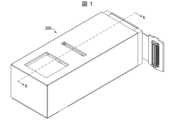
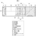
以下、本発明の一実施形態について、詳細に説明する。図1は実施形態1に係るカメラモジュール300の斜視図である。図2は図1に示すA-A矢視断面図であり、カメラモジュール300の中央部を光軸方向に切断した断面図に相当する。[Embodiment 1]
Hereinafter, one embodiment of the present invention will be described in detail. FIG. 1 is a perspective view of a
カメラモジュール300は、光学系304と、この光学系304を経由した物体光を集光する結像面311を有し、物体光を光電変換する撮像部306とを備える。 The
光学系304は、2枚以上のレンズを含み全体として正のパワーを有して物体光を受け取る第1レンズ群G1、1枚以上のレンズを含み全体として負のパワーを有して物体光を集光するために第1レンズ群G1の後段に配置される第2レンズ群G2、及び、第2レンズ群G2を第1光軸302に沿った方向に動かすレンズ駆動装置305を有する。 The
カメラモジュール300は、第1レンズ群G1の外周を保持する第1レンズバレル307と、第2レンズ群G2の外周を保持する第2レンズバレル308とをさらに備える。レンズ駆動装置305は、第2レンズバレル308の外周を保持する。 The
レンズ駆動装置305の第1光軸302に垂直な方向の寸法は、第1レンズバレル307の第1光軸302に垂直な方向の寸法よりも小さい。 The dimension of the
第1レンズバレル307は、第1レンズ群G1の外周を囲むように形成されたレンズ保持部312と、レンズ駆動装置305を内包するためにレンズ保持部312から第1光軸302に沿って延伸する駆動装置内包部313とを有する。 The
そして、カメラモジュール300は、光学系304の第1レンズ群G1よりも前段に配置される反射素子303をさらに備える。反射素子303は、第1光軸302に沿って放出される物体光を第1光軸302に沿って光学系304に導く。光学系304は、第1光軸302に沿って物体光を結像面311に集光する。 The
物体光を発する近距離物体へのフォーカシングにおいて第1光軸302に沿った方向における第1レンズ群G1と撮像部306との間の距離が変化しないように、第1レンズ群G1と撮像部306とは筐体BSに固定されている。 The first lens group G1 and the
実施形態1に係るカメラモジュール300は、図2に示すように、最も被写体側に配置され、被写体からの第1光軸302に沿った光を第1光軸302に沿って導く反射素子303と、この反射素子303よりも後段に配置される光学系304と、光学系304を経由した光の光電変換を行う撮像部306と、を備える構成となっている。 As shown in FIG. 2, the
光学系304は、最も反射素子303の近傍に位置する第1レンズ群G1と、第1レンズ群G1よりも後段に配置される第2レンズ群G2と、この第2レンズ群G2を第1光軸302に略一致する方向に動かすレンズ駆動装置305とを含む。 The
また、カメラモジュール300は、光学系304に内包される開口絞りStと、撮像部306の前方に配置される赤外線カットフィルタIRと、上記の全構成部品を直接的あるいは間接的に支持する筐体BSとをさらに備える。 The
反射素子303は、被写体から第1光軸302に沿って進む光線を折り曲げて第1光軸302に沿って導き、光学系304へ伝達する。反射素子303が光線を折り曲げる角度、すなわち第1光軸302と第1光軸302との間の角度は、90度が好適であるが、適宜変更することが出来、90度に限定されるものではない。 The
また反射素子303は、プリズム、反射板(鏡)等の種々の反射素材を適宜使用することができるが、加工精度から、プリズムを用いることが好ましい。 Further, as the
更に反射素子303は、カメラモジュール300の筐体BSによって支持されるが、反射素子303と筐体BSとの間に駆動機構を設けることで、後述の通り、光学式の手振れ補正機能を実現することが出来る。 Furthermore, the
光学系304は、反射素子303によって第1光軸302に沿って導かれた光線を、撮像部306の結像面311に集光させて結像させる。 The
光学系304は、第1レンズ群G1と、第2レンズ群G2と、開口絞りStと、を備え、筐体BSによって支持されるが、光学系304と筐体BSとの間に駆動機構を設けることで、後述の通り、光学式の手振れ補正機能を実現することが出来る。 The
レンズ駆動装置305は、第2光軸G2に略一致する方向に、第2レンズ群G2を駆動させることで、フォーカシングを行う。 The
図3は、図2に示すレンズ駆動装置305を光軸を含む平面で切断した断面図である。 FIG. 3 is a cross-sectional view of the
レンズ駆動装置305は、第2レンズバレル308の外周を保持する可動部309と、可動部309の外周側に配置されて、第2レンズバレル308を駆動する時に位置が変動しない固定部310とを備える。上記固定部310に対して可動部309を第1光軸302に沿って変位させることによって、第2レンズ群G2の第1光軸302方向の位置を調整することが出来る。 The
レンズ駆動装置305は、ステッピングモータを用いる装置、圧電素子を用いる装置、およびVCMを用いる装置等、様々な装置が知られており、いずれかに限定する必要は無い。しかしながら、サイズや性能、価格の面からVCMを用いるレンズ駆動装置305が望ましい。 Various types of
光学系304は、反射素子303によって第1光軸302に沿って導かれた光線を、撮像部306に集光させて結像させる。 The
撮像部306は、光電変換により、光学系304によって結像面311に集光した光線を電気信号に変換する、センサデバイスである。電気信号はソフトウェア処理を経て、最終的に画像へと出力される。 The
撮像部306は、筐体BSとの間に駆動機構を設けることで、後述の通り、光学式の手振れ補正機能を実現することが出来る。 By providing a drive mechanism between the
赤外線カットフィルタIRは、撮像部306に入射する光から、赤外線光を遮断する役割を有する。 The infrared cut filter IR has a role of blocking infrared light from light entering the
また、撮像部306に直接異物(ゴミ)が付着すると、集光が遮られ、画像が大きく劣化するため、赤外線カットフィルタIRを撮像部306よりも前方に設けることで、赤外線カットフィルタIRは撮像部306に異物が直接付着するリスクを低減する役割も有する。 In addition, if foreign matter (dust) directly adheres to the
なお、本実施形態に係るカメラモジュール300は、反射素子303を任意の2つの軸を回転軸として回動させることにより、光学式の手振れ補正を実現する構成にすることが出来る。 Note that the
上記の構成は、手振れの状態を検出するためのブレ検出手段と、ブレ検出手段から出力された信号に基づいて反射素子303の駆動部を制御するコントローラーと、反射素子303を回動させるための駆動部と、反射素子303を保持して駆動部の動きを伝えて反射素子303を動かす保持部材と、を含む。 The above configuration includes a shake detection means for detecting the state of camera shake, a controller for controlling the drive section of the
あるいは、本実施形態に係るカメラモジュール300は、光学系304を任意の2つの軸に平行に移動させることによっても、光学式の手振れ補正を実現する構成にすることが出来る。 Alternatively, the
上記の構成は、手振れの状態を検出するためのブレ検出手段と、ブレ検出手段から出力された信号に基づいて光学系304の駆動部を制御するコントローラーと、光学系304を移動させるための駆動部と、光学系304を保持して駆動部の動きを伝えて光学系304を動かす保持部材と、を含む。 The above configuration includes a shake detection means for detecting the state of camera shake, a controller for controlling the driving section of the
更にあるいは、本実施形態に係るカメラモジュールは、撮像部306を任意の2つの軸に平行に移動させることによっても、光学式の手振れ補正を実現する構成にすることが出来る。 Furthermore, the camera module according to this embodiment can also be configured to realize optical image stabilization by moving the
上記の構成は、手振れの状態を検出するためのブレ検出手段と、ブレ検出手段から出力された信号に基づいて撮像部306の駆動部を制御するコントローラーと、撮像部306を移動させるための駆動部と、撮像部306を保持して駆動部の動きを伝えて撮像部306を動かす保持部材と、を含む。 The above configuration includes a shake detection means for detecting the state of camera shake, a controller that controls the drive section of the
いずれの構成も、構成部品の2軸の駆動により光学式の手振れ補正を実現するものであることから、例えば、反射素子303の回転軸を1軸、光学系304の移動軸を別の1軸というように、別の部品の駆動方向を1軸ずつ組み合わせることでも、光学式の手振れ補正を実現することが出来る。 In both configurations, optical image stabilization is realized by driving the component parts along two axes. Optical image stabilization can also be achieved by combining the driving directions of different components one axis at a time.
これらの光学式の手振れ補正を実現する構成については、一般的に知られている為、詳細な説明および図示は省略する。 The configurations for implementing these optical camera shake corrections are generally known, and therefore detailed descriptions and illustrations will be omitted.
〔実施形態2〕
本発明の他の実施形態について、以下に説明する。なお、説明の便宜上、上記実施形態にて説明した部材と同じ機能を有する部材については、同じ符号を付記し、その説明を繰り返さない。[Embodiment 2]
Other embodiments of the invention will be described below. For convenience of explanation, members having the same functions as the members described in the above embodiment are given the same reference numerals, and the description thereof will not be repeated.
図4は実施形態2に係るカメラモジュールに設けられた光学系304の構成図である。図5は図4に示すB-B矢視断面斜視図であり、光学系304の中央部を光軸方向に切断した断面斜視図に相当する。 FIG. 4 is a configuration diagram of an
ところで、一般的な全群繰り出し方式においては、レンズ駆動装置の光軸に交差する方向の寸法を、全てのレンズの最大径に合わせた形状にする必要が有るのと、レンズ全群を駆動するための安定した駆動力を得るため、レンズ駆動装置の寸法を大きくする必要があり、カメラモジュールのサイズを決めるうえで、レンズ駆動装置の仕様は非常に重要になる。 By the way, in the general all-group extension method, it is necessary to shape the dimension of the lens drive device in the direction intersecting the optical axis to match the maximum diameter of all the lenses, and to drive all the lens groups. In order to obtain stable driving force for this purpose, it is necessary to increase the dimensions of the lens drive device, and the specifications of the lens drive device are extremely important when determining the size of the camera module.
また、いわゆる望遠レンズのような焦点距離の大きいレンズでは、画角が小さくなる為、撮像物側のレンズの光学有効径は、撮像素子側に位置するレンズの光学有効径に対して大きくなる。つまり一般的に、第1レンズ群G1の径は、撮像素子近く位置する第2レンズ群G2の径よりも大きい。 Furthermore, in the case of a lens with a large focal length such as a so-called telephoto lens, the angle of view becomes small, so the effective optical diameter of the lens on the side of the object to be imaged is larger than the effective diameter of the lens on the side of the image sensor. In other words, the diameter of the first lens group G1 is generally larger than the diameter of the second lens group G2 located near the image sensor.
本実施形態に係る構成によれば、レンズ駆動装置305が保持するレンズは第2レンズ群G2のみであるため、一般的な全群繰り出し方式に比べてレンズ駆動装置305を小型化することが可能となる。 According to the configuration according to this embodiment, since the lens that the
このため、本実施形態に係るレンズ駆動装置305は、レンズ駆動装置305の固定部310の第1光軸302に対して垂直方向の寸法は、第1レンズバレル307の第1光軸302に対して垂直方向の寸法よりも小さい特徴を有する。言い換えれば、本実施形態に係るカメラモジュールの寸法は、レンズ駆動装置305の大きさに影響されない。 Therefore, in the
その応用の構成として、例えば、第1レンズバレル307内にレンズ駆動装置305を内包することが出来る。具体的には、第1レンズバレル307の駆動装置内包部313にレンズ駆動装置305を内包することが出来る。 As a configuration for its application, for example, the
上記構成によれば、光学系304を一体の光学ユニットとすることが出来るため、光学系304のみでの生産と性能評価を行うことが簡易になるなど、生産面での利点が有る。また別の応用の構成として、第1レンズバレル307とレンズ駆動装置305を、それぞれ個々の部品として別個に組立を行うことでもまた、生産面での利点を出すことが出来る。 According to the above configuration, since the
例えば、まず筐体BSに対して、撮像部306と、第2レンズ群G2を内包するレンズ駆動装置305との組立を行い、その後に、筐体BSに対して第1レンズ群G1を内包する第1レンズバレル307の組立を行うとする。 For example, first, the
この際、撮像部306を用いて撮像情報を出力することにより、第1レンズバレル307の組立において、最も撮像の品質が良い組立位置を調整しながら、光学系304の第1レンズバレル307の組立を行うことが出来る。 At this time, by outputting imaging information using the
さらに、レンズ駆動装置305と筐体BSとを一体部品として用いることも可能であり、この場合、レンズ駆動装置305と筐体BSとの一体部品に対して、第2レンズ群G2を内包する第2レンズバレル308を組み付ける。上記構成によれば、レンズ駆動部の簡略化と、組立部品の低減を狙うことが出来る。 Furthermore, it is also possible to use the
当然ながら、逆に、まず筐体BSに対して撮像部306と、第1レンズ群G1を内包する第1レンズバレル307の組立を行い、その後に、筐体BSに対して第2レンズ群G2を内包するレンズ駆動装置305の組立位置の調整を行いながら、光学系304の組立を行うことも、可能である。 Of course, conversely, first the
〔実施形態3〕
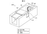
図6は実施形態3に係るカメラモジュールにおける、筐体BSに対して第1レンズバレル307を組付けた状態の斜視図である。[Embodiment 3]
FIG. 6 is a perspective view of the camera module according to the third embodiment, in which the
本発明の態様3に係るカメラモジュール300Aは、図6に示すように、第1レンズバレル307が突起構造314を有し、且つ、筐体BSが突起構造314を受けるための誘い込み構造315を有し、第1レンズバレル307の第1光軸302方向における撮像部306に対する位置が、突起構造314および誘い込み構造315によって固定されることを特徴とする。 In a
第1レンズバレル307は、底面と、底面の両端から突出する一対の側面と、一対の側面を繋ぐ天面とを備える。そして、一対の突起構造314が、一対の側面から外側に向かって突出する。 The
筐体BSは、底面と、底面の両端から突出する一対の側面とを備える。一対の側面は、一対の突起構造314とそれぞれ嵌合するように切り欠かれた一対の誘い込み構造315を有する。 The housing BS includes a bottom surface and a pair of side surfaces protruding from both ends of the bottom surface. The pair of side surfaces have a pair of
なお突起構造314は筐体BSに設けても良く、その場合、第1レンズバレル307に誘い込み構造315を設ける。 Note that the
上記の構成によれば、第1レンズ群G1の第1光軸302方向の位置調整を容易に行うことができる。 According to the above configuration, the position of the first lens group G1 in the first
(比較例)
図7は比較例に係るカメラモジュール100の斜視図である。カメラモジュール100は、特許文献1に示されたストレート型カメラモジュールである。カメラモジュール100は、撮像光学系である光学部1、光学部1を駆動するレンズ駆動装置2、光学部1を経由した光の光電変換を行う撮像部3とから構成される。光学部1は、レンズ駆動装置2の内部に保持されている。撮像部3は、センサ部4と、センサ部4が実装される基板5とから構成される。カメラモジュール100は、基板5上に、センサ部4、レンズ駆動装置2が、この順に光軸方向に積層された構成である。以下の説明では、便宜上、光学部1側を上方、撮像部3側を下方とする。(Comparative example)
FIG. 7 is a perspective view of a
図8は図7に示すC-C矢視断面図である。まず、図8に基づき、カメラモジュール100の全体構造について説明する。図9は、カメラモジュール100の中央部を光軸方向に切断した断面図である。 FIG. 8 is a sectional view taken along the line CC shown in FIG. First, the overall structure of the
光学部1は、被写体像を形成する撮像光学系であり、外部の光を撮像部3のセンサ部4へ導く。光学部1は、複数(図8では3枚)の撮像レンズ6と、撮像レンズ6を保持するレンズバレル7とから構成される。レンズバレル7は、レンズ駆動装置2に固定されている。撮像レンズ6の光軸は、レンズバレル7の軸心と一致している。 The
カメラモジュール100には、VCM(ボイスコイルモータ)タイプのレンズ駆動装置2が搭載されている。レンズ駆動装置2は、電磁力によって、光学部1を光軸方向に駆動する。すなわち、レンズ駆動装置2は、無限遠端からマクロ端の間で、撮像レンズ6を上下動させる。これにより、カメラモジュール100が、オートフォーカス機能を発揮する。このような撮像レンズ6一式を保持したレンズバレル7を繰り出す方式は全群操り出し方式と呼ばれる。 The
レンズ駆動装置2は、撮像レンズ6の駆動時に、光軸方向に移動して光学部1(撮像レンズ6)を光軸方向に移動させる可動部と、撮像レンズ6の駆動時に位置が変動しない固定部とを備えている。可動部は、固定部の内部に収容されている。可動部は、レンズホルダ8およびコイル10から構成されており、固定部は、ヨーク11、永久磁石12、カバー14、およびベース15から構成されている。 The
レンズホルダ8の外周端部(フランジ部)には、コイル10が固定されている。コイル10は、レンズホルダ8の外周端部(底部)から、光入射側(後述の開口13側)に延設されている。 A
ベース15は、レンズ駆動装置2の底部を構成しており、ベース15の裏面にセンサ部4が設けられる。ベース15の中央部には、光路を確保するために開口16が形成されている。 The
ヨーク11は、筒状の部材であり、レンズ駆動装置2の側面部を構成している。ヨーク11は、内部に可動部を収容する。ヨーク11はベース15上に固定されている。ヨーク11の上方に、カバー14が設けられている。カバー14は、レンズ駆動装置2の上部(天面)を構成している。 The
ヨーク11の内側面には、コイル10と対向するように、永久磁石12からなる磁気回路が配置されている。 A magnetic circuit including a
レンズ駆動装置2は、コイル10と永久磁石12とにより発生させた電磁力により、撮像レンズ6を光軸方向に駆動する。具体的には、本実施形態では、永久磁石12によって形成される磁場中のコイル10に電流を流すことで発生する力によって、撮像レンズ6(レンズホルダ8)を光軸方向に駆動することが可能となる。 The
また、レンズ駆動装置2では、レンズホルダ8の上下面(天面および底面)には、板ばね9a・bが設けられている。板ばね9a・9bは、レンズホルダ8を、光軸方向に押圧する。つまり、板ばね9a・9bは、弾性力により、補助的にレンズホルダ8を光軸方向に可動に支持している。板ばね9a・9bは、渦巻状のパターンを有している。板ばね9a・9bは、一端が可動部に、他端が固定部に固定されていればよい。 Further, in the
図8のように、カメラモジュール100の組立状態では、レンズホルダ8の底面に形成された突起19が、ベース15に当接しつつ、板ばね9a・9bの弾性力により、レンズホルダ8は下方向に与圧がかけられている。 As shown in FIG. 8, when the
前述した従来のストレート型カメラモジュール100の厚みは、レンズ先端から撮像素子面までの光学長、撮像素子、基板などの厚みと、フォーカシングのためのレンズの全群操り出し量から規定される。この光学長と全群繰り出し量とを加えた値を光学全長と称する。 The thickness of the conventional straight
上記の内、一般的に光学長は焦点距離(画角)に比例し、レンズの全群操り出し量は以下式の通り焦点距離の二乗に凡そ比例する。
1/a+1/b=1/f⇒b=af/(a-f)
d=b-f=f2/(a-f)≒f2/a(但しf≪a)
ここで、aはレンズの主点から被写体までの距離、bはレンズの主点から結像面までの距離、fは実焦点距離、dは無限遠からa位置へのフォーカシングのために必要なレンズの全群繰り出し量である。Among the above, the optical length is generally proportional to the focal length (angle of view), and the amount of movement of the entire lens group is approximately proportional to the square of the focal length, as shown in the following equation.
1/a+1/b=1/f⇒b=af/(a-f)
d=b−f=f2 /(a−f)≒f2 /a (however, f≪a)
Here, a is the distance from the principal point of the lens to the subject, b is the distance from the principal point of the lens to the imaging plane, f is the actual focal length, and d is the lens required for focusing from infinity to position a. This is the total group extension amount.
例えば従来のストレート構造のカメラモジュール100は、広角レンズ採用が主で、35mm換算焦点距離25mm程度を採用する。その光学長と全群操り出し量であるが、1/2型センサの場合、光学長は5mm、10cmフォーカシングの全群操り出し量は前記の数式によれば約0.2mmとなる。 For example, the conventional straight-structured
ところで近年は複数のカメラモジュールを備えた多眼レンズ搭載または多眼カメラ搭載と呼ばれるスマートフォンなどの電子機器が登場している。これは広角カメラに加え超広角や望遠レンズを備えたカメラモジュールを搭載し、デジタル補正を組み合わせ使用者にズームカメラのような使い勝手を提供するものである。 Incidentally, in recent years, electronic devices such as smartphones equipped with multi-lens lenses or multi-cameras equipped with a plurality of camera modules have appeared. In addition to a wide-angle camera, this camera module is equipped with an ultra-wide-angle and telephoto lens, and is combined with digital correction to provide users with the usability of a zoom camera.
2眼カメラでズーム比率4倍とする場合、広角側が35mm換算焦点距離25mでは、望遠側35mm換算焦点距離100mmの光学系を望遠側は採用する。その光学長と全群操り出し量であるが1/2型センサの場合、光学長は19mm、全群操り出し量は約4.2mmとなり、同サイズのセンサを採用したカメラの約4倍以上のモジュール厚みとなる。そこで望遠側はセンササイズを小さくすることが多いが1/4型センサの場合でも、光学長は10mm、全群操り出し量は約1.2mmと2倍以上の厚みとなる。 When using a twin-lens camera with a zoom ratio of 4x, when the wide-angle side has a 35 mm equivalent focal length of 25 m, the telephoto side uses an optical system with a 35 mm equivalent focal length of 100 mm. Regarding the optical length and total group extension, in the case of a 1/2-inch sensor, the optical length is 19 mm and the total group extension is about 4.2 mm, which is about 4 times more than a camera using the same size sensor. module thickness. Therefore, the sensor size is often made smaller on the telephoto side, but even in the case of a 1/4-inch sensor, the optical length is 10 mm and the total group extension is about 1.2 mm, which is more than twice the thickness.
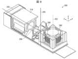
そこでこの望遠側のカメラモジュールの厚みを小さくするために、図9に示すような、折り曲げ型光学系のカメラモジュール構造が提案されている。図9は他の比較例に係るカメラモジュール200の斜視図である。 Therefore, in order to reduce the thickness of the camera module on the telephoto side, a camera module structure of a folding optical system as shown in FIG. 9 has been proposed. FIG. 9 is a perspective view of a
この折り曲げ型のカメラモジュール200は、図9に示すように、プリズムやミラーなどの反射素子208を備えており、光軸方向をスマートフォン裏面に対して垂直な方向205からスマートフォン裏面に対して平行な方向206に傾けることが出来る。 As shown in FIG. 9, this
しかしながら、図9に示すカメラモジュール200において、全群操り出し方式と折り曲げ光学系とを組み合わせた場合は、レンズバレル214と反射素子208との間に、レンズ駆動装置によるレンズバレル214の全群操り出し量以上の隙間距離が必要となる。この隙間距離に応じて、レンズの画角分だけ光線が広がる。光線が広がれば反射素子208も大きくする必要が有り、カメラモジュール200の厚みやフットプリントも大きくなる。 However, in the
従って、全群操り出し量が長いレンズ駆動装置を得ようとすればカメラモジュール200は大型化し、小型化・薄型化は困難となる。 Therefore, if an attempt is made to obtain a lens driving device with a long total group extension amount, the
レンズ駆動装置の大型化は消費電力の増加につながり、カメラモジュール200を搭載する電子機器の電池持続時間や端末の小型化や、果ては電池コストに影響を与える。 Increasing the size of the lens drive device leads to an increase in power consumption, which affects the battery life of electronic devices equipped with the
また、ストレート型、折り曲げ型を問わずVCM方式のレンズ駆動装置は、レンズ駆動装置の可動部を、バネで支持する構造が一般的である。このため、焦点距離、全群操り出し量が大きくなると、そのバネの反発力も大きくなる。その結果、多大な推力が必要になること、および、バネの変形量が大きくなるためにバネに多大な歪を与えるなどの問題が生じる。バネの歪は光軸に対するレンズ駆動装置の動作軸の傾きを誘発し、傾いた光学系によれば撮像画質の低下を引き起こす。 In addition, VCM type lens driving devices, regardless of whether they are straight type or bent type, generally have a structure in which the movable part of the lens driving device is supported by a spring. For this reason, as the focal length and total group movement amount increase, the repulsive force of the spring also increases. As a result, a large amount of thrust is required, and the amount of deformation of the spring becomes large, causing problems such as giving a large amount of strain to the spring. The distortion of the spring induces a tilt of the operating axis of the lens driving device with respect to the optical axis, and a tilted optical system causes a reduction in image quality.
これに対して、実施形態1~5に係るカメラモジュール300の光学系304は、2枚以上のレンズを含み全体として正のパワーを有して物体光を受け取る第1レンズ群G1、及び、1枚以上のレンズを含み全体として負のパワーを有して物体光を撮像部に集光するために第1レンズ群G1の後段に配置される第2レンズ群G2が、-6.0<f/f2<-2.0 条件式(1)、ih/f<0.4 条件式(2)、0.7<TTL/f<1.0 条件式(3)、1.6<Fno<7.0 条件式(4)、De2<De1 条件式(5)、を満足する。 In contrast, the
このため、物体光を発する近距離物体へのフォーカシングが、第2レンズ群G2をその第1光軸302に沿った方向に動かすことにより可能になる。従って、全群繰り出し方式を採用する必要が無くなり、第2レンズ群G2のみを繰り出すことにより上記フォーカシングが可能になる。この結果、光学系304、カメラモジュール300の小型化・薄型化を実現することができる。 Therefore, focusing on a short-distance object that emits object light becomes possible by moving the second lens group G2 in the direction along its first
〔まとめ〕
本発明の態様1に係るカメラモジュール300・300Aは、2枚以上のレンズを含み全体として正のパワーを有して物体光を受け取る第1レンズ群G1を保持する第1レンズバレル307と、1枚以上のレンズを含み全体として負のパワーを有して前記物体光を集光するために前記第1レンズ群G1に対して前記物体光の進行方向側に配置される第2レンズ群G2を保持する第2レンズバレル308と、前記第2レンズ群G2をその第1光軸302に沿った方向に動かすために前記第2レンズバレル308の外周を保持するレンズ駆動装置305とを備え、前記レンズ駆動装置305の前記第1光軸302に交差する方向の寸法が、前記第1レンズバレル307の前記第1光軸302に交差する方向の寸法よりも小さい。〔summary〕
上記の構成によれば、レンズ駆動装置の第1光軸に交差する方向の寸法を小さくすることができる。このため、一般的な全群繰り出し方式に比べてカメラモジュールを小型化することが可能となる。 According to the above configuration, the dimension of the lens driving device in the direction intersecting the first optical axis can be reduced. Therefore, it is possible to downsize the camera module compared to the general all-group extension method.
本発明の態様2に係るカメラモジュール300・300Aは、上記態様1において、前記レンズ駆動装置305が、前記第1レンズバレル307に内包されていることが好ましい。 In the
上記の構成によれば、光学系を一体の光学ユニットとすることが出来るため、光学系のみでの生産と性能評価を行うことが簡易になるなど、生産面での利点が生じる。 According to the above configuration, since the optical system can be formed into an integrated optical unit, there are advantages in terms of production, such as making it easier to produce and evaluate the performance of the optical system alone.
本発明の態様3に係るカメラモジュール300・300Aは、上記態様1において、前記物体光が集光される撮像部306をさらに備え、前記第1レンズバレル307は、前記撮像部306に対する位置が固定されていることが好ましい。
上記の構成によれば、第1レンズ群の第1光軸方向の位置調整を容易に行うことができる。 According to the above configuration, the position of the first lens group in the first optical axis direction can be easily adjusted.
本発明の態様4に係るカメラモジュール300Aは、上記態様1において、前記第1レンズバレル307を収容する筐体BSをさらに備え、前記第1レンズバレル307と前記筐体BSとの一方に、前記第1レンズバレル307の径方向に沿って突出する突起構造314が形成され、前記第1レンズバレル307と前記筐体BSとの他方に、前記突起構造314に対する誘い込み構造315が形成されることが好ましい。 A
上記の構成によれば、第1レンズバレルの撮像部に対する位置を容易に固定することができる。 According to the above configuration, the position of the first lens barrel relative to the imaging section can be easily fixed.
本発明の態様5に係るカメラモジュール300・300Aは、上記態様1において、前記レンズ駆動装置305が、前記第2レンズ群G2をその第1光軸302に沿った方向に動かすために移動する可動部309と、前記第2レンズ群G2を動かす時に位置が変動しない固定部310とを有し、前記固定部310の前記第1光軸302に交差する方向の寸法が、前記第1レンズバレル307の前記第1光軸302に交差する方向の寸法よりも小さいことが好ましい。
上記の構成によれば、レンズ駆動装置の固定部の第1光軸に交差する方向の寸法を小さくすることができる。 According to the above configuration, the dimension of the fixed portion of the lens driving device in the direction intersecting the first optical axis can be reduced.
本発明の態様6に係るカメラモジュール300・300Aは、上記態様1において、前記第1レンズ群G1に対して前記物体光の進行方向の反対側に配置される反射素子303をさらに備え、前記反射素子303は、前記第1光軸302に交差する第2光軸301に沿って放出される前記物体光を前記第1光軸302に沿って導き、前記第1レンズ群G1及び前記第2レンズ群G2は、前記第1光軸302に沿って前記物体光を集光することが好ましい。
上記の構成によれば、折り曲げ型光学系のカメラモジュール構造とすることが出来、光軸方向をスマートフォン裏面に対して垂直な方向からスマートフォン裏面に対して平行な方向に傾けることが出来、本発明において好適である。 According to the above configuration, it is possible to have a camera module structure with a folding optical system, and the optical axis direction can be tilted from a direction perpendicular to the back surface of the smartphone to a direction parallel to the back surface of the smartphone, and the present invention It is suitable for
本発明は上述した各実施形態に限定されるものではなく、請求項に示した範囲で種々の変更が可能であり、異なる実施形態にそれぞれ開示された技術的手段を適宜組み合わせて得られる実施形態についても本発明の技術的範囲に含まれる。さらに、各実施形態にそれぞれ開示された技術的手段を組み合わせることにより、新しい技術的特徴を形成することができる。 The present invention is not limited to the embodiments described above, and various modifications can be made within the scope of the claims, and embodiments obtained by appropriately combining technical means disclosed in different embodiments. are also included within the technical scope of the present invention. Furthermore, new technical features can be formed by combining the technical means disclosed in each embodiment.
300 カメラモジュール
301 第2光軸
302 第1光軸
303 反射素子
304 光学系
305 レンズ駆動装置
306 撮像部
307 第1レンズバレル
308 第2レンズバレル
311 結像面
312 レンズ保持部
313 駆動装置内包部
314 突起構造
315 誘い込み構造
G1 第1レンズ群
G2 第2レンズ群300
Claims (6)
Translated fromJapanese1枚以上のレンズを含み全体として負のパワーを有して前記物体光を集光するために前記第1レンズ群に対して前記物体光の進行方向側に配置される第2レンズ群を保持する第2レンズバレルと、
前記第2レンズ群をその第1光軸に沿った方向に動かすために前記第2レンズバレルの外周を保持するレンズ駆動装置とを備え、
前記レンズ駆動装置の前記第1光軸に交差する方向の寸法が、前記第1レンズバレルの前記第1光軸に交差する方向の寸法よりも小さいことを特徴とするカメラモジュール。a first lens barrel that holds a first lens group that includes two or more lenses and has positive power as a whole and receives object light;
A second lens group including one or more lenses having negative power as a whole and disposed on the traveling direction side of the object light with respect to the first lens group in order to condense the object light. a second lens barrel;
a lens driving device that holds the outer periphery of the second lens barrel in order to move the second lens group in a direction along the first optical axis;
A camera module characterized in that a dimension of the lens driving device in a direction intersecting the first optical axis is smaller than a dimension of the first lens barrel in a direction intersecting the first optical axis.
前記第1レンズバレルは、前記撮像部に対する位置が固定されている請求項1に記載のカメラモジュール。further comprising an imaging unit on which the object light is focused,
The camera module according to claim 1, wherein the first lens barrel has a fixed position relative to the imaging section.
前記第1レンズバレルと前記筐体との一方に、前記第1レンズバレルの径方向に沿って突出する突起構造が形成され、
前記第1レンズバレルと前記筐体との他方に、前記突起構造に対する誘い込み構造が形成される請求項1に記載のカメラモジュール。further comprising a housing that accommodates the first lens barrel,
A protrusion structure that protrudes along the radial direction of the first lens barrel is formed on one of the first lens barrel and the housing,
The camera module according to claim 1, wherein a guide structure for the protrusion structure is formed on the other of the first lens barrel and the housing.
前記固定部の前記第1光軸に交差する方向の寸法が、前記第1レンズバレルの前記第1光軸に交差する方向の寸法よりも小さい請求項1に記載のカメラモジュール。The lens driving device has a movable part that moves to move the second lens group in a direction along its first optical axis, and a fixed part whose position does not change when moving the second lens group,
The camera module according to claim 1, wherein a dimension of the fixing portion in a direction intersecting the first optical axis is smaller than a dimension of the first lens barrel in a direction intersecting the first optical axis.
前記反射素子は、前記第1光軸に交差する第2光軸に沿って放出される前記物体光を前記第1光軸に沿って導き、
前記第1レンズ群及び前記第2レンズ群は、前記第1光軸に沿って前記物体光を集光する請求項1に記載のカメラモジュール。further comprising a reflective element disposed on the opposite side of the traveling direction of the object light with respect to the first lens group,
The reflective element guides the object light emitted along a second optical axis intersecting the first optical axis along the first optical axis,
The camera module according to claim 1, wherein the first lens group and the second lens group condense the object light along the first optical axis.
Priority Applications (3)
| Application Number | Priority Date | Filing Date | Title |
|---|---|---|---|
| JP2022045517AJP2023139801A (en) | 2022-03-22 | 2022-03-22 | Camera module |
| US17/971,625US20230324646A1 (en) | 2022-03-22 | 2022-10-23 | Camera module |
| CN202211328632.1ACN116819855A (en) | 2022-03-22 | 2022-10-27 | camera module |
Applications Claiming Priority (1)
| Application Number | Priority Date | Filing Date | Title |
|---|---|---|---|
| JP2022045517AJP2023139801A (en) | 2022-03-22 | 2022-03-22 | Camera module |
Publications (1)
| Publication Number | Publication Date |
|---|---|
| JP2023139801Atrue JP2023139801A (en) | 2023-10-04 |
Family
ID=88126277
Family Applications (1)
| Application Number | Title | Priority Date | Filing Date |
|---|---|---|---|
| JP2022045517APendingJP2023139801A (en) | 2022-03-22 | 2022-03-22 | Camera module |
Country Status (3)
| Country | Link |
|---|---|
| US (1) | US20230324646A1 (en) |
| JP (1) | JP2023139801A (en) |
| CN (1) | CN116819855A (en) |
Citations (3)
| Publication number | Priority date | Publication date | Assignee | Title |
|---|---|---|---|---|
| JP2010066713A (en)* | 2008-09-12 | 2010-03-25 | Fujinon Corp | Lens apparatus |
| KR20210041947A (en)* | 2019-10-08 | 2021-04-16 | 엘지이노텍 주식회사 | Camera actuator and camera device comprising the same |
| KR20210117013A (en)* | 2020-03-18 | 2021-09-28 | 엘지이노텍 주식회사 | Optical system and camera module for comprising the same |
- 2022
- 2022-03-22JPJP2022045517Apatent/JP2023139801A/enactivePending
- 2022-10-23USUS17/971,625patent/US20230324646A1/enactivePending
- 2022-10-27CNCN202211328632.1Apatent/CN116819855A/enactivePending
Patent Citations (3)
| Publication number | Priority date | Publication date | Assignee | Title |
|---|---|---|---|---|
| JP2010066713A (en)* | 2008-09-12 | 2010-03-25 | Fujinon Corp | Lens apparatus |
| KR20210041947A (en)* | 2019-10-08 | 2021-04-16 | 엘지이노텍 주식회사 | Camera actuator and camera device comprising the same |
| KR20210117013A (en)* | 2020-03-18 | 2021-09-28 | 엘지이노텍 주식회사 | Optical system and camera module for comprising the same |
Also Published As
| Publication number | Publication date |
|---|---|
| CN116819855A (en) | 2023-09-29 |
| US20230324646A1 (en) | 2023-10-12 |
Similar Documents
| Publication | Publication Date | Title |
|---|---|---|
| US8837929B2 (en) | Imaging apparatus | |
| US9025945B2 (en) | Imaging apparatus | |
| US9635264B2 (en) | Imaging apparatus | |
| JP6960983B2 (en) | Imaging device with image stabilization function | |
| JP2013238848A (en) | Imaging apparatus | |
| KR20150091017A (en) | Imaging apparatus | |
| KR20150091022A (en) | Imaging apparatus | |
| KR20230061315A (en) | camera module | |
| WO2021213216A1 (en) | Periscopic camera module, multi-camera module and method for assembling camera module | |
| WO2021171030A1 (en) | A camera assembly | |
| JP5997993B2 (en) | Imaging device | |
| CN114114595B (en) | Lens module, camera module and terminal | |
| WO2018062219A1 (en) | Lens unit and camera module | |
| KR102527321B1 (en) | camera module | |
| KR102488750B1 (en) | camera module | |
| JP2023139801A (en) | Camera module | |
| JP7254864B2 (en) | Optical system and camera module | |
| US20240061220A1 (en) | Optical system and camera module | |
| JP2022552507A (en) | Camera actuator and camera device including the same | |
| CN220252271U (en) | Long-focus lens module and electronic equipment | |
| JP2023132712A (en) | Optical system and camera module | |
| KR20250102681A (en) | camera module | |
| CN116224538A (en) | Camera module | |
| JP2007047684A (en) | Lens driving device and mobil phone terminal with camera | |
| JP5895464B2 (en) | Lens barrel and imaging device |
Legal Events
| Date | Code | Title | Description |
|---|---|---|---|
| A625 | Written request for application examination (by other person) | Free format text:JAPANESE INTERMEDIATE CODE: A625 Effective date:20240919 | |
| A977 | Report on retrieval | Free format text:JAPANESE INTERMEDIATE CODE: A971007 Effective date:20250521 | |
| A131 | Notification of reasons for refusal | Free format text:JAPANESE INTERMEDIATE CODE: A131 Effective date:20250527 | |
| A521 | Request for written amendment filed | Free format text:JAPANESE INTERMEDIATE CODE: A523 Effective date:20250625 | |
| A131 | Notification of reasons for refusal | Free format text:JAPANESE INTERMEDIATE CODE: A131 Effective date:20250909 |