JP2023137311A - Gas detection device and gas detection method - Google Patents
Gas detection device and gas detection methodDownload PDFInfo
- Publication number
- JP2023137311A JP2023137311AJP2022043455AJP2022043455AJP2023137311AJP 2023137311 AJP2023137311 AJP 2023137311AJP 2022043455 AJP2022043455 AJP 2022043455AJP 2022043455 AJP2022043455 AJP 2022043455AJP 2023137311 AJP2023137311 AJP 2023137311A
- Authority
- JP
- Japan
- Prior art keywords
- gas
- light
- irradiation
- section
- irradiation position
- Prior art date
- Legal status (The legal status is an assumption and is not a legal conclusion. Google has not performed a legal analysis and makes no representation as to the accuracy of the status listed.)
- Granted
Links
Images


Classifications
- G—PHYSICS
- G01—MEASURING; TESTING
- G01N—INVESTIGATING OR ANALYSING MATERIALS BY DETERMINING THEIR CHEMICAL OR PHYSICAL PROPERTIES
- G01N21/00—Investigating or analysing materials by the use of optical means, i.e. using sub-millimetre waves, infrared, visible or ultraviolet light
- G01N21/17—Systems in which incident light is modified in accordance with the properties of the material investigated
- G01N21/25—Colour; Spectral properties, i.e. comparison of effect of material on the light at two or more different wavelengths or wavelength bands
- G01N21/31—Investigating relative effect of material at wavelengths characteristic of specific elements or molecules, e.g. atomic absorption spectrometry
- G01N21/35—Investigating relative effect of material at wavelengths characteristic of specific elements or molecules, e.g. atomic absorption spectrometry using infrared light
- G01N21/3504—Investigating relative effect of material at wavelengths characteristic of specific elements or molecules, e.g. atomic absorption spectrometry using infrared light for analysing gases, e.g. multi-gas analysis
- G—PHYSICS
- G01—MEASURING; TESTING
- G01N—INVESTIGATING OR ANALYSING MATERIALS BY DETERMINING THEIR CHEMICAL OR PHYSICAL PROPERTIES
- G01N21/00—Investigating or analysing materials by the use of optical means, i.e. using sub-millimetre waves, infrared, visible or ultraviolet light
- G01N21/17—Systems in which incident light is modified in accordance with the properties of the material investigated
- G01N2021/1793—Remote sensing
- G—PHYSICS
- G01—MEASURING; TESTING
- G01N—INVESTIGATING OR ANALYSING MATERIALS BY DETERMINING THEIR CHEMICAL OR PHYSICAL PROPERTIES
- G01N2201/00—Features of devices classified in G01N21/00
- G01N2201/06—Illumination; Optics
- G01N2201/061—Sources
- G01N2201/06113—Coherent sources; lasers
- G—PHYSICS
- G01—MEASURING; TESTING
- G01N—INVESTIGATING OR ANALYSING MATERIALS BY DETERMINING THEIR CHEMICAL OR PHYSICAL PROPERTIES
- G01N2201/00—Features of devices classified in G01N21/00
- G01N2201/06—Illumination; Optics
- G01N2201/063—Illuminating optical parts
- G01N2201/0636—Reflectors
Landscapes
- Physics & Mathematics (AREA)
- Spectroscopy & Molecular Physics (AREA)
- Health & Medical Sciences (AREA)
- Life Sciences & Earth Sciences (AREA)
- Chemical & Material Sciences (AREA)
- Analytical Chemistry (AREA)
- Biochemistry (AREA)
- General Health & Medical Sciences (AREA)
- General Physics & Mathematics (AREA)
- Immunology (AREA)
- Pathology (AREA)
- Investigating Or Analysing Materials By Optical Means (AREA)
Abstract
Translated fromJapaneseDescription
Translated fromJapanese本発明の実施形態は、ガス検出装置、およびガス検出方法に関する。 Embodiments of the present invention relate to a gas detection device and a gas detection method.
分子は、赤外線に対して固有の吸収スペクトルを有する。そのため、対象となる空間に赤外線を照射すれば、空間に放出されたガスの検出や、空間に放出されたガスの成分分析を行うことができる。
ところが、空間に放出されたガスの濃度(密度)には分布がある。そのため、空間に放出されたガスにおける赤外線の照射位置によっては、検出感度や分析精度が低下するおそれがある。
そこで、空間に放出されたガスを適切に検出することができる技術の開発が望まれていた。Molecules have a unique absorption spectrum for infrared radiation. Therefore, by irradiating the target space with infrared rays, gas released into the space can be detected and the components of the gas released into the space can be analyzed.
However, there is a distribution in the concentration (density) of the gas released into space. Therefore, depending on the irradiation position of the infrared rays in the gas released into space, detection sensitivity and analysis accuracy may be reduced.
Therefore, it has been desired to develop a technology that can appropriately detect gas released into space.
本発明が解決しようとする課題は、空間に放出されたガスを適切に検出することができるガス検出装置、およびガス検出方法を提供することである。 The problem to be solved by the present invention is to provide a gas detection device and a gas detection method that can appropriately detect gas released into space.
実施形態に係るガス検出装置は、空間に放出されたガスに、第1の波長を有する第1の光を照射可能な第1の照射部と、前記ガスに、前記第1の波長よりも短い第2の波長を有する第2の光を照射可能な第2の照射部と、前記ガスにおける前記第1の光の照射位置を制御可能な照射位置調整部と、前記ガスを透過した前記第1の光に基づいて、前記ガスの成分を分析可能なガス分析部と、前記ガスを透過した前記第2の光に基づいて、前記ガスの濃度分布を可視化可能なガス可視化部と、を備えている。前記照射位置調整部は、可視化された前記ガスの濃度分布に基づいて、前記ガスにおける前記第1の光の照射位置を制御する。 The gas detection device according to the embodiment includes: a first irradiation unit capable of irradiating first light having a first wavelength to gas released into space; a second irradiation unit that can irradiate a second light having a second wavelength; an irradiation position adjustment unit that can control the irradiation position of the first light in the gas; a gas analysis unit capable of analyzing the components of the gas based on the light; and a gas visualization unit capable of visualizing the concentration distribution of the gas based on the second light transmitted through the gas. There is. The irradiation position adjustment section controls the irradiation position of the first light on the gas based on the visualized concentration distribution of the gas.
以下、図面を参照しつつ、実施の形態について例示をする。なお、各図面中、同様の構成要素には同一の符号を付して詳細な説明は適宜省略する。
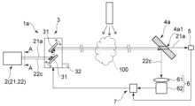
図1は、本実施の形態に係るガス検出装置1を例示するための模式図である。
なお、図1においては、繁雑となるのを避けるために、光21aと光22cを離隔させて描いている。
図2は、図1における光源2をA-A線方向から見た模式図である。
図1に示すように、ガス検出装置1は、光源2、照射位置調整部3、光分割部4、ガス分析部5、ガス可視化部6、およびコントローラ7を有する。Hereinafter, embodiments will be illustrated with reference to the drawings. Note that in each drawing, similar components are denoted by the same reference numerals, and detailed explanations are omitted as appropriate.
FIG. 1 is a schematic diagram illustrating a
Note that in FIG. 1, the
FIG. 2 is a schematic diagram of the
As shown in FIG. 1, the
図1および図2に示すように、光源2は、例えば、第1の照射部21、および第2の照射部22を有する。
第1の照射部21は、空間に放出されたガス100に、光21a(第1の光の一例に相当する)を照射する。光21aの波長は、例えば、0.7μm以上(第1の波長の一例に相当する)である。光21aは、例えば、赤外線や近赤外線などである。第1の照射部21は、例えば、化合物半導体を含む量子カスケードレーザ(QCL:Quantum Cascade Laser)などである。第1の照射部21を量子カスケードレーザとすれば、第1の照射部21の小型化が容易となる。As shown in FIGS. 1 and 2, the
The first irradiation unit 21 irradiates the
第2の照射部22は、空間に放出されたガス100に、光22c(第2の光の一例に相当する)を照射する。
第2の照射部22は、例えば、発光部22a、およびドットパターンを形成するフィルタ22bを有する。 発光部22aは、光22cを照射する。光22cの波長(第2の波長の一例に相当する)は、光21aの波長よりも短い。光22cの波長は、例えば、360nm以上、830nm以下である。光22cは、例えば、赤色光などの可視光である。発光部22aは、例えば、発光素子、放電ランプなどとすることができる。発光素子は、例えば、発光ダイオード、レーザダイオード、有機発光ダイオードなどである。この場合、発光部22aを発光素子とすれば、第2の照射部22の小型化が容易となる。また、第1の照射部21の光軸と、第2の照射部22の光軸との間の距離を短くすることができる。The second irradiation unit 22 irradiates the
The second irradiation section 22 includes, for example, a light emitting section 22a and a filter 22b that forms a dot pattern. The light emitting section 22a emits
発光部22aは、少なくとも1つ設けることができる。発光部22aを複数設ける場合には、第1の照射部21の光軸に沿った方向から見て、第1の照射部21を囲む様に複数の発光部22aを設けることができる。この場合、複数の発光部22aは、例えば、第1の照射部21の光軸を中心として点対称となる位置に設けることができる。 At least one light emitting section 22a can be provided. When providing a plurality of light emitting sections 22a, the plurality of light emitting sections 22a can be provided so as to surround the first irradiating section 21 when viewed from the direction along the optical axis of the first irradiating section 21. In this case, the plurality of light emitting parts 22a can be provided, for example, at positions that are point symmetrical about the optical axis of the first irradiation part 21.
ドットパターンを形成するフィルタ22bは、板状を呈し、発光部22aの光22cの照射側に設けられている。ドットパターンを形成するフィルタ22bは、厚み方向を貫通する孔22b1を有する。第1の照射部21から照射された光21aは、孔22b1を介して、ガス100に照射される。発光部22aから照射された光22cは、ドットパターンを形成するフィルタ22bを介して、ガス100に照射される。 The filter 22b forming the dot pattern has a plate shape and is provided on the light 22c irradiation side of the light emitting section 22a. The filter 22b forming the dot pattern has holes 22b1 penetrating in the thickness direction. The
ドットパターンを形成するフィルタ22bの面には、微細な凹凸が設けられている。ドットパターンを形成するフィルタ22bの面に微細な凹凸が設けられていれば、第2の照射部22から照射される光22cに明暗のムラを与えることができる。光22cに明暗のムラがあれば、後述するガス100の濃度分布の可視化を行った際に、コントラストを高めることができる。
この場合、凹凸の配置に一定の規則性が有ると、モアレと呼ばれる干渉縞が生ずるおそれがある。そのため、凹凸の配置は、ランダムであることが好ましい。例えば、ドットパターンを形成するフィルタ22bは、いわゆるランダムドットパターンを形成するフィルタとすることができる。Fine irregularities are provided on the surface of the filter 22b forming the dot pattern. If fine irregularities are provided on the surface of the filter 22b forming the dot pattern, unevenness in brightness can be imparted to the
In this case, if there is a certain regularity in the arrangement of the unevenness, interference fringes called moiré may occur. Therefore, it is preferable that the arrangement of the unevenness is random. For example, the filter 22b that forms a dot pattern can be a filter that forms a so-called random dot pattern.
ここで、複数の発光部22aから照射される光22cの中心軸は、第1の照射部21の光軸と必ずしも同軸である必要はない。例えば、第2の照射部22は、第1の照射部21と離隔させて別体に設けることもできる。 Here, the central axis of the
ただし、第1の照射部21の光軸が、第2の照射部22の光軸と同軸であれば、ガス100における光21aの照射位置の制御が容易となる。なお、光21aの照射位置の制御に関する詳細は後述する。 However, if the optical axis of the first irradiation section 21 is coaxial with the optical axis of the second irradiation section 22, the irradiation position of the
例えば、複数の発光部22aが、第1の照射部21の光軸を中心として点対称となる位置に設けられていれば、第1の照射部21の光軸が、第2の照射部22の光軸と同軸となる様にすることができる。 For example, if the plurality of light emitting units 22a are provided at positions that are point symmetrical about the optical axis of the first irradiating unit 21, the optical axis of the first irradiating unit 21 will be the same as that of the second irradiating unit 22. It can be made to be coaxial with the optical axis of.
また、光21aと光22cは、必ずしも同時に照射する必要はない。例えば、まず、光22cをガス100に照射して後述するガス100の濃度分布の可視化を行うことができる。次に、可視化されたガス100の濃度分布に基づいて、ガス100における光21aの照射位置を求めることができる。次に、求められた照射位置に向けて光21aを照射することができる。 Further, the
照射位置調整部3は、ガス100における光21a、22cの照射位置の制御を行う。 照射位置調整部3は、例えば、ミラー31、および駆動部32を有する。
ミラー31は、少なくとも1つ設けることができる。ミラー31は、揺動可能に設けられている。ミラー31は、入射した光21a、22cを反射させてガス100に入射させる。ミラー31からの反射光は、平行光であってもよいし、発散光であってもよい。ただし、光22cが平行光であれば、後述するガス100の濃度分布の可視化が容易となる。The irradiation
At least one
駆動部32は、ミラー31の角度を変化させることで、光21a、22の反射角、ひいてはガス100における光21a、22cの照射位置を変化させる。駆動部32は、例えば、サーボモータなどの制御モータを備えたものとすることができる。 By changing the angle of the
光分割部4にはガス100を透過した光21a、22が入射する。照射位置調整部3と光分割部4との間の距離には特に限定がない。例えば、ガス検出装置1は、離れた位置からガス100を検出する遠隔検出に用いることができる。ただし、ガス検出装置1の用途は遠隔検出に限定されるわけではない。照射位置調整部3と光分割部4との間の距離は、短くてもよい。 Light beams 21 a and 22 that have passed through the
光分割部4は、光21aと光22cを分割する。例えば、光分割部4は、ビームスプリッタとすることができる。例えば、図1に示すように、光分割部4は、光21aを透過し、光22cを反射する。図1に例示をした光分割部4は、例えば、ハーフミラーである。
また、光分割部4を揺動可能に設け、ミラー31の揺動位置(光21a、22cの反射位置)に応じて、光分割部4の位置を変化させてもよい。例えば、光分割部4にも駆動部32を設けることができる。The
Alternatively, the
ガス100と光分割部4を透過した光21aはガス分析部5に入射する。ガス分析部5は、ガス100を透過した光21aに基づいて、ガス100の成分を分析する。例えば、入射した光21aの波数を横軸に、透過率(吸光度)を縦軸にとることで得られる赤外吸収スペクトルは、分子に固有の形を有する。そのため、得られた赤外吸収スペクトルに基づいて、ガス100に含まれる分子、すなわちガス100の成分を分析することができる。 The light 21a transmitted through the
そのため、ガス分析部5は、赤外線や近赤外線を検出するセンサとすることができる。ガス分析部5は、例えば、水銀(Hg)・カドニウム(Cd)・テルル(Te)を用いた半導体センサであるMCTセンサとすることができる。ガス分析部5は、検出されたガス100の成分のデータをコントローラ7に送信する。 Therefore, the
ここで、図1に示すように、ガス100は、空間に放出されたガスである。ガス100が空間に放出されると、ガス100の濃度(密度)に分布が生ずる。そのため、ガス100における光21aの照射位置を一定にすると、ガス分析部5における検出タイミングによって、ガス分析部5における検出値が変動する場合がある。検出値が変動すると、検出感度や分析精度が低下するおそれがある。 Here, as shown in FIG. 1,
そこで、ガス検出装置1には、ガス可視化部6が設けられている。
ガス100を透過し、光分割部4により反射された光22cは、ガス可視化部6に入射する。ガス可視化部6は、ガス100を透過した光22cに基づいて、ガス100の濃度分布を可視化する。Therefore, the
The light 22c transmitted through the
ガス可視化部6は、例えば、光学要素61、および検出部62を有する。
光学要素61は、例えば、入射した光22cを集光する。光学要素61は、例えば、凸レンズなどである。光学要素61は、必ずしも必要ではなく省くこともできる。ただし、光学要素61が設けられていれば、検出感度や検出精度を向上させることができる。The
The
検出部62は、ガス100を透過し、光分割部4により反射された光22cを検出する。検出部62は、例えば、平面状に配列された複数の受光素子を有する。検出部62は、例えば、CCDイメージセンサなどとすることができる。 The
前述した様に、空間に放出されたガス100の濃度には分布がある。この場合、濃度の高い部分における光22cの屈折率と、濃度の低い部分における光22cの屈折率とは異なる。そのため、ガス100の濃度に応じて、入射した光22cの出射方向が変化する。光22cの出射方向が変化すると、検出部62により検出された光学画像に縞模様や、もや状の影が生ずる。
検出部62は、検出された光学画像のデータをコントローラ7に送信する。As described above, the concentration of the
The
コントローラ7は、例えば、半導体メモリなどの記憶部、およびCPUなどの演算部を有する。コントローラ7は、例えば、コンピュータである。記憶部には、例えば、ガス検出装置1に設けられた要素の動作を制御する制御プログラム、検出部62により検出された光学画像のデータに基づいて、光21aの照射位置を演算するプログラムなどを格納することができる。また、記憶部には、例えば、検出部62により検出された光学画像のデータを一時的に格納することもできる。 The
例えば、コントローラ7は、検出部62により検出された光学画像のデータに基づいて、ガス100における光21aの照射位置を演算する。また、例えば、コントローラ7は、記憶部に格納された制御プログラムと、求められた光21aの照射位置とに基づいて、照射位置調整部3の動作を制御する。また、例えば、コントローラ7は、検出部62により検出された光学画像のデータ、求められた光21aの照射位置を、表示装置や外部の機器などに送信することもできる。 For example, the
次に、光21aの照射位置の制御についてさらに説明する。
図3は、検出部62により検出された光学画像を例示するための写真である。
空間に放出されたガス100の濃度に分布があると、図3に示すように、光学画像に縞模様や、もや状の影が生ずる。Next, control of the irradiation position of the light 21a will be further explained.
FIG. 3 is a photograph for illustrating an optical image detected by the
If there is a distribution in the concentration of the
そのため、検出部62により検出された光学画像のデータを空間で一次微分すれば、濃度の変化が大きい部分(画素の輝度差(勾配)が大きい部分)を抽出することができる。濃度の変化が大きい部分に囲われた、濃度が濃く、空間的に濃度変化の少ない部分の抽出は、画像処理により行うことができる。また、時間で1次微分をする処理を併用することで、濃度変化が少ない部分を算出することも可能である。濃度の変化が少ない部分においては、ガス100の成分が安定しているので、この部分に光21aが照射されれば、空間に放出されたガス100を適切に検出することができる。 Therefore, by first-order spatial differentiation of the data of the optical image detected by the
また、第1の照射部21の光軸が、第2の照射部22の光軸と同軸であれば、得られた光学画像の中心が光21aの照射位置となる。そのため、画像処理により抽出された濃度の変化が少ない部分の位置と、光学画像の中心位置とから、光21aの照射位置を移動させる距離と方向を求めることができる。 Moreover, if the optical axis of the first irradiation section 21 is coaxial with the optical axis of the second irradiation section 22, the center of the obtained optical image becomes the irradiation position of the light 21a. Therefore, the distance and direction for moving the irradiation position of the light 21a can be determined from the position of the portion with little change in density extracted by image processing and the center position of the optical image.
また、濃度の低いガス100(微量な成分を含むガス100)を検出する場合には、ガス100の濃度が高い部分を抽出することができる。この様にすれば、検出感度や分析精度を向上させることができる。濃度の低いガス100を検出する場合にも、前述したものと同様にして、光21aの照射位置を移動させる距離と方向を求めることができる。 Furthermore, when detecting
コントローラ7は、求められた距離と方向に基づいて、ガス100における光21aの照射位置を制御する。例えば、コントローラ7は、駆動部32を制御して、ミラー31の角度を変化させることで、ガス100における光21aの照射位置を制御する。すなわち、照射位置調整部3は、可視化されたガス100の濃度分布に基づいて、ガス100における光21aの照射位置を制御する。 The
以上に説明した様に、本実施の形態に係るガス検出装置1とすれば、空間に放出されたガス100の濃度の変化が少ない部分に、光21aを照射することができる。そのため、ガス100の濃度に分布があったとしても、検出感度や分析精度が低下するのを抑制することができる。また、濃度の低いガス100を検出する場合であっても、検出感度や分析精度を向上させることができる。すなわち、本実施の形態に係るガス検出装置1とすれば、空間に放出されたガス100を適切に検出することができる。 As described above, with the
図4は、ガス可視化部6が設けられた場合の検出結果を例示するためのグラフである。 図5は、ガス可視化部6が設けられなかった場合の検出結果を例示するためのグラフである。すなわち、図5は、ガス100の濃度分布の検出を行わず、単に、ガス100に光21aを照射してガス100の検出を行った場合であり、CO2ガス濃度の低い場所で検出しているため、吸収量が低下していることがわかる。
なお、図4および図5におけるガス100は、CO2ガスである。図4は、ガス100の分圧の高い5atmの場所を測定しているのに対し、図5は分圧の低いつまり濃度の低い1atmの場所を測定している。そのため、透過率が大きく変化していることがわかる。つまり、測定精度が低下していることがわかる。
図4および図5から明らかな様に、ガス可視化部6によるガス100の濃度分布の検出を行えば、検出感度や分析精度を格段に向上させることができる。FIG. 4 is a graph illustrating detection results when the
Note that the
As is clear from FIGS. 4 and 5, if the concentration distribution of the
図6は、他の実施形態に係るガス検出装置1aを例示するための模式図である。
図6に示すように、ガス検出装置1aは、光源2、照射位置調整部3、光分割部4a、ガス分析部5、ガス可視化部6、およびコントローラ7を有する。FIG. 6 is a schematic diagram illustrating a
As shown in FIG. 6, the
光分割部4aは、光21aと光22cを分割する。例えば、光分割部4aは、厚み方向を貫通する孔4a1を有する。例えば、図6に示すように、ガス100を透過した光21aは、光分割部4aに設けられた孔4a1を介してガス分析部5に入射する。ガス100を透過した光22cは、光分割部4aに設けられた孔4a1の周縁近傍において反射され、ガス可視化部6に入射する。 The
すなわち、孔4a1を有する光分割部4aとしても、光21aと光22cを分割することができる。なお、光分割部は、光21aと光22cを分割できるものであればよい。例えば、光分割部は、プリズムなどであってもよい。 That is, the
図7は、他の実施形態に係るガス検出装置1bを例示するための模式図である。
図7は、比較的離れた位置にある複数のガス100a~100cを検出する場合である。
図7に示すように、複数のガス100a~100cの一方の側に照射位置調整部3を設け、複数のガス100a~100cのそれぞれの照射位置調整部3とは反対側に光分割部4(4a)を設けることができる。複数の光分割部4(4a)のそれぞれは、例えば、光ファイバなどの導光体8や、レンズや反射板を備えた光学系などを用いて、ガス分析部5およびガス可視化部6と接続することができる。また、照射位置調整部3の位置を移動させる移動部3aをさらに設けることができる。移動部3aが設けられていれば、複数のガス100a~100cの位置が離れていても、複数のガス100a~100cのそれぞれの適切な位置に光21a、22cを照射するのが容易となる。ガス100a~100cは、同じガス種であっても、異なるガス種であってもよい。異なるガス種の場合は、光21aの波長を変えることで複数の異なるガス種の分析ができる。FIG. 7 is a schematic diagram illustrating a
FIG. 7 shows a case where a plurality of
As shown in FIG. 7, an irradiation
コントローラ7は、照射位置調整部3および移動部3aの少なくともいずれかを制御して、測定対象となるガスに向けて光21a、22cを照射する。この様にすれば、複数のガス100a~100cのそれぞれについて、適切な検出を行うことができる。 The
また、ガス分析部5、ガス可視化部6、およびコントローラ7を兼用とすることができる。そのため、複数のガス100a~100cのそれぞれに対してガス検出装置1(1a)を設ける場合に比べて、ガス検出装置1bの低コスト化を図ることができる。 Furthermore, the
次に、本実施の形態に係るガス検出方法について例示する。
本実施の形態に係るガス検出方法は、例えば、ガス検出装置1(1a、1b)を用いて実行することができる。
ガス検出方法は、ガス100に、光21aと、光22cとを照射するガス検出方法である。
ガス検出方法は、例えば、以下の工程を備えることができる。
ガス100を透過した光22cに基づいて、ガス100の濃度分布を可視化する工程。 可視化されたガス100の濃度分布に基づいて、ガス100における光21aの照射位置を制御する工程。
ガス100を透過した光21aに基づいて、ガス100の成分を分析する工程。Next, the gas detection method according to this embodiment will be illustrated.
The gas detection method according to this embodiment can be executed using, for example, the gas detection device 1 (1a, 1b).
The gas detection method is a gas detection method in which the
The gas detection method can include, for example, the following steps.
A step of visualizing the concentration distribution of the
A step of analyzing the components of the
この場合、光21aの波長は、0.7μm以上とすることができる。
光22cは可視光とすることができる。
ガス100の濃度分布を可視化する工程において、シュリーレン法を用いて、ガス100の濃度分布を可視化することができる。
なお、各工程における内容は、前述したものと同様とすることができるので、詳細な説明は省略する。In this case, the wavelength of the light 21a can be 0.7 μm or more.
The light 22c can be visible light.
In the step of visualizing the concentration distribution of the
Note that the contents of each step can be the same as those described above, so detailed explanation will be omitted.
以上、本発明のいくつかの実施形態を例示したが、これらの実施形態は、例として提示したものであり、発明の範囲を限定することは意図していない。これら新規な実施形態は、その他の様々な形態で実施されることが可能であり、発明の要旨を逸脱しない範囲で、種々の省略、置き換え、変更などを行うことができる。これら実施形態やその変形例は、発明の範囲や要旨に含まれるとともに、特許請求の範囲に記載された発明とその均等の範囲に含まれる。また、前述の各実施形態は、相互に組み合わせて実施することができる。 Although several embodiments of the present invention have been illustrated above, these embodiments are presented as examples and are not intended to limit the scope of the invention. These novel embodiments can be implemented in various other forms, and various omissions, substitutions, changes, etc. can be made without departing from the gist of the invention. These embodiments and their modifications are included within the scope and gist of the invention, as well as within the scope of the invention described in the claims and its equivalents. Further, each of the embodiments described above can be implemented in combination with each other.
1 ガス検出装置、1a ガス検出装置、1b ガス検出装置、2 光源、3 照射位置調整部、4 光分割部、5 ガス分析部、6 ガス可視化部、7 コントローラ、21 第1の照射部、21a 光、22 第2の照射部、22c 光、 1 gas detection device, 1a gas detection device, 1b gas detection device, 2 light source, 3 irradiation position adjustment section, 4 light splitting section, 5 gas analysis section, 6 gas visualization section, 7 controller, 21 first irradiation section, 21a light, 22 second irradiation section, 22c light,
Claims (6)
Translated fromJapanese前記ガスに、前記第1の波長よりも短い第2の波長を有する第2の光を照射可能な第2の照射部と、
前記ガスにおける前記第1の光の照射位置を制御可能な照射位置調整部と、
前記ガスを透過した前記第1の光に基づいて、前記ガスの成分を分析可能なガス分析部と、
前記ガスを透過した前記第2の光に基づいて、前記ガスの濃度分布を可視化可能なガス可視化部と、
を備え、
前記照射位置調整部は、可視化された前記ガスの濃度分布に基づいて、前記ガスにおける前記第1の光の照射位置を制御するガス検出装置。a first irradiation unit capable of irradiating first light having a first wavelength to gas released into space;
a second irradiation unit capable of irradiating the gas with second light having a second wavelength shorter than the first wavelength;
an irradiation position adjustment unit capable of controlling the irradiation position of the first light in the gas;
a gas analysis unit capable of analyzing the components of the gas based on the first light transmitted through the gas;
a gas visualization unit capable of visualizing the concentration distribution of the gas based on the second light transmitted through the gas;
Equipped with
The irradiation position adjustment unit is a gas detection device that controls the irradiation position of the first light in the gas based on the visualized concentration distribution of the gas.
前記第1の照射部は、量子カスケードレーザである請求項1記載のガス検出装置。The first wavelength is 0.7 μm or more,
The gas detection device according to claim 1, wherein the first irradiation section is a quantum cascade laser.
前記ガスを透過した前記第2の光に基づいて、前記ガスの濃度分布を可視化する工程と、
可視化された前記ガスの濃度分布に基づいて、前記ガスにおける前記第1の光の照射位置を制御する工程と、
前記ガスを透過した前記第1の光に基づいて、前記ガスの成分を分析する工程と、
を備えたガス検出方法。A gas detection method that irradiates gas released into space with first light having a first wavelength and second light having a second wavelength shorter than the first wavelength, the method comprising:
Visualizing the concentration distribution of the gas based on the second light transmitted through the gas;
controlling the irradiation position of the first light in the gas based on the visualized concentration distribution of the gas;
analyzing the components of the gas based on the first light transmitted through the gas;
A gas detection method with
前記第2の光は可視光であり、
前記ガスの濃度分布を可視化する工程において、シュリーレン法を用いて、前記ガスの濃度分布を可視化する請求項5記載のガス検出方法。The first wavelength is 0.7 μm or more,
the second light is visible light;
6. The gas detection method according to claim 5, wherein in the step of visualizing the concentration distribution of the gas, the Schlieren method is used to visualize the concentration distribution of the gas.
Priority Applications (2)
| Application Number | Priority Date | Filing Date | Title |
|---|---|---|---|
| JP2022043455AJP7719747B2 (en) | 2022-03-18 | 2022-03-18 | Gas detection device and gas detection method |
| US18/168,764US12345631B2 (en) | 2022-03-18 | 2023-02-14 | Gas detection device and gas detection method |
Applications Claiming Priority (1)
| Application Number | Priority Date | Filing Date | Title |
|---|---|---|---|
| JP2022043455AJP7719747B2 (en) | 2022-03-18 | 2022-03-18 | Gas detection device and gas detection method |
Publications (2)
| Publication Number | Publication Date |
|---|---|
| JP2023137311Atrue JP2023137311A (en) | 2023-09-29 |
| JP7719747B2 JP7719747B2 (en) | 2025-08-06 |
Family
ID=88066740
Family Applications (1)
| Application Number | Title | Priority Date | Filing Date |
|---|---|---|---|
| JP2022043455AActiveJP7719747B2 (en) | 2022-03-18 | 2022-03-18 | Gas detection device and gas detection method |
Country Status (2)
| Country | Link |
|---|---|
| US (1) | US12345631B2 (en) |
| JP (1) | JP7719747B2 (en) |
Citations (7)
| Publication number | Priority date | Publication date | Assignee | Title |
|---|---|---|---|---|
| JP2004085407A (en)* | 2002-08-28 | 2004-03-18 | Meidensha Corp | Ozone gas concentration measuring method and device |
| JP2005091343A (en)* | 2003-03-07 | 2005-04-07 | Shikoku Res Inst Inc | Method and system for gas leakage monitoring |
| US20100302546A1 (en)* | 2009-05-27 | 2010-12-02 | Masud Azimi | Optical measurement of samples |
| JP2017211357A (en)* | 2015-12-03 | 2017-11-30 | 富士電機株式会社 | Laser type gas analyzer |
| JP2018169386A (en)* | 2018-02-14 | 2018-11-01 | 東京ガスエンジニアリングソリューションズ株式会社 | Gas detection device |
| JP2019049496A (en)* | 2017-09-11 | 2019-03-28 | パナソニックIpマネジメント株式会社 | Substance detection device and substance detection method |
| CN112649389A (en)* | 2020-12-07 | 2021-04-13 | 珠海格力电器股份有限公司 | Sensor optical path component, gas sensor, measuring method and air conditioning system |
Family Cites Families (11)
| Publication number | Priority date | Publication date | Assignee | Title |
|---|---|---|---|---|
| US4999498A (en) | 1989-06-05 | 1991-03-12 | Mobay Corporation | Remote sensing gas analyzer |
| JPH07280697A (en) | 1994-04-15 | 1995-10-27 | Tokyo Gas Co Ltd | Light reflection type remote gas detector |
| JP3725832B2 (en) | 2002-03-29 | 2005-12-14 | 大阪瓦斯株式会社 | Gas leak location indicator |
| JP2008026190A (en) | 2006-07-21 | 2008-02-07 | Univ Of Fukui | Gas detector |
| US20090116518A1 (en)* | 2007-11-02 | 2009-05-07 | Pranalytica, Inc. | Multiplexing of optical beams using reversed laser scanning |
| JP5125544B2 (en) | 2008-01-24 | 2013-01-23 | 日本電気株式会社 | Gas measuring device and gas measuring method |
| DE102013010706B3 (en)* | 2013-06-27 | 2014-11-20 | Airbus Defence and Space GmbH | High-frequency stabilized combustion in aircraft gas turbines |
| JP6632289B2 (en) | 2015-09-25 | 2020-01-22 | 株式会社東芝 | Gas detector |
| JP2018185190A (en) | 2017-04-25 | 2018-11-22 | リコーインダストリアルソリューションズ株式会社 | Gas detection method and gas detection system |
| CN109141835B (en)* | 2018-09-28 | 2019-12-24 | 中国兵器工业标准化研究所 | Projection and schlieren two-in-one optical test system |
| US12158410B2 (en)* | 2020-11-30 | 2024-12-03 | Sol Inc. | Real-time quantification method of cell viability through supravital dye uptake using lens-free imaging system |
- 2022
- 2022-03-18JPJP2022043455Apatent/JP7719747B2/enactiveActive
- 2023
- 2023-02-14USUS18/168,764patent/US12345631B2/enactiveActive
Patent Citations (7)
| Publication number | Priority date | Publication date | Assignee | Title |
|---|---|---|---|---|
| JP2004085407A (en)* | 2002-08-28 | 2004-03-18 | Meidensha Corp | Ozone gas concentration measuring method and device |
| JP2005091343A (en)* | 2003-03-07 | 2005-04-07 | Shikoku Res Inst Inc | Method and system for gas leakage monitoring |
| US20100302546A1 (en)* | 2009-05-27 | 2010-12-02 | Masud Azimi | Optical measurement of samples |
| JP2017211357A (en)* | 2015-12-03 | 2017-11-30 | 富士電機株式会社 | Laser type gas analyzer |
| JP2019049496A (en)* | 2017-09-11 | 2019-03-28 | パナソニックIpマネジメント株式会社 | Substance detection device and substance detection method |
| JP2018169386A (en)* | 2018-02-14 | 2018-11-01 | 東京ガスエンジニアリングソリューションズ株式会社 | Gas detection device |
| CN112649389A (en)* | 2020-12-07 | 2021-04-13 | 珠海格力电器股份有限公司 | Sensor optical path component, gas sensor, measuring method and air conditioning system |
Also Published As
| Publication number | Publication date |
|---|---|
| US12345631B2 (en) | 2025-07-01 |
| JP7719747B2 (en) | 2025-08-06 |
| US20230296503A1 (en) | 2023-09-21 |
Similar Documents
| Publication | Publication Date | Title |
|---|---|---|
| US9921050B2 (en) | Spectral control system | |
| US10697830B1 (en) | Multicomb light source and spectrometer | |
| US20150106057A1 (en) | Profile measurement system and profile measurement method | |
| US10317655B2 (en) | Microscope for molecular spectroscopic analysis | |
| US11156846B2 (en) | High-brightness illumination source for optical metrology | |
| JP2007521482A (en) | Optical inspection system and method of use thereof | |
| JP2005091003A (en) | Two-dimensional spectral apparatus and film thickness measuring instrument | |
| JP7565342B2 (en) | Projector for solid-state LIDAR systems | |
| JP6214042B2 (en) | EUV lithography system | |
| US20120236301A1 (en) | Measurement apparatus and measurement method | |
| JP5674322B2 (en) | Light source device | |
| JP4842852B2 (en) | Optical interference gas concentration measuring device | |
| JP2008197094A (en) | Device for measuring position of at least one structure on object, method of using lighting system in measuring device and method for using protective gas in measuring device | |
| JP5839990B2 (en) | Contrast light source device and method for forming contrast light source | |
| JP2023137311A (en) | Gas detection device and gas detection method | |
| JP2000346612A (en) | Interferometer and interference measurement method | |
| US20180101963A1 (en) | Shape Measuring Device | |
| JP2006284211A (en) | Unevenness inspection device and unevenness inspection method | |
| JP2011519040A (en) | Optical apparatus for irradiating the object to be measured, and interference measuring apparatus for measuring the surface of the object to be measured | |
| JP2002243623A (en) | Particle diameter distribution measuring instrument | |
| US20110157458A1 (en) | Method and apparatus for focusing | |
| KR20130088916A (en) | Thickness measuring method using laser interferometer | |
| KR102269706B1 (en) | Multi channel fiber photometry system using adaptive optics | |
| US7379172B2 (en) | Method and apparatus for inspection of optical component | |
| US10539504B1 (en) | Method and apparatus for automating contact between an ATR crystal and a specimen |
Legal Events
| Date | Code | Title | Description |
|---|---|---|---|
| RD01 | Notification of change of attorney | Free format text:JAPANESE INTERMEDIATE CODE: A7421 Effective date:20230616 | |
| A621 | Written request for application examination | Free format text:JAPANESE INTERMEDIATE CODE: A621 Effective date:20241016 | |
| TRDD | Decision of grant or rejection written | ||
| A977 | Report on retrieval | Free format text:JAPANESE INTERMEDIATE CODE: A971007 Effective date:20250625 | |
| A01 | Written decision to grant a patent or to grant a registration (utility model) | Free format text:JAPANESE INTERMEDIATE CODE: A01 Effective date:20250627 | |
| A61 | First payment of annual fees (during grant procedure) | Free format text:JAPANESE INTERMEDIATE CODE: A61 Effective date:20250725 | |
| R150 | Certificate of patent or registration of utility model | Ref document number:7719747 Country of ref document:JP Free format text:JAPANESE INTERMEDIATE CODE: R150 |