JP2023129112A - Robot and control method of the same - Google Patents
Robot and control method of the sameDownload PDFInfo
- Publication number
- JP2023129112A JP2023129112AJP2022033903AJP2022033903AJP2023129112AJP 2023129112 AJP2023129112 AJP 2023129112AJP 2022033903 AJP2022033903 AJP 2022033903AJP 2022033903 AJP2022033903 AJP 2022033903AJP 2023129112 AJP2023129112 AJP 2023129112A
- Authority
- JP
- Japan
- Prior art keywords
- robot
- robot hand
- force
- force sensor
- detected
- Prior art date
- Legal status (The legal status is an assumption and is not a legal conclusion. Google has not performed a legal analysis and makes no representation as to the accuracy of the status listed.)
- Pending
Links
Images

Classifications
- B—PERFORMING OPERATIONS; TRANSPORTING
- B25—HAND TOOLS; PORTABLE POWER-DRIVEN TOOLS; MANIPULATORS
- B25J—MANIPULATORS; CHAMBERS PROVIDED WITH MANIPULATION DEVICES
- B25J9/00—Programme-controlled manipulators
- B25J9/0081—Programme-controlled manipulators with leader teach-in means
- B—PERFORMING OPERATIONS; TRANSPORTING
- B25—HAND TOOLS; PORTABLE POWER-DRIVEN TOOLS; MANIPULATORS
- B25J—MANIPULATORS; CHAMBERS PROVIDED WITH MANIPULATION DEVICES
- B25J13/00—Controls for manipulators
- B25J13/02—Hand grip control means
- B—PERFORMING OPERATIONS; TRANSPORTING
- B25—HAND TOOLS; PORTABLE POWER-DRIVEN TOOLS; MANIPULATORS
- B25J—MANIPULATORS; CHAMBERS PROVIDED WITH MANIPULATION DEVICES
- B25J13/00—Controls for manipulators
- B25J13/06—Control stands, e.g. consoles, switchboards
- B25J13/065—Control stands, e.g. consoles, switchboards comprising joy-sticks
- B—PERFORMING OPERATIONS; TRANSPORTING
- B25—HAND TOOLS; PORTABLE POWER-DRIVEN TOOLS; MANIPULATORS
- B25J—MANIPULATORS; CHAMBERS PROVIDED WITH MANIPULATION DEVICES
- B25J13/00—Controls for manipulators
- B25J13/08—Controls for manipulators by means of sensing devices, e.g. viewing or touching devices
- B25J13/081—Touching devices, e.g. pressure-sensitive
- B25J13/082—Grasping-force detectors
- B—PERFORMING OPERATIONS; TRANSPORTING
- B25—HAND TOOLS; PORTABLE POWER-DRIVEN TOOLS; MANIPULATORS
- B25J—MANIPULATORS; CHAMBERS PROVIDED WITH MANIPULATION DEVICES
- B25J13/00—Controls for manipulators
- B25J13/08—Controls for manipulators by means of sensing devices, e.g. viewing or touching devices
- B25J13/085—Force or torque sensors
- B—PERFORMING OPERATIONS; TRANSPORTING
- B25—HAND TOOLS; PORTABLE POWER-DRIVEN TOOLS; MANIPULATORS
- B25J—MANIPULATORS; CHAMBERS PROVIDED WITH MANIPULATION DEVICES
- B25J13/00—Controls for manipulators
- B25J13/08—Controls for manipulators by means of sensing devices, e.g. viewing or touching devices
- B25J13/088—Controls for manipulators by means of sensing devices, e.g. viewing or touching devices with position, velocity or acceleration sensors
- B—PERFORMING OPERATIONS; TRANSPORTING
- B25—HAND TOOLS; PORTABLE POWER-DRIVEN TOOLS; MANIPULATORS
- B25J—MANIPULATORS; CHAMBERS PROVIDED WITH MANIPULATION DEVICES
- B25J18/00—Arms
- B—PERFORMING OPERATIONS; TRANSPORTING
- B25—HAND TOOLS; PORTABLE POWER-DRIVEN TOOLS; MANIPULATORS
- B25J—MANIPULATORS; CHAMBERS PROVIDED WITH MANIPULATION DEVICES
- B25J19/00—Accessories fitted to manipulators, e.g. for monitoring, for viewing; Safety devices combined with or specially adapted for use in connection with manipulators
- B25J19/02—Sensing devices
- B—PERFORMING OPERATIONS; TRANSPORTING
- B25—HAND TOOLS; PORTABLE POWER-DRIVEN TOOLS; MANIPULATORS
- B25J—MANIPULATORS; CHAMBERS PROVIDED WITH MANIPULATION DEVICES
- B25J9/00—Programme-controlled manipulators
- B25J9/16—Programme controls
- B25J9/1602—Programme controls characterised by the control system, structure, architecture
- B25J9/161—Hardware, e.g. neural networks, fuzzy logic, interfaces, processor
- B—PERFORMING OPERATIONS; TRANSPORTING
- B25—HAND TOOLS; PORTABLE POWER-DRIVEN TOOLS; MANIPULATORS
- B25J—MANIPULATORS; CHAMBERS PROVIDED WITH MANIPULATION DEVICES
- B25J9/00—Programme-controlled manipulators
- B25J9/16—Programme controls
- B25J9/1612—Programme controls characterised by the hand, wrist, grip control
- B—PERFORMING OPERATIONS; TRANSPORTING
- B25—HAND TOOLS; PORTABLE POWER-DRIVEN TOOLS; MANIPULATORS
- B25J—MANIPULATORS; CHAMBERS PROVIDED WITH MANIPULATION DEVICES
- B25J9/00—Programme-controlled manipulators
- B25J9/16—Programme controls
- B25J9/1628—Programme controls characterised by the control loop
- B25J9/163—Programme controls characterised by the control loop learning, adaptive, model based, rule based expert control
- B—PERFORMING OPERATIONS; TRANSPORTING
- B25—HAND TOOLS; PORTABLE POWER-DRIVEN TOOLS; MANIPULATORS
- B25J—MANIPULATORS; CHAMBERS PROVIDED WITH MANIPULATION DEVICES
- B25J9/00—Programme-controlled manipulators
- B25J9/16—Programme controls
- B25J9/1628—Programme controls characterised by the control loop
- B25J9/1633—Programme controls characterised by the control loop compliant, force, torque control, e.g. combined with position control
- B—PERFORMING OPERATIONS; TRANSPORTING
- B25—HAND TOOLS; PORTABLE POWER-DRIVEN TOOLS; MANIPULATORS
- B25J—MANIPULATORS; CHAMBERS PROVIDED WITH MANIPULATION DEVICES
- B25J9/00—Programme-controlled manipulators
- B25J9/16—Programme controls
- B25J9/1679—Programme controls characterised by the tasks executed
- B25J9/1687—Assembly, peg and hole, palletising, straight line, weaving pattern movement
- G—PHYSICS
- G05—CONTROLLING; REGULATING
- G05B—CONTROL OR REGULATING SYSTEMS IN GENERAL; FUNCTIONAL ELEMENTS OF SUCH SYSTEMS; MONITORING OR TESTING ARRANGEMENTS FOR SUCH SYSTEMS OR ELEMENTS
- G05B19/00—Programme-control systems
- G05B19/02—Programme-control systems electric
- G05B19/42—Recording and playback systems, i.e. in which the programme is recorded from a cycle of operations, e.g. the cycle of operations being manually controlled, after which this record is played back on the same machine
- G05B19/423—Teaching successive positions by walk-through, i.e. the tool head or end effector being grasped and guided directly, with or without servo-assistance, to follow a path
- G—PHYSICS
- G05—CONTROLLING; REGULATING
- G05B—CONTROL OR REGULATING SYSTEMS IN GENERAL; FUNCTIONAL ELEMENTS OF SUCH SYSTEMS; MONITORING OR TESTING ARRANGEMENTS FOR SUCH SYSTEMS OR ELEMENTS
- G05B2219/00—Program-control systems
- G05B2219/30—Nc systems
- G05B2219/39—Robotics, robotics to robotics hand
- G05B2219/39319—Force control, force as reference, active compliance
- G—PHYSICS
- G05—CONTROLLING; REGULATING
- G05B—CONTROL OR REGULATING SYSTEMS IN GENERAL; FUNCTIONAL ELEMENTS OF SUCH SYSTEMS; MONITORING OR TESTING ARRANGEMENTS FOR SUCH SYSTEMS OR ELEMENTS
- G05B2219/00—Program-control systems
- G05B2219/30—Nc systems
- G05B2219/39—Robotics, robotics to robotics hand
- G05B2219/39529—Force, torque sensor in wrist, end effector
- G—PHYSICS
- G05—CONTROLLING; REGULATING
- G05B—CONTROL OR REGULATING SYSTEMS IN GENERAL; FUNCTIONAL ELEMENTS OF SUCH SYSTEMS; MONITORING OR TESTING ARRANGEMENTS FOR SUCH SYSTEMS OR ELEMENTS
- G05B2219/00—Program-control systems
- G05B2219/30—Nc systems
- G05B2219/40—Robotics, robotics mapping to robotics vision
- G05B2219/40032—Peg and hole insertion, mating and joining, remote center compliance
Landscapes
- Engineering & Computer Science (AREA)
- Robotics (AREA)
- Mechanical Engineering (AREA)
- Human Computer Interaction (AREA)
- Automation & Control Theory (AREA)
- Physics & Mathematics (AREA)
- General Health & Medical Sciences (AREA)
- Health & Medical Sciences (AREA)
- General Physics & Mathematics (AREA)
- Orthopedic Medicine & Surgery (AREA)
- Artificial Intelligence (AREA)
- Evolutionary Computation (AREA)
- Fuzzy Systems (AREA)
- Mathematical Physics (AREA)
- Software Systems (AREA)
- Manipulator (AREA)
- Numerical Control (AREA)
Abstract
Translated fromJapaneseDescription
Translated fromJapanese本発明は、ロボットアームとロボットハンドとを備えたロボットに関する。また、そのようなロボットの制御方法に関する。 The present invention relates to a robot equipped with a robot arm and a robot hand. The present invention also relates to a method of controlling such a robot.
従来から、ロボットに動作を教示する教示方法のひとつとして、直接教示(ダイレクトティーチング)が用いられている。直接教示は、教示者がロボットハンド又はロボットアームを直接動かすことによって、ロボットに動作を教示する方法である。直接教示について開示した文献としては、例えば、特許文献1が挙げられる。 Direct teaching has traditionally been used as one of the teaching methods for teaching robots how to move. Direct teaching is a method in which a teacher teaches a robot a motion by directly moving the robot hand or arm. An example of a document disclosing direct teaching is Patent Document 1.
特許文献1に記載の作業用ロボットにおいては、直接教示の際にロボットアームをインピーダンス制御(運動入力・力出力型制御)している。このため、教示者がロボットアーム又はロボットハンドを直接動かす際に、比較的大きな力が必要になる。また、各リンクの慣性の影響により、教示者の思い通りにロボットアームを動かすことが難しい。その結果、精密な動作をロボットに直接教示することが困難になる。 In the working robot described in Patent Document 1, the robot arm is impedance controlled (motion input/force output type control) during direct teaching. Therefore, when the instructor directly moves the robot arm or hand, a relatively large force is required. Furthermore, due to the influence of inertia of each link, it is difficult to move the robot arm as desired by the instructor. As a result, it becomes difficult to directly teach the robot precise movements.
本発明の一態様は、上記の問題に鑑みてなされたものであり、その目的は、より小さな力でより精密な動作を直接教示することが可能なロボットを実現することにある。 One aspect of the present invention has been made in view of the above problems, and its purpose is to realize a robot that can directly teach more precise movements with smaller force.
本発明の一態様に係るロボットは、ロボットアームと、前記ロボットアームに取り付けられたロボットハンドと、前記ロボットハンドに作用する力を検出する力覚センサと、制御装置と、を備えたロボットである。制御装置は、前記力覚センサにより検出された力に応じて、前記ロボットハンドの位置をアドミタンス制御(力入力・運動出力型制御)により決定し、決定した位置に前記ロボットハンドを移動するよう前記ロボットアームに命令すると共に、前記ロボットアームへの命令を教示データとして記録する装置である。 A robot according to one aspect of the present invention includes a robot arm, a robot hand attached to the robot arm, a force sensor that detects a force acting on the robot hand, and a control device. . The control device determines the position of the robot hand by admittance control (force input/motion output type control) according to the force detected by the force sensor, and controls the robot hand to move to the determined position. This is a device that commands a robot arm and records the commands to the robot arm as teaching data.
また、本発明に係るロボットの制御方法は、ロボットアームと、前記ロボットアームに取り付けられたロボットハンドと、前記ロボットハンドに作用する力を検出する力覚センサと、を備えたロボットの制御方法であり、制御工程を含んでいる。制御工程は、前記力覚センサにより検出された力に応じて、前記ロボットハンドの位置をアドミタンス制御(力入力・運動出力型制御)により決定し、決定した位置に前記ロボットハンドを移動するよう前記ロボットアームに命令すると共に、前記ロボットアームへの命令を教示データとして記録する工程である。 Further, a method for controlling a robot according to the present invention is a method for controlling a robot including a robot arm, a robot hand attached to the robot arm, and a force sensor that detects a force acting on the robot hand. Yes, it includes a control process. In the control step, the position of the robot hand is determined by admittance control (force input/motion output type control) according to the force detected by the force sensor, and the robot hand is moved to the determined position. This is a step of instructing the robot arm and recording the command to the robot arm as teaching data.
本発明の一態様によれば、より小さい力でより精密な動作を直接教示可能なロボットを実現することができる。 According to one aspect of the present invention, it is possible to realize a robot that can directly teach more precise movements with smaller force.
(ロボットの構成)
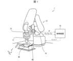
本発明の一実施形態に係るロボット1について、図1を参照して説明する。図1は、本実施形態に係るロボット1の構成を示す模式図である。(Robot configuration)
A robot 1 according to an embodiment of the present invention will be described with reference to FIG. 1. FIG. 1 is a schematic diagram showing the configuration of a robot 1 according to this embodiment.
ロボット1は、任意の動作を直接教示することが可能なロボットである。本実施形態においては、ロボット1に直接教示する動作として、第1部材W1(例えば、金属カラー)の開口又は凹部に第2部材W2(例えば、金属ピン)を圧入する圧入動作を想定する。ただし、ロボット1に直接教示する動作は、任意であり、これに限定されない。 The robot 1 is a robot that can be directly taught any movement. In this embodiment, a press-fitting operation of press-fitting the second member W2 (for example, a metal pin) into an opening or recess of the first member W1 (for example, a metal collar) is assumed as an operation to be directly taught to the robot 1. However, the motion to be directly taught to the robot 1 is arbitrary and is not limited to this.
ロボット1は、図1に示すように、ロボットハンド11と、ロボットアーム12と、力覚センサ13と、操作装置14と、制御装置15と、を備えている。 As shown in FIG. 1, the robot 1 includes a
ロボットハンド11は、ワーク(本実施形態においては第2部材W2)を把持するための機構である。本実施形態においては、ロボットハンド11として、チャックを用いている。ロボットアーム12は、ロボットハンド11を移動するための機構である。本実施形態においては、ロボットアーム12として、垂直多関節アームを用いている。 The
ロボットハンド11は、力覚センサ13を介してロボットアーム12の先端に取り付けられている。力覚センサ13は、ロボットハンド11に作用する3方向(x、y、z軸方向)の力、特に、直接教示においてユーザがロボットハンド11を動かそうとする3方向の力を検出するためのセンサである。本実施形態においては、力覚センサ13として、6軸力覚センサを用いている。ただし、3方向の力を検出することが可能なセンサであれば、どのようなセンサであっても、力覚センサ13として利用することができる。 The
また、ロボットアーム12の先端近傍には、操作装置14が取り付けられている。操作装置14は、ロボットハンド11の1方向(z軸方向)の速度、直接教示においてユーザがロボットハンド11を動かそうとする1方向の速度を指定する操作を受け付けるための装置である。本実施形態においては、操作装置14として、ジョイスティックを用いている。ただし、操作装置14は、1方向の速度を指定する操作を受け付ける可能な装置であれば、どのような装置であっても、操作装置14として利用することができる。 Further, an
制御装置15は、力覚センサ13が検出した力、及び、操作装置14に入力された操作量(本実施形態においてはジョイスティックの傾き)に応じてロボットハンド11の位置を決定し、決定した位置にロボットハンド11が移動するようロボットアーム12に命令する。そして、制御装置15は、ロボットアームへの命令を教示データとして記録する。これにより、教示(ティーチング)が実現される。本実施形態においては、制御装置15として、PC(Personal Computer)を用いている。ただし、後述する制御装置15の機能を実現できる装置であれば、どのような装置であっても、制御装置15として利用することができる。 The
制御装置15は、第1の動作モード及び第2の動作モードの何れかにおいて動作する。ここで、第1の動作モードは、力覚センサ13が検出した3方向の力Fx,Fy,Fzに応じて、ロボットハンド11の3方向の位置x,y,zをアドミタンス制御(力入力・運動出力型制御)により決定する動作モードである。第2の動作モードは、力覚センサ13が検出した2方向の力Fx,Fyに応じて、ロボットハンド11の2方向の位置x,yをアドミタンス制御すると共に、操作装置14に入力された操作量θに応じて、ロボットハンド11の1方向の位置zを速度制御により決定するモードである。以下、制御装置15の機能について、詳細に説明する。The
(制御部の機能)
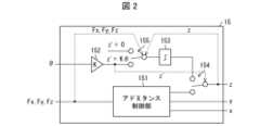
ロボット1が備える制御装置15の機能について、図2を参照して説明する。図2は、制御装置15の機能を示す機能ブロック図である。(Control unit function)
The functions of the
制御装置15は、アドミタンス制御部151と、乗算部152と、積分部153と、モードスイッチ154と、を備えている。制御装置15には、力覚センサ13が検出した3方向の力Fx,Fy,Fzと、操作装置14に入力された操作量θ(例えば、ジョイスティックの傾き)と、が入力される。なお、力Fx,Fy,Fzは、力覚センサ13が検出した力そのものであってもよいし、力覚センサ13が検出した力を不感帯で整形したものであってもよい。The
アドミタンス制御部151は、第1の動作モードにおいて、力覚センサ13が検出した3方向の力Fx,Fy,Fzに応じて、ロボットハンド11の3方向の位置x,y,zをアドミタンス制御によって決定する。具体的には、下記の運動方程式(1)を解く(積分する)ことによって、ロボットハンド11の3方向の位置x,y,zを決定する。In the first operation mode, the
ここで、x’は、位置xの1階微分dx/dt(速度)を表し、x”は、位置xの2階微分d2x/dt2(加速度)を表す。また、y’は、位置yの1階微分dy/dt(速度)を表し、y”は、位置yの2階微分d2y/dt2(加速度)を表す。また、z’は、位置zの1階微分dz/dt(速度)を表し、z”は、位置zの2階微分d2z/dt2(加速度)を表す。また、mx,my,mxは、仮想質量を表す定数(例えば、10kg)である。また、cx,cy,cxは、仮想粘性係数を表す定数(例えば、100kg/s)である。また、αx,αy,αzは、力感度を示す定数(例えば、1)である。なお、位置xは、上記以外の運動方程式、例えば、x’=αxFxを解くことによって算出してもよい。位置y及び位置zについても、同様である。Here, x' represents the first differential dx/dt (velocity) of the position x, and x'' represents the second differential d2 x/dt2 (acceleration) of the position x. represents the first-order differential dy/dt (velocity) of the position y, and y'' represents the second-order differential d2 y/dt2 (acceleration) of the position y. Further, z' represents the first-order differential dz/dt (velocity) of the position z,and z'' represents the second-order differential d2 z/dt2 (acceleration ) of the position z. , mx are constants representing virtual mass (for example, 10 kg). Also, cx , cy , cx are constants representing virtual viscosity coefficients (for example, 100 kg/s). , αy , αz are constants (for example, 1) that indicate force sensitivity.The position x may also be calculated by solving an equation of motion other than the above, for example, x'=αx Fx . Good. The same applies to position y and position z.
また、アドミタンス制御部151は、第2の動作モードにおいて、力覚センサ13が検出した2方向の力Fx,Fyに応じて、ロボットハンド11の2方向の位置x,yをアドミタンス制御によって決定する。具体的には、下記の運動方程式(2a)を解く(積分する)ことによって、ロボットハンド11の2方向の位置x,yを決定する。Further, in the second operation mode, the
ここで、x’は、位置xの1階微分dx/dt(速度)を表し、x”は、位置xの2階微分d2x/dt2(加速度)を表す。また、y’は、位置yの1階微分dy/dt(速度)を表し、y”は、位置yの2階微分d2y/dt2(加速度)を表す。また、z’は、位置zの1階微分dz/dt(速度)を表す。また、mx,myは、仮想質量を表す定数(例えば、10kg)である。また、cx,cyは、仮想粘性係数を表す定数(例えば、200kg/s)である。また、αx,αyは、力感度を示す定数(例えば、1)である。なお、位置xは、上記以外の運動方程式、例えば、x’=αxFxを解くことによって算出してもよい。位置yについても、同様である。Here, x' represents the first differential dx/dt (velocity) of the position x, and x'' represents the second differential d2 x/dt2 (acceleration) of the position x. represents the first-order differential dy/dt (velocity) of the position y, and y'' represents the second-order differential d2 y/dt2 (acceleration) of the position y. Moreover, z' represents the first-order differential dz/dt (velocity) of the position z. Moreover, mx and my are constants (for example, 10 kg) representing virtual mass. Further, cx and cy are constants (for example, 200 kg/s) representing virtual viscosity coefficients. Further, αx and αy are constants (for example, 1) indicating force sensitivity. Note that the position x may be calculated by solving an equation of motion other than the above, for example, x'=αx Fx . The same applies to position y.
乗算部152及び積分部153は、第2の動作モードにおいて、操作装置14に入力された操作量θに応じて、ロボットハンド11の残り1方向の位置zを速度制御により決定する。具体的には、下記の運動方程式(2b)を解く(積分する)ことによって、ロボットハンド11の残り1方向の位置zを決定する。 In the second operation mode, the
ここで、Kは、操作量θを速度z’に変換する変換係数(例えば、0.0005)である。なお、位置zは、上記以外の運動方程式、例えば、z”=-(c/mz)z’+(αz/mz)θを解くことによって算出してもよい。Here, K is a conversion coefficient (for example, 0.0005) that converts the manipulated variable θ into speed z'. Note that the position z may be calculated by solving a motion equation other than the above, for example, z''=-(c/mz )z'+(αz /mz )θ.
モードスイッチ154は、操作装置14に入力された操作量θに応じて、動作モードを切り替えるためのスイッチである。具体的には、θ=0である場合、すなわち、z’=0である場合、動作モードを第1の動作モードに切り替え、θ≠0である場合、すなわち、z’≠0である場合、動作モードを第2の動作モードに切り替える。 The
以上の構成によれば、第1の動作モードにおいて、力覚センサ13が検出した3方向の力Fx,Fy,Fzに応じて、ロボットハンド11の3方向の位置x,y,zをアドミタンス制御により決定することができる。すなわち、第1の動作モードにおいては、ロボットハンド11を動かそうとするユーザの力を、制御装置15によるロボットアーム12の制御によってアシストすることができる。これにより、ユーザは、より小さい力でより精密な直接教示を行うことができる。According to the above configuration, in the first operation mode, the position x, y, z of the
ただし、ロボットハンド11を動かそうとするユーザの力に加えて、z軸方向の反力がワークからロボットハンド11に作用する場合がある。例えば、圧入作業においては、ロボットハンド11を動かそうとするユーザの力に加えて、z軸方向の反力が第2部材W2からのロボットハンド11に作用する。このような場合、3方向のアドミタンス制御を行う第1の動作モードにおいては、ユーザの望む位置にロボットハンド11を移動することが困難になる。 However, in addition to the force of the user trying to move the
これに対して、上記の構成によれば、第2の動作モードにおいて、力覚センサ13が検出した2方向の力Fx,Fyに応じて、ロボットハンド11の2方向の位置x,yをアドミタンス制御により決定すると共に、操作装置14に入力された操作量θに応じて、ロボットハンド11の1方向の位置zを速度制御により決定することができる。したがって、z軸方向の反力がワークからロボットハンド11に作用する場合であっても、動作モードを第1の動作モードから第2の動作モードに切り替えることによって、ユーザの望む位置にロボットハンド11を移動することが容易になる。On the other hand, according to the above configuration, in the second operation mode, the positions x and y of the
なお、第1の動作モードから第2の動作モードへの切り替えは、操作装置14の操作量θが0でなくなったことをトリガーとして生じる。例えば、操作装置14がジョイスティックである場合、ユーザがジョイスティックに触れ、ジョイスティックが傾き始めた時点で第1の動作モードから第2の動作モードへの切り替えが生じる。したがって、ユーザは、動作モードの切り替えを特に意識することなく、自然な操作で操作装置14を用いた制御に移行することができる。 Note that switching from the first operation mode to the second operation mode is triggered by the operation amount θ of the operating
更に、制御装置15は、安全スイッチ155を備えている。安全スイッチ155は、第2の動作モードにおいて、力覚センサ13が検出した力Fx,Fy,Fz、及び、ロボットハンド11の位置zに応じて、ロボットハンド11の速度z’を0にする(z軸方向の動きを止める)ためのスイッチである。具体的には、z0を予め定められた定数として、z>z0であり、且つ、Fx≠0、Fy≠0、又はFz≠0である場合、ロボットハンドの速度z’を0に設定する。ここで、z0は、例えば、第2部材W2の下面の高さと第1部材W1の上面の高さとが一致するときのロボットハンド11の位置である。Furthermore, the
以上の構成によれば、z>z0であるときに、ロボットハンド11に力が作用すると、操作装置14の操作量θに依らず、ロボットハンド11のz軸方向の速度z’が0になる。このため、例えば、第1部材W1と第2部材W2との間にユーザの手が挟まったときに、ユーザに怪我を負わせる可能性を低減することができる。なお、z≦z0であれば、ロボットハンド11に力が作用しても、ロボットハンド11のz軸方向の速度z’がKθになる。したがって、z軸方向の反力が第2部材W2からロボットハンド11に作用しても、第2部材W2の圧入作業を完遂することができる。 According to the above configuration, when a force is applied to the
(アドミタンス制御部の機能に関する補足)
アドミタンス制御部151は、第2の動作モードにおいて、ロボットハンド11に作用する力Fx,Fyの符号の反転回数nx,nyに応じて、力感度αx,αyを減衰させる機能を有していることが好ましい。具体的には、下記の式(3)に従って、力感度αx,αyを減衰させる機能を有していることが好ましい。下記の式(3)において、rは、減衰率を表す1よりも大きい定数である。(Supplementary information regarding the function of the admittance control section)
The
第1部材W1と第2部材W2との嵌め合いをする際に、圧入作業中にチャタリングが生じることがある。ここで、チャタリングとは、例えば、(1)第2部材W2の側面が第1部材W1のx軸正方向側の開口内壁に衝突してx軸負方向の力Fxを受け、(2)第2部材W2がx軸負方向に移動し、(3)第2部材W2の側面が第1部材W1のx軸負方向側の開口内壁に衝突してx軸正方向の力Fxを受け、(4)第2部材W2がx軸正方向に移動する、といった動作が繰り返されることを指す。これに対して、上記の構成によれば、力Fxの符号が変化する度に力感度αxを減衰させることができるので、チャタリングの発生を抑制することができる。When fitting the first member W1 and the second member W2, chattering may occur during the press-fitting operation. Here, chattering means, for example, (1) the side surface of the second member W2 collides with the inner wall of the opening of the first member W1 in the x-axis positive direction and receives a force Fx in the x-axis negative direction; The second member W2 moves in the negative direction of the x-axis, (3) the side surface of the second member W2 collides with the inner wall of the opening of the first member W1 on the negative side of the x-axis, and receives a force Fx in the positive direction of the x-axis, ( 4) Refers to the repetition of an operation in which the second member W2 moves in the positive direction of the x-axis. On the other hand, according to the above configuration, the force sensitivity αx can be attenuated every time the sign of the force Fx changes, so that the occurrence of chattering can be suppressed.
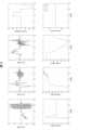
図3は、アドミタンス制御部151が本機能を有さない場合に得られる、力覚センサ13が検出した力Fx,Fy,Fz、操作装置14に入力された操作量θ、ロボットハンド11の位置x,y,z、及び、力感度αx,αyの時間変化を示すグラフである。力感度αx,αyが一定であるため、力Fx,Fy,Fz及び位置yが小刻みに振動するチャタリングが生じていることが見て取れる。FIG. 3 shows the forces Fx , Fy , Fz detected by the
図4は、アドミタンス制御部151が本機能を有する場合に得られる、力覚センサ13が検出した力Fx,Fy,Fz、操作装置14に入力された操作量θ、ロボットハンド11の位置x,y,z、及び、力感度αx,αyの時間変化を示すグラフである。力感度αx,αyが急減衰するため、制御装置15が本機能を有さない場合に生じるチャタリングが抑制されていることが見て取れる。FIG. 4 shows the forces Fx , Fy , Fz detected by the
(付記事項)
本発明は、上述した各実施形態に限定されるものでなく、請求項に示した範囲で種々の変更が可能である。上述した実施形態に含まれる各技術的手段を適宜組み合わせて得られる実施形態についても、本発明の技術的範囲に含まれる。(Additional notes)
The present invention is not limited to the embodiments described above, and various modifications can be made within the scope of the claims. Embodiments obtained by appropriately combining technical means included in the embodiments described above are also included in the technical scope of the present invention.
1 ・・・ロボット
11・・・ロボットハンド
12・・・ロボットアーム
13・・・力覚センサ
14・・・操作装置
15・・・制御装置1...
Claims (12)
Translated fromJapanese前記ロボットアームに取り付けられたロボットハンドと、
前記ロボットハンドに作用する力を検出する力覚センサと、
前記力覚センサにより検出された力に応じて、前記ロボットハンドの位置をアドミタンス制御により決定し、決定した位置に前記ロボットハンドを移動するよう前記ロボットアームに命令すると共に、前記ロボットアームへの命令を教示データとして記録する制御装置と、を備えている、
ことを特徴とするロボット。robot arm and
a robot hand attached to the robot arm;
a force sensor that detects a force acting on the robot hand;
Determining the position of the robot hand by admittance control in accordance with the force detected by the force sensor, instructing the robot arm to move the robot hand to the determined position, and instructing the robot arm. a control device that records the information as teaching data;
A robot characterized by:
前記制御装置は、
第1の動作モードにおいて、前記力覚センサにより検出された3方向の力に応じて、前記ロボットハンドの3方向の位置をアドミタンス制御により決定し、
第2の動作モードにおいて、前記力覚センサにより検出された2方向の力に応じて、前記ロボットハンドの2方向の位置をアドミタンス制御により決定すると共に、前記操作装置に入力された操作量に応じて、前記ロボットハンドの残り1方向の位置を速度制御により決定する、
ことを特徴とする請求項1に記載のロボット。further comprising an operating device;
The control device includes:
In a first operation mode, positions of the robot hand in three directions are determined by admittance control according to forces in three directions detected by the force sensor;
In the second operation mode, the position of the robot hand in two directions is determined by admittance control according to the forces in two directions detected by the force sensor, and the position of the robot hand is determined according to the amount of operation input to the operation device. and determining the position of the robot hand in one remaining direction by speed control.
The robot according to claim 1, characterized in that:
ことを特徴とする請求項2に記載のロボット。In the first operation mode, the control device solves an equation of motion including forces Fx , Fy , Fz detected by the force sensors and force sensitivities αx , αy , αz . , determining the position x, y, z of the robot hand;
The robot according to claim 2, characterized in that:
ことを特徴とする請求項3に記載のロボット。
The robot according to claim 3, characterized in that:
ことを特徴とする請求項2~4の何れか一項に記載のロボット。In the second operation mode, the control device solves the first equation of motion including the forces Fx , Fy detected by the force sensor and the force sensitivities αx , αy , αz . , determining the position z of the robot hand by determining the positions x and y of the robot hand and solving a second equation of motion including the operation amount θ input to the operation device;
The robot according to any one of claims 2 to 4, characterized in that:
ことを特徴とする請求項5に記載のロボット。
The robot according to claim 5, characterized in that:
ことを特徴とする請求項5又は6に記載のロボット。In the second operation mode, the control device attenuates the force sensitivities αx and αy according to the number of times the sign of the force detected by the force sensor is reversed.
The robot according to claim 5 or 6, characterized in that:
ことを特徴とする請求項2~7の何れか一項に記載のロボット。In the second operation mode, the control device controls the robot hand so that the speed of the robot hand in the one direction becomes zero according to the force detected by the force sensor and the position of the robot hand. determining a position in the one direction of
The robot according to any one of claims 2 to 7, characterized in that:
ことを特徴とする請求項2~8の何れか一項に記載のロボット。The operating device is a joystick attached to the robot arm, and the operating amount is a tilt of the joystick.
The robot according to any one of claims 2 to 8, characterized in that:
ことを特徴とする請求項1~9の何れか一項に記載のロボット。The operation to be taught is the operation of press-fitting the second member into the opening or recess of the first member.
The robot according to any one of claims 1 to 9, characterized in that:
前記力覚センサにより検出された力に応じて、前記ロボットハンドの位置をアドミタンス制御により決定し、決定した位置に前記ロボットハンドを移動するよう前記ロボットアームに命令すると共に、前記ロボットアームへの命令を教示データとして記録する制御工程を含んでいる、
ことを特徴とするロボットの制御方法。A method for controlling a robot comprising a robot arm, a robot hand attached to the robot arm, and a force sensor that detects a force acting on the robot hand, the method comprising:
Determining the position of the robot hand by admittance control in accordance with the force detected by the force sensor, instructing the robot arm to move the robot hand to the determined position, and instructing the robot arm. It includes a control process to record as teaching data,
A robot control method characterized by:
第2の動作モードにおいて、前記力覚センサにより検出された2方向の力に応じて、前記ロボットハンドの2方向の位置をアドミタンス制御により決定すると共に、操作装置に入力された操作量に応じて、前記ロボットハンドの残り1方向の位置を速度制御により決定する、
ことを特徴とする請求項11に記載のロボットの制御方法。In a first operation mode, positions of the robot hand in three directions are determined by admittance control according to forces in three directions detected by the force sensor;
In the second operation mode, the positions of the robot hand in two directions are determined by admittance control according to the forces in two directions detected by the force sensor, and the positions of the robot hand are determined in accordance with the amount of operation input to the operation device. , determining the position of the robot hand in one remaining direction by speed control;
12. The robot control method according to claim 11.
Priority Applications (5)
| Application Number | Priority Date | Filing Date | Title |
|---|---|---|---|
| JP2022033903AJP2023129112A (en) | 2022-03-04 | 2022-03-04 | Robot and control method of the same |
| KR1020230024618AKR20230131121A (en) | 2022-03-04 | 2023-02-23 | Robot and method of controlling the same |
| US18/173,342US12318925B2 (en) | 2022-03-04 | 2023-02-23 | Robot and method of controlling the same |
| CN202310192286.7ACN116690532A (en) | 2022-03-04 | 2023-03-02 | Robot and control method thereof |
| DE102023105248.9ADE102023105248A1 (en) | 2022-03-04 | 2023-03-03 | Robots and methods for controlling them |
Applications Claiming Priority (1)
| Application Number | Priority Date | Filing Date | Title |
|---|---|---|---|
| JP2022033903AJP2023129112A (en) | 2022-03-04 | 2022-03-04 | Robot and control method of the same |
Publications (1)
| Publication Number | Publication Date |
|---|---|
| JP2023129112Atrue JP2023129112A (en) | 2023-09-14 |
Family
ID=87572219
Family Applications (1)
| Application Number | Title | Priority Date | Filing Date |
|---|---|---|---|
| JP2022033903APendingJP2023129112A (en) | 2022-03-04 | 2022-03-04 | Robot and control method of the same |
Country Status (5)
| Country | Link |
|---|---|
| US (1) | US12318925B2 (en) |
| JP (1) | JP2023129112A (en) |
| KR (1) | KR20230131121A (en) |
| CN (1) | CN116690532A (en) |
| DE (1) | DE102023105248A1 (en) |
Families Citing this family (2)
| Publication number | Priority date | Publication date | Assignee | Title |
|---|---|---|---|---|
| US20240019238A1 (en)* | 2022-07-13 | 2024-01-18 | Sintokogio, Ltd. | Measurement system and checking method |
| CN117207247B (en)* | 2023-10-30 | 2025-08-19 | 中国科学院重庆绿色智能技术研究院 | Reachability test system and method for cooperative robot |
Citations (2)
| Publication number | Priority date | Publication date | Assignee | Title |
|---|---|---|---|---|
| JPS63162180A (en)* | 1986-12-23 | 1988-07-05 | キヤノン株式会社 | Robot teaching method |
| JP2019529149A (en)* | 2016-09-28 | 2019-10-17 | ガイオットー オートメーション エス.ピー.アー. | Article surface treatment method |
Family Cites Families (26)
| Publication number | Priority date | Publication date | Assignee | Title |
|---|---|---|---|---|
| JPH029553A (en) | 1988-06-07 | 1990-01-12 | Mitsubishi Electric Corp | Work type automatic discrimination device |
| JPH0830133A (en) | 1994-07-12 | 1996-02-02 | Ricoh Co Ltd | Fixing device |
| JPH1176911A (en) | 1997-09-09 | 1999-03-23 | Asahi Sanac Kk | Paint tool with acceleration sensor |
| US20090192523A1 (en) | 2006-06-29 | 2009-07-30 | Intuitive Surgical, Inc. | Synthetic representation of a surgical instrument |
| US20090090795A1 (en) | 2007-10-04 | 2009-04-09 | Ray Charles D | Surface painting system |
| JP2009274191A (en) | 2008-05-17 | 2009-11-26 | National Univ Corp Shizuoka Univ | Working robot and computer program applied to the working robot |
| CN102292194B (en) | 2009-08-21 | 2015-03-04 | 松下电器产业株式会社 | Robot arm control device and control method, assembly robot, robot arm control program, and robot arm control integrated circuit |
| CN102300679B (en) | 2009-09-28 | 2014-12-10 | 松下电器产业株式会社 | Robot arm control device and control method, robot and integrated circuit for robot arm control |
| EP3200718A4 (en)* | 2014-09-30 | 2018-04-25 | Auris Surgical Robotics, Inc | Configurable robotic surgical system with virtual rail and flexible endoscope |
| WO2017033365A1 (en) | 2015-08-25 | 2017-03-02 | 川崎重工業株式会社 | Remote control robot system |
| US10272568B2 (en)* | 2015-09-17 | 2019-04-30 | Canon Kabushiki Kaisha | Robot apparatus, robot controlling method, program, recording medium, and assembly manufacturing method |
| JP2018015857A (en) | 2016-07-29 | 2018-02-01 | セイコーエプソン株式会社 | Control device and robot |
| WO2018183937A1 (en) | 2017-03-31 | 2018-10-04 | Canvas Construction, Inc. | Automated insulation application system and method |
| US10537995B2 (en) | 2017-05-08 | 2020-01-21 | Seiko Epson Corporation | Controller and control method of robot, and robot system |
| JP7427358B2 (en) | 2017-07-20 | 2024-02-05 | キヤノン株式会社 | Robot system, article manufacturing method, control method, control program, and recording medium |
| JP2019081236A (en) | 2017-10-31 | 2019-05-30 | セイコーエプソン株式会社 | Simulation device, control device and robot |
| JP7080649B2 (en) | 2018-01-17 | 2022-06-06 | キヤノン株式会社 | Control method, manufacturing method of goods, control program, recording medium, robot system, control device |
| JP6973119B2 (en) | 2018-01-26 | 2021-11-24 | セイコーエプソン株式会社 | Robot control device and robot system |
| JP7483321B2 (en) | 2018-02-13 | 2024-05-15 | キヤノン株式会社 | Control device, control method, robot system, article manufacturing method, display device, program, and recording medium |
| JP7067107B2 (en) | 2018-02-19 | 2022-05-16 | セイコーエプソン株式会社 | Robot control device and robot system |
| JP6881361B2 (en)* | 2018-03-14 | 2021-06-02 | オムロン株式会社 | Robot control device, robot and control method |
| JP7124439B2 (en) | 2018-05-22 | 2022-08-24 | セイコーエプソン株式会社 | Control device and robot system |
| EP3912769A4 (en) | 2019-01-18 | 2023-01-18 | Kabushiki Kaisha Yaskawa Denki | Robot control system and robot control method |
| DE112021000634T5 (en) | 2020-01-20 | 2022-11-03 | Fanuc Corporation | ROBOT SIMULATION DEVICE |
| JP7392161B2 (en) | 2020-07-31 | 2023-12-05 | ファナック株式会社 | Robot system and robot control device |
| US11673264B2 (en)* | 2021-03-25 | 2023-06-13 | Mitsubishi Electric Research Laboratories, Inc. | System and method for robotic assembly based on adaptive compliance |
- 2022
- 2022-03-04JPJP2022033903Apatent/JP2023129112A/enactivePending
- 2023
- 2023-02-23USUS18/173,342patent/US12318925B2/enactiveActive
- 2023-02-23KRKR1020230024618Apatent/KR20230131121A/enactivePending
- 2023-03-02CNCN202310192286.7Apatent/CN116690532A/enactivePending
- 2023-03-03DEDE102023105248.9Apatent/DE102023105248A1/enactivePending
Patent Citations (2)
| Publication number | Priority date | Publication date | Assignee | Title |
|---|---|---|---|---|
| JPS63162180A (en)* | 1986-12-23 | 1988-07-05 | キヤノン株式会社 | Robot teaching method |
| JP2019529149A (en)* | 2016-09-28 | 2019-10-17 | ガイオットー オートメーション エス.ピー.アー. | Article surface treatment method |
Also Published As
| Publication number | Publication date |
|---|---|
| DE102023105248A1 (en) | 2023-09-07 |
| KR20230131121A (en) | 2023-09-12 |
| US20230278195A1 (en) | 2023-09-07 |
| CN116690532A (en) | 2023-09-05 |
| US12318925B2 (en) | 2025-06-03 |
Similar Documents
| Publication | Publication Date | Title |
|---|---|---|
| JP2023129112A (en) | Robot and control method of the same | |
| Aliaga et al. | Experimental quantitative comparison of different control architectures for master-slave teleoperation | |
| Dubey et al. | Variable damping impedance control of a bilateral telerobotic system | |
| JP2008110406A (en) | Robot direct teaching device | |
| US9300430B2 (en) | Latency smoothing for teleoperation systems | |
| JPH0683976B2 (en) | Compliance control method | |
| Luo et al. | Control design of robot for compliant manipulation on dynamic environments | |
| Hwang et al. | Toward event-based haptics: Rendering contact using open-loop force pulses | |
| WO2021149563A1 (en) | Robot simulation device | |
| JP2016182649A (en) | Robot controller and robot system | |
| CN112601863A (en) | Construction machine and evaluation device | |
| JP2019020826A (en) | Force control device, force control method, and force control program | |
| JP2004364396A (en) | Motor control device and control method | |
| Cho et al. | Impedance control with variable damping for bilateral teleoperation under time delay | |
| JPH03161289A (en) | How to control master/slave robots | |
| JPH06262569A (en) | Robot controller | |
| JP2008217260A (en) | Force display device | |
| JP2023007691A (en) | Method for setting robot control parameter, robot system, and computer program | |
| JP7401262B2 (en) | robot system | |
| JPS62297080A (en) | Master slave manipulator | |
| JP3618363B2 (en) | Robot controller | |
| JPH06206185A (en) | Robot controller | |
| JP6743431B2 (en) | Control device and robot system | |
| KR102643316B1 (en) | Detecting device and method for calculating amount of impact of robot manipulator | |
| JP7730107B2 (en) | Learning support system, learning support method, and learning support program |
Legal Events
| Date | Code | Title | Description |
|---|---|---|---|
| A621 | Written request for application examination | Free format text:JAPANESE INTERMEDIATE CODE: A621 Effective date:20241119 | |
| A131 | Notification of reasons for refusal | Free format text:JAPANESE INTERMEDIATE CODE: A131 Effective date:20250722 | |
| A977 | Report on retrieval | Free format text:JAPANESE INTERMEDIATE CODE: A971007 Effective date:20250723 | |
| A521 | Request for written amendment filed | Free format text:JAPANESE INTERMEDIATE CODE: A523 Effective date:20250908 |