JP2023127179A - In-vehicle device, information processing method, and program - Google Patents
In-vehicle device, information processing method, and programDownload PDFInfo
- Publication number
- JP2023127179A JP2023127179AJP2022030801AJP2022030801AJP2023127179AJP 2023127179 AJP2023127179 AJP 2023127179AJP 2022030801 AJP2022030801 AJP 2022030801AJP 2022030801 AJP2022030801 AJP 2022030801AJP 2023127179 AJP2023127179 AJP 2023127179A
- Authority
- JP
- Japan
- Prior art keywords
- user
- vehicle
- line
- sight
- camera
- Prior art date
- Legal status (The legal status is an assumption and is not a legal conclusion. Google has not performed a legal analysis and makes no representation as to the accuracy of the status listed.)
- Pending
Links
Images


Landscapes
- Fittings On The Vehicle Exterior For Carrying Loads, And Devices For Holding Or Mounting Articles (AREA)
- Traffic Control Systems (AREA)
Abstract
Translated fromJapaneseDescription
Translated fromJapanese本発明は、車載装置、情報処理方法、および、プログラムに関する。 The present invention relates to an in-vehicle device, an information processing method, and a program.
車両における運転者の姿勢を検出し、運転者の状態(例えば眠気)を判定する技術がある(特許文献1参照)。 There is a technology that detects the driver's posture in a vehicle and determines the driver's condition (for example, drowsiness) (see Patent Document 1).
しかしながら、上記技術では、運転者(ユーザともいう)の状態を適切に判定できないことがある。 However, with the above technology, it may not be possible to appropriately determine the condition of the driver (also referred to as the user).
そこで、本発明は、ユーザの状態を適切に判定し得る車載装置などを提供する。 Therefore, the present invention provides an in-vehicle device and the like that can appropriately determine a user's condition.
本発明の一態様に係る車載装置は、車両の車室内の天井の近傍の位置に設置されるカメラであって、前記車室内にいるユーザが撮影された画像を生成するカメラと、前記カメラが生成した前記画像に映っている前記ユーザの視線を検出する検出部と、前記検出部が検出した前記ユーザの前記視線が、前記車両が備えるルームミラーを含む所定領域に向けられているか否かの判定をする判定部と、前記カメラが生成した画像から前記ユーザの状態を推定し、推定した前記状態を示す状態情報を生成する推定部と、前記推定部が生成した前記状態情報を、前記判定部による判定結果を用いて補正する補正部と、前記補正部が補正した後の前記状態情報を提示する提示部とを備える車載装置である。 An in-vehicle device according to one aspect of the present invention is a camera installed near a ceiling in a vehicle interior of a vehicle, and includes a camera that generates an image of a user in the vehicle interior, and a camera that generates an image of a user in the vehicle interior. a detection unit that detects the user's line of sight reflected in the generated image; and a detection unit that detects whether the user's line of sight detected by the detection unit is directed toward a predetermined area including a rearview mirror provided in the vehicle. a determination unit that makes a determination; an estimation unit that estimates the state of the user from an image generated by the camera and generates state information indicating the estimated state; The present invention is an in-vehicle device that includes a correction section that performs correction using a determination result made by the correction section, and a presentation section that presents the state information after the correction section has corrected it.
なお、これらの包括的または具体的な態様は、システム、装置、集積回路、コンピュータプログラムまたはコンピュータ読み取り可能なCD-ROMなどの記録媒体で実現されてもよく、システム、装置、集積回路、コンピュータプログラムおよび記録媒体の任意な組み合わせで実現されてもよい。 Note that these comprehensive or specific aspects may be realized by a system, a device, an integrated circuit, a computer program, or a computer-readable recording medium such as a CD-ROM, and the system, device, integrated circuit, computer program and a recording medium may be used in any combination.
本発明の撮影装置は、ユーザの状態を適切に判定することができる。 The photographing device of the present invention can appropriately determine the user's condition.
(本発明の基礎となった知見)
本発明者は、「背景技術」の欄において記載した、運転者の状態を推定する技術について、以下の問題が生じることを見出した。(Findings that formed the basis of the present invention)
The present inventor has discovered that the following problem occurs with the technology for estimating the driver's condition described in the "Background Art" section.
車室内において運転者を撮影するカメラが、運転席の前方の位置に設置されることがある(例えば特許文献1参照)。運転席の前方の位置に設置されているカメラから運転者を撮影する場合、運転者の身体が、ハンドル、または、ハンドルを把持する運転者の手の陰になってしまい、運転者が適切に撮影されないことがある。運転者が適切に撮影されない場合、運転者の状態の推定が適切になされない。 A camera that photographs the driver inside the vehicle is sometimes installed at a position in front of the driver's seat (see, for example, Patent Document 1). When photographing the driver from a camera installed in front of the driver's seat, the driver's body may be in the shadow of the steering wheel or the driver's hands gripping the steering wheel, making it difficult for the driver to properly capture the image. Sometimes the picture is not taken. If the driver is not properly photographed, the driver's condition cannot be properly estimated.
一方、運転者を撮影するカメラが、車室内の天井またはルームミラーの近傍の位置に設置されることがある。車室内の天井またはルームミラーの近傍の位置に設置されたカメラによれば、ハンドルまたは運転者の手の陰になることなく、運転者の身体が適切に撮影され得る。 On the other hand, a camera that photographs the driver is sometimes installed on the ceiling of the vehicle interior or near the rearview mirror. If the camera is installed on the ceiling of the vehicle interior or near the rearview mirror, the driver's body can be appropriately photographed without being in the shadow of the steering wheel or the driver's hands.
ところで、運転者が適切な状態で車両を運転しているときには、運転者は適度な時間間隔(例えば数秒~数十秒程度)ごとにルームミラーに視線を向けて車両の後方の光景を確認していることが知られている。運転者の適切な状態とは、運転に適した状態であり、言い換えれば、眠気を感じていない状態、または、漫然でない状態などである。 By the way, when the driver is driving the vehicle in appropriate conditions, the driver turns his eyes to the rearview mirror at moderate intervals (for example, every few seconds to several tens of seconds) to check the scene behind the vehicle. It is known that The appropriate state of the driver is a state suitable for driving, in other words, a state where the driver does not feel sleepy or a state where the driver is not distracted.
運転者の視線は、運転者が映っている画像に対する視線検出処理によって解析され得る。視線検出技術では、画像に映っている運転者の目における眼球(虹彩または瞳孔など)の位置の検出を用いて視線を検出するので、運転者が視線を向ける対象の近傍に設置されているカメラにより撮影された画像を用いることで、その対象に視線が向けられているか否かをより明確に判定できる。 The driver's line of sight can be analyzed by line of sight detection processing on an image in which the driver is shown. Line-of-sight detection technology detects line-of-sight by detecting the position of the driver's eyeball (iris or pupil, etc.) in the image. By using the image taken by the user, it is possible to more clearly determine whether the user's line of sight is directed toward the target.
そこで、車室内の天井の近傍(より特定的には、ルームミラーの近傍)に設置されたカメラが撮影した画像を用いた視線検出処理により、ユーザがルームミラーに視線を向けているか否かをより明確に判定でき、この判定に基づいて運転者の状態をより適切に判定できるとの知見を本願発明者は得た。 Therefore, a line of sight detection process using images taken by a camera installed near the ceiling of the vehicle interior (more specifically, near the rearview mirror) is used to detect whether the user is directing his/her line of sight toward the rearview mirror. The inventors of the present invention have found that the determination can be made more clearly, and the driver's condition can be determined more appropriately based on this determination.
本発明の一態様に係る車載装置は、車両の車室内の天井の近傍の位置に設置されるカメラであって、前記車室内にいるユーザが撮影された画像を生成するカメラと、前記カメラが生成した前記画像に映っている前記ユーザの視線を検出する検出部と、前記検出部が検出した前記ユーザの前記視線が、前記車両が備えるルームミラーを含む所定領域に向けられているか否かの判定をする判定部と、前記カメラが生成した画像から前記ユーザの状態を推定し、推定した前記状態を示す状態情報を生成する推定部と、前記推定部が生成した前記状態情報を、前記判定部による判定結果を用いて補正する補正部と、前記補正部が補正した後の前記状態情報を提示する提示部とを備える車載装置である。 An in-vehicle device according to one aspect of the present invention is a camera installed near a ceiling in a vehicle interior of a vehicle, and includes a camera that generates an image of a user in the vehicle interior, and a camera that generates an image of a user in the vehicle interior. a detection unit that detects the user's line of sight reflected in the generated image; and a detection unit that detects whether the user's line of sight detected by the detection unit is directed toward a predetermined area including a rearview mirror provided in the vehicle. a determination unit that makes a determination; an estimation unit that estimates the state of the user from an image generated by the camera and generates state information indicating the estimated state; The present invention is an in-vehicle device that includes a correction section that performs correction using a determination result made by the correction section, and a presentation section that presents the state information after the correction section has corrected it.
上記態様によれば、車載装置は、ユーザがルームミラーに視線を向けているか否かを適切に判定し、その判定結果を用いて、ユーザの推定される状態を補正することで、ユーザの状態をより適切に判定することができる。特に、車室内の天井の近傍に設置されたカメラを用いるので、ユーザがルームミラーに視線を向けているか否かをより適切に判定することができ、最終的なユーザの状態の判定結果がより適切なものとなる効果がある。このように、車載装置は、ユーザの状態を適切に判定することができる。 According to the above aspect, the in-vehicle device appropriately determines whether or not the user is directing his or her gaze toward the rearview mirror, and uses the determination result to correct the estimated state of the user. can be determined more appropriately. In particular, since a camera installed near the ceiling inside the vehicle is used, it is possible to more appropriately determine whether the user is looking at the rearview mirror, and the final determination result of the user's condition is improved. It has the effect of making it appropriate. In this way, the in-vehicle device can appropriately determine the user's condition.
例えば、前記カメラは、前記ユーザを複数回撮影することで、複数の前記画像を生成し、前記判定部は、前記判定において、さらに、複数の前記画像を用いて前記検出部が検出した前記ユーザの前記視線の時間的変化から、前記ユーザの視線が適正な時間間隔で前記所定領域に向けられているか否かを判定してもよい。 For example, the camera generates a plurality of images by photographing the user a plurality of times, and in the determination, the determination unit further determines that the detection unit detects the user using the plurality of images. From the temporal change in the line of sight, it may be determined whether the user's line of sight is directed toward the predetermined area at appropriate time intervals.
上記態様によれば、車載装置は、ユーザがルームミラーに視線を向けるタイミングの時間間隔が適正であるか否かをさらに判定することで、ユーザの推定される状態を補正し、ユーザの状態をより適切に判定することができる。よって、車載装置は、ユーザの状態をより適切に判定することができる。 According to the above aspect, the in-vehicle device corrects the estimated state of the user by further determining whether the time interval between when the user looks at the rearview mirror is appropriate, and the in-vehicle device corrects the estimated state of the user. More appropriate judgment can be made. Therefore, the in-vehicle device can more appropriately determine the user's condition.
例えば、前記提示部は、表示画面を備える電子ミラーである前記ルームミラーを含み、前記車載装置は、さらに、前記提示部が前記表示画面に情報を提示したタイミングにおいて前記カメラによる撮影により生成された前記画像から、前記検出部により得られる前記ユーザの視線が向けられている領域を含むように、前記所定領域を調整する第一調整部を備え、前記判定部は、前記第一調整部が調整した後の前記所定領域を用いて前記判定をしてもよい。 For example, the presentation unit includes the room mirror that is an electronic mirror having a display screen, and the in-vehicle device further includes information generated by photographing with the camera at the timing when the presentation unit presents the information on the display screen. The determination unit includes a first adjustment unit that adjusts the predetermined area from the image to include the area where the user's line of sight is directed, which is obtained by the detection unit, and the determination unit The determination may be made using the predetermined area after the determination.
上記態様によれば、車載装置は、所定領域を調整したうえで、調整された所定領域を用いた判定を行う。電子ミラーが情報を提示したタイミングにおいて、ユーザが電子ミラーに視線を向けることが想定されるので、そのときのユーザの視線を用いることにより、当該ユーザの体格または姿勢に応じた所定領域が設定されることが可能であり、これにより、ユーザの推定される状態の補正をより適切にすることができる。よって、車載装置は、ユーザの状態をより適切に判定することができる。 According to the above aspect, the in-vehicle device adjusts the predetermined area and then makes a determination using the adjusted predetermined area. It is assumed that the user turns his/her line of sight to the electronic mirror at the timing when the electronic mirror presents information, so by using the user's line of sight at that time, a predetermined area is set according to the user's physique or posture. This allows the estimated state of the user to be corrected more appropriately. Therefore, the in-vehicle device can more appropriately determine the user's condition.
例えば、前記車両は、前記車両の後方に他の車両が近接していることを感知するセンサを備え、前記車載装置は、さらに、前記車両の後方に他の車両が近接していることを前記センサが感知しているタイミングにおいて前記カメラによる撮影により生成された前記画像から、前記検出部により得られる前記ユーザの視線が向けられている領域を含むように、前記所定領域を調整する第二調整部を備え、前記判定部は、前記第二調整部が調整した後の前記所定領域を用いて前記判定をしてもよい。 For example, the vehicle includes a sensor that detects that another vehicle is close to the rear of the vehicle, and the in-vehicle device further detects that another vehicle is close to the rear of the vehicle. a second adjustment of adjusting the predetermined area so as to include the area to which the user's line of sight obtained by the detection unit is directed from the image generated by photography by the camera at the timing when the sensor is sensing; The determination unit may make the determination using the predetermined area adjusted by the second adjustment unit.
上記態様によれば、車載装置は、所定領域を調整したうえで、調整された所定領域を用いた判定を行う。車両の後方に他の車両が近接していることをセンサが感知したタイミングにおいて、ユーザが電子ミラーに視線を向けることが想定されるので、そのときのユーザの視線を用いることにより、当該ユーザの体格または姿勢に応じた所定領域が設定されることが可能であり、これにより、ユーザの推定される状態の補正をより適切にすることができる。よって、車載装置は、ユーザの状態をより適切に判定することができる。 According to the above aspect, the in-vehicle device adjusts the predetermined area and then makes a determination using the adjusted predetermined area. It is assumed that the user turns his/her line of sight to the electronic mirror at the timing when the sensor detects that another vehicle is approaching behind the vehicle, so by using the user's line of sight at that time, the user's A predetermined area can be set according to the physique or posture, and thereby the estimated state of the user can be corrected more appropriately. Therefore, the in-vehicle device can more appropriately determine the user's condition.
例えば、前記第二調整部は、前記車両の後方に他の車両が近接していることを前記センサが感知している期間を特定し、特定した前記期間内に前記カメラによる複数回の撮影により生成された複数の前記画像を用いて、前記所定領域を調整してもよい。 For example, the second adjustment unit may specify a period during which the sensor is sensing that another vehicle is approaching behind the vehicle, and may be configured to take pictures by the camera multiple times within the specified period. The predetermined area may be adjusted using the plurality of generated images.
上記態様によれば、車載装置は、実際に車両の後方に他の車両が近接している期間に撮影された複数の画像を用いるので、後方に車両が近接していることを認識したユーザがルームミラーに視線を向けて車両の後方を確認する動作をすることを利用して、所定領域の調整をより適切に行うことができる。よって、車載装置は、ユーザの状態をより適切に判定することができる。 According to the above aspect, the in-vehicle device uses a plurality of images taken during a period when another vehicle is actually close to the rear of the vehicle, so that a user who recognizes that a vehicle is close to the rear of the vehicle can Adjustment of a predetermined area can be made more appropriately by using the action of checking the rear of the vehicle by looking at the rearview mirror. Therefore, the in-vehicle device can more appropriately determine the user's condition.
また、本発明の一態様に係る情報処理方法は、車両の車室内の天井の近傍の位置に設置されるカメラにより、前記車室内にいるユーザが撮影された画像を生成し、前記カメラが生成した前記画像に映っている前記ユーザの視線を検出し、検出した前記ユーザの前記視線が、前記車両が備えるルームミラーを含む所定領域に向けられているか否かの判定をし、前記カメラが生成した画像から前記ユーザの状態を推定し、推定した前記状態を示す状態情報を生成し、生成した前記状態情報を、前記判定の結果を用いて補正し、補正した後の前記状態情報を提示する情報処理方法である。 Further, in the information processing method according to one aspect of the present invention, an image of a user in the vehicle interior is generated by a camera installed near a ceiling in the vehicle interior, and an image is generated by the camera. detecting the line of sight of the user reflected in the image, determining whether the detected line of sight of the user is directed toward a predetermined area including a rearview mirror provided in the vehicle; estimating the state of the user from the image, generating state information indicating the estimated state, correcting the generated state information using the result of the determination, and presenting the corrected state information. It is an information processing method.
上記態様によれば、上記車載装置と同様の効果を奏する。 According to the above aspect, the same effects as the above vehicle-mounted device can be achieved.
また、本発明の一態様に係るプログラムは、上記の情報処理方法をコンピュータに実行させるプログラムである。 Further, a program according to one aspect of the present invention is a program that causes a computer to execute the above information processing method.
上記態様によれば、上記撮影装置と同様の効果を奏する。 According to the above aspect, the same effects as the above photographing device can be achieved.
なお、これらの包括的または具体的な態様は、システム、装置、集積回路、コンピュータプログラムまたはコンピュータ読み取り可能なCD-ROMなどの記録媒体で実現されてもよく、システム、装置、集積回路、コンピュータプログラムまたは記録媒体の任意な組み合わせで実現されてもよい。 Note that these comprehensive or specific aspects may be realized by a system, a device, an integrated circuit, a computer program, or a computer-readable recording medium such as a CD-ROM, and the system, device, integrated circuit, computer program Alternatively, it may be realized using any combination of recording media.
以下、実施の形態について、図面を参照しながら具体的に説明する。 Hereinafter, embodiments will be specifically described with reference to the drawings.
なお、以下で説明する実施の形態は、いずれも包括的または具体的な例を示すものである。以下の実施の形態で示される数値、形状、材料、構成要素、構成要素の配置位置及び接続形態、ステップ、ステップの順序などは、一例であり、本発明を限定する主旨ではない。また、以下の実施の形態における構成要素のうち、最上位概念を示す独立請求項に記載されていない構成要素については、任意の構成要素として説明される。 Note that the embodiments described below are all inclusive or specific examples. The numerical values, shapes, materials, components, arrangement positions and connection forms of the components, steps, order of steps, etc. shown in the following embodiments are merely examples, and do not limit the present invention. Further, among the constituent elements in the following embodiments, constituent elements that are not described in the independent claims indicating the most significant concept will be described as arbitrary constituent elements.
(実施の形態)
本実施の形態において、ユーザの状態を適切に判定することができる車載装置および情報処理方法などについて説明する。(Embodiment)
In this embodiment, an in-vehicle device, an information processing method, and the like that can appropriately determine a user's condition will be described.
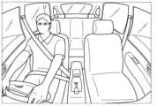
図1は、本実施の形態における車両Vと車載装置1との構成を模式的に示す説明図である。図2は、本実施の形態における車載装置1の機能構成を示すブロック図である。 FIG. 1 is an explanatory diagram schematically showing the configuration of a vehicle V and an on-
車両Vは、例えば自動車であり、人が乗車することができる。車両Vに乗車している人をユーザUという。ユーザUは、例えば車両Vの運転席に着座する運転者であり、この場合を例として説明するが、これに限られず、助手席または後部座席に乗車している乗員でもよい。 The vehicle V is, for example, a car, and a person can ride therein. A person riding in vehicle V is called a user U. The user U is, for example, a driver seated in the driver's seat of the vehicle V, and this case will be described as an example, but the user U is not limited to this, and may be a passenger sitting in the front passenger seat or the rear seat.
車両Vは、ユーザUによって運転されて路面を走行する。車両Vは、乗員が乗車するための空間である車室Sを有する。車室Sには、ルームミラーおよび乗員が着座するためのシートなどが配置されている。 Vehicle V is driven by user U and travels on a road surface. The vehicle V has a cabin S that is a space for passengers to ride. A rearview mirror, a seat for a passenger, and the like are arranged in the vehicle interior S.
車載装置1は、ユーザUの状態を判定する装置である。例えば、車載装置1は、ユーザUの状態として、ユーザUが車両Vの運転に適した状態であるか否かを判定する。運転に適した状態は、例えば、眠気を感じていない状態、漫然でない状態、または、感情的でない状態などである。 The in-
図1および図2に示されるように、車載装置1は、カメラ5と、処理部10と、提示部20とを備える。 As shown in FIGS. 1 and 2, the in-
カメラ5は、車両Vの車室S内に設置される撮影装置である。カメラ5は、車室S内にいるユーザUが撮影された画像を生成する。カメラ5が設置される位置および姿勢については、後で詳しく説明する。 The
処理部10は、ユーザUの状態を判定する処理をする機能部である。処理部10は、カメラ5が生成した画像に対する処理によって画像に映っているユーザUから取得した情報を用いて、ユーザUの状態を判定し、判定結果を出力する。処理部10が実行する処理の詳細は、後で詳しく説明する。処理部10は、車載装置1が備えるプロセッサ(例えばCPU(Central Processing Unit))(不図示)が、メモリ(不図示)を用いて所定のプログラムを実行することで実現され得る。処理部10は、例えば車両Vのダッシュボード内に配置されるが、配置位置はこれに限られない。 The
処理部10は、機能部として、視線検出部11と、判定部12と、状態推定部13と、補正部14とを備える。 The
視線検出部11は、カメラ5が生成した画像に映っているユーザUの視線を検出する。ユーザUの視線の検出は、上記画像に対する周知の視線検出技術によってなされ得る。また、視線検出部11は、ユーザUの頭部の位置および姿勢を取得する。ユーザUの頭部の位置および姿勢は、車両Vにおけるカメラ5の位置および姿勢と、画像に映っているユーザUの頭部の位置および姿勢から得られる、カメラ5に対する相対的なユーザUの位置および姿勢とを用いて算定され得る。視線検出部11は、取得したユーザUの頭部の位置および姿勢と、検出したユーザUの視線とを用いて、ユーザUが視線を向けている位置を示す情報(視線情報ともいう)を生成して判定部12に提供する。視線検出部11を検出部ともいう。 The line of
視線検出部11は、さらに、カメラ5が生成した複数の画像それぞれにおけるユーザUの視線を検出し、上記複数の画像が生成された期間におけるユーザUの視線の時間的変化を取得してもよい。 The line of
判定部12は、ユーザUの視線が所定領域に向けられているか否かの判定をする。所定領域は、少なくとも、車両Vが備えるルームミラーMを含む領域である。具体的には、判定部12は、視線情報を視線検出部11から取得し、取得した視線情報に示される位置が、所定領域に含まれるか否かを判定する。判定部12は、判定の結果を補正部14に提供する。 The determining
なお、所定領域は、ルームミラーMが存在する領域としてあらかじめ定められた領域であってもよいし、実際にユーザUの視線が向けられた領域に基づいて調整されてもよい。調整の方法の例は、後述する変形例で説明される。 Note that the predetermined area may be a predetermined area where the room mirror M exists, or may be adjusted based on the area where the user U's line of sight is actually directed. An example of the method of adjustment will be explained in the modified example described below.
なお、判定部12は、さらに、カメラ5によって生成された複数の画像を用いて視線検出部11が検出したユーザUの視線の時間的変化から、ユーザUの視線が適正な時間間隔で所定領域に向けられているか否かを判定してもよい。 Note that the
状態推定部13は、カメラ5が生成した画像からユーザUの状態を推定する。状態推定部13は、推定したユーザUの状態を示す状態情報を生成して補正部14に提供する。ユーザUの状態は、例えば眠気の度合いでありこの場合を例として説明するが、疲労の度合い、感情、急病の発症の有無、漫然さの度合い、または、脇見の多少などであってもよい。状態推定部13を推定部ともいう。 The
補正部14は、状態推定部13が生成した状態情報を、判定部12による判定の結果を用いて補正する。補正部14は、補正した後の状態情報を提示部20に提供する。具体的には、補正部14は、視線情報に示される位置(つまり、ユーザUが視線を向けている位置)が所定領域に含まれると判定部12が判定した場合に、状態推定部13が生成した状態情報を、ユーザUの状態が車両Vの運転に適した状態であることを示すように補正する。また、補正部14は、視線情報に示される位置が所定領域に含まれないと判定部12が判定した場合に、状態推定部13が生成した状態情報を、ユーザUの状態が車両Vの運転に適さない状態であることを示すように補正する。 The
例えば、ユーザUの状態が、ユーザUの眠気の度合いであり、1(まったく眠くない、覚醒)から6(眠り)の数値で表現される場合において、状態推定部13が眠気の度合いを3と推定することがある。そして、判定部12は、視線情報に示される位置が所定領域に含まれないと判定することがある。その場合、補正部14は、状態推定部13により推定された眠気の度合いを、3より大きい値(例えば4)に補正する。 For example, when the state of user U is the degree of sleepiness of user U and is expressed as a numerical value from 1 (not sleepy at all, awake) to 6 (sleep), the
提示部20は、処理部10(より具体的には補正部14)から提供される状態情報を提示する。提示した結果情報は、ユーザUに視認されることが想定される。提示部20は、例えば、車両Vが搭載しているインフォテインメントシステム(カーナビゲーションシステムを含む)の表示画面への画像の表示によって、結果情報を提示する。なお、提示部20は、インフォテインメントシステムを介して、車両Vの車載スピーカによる音の出力によって、結果情報を提示してもよい。 The
なお、ルームミラーMが、表示画面を備える電子ミラーである場合には、提示部20はルームミラーMの表示画面であってもよい。 In addition, when the room mirror M is an electronic mirror provided with a display screen, the
以降において、カメラ5が設置される位置および姿勢について説明する。カメラ5は、例えば天井に設置され、この場合を主に説明するが、ルームミラーに設置されてもよい。 Hereinafter, the position and posture where the
図3および図4は、実施の形態におけるカメラ5が設置される位置と撮影方向との例を示す説明図である。図3は、車両Vの側面視において、カメラ5が設置される位置と撮影方向との例を示し、図4は、車両Vの上面視において、カメラ5が設置される位置と撮影方向との例を示す。 3 and 4 are explanatory diagrams showing examples of the position where the
図3に示されるように、カメラ5は、例えば、車室S内の天井に設置され、かつ、カメラ5の撮影方向6が水平より下方を向く姿勢で設置されている。なお、天井の近傍は、車室S内において天井に比較的近い領域として定められた領域であり、例えば、鉛直方向(高さ方向)において天井から、ユーザUの頭部が位置する高さまでの領域であり得る。より具体的には、天井の近傍は、例えば、車室S内で、天井からの距離が距離H2以下である領域である。距離H2は、車室Sの鉛直方向(つまり高さ方向)の距離H1の1/5~1/10程度とすることができる。 As shown in FIG. 3, the
また、図3に示されるように、カメラ5は、ユーザUが乗車する位置より、車両Vの進行方向側の位置に設置され、かつ、カメラ5の撮影方向6が、車両Vの進行方向と略反対になる姿勢で設置されている。なお、カメラ5が設置される位置は、例えば、車室S内で、車室Sの前方端部からの距離が距離L2以下である領域である。距離L2は、車室Sの水平方向の距離L1の1/2~1/3程度とすることができる。 Further, as shown in FIG. 3, the
また、図3および図4に示されるように、カメラ5は、ユーザUが撮影画角7内に入る位置および姿勢で設置されており、より具体的には、ユーザUの顔(より特定的には、ユーザUの目)が撮影画角7内に入る位置および姿勢で設置されている。 Further, as shown in FIGS. 3 and 4, the
なお、カメラ5は、天井に埋め込まれて設置されてもよいし、天井に取り付けられることで設置されてもよい。 Note that the
カメラ5の位置は、ルームミラーMの近傍の位置であるともいえる。ルームミラーMの近傍は、車室S内においてルームミラーMに比較的近い領域として定められた領域であり、例えば、ルームミラーMから30cm程度以内である領域である。 The position of the
なお、カメラ5は、ルームミラーMに設置されていてもよい。 Note that the
ルームミラーMは、一般に、車両Vを運転しているユーザUが、車両Vの後方を確認するために視線を向ける対象となる。カメラ5がルームミラーMに設置される場合、カメラ5が撮影により生成する画像に基づくユーザUの状態の判定(より具体的にはユーザUの視線の検出)において、ユーザUがルームミラーMに視線を向けているか否かをより正確に判定することができる効果がある。これにより、判定部12は、ユーザUが運転中にルームミラーMに視線を向けているか否かを、より正確に判定することができる効果がある。 Generally, the rearview mirror M is a target that a user U driving a vehicle V looks at in order to check the rear of the vehicle V. When the
また、カメラ5がルームミラーMに設置される場合、天井に設置される場合よりも、ユーザUの頭部に近い位置に設置されることになるので、ユーザUの顔または表情がより鮮明に撮影された画像を生成することに寄与し、画像に基づく処理の精度を向上する効果を奏する。 Furthermore, when the
次に、カメラ5が撮影する画像について説明する。 Next, the image taken by the
図5は、本実施の形態におけるユーザUが映っている画像の例を示す説明図である。 FIG. 5 is an explanatory diagram showing an example of an image in which user U is shown in this embodiment.
図5に示される画像には、カメラ5によって撮影されたユーザUが映っている。画像に映っているユーザUは、ユーザUにとっての正面より、やや上方、かつ、やや左方向に視線を向けて、ルームミラーMを視認している。 The image shown in FIG. 5 shows the user U photographed by the
図5に示される画像は、視線検出部11による視線の検出の対象となるとともに、状態推定部13による状態の推定の対象となる。 The image shown in FIG. 5 is a target for line-of-sight detection by the line-of-
以降において、図3および図4を再び参照しながら、ユーザUの視線について説明する。 Hereinafter, the line of sight of the user U will be described with reference to FIGS. 3 and 4 again.
図3には、車両Vの側面視におけるユーザUの視線が示されている。図3に示される視線は、カメラ5が生成した画像に基づいて視線検出部11が生成した視線情報により示されるものである。 FIG. 3 shows the line of sight of the user U when the vehicle V is viewed from the side. The line of sight shown in FIG. 3 is indicated by the line of sight information generated by the line of
具体的には、図3には、ルームミラーMを視認しているときのユーザUの視線方向8が示されている。視線方向8と水平方向とのなす角(つまり仰角)をθとする。ルームミラーMが位置している領域が、所定領域に相当する。 Specifically, FIG. 3 shows the line-of-
判定部12は、側面視においては、視線方向8の先にルームミラーMが位置している場合に、ユーザUの視線が所定領域に向けられていると判定する。言い換えれば、判定部12は、視線方向8が、ユーザUからルームミラーMを見込む角度範囲9Aに含まれている場合に、ユーザUの視線が所定領域に向けられていると判定する。 The
図4には、車両Vの上面視におけるユーザUの視線が示されている。図4に示される視線は、カメラ5が生成した画像に基づいて視線検出部11が生成した視線情報により示されるものである。 FIG. 4 shows the line of sight of the user U when the vehicle V is viewed from above. The line of sight shown in FIG. 4 is indicated by the line of sight information generated by the line of
具体的には、図4には、ルームミラーMを視認しているときのユーザUの視線方向8が示されている。視線方向8と進行方向とのなす角(つまり方位角)をφとする。ルームミラーMが位置している領域が、所定領域に相当する。 Specifically, FIG. 4 shows the line-of-
判定部12は、上面視においては、視線方向8の先にルームミラーMが位置している場合に、ユーザUの視線が所定領域に向けられていると判定する。言い換えれば、判定部12は、視線方向8が、ユーザUからルームミラーMを見込む角度範囲9Bに含まれている場合に、ユーザUの視線が所定領域に向けられていると判定する。 The determining
図6は、本実施の形態におけるユーザUの視線方向の時間的変化の例を示す説明図である。 FIG. 6 is an explanatory diagram showing an example of a temporal change in the line-of-sight direction of the user U in this embodiment.
具体的には、図6の(a)は、ユーザUの視線方向の仰角θの時間変化を示しており、図6の(b)は、ユーザUの視線方向の方位角φの時間変化を示している。図6の(a)において、角度範囲9Aが、角度A1から角度A2までの範囲として示されている。また、図6の(b)において、角度範囲9Bが、角度A3から角度A4までの範囲として示されている。 Specifically, (a) in FIG. 6 shows the temporal change in the elevation angle θ of the user U's line of sight, and (b) in FIG. 6 shows the temporal change in the azimuth angle φ in the user U's line of sight. It shows. In FIG. 6(a), the
図6の(a)に示されるように、時刻T1、T2およびT3において、仰角θが角度範囲9Aに属している。また、図6の(b)に示されるように、時刻T1、T2およびT3において、方位角φが角度範囲9Bに属している。 As shown in FIG. 6(a), the elevation angle θ belongs to the
判定部12は、時刻T1、T2およびT3において仰角θが角度範囲9Aに属していること、および、方位角φが角度範囲9Bに属していることを判定することで、時刻T1、T2およびT3においてユーザUの視線がルームミラーMに向けられていると判定することができる。 The
また、判定部12は、仰角θおよび方位角φの時間的変化から、ユーザUの視線がルームミラーMに向けられる時間間隔を取得できる。具体的には、判定部12は、時刻T1とT2との時間差、および、時刻T2とT3との時間差を、ユーザUの視線がルームミラーMに向けられる時間間隔として取得する。そして、判定部12は、取得した時間間隔が、適正な時間間隔の範囲(例えば数秒~数十秒)に含まれているか否かを判定することができる。補正部14は、上記時間差が適正な時間間隔の範囲に含まれていると判定部12が判定した場合に、ユーザUが運転に適した状態であることを示す方向へ状態情報を補正してよい。また、補正部14は、上記時間差が適正な時間間隔の範囲に含まれていないと判定部12が判定した場合に、ユーザUが運転に適した状態でないことを示す方向へ状態情報を補正してよい。 Furthermore, the
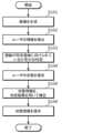
図7は、本実施の形態における車載装置1の処理の例を示すフロー図である。 FIG. 7 is a flow diagram illustrating an example of processing of the in-
ステップS101において、カメラ5は、車両Vの車室S内にいるユーザUが撮影された画像を生成する。 In step S101, the
ステップS102において、視線検出部11は、ステップS101で生成された画像に基づいて、視線検出処理によりユーザUの視線を検出する。 In step S102, the line-of-
ステップS103において、判定部12は、ステップS102で検出された視線が、所定領域に向けられているか否かの判定をする。 In step S103, the
ステップS104において、状態推定部13は、ステップS101で生成された画像に基づいて、ユーザUの状態を推定し、状態情報を生成する。 In step S104, the
ステップS105において、補正部14は、ステップS104で生成された状態情報を、ステップS103での判定の結果を用いて補正する。 In step S105, the
ステップS106において、提示部20は、ステップS105で補正された後の状態情報を提示する。 In step S106, the
図7に示される一連の処理により、車載装置1は、ユーザUの状態を適切に判定することができる。 Through the series of processes shown in FIG. 7, the in-
(実施の形態の変形例)
図8は、本実施の形態の変形例における車載装置1Aの機能構成を示すブロック図である。(Modified example of embodiment)
FIG. 8 is a block diagram showing the functional configuration of the in-
図8に示されるように、車載装置1Aは、カメラ5と、処理部10Aと、提示部20とを備える。カメラ5と提示部20は、上記実施の形態におけるものと同じである。以降において、処理部10Aについて詳しく説明する。 As shown in FIG. 8, the in-
図8に示されるように、処理部10Aは、視線検出部11と、判定部12と、状態推定部13と、補正部14と、調整部15とを備える。視線検出部11と、判定部12と、状態推定部13と、補正部14とは、上記実施の形態におけるものと同じである。 As shown in FIG. 8, the
調整部15は、判定部12が判定に用いる所定領域を調整する機能部である。 The
調整部15は、一例として、提示部20が、表示画面を備える電子ミラーであるルームミラーMである場合に、ルームミラーMによる情報の表示のタイミングを用いて、所定領域を調整することができる。具体的には、調整部15は、提示部20が表示画面に情報を提示したときにカメラ5による撮影により生成された画像から、視線検出部11により得られるユーザUの視線が向けられている領域を含むように、所定領域を調整する。調整部15が所定領域を調整した場合、判定部12は、調整した後の所定領域を用いて判定を行う。なお、上記機能を実行する機能部を、第一調整部ともいう。 For example, when the
また、調整部15は、一例として、車両Vが、当該車両Vの後方に他の車両が近接していることを感知するセンサを備えている場合に、他の車両が近接しているタイミングを用いて、所定領域を調整することができる。具体的には、調整部15は、車両Vの後方に他の車両が近接していることをセンサが感知しているタイミングにおいてカメラ5による撮影により生成された画像から、視線検出部11により得られるユーザUの視線が向けられている領域を含むように、所定領域を調整する。なお、上記機能を実行する機能部を、第二調整部ともいう。上記センサは、例えば、超音波センサ、LiDAR(light detection and ranging)、または、後方カメラである。なお、上記センサは、車両Vに接近する車両に関する情報を、車両を接続するネットワークを介して受信してもよい。 Further, as an example, when the vehicle V is equipped with a sensor that detects that another vehicle is approaching behind the vehicle V, the
なお、調整部15は、車両Vの後方に他の車両が近接していることをセンサが感知している期間を特定し、特定した期間内にカメラ5による複数回の撮影により生成された複数の画像を用いて、所定領域を調整してもよい。 Note that the
以上のように、本実施の形態の車載装置は、ユーザがルームミラーに視線を向けているか否かを適切に判定し、その判定結果を用いて、ユーザの推定される状態を補正することで、ユーザの状態をより適切に判定することができる。特に、車室内の天井の近傍に設置されたカメラを用いるので、ユーザがルームミラーに視線を向けているか否かをより適切に判定することができ、最終的なユーザの状態の判定結果がより適切なものとなる効果がある。このように、車載装置は、ユーザの状態を適切に判定することができる。 As described above, the in-vehicle device of this embodiment appropriately determines whether or not the user is directing his or her gaze toward the rearview mirror, and uses the determination result to correct the estimated state of the user. , the user's condition can be determined more appropriately. In particular, since a camera installed near the ceiling inside the vehicle is used, it is possible to more appropriately determine whether the user is looking at the rearview mirror, and the final determination result of the user's condition is improved. It has the effect of making it appropriate. In this way, the in-vehicle device can appropriately determine the user's condition.
また、車載装置は、ユーザがルームミラーに視線を向けるタイミングの時間間隔が適正であるか否かをさらに判定することで、ユーザの推定される状態を補正し、ユーザの状態をより適切に判定することができる。よって、車載装置は、ユーザの状態をより適切に判定することができる。 In addition, the in-vehicle device further determines whether the time interval between when the user looks at the rearview mirror is appropriate, corrects the user's estimated state, and determines the user's state more appropriately. can do. Therefore, the in-vehicle device can more appropriately determine the user's condition.
また、車載装置は、所定領域を調整したうえで、調整された所定領域を用いた判定を行う。電子ミラーが情報を提示したタイミングにおいて、ユーザが電子ミラーに視線を向けることが想定されるので、そのときのユーザの視線を用いることにより、当該ユーザの体格または姿勢に応じた所定領域が設定されることが可能であり、これにより、ユーザの推定される状態の補正をより適切にすることができる。よって、車載装置は、ユーザの状態をより適切に判定することができる。 Further, the in-vehicle device adjusts the predetermined area and then makes a determination using the adjusted predetermined area. It is assumed that the user turns his/her line of sight to the electronic mirror at the timing when the electronic mirror presents information, so by using the user's line of sight at that time, a predetermined area is set according to the user's physique or posture. This allows the estimated state of the user to be corrected more appropriately. Therefore, the in-vehicle device can more appropriately determine the user's condition.
また、車載装置は、所定領域を調整したうえで、調整された所定領域を用いた判定を行う。車両の後方に他の車両が近接していることをセンサが感知したタイミングにおいて、ユーザが電子ミラーに視線を向けることが想定されるので、そのときのユーザの視線を用いることにより、当該ユーザの体格または姿勢に応じた所定領域が設定されることが可能であり、これにより、ユーザの推定される状態の補正をより適切にすることができる。よって、車載装置は、ユーザの状態をより適切に判定することができる。 Further, the in-vehicle device adjusts the predetermined area and then makes a determination using the adjusted predetermined area. It is assumed that the user turns his/her line of sight to the electronic mirror at the timing when the sensor detects that another vehicle is approaching behind the vehicle, so by using the user's line of sight at that time, the user's A predetermined area can be set according to the physique or posture, and thereby the estimated state of the user can be corrected more appropriately. Therefore, the in-vehicle device can more appropriately determine the user's condition.
また、車載装置は、実際に車両の後方に他の車両が近接している期間に撮影された複数の画像を用いるので、後方に車両が近接していることを認識したユーザがルームミラーに視線を向けて車両の後方を確認する動作をすることを利用して、所定領域の調整をより適切に行うことができる。よって、車載装置は、ユーザの状態をより適切に判定することができる。 In addition, since the in-vehicle device uses multiple images taken during the period when another vehicle is actually close to the rear of the vehicle, the user who recognizes that the vehicle is close to the rear looks in the rearview mirror. Adjustment of a predetermined area can be made more appropriately by using the action of checking the rear of the vehicle by pointing at the vehicle. Therefore, the in-vehicle device can more appropriately determine the user's condition.
なお、上記実施の形態において、各構成要素は、専用のハードウェアで構成されるか、各構成要素に適したソフトウェアプログラムを実行することによって実現されてもよい。各構成要素は、CPUまたはプロセッサなどのプログラム実行部が、ハードディスクまたは半導体メモリなどの記録媒体に記録されたソフトウェアプログラムを読み出して実行することによって実現されてもよい。ここで、上記実施の形態のサーバなどを実現するソフトウェアは、次のようなプログラムである。 Note that in the above embodiments, each component may be configured with dedicated hardware, or may be realized by executing a software program suitable for each component. Each component may be realized by a program execution unit such as a CPU or a processor reading and executing a software program recorded on a recording medium such as a hard disk or a semiconductor memory. Here, the software that implements the server etc. of the above embodiment is the following program.
すなわち、このプログラムは、コンピュータに、車両の車室内の天井の近傍の位置に設置されるカメラにより、前記車室内にいるユーザが撮影された画像を生成し、前記カメラが生成した前記画像に映っている前記ユーザの視線を検出し、検出した前記ユーザの前記視線が、前記車両が備えるルームミラーを含む所定領域に向けられているか否かの判定をし、前記カメラが生成した画像から前記ユーザの状態を推定し、推定した前記状態を示す状態情報を生成し、生成した前記状態情報を、前記判定の結果を用いて補正し、補正した後の前記状態情報を提示する情報処理方法を実行させるプログラムである。 That is, this program causes a computer to generate an image of a user in the vehicle interior taken by a camera installed near the ceiling of the vehicle interior, and to display the image captured by the camera. detects the user's line of sight, determines whether the detected user's line of sight is directed toward a predetermined area including a rearview mirror provided in the vehicle, and detects the user's line of sight based on the image generated by the camera. executing an information processing method of estimating a state of, generating state information indicating the estimated state, correcting the generated state information using the result of the determination, and presenting the corrected state information. This is a program that allows you to
以上、一つまたは複数の態様に係る車載装置などについて、実施の形態に基づいて説明したが、本発明は、この実施の形態に限定されるものではない。本発明の趣旨を逸脱しない限り、当業者が思いつく各種変形を本実施の形態に施したものや、異なる実施の形態における構成要素を組み合わせて構築される形態も、一つまたは複数の態様の範囲内に含まれてもよい。 Although the in-vehicle devices and the like according to one or more aspects have been described above based on the embodiments, the present invention is not limited to these embodiments. Unless departing from the spirit of the present invention, various modifications that can be thought of by those skilled in the art to this embodiment, and embodiments constructed by combining components of different embodiments are within the scope of one or more embodiments. may be included within.
本発明は、自動車の運転手など、車両内のユーザの状態を判定する車載装置に利用可能である。 INDUSTRIAL APPLICATION This invention can be utilized for the vehicle-mounted apparatus which determines the state of the user in a vehicle, such as a driver of a car.
1、1A 車載装置
5 カメラ
6 撮影方向
7 撮影画角
8 視線方向
9A、9B 角度範囲
10、10A 処理部
11 視線検出部
12 判定部
13 状態推定部
14 補正部
15 調整部
20 提示部
M ルームミラー
S 車室
U ユーザ
V 車両1, 1A Vehicle-mounted
Claims (7)
Translated fromJapanese前記カメラが生成した前記画像に映っている前記ユーザの視線を検出する検出部と、
前記検出部が検出した前記ユーザの前記視線が、前記車両が備えるルームミラーを含む所定領域に向けられているか否かの判定をする判定部と、
前記カメラが生成した画像から前記ユーザの状態を推定し、推定した前記状態を示す状態情報を生成する推定部と、
前記推定部が生成した前記状態情報を、前記判定部による判定結果を用いて補正する補正部と、
前記補正部が補正した後の前記状態情報を提示する提示部とを備える
車載装置。A camera installed near the ceiling of a vehicle interior, the camera generating an image of a user in the vehicle interior;
a detection unit that detects the user's line of sight reflected in the image generated by the camera;
a determination unit that determines whether the line of sight of the user detected by the detection unit is directed toward a predetermined area including a rearview mirror provided in the vehicle;
an estimation unit that estimates a state of the user from an image generated by the camera and generates state information indicating the estimated state;
a correction unit that corrects the state information generated by the estimation unit using the determination result by the determination unit;
An in-vehicle device comprising: a presentation section that presents the state information corrected by the correction section.
前記判定部は、
前記判定において、さらに、複数の前記画像を用いて前記検出部が検出した前記ユーザの前記視線の時間的変化から、前記ユーザの視線が適正な時間間隔で前記所定領域に向けられているか否かを判定する
請求項1に記載の車載装置。The camera generates a plurality of images by photographing the user a plurality of times,
The determination unit includes:
In the determination, further, based on the temporal change in the user's line of sight detected by the detection unit using a plurality of the images, whether or not the user's line of sight is directed to the predetermined area at appropriate time intervals. The in-vehicle device according to claim 1.
前記車載装置は、さらに、
前記提示部が前記表示画面に情報を提示したタイミングにおいて前記カメラによる撮影により生成された前記画像から、前記検出部により得られる前記ユーザの視線が向けられている領域を含むように、前記所定領域を調整する第一調整部を備え、
前記判定部は、
前記第一調整部が調整した後の前記所定領域を用いて前記判定をする
請求項1または2に記載の車載装置。The presentation unit includes the room mirror that is an electronic mirror including a display screen,
The in-vehicle device further includes:
The predetermined area is configured such that the predetermined area includes an area where the user's line of sight obtained by the detection unit is directed from the image generated by photography by the camera at the timing when the presentation unit presents information on the display screen. Equipped with a first adjustment section that adjusts the
The determination unit includes:
The in-vehicle device according to claim 1 or 2, wherein the determination is made using the predetermined area adjusted by the first adjustment section.
前記車載装置は、さらに、
前記車両の後方に他の車両が近接していることを前記センサが感知しているタイミングにおいて前記カメラによる撮影により生成された前記画像から、前記検出部により得られる前記ユーザの視線が向けられている領域を含むように、前記所定領域を調整する第二調整部を備え、
前記判定部は、
前記第二調整部が調整した後の前記所定領域を用いて前記判定をする
請求項1~3のいずれか1項に記載の車載装置。The vehicle includes a sensor that detects that another vehicle is close to the rear of the vehicle,
The in-vehicle device further includes:
The user's line of sight obtained by the detection unit is determined from the image generated by the camera at a timing when the sensor senses that another vehicle is approaching behind the vehicle. a second adjustment unit that adjusts the predetermined area to include the area where the predetermined area is located;
The determination unit includes:
The vehicle-mounted device according to any one of claims 1 to 3, wherein the determination is made using the predetermined area adjusted by the second adjustment section.
前記車両の後方に他の車両が近接していることを前記センサが感知している期間を特定し、特定した前記期間内に前記カメラによる複数回の撮影により生成された複数の前記画像を用いて、前記所定領域を調整する
請求項4に記載の車載装置。The second adjustment section is
A period during which the sensor detects that another vehicle is approaching behind the vehicle is specified, and a plurality of images generated by the camera multiple times during the specified period are used. The in-vehicle device according to claim 4, wherein the predetermined area is adjusted by adjusting the predetermined area.
前記カメラが生成した前記画像に映っている前記ユーザの視線を検出し、
検出した前記ユーザの前記視線が、前記車両が備えるルームミラーを含む所定領域に向けられているか否かの判定をし、
前記カメラが生成した画像から前記ユーザの状態を推定し、推定した前記状態を示す状態情報を生成し、
生成した前記状態情報を、前記判定の結果を用いて補正し、
補正した後の前記状態情報を提示する
情報処理方法。Generating an image of a user in the vehicle interior by a camera installed near the ceiling of the vehicle interior;
detecting the user's line of sight in the image generated by the camera;
determining whether the detected line of sight of the user is directed toward a predetermined area including a rearview mirror provided in the vehicle;
estimating the state of the user from an image generated by the camera and generating state information indicating the estimated state;
correcting the generated state information using the result of the determination,
An information processing method that presents the state information after being corrected.
Priority Applications (1)
| Application Number | Priority Date | Filing Date | Title |
|---|---|---|---|
| JP2022030801AJP2023127179A (en) | 2022-03-01 | 2022-03-01 | In-vehicle device, information processing method, and program |
Applications Claiming Priority (1)
| Application Number | Priority Date | Filing Date | Title |
|---|---|---|---|
| JP2022030801AJP2023127179A (en) | 2022-03-01 | 2022-03-01 | In-vehicle device, information processing method, and program |
Publications (1)
| Publication Number | Publication Date |
|---|---|
| JP2023127179Atrue JP2023127179A (en) | 2023-09-13 |
Family
ID=87971458
Family Applications (1)
| Application Number | Title | Priority Date | Filing Date |
|---|---|---|---|
| JP2022030801APendingJP2023127179A (en) | 2022-03-01 | 2022-03-01 | In-vehicle device, information processing method, and program |
Country Status (1)
| Country | Link |
|---|---|
| JP (1) | JP2023127179A (en) |
- 2022
- 2022-03-01JPJP2022030801Apatent/JP2023127179A/enactivePending
Similar Documents
| Publication | Publication Date | Title |
|---|---|---|
| JP6591085B2 (en) | Motion sickness estimation device, motion sickness prevention device, and motion sickness estimation method | |
| US6668221B2 (en) | User discrimination control of vehicle infotainment system | |
| JP5493593B2 (en) | Sleepiness detection apparatus, sleepiness detection method, and program | |
| EP3033999A1 (en) | Apparatus and method for determining the state of a driver | |
| US20140313333A1 (en) | System and method for imaging a driver of a vehicle | |
| JP2008269496A (en) | Occupant information detection system, occupant restraint system and vehicle | |
| JP6776681B2 (en) | Driver status determination device and driver status determination program | |
| JP7290930B2 (en) | Occupant modeling device, occupant modeling method and occupant modeling program | |
| JP2009244959A (en) | Driving support device and driving support method | |
| JP2017027604A (en) | Method and apparatus for estimating line-of-sight direction of vehicle occupant and method and apparatus for determining head motion enhancement parameters specific to vehicle occupant | |
| JP2020048971A (en) | Eyeball information estimation apparatus, eyeball information estimation method, and eyeball information estimation program | |
| JP4319535B2 (en) | Face orientation detection device | |
| JP6689470B1 (en) | Information processing apparatus, program, and information processing method | |
| JP2020086907A (en) | Careless driving determination device | |
| JP4173083B2 (en) | Arousal state determination device and arousal state determination method | |
| CN108058643B (en) | Vehicle rear area image display device and computer-readable medium storing vehicle rear area image display program | |
| JP5082620B2 (en) | Judgment judgment device | |
| JP2023127179A (en) | In-vehicle device, information processing method, and program | |
| JP2007022494A (en) | Angle control device for display unit | |
| JP6673070B2 (en) | Driver state guidance device and driver state guidance program | |
| JP2004322728A (en) | In-vehicle information providing device | |
| WO2022097185A1 (en) | Drowsiness detection device and drowsiness detection method | |
| JP7333895B1 (en) | Motion sickness suppression device and motion sickness suppression method | |
| JP7632629B2 (en) | Start control device and start control program for drive mechanism | |
| JP2023114500A (en) | STATE DETERMINATION DEVICE, STATE DETERMINATION METHOD, AND PROGRAM |
Legal Events
| Date | Code | Title | Description |
|---|---|---|---|
| A711 | Notification of change in applicant | Free format text:JAPANESE INTERMEDIATE CODE: A711 Effective date:20240304 |