JP2023121413A - Optical system for virtual image display device, virtual image display device, and head-mounted display - Google Patents
Optical system for virtual image display device, virtual image display device, and head-mounted displayDownload PDFInfo
- Publication number
- JP2023121413A JP2023121413AJP2022024757AJP2022024757AJP2023121413AJP 2023121413 AJP2023121413 AJP 2023121413AJP 2022024757 AJP2022024757 AJP 2022024757AJP 2022024757 AJP2022024757 AJP 2022024757AJP 2023121413 AJP2023121413 AJP 2023121413A
- Authority
- JP
- Japan
- Prior art keywords
- image display
- display device
- virtual image
- guide member
- light guide
- Prior art date
- Legal status (The legal status is an assumption and is not a legal conclusion. Google has not performed a legal analysis and makes no representation as to the accuracy of the status listed.)
- Pending
Links
Images


Classifications
- G—PHYSICS
- G02—OPTICS
- G02B—OPTICAL ELEMENTS, SYSTEMS OR APPARATUS
- G02B27/00—Optical systems or apparatus not provided for by any of the groups G02B1/00 - G02B26/00, G02B30/00
- G02B27/0025—Optical systems or apparatus not provided for by any of the groups G02B1/00 - G02B26/00, G02B30/00 for optical correction, e.g. distorsion, aberration
- G—PHYSICS
- G02—OPTICS
- G02B—OPTICAL ELEMENTS, SYSTEMS OR APPARATUS
- G02B27/00—Optical systems or apparatus not provided for by any of the groups G02B1/00 - G02B26/00, G02B30/00
- G02B27/01—Head-up displays
- G—PHYSICS
- G02—OPTICS
- G02B—OPTICAL ELEMENTS, SYSTEMS OR APPARATUS
- G02B27/00—Optical systems or apparatus not provided for by any of the groups G02B1/00 - G02B26/00, G02B30/00
- G02B27/01—Head-up displays
- G02B27/0101—Head-up displays characterised by optical features
- G—PHYSICS
- G02—OPTICS
- G02B—OPTICAL ELEMENTS, SYSTEMS OR APPARATUS
- G02B27/00—Optical systems or apparatus not provided for by any of the groups G02B1/00 - G02B26/00, G02B30/00
- G02B27/01—Head-up displays
- G02B27/017—Head mounted
- G02B27/0172—Head mounted characterised by optical features
- G—PHYSICS
- G02—OPTICS
- G02B—OPTICAL ELEMENTS, SYSTEMS OR APPARATUS
- G02B27/00—Optical systems or apparatus not provided for by any of the groups G02B1/00 - G02B26/00, G02B30/00
- G02B27/02—Viewing or reading apparatus
- G—PHYSICS
- G02—OPTICS
- G02B—OPTICAL ELEMENTS, SYSTEMS OR APPARATUS
- G02B27/00—Optical systems or apparatus not provided for by any of the groups G02B1/00 - G02B26/00, G02B30/00
- G02B27/02—Viewing or reading apparatus
- G02B27/022—Viewing apparatus
- G02B27/027—Viewing apparatus comprising magnifying means
- G—PHYSICS
- G02—OPTICS
- G02B—OPTICAL ELEMENTS, SYSTEMS OR APPARATUS
- G02B27/00—Optical systems or apparatus not provided for by any of the groups G02B1/00 - G02B26/00, G02B30/00
- G02B27/09—Beam shaping, e.g. changing the cross-sectional area, not otherwise provided for
- G02B27/0938—Using specific optical elements
- G02B27/0977—Reflective elements
- G02B27/0983—Reflective elements being curved
- G—PHYSICS
- G02—OPTICS
- G02B—OPTICAL ELEMENTS, SYSTEMS OR APPARATUS
- G02B27/00—Optical systems or apparatus not provided for by any of the groups G02B1/00 - G02B26/00, G02B30/00
- G02B27/01—Head-up displays
- G02B27/0101—Head-up displays characterised by optical features
- G02B2027/011—Head-up displays characterised by optical features comprising device for correcting geometrical aberrations, distortion
- G—PHYSICS
- G02—OPTICS
- G02B—OPTICAL ELEMENTS, SYSTEMS OR APPARATUS
- G02B27/00—Optical systems or apparatus not provided for by any of the groups G02B1/00 - G02B26/00, G02B30/00
- G02B27/01—Head-up displays
- G02B27/0101—Head-up displays characterised by optical features
- G02B2027/0123—Head-up displays characterised by optical features comprising devices increasing the field of view
- G02B2027/0125—Field-of-view increase by wavefront division
- G—PHYSICS
- G02—OPTICS
- G02B—OPTICAL ELEMENTS, SYSTEMS OR APPARATUS
- G02B27/00—Optical systems or apparatus not provided for by any of the groups G02B1/00 - G02B26/00, G02B30/00
- G02B27/01—Head-up displays
- G02B27/017—Head mounted
- G02B2027/0178—Eyeglass type
Landscapes
- Physics & Mathematics (AREA)
- General Physics & Mathematics (AREA)
- Optics & Photonics (AREA)
- Lenses (AREA)
Abstract
Description
Translated fromJapanese本発明は、虚像表示装置用光学系、虚像表示装置及びヘッドマウントディスプレイに関する。 The present invention relates to an optical system for a virtual image display device, a virtual image display device and a head mounted display.
2次元の画像を拡大し、拡大された虚像を観察者に観察させるように表示する虚像表示装置が知られている。例えば特許文献1に、この種の虚像表示装置の具体的構成が記載されている。 A virtual image display device is known that enlarges a two-dimensional image and displays the enlarged virtual image so that an observer can observe it. For example,
特許文献1に記載の虚像表示装置は、グラスデバイスであり、画像表示素子がフレーム部に埋設されている。この虚像表示装置は、画像表示素子の各画素から発せられた光(以下「画像光」と記す。)をレンズ内で導光し、導光された画像光を観察者に向けて射出し、射出された画像光を観察者が拡大された虚像として観察できるように構成される。 The virtual image display device described in
特許文献1に記載の虚像表示装置では、コリメート光がレンズ内で導光される。この構成では、導光部材の一例であるレンズの厚さを薄くすることが難しい。 In the virtual image display device described in
本発明は上記の事情に鑑みてなされたものであり、その目的とするところは、画像光を導光する導光部材を薄型化することが可能な虚像表示装置用光学系、このような虚像表示装置用光学系を備える虚像表示装置及びヘッドマウントディスプレイを提供することである。 SUMMARY OF THE INVENTION The present invention has been made in view of the above circumstances, and aims to provide an optical system for a virtual image display device capable of reducing the thickness of a light guide member for guiding image light, and to provide such a virtual image display device. It is an object of the present invention to provide a virtual image display device and a head-mounted display that include an optical system for a display device.
本発明の一実施形態に係る虚像表示装置用光学系は、画像を表示する画像表示素子からの画像光を導光する導光部材と、第1の側から導光部材内を導光される画像光を透過させ、かつ第1の側とは異なる第2の側から導光部材内を導光される画像光を反射させて外部に射出する、部分反射部と、部分反射部を挟んで第1の側とは異なる第2の側に位置し、部分反射部を透過した画像光を部分反射部に向けて反射する反射部と、画像光の中間像を導光部材内に形成する中間像形成部と、を含む。 An optical system for a virtual image display device according to an embodiment of the present invention includes a light guide member that guides image light from an image display element that displays an image, and a light guide member that guides light from a first side through the light guide member. A partial reflection portion that transmits image light and reflects and emits image light guided through the light guide member from a second side different from the first side, with the partial reflection portion interposed therebetween. a reflecting portion positioned on a second side different from the first side and reflecting the image light transmitted through the partial reflecting portion toward the partial reflecting portion; and an intermediate portion forming an intermediate image of the image light within the light guide member and an image forming station.
本発明の一実施形態によれば、画像光を導光する導光部材を薄型化することが可能な虚像表示装置用光学系、このような虚像表示装置用光学系を備える虚像表示装置及びヘッドマウントディスプレイが提供される。 INDUSTRIAL APPLICABILITY According to an embodiment of the present invention, an optical system for a virtual image display device capable of thinning a light guide member for guiding image light, a virtual image display device and a head provided with such an optical system for a virtual image display device. A mounted display is provided.
以下、本発明の一実施形態に係る虚像表示装置用光学系、虚像表示装置及びヘッドマウントディスプレイについて図面を参照しながら説明する。以下の説明において、共通の又は対応する要素については、同一又は類似の符号を付して、重複する説明を適宜簡略又は省略する。 DETAILED DESCRIPTION OF THE INVENTION An optical system for a virtual image display device, a virtual image display device, and a head mounted display according to one embodiment of the present invention will be described below with reference to the drawings. In the following description, common or corresponding elements are denoted by the same or similar reference numerals, and overlapping descriptions are appropriately simplified or omitted.
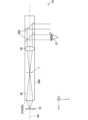
図1は、本発明の一実施形態に係る虚像表示装置を備えるヘッドマウントディスプレイ1の概略図である。本実施形態において、ヘッドマウントディスプレイ1は、例えばメガネ型ウェアラブル端末であるスマートグラスである。スマートグラスは、グラスデバイスやグラスディスプレイと呼ばれてもよい。ヘッドマウントディスプレイ1は、VR(Virtual Reality)グラス、AR(Augmented Reality)グラス、MR(Mixed Reality)グラス、XR(eXtended Reality)グラス等と呼称されるウェアラブル端末であってもよい。 FIG. 1 is a schematic diagram of a head mounted
図1の例では、ヘッドマウントディスプレイ1は、両眼タイプのヘッドマウントディスプレイである。別の実施形態では、ヘッドマウントディスプレイ1は、左右一方の眼に対応する単眼タイプのヘッドマウントディスプレイであってもよい。 In the example of FIG. 1, the head mounted
図1に示されるように、ヘッドマウントディスプレイ1は、フレーム部2及びレンズ部3を備える。レンズ部3は、フレーム部2に嵌め込まれている。レンズ部3は、装用者の左右の眼に対応して一対備えられる。 As shown in FIG. 1, the head mounted
画像を表示する画像表示素子10がフレーム部2に内蔵されている。図1の例では、フレーム部2内の、レンズ部3の上側縁を覆う部分に、画像表示素子10が埋設されている。なお、画像表示素子10の設置位置は、図1に例示される位置に限らない。例えば、フレーム部2内の、レンズ部3の下側縁を覆う部分に、画像表示素子10が埋設されてもよい。 An
画像表示素子10は、虚像として観察すべき画像を表示する素子であり、例示的には、OLED(Organic Light Emitting Diode)アレイ、LD(laser diode)アレイ、LED(Light Emitting Diode)アレイ、MEMS(Micro Electro Mechanical Systems)、DMD(Digital Micromirror Device)等である。 The
以下の説明において、図1中、レンズ部3から装用者の眼に向かう第1の水平方向をz方向とし、z方向と直交する第2の水平方向をx方向とし、x方向とz方向の双方に直交する鉛直方向をy方向とする。互いに直交するx方向、y方向及びz方向は、左手系をなす。なお、方向の呼称は、構成要素の相対的な位置関係を説明するために便宜上用いる呼称であり、絶対的な方向を示すものではない。ヘッドマウントディスプレイ1を装用する装用者の姿勢によっては、例えば、z方向が必ずしも水平方向とは限らず、鉛直方向になることもある。 In the following description, in FIG. 1, the first horizontal direction from the
画像表示素子10の各画素から発せられた光(すなわち画像光)は、画像表示素子10からy方向負側に射出されてレンズ部3内に入射され、レンズ部3内を導光されて、z方向正側に向かって(言い換えると、装用者の各眼に向かって)虚像表示のために射出される。すなわち、左右一対のレンズ部3は、それぞれ、対応する眼を含む領域にアイボックスを形成する。 Light (that is, image light) emitted from each pixel of the
図2は、本発明の一実施形態に係る虚像表示装置1Aの基本的な構成を示す概略構成図である。虚像表示装置1Aは、一例として、ヘッドマウントディスプレイ1に搭載される。 FIG. 2 is a schematic configuration diagram showing the basic configuration of a virtual
なお、本実施形態に係る虚像表示装置1Aは、ヘッドマウントディスプレイに限らず、他の形態の装置にも搭載可能である。一例として、ヘッドアップディスプレイにも搭載することができる。 It should be noted that the virtual
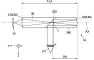
虚像表示装置1Aは、画像表示素子10と、少なくとも導光部材30を含む虚像表示装置用光学系と、を備える。図2の例では、虚像表示装置1Aは、画像表示素子10と虚像表示装置用光学系の一例である導光部材30を備える。なお、図2中、符号EYは装用者の左右一方の眼を示す。 The virtual
詳しくは後述するが、虚像表示装置用光学系は、伝搬光学系、開口絞りa、及び導光部材30とは別の光学部材を更に含む構成としてもよい。 Although details will be described later, the optical system for a virtual image display device may be configured to further include an optical member other than the propagation optical system, the aperture stop a, and the
導光部材30は、画像表示素子10からの画像光を導光する光学部材である。虚像表示装置1Aをヘッドマウントディスプレイ1に搭載した場合、レンズ部3が導光部材30に相当する。 The
導光部材30は、画像表示素子10からの画像光が入射される第1面310(入射面)を有する。導光部材30の内部に、第1面310より入射された画像光を反射光と透過光に分岐する部分反射部320が配置される。 The
部分反射部320は、導光部材30内をy方向負側に導光される画像光(言い換えると、画像表示素子10が位置する第1の側から導光部材30内を導光される画像光)の一部を透過させ、かつ導光部材30内をy方向正側に導光される画像光(言い換えると、第1の側とは異なる第2の側から導光部材30内を導光される画像光)の一部をz方向正側に反射させて、導光部材30の第3面340(射出面)から外部に射出する。 The
後述する数値実施例1~5で示されるように、複数の部分反射部320が導光部材30内に光軸AX方向に間隔dで並んで配置されてもよい。言い換えると、隣接する2つの部分反射部320の光軸AX上の間隔が間隔dであってもよい。なお、本実施形態では、画像表示素子10の有効画素領域の中心から画素配列面に対して垂直方向に射出された光線が通る光路を「光軸AX」と定義する。光軸AXは、虚像表示装置1Aの光軸でもあり、また、虚像表示装置用光学系に含まれる各光学素子(例えば導光部材30)の光軸でもある。 As shown in Numerical Examples 1 to 5 to be described later, a plurality of
複数の部分反射部320により画像光が複数の光束に分岐されることにより、アイボックスが拡大し、また、画角も拡大する。これにより、例えば装用者が虚像表示装置1Aに対して眼EYを動かした場合にも装用者に虚像を視認させやすくなり、また、広い画角をもつ虚像を装用者に視認させることができる。 By splitting the image light into a plurality of light fluxes by the plurality of
上記の間隔dは、適切なアイボックスを確保するため、例えば次式(1)を満たす。 The above distance d satisfies, for example, the following formula (1) in order to secure an appropriate eyebox.
式(1)
0.5mm<d<3.0mmformula (1)
0.5mm<d<3.0mm
間隔dが0.5mm以下になると、例えば、ある部分反射部320で反射された画像光が隣接する部分反射部320でも反射されることに起因する光量ムラ(虚像の輝度ムラ)が発生しやすくなる。間隔dが3.0mm以上になると、間隔dが広すぎることに起因して、例えばアイボックス内の場所によって、虚像が欠けて見えることがある。 If the distance d is 0.5 mm or less, for example, unevenness in the amount of light (unevenness in brightness of the virtual image) due to image light reflected by a certain
複数の部分反射部320が配置される間隔dは等間隔であってもよく、また、等間隔でなくてもよい。 The interval d at which the plurality of
部分反射部320は、画像光が光軸AX(及びz方向正側に向けて射出される第3面340)に対して所定の角度(例えば45度)をなす向きで配置される。部分反射部320は、例えばハーフミラーである。部分反射部320は、PBS(Polarizing Beam Splitter)であってもよい。 The
部分反射部320は、例えば、平面に形成された部分反射面よりなる。部分反射部320を平面で形成することにより、例えば、製造容易性が向上し、また、収差補正の面で有利である。 The
非平面(曲率をもつ面等)の部分反射部320を複数有する場合を考える。この場合、適切に収差が補正された高画質の虚像を表示するためには、隣接する部分反射部320同士を異なる形状に形成する必要がある。さらに、収差を適切に補正するためには、画像光の光路上における、部分反射部320よりも画像表示素子10側に位置する光学系と、それぞれの部分反射部320とで、収差補正を分担する必要がある。その結果、複数の部分反射部320は、それぞれが異なる自由曲面を有する形状とすることが必要となる。そのため、製造容易性を確保することが難しく、また、収差を補正することが難しくなる。 Consider a case in which a plurality of non-planar (surfaces with curvature, etc.)
図2の例では、導光部材30は、一対の光学ブロックよりなる。一方の光学ブロックの傾斜面に、部分反射部320をなす部分反射面が成膜される。部分反射面が成膜された光学ブロックの傾斜面と他方の光学ブロックの傾斜面とを接着剤で接着することにより、導光部材30が完成する。 In the example of FIG. 2, the
部分反射面は、例えば金属材を蒸着することによって形成された蒸着膜よりなる。光学ブロック同士の密着性を向上させるため、光学ブロックの傾斜面にプライマー層を成膜したうえで部分反射面を成膜してもよい。 The partially reflective surface is made of a deposited film formed by depositing a metal material, for example. In order to improve the adhesion between the optical blocks, the partially reflective surface may be formed after forming a primer layer on the inclined surface of the optical block.
導光部材30の各光学ブロックは、例えばプラスチック等の合成樹脂製の成形品である。これにより、導光部材30を軽量化させることができる。導光部材30を軽量化させることにより装用者の鼻にかかる荷重が低減するため、例えばヘッドマウントディスプレイ1を装用者が長時間装用したときの疲労感が軽減される。 Each optical block of the
虚像表示装置1Aは、画像表示素子10からの画像光の中間像Iを導光部材30内に形成する中間像形成部20を含む。 The virtual
図2の例では、導光部材30の第1面310が球面又は非球面で形成されており、画像表示素子10からの画像光の中間像Iを導光部材30内(例えば部分反射部320付近)に形成する中間像形成部20をなしている。第1面310が中間像形成部20を兼ねることにより、虚像表示装置1Aを小型化することができ、また、製造コストを抑えることができる。 In the example of FIG. 2, the
なお、後述する数値実施例1~5で示されるように、虚像表示装置1Aは、画像表示素子10と導光部材30との間の画像光の光路上に、画像表示素子10からの画像光を導光部材30に伝搬する伝搬光学系を含む構成としてもよい。この場合、例えば、この伝搬光学系が中間像形成部20をなす。伝搬光学系に収差補正を負担させることができるため、例えば各種収差を良好に補正することができる。 Note that, as shown in Numerical Examples 1 to 5 to be described later, the virtual
また、後述する数値実施例1~5で示されるように、中間像形成部20をなす伝搬光学系と導光部材30との間の画像光の光路上に開口絞りaが配置されてもよい。開口絞りaによって、画像表示素子10からの画像光を、伝搬光学系で収差補正された画像光に実質的に絞ることができる。別の観点では、伝搬光学系で収差補正されない不要光を開口絞りaでカットすることができる。そのため、例えばフレアの発生が抑えられ、画質の向上につながる。また、開口絞りaの大きさを適切に設定することにより、十分な被写界深度を確保できるとともに解像度が向上する。また、開口絞りaの形状は円形や矩形でもよく、光軸AXに対して垂直方向に複数配置してもよい。複数の小さい絞りを配置することにより、アイボックスを確保しつつ、被写界深度が広い虚像を表示することが可能になる。 Further, as shown in Numerical Examples 1 to 5 described later, an aperture stop a may be arranged on the optical path of the image light between the propagation optical system forming the intermediate
また、伝搬光学系と導光部材30との間に開口絞りaを配置することにより、開口絞りaが後段の光学系(開口絞りaよりも後段の光学系)により結像する位置(すなわち光学系の射出瞳位置に対応する位置)を装用者の眼EYの付近に配置することができる。そのため、装用者は、広い画角範囲の虚像を視認することができる。 Further, by arranging the aperture stop a between the propagation optical system and the
虚像表示装置1Aは、反射部40を含む。反射部40は、部分反射部320を挟んで第1の側(図2の例では、画像表示素子10が位置する側)とは異なる第2の側(図2の例では、第1の側とは反対側)に位置する。虚像表示装置1Aをヘッドマウントディスプレイ1に搭載した場合、反射部40は、レンズ部3の上部に配置された画像表示素子10と対向するレンズ部3の下部に位置する。 The virtual
第1面310より入射されて部分反射部320を透過した画像光は、反射部40まで導光される。反射部40は、反射面を含む構成となっている。この反射面により、反射部40まで導光された画像光が反射され、部分反射部320に向けてz方向正側に導光される。 The image light incident from the
反射部40の反射面は、正のパワーを有する。この反射面は、部分反射部320を介して入射された画像光をコリメート光又は略コリメート光に変換して、部分反射部320に向けて反射する。これにより、コリメート光又は略コリメート光が、導光部材30内をy方向正側に導光されて、部分反射部320にてz方向正側に反射され、導光部材30の第3面340から外部に射出されて、装用者の眼EYに到達する。コリメート光の場合、装用者は、無限遠の虚像を良好に視認することができる。略コリメート光の場合、装用者は、適切な虚像距離(虚像が形成される面と眼EYとの距離)の虚像を良好に視認することができる。虚像距離は、虚像表示装置1Aの用途に適宜変えてもよい。 The reflecting surface of the reflecting
導光部材30は、部分反射部320を挟んで第1面310と対向して位置する第2面330を有する。図2の例では、第2面330が反射面となっており、反射部40をなしている。第2面330が反射部40を兼ねることにより、虚像表示装置1Aを小型化することができ、また、製造コストを抑えることができる。 The
なお、後述する数値実施例4、5で示されるように、虚像表示装置1Aは、導光部材30の後段の光路上に、導光部材30とは別の光学部材を含む構成としてもよい。この場合、例えば、この別の光学部材が上記反射面を含む反射部40をなす。この反射面は、部分反射部320を透過して導光部材30の第2面330より射出された画像光が入射され、入射された画像光をコリメート光又は略コリメート光に変換して、部分反射部320に向けて反射する。これにより、コリメート光又は略コリメート光が、第2面330より導光部材30内に入射されてy方向正側に導光されて、部分反射部320にてz方向正側に反射され、導光部材30の第3面340から外部に射出されて、装用者の眼EYに到達する。ここで、後述の数値実施例4、5で示されるように、上記の反射面と第2面330との間に屈折力をもつ光学面(後述の第1面410)を配置してもよい。このような場合に、第2面330より導光部材30内に入射される画像光は、第2面330、上記光学面(後述の第1面410)、上記反射面(後述の第2面420)の各光学面によってコリメート光又は略コリメート光となるようにしてもよい。すなわち、これらの光学面のパワーにより、第2面330より導光部材30内に入射された時点で画像光がコリメート光又は略コリメート光となるようにしてもよい。 In addition, as shown in Numerical Examples 4 and 5 to be described later, the virtual
上記構成では、別の光学部材よりなる反射部40に収差補正を負担させることができるため、例えば各種収差を良好に補正することができる。また、この場合、第2面330、上記反射面(一例として、後述の第2面420)、第2面330と上記反射面との間に配置される光学面(一例として、後述の第1面410)のそれぞれに、収差補正を分担させることができるので、より適切に収差を補正することができる。 In the above configuration, since the reflecting
本実施形態に係る虚像表示装置1Aでは、画像表示素子10からの画像光の中間像Iが中間像形成部20により導光部材30内に形成される。これにより、導光部材30を薄型化すること(言い換えると、導光部材30のz方向のサイズを小さく抑えること)ができる。これにより、導光部材30を軽量化させることができる。導光部材30を軽量化させることにより装用者の鼻にかかる荷重が低減するため、例えばヘッドマウントディスプレイ1を装用者が長時間装用したときの疲労感が軽減される。 In the virtual
また、画像表示素子10からの画像光の中間像Iを導光部材30内に形成することにより、虚像表示装置用光学系の瞳を装用者の眼EYの付近に配置することができる。そのため、広い画角を確保しつつ広いアイボックスを確保することもできる。 Further, by forming the intermediate image I of the image light from the
なお、本実施形態では、第1面310より導光部材30内に入射されて部分反射部320を透過した画像光を反射部40にて反射し、部分反射部320にてz方向正側に反射して、導光部材30の第3面340から外部に射出する構成を採用する。これは、中間像Iを導光部材30内に形成することによって導光部材30を薄型化する構成の一例にすぎない。 In the present embodiment, the image light that enters the
例えば、図19に、本発明の変形例に係る虚像表示装置1Aの概略構成図を示す。図19に示されるように、中間像Iを中間像形成部20により導光部材30内に形成し、且つ第1面310より導光部材30内に入射された画像光を、導光部材30内に構成されるコリメート光学系50によりコリメート光又は略コリメート光に変換し、変換された画像光を部分反射部320にてz方向正側に反射して、導光部材30の第3面340から外部に射出する構成を採用してもよい。コリメート光学系50は、導光部材30内に屈折率の異なる材質(例えば高屈折率の材料や、中空構造)により構成されたレンズでもよく、また、導光部材30内に形成された回折光学素子でもよい。すなわち、中間像Iを導光部材30内に形成することによって導光部材30を薄型化させる構成であれば、反射部40を構成要件から省いてもよい。この際、部分反射部320を複数備えることにより、アイボックスをより拡大させ、また、画角をより拡大させることができる。 For example, FIG. 19 shows a schematic configuration diagram of a virtual
このように、反射部40を含まず、且つ中間像形成部20、導光部材30及び複数の部分反射部320を含む構成も、本発明の範疇である。 Thus, a configuration that does not include the reflecting
画像表示素子10からの画像光の中間像Iを導光部材30内に形成した場合に導光部材30を薄型化させられる理由を、図3を用いて説明する。 The reason why the thickness of the
図3のA図は、中間像Iの倍率を1倍としたときの、本実施形態に係る虚像表示装置1Aの概略構成図である。A図中、f1は、中間像形成部20の焦点距離を示し、f2は、反射部40の焦点距離を示す。図3のB図は、本実施形態に係る虚像表示装置1Aに対して中間像形成部20を省いた虚像表示装置の概略構成図である。B図中、f3は、反射部40の焦点距離を示す。図3のC図は、本実施形態に係る虚像表示装置1Aに対し、中間像形成部20に代えて、伝搬光学系20’を備えた虚像表示装置の概略構成図である。伝搬光学系20’は、画像表示素子10からの画像光をコリメート光に変換し、このコリメート光を導光部材30に向けて射出する。C図の反射部40は、入射する画像光はコリメートされているので屈折力をもたない反射面(平面)等で構成される。C図では、画角がA図と同じである。A図~C図の各図中、実線の光束は軸上の光束を示し、破線の光束は軸外の光束を示す。A図~C図の各図中、画像表示素子10の位置にある矢印で示される、画像表示素子10による表示画像の大きさは同じである。FIG. 3A is a schematic configuration diagram of the virtual
外界の景色や映像を装用者に見せるためには、画像表示素子10又は中間像形成部20と反射部40(より詳細には、反射面)との間隔を十分に確保する必要がある。A図において、中間像形成部20と反射部40との間隔は、図1のレンズ部3の縦方向(y方向)の幅に対応する。レンズ部3の縦方向の幅は、装用者が外界の景色等を見ることができるように広く設定することが必要なためである。同様にB図において、画像表示素子10と反射部40との間隔が、レンズ部3の縦方向の幅に対応するので、広く設定することが必要である。同様にC図において、伝搬光学系20’と反射部40との間隔がレンズ部3の縦方向の幅に対応するため、同様に広く設定することが必要である。B図において虚像距離を無限遠とする場合、薄型の導光部材30に軸上及び軸外の光束を導光させるため、焦点距離f3を長くする必要がある。具体的には、B図の例における焦点距離f3は、前述の画像表示素子10と反射部40との間隔に対応するように設定される。それにより、画像光は反射部40でコリメートされて、装用者が虚像を視認することができるようになる。前述の通り、焦点距離f3は、レンズ部3の幅に制約される。そのため、焦点距離f3を短くすることができない。そのため、B図の構成では、広い画角を確保することができない。B図の構成において、画角をA図と同等に確保するためには、画像表示素子10を大型化することが必要であり、虚像表示装置そのものが大型化してしまう。C図において虚像距離を無限遠とする場合、A図と同じ画角を確保する必要上(言い換えると、広い画角を形成するために必要な軸外の光束も導光部材30が導光できるように)、導光部材30の厚さを厚くする必要がある。具体的には、C図における伝搬光学系20’は、画像表示素子10からの軸外光線(破線)を導光するために、光軸AX方向に垂直な方向に大きく(図中の上下方向に広く)する必要がある。それに伴い、伝搬光学系20’から射出される画像光を導光部材30が取り込むためには、導光部材30の厚さ(図中の上下方向)を厚くすることが必要である。In order for the wearer to see the scenery and images of the outside world, it is necessary to secure a sufficient distance between the
これに対し、本実施形態に係る虚像表示装置1Aでは、A図に示されるように、反射部40(より詳細には、反射面)により近い導光部材30内に中間像Iを形成することにより、反射部40の焦点距離f2を短くすることができるので、広い画角を確保しつつも導光部材30を薄型化することができる。言い換えると、導光部材30を薄型化した場合でも、導光部材30は、広い画角を形成するために必要な軸外の光束も導光できる。On the other hand, in the virtual
本実施形態に係る虚像表示装置1Aの具体的構成について更に説明する。 A specific configuration of the virtual
虚像表示装置1Aを搭載するヘッドマウントディスプレイ1を適切なサイズで構成するため、虚像表示装置1Aは、中間像Iの倍率をβとしたとき、次式(2)を満たす構成としてもよい。 In order to configure the head mounted
式(2)
0.5<β<2.0formula (2)
0.5<β<2.0
倍率βが0.5倍以下になると、中間像Iが形成される位置より後段の光学素子の合成の焦点距離が短くなりすぎる。そのため、虚像表示装置用光学系の瞳が、装用者の眼EYから離れた、導光部材30寄りの位置に形成される。そのため、広い画角を確保することが難しくなる。倍率βが2.0倍以上になると、導光部材30を薄型に形成することが難しくなる。 If the magnification β is less than 0.5 times, the focal length of the composition of the optical elements located after the position where the intermediate image I is formed becomes too short. Therefore, the pupil of the optical system for a virtual image display device is formed at a position closer to the
適切な虚像距離を得るため、虚像表示装置1Aは、中間像Iから反射部40の反射面までの、光軸AX方向の距離をDAとし、上記反射面の近軸曲率半径をRとしたとき、次式(3)を満たす構成としてもよい。 In order to obtain an appropriate virtual image distance, the virtual
式(3)
―0.8<DA/R<―0.2Formula (3)
-0.8<DA/R<-0.2
値DA/Rが―0.8以下になると、反射部40の反射面のパワーが強くなりすぎて、虚像距離が無限遠より遠くなる。値DA/Rが―0.2以上になると、反射部40の反射面のパワーが弱くなりすぎて、虚像距離が短くなりすぎる。 When the value DA/R is -0.8 or less, the power of the reflecting surface of the reflecting
なお、後述する数値実施例1~3では、中間像Iから、反射面として形成された導光部材30の第2面330までの、光軸AX方向の距離が距離DAである。後述する数値実施例4、5では、中間像Iから、導光部材30とは別の光学部材で構成された反射部40の第2面420(反射面)までの、光軸AX方向の距離が距離DAである。 In Numerical Examples 1 to 3, which will be described later, the distance in the optical axis AX direction from the intermediate image I to the
虚像表示装置1Aを搭載するヘッドマウントディスプレイ1を適切なサイズで構成するため、虚像表示装置1Aは、導光部材30の第1面310から、反射部40の反射面までの、光軸AX方向の距離をTLAとしたとき、次式(4)を満たす構成としてもよい。 In order to configure the head-mounted
式(4)
15mm<TLA<80mmFormula (4)
15mm<TLA<80mm
距離TLAが15mm以下になると、導光部材30の光軸AX方向のサイズが小さくなりすぎて、装用者が装用できる適切なサイズのヘッドマウントディスプレイ1を構成することが難しくなる。距離TLAが80mm以上になると、導光部材30の光軸AX方向のサイズが大きくなりすぎて、装用者が装用できる適切なサイズのヘッドマウントディスプレイ1を構成することが難しくなる。 If the distance TLA is 15 mm or less, the size of the
なお、後述する数値実施例1~3では、導光部材30の第1面310から、反射面として形成された導光部材30の第2面330までの、光軸AX方向の距離が距離TLAである。後述する数値実施例4、5では、導光部材30の第1面310から、導光部材30とは別の光学部材で構成された反射部40の第2面420(反射面)までの、光軸AX方向の距離が距離TLAである。 In Numerical Examples 1 to 3 described later, the distance in the optical axis AX direction from the
次に、虚像表示装置1Aの具体的な数値実施例1~5を示す。 Next, specific numerical examples 1 to 5 of the virtual
数値実施例1~5において画像表示素子10の有効画素領域のサイズは次の通りである。 In Numerical Examples 1 to 5, the size of the effective pixel area of the
《数値実施例1、2》
z方向に2mm、x方向に6mmの矩形状で、対角方向の長さが6.32mm
《数値実施例3》
z方向に1.6mm、x方向に6mmの矩形状で、対角方向の長さが6.21mm
《数値実施例4、5》
z方向に3mm、x方向に6mmの矩形状で、対角方向の長さが6.71mm<<Numerical Examples 1 and 2>>
2 mm in the z direction, 6 mm in the x direction, and a rectangular shape with a diagonal length of 6.32 mm
<<Numerical Example 3>>
1.6 mm in the z direction, 6 mm in the x direction, and a rectangular shape with a diagonal length of 6.21 mm
<<Numerical Examples 4 and 5>>
3 mm in the z direction, 6 mm in the x direction, and a rectangular shape with a diagonal length of 6.71 mm
数値実施例1~5において虚像距離は無限遠である。数値実施例1~5で示される収差図は、焦点距離17mmの理想レンズで結像する場合で計算されている。 In Numerical Examples 1 to 5, the virtual image distance is infinite. The aberration diagrams shown in Numerical Examples 1 to 5 are calculated in the case of imaging with an ideal lens with a focal length of 17 mm.
[数値実施例1]
本発明の数値実施例1に係る虚像表示装置1Aの光学構成は図4に示される。図4に示されるように、数値実施例1に係る虚像表示装置1Aは、画像表示素子10側から順に、画像表示素子10、中間像形成部20の一例である伝搬光学系、開口絞りa、導光部材30を有する。数値実施例1において、中間像形成部20は、光軸AXに対して回転対称な3枚のレンズで構成される。数値実施例1において、平面形状で形成された5つの部分反射部320が導光部材30内に設けられる。[Numerical Example 1]
FIG. 4 shows the optical configuration of a virtual
数値実施例1において、垂直方向(z方向)、水平方向(x方向)、対角方向の画角は、それぞれ、13.9度、40.0度、42.9度である。開口絞りaは、垂直方向(z方向)に1.7mmで水平方向(x方向)に1.7mmの矩形の開口を有する。 In Numerical Example 1, the angles of view in the vertical direction (z direction), horizontal direction (x direction), and diagonal direction are 13.9 degrees, 40.0 degrees, and 42.9 degrees, respectively. The aperture stop a has a rectangular aperture of 1.7 mm in the vertical direction (z-direction) and 1.7 mm in the horizontal direction (x-direction).
数値実施例1に係る虚像表示装置1Aの具体的数値構成は、表1に示される。表1中、R(単位:mm)は光学素子の各面の曲率半径(又は近軸曲率半径)を示し、D(単位:mm)は光軸AX上の光学素子の厚さ又は光学素子の間隔を示し、Ndはd線(波長587.562nm)の屈折率を示し、νdはd線のアッベ数を示す。アッベ数の右欄には、光学素子の材質の商品名及び製造者を記す。 Table 1 shows a specific numerical configuration of the virtual
表1の番号は、画像表示素子10側から順に、画像表示素子10、中間像形成部20、導光部材30の各面に付されたものである。補足すると、表の番号0は、画像表示素子10の画像表示面(画素配列面)を示す。表の番号1~2は、画像表示素子10に備えられるカバーガラスの各面を示す。カバーガラスは、画像表示素子10の画像表示面をカバーするガラス製部材である。各数値実施例の光学構成図において符号10Aで示される要素は、カバーガラスを示す。 The numbers in Table 1 are assigned to the surfaces of the
表の番号3~8は、中間像形成部20をなす各レンズの各レンズ面を示す。表の番号9は、開口絞りaを示す。
表の番号10~12は、導光部材30、部分反射部320を示す。より詳細には、表の番号10、11、12は、それぞれ、導光部材30の第1面310、反射部40をなす第2面330(反射面)、部分反射部320(部分反射面)を示す。
表の番号11の間隔Dの欄の標記Aは、第2面330から、各部分反射部320(部分反射面)までの、光軸AX方向の距離を示す。便宜上、この距離を距離Aと記す。距離Aは、5つの部分反射部320のうち、最も第2面330側の部分反射部320から順に、11mm、13mm、15mm、17mm、19mmである。すなわち、5つの部分反射部320は、2mmの等間隔で配置される。なお、図4では、最も小さい距離A(すなわち11mm)と最も大きい距離A(すなわち19mm)のみ示す。 The mark A in the space D column of number 11 in the table indicates the distance in the optical axis AX direction from the
表の番号13は、導光部材30の第3面340を示す。番号13の間隔Dは、第3面340から装用者の眼EYまでの距離、すなわちアイレリーフを示す。 Number 13 in the table indicates the
[表1]
表1中、「*」印が付された番号の面は、非球面である。表2に、各非球面のデータを示す。表2中、標記Eは、10を基数、Eの右の数字を指数とする累乗を示す。非球面素子における曲率半径Rは、光軸AX上での曲率半径(近軸曲率半径)を示す。非球面形状は、サグ量をZとし、近軸曲率(1/R)をCとし、光軸からの高さをh(単位:mm)とし、円錐係数をKとし、4次以上の偶数次の非球面係数をA4、A6、・・・とした場合に、次式で示される。In Table 1, the numbered surfaces marked with "*" are aspherical surfaces. Table 2 shows the data for each aspherical surface. In Table 2, the label E indicates a power with 10 as the base and the number to the right of E as the exponent. The radius of curvature R of the aspherical element indicates the radius of curvature (paraxial radius of curvature) on the optical axis AX. The aspherical shape has a sag amount of Z, a paraxial curvature (1/R) of C, a height from the optical axis of h (unit: mm), a conic coefficient of K, and an even-order of 4 or higher. are represented by the following equations, where A4 , A6 , . . .
Z=Ch2/{1+√(1-(1+K)C2h2)}+A4・h4+A6・h6+A8・h8+A10・h10Z=Ch2 /{1+√(1-(1+K)C2 h2 )}+A4・h4 +A6・h6 +A8・h8 +A10・h10
なお、表の記載形式は、以降の数値実施例2~5においても同じである。 The description format of the table is the same in Numerical Examples 2 to 5 below.
[表2]
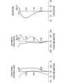
図5は、数値実施例1に係る虚像表示装置1Aの各種収差図(球面収差、非点収差及び歪曲収差)である。図5の球面収差図は、d線、g線(435.834nm)における球面収差を示す。実線はd線における球面収差を示し、破線はg線における球面収差を示す。図5の非点収差図は、d線における非点収差(すなわち、サジタル像面とメリディオナル像面との差)を示す。実線はサジタル方向の収差を示し、破線はメリディオナル方向の収差を示す。球面収差図及び非点収差図の縦軸は像高を示し、横軸は収差量を示す。図5の歪曲収差図の縦軸は像高を示し、横軸はd線における歪曲率を示す。 5A and 5B are various aberration diagrams (spherical aberration, astigmatism, and distortion aberration) of the virtual
図6は、数値実施例1に係る虚像表示装置1Aの横収差図である。横収差図は、図6の上から順に、対角端、水平端、垂直端、中心におけるd線、g線での横収差を示す。実線はd線における横収差を示し、破線はg線における横収差を示す。横収差は、X方向とY方向について測定される。図6左図(上欄に「Y-FAN」が付記された図)は、Y方向における横収差を示し、図6右図(上欄に「X-FAN」が付記された図)は、X方向における横収差を示す。 FIG. 6 is a lateral aberration diagram of the virtual
数値実施例1では、中間像Iを導光部材30内に形成する構成としたことにより、導光部材30を薄型化することができる。また、下記の通り、数値実施例1では、上記式(1)~(4)が全て満たされる。
間隔d : 2.00mm(式(1)参照)
倍率β : 1.43倍(式(2)参照)
値DA/R: -0.50(式(3)参照)
距離TLA: 35.00mm(式(4)参照)In Numerical Example 1, since the intermediate image I is formed in the
Interval d: 2.00 mm (see formula (1))
Magnification β: 1.43 times (see formula (2))
Value DA/R: -0.50 (see formula (3))
Distance TLA: 35.00 mm (see formula (4))
数値実施例1に係る虚像表示装置1Aでは、各種収差が良好に補正されるとともに(図5及び図6参照)、広い画角(例えば対角方向に40度を超える画角)が確保され、良好な像性能が達成される。また、数値実施例1に係る虚像表示装置1Aでは、上記式(1)~(4)を満たすことによる各種効果が奏される。 In the virtual
[数値実施例2]
図7は、本発明の数値実施例2に係る虚像表示装置1Aの光学構成を示す図である。図7に示されるように、数値実施例2に係る虚像表示装置1Aの光学構成は、平面形状で形成された部分反射部320を3つ有する点を除き、数値実施例1に係る虚像表示装置1Aの光学構成と同じである。[Numerical Example 2]
FIG. 7 is a diagram showing an optical configuration of a virtual
数値実施例2において、垂直方向(z方向)、水平方向(x方向)、対角方向の画角は、それぞれ、13.8度、40.0度、42.8度である。開口絞りaは、垂直方向(z方向)に1.8mmで水平方向(x方向)に1.8mmの矩形の開口を有する。 In Numerical Example 2, the angles of view in the vertical direction (z direction), horizontal direction (x direction), and diagonal direction are 13.8 degrees, 40.0 degrees, and 42.8 degrees, respectively. The aperture stop a has a rectangular aperture of 1.8 mm in the vertical direction (z-direction) and 1.8 mm in the horizontal direction (x-direction).
数値実施例2に係る虚像表示装置1Aの具体的数値構成は、表3に示される。数値実施例2において、距離Aは、3つの部分反射部320のうち、最も第2面330側の部分反射部320から順に、13.5mm、15mm、16.5mmである。すなわち、3つの部分反射部320は、1.5mmの等間隔で配置される。数値実施例2の各非球面のデータは、表4に示される。 Table 3 shows a specific numerical configuration of the virtual
[表3]
[表4]
図8は、数値実施例2に係る虚像表示装置1Aの各種収差図(球面収差、非点収差及び歪曲収差)である。図9は、数値実施例2に係る虚像表示装置1Aの横収差図である。 8A and 8B are various aberration diagrams (spherical aberration, astigmatism, and distortion aberration) of the virtual
数値実施例2においても、中間像Iを導光部材30内に形成する構成としたことにより、導光部材30を薄型化することができる。また、下記の通り、数値実施例2においても、上記式(1)~(4)が全て満たされる。
間隔d : 1.50mm(式(1)参照)
倍率β : 1.53倍(式(2)参照)
値DA/R: -0.50(式(3)参照)
距離TLA: 40.00mm(式(4)参照)Also in Numerical Example 2, the intermediate image I is formed in the
Interval d: 1.50 mm (see formula (1))
Magnification β: 1.53 times (see formula (2))
Value DA/R: -0.50 (see formula (3))
Distance TLA: 40.00 mm (see formula (4))
数値実施例2に係る虚像表示装置1Aにおいても、各種収差が良好に補正されるとともに(図8及び図9参照)、広い画角(例えば対角方向に40度を超える画角)が確保され、良好な像性能が達成される。また、数値実施例2に係る虚像表示装置1Aにおいても、上記式(1)~(4)を満たすことによる各種効果が奏される。 Also in the virtual
[数値実施例3]
図10は、本発明の数値実施例3に係る虚像表示装置1Aの光学構成を示す図である。図10に示されるように、数値実施例3に係る虚像表示装置1Aの光学構成は、数値実施例2に係る虚像表示装置1Aの光学構成と同じである。[Numerical Example 3]
FIG. 10 is a diagram showing an optical configuration of a virtual
数値実施例3において、垂直方向(z方向)、水平方向(x方向)、対角方向の画角は、それぞれ、11.2度、40.0度、41.4度である。開口絞りaは、垂直方向(z方向)に1.6mmで水平方向(x方向)に1.6mmの矩形の開口を有する。 In Numerical Example 3, the angles of view in the vertical direction (z direction), horizontal direction (x direction), and diagonal direction are 11.2 degrees, 40.0 degrees, and 41.4 degrees, respectively. The aperture stop a has a rectangular aperture of 1.6 mm in the vertical direction (z-direction) and 1.6 mm in the horizontal direction (x-direction).
数値実施例3に係る虚像表示装置1Aの具体的数値構成は、表5に示される。数値実施例3において、距離Aは、3つの部分反射部320のうち、最も第2面330側の部分反射部320から順に、9mm、10mm、11mmである。すなわち、3つの部分反射部320は、1.0mmの等間隔で配置される。数値実施例3の各非球面のデータは、表6に示される。 Table 5 shows a specific numerical configuration of the virtual
[表5]
[表6]
図11は、数値実施例3に係る虚像表示装置1Aの各種収差図(球面収差、非点収差及び歪曲収差)である。図12は、数値実施例3に係る虚像表示装置1Aの横収差図である。 11A and 11B are various aberration diagrams (spherical aberration, astigmatism, and distortion aberration) of the virtual
数値実施例3においても、中間像Iを導光部材30内に形成する構成としたことにより、導光部材30を薄型化することができる。また、下記の通り、数値実施例3においても、上記式(1)~(4)が全て満たされる。
間隔d : 1.00mm(式(1)参照)
倍率β : 0.96倍(式(2)参照)
値DA/R: -0.50(式(3)参照)
距離TLA: 35.00mm(式(4)参照)Also in Numerical Example 3, the intermediate image I is formed in the
Interval d: 1.00 mm (see formula (1))
Magnification β: 0.96 times (see formula (2))
Value DA/R: -0.50 (see formula (3))
Distance TLA: 35.00 mm (see formula (4))
数値実施例3に係る虚像表示装置1Aにおいても、各種収差が良好に補正されるとともに(図11及び図12参照)、広い画角(例えば対角方向に40度を超える画角)が確保され、良好な像性能が達成される。また、数値実施例3に係る虚像表示装置1Aにおいても、上記式(1)~(4)を満たすことによる各種効果が奏される。 Also in the virtual
[数値実施例4]
図13は、本発明の数値実施例4に係る虚像表示装置1Aの光学構成を示す図である。図13に示されるように、数値実施例4に係る虚像表示装置1Aの光学構成は、中間像形成部20が光軸AXに対して回転対称な4枚のレンズで構成される点、及び導光部材30とは別の光学部材で構成された反射部40を有する点を除き、数値実施例2に係る虚像表示装置1Aの光学構成と同じである。[Numerical Example 4]
FIG. 13 is a diagram showing an optical configuration of a virtual
数値実施例4において、垂直方向(z方向)、水平方向(x方向)、対角方向の画角は、それぞれ、14.8度、30.0度、33.9度である。開口絞りaは、垂直方向(z方向)に2mmで水平方向(x方向)に3mmの矩形の開口を有する。 In Numerical Example 4, the angles of view in the vertical direction (z direction), horizontal direction (x direction), and diagonal direction are 14.8 degrees, 30.0 degrees, and 33.9 degrees, respectively. The aperture stop a has a rectangular aperture of 2 mm in the vertical direction (z-direction) and 3 mm in the horizontal direction (x-direction).
数値実施例4に係る虚像表示装置1Aの具体的数値構成は、表7に示される。補足すると、表の番号3~10は、中間像形成部20をなす各レンズの各レンズ面を示す。表の番号11は、開口絞りaを示す。数値実施例4の各非球面のデータは、表8に示される。 Table 7 shows a specific numerical configuration of the virtual
数値実施例4では、部分反射部320を透過して導光部材30の第2面330より射出された画像光が反射部40の第1面410に入射され、反射部40の第2面420(反射面)にて反射されて第1面410から射出される。この射出光が第2面330より導光部材30内に入射されてy方向正側に導光されて、部分反射部320にてz方向正側に反射され、導光部材30の第3面340から外部に射出されて、装用者の眼EYに到達する。なお、上述で例示として説明したように、第2面330より射出された画像光は、反射部40の第1面410、第2面420(反射面)、第1面410を順に介して、第2面330に入射された時点で、コリメート光又は略コリメート光にされて、第2面330側から部分反射部320に入射される。 In Numerical Example 4, the image light transmitted through the
表の番号12~18は、導光部材30、部分反射部320、反射部40を示す。より詳細には、表の番号12、13、14、15は、それぞれ、導光部材30の第1面310、第2面330、反射部40の第1面410、第2面420を示す。表の番号16は、光路折り返し後の(すなわち第2面420における反射後の光路)に対応する第1面410を示す。 Numbers 12 to 18 in the table indicate the
表の番号17は、光路折り返し後の導光部材30の第2面330を示す。表の番号18は、部分反射部320を示す。数値実施例4において、距離Aは、3つの部分反射部320のうち、最も第2面330側の部分反射部320から順に、11mm、13mm、15mmである。すなわち、3つの部分反射部320は、2mmの等間隔で配置される。 Number 17 in the table indicates the
表の番号19は、導光部材30の第3面340を示す。番号19の間隔Dは、第3面340から装用者の眼EYまでの距離、すなわちアイレリーフを示す。 Number 19 in the table indicates the
[表7]
[表8]
図14は、数値実施例4に係る虚像表示装置1Aの各種収差図(球面収差、非点収差及び歪曲収差)である。図15は、数値実施例4に係る虚像表示装置1Aの横収差図である。 14A and 14B are various aberration diagrams (spherical aberration, astigmatism, and distortion aberration) of the virtual
数値実施例4においても、中間像Iを導光部材30内に形成する構成としたことにより、導光部材30を薄型化することができる。また、下記の通り、数値実施例4においても、上記式(1)~(4)が全て満たされる。
間隔d : 2.00mm(式(1)参照)
倍率β : 1.67倍(式(2)参照)
値DA/R: -0.53(式(3)参照)
距離TLA: 48.50mm(式(4)参照)Also in Numerical Example 4, the intermediate image I is formed in the
Interval d: 2.00 mm (see formula (1))
Magnification β: 1.67 times (see formula (2))
Value DA/R: -0.53 (see formula (3))
Distance TLA: 48.50 mm (see formula (4))
数値実施例4に係る虚像表示装置1Aにおいても、各種収差が良好に補正されるとともに(図14及び図15参照)、広い画角(例えば対角方向に30度を超える画角)が確保され、良好な像性能が達成される。また、数値実施例4に係る虚像表示装置1Aにおいても、上記式(1)~(4)を満たすことによる各種効果が奏される。 Also in the virtual
[数値実施例5]
図16は、本発明の数値実施例5に係る虚像表示装置1Aの光学構成を示す図である。図16に示されるように、数値実施例5に係る虚像表示装置1Aの光学構成は、数値実施例4に係る虚像表示装置1Aの光学構成と同じである。[Numerical Example 5]
FIG. 16 is a diagram showing an optical configuration of a virtual
数値実施例5において、垂直方向(z方向)、水平方向(x方向)、対角方向の画角は、それぞれ、14.9度、30.0度、33.6度である。開口絞りaは、垂直方向(z方向)に2mmで水平方向(x方向)に3mmの矩形の開口を有する。 In Numerical Example 5, the angles of view in the vertical direction (z direction), horizontal direction (x direction), and diagonal direction are 14.9 degrees, 30.0 degrees, and 33.6 degrees, respectively. The aperture stop a has a rectangular aperture of 2 mm in the vertical direction (z-direction) and 3 mm in the horizontal direction (x-direction).
数値実施例5に係る虚像表示装置1Aの具体的数値構成は、表9に示される。数値実施例5において、距離Aは、3つの部分反射部320のうち、最も第2面330側の部分反射部320から順に、10.5mm、13.0mm、15.5mmである。すなわち、3つの部分反射部320は、2.5mmの等間隔で配置される。数値実施例5の各非球面のデータは、表10に示される。 Table 9 shows a specific numerical configuration of the virtual
[表9]
[表10]
図17は、数値実施例5に係る虚像表示装置1Aの各種収差図(球面収差、非点収差及び歪曲収差)である。図18は、数値実施例5に係る虚像表示装置1Aの横収差図である。 17A and 17B are various aberration diagrams (spherical aberration, astigmatism, and distortion aberration) of the virtual
数値実施例5においても、中間像Iを導光部材30内に形成する構成としたことにより、導光部材30を薄型化することができる。また、下記の通り、数値実施例5においても、上記式(1)~(4)が全て満たされる。
間隔d : 2.50mm(式(1)参照)
倍率β : 1.67倍(式(2)参照)
値DA/R: -0.40(式(3)参照)
距離TLA: 48.50mm(式(4)参照)Also in Numerical Example 5, the intermediate image I is formed in the
Interval d: 2.50 mm (see formula (1))
Magnification β: 1.67 times (see formula (2))
Value DA/R: -0.40 (see formula (3))
Distance TLA: 48.50 mm (see formula (4))
数値実施例5に係る虚像表示装置1Aにおいても、各種収差が良好に補正されるとともに(図17及び図18参照)、広い画角(例えば対角方向に30度を超える画角)が確保され、良好な像性能が達成される。また、数値実施例5に係る虚像表示装置1Aにおいても、上記式(1)~(4)を満たすことによる各種効果が奏される。 Also in the virtual
以上が本発明の例示的な実施形態の説明である。本発明の実施形態は、上記に説明したものに限定されず、本発明の技術的思想の範囲において様々な変形が可能である。例えば明細書中に例示的に明示される実施形態等又は自明な実施形態等を適宜組み合わせた内容も本願の実施形態に含まれる。 The foregoing is a description of exemplary embodiments of the present invention. Embodiments of the present invention are not limited to those described above, and various modifications are possible within the scope of the technical idea of the present invention. For example, the embodiments of the present application also include the contents of appropriate combinations of the embodiments and the like exemplarily specified in the specification or the obvious embodiments and the like.
1 :ヘッドマウントディスプレイ
1A :虚像表示装置
2 :フレーム部
3 :レンズ部
10 :画像表示素子
20 :中間像形成部
30 :導光部材
310 :(導光部材30の)第1面
320 :部分反射部
330 :(導光部材30の)第2面
340 :(導光部材30の)第3面
40 :反射部
410 :(反射部40の)第1面
420 :(反射部40の)第2面
a :開口絞り1: Head mounted
Claims (18)
Translated fromJapanese第1の側から前記導光部材内を導光される前記画像光を透過させ、かつ前記第1の側とは異なる第2の側から前記導光部材内を導光される前記画像光を反射させて外部に射出する、部分反射部と、
前記部分反射部を挟んで前記第1の側とは異なる前記第2の側に位置し、前記部分反射部を透過した前記画像光を前記部分反射部に向けて反射する反射部と、
前記画像光の中間像を前記導光部材内に形成する中間像形成部と、を含む、
虚像表示装置用光学系。a light guide member that guides image light from an image display element that displays an image;
The image light guided through the light guide member from a first side is transmitted, and the image light guided through the light guide member is transmitted from a second side different from the first side. a partial reflection part that reflects and emits to the outside;
a reflecting portion located on the second side different from the first side across the partial reflecting portion and reflecting the image light transmitted through the partial reflecting portion toward the partial reflecting portion;
an intermediate image forming unit that forms an intermediate image of the image light within the light guide member;
Optical system for virtual image display.
請求項1に記載の虚像表示装置用光学系。A plurality of the partial reflection units are arranged,
2. The optical system for a virtual image display device according to claim 1.
前記間隔dは、次式
0.5mm<d<3.0mm
を満たす、
請求項2に記載の虚像表示装置用光学系。the plurality of partial reflection portions are arranged side by side at intervals d in the optical axis direction of the optical system for a virtual image display device;
The distance d is determined by the following formula: 0.5 mm<d<3.0 mm
satisfy the
3. The optical system for a virtual image display device according to claim 2.
請求項1から請求項3の何れか一項に記載の虚像表示装置用光学系。The reflecting section includes a reflecting surface having a positive power that reflects the image light transmitted through the partially reflecting section toward the partially reflecting section,
The optical system for a virtual image display device according to any one of claims 1 to 3.
前記導光部材の第2面は、前記反射面であり、前記部分反射部を挟んで前記第1面と対向して位置する、
請求項4に記載の虚像表示装置用光学系。The first surface of the light guide member is an incident surface on which image light from the image display element is incident,
The second surface of the light guide member is the reflective surface and is positioned to face the first surface with the partial reflection portion interposed therebetween.
5. The optical system for a virtual image display device according to claim 4.
前記反射面は、前記部分反射部を透過して前記導光部材より射出された前記画像光が入射され、入射された前記画像光を前記部分反射部に向けて反射する、
請求項4に記載の虚像表示装置用光学系。the reflective portion is made of an optical member different from the light guide member, including the reflective surface;
The image light transmitted through the partial reflection portion and emitted from the light guide member is incident on the reflection surface, and reflects the incident image light toward the partial reflection portion.
5. The optical system for a virtual image display device according to claim 4.
―0.8<DA/R<―0.2
を満たす、
請求項4から請求項6の何れか一項に記載の虚像表示装置用光学系。When the distance in the optical axis direction of the optical system for a virtual image display device from the intermediate image to the reflecting surface is DA, and the paraxial radius of curvature of the reflecting surface is R, the following formula -0.8<DA/ R<-0.2
satisfy the
The optical system for a virtual image display device according to any one of claims 4 to 6.
前記画像表示素子からの画像光が入射される、前記導光部材の入射面から、前記反射面までの、前記虚像表示装置用光学系の光軸方向の距離を、TLAとしたとき、次式
15mm<TLA<80mm
を満たす、
請求項1から請求項7の何れか一項に記載の虚像表示装置用光学系。the reflecting section includes a reflecting surface that reflects the image light transmitted through the partially reflecting section toward the partially reflecting section;
When TLA is the distance in the optical axis direction of the optical system for a virtual image display device from the incident surface of the light guide member on which the image light from the image display element is incident to the reflecting surface, the following equation is obtained. 15mm<TLA<80mm
satisfy the
The optical system for a virtual image display device according to any one of claims 1 to 7.
第1の側から前記導光部材内を導光される前記画像光を透過させ、かつ前記第1の側とは異なる第2の側から前記導光部材内を導光される前記画像光を反射させて外部に射出する、複数の部分反射部と、
前記画像光の中間像を前記導光部材内に形成する中間像形成部と、を含む、
虚像表示装置用光学系。a light guide member that guides image light from an image display element that displays an image;
The image light guided through the light guide member from a first side is transmitted, and the image light guided through the light guide member is transmitted from a second side different from the first side. a plurality of partial reflection parts that reflect and emit to the outside;
an intermediate image forming unit that forms an intermediate image of the image light within the light guide member;
Optical system for virtual image display.
前記間隔dは、次式
0.5mm<d<3.0mm
を満たす、
請求項9に記載の虚像表示装置用光学系。the plurality of partial reflection portions are arranged side by side at intervals d in the optical axis direction of the optical system for a virtual image display device;
The distance d is determined by the following formula: 0.5 mm<d<3.0 mm
satisfy the
The optical system for a virtual image display device according to claim 9.
請求項1から請求項10の何れか一項に記載の虚像表示装置用光学系。wherein the partially reflective part is composed of a partially reflective surface formed on a plane,
The optical system for a virtual image display device according to any one of claims 1 to 10.
0.5<β<2.0
を満たす、
請求項1から請求項11の何れか一項に記載の虚像表示装置用光学系。When the magnification of the intermediate image is β, the following formula 0.5<β<2.0
satisfy the
The optical system for a virtual image display device according to any one of claims 1 to 11.
請求項1から請求項12の何れか一項に記載の虚像表示装置用光学系。further comprising a propagation optical system that propagates image light from the image display element to the light guide member,
The optical system for a virtual image display device according to any one of claims 1 to 12.
請求項13に記載の虚像表示装置用光学系。An aperture stop is arranged on the optical path of the image light between the propagation optical system and the light guide member,
14. The optical system for a virtual image display device according to claim 13.
請求項13又は請求項14に記載の虚像表示装置用光学系。The propagation optical system forms the intermediate image forming section,
The optical system for a virtual image display device according to claim 13 or 14.
請求項1から請求項15の何れか一項に記載の虚像表示装置用光学系。The first surface of the light guide member is an incident surface on which image light from the image display element is incident, and forms the intermediate image forming section.
The optical system for a virtual image display device according to any one of claims 1 to 15.
請求項1から請求項16の何れか一項に記載の虚像表示装置用光学系と、を備える、
虚像表示装置。the image display element;
An optical system for a virtual image display device according to any one of claims 1 to 16,
Virtual image display device.
ヘッドマウントディスプレイ。A virtual image display device according to claim 17,
head mounted display.
Priority Applications (3)
| Application Number | Priority Date | Filing Date | Title |
|---|---|---|---|
| JP2022024757AJP2023121413A (en) | 2022-02-21 | 2022-02-21 | Optical system for virtual image display device, virtual image display device, and head-mounted display |
| US18/107,512US20230266595A1 (en) | 2022-02-21 | 2023-02-09 | Optical system for virtual image display device, virtual image display device, and head-mounted display |
| CN202310130366.XACN116626895A (en) | 2022-02-21 | 2023-02-17 | Optical system for virtual image display device, and head-mounted display |
Applications Claiming Priority (1)
| Application Number | Priority Date | Filing Date | Title |
|---|---|---|---|
| JP2022024757AJP2023121413A (en) | 2022-02-21 | 2022-02-21 | Optical system for virtual image display device, virtual image display device, and head-mounted display |
Publications (1)
| Publication Number | Publication Date |
|---|---|
| JP2023121413Atrue JP2023121413A (en) | 2023-08-31 |
Family
ID=87574180
Family Applications (1)
| Application Number | Title | Priority Date | Filing Date |
|---|---|---|---|
| JP2022024757APendingJP2023121413A (en) | 2022-02-21 | 2022-02-21 | Optical system for virtual image display device, virtual image display device, and head-mounted display |
Country Status (3)
| Country | Link |
|---|---|
| US (1) | US20230266595A1 (en) |
| JP (1) | JP2023121413A (en) |
| CN (1) | CN116626895A (en) |
Cited By (1)
| Publication number | Priority date | Publication date | Assignee | Title |
|---|---|---|---|---|
| WO2024090326A1 (en)* | 2022-10-28 | 2024-05-02 | キヤノン株式会社 | Optical system, display device, and method for manufacturing optical system |
Citations (3)
| Publication number | Priority date | Publication date | Assignee | Title |
|---|---|---|---|---|
| JP2000206446A (en)* | 1999-01-11 | 2000-07-28 | Olympus Optical Co Ltd | Image display device |
| US20130016292A1 (en)* | 2011-07-15 | 2013-01-17 | Google Inc. | Eyepiece for near-to-eye display with multi-reflectors |
| US20160062120A1 (en)* | 2014-08-29 | 2016-03-03 | Google Inc. | Compact architecture for near-to-eye display system |
Family Cites Families (3)
| Publication number | Priority date | Publication date | Assignee | Title |
|---|---|---|---|---|
| US6724354B1 (en)* | 1999-06-21 | 2004-04-20 | The Microoptical Corporation | Illumination systems for eyeglass and facemask display systems |
| US8767305B2 (en)* | 2011-08-02 | 2014-07-01 | Google Inc. | Method and apparatus for a near-to-eye display |
| US9606354B2 (en)* | 2014-07-17 | 2017-03-28 | Google Inc. | Heads-up display with integrated display and imaging system |
- 2022
- 2022-02-21JPJP2022024757Apatent/JP2023121413A/enactivePending
- 2023
- 2023-02-09USUS18/107,512patent/US20230266595A1/enactivePending
- 2023-02-17CNCN202310130366.XApatent/CN116626895A/enactivePending
Patent Citations (3)
| Publication number | Priority date | Publication date | Assignee | Title |
|---|---|---|---|---|
| JP2000206446A (en)* | 1999-01-11 | 2000-07-28 | Olympus Optical Co Ltd | Image display device |
| US20130016292A1 (en)* | 2011-07-15 | 2013-01-17 | Google Inc. | Eyepiece for near-to-eye display with multi-reflectors |
| US20160062120A1 (en)* | 2014-08-29 | 2016-03-03 | Google Inc. | Compact architecture for near-to-eye display system |
Cited By (1)
| Publication number | Priority date | Publication date | Assignee | Title |
|---|---|---|---|---|
| WO2024090326A1 (en)* | 2022-10-28 | 2024-05-02 | キヤノン株式会社 | Optical system, display device, and method for manufacturing optical system |
Also Published As
| Publication number | Publication date |
|---|---|
| CN116626895A (en) | 2023-08-22 |
| US20230266595A1 (en) | 2023-08-24 |
Similar Documents
| Publication | Publication Date | Title |
|---|---|---|
| KR102850187B1 (en) | Optical array for display | |
| JP7077656B2 (en) | Virtual image display device | |
| CN105593745B (en) | Head mounted display optical system and head mounted display | |
| WO2016027442A1 (en) | Light guide device and virtual image display apparatus | |
| KR20190025544A (en) | Eyepiece optics and head mount display | |
| JP2002258208A (en) | Optical element and composite display device utilizing it | |
| JP2005099788A (en) | Hmd device with imaging optics comprising aspheric surface | |
| JP6687885B2 (en) | Virtual image optical system and virtual image display device | |
| US11940623B2 (en) | Observation optical system and display apparatus | |
| JP2003241100A (en) | Eccentric optical system | |
| KR20210153087A (en) | Optical arrangement for display | |
| US12411343B2 (en) | Optical system, virtual image display device, and head-mounted display | |
| US10203502B2 (en) | Image display apparatus | |
| JP2019012259A (en) | Virtual image display apparatus | |
| JP7619176B2 (en) | Propagation optical system, virtual image display device, and head-mounted display | |
| JP2023121413A (en) | Optical system for virtual image display device, virtual image display device, and head-mounted display | |
| JP7330796B2 (en) | Optical system and display device using the same | |
| KR101362873B1 (en) | Lens system for head mounted display | |
| JP6614438B2 (en) | Virtual image optical system and virtual image display device | |
| US12117668B2 (en) | Propagation optical system, virtual image display apparatus, and head-mounted display | |
| JP2001242412A (en) | Virtual image viewing optical system | |
| JP2022095362A (en) | Optical system and display device | |
| US20240085701A1 (en) | Optical system, virtual image display device, and head-mounted display | |
| JP2019132956A (en) | Display device | |
| CN115004084B (en) | Head-mounted display and virtual image imaging lens used in the same |
Legal Events
| Date | Code | Title | Description |
|---|---|---|---|
| RD03 | Notification of appointment of power of attorney | Free format text:JAPANESE INTERMEDIATE CODE: A7423 Effective date:20231025 | |
| A621 | Written request for application examination | Free format text:JAPANESE INTERMEDIATE CODE: A621 Effective date:20241205 | |
| A977 | Report on retrieval | Free format text:JAPANESE INTERMEDIATE CODE: A971007 Effective date:20250827 | |
| A131 | Notification of reasons for refusal | Free format text:JAPANESE INTERMEDIATE CODE: A131 Effective date:20250902 |