Movatterモバイル変換


[0]ホーム

URL:


JP2023121168A - Cooking device - Google Patents

Cooking device
Download PDF

Info

Publication number
JP2023121168A
JP2023121168AJP2022024341AJP2022024341AJP2023121168AJP 2023121168 AJP2023121168 AJP 2023121168AJP 2022024341 AJP2022024341 AJP 2022024341AJP 2022024341 AJP2022024341 AJP 2022024341AJP 2023121168 AJP2023121168 AJP 2023121168A
Authority
JP
Japan
Prior art keywords
pinion gear
rack
door
arm
main body
Prior art date
Legal status (The legal status is an assumption and is not a legal conclusion. Google has not performed a legal analysis and makes no representation as to the accuracy of the status listed.)
Pending
Application number
JP2022024341A
Other languages
Japanese (ja)
Inventor
勝彦 吉田
Katsuhiko Yoshida
Current Assignee (The listed assignees may be inaccurate. Google has not performed a legal analysis and makes no representation or warranty as to the accuracy of the list.)
Twinbird Corp
Original Assignee
Twinbird Corp
Priority date (The priority date is an assumption and is not a legal conclusion. Google has not performed a legal analysis and makes no representation as to the accuracy of the date listed.)
Filing date
Publication date
Application filed by Twinbird CorpfiledCriticalTwinbird Corp
Priority to JP2022024341ApriorityCriticalpatent/JP2023121168A/en
Priority to KR1020230019132Aprioritypatent/KR20230124845A/en
Priority to CN202310128541.1Aprioritypatent/CN116616619A/en
Priority to TW112105813Aprioritypatent/TW202338265A/en
Publication of JP2023121168ApublicationCriticalpatent/JP2023121168A/en
Pendinglegal-statusCriticalCurrent

Links

Images

Classifications

Landscapes

Abstract

Translated fromJapanese

【課題】リンク部材を構成するアームに触れにくくして、載置部をより大きく引き出せる加熱調理装置を提供すること。【解決手段】内部に焼成室15を有する本体2に枢支されてこの正面開口部14を開閉可能な扉3と、扉3の開閉と載置部4の開口部14からの出没を連動させるリンク機構5を有する加熱調理装置としてのオーブントースター1であり、リンク機構5が、前端が扉3に揺動可能に支持されて後側に第一ラック52が形成されるアーム51と、第一ラック52と噛合する第一ピニオンギア53と、第一ピニオンギア53のピッチ円の線速度よりも速い線速度でピッチ円が回動する第二ピニオンギア56と、第二ピニオンギア56と噛合する第二ラック57と、アーム51後側を後方且つ第一ピニオンギア53側に付勢する付勢部材としての引っ張りコイルばね58とを有し、第二ラック57が載置部4に結合される。【選択図】図3An object of the present invention is to provide a heating cooking device that makes it difficult to touch an arm constituting a link member and allows a placing part to be pulled out to a larger extent. [Solution] A door 3 is pivotally supported on a main body 2 having a firing chamber 15 inside and can open and close a front opening 14, and the opening/closing of the door 3 and the coming and going of a placing part 4 from the opening 14 are linked. The toaster oven 1 is a cooking device having a link mechanism 5, and the link mechanism 5 includes an arm 51 whose front end is swingably supported by the door 3 and a first rack 52 is formed on the rear side; A first pinion gear 53 meshes with the rack 52, and a second pinion gear 56 whose pitch circle rotates at a linear speed faster than the linear speed of the pitch circle of the first pinion gear 53 meshes with the second pinion gear 56. It has a second rack 57 and a tension coil spring 58 as a biasing member that biases the rear side of the arm 51 backward and toward the first pinion gear 53, and the second rack 57 is coupled to the mounting section 4. . [Selection diagram] Figure 3

Description

Translated fromJapanese

本発明は、扉を開くことで焼き網等の食品の載置部が本体開口部から突出するオーブントースター等の加熱調理装置に関するものである。 BACKGROUND OF THEINVENTION 1. Field of the Invention The present invention relates to a cooking apparatus, such as a toaster oven, in which a food placing portion such as a gridiron protrudes from an opening of a main body when a door is opened.

従来、この種の加熱調理装置としては、正面に開口部が形成されると共に内部に調理室(本発明の焼成室に相当する)を有する本体部(本発明の本体に相当する)と、この本体部の前記開口部を開閉する開閉扉(本発明の扉に相当する)と、この開閉扉の開閉に連動して調理網(本発明の載置部に相当する)を前後に移動させるリンク機構としてのリンク部材(本発明のアームに相当する)とを有するものが知られている(例えば、特許文献1参照。)。そして、このような加熱調理装置は、前記リンク部材の前端を前記開閉扉の上端近傍に接続することで、この開閉扉を開く動作に連動して、前記調理網を前方に大きく引き出すことができる。 Conventionally, this type of heat cooking apparatus includes a main body portion (corresponding to the main body of the present invention) having an opening formed in the front and a cooking chamber (corresponding to the baking chamber of the present invention) inside; An opening/closing door (corresponding to the door of the present invention) that opens and closes the opening of the main body, and a link that moves the cooking net (corresponding to the placement portion of the present invention) back and forth in conjunction with the opening and closing of the opening/closing door. A mechanism having a link member (corresponding to the arm of the present invention) as a mechanism is known (see, for example, Patent Document 1). In such a heat cooking apparatus, the front end of the link member is connected to the vicinity of the upper end of the opening/closing door, so that the cooking net can be largely pulled out forward in conjunction with the operation of opening the opening/closing door. .

特開2017-116225号公報JP 2017-116225 A

しかしながら、このような加熱調理装置は、前記調理網の引出量を大きくしようとすると、前記リンク部材の前端を前記開閉扉の上端近傍に接続する必要がある。そして、前記開閉扉の解放時、前記リンク部材の前端は前記調理網よりも前方に位置するので、たとえ前記リンク部材が前記調理網よりも下方に位置したとしても、前記リンク部材の前端部に手が触れる虞があった。また、前記調理網の引出量は、前記リンク部材の引出量とこのリンク部材に形成されたリンク長溝の長さの差と略同じであるが、加熱により熱くなった前記本体部に触れずに前記調理網の奥部に被調理物を置くには十分ではなく、より大きく前記調理網を引き出す構造が求められていた。更に、前記調理網を大きく引き出す構造では、この調理網を乗せる器具受台が本体部内空間の前部に位置することになるので、前記調理網を取り外して本体部内空間を清掃しようとすると、前記器具受台が邪魔になり掃除がしにくいという問題があった。 However, in such a heat cooking apparatus, if the amount of pull-out of the cooking net is to be increased, the front end of the link member needs to be connected to the vicinity of the upper end of the opening/closing door. When the opening/closing door is opened, the front end of the link member is positioned forward of the cooking net. I was afraid I might touch it. Further, the pull-out amount of the cooking net is substantially the same as the difference between the pull-out amount of the link member and the length of the link groove formed in the link member. It is not sufficient to place the food to be cooked in the deep part of the cooking net, and a structure for pulling out the cooking net to a greater extent has been desired. Furthermore, in the structure in which the cooking net is pulled out greatly, the utensil receiving base on which the cooking net is placed is located in the front part of the inner space of the main body. There was a problem that the instrument receiving stand was in the way and it was difficult to clean.

本発明は以上の問題点を解決し、リンク部材を構成するアームに触れにくくして、載置部をより大きく引き出せると共に、焼成室内を容易に清掃することができる加熱調理装置を提供することを目的とする。 SUMMARY OF THE INVENTION It is an object of the present invention to provide a heat cooking apparatus which solves the above problems, makes it difficult to touch the arm that constitutes the link member, allows the placement section to be pulled out to a greater extent, and allows the inside of the baking chamber to be easily cleaned. aim.

本発明の請求項1に記載の加熱調理装置は、正面に開口部が形成されると共に内部に焼成室を有する本体と、この本体に枢支されると共に前記開口部を開閉可能な扉と、この扉の開閉に伴って前記開口部から出没する載置部と、前記扉の動きと前記載置部の動きを連動させるリンク機構とを有する加熱調理装置において、前記リンク機構が、前端が前記扉に揺動可能に支持されると共に後側に第一ラックが形成されるアームと、前記第一ラックと噛合する第一ピニオンギアと、この第一ピニオンギアの回動に伴ってこの第一ピニオンギアのピッチ円の線速度よりも速い線速度でピッチ円が回動する第二ピニオンギアと、この第二ピニオンギアと噛合する第二ラックと、前記アームの後側を後方に且つ前記第一ピニオンギア側に付勢する付勢部材とを有し、前記第二ラックが前記載置部に結合されるものである。 The heat cooking apparatus according toclaim 1 of the present invention comprises a main body having an opening formed in the front and having a baking chamber inside, a door pivotally supported by the main body and capable of opening and closing the opening, In a heat cooking apparatus having a placing portion that appears and disappears from the opening as the door is opened and closed, and a link mechanism that interlocks the movement of the door and the motion of the placing portion, the link mechanism an arm swingably supported by the door and formed with a first rack on the rear side; a first pinion gear meshing with the first rack; a second pinion gear whose pitch circle rotates at a linear velocity faster than the linear velocity of the pitch circle of the pinion gear; a second rack that meshes with the second pinion gear; and an urging member that urges the first pinion gear side, and the second rack is coupled to the mounting portion.

また、本発明の請求項2に記載の加熱調理装置は、請求項1において、前記アームに、前記扉が所定角度枢動した際に前記第一ラックが前記第一ピニオンギアと噛合するよう、第一ラックの非形成部が設けられるものである。 Further, in the heat cooking apparatus according toclaim 2 of the present invention, inclaim 1, the arm is provided with a A non-forming portion of the first rack is provided.

また、本発明の請求項3に記載の加熱調理装置は、請求項1において、前後方向に延びる案内部材が前記焼成室の左右両壁にそれぞれ設けられ、前記各案内部材に対し前方から着脱可能な案内受部が前記載置部の左右にそれぞれ設けられると共に、前記付勢部材の付勢力に抗して前記第一ラックが前記第一ピニオンギアから離れる方向に前記アームが揺動可能となるように、前記アームが前記扉に支持されるものである。 According toclaim 3 of the present invention, there is provided a heat cooking apparatus according toclaim 1, wherein guide members extending in the front-rear direction are provided on both left and right walls of the baking chamber, respectively, and can be attached to and detached from the front of the guide members. guide receiving portions are provided on the left and right sides of the placing portion, respectively, and the arm can swing in the direction in which the first rack separates from the first pinion gear against the biasing force of the biasing member. As such, the arm is supported by the door.

更に、また、本発明の請求項4に記載の加熱調理装置は、請求項1において、前記第二ピニオンギアが前記第二ラックの下方に設けられるものである。 Further, according toClaim 4 of the present invention, there is provided the cooking device according toClaim 1, wherein the second pinion gear is provided below the second rack.

本発明の請求項1に記載の加熱調理装置は、以上のように構成することにより、前記扉における前記アームの前端の支持位置を前記扉の枢軸寄りに設けたとしても、前記第一ピニオンギアと第二ピニオンギアの外周部線速度の比を適切にすることで、前記載置部の引出量を、被調理物を安定して載置できる最大限の引出量にすることができる。このため、前記扉の解放時に、前記アームに触れる危険性を減ずることができる。 In the heat cooking apparatus according toclaim 1 of the present invention, with the configuration as described above, even if the support position of the front end of the arm in the door is provided near the pivot axis of the door, the first pinion gear By adjusting the ratio of the linear velocity of the outer peripheral portion of the second pinion gear to that of the second pinion gear, the amount of drawing of the placing portion can be maximized so that the food to be cooked can be stably placed. Therefore, the risk of touching the arm when opening the door can be reduced.

なお、前記アームに、前記扉を所定角度枢動させた際に前記第一ラックが前記第一ピニオンギアと噛合するよう、第一ラックの非形成部を設けることにより、前記扉を開き始めてから所定角度枢動するまでの間、前記載置部が前方に引き出されないので、扉の開放初期にこの扉と載置部が衝突しないようにすることができる。 By providing the arm with a non-formed portion of the first rack so that the first rack engages with the first pinion gear when the door is pivoted by a predetermined angle, the door is opened from the start of opening. Since the mounting portion is not pulled forward until it pivots by a predetermined angle, it is possible to prevent the door from colliding with the mounting portion at the initial stage of opening the door.

また、前後方向に延びる案内部材が前記焼成室の左右両壁にそれぞれ設けられ、前記各案内部材に対し前方から着脱可能な案内受部が前記載置部の左右にそれぞれ設けられると共に、前記付勢部材の付勢力に抗して前記第一ラックが前記第一ピニオンギアから離れる方向に前記アームが揺動可能となるように、前記アームが前記扉に支持されることで、前記載置部を最大突出状態から更に前方に引くと、前記第一ピニオンギアが前記第二ピニオンギア及び第二ラックと連動して回動するが、前記第一ラックと第一ピニオンギアの噛合が一時的に解除されて空回りするので、前記載置部を前記本体から取り外すことができる。このため、前記焼成室内を容易に清掃することができる。 Further, guide members extending in the front-rear direction are provided on the left and right walls of the baking chamber, respectively, and guide receiving portions that can be attached to and detached from the front of the guide members are provided on the left and right sides of the placement portion. The arm is supported by the door so that the arm can swing in a direction in which the first rack moves away from the first pinion gear against the urging force of the biasing member. is further pulled forward from the maximum protruding state, the first pinion gear rotates in conjunction with the second pinion gear and the second rack, but the engagement between the first rack and the first pinion gear temporarily becomes Since it is released and idles, the placement section can be removed from the main body. Therefore, the inside of the firing chamber can be easily cleaned.

更に、前記第二ピニオンギアが前記第二ラックの下方に設けられることにより、前記載置部に被調理物を置く際に前記第二ピニオンギアが邪魔にならないようにすることができる。 Furthermore, since the second pinion gear is provided below the second rack, the second pinion gear does not get in the way when the food to be cooked is placed on the placing portion.

本発明の一実施形態を示す加熱調理装置の斜視図である。BRIEF DESCRIPTION OF THE DRAWINGS It is a perspective view of the heat cooking apparatus which shows one Embodiment of this invention.同、一部を取り外した状態で他の方向から見た斜視図である。It is the perspective view which looked from the other direction in the state which removed one part.同、リンク機構を分解した状態の斜視図である。It is a perspective view of the state where a link mechanism was disassembled equally.同、閉扉状態を外側から見た説明図である。It is the explanatory view which looked at the closed state from the outside similarly.同、扉を角度A開いた状態を外側から見た説明図である。It is the explanatory view which looked at the state where the door was opened by the angle A from the outside.同、扉を角度B開いた状態を外側から見た説明図である。It is the explanatory drawing which looked at the state which opened the angle B of the door similarly from the outside.同、扉を完全に開いた状態を外側から見た説明図である。It is the explanatory drawing which looked at the state which opened the door completely from the outside.同、閉扉状態を焼成室側から見た説明図である。It is an explanatory view of the closed state of the same as seen from the baking chamber side.同、扉を角度A開いた状態を焼成室側から見た説明図である。It is an explanatory view of the state in which the door is opened at an angle A as viewed from the firing chamber side.同、扉を角度B開いた状態を焼成室側から見た説明図である。It is an explanatory view of the state in which the door is opened at an angle B as viewed from the firing chamber side.同、扉を完全に開いた状態を焼成室側から見た説明図である。It is the same explanatory drawing which looked at the state which opened the door completely from the baking chamber side.

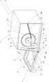
以下、本発明の実施形態について、図1乃至図11に基づいて説明する。1は本発明の加熱調理装置としてのオーブントースターである。このオーブントースター1は、本体2と、扉3と、載置部4と、リンク機構5とを有して構成される。 An embodiment of the present invention will be described below with reference to FIGS. 1 to 11. FIG. 1 is an oven toaster as a heat cooking apparatus of the present invention. Thisoven toaster 1 is configured by having amain body 2 , adoor 3 , a placingsection 4 and alink mechanism 5 .

前記本体2は、内壁部11と外壁部12と前壁部13とを有して構成される。前記内壁部11は正面側に開口部14を有する箱状に形成されると共に、右側壁11Rと左側壁11Lとを有する。そして、この内壁部11内に焼成室15が形成される。また、前記右側壁11R及び左側壁11Lの内面側には、それぞれ案内部材16R,16Lが、同じ高さに且つ前後方向に水平に取り付けられる。これらの案内部材16R,16Lは、それぞれ長さ方向に溝部17R,17Lが形成されると共に、これらの溝部17R,17Lが互いに対向する。また、前記溝部17Rと溝部17Lは、水平で且つ平行に設けられる。従って、前記各溝部17R,17Lの底部同士の間隔は、前記右側壁11Rと左側壁11Lとの間隔よりも僅かに狭い。なお、前記溝部17R,17Lの前端部には、前方ほど前記溝部17R,17Lの間隔が広くなった誘い込み部18R,18Lが形成される。この誘い込み部18R,18Lを除き、前記溝部17R,17Lの幅は一定である。また、前記溝部17R,17Lの後端部には、前記溝部17R,17Lの後端を規定する端壁19が形成される。更に、前記右側壁11Rの前側で且つ前記案内部材16Rの下方には、図示しない軸受孔が形成される。なお、前記外壁部12は、前記内壁部11を外側から覆うものであり、この内壁部11と同様に正面側が開放する。また、前記前壁部13は、前記内壁部11の正面開口部14と前記外壁部12の開放した正面側を繋ぐように設けられる。また、前記前壁部の右側には、前記リンク機構5の後述するアーム51が通される上下方向に細長い貫通溝20が形成される。更に、前記本体2の正面側下方の左右には、それぞれ本体側軸受部21R,21Lが設けられる。 Themain body 2 includes aninner wall portion 11 , anouter wall portion 12 and afront wall portion 13 . Theinner wall portion 11 is formed in a box shape having anopening 14 on the front side, and has aright side wall 11R and aleft side wall 11L. Abaking chamber 15 is formed in theinner wall portion 11 . Further,guide members 16R and 16L are attached horizontally at the same height to the inner surfaces of theright side wall 11R and theleft side wall 11L, respectively. Theseguide members 16R and 16L are formed withgrooves 17R and 17L in the longitudinal direction, respectively, and thesegrooves 17R and 17L face each other. Further, thegroove portion 17R and thegroove portion 17L are provided horizontally and in parallel. Therefore, the distance between the bottoms of thegrooves 17R and 17L is slightly narrower than the distance between theright side wall 11R and theleft side wall 11L. At the front ends of thegrooves 17R and 17L, guidingportions 18R and 18L are formed so that the distance between thegrooves 17R and 17L increases toward the front. The widths of thegrooves 17R and 17L are constant except for the guidingportions 18R and 18L. Further,end walls 19 are formed at the rear ends of thegrooves 17R and 17L to define the rear ends of thegrooves 17R and 17L. Further, a bearing hole (not shown) is formed on the front side of theright side wall 11R and below theguide member 16R. Theouter wall portion 12 covers theinner wall portion 11 from the outside, and the front side is opened like theinner wall portion 11 . Further, thefront wall portion 13 is provided so as to connect thefront opening portion 14 of theinner wall portion 11 and the open front side of theouter wall portion 12 . Further, on the right side of the front wall portion, a vertically elongated throughgroove 20 is formed through which anarm 51 of thelink mechanism 5, which will be described later, is passed. Furthermore, main bodyside bearing portions 21R and 21L are provided on the right and left sides of the lower front side of themain body 2, respectively.

前記扉3は、扉本体31と、この扉本体31の上部に設けられたハンドル32と、前記扉本体31の下部に設けられた扉側軸受部33R,33Lと、前記扉本体31の右側で且つ焼成室15側に設けられたアーム軸受部34とを有して構成される。そして、前記扉側軸受部33R,33Lは、前記本体側軸受部21R,21Lに対応して設けられ、枢軸35R,35Lによって枢動可能に接続される。これによって、前記扉3は前記本体2に対し枢支される。 Thedoor 3 includes a doormain body 31, ahandle 32 provided on the upper part of the doormain body 31, door-side bearings 33R and 33L provided on the lower part of the doormain body 31, and a right side of the doormain body 31. and anarm bearing portion 34 provided on thefiring chamber 15 side. The doorside bearing portions 33R and 33L are provided corresponding to the main bodyside bearing portions 21R and 21L, and are pivotally connected bypivots 35R and 35L. Thedoor 3 is thereby pivotally supported with respect to thebody 2 .

前記載置部4は、載置部本体41と、この載置部本体41の上方に着脱可能に載置される焼き網42とを有して構成される。前記載置部本体41は、金属線材によって略方形状に形成されると共に、この載置部本体41の奥側に、左右にそれぞれ突出する案内受部43R,43Lが設けられる。これらの案内受部43R,43Lの上下方向寸法は、前記案内部材16R,16Lに形成された溝部17R,17Lの上下方向幅よりもやや小さい。また、前記案内部材43Rの右端と前記案内部材43Lの左端との間隔は、前記各溝部17R,17Lの底部同士の間隔よりもやや小さく、且つ、前記溝部17R,17Lから下方に外れない程度の寸法に形成される。即ち、前記案内部材43Rの右端と前記案内部材43Lの左端との間隔は、右側壁11Rと左側壁11Lの間隔、換言すれば前記開口部14の幅よりも小さい。更に、前記載置部本体41の右側端部の下部には、前記リンク機構5の後述する第二ラック57が前後方向に延びるように結合される。 Themounting section 4 includes a mounting sectionmain body 41 and agridiron 42 detachably mounted on the mounting sectionmain body 41 . The mounting portionmain body 41 is formed of a metal wire in a substantially rectangular shape, and is provided withguide receiving portions 43R and 43L projecting to the left and right on the inner side of the mounting portionmain body 41, respectively. The vertical dimension of theseguide receiving portions 43R and 43L is slightly smaller than the vertical width of thegroove portions 17R and 17L formed in theguide members 16R and 16L. The distance between the right end of theguide member 43R and the left end of theguide member 43L is slightly smaller than the distance between the bottoms of thegrooves 17R and 17L, and is such that it does not come off downward from thegrooves 17R and 17L. Formed to size. That is, the distance between the right end of theguide member 43R and the left end of theguide member 43L is smaller than the distance between theright side wall 11R and theleft side wall 11L, in other words, the width of the opening . Furthermore, asecond rack 57 of thelink mechanism 5, which will be described later, is coupled to the lower portion of the right end portion of the mounting portionmain body 41 so as to extend in the front-rear direction.

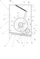
前記リンク機構5は、第一ラック52が形成されたアーム51と、第一ピニオンギア53と、大径ギア54と、小径ギア55と、第二ピニオンギア56と、第二ラック57と、付勢部材としての引っ張りコイルばね58と、ストッパー59とを有して構成される。前記アーム51と、第一ピニオンギア53と、大径ギア54と、小径ギア55と、引っ張りコイルばね58と、ストッパー59は、前記右側壁11Rの外面側に設けられる。一方、前記第二ピニオンギア56は、前記右側壁11Rの内面側に設けられる。更に、前記第二ラック57は、前述したように、前記焼成室15内に設けられる前記載置部4を構成する載置部本体41に結合される。 Thelink mechanism 5 includes anarm 51 formed with afirst rack 52, afirst pinion gear 53, a large-diameter gear 54, a small-diameter gear 55, asecond pinion gear 56, asecond rack 57, and a It is composed of atension coil spring 58 as a force member and astopper 59 . Thearm 51, thefirst pinion gear 53, the large-diameter gear 54, the small-diameter gear 55, thetension coil spring 58, and thestopper 59 are provided on the outer surface side of theright side wall 11R. On the other hand, thesecond pinion gear 56 is provided on the inner surface side of theright side wall 11R. Further, thesecond rack 57 is coupled to the placement sectionmain body 41 that constitutes theplacement section 4 provided in the firingchamber 15, as described above.

前記アーム51は、その前端部に軸受孔60が形成されると共に、その後端部に引掛孔61が形成される。そして、前記アーム51の軸受孔60と前記扉3のアーム軸受部34とを揺動軸62を用いて接続することで、前記アーム51は前記扉3に対し揺動可能に支持される。一方、前記アーム51の引掛孔61には、前記引っ張りコイルばね58の一端側のフック58Aが引っ掛けられる。そして、前記引っ張りコイルばね58の他端側のフック58Bは、前記本体2の後部上方寄りに引っ掛けられる。これによって、前記アーム51の後端部は、後方斜め上に付勢される。また、前記アーム51の上辺部の後側には、前記第一ラック52が形成される。なお、前記アーム51の上辺部において、前端部から前記第一ラック52までの間は、前記第一ラック52の非形成部63である。更に、前記アーム51の下辺部の中央部近傍には、切欠部64が形成される。この切欠部64は、その一端側縁64Aが前記アーム51の長さ方向に対し斜めに切り欠かれ、他端側縁64Bが前記アーム51の長さ方向に対し略垂直に切り欠かれる。そして、前記他端側縁64Bが前記ストッパー59と当接することで、前記扉3の開放角度が角度Cに制限される。 Thearm 51 has abearing hole 60 formed at its front end and a hookinghole 61 formed at its rear end. By connecting the bearinghole 60 of thearm 51 and thearm bearing portion 34 of thedoor 3 using aswing shaft 62, thearm 51 is supported swingably with respect to thedoor 3. As shown in FIG. On the other hand, thehook 58A on the one end side of thetension coil spring 58 is hooked in thehook hole 61 of thearm 51. As shown in FIG. Ahook 58B on the other end side of thetension coil spring 58 is hooked on the upper rear portion of themain body 2 . As a result, the rear end of thearm 51 is urged upward and rearward. Also, thefirst rack 52 is formed on the rear side of the upper side of thearm 51 . In addition, in the upper side portion of thearm 51 , anon-forming portion 63 of thefirst rack 52 is formed between the front end portion and thefirst rack 52 . Furthermore, anotch 64 is formed near the center of the lower side of thearm 51 . Thenotch 64 has oneside edge 64A cut obliquely to the length direction of thearm 51 and theother side edge 64B cut substantially perpendicular to the length direction of thearm 51. As shown in FIG. Then, the opening angle of thedoor 3 is limited to the angle C by the contact of the otherend side edge 64B with thestopper 59. As shown in FIG.

前記第一ピニオンギア53及び大径ギア54は、同軸に且つ一体に回動するように、前記右側壁11Rの外面側に設けられた軸部65に取り付けられる。なお、前記第一ピニオンギア53と大径ギア54は、一体に形成しても良い。そして、前記第一ピニオンギア53は、前記アーム51の上方に位置する。従って、このアーム51の後端側が前記引っ張りコイルばね58によって上方に付勢されることで、前記アーム51が前記第一ピニオンギア53に押し付けられる。また、前記第一ピニオンギア53の軸方向両側には、この第一ピニオンギア53よりも大径な一対の案内円盤66,66が設けられる。そして、これらの案内円盤66,66間に前記アーム51を位置させることで、前記第一ラック52と第一ピニオンギア53が位置ズレしないようにすることができる。なお、前記第一ラック52と第一ピニオンギア53は、前記扉3を開く動作により噛合する。 Thefirst pinion gear 53 and the large-diameter gear 54 are attached to ashaft portion 65 provided on the outer surface side of theright side wall 11R so as to rotate coaxially and integrally. Thefirst pinion gear 53 and the large-diameter gear 54 may be integrally formed. Thefirst pinion gear 53 is positioned above thearm 51 . Therefore, thearm 51 is pressed against thefirst pinion gear 53 by urging the rear end side of thearm 51 upward by thetension coil spring 58 . A pair ofguide discs 66 , 66 having a larger diameter than thefirst pinion gear 53 are provided on both sides of thefirst pinion gear 53 in the axial direction. By positioning thearm 51 between theseguide discs 66, 66, thefirst rack 52 and thefirst pinion gear 53 can be prevented from being displaced. Thefirst rack 52 and thefirst pinion gear 53 mesh with each other when thedoor 3 is opened.

前記小径ギア55は、前記大径ギア54と常時噛合すると共に、この大径ギア54よりも小径に形成される。即ち、前記大径ギア54と小径ギア55とで増速機構が構成される。また、前記小径ギア55の軸方向両側には、この小径ギア55よりも大径な一対の案内円盤67,67が設けられる。そして、これらの案内円盤67,67間に前記大径ギア54を位置させることで、前記大径ギア54と小径ギア55が位置ズレしないようにすることができる。また、前記小径ギア55は、前述した図示しない軸受孔に固定された回動軸68の外側端部に固定される。 The small-diameter gear 55 is always meshed with the large-diameter gear 54 and has a diameter smaller than that of the large-diameter gear 54 . That is, the large-diameter gear 54 and the small-diameter gear 55 constitute a speed increasing mechanism. A pair ofguide discs 67 , 67 having a larger diameter than the small-diameter gear 55 are provided on both sides of the small-diameter gear 55 in the axial direction. By positioning the large-diameter gear 54 between theseguide discs 67, 67, the large-diameter gear 54 and the small-diameter gear 55 can be prevented from being displaced. The small-diameter gear 55 is fixed to the outer end of therotary shaft 68 fixed to the bearing hole (not shown).

前記第二ピニオンギア56は、前記回動軸68の内側端部に固定される。これによって、前記第二ピニオンギア56は、前記小径ギア55と同軸に且つ一体に回動するように構成される。また、前記第二ピニオンギア56は、前記第二ラック57と常時噛合する。更に、前記第二ピニオンギア56の軸方向両側には、この第二ピニオンギア56よりも大径な一対の案内円盤69,69が設けられる。そして、これらの案内円盤69,69間に前記第二ラック57を位置させることで、前記第二ラック57と第二ピニオンギア56が位置ズレしないようにすることができる。 Thesecond pinion gear 56 is fixed to the inner end of thepivot shaft 68 . Thereby, thesecond pinion gear 56 is configured to rotate coaxially and integrally with thesmall diameter gear 55 . Also, thesecond pinion gear 56 is always meshed with thesecond rack 57 . Furthermore, a pair ofguide discs 69, 69 having a larger diameter than thesecond pinion gear 56 are provided on both sides of thesecond pinion gear 56 in the axial direction. By positioning thesecond rack 57 between theseguide discs 69, 69, thesecond rack 57 and thesecond pinion gear 56 can be prevented from being displaced.

前記第一ピニオンギア53が、そのピッチ円における周長方向に回動した距離Lと、前記第二ピニオンギア56が、そのピッチ円における周長方向に回動した距離Mの比、即ち変速比Gは、前記第一ピニオンギア53のピッチ円の半径をR1、前記大径ギア54のピッチ円の半径をR2、前記小径ギア55のピッチ円の半径をR3、前記第二ピニオンギア56のピッチ円の半径をR4とすると、以下の式で表される。なお、計算を単純化するために、各ギア間のバックラッシュは考慮しないものとする。
G=(R2/R1)×(R4/R3)
なお、本実施形態では、各ギアのピッチが等しいので、歯数の比で表すことができる。即ち、変速比Gは、前記第一ピニオンギア53の歯数をT1、前記大径ギア54の歯数をT2、前記小径ギア55の歯数をT3、前記第二ピニオンギア56の歯数をT4とすると、以下の式で表される。
G=(T2/T1)×(T4/T3)
そして、本実施形態では、図4乃至図11に示されるように、T1=T3=T4=26である。また、前記アーム51に隠れる部分があるが、T2=90である。従って、本実施形態では、変速比G≒3.46となる。これは、前記第二ピニオンギア56が前記第一ピニオンギア53の約3.46倍の線速度で回動することを意味する。また、前記第一ピニオンギア53が、そのピッチ円における周長方向に距離L回動すると、前記第二ピニオンギア56が、そのピッチ円の周長方向に距離約3.46L回動することを意味する。
The ratio of the distance L by which thefirst pinion gear 53 rotates in the circumferential direction of its pitch circle to the distance M by which thesecond pinion gear 56 rotates in the circumferential direction of its pitch circle, that is, the gear ratio G is R1 for the pitch circle radius of thefirst pinion gear 53, R2 for the pitch circle radius for thelarge diameter gear 54, R3 for the pitch circle radius for thesmall diameter gear 55, and R3 for the pitch circle of thesecond pinion gear 56. Assuming that the radius of the circle is R4, it is represented by the following formula. To simplify the calculation, backlash between gears is not taken into account.
G=(R2/R1)×(R4/R3)
In this embodiment, since the pitches of the gears are equal, it can be represented by the ratio of the number of teeth. That is, the gear ratio G is defined by T1 for the number of teeth of thefirst pinion gear 53, T2 for the number of teeth for thelarge diameter gear 54, T3 for the number of teeth for thesmall diameter gear 55, and T3 for the number of teeth of thesecond pinion gear 56. T4 is represented by the following equation.
G=(T2/T1)×(T4/T3)
In this embodiment, T1=T3=T4=26, as shown in FIGS. Also, there is a portion hidden by thearm 51, and T2=90. Therefore, in this embodiment, the gear ratio G≈3.46. This means that thesecond pinion gear 56 rotates at a linear velocity approximately 3.46 times that of thefirst pinion gear 53 . Further, when thefirst pinion gear 53 rotates in the circumferential direction of the pitch circle by a distance L, thesecond pinion gear 56 rotates in the circumferential direction of the pitch circle by a distance of about 3.46L. means.

なお、本実施形態において、説明の簡略化のため、前記オーブントースター1に設けられるヒータ、操作部等についての説明は省略する。 In addition, in this embodiment, for the sake of simplification of explanation, the explanation of the heater, operation part, etc. provided in thetoaster oven 1 will be omitted.

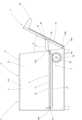
次に、本実施形態の作用について説明する。図4及び図8の初期状態では、前記第一ラック52と第一ピニオンギア53は噛合しておらず、この第一ピニオンギア53の歯は前記第一ラック52の非形成部63に当接している。この状態から使用者は、前記ハンドル32を把持し、前方に引く。これによって、前記扉3が前記枢軸35R,35Lを中心に枢動する。そして、前記扉3の枢動に伴って、前記リンク機構5のアーム51も前方に引かれる。この際、前記アーム51は、前記揺動軸62を中心に揺動する。また、前述したように、前記アーム51の後端側は前記引っ張りコイルばね58によって後上方に付勢されているので、前記アーム51は前記第一ピニオンギア53の歯に押し付けられ続ける。更に、前記案内円盤66,66によって、前記アーム51が前記第一ピニオンギア53の歯から外れるのを防止することができる。そして、前記第一ピニオンギア53の歯は、前記扉3が角度A枢動して図5及び図9の状態になるまで、前記第一ラック52と噛合せずに、前記引っ張りコイルばね58の付勢力によって前記非形成部63に当接し続ける。即ち、前記第一ピニオンギア53、大径ギア54、小径ギア55及び第二ピニオンギア56は、前記扉3が角度A枢動するまで回動しない。従って、前記第二ラック57が結合された前記載置部4の載置部本体41は、前記扉3が角度A枢動するまで前方に移動しない。そして、前記扉3が角度A枢動することで、図5に示すように、前記第一ラック52と第一ピニオンギア53は噛合する。 Next, the operation of this embodiment will be described. 4 and 8, thefirst rack 52 and thefirst pinion gear 53 are not meshed with each other, and the teeth of thefirst pinion gear 53 are in contact with thenon-formed portion 63 of thefirst rack 52. ing. From this state, the user grips thehandle 32 and pulls it forward. As a result, thedoor 3 pivots around thepivots 35R and 35L. As thedoor 3 pivots, thearm 51 of thelink mechanism 5 is also pulled forward. At this time, thearm 51 swings around theswing shaft 62 . Further, as described above, the rear end side of thearm 51 is urged rearward and upward by thetension coil spring 58 , so thearm 51 continues to be pressed against the teeth of thefirst pinion gear 53 . Further, theguide discs 66, 66 prevent thearm 51 from coming off the teeth of thefirst pinion gear 53. Then, the teeth of thefirst pinion gear 53 do not mesh with thefirst rack 52 until thedoor 3 is pivoted by an angle A to the state shown in FIGS. It continues to abut against thenon-formed portion 63 due to the urging force. That is, thefirst pinion gear 53, thelarge diameter gear 54, thesmall diameter gear 55 and thesecond pinion gear 56 do not rotate until thedoor 3 pivots by the angle A. Therefore, the mounting sectionmain body 41 of the mountingsection 4 to which thesecond rack 57 is coupled does not move forward until thedoor 3 pivots by an angle A. As shown in FIG. When thedoor 3 is pivoted by an angle A, thefirst rack 52 and thefirst pinion gear 53 are meshed as shown in FIG.

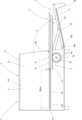
図5及び図9の状態から更に前記扉3を前方に引いて、この扉3を前記枢軸35R,35Lを中心に枢動させると、前記第一ラック52と噛合した前記第一ピニオンギア53は、前記第一ラック52の前方への移動に伴って回動する。そして、この第一ピニオンギア53の回動に伴って、前記大径ギア54がこの第一ピニオンギア53と同じ角速度で回動する。なお、前記大径ギア54のピッチ円における周長方向に回動する距離は、前記第一ピニオンギア53におけるそれよりも長い。また、前記大径ギア54と噛合する前記小径ギア55は、そのピッチ円における周長方向に、前記大径ギア54と同じ距離回動する。更に、前記第二ピニオンギア56は、前記小径ギア55とピッチ円の半径及び歯数が同じであるから、そのピッチ円における周長方向に、前記大径ギア54及び小径ギア55と同じ距離回動する。そして、前述したように、変速比Gが約3.46であるため、前記第二ピニオンギア56のピッチ円における周長方向に回動する距離は、前記第一ピニオンギア53のそれの約3.46倍となる。更に、前記第二ピニオンギア56と噛合する前記第二ラック57が結合された前記載置部本体41は、前記第二ピニオンギア56の周長方向に回動する距離と同じ距離だけ、前記案内部材16R,16Lの溝部17R,17Lに沿って前方に移動する。即ち、前記載置部本体41は、その案内受部43R,43Lが前記案内部材16R,16Lの溝部17R,17Lに沿って摺動する。 When thedoor 3 is further pulled forward from the state of FIGS. 5 and 9 and pivoted about thepivots 35R and 35L, thefirst pinion gear 53 engaged with thefirst rack 52 is , rotates as thefirst rack 52 moves forward. As thefirst pinion gear 53 rotates, the large-diameter gear 54 rotates at the same angular velocity as thefirst pinion gear 53 . The distance of rotation of the large-diameter gear 54 in the circumferential direction of the pitch circle is longer than that of thefirst pinion gear 53 . Further, the small-diameter gear 55 meshing with the large-diameter gear 54 rotates by the same distance as the large-diameter gear 54 in the circumferential direction of the pitch circle. Furthermore, since thesecond pinion gear 56 has the same pitch circle radius and the same number of teeth as thesmall diameter gear 55, it rotates the same distance as thelarge diameter gear 54 and thesmall diameter gear 55 in the circumferential direction of the pitch circle. move. As described above, since the gear ratio G is approximately 3.46, the rotational distance of thesecond pinion gear 56 in the circumferential direction of the pitch circle is approximately 3 times that of thefirst pinion gear 53. .46 times. Further, the mounting portionmain body 41 to which thesecond rack 57 that meshes with thesecond pinion gear 56 is coupled is the same distance as thesecond pinion gear 56 rotates in the circumferential direction. It moves forward along thegrooves 17R and 17L of themembers 16R and 16L. That is, theguide receiving portions 43R and 43L of the placing portionmain body 41 slide along thegroove portions 17R and 17L of theguide members 16R and 16L.

更に、前記扉3が角度Cまで枢動すると、前記アーム51に形成された切欠部64の他端側縁64Bが前記ストッパー59に当接し、これ以上前方への前記扉3の枢動が制限される。この際、前記切欠部64の一端側縁64Aが前記アーム51の長さ方向に対し斜めに切り欠かれているので、前記ストッパー59をスムーズに前記切欠部64に迎え入れることができる。そして、この状態で、前記第一ラック52は、図5から図7にかけて距離Lmax(但し、噛合位置が変動するため、正確な値ではない)の範囲で前記第一ピニオンギア53と噛合し、前記載置部4が距離Mmax(≒3.46Lmax)前方に移動することになる。 Further, when thedoor 3 pivots up to angle C, the otherend side edge 64B of thenotch 64 formed in thearm 51 abuts against thestopper 59, restricting further forward pivoting of thedoor 3. be done. At this time, since the oneend side edge 64A of thenotch 64 is notched diagonally with respect to the length direction of thearm 51, thestopper 59 can be smoothly received in thenotch 64. As shown in FIG. In this state, thefirst rack 52 meshes with thefirst pinion gear 53 within a range of distance Lmax from FIG. 5 to FIG. The mountingportion 4 moves forward by a distance Mmax (≈3.46Lmax).

このような変速比Gにすると、前記扉3を枢動させる際に前記載置部4の前端が前記扉3の焼成室15側の面に衝突する可能性があるが、前述したように、前記扉3が角度A枢動するまで前記載置部4が前方に移動しないので、前記載置部4と前記扉3との衝突を阻止することができる。そして、前記載置部4が動かない前記扉3の枢動角度Aと、前記第一ピニオンギア53と第二ピニオンギア56との変速比Gを最適化することで、前記載置部4と前記扉3との衝突を阻止しながら、前記載置部4の前方への突出量を最大化することができる。なお、前記扉3が全開の状態で、前記アーム軸受部34、即ち前記アーム51の前端は、前記載置部4の前端よりも後方である。また、前記扉3が全開の状態で、前記アーム51の前記貫通溝20から突出した部分は、前記載置部4よりも下方である。このため、使用者が前記アーム51に触れにくいようにすることができる。 With such a gear ratio G, when thedoor 3 is pivoted, the front end of the mountingportion 4 may collide with the surface of thedoor 3 on thebaking chamber 15 side. Since the mountingportion 4 does not move forward until thedoor 3 pivots by the angle A, collision between the mountingportion 4 and thedoor 3 can be prevented. By optimizing the pivoting angle A of thedoor 3 at which the mountingportion 4 does not move and the gear ratio G between thefirst pinion gear 53 and thesecond pinion gear 56, the mountingportion 4 and While preventing collision with thedoor 3, the amount of forward protrusion of the mountingportion 4 can be maximized. When thedoor 3 is fully opened, thearm bearing portion 34 , that is, the front end of thearm 51 is located behind the front end of the mountingportion 4 . Further, when thedoor 3 is fully opened, the portion of thearm 51 that protrudes from the throughgroove 20 is below the mountingportion 4 . Therefore, it is possible to make it difficult for the user to touch thearm 51 .

なお、前記扉3を閉じるように枢動させると、この扉3を開くように枢動させる場合と逆の動作が起こる。 When thedoor 3 is pivoted to close, an operation opposite to that when thedoor 3 is pivoted to open occurs.

前述したように、前記案内部材43Rの右端と前記案内部材43Lの左端との間隔が前記開口部14の幅よりも小さく、且つ前記アーム51の後端側が自由端となっていることで、図7及び図11の状態から前記載置部本体41を前記溝部17R,17Lに沿って前方に引くと、この載置部本体41が前記案内部材16R,16Lの溝部17R,17Lから外れる。この際、前記第二ラック57が前記第二ピニオンギア56と噛合しているため、前記載置部本体41を引くことで、前記第二ピニオンギア56、ひいては前記第一ピニオンギア53を回動させる力が働く。この際、前記第一ピニオンギア53と噛合する第一ラック52が形成された前記アーム51の後端側が自由端となっていることで、前記第一ラック52は前記第一ピニオンギア53の回動に伴って、この第一ピニオンギア53から離れる方向に移動し、一時的に噛合が解除される。即ち、前記第一ピニオンギア53は、前記第一ラック52に対し空回りする。そして、前記第一ピニオンギア53が1ピッチ分回動すると、前記第一ピニオンギア53との噛合が一時的に解除された前記第一ラック52は、前記引っ張りコイルばね58の付勢力によって再び前記第一ピニオンギア53と噛合する。これが繰り返されることで、前記載置部本体41は、前記案内部材16R,16Lの溝部17R,17Lから、即ち前記焼成室15から外される。このように、前記載置部本体41を前記焼成室15から取り外すことで、この焼成室15内を清掃しやすくすることができる。 As described above, the distance between the right end of theguide member 43R and the left end of theguide member 43L is smaller than the width of theopening 14, and the rear end side of thearm 51 is a free end. 7 and 11, the placement sectionmain body 41 is pulled forward along thegrooves 17R and 17L, and the placement sectionmain body 41 is disengaged from thegrooves 17R and 17L of theguide members 16R and 16L. At this time, since thesecond rack 57 is meshed with thesecond pinion gear 56, thesecond pinion gear 56 and thefirst pinion gear 53 are rotated by pulling the mounting sectionmain body 41. There is a force that makes At this time, the rear end side of thearm 51 on which thefirst rack 52 that meshes with thefirst pinion gear 53 is formed is a free end, so that thefirst rack 52 rotates thefirst pinion gear 53 . As it moves, it moves away from thefirst pinion gear 53 and is temporarily disengaged. That is, thefirst pinion gear 53 idles with respect to thefirst rack 52 . Then, when thefirst pinion gear 53 rotates by one pitch, thefirst rack 52 temporarily disengaged from thefirst pinion gear 53 is moved again by the urging force of thetension coil spring 58. It meshes with thefirst pinion gear 53 . By repeating this, the placing sectionmain body 41 is removed from thegrooves 17R and 17L of theguide members 16R and 16L, that is, from the bakingchamber 15 . By removing the placing sectionmain body 41 from the bakingchamber 15 in this manner, the inside of thebaking chamber 15 can be easily cleaned.

前記焼成室内を清掃した後、前記載置部本体41の案内受部43R,43Lを前記案内部材16R,16Lの溝部17R,17Lに押し込むことで、再び前記載置部本体41を前記焼成室15内に取り付けることができる。即ち、前記扉3が角度C開いた全開の状態で、前記載置部本体41の案内受部43R,43Lを前記案内部材16R,16Lの溝部17R,17Lに沿って押し込むと、前記第二ラック57が前記第二ピニオンギア56と当接する。この際、前述したように、前記案内部材16R,16Lの前端部にそれぞれ誘い込み部18R,18Lが形成されているので、前記載置部本体41の案内受部43R,43Lを前記溝部17R,17Lに容易に挿入することができる。そして、このまま前記載置部本体41を前記溝部17R,17Lに沿って押し込むと、前記第二ピニオンギア56が回動して前記第二ラック57と第二ピニオンギア56が噛合する。そして、これらが噛合することで、前記載置部本体41を前記案内部材16R,16Lの溝部17R,17Lから取り外す場合と同様に、前記小径ギア55、大径ギア54及び第一ピニオンギア53を回動させる力が働く。この際、前記第一ピニオンギア53と噛合する第一ラック52が形成された前記アーム51の後端側が自由端となっていることで、前記第一ラック52は前記第一ピニオンギア53の回動に伴って、この第一ピニオンギア53から離れる方向に移動し、一時的に噛合が解除される。即ち、前記第一ピニオンギア53は、前記第一ラック52に対し空回りする。そして、前記第一ピニオンギア53が1ピッチ分回動すると、前記第一ピニオンギア53との噛合が一時的に解除された前記第一ラック52は、前記引っ張りコイルばね58の付勢力によって再び前記第一ピニオンギア53と噛合する。これが繰り返されることで、前記載置部本体41は、前記案内部材16R,16Lの溝部17R,17L、即ち前記焼成室15に再び取り付けられる。 After cleaning the inside of the baking chamber, theguide receiving portions 43R and 43L of the placing portionmain body 41 are pushed into thegrooves 17R and 17L of the guidingmembers 16R and 16L, so that the placing portionmain body 41 is again placed in thebaking chamber 15. can be installed inside. That is, when theguide receiving portions 43R and 43L of the placing portionmain body 41 are pushed in along thegroove portions 17R and 17L of theguide members 16R and 16L with thedoor 3 fully opened at the angle C, thesecond rack 57 contacts thesecond pinion gear 56 . At this time, as described above, since the guidingportions 18R and 18L are formed at the front ends of theguide members 16R and 16L, respectively, theguide receiving portions 43R and 43L of the placing portionmain body 41 are inserted into thegroove portions 17R and 17L. can be easily inserted into the Then, when the mounting portionmain body 41 is pushed in along thegrooves 17R and 17L in this state, thesecond pinion gear 56 rotates and thesecond rack 57 and thesecond pinion gear 56 mesh with each other. By meshing these, the small-diameter gear 55, the large-diameter gear 54 and thefirst pinion gear 53 are removed in the same manner as when the mounting sectionmain body 41 is removed from thegrooves 17R and 17L of theguide members 16R and 16L. A turning force acts. At this time, the rear end side of thearm 51 on which thefirst rack 52 that meshes with thefirst pinion gear 53 is formed is a free end, so that thefirst rack 52 rotates thefirst pinion gear 53 . As it moves, it moves away from thefirst pinion gear 53 and is temporarily disengaged. That is, thefirst pinion gear 53 idles with respect to thefirst rack 52 . Then, when thefirst pinion gear 53 rotates by one pitch, thefirst rack 52 temporarily disengaged from thefirst pinion gear 53 is moved again by the urging force of thetension coil spring 58. It meshes with thefirst pinion gear 53 . By repeating this, the mounting sectionmain body 41 is attached again to thegrooves 17R and 17L of theguide members 16R and 16L, that is, to thebaking chamber 15 .

この場合、前記扉3と案内部材16R,16Lと載置部本体41との相対的な位置関係は正確でなくても良い。即ち、前記扉3が角度C開いた全開の状態では、前記載置部本体41は、前記案内部材16R,16Lの溝部17R,17Lに対し、図7及び図11に示される規定位置であるのが望ましいが、この規定位置よりも前記載置部本体41が奥となるように取り付けても良い。但し、前記扉3が角度C開いた全開の状態で、前記載置部本体41が規定位置よりも前にあるのは、前記扉3を閉じる際にこの扉3と前記載置部本体41とが衝突する虞があるので、好ましくない。 In this case, the relative positional relationship between thedoor 3, theguide members 16R and 16L, and the placement sectionmain body 41 may not be accurate. That is, when thedoor 3 is fully opened by the angle C, the placement sectionmain body 41 is at the specified position shown in FIGS. is desirable, but it may be attached so that the placement sectionmain body 41 is positioned deeper than the specified position. However, when thedoor 3 is fully opened at the angle C, the placement sectionmain body 41 is located in front of the specified position because thedoor 3 and the placement sectionmain body 41 are positioned in front of the specified position when thedoor 3 is closed. may collide with each other, which is not preferable.

例えば、規定位置よりも前記載置部本体41を奥に取り付けた状態で前記扉3を閉じるように枢動させる場合、この枢動に伴って、前記リンク機構5のアーム51は、前記引っ張りコイルばね58の付勢力によって前記本体2内に引き込まれる。この際、前記アーム51は、前記揺動軸62を中心に揺動する。また、前述したように、前記アーム51の後端側は前記引っ張りコイルばね58によって後上方に付勢されているので、前記アーム51の第一ラック52は、前記第一ピニオンギア53と噛合し続ける。このため、前記扉3を閉じるように枢動させると、前記第一ラック52が後方に移動して前記第一ピニオンギア53を回動させ、この回動に伴って前記大径ギア54、小径ギア55、第二ピニオンギア56が回動し、更に、この第二ピニオンギア56と噛合する第二ラック57、ひいてはこの第二ラック57が結合した前記載置部本体41が前記溝部17R,17Lに沿って奥に移動する。しかしながら、前記載置部本体41が規定位置よりも奥に取り付けられているので、前記扉3が図5及び図9の位置となる前に、前記載置部本体41の案内受部43R,43Lが前記案内部材16R,16Lの端壁19に当接し、これ以上奥に移動できなくなる。即ち、前記第二ラック57の移動が停止する。これによって、この第二ラック57と噛合した第二ピニオンギア56、及びこの第二ピニオンギア56と連動する前記小径ギア55、大径ギア54、第一ピニオンギア53も停止する。更に、この状態では、前記第一ラック52と第一ピニオンギア53とが噛合しているので、前記第一ラック52が形成されたアーム51の移動も停止する。このため、前記引っ張りコイルばね58の付勢力によっては、前記扉3がそれ以上枢動しなくなる。 For example, when pivoting to close thedoor 3 in a state where the placing sectionmain body 41 is attached to the back of the specified position, thearm 51 of thelink mechanism 5 is moved along with the pivoting to the tension coil. It is drawn into thebody 2 by the biasing force of thespring 58 . At this time, thearm 51 swings around theswing shaft 62 . Further, as described above, since the rear end side of thearm 51 is biased rearward and upward by thetension coil spring 58, thefirst rack 52 of thearm 51 meshes with thefirst pinion gear 53. continue. Therefore, when thedoor 3 is pivoted to close, thefirst rack 52 moves rearward to rotate thefirst pinion gear 53, and along with this rotation, thelarge diameter gear 54 and thesmall diameter gear 54 rotate. Agear 55 and asecond pinion gear 56 rotate, and furthermore, asecond rack 57 meshing with thesecond pinion gear 56, and furthermore, the mountingportion body 41 to which thesecond rack 57 is coupled is formed into thegroove portions 17R and 17L. move inwards along the However, since the placing sectionmain body 41 is attached at a position deeper than the specified position, theguide receiving portions 43R and 43L of the placing sectionmain body 41 are not moved before thedoor 3 reaches the positions shown in FIGS. contacts theend walls 19 of theguide members 16R and 16L, and cannot move further. That is, the movement of thesecond rack 57 stops. As a result, thesecond pinion gear 56 meshing with thesecond rack 57, and thesmall diameter gear 55, thelarge diameter gear 54 and thefirst pinion gear 53 interlocking with thesecond pinion gear 56 also stop. Furthermore, in this state, since thefirst rack 52 and thefirst pinion gear 53 are engaged with each other, the movement of thearm 51 on which thefirst rack 52 is formed also stops. Therefore, the biasing force of thetension coil spring 58 prevents thedoor 3 from further pivoting.

しかしながら、この状態から更に使用者の手で前記扉3を閉じるように枢動させると、前述したように、前記アーム51の後端側が自由端となっていることで、前記アーム51の後方への移動に伴って、前記第一ラック52が前記第一ピニオンギア53から離れる方向に移動し、一時的に噛合が解除される。即ち、前記第一ラック52の歯が前記第一ピニオンギア53の歯を乗り越える。そして、前記第一ラック52が1ピッチ分移動すると、前記第一ピニオンギア53との噛合が一時的に解除された前記第一ラック52は、前記引っ張りコイルばね58の付勢力によって再び前記第一ピニオンギア53と噛合する。これが繰り返されることで、前記扉3を閉じるようにこの扉3を枢動させることができる。
そして、前記扉3が角度Aまで枢動させられると、前記第一ラック52と第一ピニオンギア53との噛合が解除され、この第一ピニオンギア53は前記アーム51における前記第一ラック52の非形成部63と当接する。この結果、前記アーム51が前記引っ張りコイルばね58の付勢力によって後方に引かれて移動することになり、前記扉3も前記アーム51に引かれて閉じ、図4及び図8の状態に戻る。
However, when thedoor 3 is further pivoted to close by the user's hand from this state, as described above, the rear end side of thearm 51 is a free end, so that the rear end of thearm 51 moves backward. , thefirst rack 52 moves away from thefirst pinion gear 53 and is temporarily disengaged. That is, the teeth of thefirst rack 52 ride over the teeth of thefirst pinion gear 53 . When thefirst rack 52 moves by one pitch, thefirst rack 52 temporarily disengaged from thefirst pinion gear 53 is moved again by the biasing force of thetension coil spring 58. It meshes with thepinion gear 53 . By repeating this, thedoor 3 can be pivoted so as to close saiddoor 3 .
When thedoor 3 is pivoted to the angle A, the engagement between thefirst rack 52 and thefirst pinion gear 53 is released, and thefirst pinion gear 53 moves thefirst rack 52 on thearm 51. It abuts on thenon-forming portion 63 . As a result, thearm 51 is pulled backward by the urging force of thetension coil spring 58, and thedoor 3 is also pulled by thearm 51 and closed, returning to the state shown in FIGS.

このように、前記本体2に対する前記載置部4の着脱が容易であることは、前記焼成室15内の清掃性を向上させるだけではなく、前記オーブントースター1の製造時における組立性を向上させることも意味する。 In this way, the ease of attachment and detachment of the mountingportion 4 with respect to themain body 2 not only improves the cleaning property in thebaking chamber 15, but also improves the assembling property at the time of manufacturing thetoaster oven 1. also means

以上のように、本発明は、正面に開口部14が形成されると共に内部に焼成室15を有する本体2と、この本体2に枢支されると共に前記開口部14を開閉可能な扉3と、この扉3の開閉に伴って前記開口部14から出没する載置部4と、前記扉3の動きと前記載置部4の動きを連動させるリンク機構5とを有する加熱調理装置としてのオーブントースター1において、前記リンク機構5が、前端が前記扉3に揺動可能に支持されると共に後側に第一ラック52が形成されるアーム51と、前記第一ラック52と噛合する第一ピニオンギア53と、この第一ピニオンギア53の回動に伴ってこの第一ピニオンギア53のピッチ円の線速度よりも速い線速度でピッチ円が移動する第二ピニオンギア56と、この第二ピニオンギア56と噛合する第二ラック57と、前記アーム51の後側を後方に且つ前記第一ピニオンギア53側に付勢する付勢部材としての引っ張りコイルばね58とを有し、前記第二ラック57が前記載置部4に結合されることで、前記扉3における前記アーム51の前端の支持位置となる前記アーム軸受部34を前記扉3の枢軸35R,35L寄りに設けたとしても、前記第一ピニオンギア53と第二ピニオンギア56の外周部線速度の比、即ち変速比Gを適切にすることで、前記載置部4の引出量Mmaxを、被調理物を安定して載置できる最大限の引出量にすることができる。このため、前記扉3の解放時に、前記アーム51に触れる危険性を減ずることができる。 As described above, the present invention comprises amain body 2 having anopening 14 formed in the front and abaking chamber 15 inside, and adoor 3 pivotally supported by themain body 2 and capable of opening and closing theopening 14. , an oven as a heat cooking device having a mountingportion 4 that appears and disappears from the openingportion 14 as thedoor 3 is opened and closed, and alink mechanism 5 that interlocks the movement of thedoor 3 with the movement of the mountingportion 4. In thetoaster 1, thelink mechanism 5 includes anarm 51 whose front end is swingably supported by thedoor 3 and afirst rack 52 is formed on the rear side, and a first pinion meshing with thefirst rack 52. Agear 53, asecond pinion gear 56 whose pitch circle moves at a linear velocity faster than the linear velocity of the pitch circle of thefirst pinion gear 53 as thefirst pinion gear 53 rotates, and the second pinion. It has asecond rack 57 that meshes with thegear 56, and atension coil spring 58 as a biasing member that biases the rear side of thearm 51 rearward and toward thefirst pinion gear 53. 57 is coupled to the placingportion 4, even if thearm bearing portion 34, which supports the front end of thearm 51 on thedoor 3, is provided near thepivot shafts 35R and 35L of thedoor 3, the By appropriately adjusting the ratio of the outer peripheral linear velocities of thefirst pinion gear 53 and thesecond pinion gear 56, that is, the gear ratio G, the amount of withdrawal Mmax of the placingportion 4 can be stably placed. You can pull out as much as you can. Therefore, the risk of touching thearm 51 when thedoor 3 is opened can be reduced.

また、本発明は、前記アーム51に、前記扉3を所定角度A枢動させた際に前記第一ラック52が前記第一ピニオンギア53と噛合するよう、第一ラック52の非形成部63を設けることにより、前記扉3を開き始めてから所定角度A枢動するまでの間、前記載置部4が前方に引き出されないので、扉3の開放初期にこの扉3と載置部4が衝突しないようにすることができる。 Further, according to the present invention, thenon-formed portion 63 of thefirst rack 52 is attached to thearm 51 so that thefirst rack 52 meshes with thefirst pinion gear 53 when thedoor 3 is pivoted by a predetermined angle A. is provided, the mountingportion 4 is not drawn forward from when thedoor 3 starts to open until it pivots at a predetermined angle A, so that thedoor 3 and the mountingportion 4 are You can avoid collisions.

また、前後方向に延びる案内部材16R,16Lが前記焼成室の左右両壁にそれぞれ設けられ、前記各案内部材16R,16Lに対し前方から着脱可能な案内受部43R,43Lが前記載置部4の載置部本体41の左右にそれぞれ設けられると共に、前記引っ張りコイルばね58の付勢力に抗して前記第一ラック52が前記第一ピニオンギア53から離れる方向に前記アーム51が揺動可能となるように、前記アーム51が前記扉3に支持されることで、前記載置部本体41を最大突出状態から更に前方に引くと、前記第一ピニオンギア53が前記第二ピニオンギア56及び第二ラック57と連動して回動するが、前記第一ラック52と第一ピニオンギア53の噛合が一時的に解除されて空回りするので、前記載置部本体41を前記本体2から取り外すことができる。このため、前記焼成室15内を容易に清掃することができる。Guide members 16R and 16L extending in the front-rear direction are provided on both left and right walls of the baking chamber, respectively. are provided on the left and right sides of the mounting portionmain body 41, and thearm 51 can swing in the direction in which thefirst rack 52 moves away from thefirst pinion gear 53 against the biasing force of thetension coil spring 58. Thearm 51 is supported by thedoor 3 so that when the mounting sectionmain body 41 is pulled further forward from the maximum protruding state, thefirst pinion gear 53 moves thesecond pinion gear 56 and thesecond pinion gear 56 . Although it rotates in conjunction with thesecond rack 57 , the engagement between thefirst rack 52 and thefirst pinion gear 53 is temporarily released and the mounting portionmain body 41 can be removed from themain body 2 . can. Therefore, the inside of thebaking chamber 15 can be easily cleaned.

更に、前記第二ピニオンギア56が前記第二ラック57の下方に設けられることにより、前記載置部4に被調理物を置く際に前記第二ピニオンギア56が邪魔にならないようにすることができる。 Furthermore, since thesecond pinion gear 56 is provided below thesecond rack 57, thesecond pinion gear 56 does not become an obstacle when the food to be cooked is placed on theplacing section 4. can.

なお、本発明は以上の実施形態に限定されるものではなく、発明の要旨の範囲内で種々の変形実施が可能である。例えば、上記実施形態では、第一ピニオンギアと第二ピニオンギアとの間に大径ギアと小径ギアからなる増速機構を設けたが、他の方式からなる増速機構を設けても良い。また、第二ピニオンギアを第一ピニオンギアと同軸且つ一体に設けると共に、この第二ピニオンギアのピッチ径を第一ピニオンギアのピッチ径よりも大きくしても良い。 It should be noted that the present invention is not limited to the above-described embodiments, and various modifications can be made within the scope of the gist of the invention. For example, in the above embodiment, a speed increasing mechanism composed of a large diameter gear and a small diameter gear is provided between the first pinion gear and the second pinion gear, but a speed increasing mechanism of another type may be provided. Further, the second pinion gear may be provided coaxially and integrally with the first pinion gear, and the pitch diameter of the second pinion gear may be larger than the pitch diameter of the first pinion gear.

1 オーブントースター(加熱調理装置)
2 本体
3 扉
4 載置部
5 リンク機構
14 開口部
15 焼成室
16R,16L 案内部材
17R,17L 溝部
21R,21L 本体側軸受部
33R,33L 扉側軸受部
34 アーム軸受部
35R,35L 枢軸
51 アーム
52 第一ラック
53 第一ピニオンギア
56 第二ピニオンギア
57 第二ラック
58 引っ張りコイルばね(付勢部材)
60 軸受孔
62 揺動軸
63 非形成部
A 角度
C 角度
G 変速比
L 距離
Lmax 距離
M 距離
Mmax 距離
R1 第一ピニオンギア53のピッチ円の半径
R4 第二ピニオンギア56のピッチ円の半径
T1 第一ピニオンギア53の歯数
T4 第二ピニオンギア56の歯数
1 toaster oven (cooking device)
2main body 3door 4 mountingpart 5link mechanism 14opening 15baking chamber 16R,16L guide members 17R, 17Lgrooves 21R, 21Lbody side bearings 33R, 33Ldoor side bearings 34arm bearings 35R,35L pivot 51arm 52first rack 53first pinion gear 56second pinion gear 57second rack 58 tension coil spring (biasing member)
60Bearing hole 62Oscillating shaft 63 Unformed portion A Angle C Angle G Gear ratio L Distance Lmax Distance M Distance Mmax Distance R1 Radius of pitch circle offirst pinion gear 53 R4 Radius of pitch circle ofsecond pinion gear 56 T1 Number of teeth of onepinion gear 53 T4 Number of teeth ofsecond pinion gear 56

Claims (4)

Translated fromJapanese
正面に開口部が形成されると共に内部に焼成室を有する本体と、この本体に枢支されると共に前記開口部を開閉可能な扉と、この扉の開閉に伴って前記開口部から出没する載置部と、前記扉の動きと前記載置部の動きを連動させるリンク機構とを有する加熱調理装置において、
前記リンク機構が、前端が前記扉に揺動可能に支持されると共に後側に第一ラックが形成されるアームと、前記第一ラックと噛合する第一ピニオンギアと、この第一ピニオンギアの回動に伴ってこの第一ピニオンギアのピッチ円の線速度よりも速い線速度でピッチ円が回動する第二ピニオンギアと、この第二ピニオンギアと噛合する第二ラックと、前記アームの後側を後方に且つ前記第一ピニオンギア側に付勢する付勢部材とを有し、前記第二ラックが前記載置部に結合されることを特徴とする加熱調理装置。
A main body having an opening formed in the front and having a baking chamber inside, a door pivotally supported by the main body and capable of opening and closing the opening, and a mount that appears and disappears from the opening as the door is opened and closed. In a heat cooking device having a placement section and a link mechanism that interlocks movement of the door and movement of the placement section,
The link mechanism comprises an arm whose front end is swingably supported by the door and a first rack is formed on the rear side, a first pinion gear that meshes with the first rack, and the first pinion gear. A second pinion gear whose pitch circle rotates at a higher linear velocity than the linear velocity of the pitch circle of the first pinion gear as it rotates; a second rack that meshes with the second pinion gear; and an urging member that urges the rear side rearward and toward the first pinion gear, wherein the second rack is coupled to the mounting portion.
前記アームに、前記扉が所定角度枢動した際に前記第一ラックが前記第一ピニオンギアと噛合するよう、第一ラックの非形成部が設けられることを特徴とする請求項1記載の加熱調理装置。 2. The heating according to claim 1, wherein the arm is provided with a non-forming portion of the first rack so that the first rack meshes with the first pinion gear when the door is pivoted by a predetermined angle. cooking equipment. 前後方向に延びる案内部材が前記焼成室の左右両壁にそれぞれ設けられ、前記各案内部材に対し前方から着脱可能な案内受部が前記載置部の左右にそれぞれ設けられると共に、前記付勢部材の付勢力に抗して前記第一ラックが前記第一ピニオンギアから離れる方向に前記アームが揺動可能となるように、前記アームが前記扉に支持されることを特徴とする請求項1記載の加熱調理装置。 Guide members extending in the front-rear direction are provided on both left and right walls of the baking chamber, and guide receiving portions that are detachable from the front of the guide members are provided on the left and right sides of the placement portion, respectively. 2. The arm is supported by the door so that the arm can swing in a direction in which the first rack separates from the first pinion gear against the biasing force of heating and cooking equipment. 前記第二ピニオンギアが前記第二ラックの下方に設けられることを特徴とする請求項1記載の加熱調理装置。
2. The cooking device according to claim 1, wherein said second pinion gear is provided below said second rack.
JP2022024341A2022-02-192022-02-19Cooking devicePendingJP2023121168A (en)

Priority Applications (4)

Application NumberPriority DateFiling DateTitle
JP2022024341AJP2023121168A (en)2022-02-192022-02-19Cooking device
KR1020230019132AKR20230124845A (en)2022-02-192023-02-14Heat cooking apparatus
CN202310128541.1ACN116616619A (en)2022-02-192023-02-17heating cooking device
TW112105813ATW202338265A (en)2022-02-192023-02-17Heat cooking apparatus

Applications Claiming Priority (1)

Application NumberPriority DateFiling DateTitle
JP2022024341AJP2023121168A (en)2022-02-192022-02-19Cooking device

Publications (1)

Publication NumberPublication Date
JP2023121168Atrue JP2023121168A (en)2023-08-31

Family

ID=87596138

Family Applications (1)

Application NumberTitlePriority DateFiling Date
JP2022024341APendingJP2023121168A (en)2022-02-192022-02-19Cooking device

Country Status (4)

CountryLink
JP (1)JP2023121168A (en)
KR (1)KR20230124845A (en)
CN (1)CN116616619A (en)
TW (1)TW202338265A (en)

Family Cites Families (1)

* Cited by examiner, † Cited by third party
Publication numberPriority datePublication dateAssigneeTitle
KR102400984B1 (en)2008-11-282022-05-24가부시키가이샤 한도오따이 에네루기 켄큐쇼Semiconductor device, display device and electronic device including the same

Also Published As

Publication numberPublication date
TW202338265A (en)2023-10-01
KR20230124845A (en)2023-08-28
CN116616619A (en)2023-08-22

Similar Documents

PublicationPublication DateTitle
JPH07502175A (en) oven with short radius door
JP2023121168A (en)Cooking device
JP3729473B2 (en) Heating cooker grill
CN112890608B (en)A control panel tilting mechanism and culinary art device for culinary art device
JP2017116225A (en) Cooker
RU2002104955A (en) MICROWAVE HAVING A TOASTER
CN213015916U (en)Electric door pushing mechanism and household appliance with same
JP5032884B2 (en) Oven toaster
JP4978972B2 (en) Cooker
JP2018086082A (en)rice cooker
JP5121795B2 (en) grill
JP2005192870A (en)Cooker
JP5059161B2 (en) Cooker with grill
JP4566079B2 (en) Toaster oven
JP2019017806A (en)Heating cooker
JP2563515Y2 (en) Grill door opening and closing device
JP2014085029A (en)Heating cooker
KR20050007129A (en)Apparatus for grill
JPH0674468A (en)Device to open and close door of heating chamber
JP5164705B2 (en) Gas cookware
JP2004138307A (en) Grilling equipment
KR19990031370A (en) Broil structure of gas oven range
JP2022119245A (en)Cooking stove
JP2840542B2 (en) Cooking device
JPS5928247Y2 (en) Cooking device

Legal Events

DateCodeTitleDescription
A621Written request for application examination

Free format text:JAPANESE INTERMEDIATE CODE: A621

Effective date:20250123


[8]ページ先頭

©2009-2025 Movatter.jp