JP2023112190A - Method and system for modeling patient-specific blood flow - Google Patents
Method and system for modeling patient-specific blood flowDownload PDFInfo
- Publication number
- JP2023112190A JP2023112190AJP2023104134AJP2023104134AJP2023112190AJP 2023112190 AJP2023112190 AJP 2023112190AJP 2023104134 AJP2023104134 AJP 2023104134AJP 2023104134 AJP2023104134 AJP 2023104134AJP 2023112190 AJP2023112190 AJP 2023112190A
- Authority
- JP
- Japan
- Prior art keywords
- patient
- model
- information
- anatomy
- blood flow
- Prior art date
- Legal status (The legal status is an assumption and is not a legal conclusion. Google has not performed a legal analysis and makes no representation as to the accuracy of the status listed.)
- Granted
Links
Images


Classifications
- G—PHYSICS
- G16—INFORMATION AND COMMUNICATION TECHNOLOGY [ICT] SPECIALLY ADAPTED FOR SPECIFIC APPLICATION FIELDS
- G16H—HEALTHCARE INFORMATICS, i.e. INFORMATION AND COMMUNICATION TECHNOLOGY [ICT] SPECIALLY ADAPTED FOR THE HANDLING OR PROCESSING OF MEDICAL OR HEALTHCARE DATA
- G16H50/00—ICT specially adapted for medical diagnosis, medical simulation or medical data mining; ICT specially adapted for detecting, monitoring or modelling epidemics or pandemics
- G16H50/50—ICT specially adapted for medical diagnosis, medical simulation or medical data mining; ICT specially adapted for detecting, monitoring or modelling epidemics or pandemics for simulation or modelling of medical disorders
- A—HUMAN NECESSITIES
- A61—MEDICAL OR VETERINARY SCIENCE; HYGIENE
- A61B—DIAGNOSIS; SURGERY; IDENTIFICATION
- A61B5/00—Measuring for diagnostic purposes; Identification of persons
- A61B5/02—Detecting, measuring or recording for evaluating the cardiovascular system, e.g. pulse, heart rate, blood pressure or blood flow
- A61B5/02007—Evaluating blood vessel condition, e.g. elasticity, compliance
- A—HUMAN NECESSITIES
- A61—MEDICAL OR VETERINARY SCIENCE; HYGIENE
- A61B—DIAGNOSIS; SURGERY; IDENTIFICATION
- A61B5/00—Measuring for diagnostic purposes; Identification of persons
- A61B5/02—Detecting, measuring or recording for evaluating the cardiovascular system, e.g. pulse, heart rate, blood pressure or blood flow
- A61B5/026—Measuring blood flow
- A61B5/029—Measuring blood output from the heart, e.g. minute volume
- A—HUMAN NECESSITIES
- A61—MEDICAL OR VETERINARY SCIENCE; HYGIENE
- A61B—DIAGNOSIS; SURGERY; IDENTIFICATION
- A61B34/00—Computer-aided surgery; Manipulators or robots specially adapted for use in surgery
- A61B34/10—Computer-aided planning, simulation or modelling of surgical operations
- A—HUMAN NECESSITIES
- A61—MEDICAL OR VETERINARY SCIENCE; HYGIENE
- A61B—DIAGNOSIS; SURGERY; IDENTIFICATION
- A61B34/00—Computer-aided surgery; Manipulators or robots specially adapted for use in surgery
- A61B34/25—User interfaces for surgical systems
- A—HUMAN NECESSITIES
- A61—MEDICAL OR VETERINARY SCIENCE; HYGIENE
- A61B—DIAGNOSIS; SURGERY; IDENTIFICATION
- A61B5/00—Measuring for diagnostic purposes; Identification of persons
- A61B5/0033—Features or image-related aspects of imaging apparatus, e.g. for MRI, optical tomography or impedance tomography apparatus; Arrangements of imaging apparatus in a room
- A61B5/0035—Features or image-related aspects of imaging apparatus, e.g. for MRI, optical tomography or impedance tomography apparatus; Arrangements of imaging apparatus in a room adapted for acquisition of images from more than one imaging mode, e.g. combining MRI and optical tomography
- A—HUMAN NECESSITIES
- A61—MEDICAL OR VETERINARY SCIENCE; HYGIENE
- A61B—DIAGNOSIS; SURGERY; IDENTIFICATION
- A61B5/00—Measuring for diagnostic purposes; Identification of persons
- A61B5/0033—Features or image-related aspects of imaging apparatus, e.g. for MRI, optical tomography or impedance tomography apparatus; Arrangements of imaging apparatus in a room
- A61B5/004—Features or image-related aspects of imaging apparatus, e.g. for MRI, optical tomography or impedance tomography apparatus; Arrangements of imaging apparatus in a room adapted for image acquisition of a particular organ or body part
- A61B5/0044—Features or image-related aspects of imaging apparatus, e.g. for MRI, optical tomography or impedance tomography apparatus; Arrangements of imaging apparatus in a room adapted for image acquisition of a particular organ or body part for the heart
- A—HUMAN NECESSITIES
- A61—MEDICAL OR VETERINARY SCIENCE; HYGIENE
- A61B—DIAGNOSIS; SURGERY; IDENTIFICATION
- A61B5/00—Measuring for diagnostic purposes; Identification of persons
- A61B5/02—Detecting, measuring or recording for evaluating the cardiovascular system, e.g. pulse, heart rate, blood pressure or blood flow
- A61B5/02028—Determining haemodynamic parameters not otherwise provided for, e.g. cardiac contractility or left ventricular ejection fraction
- A—HUMAN NECESSITIES
- A61—MEDICAL OR VETERINARY SCIENCE; HYGIENE
- A61B—DIAGNOSIS; SURGERY; IDENTIFICATION
- A61B5/00—Measuring for diagnostic purposes; Identification of persons
- A61B5/02—Detecting, measuring or recording for evaluating the cardiovascular system, e.g. pulse, heart rate, blood pressure or blood flow
- A61B5/021—Measuring pressure in heart or blood vessels
- A—HUMAN NECESSITIES
- A61—MEDICAL OR VETERINARY SCIENCE; HYGIENE
- A61B—DIAGNOSIS; SURGERY; IDENTIFICATION
- A61B5/00—Measuring for diagnostic purposes; Identification of persons
- A61B5/02—Detecting, measuring or recording for evaluating the cardiovascular system, e.g. pulse, heart rate, blood pressure or blood flow
- A61B5/024—Measuring pulse rate or heart rate
- A—HUMAN NECESSITIES
- A61—MEDICAL OR VETERINARY SCIENCE; HYGIENE
- A61B—DIAGNOSIS; SURGERY; IDENTIFICATION
- A61B5/00—Measuring for diagnostic purposes; Identification of persons
- A61B5/02—Detecting, measuring or recording for evaluating the cardiovascular system, e.g. pulse, heart rate, blood pressure or blood flow
- A61B5/026—Measuring blood flow
- A61B5/0263—Measuring blood flow using NMR
- A—HUMAN NECESSITIES
- A61—MEDICAL OR VETERINARY SCIENCE; HYGIENE
- A61B—DIAGNOSIS; SURGERY; IDENTIFICATION
- A61B5/00—Measuring for diagnostic purposes; Identification of persons
- A61B5/05—Detecting, measuring or recording for diagnosis by means of electric currents or magnetic fields; Measuring using microwaves or radio waves
- A61B5/055—Detecting, measuring or recording for diagnosis by means of electric currents or magnetic fields; Measuring using microwaves or radio waves involving electronic [EMR] or nuclear [NMR] magnetic resonance, e.g. magnetic resonance imaging
- A—HUMAN NECESSITIES
- A61—MEDICAL OR VETERINARY SCIENCE; HYGIENE
- A61B—DIAGNOSIS; SURGERY; IDENTIFICATION
- A61B5/00—Measuring for diagnostic purposes; Identification of persons
- A61B5/103—Measuring devices for testing the shape, pattern, colour, size or movement of the body or parts thereof, for diagnostic purposes
- A61B5/107—Measuring physical dimensions, e.g. size of the entire body or parts thereof
- A61B5/1075—Measuring physical dimensions, e.g. size of the entire body or parts thereof for measuring dimensions by non-invasive methods, e.g. for determining thickness of tissue layer
- A—HUMAN NECESSITIES
- A61—MEDICAL OR VETERINARY SCIENCE; HYGIENE
- A61B—DIAGNOSIS; SURGERY; IDENTIFICATION
- A61B5/00—Measuring for diagnostic purposes; Identification of persons
- A61B5/103—Measuring devices for testing the shape, pattern, colour, size or movement of the body or parts thereof, for diagnostic purposes
- A61B5/11—Measuring movement of the entire body or parts thereof, e.g. head or hand tremor or mobility of a limb
- A61B5/1118—Determining activity level
- A—HUMAN NECESSITIES
- A61—MEDICAL OR VETERINARY SCIENCE; HYGIENE
- A61B—DIAGNOSIS; SURGERY; IDENTIFICATION
- A61B5/00—Measuring for diagnostic purposes; Identification of persons
- A61B5/22—Ergometry; Measuring muscular strength or the force of a muscular blow
- A—HUMAN NECESSITIES
- A61—MEDICAL OR VETERINARY SCIENCE; HYGIENE
- A61B—DIAGNOSIS; SURGERY; IDENTIFICATION
- A61B5/00—Measuring for diagnostic purposes; Identification of persons
- A61B5/48—Other medical applications
- A61B5/4848—Monitoring or testing the effects of treatment, e.g. of medication
- A—HUMAN NECESSITIES
- A61—MEDICAL OR VETERINARY SCIENCE; HYGIENE
- A61B—DIAGNOSIS; SURGERY; IDENTIFICATION
- A61B5/00—Measuring for diagnostic purposes; Identification of persons
- A61B5/68—Arrangements of detecting, measuring or recording means, e.g. sensors, in relation to patient
- A61B5/6846—Arrangements of detecting, measuring or recording means, e.g. sensors, in relation to patient specially adapted to be brought in contact with an internal body part, i.e. invasive
- A61B5/6847—Arrangements of detecting, measuring or recording means, e.g. sensors, in relation to patient specially adapted to be brought in contact with an internal body part, i.e. invasive mounted on an invasive device
- A61B5/6852—Catheters
- A—HUMAN NECESSITIES
- A61—MEDICAL OR VETERINARY SCIENCE; HYGIENE
- A61B—DIAGNOSIS; SURGERY; IDENTIFICATION
- A61B5/00—Measuring for diagnostic purposes; Identification of persons
- A61B5/72—Signal processing specially adapted for physiological signals or for diagnostic purposes
- A61B5/7235—Details of waveform analysis
- A61B5/7246—Details of waveform analysis using correlation, e.g. template matching or determination of similarity
- A—HUMAN NECESSITIES
- A61—MEDICAL OR VETERINARY SCIENCE; HYGIENE
- A61B—DIAGNOSIS; SURGERY; IDENTIFICATION
- A61B5/00—Measuring for diagnostic purposes; Identification of persons
- A61B5/72—Signal processing specially adapted for physiological signals or for diagnostic purposes
- A61B5/7271—Specific aspects of physiological measurement analysis
- A61B5/7275—Determining trends in physiological measurement data; Predicting development of a medical condition based on physiological measurements, e.g. determining a risk factor
- A—HUMAN NECESSITIES
- A61—MEDICAL OR VETERINARY SCIENCE; HYGIENE
- A61B—DIAGNOSIS; SURGERY; IDENTIFICATION
- A61B5/00—Measuring for diagnostic purposes; Identification of persons
- A61B5/72—Signal processing specially adapted for physiological signals or for diagnostic purposes
- A61B5/7271—Specific aspects of physiological measurement analysis
- A61B5/7278—Artificial waveform generation or derivation, e.g. synthesizing signals from measured signals
- A—HUMAN NECESSITIES
- A61—MEDICAL OR VETERINARY SCIENCE; HYGIENE
- A61B—DIAGNOSIS; SURGERY; IDENTIFICATION
- A61B5/00—Measuring for diagnostic purposes; Identification of persons
- A61B5/74—Details of notification to user or communication with user or patient; User input means
- A61B5/742—Details of notification to user or communication with user or patient; User input means using visual displays
- A61B5/745—Details of notification to user or communication with user or patient; User input means using visual displays using a holographic display
- A—HUMAN NECESSITIES
- A61—MEDICAL OR VETERINARY SCIENCE; HYGIENE
- A61B—DIAGNOSIS; SURGERY; IDENTIFICATION
- A61B6/00—Apparatus or devices for radiation diagnosis; Apparatus or devices for radiation diagnosis combined with radiation therapy equipment
- A61B6/02—Arrangements for diagnosis sequentially in different planes; Stereoscopic radiation diagnosis
- A61B6/03—Computed tomography [CT]
- A61B6/032—Transmission computed tomography [CT]
- A—HUMAN NECESSITIES
- A61—MEDICAL OR VETERINARY SCIENCE; HYGIENE
- A61B—DIAGNOSIS; SURGERY; IDENTIFICATION
- A61B6/00—Apparatus or devices for radiation diagnosis; Apparatus or devices for radiation diagnosis combined with radiation therapy equipment
- A61B6/48—Diagnostic techniques
- A61B6/481—Diagnostic techniques involving the use of contrast agents
- A—HUMAN NECESSITIES
- A61—MEDICAL OR VETERINARY SCIENCE; HYGIENE
- A61B—DIAGNOSIS; SURGERY; IDENTIFICATION
- A61B6/00—Apparatus or devices for radiation diagnosis; Apparatus or devices for radiation diagnosis combined with radiation therapy equipment
- A61B6/50—Apparatus or devices for radiation diagnosis; Apparatus or devices for radiation diagnosis combined with radiation therapy equipment specially adapted for specific body parts; specially adapted for specific clinical applications
- A61B6/503—Apparatus or devices for radiation diagnosis; Apparatus or devices for radiation diagnosis combined with radiation therapy equipment specially adapted for specific body parts; specially adapted for specific clinical applications for diagnosis of the heart
- A—HUMAN NECESSITIES
- A61—MEDICAL OR VETERINARY SCIENCE; HYGIENE
- A61B—DIAGNOSIS; SURGERY; IDENTIFICATION
- A61B6/00—Apparatus or devices for radiation diagnosis; Apparatus or devices for radiation diagnosis combined with radiation therapy equipment
- A61B6/50—Apparatus or devices for radiation diagnosis; Apparatus or devices for radiation diagnosis combined with radiation therapy equipment specially adapted for specific body parts; specially adapted for specific clinical applications
- A61B6/504—Apparatus or devices for radiation diagnosis; Apparatus or devices for radiation diagnosis combined with radiation therapy equipment specially adapted for specific body parts; specially adapted for specific clinical applications for diagnosis of blood vessels, e.g. by angiography
- A—HUMAN NECESSITIES
- A61—MEDICAL OR VETERINARY SCIENCE; HYGIENE
- A61B—DIAGNOSIS; SURGERY; IDENTIFICATION
- A61B6/00—Apparatus or devices for radiation diagnosis; Apparatus or devices for radiation diagnosis combined with radiation therapy equipment
- A61B6/50—Apparatus or devices for radiation diagnosis; Apparatus or devices for radiation diagnosis combined with radiation therapy equipment specially adapted for specific body parts; specially adapted for specific clinical applications
- A61B6/507—Apparatus or devices for radiation diagnosis; Apparatus or devices for radiation diagnosis combined with radiation therapy equipment specially adapted for specific body parts; specially adapted for specific clinical applications for determination of haemodynamic parameters, e.g. perfusion CT
- A—HUMAN NECESSITIES
- A61—MEDICAL OR VETERINARY SCIENCE; HYGIENE
- A61B—DIAGNOSIS; SURGERY; IDENTIFICATION
- A61B6/00—Apparatus or devices for radiation diagnosis; Apparatus or devices for radiation diagnosis combined with radiation therapy equipment
- A61B6/52—Devices using data or image processing specially adapted for radiation diagnosis
- A61B6/5205—Devices using data or image processing specially adapted for radiation diagnosis involving processing of raw data to produce diagnostic data
- A—HUMAN NECESSITIES
- A61—MEDICAL OR VETERINARY SCIENCE; HYGIENE
- A61B—DIAGNOSIS; SURGERY; IDENTIFICATION
- A61B6/00—Apparatus or devices for radiation diagnosis; Apparatus or devices for radiation diagnosis combined with radiation therapy equipment
- A61B6/52—Devices using data or image processing specially adapted for radiation diagnosis
- A61B6/5211—Devices using data or image processing specially adapted for radiation diagnosis involving processing of medical diagnostic data
- A61B6/5217—Devices using data or image processing specially adapted for radiation diagnosis involving processing of medical diagnostic data extracting a diagnostic or physiological parameter from medical diagnostic data
- A—HUMAN NECESSITIES
- A61—MEDICAL OR VETERINARY SCIENCE; HYGIENE
- A61B—DIAGNOSIS; SURGERY; IDENTIFICATION
- A61B6/00—Apparatus or devices for radiation diagnosis; Apparatus or devices for radiation diagnosis combined with radiation therapy equipment
- A61B6/52—Devices using data or image processing specially adapted for radiation diagnosis
- A61B6/5211—Devices using data or image processing specially adapted for radiation diagnosis involving processing of medical diagnostic data
- A61B6/5229—Devices using data or image processing specially adapted for radiation diagnosis involving processing of medical diagnostic data combining image data of a patient, e.g. combining a functional image with an anatomical image
- A—HUMAN NECESSITIES
- A61—MEDICAL OR VETERINARY SCIENCE; HYGIENE
- A61B—DIAGNOSIS; SURGERY; IDENTIFICATION
- A61B8/00—Diagnosis using ultrasonic, sonic or infrasonic waves
- A61B8/02—Measuring pulse or heart rate
- A—HUMAN NECESSITIES
- A61—MEDICAL OR VETERINARY SCIENCE; HYGIENE
- A61B—DIAGNOSIS; SURGERY; IDENTIFICATION
- A61B8/00—Diagnosis using ultrasonic, sonic or infrasonic waves
- A61B8/04—Measuring blood pressure
- A—HUMAN NECESSITIES
- A61—MEDICAL OR VETERINARY SCIENCE; HYGIENE
- A61B—DIAGNOSIS; SURGERY; IDENTIFICATION
- A61B8/00—Diagnosis using ultrasonic, sonic or infrasonic waves
- A61B8/06—Measuring blood flow
- A—HUMAN NECESSITIES
- A61—MEDICAL OR VETERINARY SCIENCE; HYGIENE
- A61B—DIAGNOSIS; SURGERY; IDENTIFICATION
- A61B8/00—Diagnosis using ultrasonic, sonic or infrasonic waves
- A61B8/06—Measuring blood flow
- A61B8/065—Measuring blood flow to determine blood output from the heart
- A—HUMAN NECESSITIES
- A61—MEDICAL OR VETERINARY SCIENCE; HYGIENE
- A61B—DIAGNOSIS; SURGERY; IDENTIFICATION
- A61B8/00—Diagnosis using ultrasonic, sonic or infrasonic waves
- A61B8/48—Diagnostic techniques
- A61B8/481—Diagnostic techniques involving the use of contrast agents, e.g. microbubbles introduced into the bloodstream
- A—HUMAN NECESSITIES
- A61—MEDICAL OR VETERINARY SCIENCE; HYGIENE
- A61B—DIAGNOSIS; SURGERY; IDENTIFICATION
- A61B8/00—Diagnosis using ultrasonic, sonic or infrasonic waves
- A61B8/52—Devices using data or image processing specially adapted for diagnosis using ultrasonic, sonic or infrasonic waves
- A61B8/5215—Devices using data or image processing specially adapted for diagnosis using ultrasonic, sonic or infrasonic waves involving processing of medical diagnostic data
- A61B8/5223—Devices using data or image processing specially adapted for diagnosis using ultrasonic, sonic or infrasonic waves involving processing of medical diagnostic data for extracting a diagnostic or physiological parameter from medical diagnostic data
- A—HUMAN NECESSITIES
- A61—MEDICAL OR VETERINARY SCIENCE; HYGIENE
- A61B—DIAGNOSIS; SURGERY; IDENTIFICATION
- A61B8/00—Diagnosis using ultrasonic, sonic or infrasonic waves
- A61B8/52—Devices using data or image processing specially adapted for diagnosis using ultrasonic, sonic or infrasonic waves
- A61B8/5215—Devices using data or image processing specially adapted for diagnosis using ultrasonic, sonic or infrasonic waves involving processing of medical diagnostic data
- A61B8/5238—Devices using data or image processing specially adapted for diagnosis using ultrasonic, sonic or infrasonic waves involving processing of medical diagnostic data for combining image data of patient, e.g. merging several images from different acquisition modes into one image
- A61B8/5261—Devices using data or image processing specially adapted for diagnosis using ultrasonic, sonic or infrasonic waves involving processing of medical diagnostic data for combining image data of patient, e.g. merging several images from different acquisition modes into one image combining images from different diagnostic modalities, e.g. ultrasound and X-ray
- A—HUMAN NECESSITIES
- A61—MEDICAL OR VETERINARY SCIENCE; HYGIENE
- A61M—DEVICES FOR INTRODUCING MEDIA INTO, OR ONTO, THE BODY; DEVICES FOR TRANSDUCING BODY MEDIA OR FOR TAKING MEDIA FROM THE BODY; DEVICES FOR PRODUCING OR ENDING SLEEP OR STUPOR
- A61M5/00—Devices for bringing media into the body in a subcutaneous, intra-vascular or intramuscular way; Accessories therefor, e.g. filling or cleaning devices, arm-rests
- A61M5/007—Devices for bringing media into the body in a subcutaneous, intra-vascular or intramuscular way; Accessories therefor, e.g. filling or cleaning devices, arm-rests for contrast media
- G—PHYSICS
- G01—MEASURING; TESTING
- G01R—MEASURING ELECTRIC VARIABLES; MEASURING MAGNETIC VARIABLES
- G01R33/00—Arrangements or instruments for measuring magnetic variables
- G01R33/20—Arrangements or instruments for measuring magnetic variables involving magnetic resonance
- G01R33/44—Arrangements or instruments for measuring magnetic variables involving magnetic resonance using nuclear magnetic resonance [NMR]
- G01R33/48—NMR imaging systems
- G01R33/54—Signal processing systems, e.g. using pulse sequences ; Generation or control of pulse sequences; Operator console
- G01R33/56—Image enhancement or correction, e.g. subtraction or averaging techniques, e.g. improvement of signal-to-noise ratio and resolution
- G01R33/5601—Image enhancement or correction, e.g. subtraction or averaging techniques, e.g. improvement of signal-to-noise ratio and resolution involving use of a contrast agent for contrast manipulation, e.g. a paramagnetic, super-paramagnetic, ferromagnetic or hyperpolarised contrast agent
- G—PHYSICS
- G01—MEASURING; TESTING
- G01R—MEASURING ELECTRIC VARIABLES; MEASURING MAGNETIC VARIABLES
- G01R33/00—Arrangements or instruments for measuring magnetic variables
- G01R33/20—Arrangements or instruments for measuring magnetic variables involving magnetic resonance
- G01R33/44—Arrangements or instruments for measuring magnetic variables involving magnetic resonance using nuclear magnetic resonance [NMR]
- G01R33/48—NMR imaging systems
- G01R33/54—Signal processing systems, e.g. using pulse sequences ; Generation or control of pulse sequences; Operator console
- G01R33/56—Image enhancement or correction, e.g. subtraction or averaging techniques, e.g. improvement of signal-to-noise ratio and resolution
- G01R33/563—Image enhancement or correction, e.g. subtraction or averaging techniques, e.g. improvement of signal-to-noise ratio and resolution of moving material, e.g. flow contrast angiography
- G01R33/5635—Angiography, e.g. contrast-enhanced angiography [CE-MRA] or time-of-flight angiography [TOF-MRA]
- G—PHYSICS
- G01—MEASURING; TESTING
- G01R—MEASURING ELECTRIC VARIABLES; MEASURING MAGNETIC VARIABLES
- G01R33/00—Arrangements or instruments for measuring magnetic variables
- G01R33/20—Arrangements or instruments for measuring magnetic variables involving magnetic resonance
- G01R33/44—Arrangements or instruments for measuring magnetic variables involving magnetic resonance using nuclear magnetic resonance [NMR]
- G01R33/48—NMR imaging systems
- G01R33/54—Signal processing systems, e.g. using pulse sequences ; Generation or control of pulse sequences; Operator console
- G01R33/56—Image enhancement or correction, e.g. subtraction or averaging techniques, e.g. improvement of signal-to-noise ratio and resolution
- G01R33/563—Image enhancement or correction, e.g. subtraction or averaging techniques, e.g. improvement of signal-to-noise ratio and resolution of moving material, e.g. flow contrast angiography
- G01R33/56366—Perfusion imaging
- G—PHYSICS
- G06—COMPUTING OR CALCULATING; COUNTING
- G06F—ELECTRIC DIGITAL DATA PROCESSING
- G06F17/00—Digital computing or data processing equipment or methods, specially adapted for specific functions
- G06F17/10—Complex mathematical operations
- G—PHYSICS
- G06—COMPUTING OR CALCULATING; COUNTING
- G06F—ELECTRIC DIGITAL DATA PROCESSING
- G06F18/00—Pattern recognition
- G06F18/20—Analysing
- G06F18/22—Matching criteria, e.g. proximity measures
- G—PHYSICS
- G06—COMPUTING OR CALCULATING; COUNTING
- G06F—ELECTRIC DIGITAL DATA PROCESSING
- G06F18/00—Pattern recognition
- G06F18/20—Analysing
- G06F18/24—Classification techniques
- G—PHYSICS
- G06—COMPUTING OR CALCULATING; COUNTING
- G06F—ELECTRIC DIGITAL DATA PROCESSING
- G06F30/00—Computer-aided design [CAD]
- G06F30/20—Design optimisation, verification or simulation
- G—PHYSICS
- G06—COMPUTING OR CALCULATING; COUNTING
- G06F—ELECTRIC DIGITAL DATA PROCESSING
- G06F30/00—Computer-aided design [CAD]
- G06F30/20—Design optimisation, verification or simulation
- G06F30/23—Design optimisation, verification or simulation using finite element methods [FEM] or finite difference methods [FDM]
- G—PHYSICS
- G06—COMPUTING OR CALCULATING; COUNTING
- G06F—ELECTRIC DIGITAL DATA PROCESSING
- G06F30/00—Computer-aided design [CAD]
- G06F30/20—Design optimisation, verification or simulation
- G06F30/28—Design optimisation, verification or simulation using fluid dynamics, e.g. using Navier-Stokes equations or computational fluid dynamics [CFD]
- G—PHYSICS
- G06—COMPUTING OR CALCULATING; COUNTING
- G06G—ANALOGUE COMPUTERS
- G06G7/00—Devices in which the computing operation is performed by varying electric or magnetic quantities
- G06G7/48—Analogue computers for specific processes, systems or devices, e.g. simulators
- G06G7/60—Analogue computers for specific processes, systems or devices, e.g. simulators for living beings, e.g. their nervous systems ; for problems in the medical field
- G—PHYSICS
- G06—COMPUTING OR CALCULATING; COUNTING
- G06T—IMAGE DATA PROCESSING OR GENERATION, IN GENERAL
- G06T11/00—2D [Two Dimensional] image generation
- G—PHYSICS
- G06—COMPUTING OR CALCULATING; COUNTING
- G06T—IMAGE DATA PROCESSING OR GENERATION, IN GENERAL
- G06T11/00—2D [Two Dimensional] image generation
- G06T11/001—Texturing; Colouring; Generation of texture or colour
- G—PHYSICS
- G06—COMPUTING OR CALCULATING; COUNTING
- G06T—IMAGE DATA PROCESSING OR GENERATION, IN GENERAL
- G06T11/00—2D [Two Dimensional] image generation
- G06T11/003—Reconstruction from projections, e.g. tomography
- G06T11/008—Specific post-processing after tomographic reconstruction, e.g. voxelisation, metal artifact correction
- G—PHYSICS
- G06—COMPUTING OR CALCULATING; COUNTING
- G06T—IMAGE DATA PROCESSING OR GENERATION, IN GENERAL
- G06T11/00—2D [Two Dimensional] image generation
- G06T11/20—Drawing from basic elements, e.g. lines or circles
- G—PHYSICS
- G06—COMPUTING OR CALCULATING; COUNTING
- G06T—IMAGE DATA PROCESSING OR GENERATION, IN GENERAL
- G06T11/00—2D [Two Dimensional] image generation
- G06T11/60—Editing figures and text; Combining figures or text
- G—PHYSICS
- G06—COMPUTING OR CALCULATING; COUNTING
- G06T—IMAGE DATA PROCESSING OR GENERATION, IN GENERAL
- G06T15/00—3D [Three Dimensional] image rendering
- G06T15/10—Geometric effects
- G—PHYSICS
- G06—COMPUTING OR CALCULATING; COUNTING
- G06T—IMAGE DATA PROCESSING OR GENERATION, IN GENERAL
- G06T17/00—Three dimensional [3D] modelling, e.g. data description of 3D objects
- G—PHYSICS
- G06—COMPUTING OR CALCULATING; COUNTING
- G06T—IMAGE DATA PROCESSING OR GENERATION, IN GENERAL
- G06T17/00—Three dimensional [3D] modelling, e.g. data description of 3D objects
- G06T17/005—Tree description, e.g. octree, quadtree
- G—PHYSICS
- G06—COMPUTING OR CALCULATING; COUNTING
- G06T—IMAGE DATA PROCESSING OR GENERATION, IN GENERAL
- G06T17/00—Three dimensional [3D] modelling, e.g. data description of 3D objects
- G06T17/20—Finite element generation, e.g. wire-frame surface description, tesselation
- G—PHYSICS
- G06—COMPUTING OR CALCULATING; COUNTING
- G06T—IMAGE DATA PROCESSING OR GENERATION, IN GENERAL
- G06T7/00—Image analysis
- G06T7/0002—Inspection of images, e.g. flaw detection
- G06T7/0012—Biomedical image inspection
- G—PHYSICS
- G06—COMPUTING OR CALCULATING; COUNTING
- G06T—IMAGE DATA PROCESSING OR GENERATION, IN GENERAL
- G06T7/00—Image analysis
- G06T7/0002—Inspection of images, e.g. flaw detection
- G06T7/0012—Biomedical image inspection
- G06T7/0014—Biomedical image inspection using an image reference approach
- G—PHYSICS
- G06—COMPUTING OR CALCULATING; COUNTING
- G06T—IMAGE DATA PROCESSING OR GENERATION, IN GENERAL
- G06T7/00—Image analysis
- G06T7/10—Segmentation; Edge detection
- G06T7/11—Region-based segmentation
- G—PHYSICS
- G06—COMPUTING OR CALCULATING; COUNTING
- G06T—IMAGE DATA PROCESSING OR GENERATION, IN GENERAL
- G06T7/00—Image analysis
- G06T7/10—Segmentation; Edge detection
- G06T7/12—Edge-based segmentation
- G—PHYSICS
- G06—COMPUTING OR CALCULATING; COUNTING
- G06T—IMAGE DATA PROCESSING OR GENERATION, IN GENERAL
- G06T7/00—Image analysis
- G06T7/10—Segmentation; Edge detection
- G06T7/13—Edge detection
- G—PHYSICS
- G06—COMPUTING OR CALCULATING; COUNTING
- G06T—IMAGE DATA PROCESSING OR GENERATION, IN GENERAL
- G06T7/00—Image analysis
- G06T7/10—Segmentation; Edge detection
- G06T7/149—Segmentation; Edge detection involving deformable models, e.g. active contour models
- G—PHYSICS
- G06—COMPUTING OR CALCULATING; COUNTING
- G06T—IMAGE DATA PROCESSING OR GENERATION, IN GENERAL
- G06T7/00—Image analysis
- G06T7/20—Analysis of motion
- G—PHYSICS
- G06—COMPUTING OR CALCULATING; COUNTING
- G06T—IMAGE DATA PROCESSING OR GENERATION, IN GENERAL
- G06T7/00—Image analysis
- G06T7/60—Analysis of geometric attributes
- G—PHYSICS
- G06—COMPUTING OR CALCULATING; COUNTING
- G06T—IMAGE DATA PROCESSING OR GENERATION, IN GENERAL
- G06T7/00—Image analysis
- G06T7/60—Analysis of geometric attributes
- G06T7/62—Analysis of geometric attributes of area, perimeter, diameter or volume
- G—PHYSICS
- G06—COMPUTING OR CALCULATING; COUNTING
- G06T—IMAGE DATA PROCESSING OR GENERATION, IN GENERAL
- G06T7/00—Image analysis
- G06T7/70—Determining position or orientation of objects or cameras
- G—PHYSICS
- G06—COMPUTING OR CALCULATING; COUNTING
- G06T—IMAGE DATA PROCESSING OR GENERATION, IN GENERAL
- G06T7/00—Image analysis
- G06T7/70—Determining position or orientation of objects or cameras
- G06T7/73—Determining position or orientation of objects or cameras using feature-based methods
- G—PHYSICS
- G06—COMPUTING OR CALCULATING; COUNTING
- G06T—IMAGE DATA PROCESSING OR GENERATION, IN GENERAL
- G06T7/00—Image analysis
- G06T7/70—Determining position or orientation of objects or cameras
- G06T7/73—Determining position or orientation of objects or cameras using feature-based methods
- G06T7/74—Determining position or orientation of objects or cameras using feature-based methods involving reference images or patches
- G—PHYSICS
- G06—COMPUTING OR CALCULATING; COUNTING
- G06V—IMAGE OR VIDEO RECOGNITION OR UNDERSTANDING
- G06V10/00—Arrangements for image or video recognition or understanding
- G06V10/40—Extraction of image or video features
- G—PHYSICS
- G06—COMPUTING OR CALCULATING; COUNTING
- G06V—IMAGE OR VIDEO RECOGNITION OR UNDERSTANDING
- G06V10/00—Arrangements for image or video recognition or understanding
- G06V10/40—Extraction of image or video features
- G06V10/42—Global feature extraction by analysis of the whole pattern, e.g. using frequency domain transformations or autocorrelation
- G—PHYSICS
- G06—COMPUTING OR CALCULATING; COUNTING
- G06V—IMAGE OR VIDEO RECOGNITION OR UNDERSTANDING
- G06V10/00—Arrangements for image or video recognition or understanding
- G06V10/40—Extraction of image or video features
- G06V10/44—Local feature extraction by analysis of parts of the pattern, e.g. by detecting edges, contours, loops, corners, strokes or intersections; Connectivity analysis, e.g. of connected components
- G—PHYSICS
- G06—COMPUTING OR CALCULATING; COUNTING
- G06V—IMAGE OR VIDEO RECOGNITION OR UNDERSTANDING
- G06V10/00—Arrangements for image or video recognition or understanding
- G06V10/70—Arrangements for image or video recognition or understanding using pattern recognition or machine learning
- G06V10/764—Arrangements for image or video recognition or understanding using pattern recognition or machine learning using classification, e.g. of video objects
- G—PHYSICS
- G06—COMPUTING OR CALCULATING; COUNTING
- G06V—IMAGE OR VIDEO RECOGNITION OR UNDERSTANDING
- G06V20/00—Scenes; Scene-specific elements
- G06V20/60—Type of objects
- G06V20/64—Three-dimensional objects
- G06V20/653—Three-dimensional objects by matching three-dimensional models, e.g. conformal mapping of Riemann surfaces
- G—PHYSICS
- G06—COMPUTING OR CALCULATING; COUNTING
- G06V—IMAGE OR VIDEO RECOGNITION OR UNDERSTANDING
- G06V20/00—Scenes; Scene-specific elements
- G06V20/60—Type of objects
- G06V20/69—Microscopic objects, e.g. biological cells or cellular parts
- G06V20/698—Matching; Classification
- G—PHYSICS
- G16—INFORMATION AND COMMUNICATION TECHNOLOGY [ICT] SPECIALLY ADAPTED FOR SPECIFIC APPLICATION FIELDS
- G16B—BIOINFORMATICS, i.e. INFORMATION AND COMMUNICATION TECHNOLOGY [ICT] SPECIALLY ADAPTED FOR GENETIC OR PROTEIN-RELATED DATA PROCESSING IN COMPUTATIONAL MOLECULAR BIOLOGY
- G16B45/00—ICT specially adapted for bioinformatics-related data visualisation, e.g. displaying of maps or networks
- G—PHYSICS
- G16—INFORMATION AND COMMUNICATION TECHNOLOGY [ICT] SPECIALLY ADAPTED FOR SPECIFIC APPLICATION FIELDS
- G16B—BIOINFORMATICS, i.e. INFORMATION AND COMMUNICATION TECHNOLOGY [ICT] SPECIALLY ADAPTED FOR GENETIC OR PROTEIN-RELATED DATA PROCESSING IN COMPUTATIONAL MOLECULAR BIOLOGY
- G16B5/00—ICT specially adapted for modelling or simulations in systems biology, e.g. gene-regulatory networks, protein interaction networks or metabolic networks
- G—PHYSICS
- G16—INFORMATION AND COMMUNICATION TECHNOLOGY [ICT] SPECIALLY ADAPTED FOR SPECIFIC APPLICATION FIELDS
- G16H—HEALTHCARE INFORMATICS, i.e. INFORMATION AND COMMUNICATION TECHNOLOGY [ICT] SPECIALLY ADAPTED FOR THE HANDLING OR PROCESSING OF MEDICAL OR HEALTHCARE DATA
- G16H10/00—ICT specially adapted for the handling or processing of patient-related medical or healthcare data
- G16H10/40—ICT specially adapted for the handling or processing of patient-related medical or healthcare data for data related to laboratory analysis, e.g. patient specimen analysis
- G—PHYSICS
- G16—INFORMATION AND COMMUNICATION TECHNOLOGY [ICT] SPECIALLY ADAPTED FOR SPECIFIC APPLICATION FIELDS
- G16H—HEALTHCARE INFORMATICS, i.e. INFORMATION AND COMMUNICATION TECHNOLOGY [ICT] SPECIALLY ADAPTED FOR THE HANDLING OR PROCESSING OF MEDICAL OR HEALTHCARE DATA
- G16H10/00—ICT specially adapted for the handling or processing of patient-related medical or healthcare data
- G16H10/60—ICT specially adapted for the handling or processing of patient-related medical or healthcare data for patient-specific data, e.g. for electronic patient records
- G—PHYSICS
- G16—INFORMATION AND COMMUNICATION TECHNOLOGY [ICT] SPECIALLY ADAPTED FOR SPECIFIC APPLICATION FIELDS
- G16H—HEALTHCARE INFORMATICS, i.e. INFORMATION AND COMMUNICATION TECHNOLOGY [ICT] SPECIALLY ADAPTED FOR THE HANDLING OR PROCESSING OF MEDICAL OR HEALTHCARE DATA
- G16H30/00—ICT specially adapted for the handling or processing of medical images
- G16H30/20—ICT specially adapted for the handling or processing of medical images for handling medical images, e.g. DICOM, HL7 or PACS
- G—PHYSICS
- G16—INFORMATION AND COMMUNICATION TECHNOLOGY [ICT] SPECIALLY ADAPTED FOR SPECIFIC APPLICATION FIELDS
- G16H—HEALTHCARE INFORMATICS, i.e. INFORMATION AND COMMUNICATION TECHNOLOGY [ICT] SPECIALLY ADAPTED FOR THE HANDLING OR PROCESSING OF MEDICAL OR HEALTHCARE DATA
- G16H30/00—ICT specially adapted for the handling or processing of medical images
- G16H30/40—ICT specially adapted for the handling or processing of medical images for processing medical images, e.g. editing
- G—PHYSICS
- G16—INFORMATION AND COMMUNICATION TECHNOLOGY [ICT] SPECIALLY ADAPTED FOR SPECIFIC APPLICATION FIELDS
- G16H—HEALTHCARE INFORMATICS, i.e. INFORMATION AND COMMUNICATION TECHNOLOGY [ICT] SPECIALLY ADAPTED FOR THE HANDLING OR PROCESSING OF MEDICAL OR HEALTHCARE DATA
- G16H50/00—ICT specially adapted for medical diagnosis, medical simulation or medical data mining; ICT specially adapted for detecting, monitoring or modelling epidemics or pandemics
- G16H50/20—ICT specially adapted for medical diagnosis, medical simulation or medical data mining; ICT specially adapted for detecting, monitoring or modelling epidemics or pandemics for computer-aided diagnosis, e.g. based on medical expert systems
- G—PHYSICS
- G16—INFORMATION AND COMMUNICATION TECHNOLOGY [ICT] SPECIALLY ADAPTED FOR SPECIFIC APPLICATION FIELDS
- G16H—HEALTHCARE INFORMATICS, i.e. INFORMATION AND COMMUNICATION TECHNOLOGY [ICT] SPECIALLY ADAPTED FOR THE HANDLING OR PROCESSING OF MEDICAL OR HEALTHCARE DATA
- G16H50/00—ICT specially adapted for medical diagnosis, medical simulation or medical data mining; ICT specially adapted for detecting, monitoring or modelling epidemics or pandemics
- G16H50/30—ICT specially adapted for medical diagnosis, medical simulation or medical data mining; ICT specially adapted for detecting, monitoring or modelling epidemics or pandemics for calculating health indices; for individual health risk assessment
- G—PHYSICS
- G16—INFORMATION AND COMMUNICATION TECHNOLOGY [ICT] SPECIALLY ADAPTED FOR SPECIFIC APPLICATION FIELDS
- G16H—HEALTHCARE INFORMATICS, i.e. INFORMATION AND COMMUNICATION TECHNOLOGY [ICT] SPECIALLY ADAPTED FOR THE HANDLING OR PROCESSING OF MEDICAL OR HEALTHCARE DATA
- G16H50/00—ICT specially adapted for medical diagnosis, medical simulation or medical data mining; ICT specially adapted for detecting, monitoring or modelling epidemics or pandemics
- G16H50/70—ICT specially adapted for medical diagnosis, medical simulation or medical data mining; ICT specially adapted for detecting, monitoring or modelling epidemics or pandemics for mining of medical data, e.g. analysing previous cases of other patients
- G—PHYSICS
- G16—INFORMATION AND COMMUNICATION TECHNOLOGY [ICT] SPECIALLY ADAPTED FOR SPECIFIC APPLICATION FIELDS
- G16H—HEALTHCARE INFORMATICS, i.e. INFORMATION AND COMMUNICATION TECHNOLOGY [ICT] SPECIALLY ADAPTED FOR THE HANDLING OR PROCESSING OF MEDICAL OR HEALTHCARE DATA
- G16H70/00—ICT specially adapted for the handling or processing of medical references
- A—HUMAN NECESSITIES
- A61—MEDICAL OR VETERINARY SCIENCE; HYGIENE
- A61B—DIAGNOSIS; SURGERY; IDENTIFICATION
- A61B34/00—Computer-aided surgery; Manipulators or robots specially adapted for use in surgery
- A61B34/10—Computer-aided planning, simulation or modelling of surgical operations
- A61B2034/101—Computer-aided simulation of surgical operations
- A61B2034/102—Modelling of surgical devices, implants or prosthesis
- A61B2034/104—Modelling the effect of the tool, e.g. the effect of an implanted prosthesis or for predicting the effect of ablation or burring
- A—HUMAN NECESSITIES
- A61—MEDICAL OR VETERINARY SCIENCE; HYGIENE
- A61B—DIAGNOSIS; SURGERY; IDENTIFICATION
- A61B34/00—Computer-aided surgery; Manipulators or robots specially adapted for use in surgery
- A61B34/10—Computer-aided planning, simulation or modelling of surgical operations
- A61B2034/101—Computer-aided simulation of surgical operations
- A61B2034/105—Modelling of the patient, e.g. for ligaments or bones
- A—HUMAN NECESSITIES
- A61—MEDICAL OR VETERINARY SCIENCE; HYGIENE
- A61B—DIAGNOSIS; SURGERY; IDENTIFICATION
- A61B34/00—Computer-aided surgery; Manipulators or robots specially adapted for use in surgery
- A61B34/10—Computer-aided planning, simulation or modelling of surgical operations
- A61B2034/107—Visualisation of planned trajectories or target regions
- A—HUMAN NECESSITIES
- A61—MEDICAL OR VETERINARY SCIENCE; HYGIENE
- A61B—DIAGNOSIS; SURGERY; IDENTIFICATION
- A61B34/00—Computer-aided surgery; Manipulators or robots specially adapted for use in surgery
- A61B34/10—Computer-aided planning, simulation or modelling of surgical operations
- A61B2034/108—Computer aided selection or customisation of medical implants or cutting guides
- A—HUMAN NECESSITIES
- A61—MEDICAL OR VETERINARY SCIENCE; HYGIENE
- A61B—DIAGNOSIS; SURGERY; IDENTIFICATION
- A61B90/00—Instruments, implements or accessories specially adapted for surgery or diagnosis and not covered by any of the groups A61B1/00 - A61B50/00, e.g. for luxation treatment or for protecting wound edges
- A61B90/36—Image-producing devices or illumination devices not otherwise provided for
- A61B90/37—Surgical systems with images on a monitor during operation
- A61B2090/374—NMR or MRI
- A—HUMAN NECESSITIES
- A61—MEDICAL OR VETERINARY SCIENCE; HYGIENE
- A61B—DIAGNOSIS; SURGERY; IDENTIFICATION
- A61B90/00—Instruments, implements or accessories specially adapted for surgery or diagnosis and not covered by any of the groups A61B1/00 - A61B50/00, e.g. for luxation treatment or for protecting wound edges
- A61B90/36—Image-producing devices or illumination devices not otherwise provided for
- A61B90/37—Surgical systems with images on a monitor during operation
- A61B2090/376—Surgical systems with images on a monitor during operation using X-rays, e.g. fluoroscopy
- A61B2090/3762—Surgical systems with images on a monitor during operation using X-rays, e.g. fluoroscopy using computed tomography systems [CT]
- A61B2090/3764—Surgical systems with images on a monitor during operation using X-rays, e.g. fluoroscopy using computed tomography systems [CT] with a rotating C-arm having a cone beam emitting source
- A—HUMAN NECESSITIES
- A61—MEDICAL OR VETERINARY SCIENCE; HYGIENE
- A61B—DIAGNOSIS; SURGERY; IDENTIFICATION
- A61B2576/00—Medical imaging apparatus involving image processing or analysis
- A—HUMAN NECESSITIES
- A61—MEDICAL OR VETERINARY SCIENCE; HYGIENE
- A61B—DIAGNOSIS; SURGERY; IDENTIFICATION
- A61B2576/00—Medical imaging apparatus involving image processing or analysis
- A61B2576/02—Medical imaging apparatus involving image processing or analysis specially adapted for a particular organ or body part
- A61B2576/023—Medical imaging apparatus involving image processing or analysis specially adapted for a particular organ or body part for the heart
- A—HUMAN NECESSITIES
- A61—MEDICAL OR VETERINARY SCIENCE; HYGIENE
- A61B—DIAGNOSIS; SURGERY; IDENTIFICATION
- A61B5/00—Measuring for diagnostic purposes; Identification of persons
- A61B5/68—Arrangements of detecting, measuring or recording means, e.g. sensors, in relation to patient
- A61B5/6846—Arrangements of detecting, measuring or recording means, e.g. sensors, in relation to patient specially adapted to be brought in contact with an internal body part, i.e. invasive
- A61B5/6867—Arrangements of detecting, measuring or recording means, e.g. sensors, in relation to patient specially adapted to be brought in contact with an internal body part, i.e. invasive specially adapted to be attached or implanted in a specific body part
- A61B5/6868—Brain
- G—PHYSICS
- G06—COMPUTING OR CALCULATING; COUNTING
- G06T—IMAGE DATA PROCESSING OR GENERATION, IN GENERAL
- G06T2200/00—Indexing scheme for image data processing or generation, in general
- G06T2200/04—Indexing scheme for image data processing or generation, in general involving 3D image data
- G—PHYSICS
- G06—COMPUTING OR CALCULATING; COUNTING
- G06T—IMAGE DATA PROCESSING OR GENERATION, IN GENERAL
- G06T2207/00—Indexing scheme for image analysis or image enhancement
- G06T2207/10—Image acquisition modality
- G06T2207/10004—Still image; Photographic image
- G06T2207/10012—Stereo images
- G—PHYSICS
- G06—COMPUTING OR CALCULATING; COUNTING
- G06T—IMAGE DATA PROCESSING OR GENERATION, IN GENERAL
- G06T2207/00—Indexing scheme for image analysis or image enhancement
- G06T2207/10—Image acquisition modality
- G06T2207/10072—Tomographic images
- G—PHYSICS
- G06—COMPUTING OR CALCULATING; COUNTING
- G06T—IMAGE DATA PROCESSING OR GENERATION, IN GENERAL
- G06T2207/00—Indexing scheme for image analysis or image enhancement
- G06T2207/10—Image acquisition modality
- G06T2207/10072—Tomographic images
- G06T2207/10081—Computed x-ray tomography [CT]
- G—PHYSICS
- G06—COMPUTING OR CALCULATING; COUNTING
- G06T—IMAGE DATA PROCESSING OR GENERATION, IN GENERAL
- G06T2207/00—Indexing scheme for image analysis or image enhancement
- G06T2207/10—Image acquisition modality
- G06T2207/10072—Tomographic images
- G06T2207/10088—Magnetic resonance imaging [MRI]
- G—PHYSICS
- G06—COMPUTING OR CALCULATING; COUNTING
- G06T—IMAGE DATA PROCESSING OR GENERATION, IN GENERAL
- G06T2207/00—Indexing scheme for image analysis or image enhancement
- G06T2207/10—Image acquisition modality
- G06T2207/10072—Tomographic images
- G06T2207/10104—Positron emission tomography [PET]
- G—PHYSICS
- G06—COMPUTING OR CALCULATING; COUNTING
- G06T—IMAGE DATA PROCESSING OR GENERATION, IN GENERAL
- G06T2207/00—Indexing scheme for image analysis or image enhancement
- G06T2207/10—Image acquisition modality
- G06T2207/10072—Tomographic images
- G06T2207/10108—Single photon emission computed tomography [SPECT]
- G—PHYSICS
- G06—COMPUTING OR CALCULATING; COUNTING
- G06T—IMAGE DATA PROCESSING OR GENERATION, IN GENERAL
- G06T2207/00—Indexing scheme for image analysis or image enhancement
- G06T2207/20—Special algorithmic details
- G06T2207/20036—Morphological image processing
- G—PHYSICS
- G06—COMPUTING OR CALCULATING; COUNTING
- G06T—IMAGE DATA PROCESSING OR GENERATION, IN GENERAL
- G06T2207/00—Indexing scheme for image analysis or image enhancement
- G06T2207/20—Special algorithmic details
- G06T2207/20112—Image segmentation details
- G06T2207/20124—Active shape model [ASM]
- G—PHYSICS
- G06—COMPUTING OR CALCULATING; COUNTING
- G06T—IMAGE DATA PROCESSING OR GENERATION, IN GENERAL
- G06T2207/00—Indexing scheme for image analysis or image enhancement
- G06T2207/30—Subject of image; Context of image processing
- G06T2207/30004—Biomedical image processing
- G06T2207/30016—Brain
- G—PHYSICS
- G06—COMPUTING OR CALCULATING; COUNTING
- G06T—IMAGE DATA PROCESSING OR GENERATION, IN GENERAL
- G06T2207/00—Indexing scheme for image analysis or image enhancement
- G06T2207/30—Subject of image; Context of image processing
- G06T2207/30004—Biomedical image processing
- G06T2207/30048—Heart; Cardiac
- G—PHYSICS
- G06—COMPUTING OR CALCULATING; COUNTING
- G06T—IMAGE DATA PROCESSING OR GENERATION, IN GENERAL
- G06T2207/00—Indexing scheme for image analysis or image enhancement
- G06T2207/30—Subject of image; Context of image processing
- G06T2207/30004—Biomedical image processing
- G06T2207/30101—Blood vessel; Artery; Vein; Vascular
- G06T2207/30104—Vascular flow; Blood flow; Perfusion
- G—PHYSICS
- G06—COMPUTING OR CALCULATING; COUNTING
- G06T—IMAGE DATA PROCESSING OR GENERATION, IN GENERAL
- G06T2210/00—Indexing scheme for image generation or computer graphics
- G06T2210/41—Medical
- G—PHYSICS
- G06—COMPUTING OR CALCULATING; COUNTING
- G06T—IMAGE DATA PROCESSING OR GENERATION, IN GENERAL
- G06T2211/00—Image generation
- G06T2211/40—Computed tomography
- G06T2211/404—Angiography
- G—PHYSICS
- G06—COMPUTING OR CALCULATING; COUNTING
- G06T—IMAGE DATA PROCESSING OR GENERATION, IN GENERAL
- G06T7/00—Image analysis
- G06T7/10—Segmentation; Edge detection
- G—PHYSICS
- G06—COMPUTING OR CALCULATING; COUNTING
- G06V—IMAGE OR VIDEO RECOGNITION OR UNDERSTANDING
- G06V10/00—Arrangements for image or video recognition or understanding
- G06V10/40—Extraction of image or video features
- G06V10/46—Descriptors for shape, contour or point-related descriptors, e.g. scale invariant feature transform [SIFT] or bags of words [BoW]; Salient regional features
- G06V10/467—Encoded features or binary features, e.g. local binary patterns [LBP]
- Y—GENERAL TAGGING OF NEW TECHNOLOGICAL DEVELOPMENTS; GENERAL TAGGING OF CROSS-SECTIONAL TECHNOLOGIES SPANNING OVER SEVERAL SECTIONS OF THE IPC; TECHNICAL SUBJECTS COVERED BY FORMER USPC CROSS-REFERENCE ART COLLECTIONS [XRACs] AND DIGESTS
- Y02—TECHNOLOGIES OR APPLICATIONS FOR MITIGATION OR ADAPTATION AGAINST CLIMATE CHANGE
- Y02A—TECHNOLOGIES FOR ADAPTATION TO CLIMATE CHANGE
- Y02A90/00—Technologies having an indirect contribution to adaptation to climate change
- Y02A90/10—Information and communication technologies [ICT] supporting adaptation to climate change, e.g. for weather forecasting or climate simulation
Landscapes
- Health & Medical Sciences (AREA)
- Engineering & Computer Science (AREA)
- Life Sciences & Earth Sciences (AREA)
- Physics & Mathematics (AREA)
- Medical Informatics (AREA)
- General Health & Medical Sciences (AREA)
- Public Health (AREA)
- Biomedical Technology (AREA)
- Surgery (AREA)
- Pathology (AREA)
- Molecular Biology (AREA)
- Heart & Thoracic Surgery (AREA)
- Animal Behavior & Ethology (AREA)
- Veterinary Medicine (AREA)
- Biophysics (AREA)
- Nuclear Medicine, Radiotherapy & Molecular Imaging (AREA)
- Radiology & Medical Imaging (AREA)
- Theoretical Computer Science (AREA)
- General Physics & Mathematics (AREA)
- Computer Vision & Pattern Recognition (AREA)
- Cardiology (AREA)
- Physiology (AREA)
- High Energy & Nuclear Physics (AREA)
- Optics & Photonics (AREA)
- Hematology (AREA)
- Primary Health Care (AREA)
- Epidemiology (AREA)
- Data Mining & Analysis (AREA)
- Dentistry (AREA)
- Oral & Maxillofacial Surgery (AREA)
- Vascular Medicine (AREA)
- Geometry (AREA)
- Databases & Information Systems (AREA)
- Signal Processing (AREA)
- Artificial Intelligence (AREA)
- Software Systems (AREA)
- Multimedia (AREA)
- Psychiatry (AREA)
- General Engineering & Computer Science (AREA)
- Bioinformatics & Cheminformatics (AREA)
Abstract
Translated fromJapaneseDescription
Translated fromJapanese説明
優先権
本願は、2010年8月12日出願の米国仮出願第61/401,462号、2010年8月20日出願の米国仮出願第61/401,915号、2010年8月26日出願の米国仮出願第61/402,308号、2010年8月27日出願の米国仮出願第61/402,345号、および2010年10月1日出願の米国仮出願第61/404,429号からの優先権の利益を主張し、これらは参照によりその全体が本明細書に援用される。explanation
PRIORITY APPLICATION No. 61/401,462 filed Aug. 12, 2010; U.S. Provisional Application No. 61/401,915 filed Aug. 20, 2010; U.S. Provisional Application No. 61/402,308, U.S. Provisional Application No. 61/402,345 filed Aug. 27, 2010, and U.S. Provisional Application No. 61/404,429 filed Oct. 1, 2010 claiming priority benefit from , which are hereby incorporated by reference in their entireties.
実施形態は、流体流動のモデリングのための方法およびシステム、より具体的には患者固有の血流のモデリングのための方法およびシステムを含む。Embodiments include methods and systems for modeling fluid flow, and more specifically for modeling patient-specific blood flow.
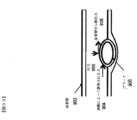
冠動脈疾患は、心臓に血液を供給する血管に冠動脈病変、例えば狭窄(血管の異常な狭小化)を発生させる可能性がある。結果として、心臓への血流が制限される恐れがある。冠動脈疾患に罹患した患者は、身体労作の慢性安定狭心症または安静時の不安定狭心症と称される胸痛を経験し得る。疾患のより重篤な症状は、心筋梗塞または心臓発作につながる恐れがある。Coronary artery disease can cause coronary artery lesions, such as stenoses (abnormal narrowing of blood vessels), in the blood vessels that supply the heart. As a result, blood flow to the heart may be restricted. Patients with coronary artery disease may experience chest pain referred to as chronic stable angina on exertion or unstable angina at rest. More severe symptoms of the disease can lead to myocardial infarction or heart attack.
冠動脈病変に関連するより正確なデータ、例えば、サイズ、形状、位置、機能的重要性(例えば、その病変が血流に影響を及ぼすかどうか)などを提供する必要性が存在する。胸痛を患っている、および/または冠動脈疾患の兆候を示す患者は、冠動脈病変に関連する何らかの間接的な証拠を提供し得る1つまたは複数の検査を受けることがある。例えば、非侵襲的検査には、心電図、血液検査からのバイオマーカー評価、トレッドミル試験、心エコー検査、単一ポジトロン放出コンピュータ断層撮影法(SPECT)、およびポジトロン放出断層撮影法(PET)が含まれるであろう。しかしこれらの非侵襲的検査は、通常は、冠動脈病変の直接的評価を提供しない、または血流量を評価しない。非侵襲的検査は、心臓の電気的活動の変化(例えば、心電図記録法(ECG)を用いて)、心筋の動作(例えば、負荷心エコー法を用いて)、心筋の灌流(例えば、PETまたはSPECTを用いて)、または代謝変化(例えば、バイオマーカーを用いて)を探ることによって冠動脈病変の間接的な証拠を提供することができる。A need exists to provide more accurate data related to coronary artery lesions, such as size, shape, location, functional significance (eg, whether the lesion affects blood flow). A patient suffering from chest pain and/or showing signs of coronary artery disease may undergo one or more tests that may provide some indirect evidence related to coronary artery disease. For example, non-invasive tests include electrocardiogram, biomarker assessment from blood tests, treadmill test, echocardiography, single positron emission computed tomography (SPECT), and positron emission tomography (PET). will be However, these non-invasive tests usually do not provide a direct assessment of coronary artery lesions or assess blood flow. Non-invasive tests include changes in the heart's electrical activity (e.g., using electrocardiography (ECG)), myocardial performance (e.g., using stress echocardiography), myocardial perfusion (e.g., PET or Indirect evidence of coronary artery disease can be provided by probing metabolic changes (eg, using biomarkers), or by probing metabolic changes (using SPECT).
例えば、解剖学的データは、冠動脈コンピュータ断層血管造影(CCTA)によって非侵襲的に取得することができる。CCTAは、胸痛を有する患者の画像化に使用することができ、造影剤の静脈内注入後に心臓および冠動脈を画像化するためのコンピュータ断層撮影(CT)技術の使用を伴う。しかしながら、CCTAは、冠動脈病変の機能的重要性、例えばその病変が血流に影響を及ぼすかどうかについての直接的情報を提供することはできない。さらに、CCTAは単に診断的検査であることから、他の生理学的状態下、例えば運動下での冠状動脈の血流、血圧、または心筋灌流の変化を予想するために使用することはできず、またインターベンションの結果を予想するために使用することもできない。For example, anatomical data can be acquired non-invasively by coronary computed tomography angiography (CCTA). CCTA can be used to image patients with chest pain and involves the use of computed tomography (CT) technology to image the heart and coronary arteries after intravenous injection of contrast agents. However, CCTA cannot provide direct information about the functional significance of coronary artery lesions, eg, whether the lesion affects blood flow. Furthermore, because CCTA is only a diagnostic test, it cannot be used to predict changes in coronary blood flow, blood pressure, or myocardial perfusion under other physiological conditions, such as exercise. Nor can it be used to predict the outcome of an intervention.
したがって、患者は、冠動脈病変を可視化するために診断的心臓カテーテル検査などの侵襲的検査を要することもある。診断的心臓カテーテル検査は、従来の冠動脈造(CCA)を実施して、動脈のサイズおよび形状の画像を医師に提供することによって、冠動脈病変の解剖学的データを収集することを含み得る。しかしながら、CCAは、冠動脈病変の機能的重要性を評価するためのデータは提供しない。例えば、医師は、その病変が機能的に重要であるかどうかを特定せずに、冠動脈病変が有害であるかどうかを診断することはできないかもしれない。したがって、CCAは、病変が機能的に重要であるか否かにかかわらず、CCAで発見されたあらゆる病変にステントを挿入する、一部のインターベンション心臓専門医の「oculostenotic reflex(発見した狭窄に対する反射)」と呼ばれる行為につながっている。結果として、CCAは、患者に対する不必要な手術につながる可能性があり、これは患者に副次的なリスクを与える可能性があり、また患者に不必要な医療費をもたらし得る。Patients may therefore require invasive testing, such as diagnostic cardiac catheterization, to visualize coronary artery lesions. Diagnostic cardiac catheterization may involve collecting anatomical data of coronary artery lesions by performing conventional coronary angioplasty (CCA) to provide the physician with an image of the size and shape of the artery. However, CCA does not provide data to assess the functional significance of coronary artery lesions. For example, a physician may not be able to diagnose whether a coronary artery lesion is harmful without specifying whether the lesion is functionally significant. Therefore, CCA is the "oculostenotic reflex" of some interventional cardiologists, who insert a stent into any lesion found with CCA, whether or not the lesion is functionally important. )” leads to an act called As a result, CCA can lead to unnecessary surgery on the patient, which can pose collateral risks to the patient and can result in unnecessary medical costs for the patient.
診断的心臓カテーテル検査において、観察される病変の冠血流予備量比(FFR)を測定することによって、冠動脈病変の機能的重要性を侵襲的に評価することができる。FFRは、例えばアデノシンの静脈内投与によって誘発される冠動脈血流増加条件下での、病変下流の平均血圧を病変上流の平均血圧、例えば大動脈圧で除算した比として定義される。この血圧は、患者にプレッシャーワイヤーを挿入することによって測定することができる。したがって、特定されたFFRに基づく病変の治療の決定は初期費用後になされ、また診断的心臓カテーテル検査のリスクは既に生じている。In diagnostic cardiac catheterization, the functional significance of coronary artery lesions can be invasively assessed by measuring the fractional coronary flow reserve (FFR) of the observed lesions. FFR is defined as the ratio of the mean blood pressure downstream of the lesion divided by the mean blood pressure upstream of the lesion, eg, the aortic pressure, under conditions of increased coronary blood flow induced, eg, by intravenous administration of adenosine. This blood pressure can be measured by inserting a pressure wire into the patient. Therefore, treatment decisions for identified FFR-based lesions are made after the initial cost, and the risk of diagnostic cardiac catheterization has already arisen.
したがって、冠動脈の解剖学的形態、心筋灌流、および冠動脈血流を非侵襲的に評価する方法に対する必要性が存在する。そのような方法およびシステムは、冠動脈疾患が疑われる患者を診断し、治療を計画する心臓専門医に利益をもたらし得る。さらに、直接測定できない条件下、例えば運動下での冠動脈血流および心筋灌流を予測し、冠動脈血流および心筋灌流に対する薬物治療、インターベンション治療、および外科治療の結果を予測する方法に対する必要性も存在する。Accordingly, there is a need for methods of non-invasively assessing coronary anatomy, myocardial perfusion, and coronary blood flow. Such methods and systems may benefit cardiologists who diagnose and plan treatment for patients with suspected coronary artery disease. There is also a need for methods of predicting coronary blood flow and myocardial perfusion under conditions that cannot be directly measured, such as exercise, and predicting the outcome of drug, interventional, and surgical treatments for coronary blood flow and myocardial perfusion. exist.
前述の一般的な説明および以下の詳細な説明は、どちらも例示的および説明的なものにすぎず、本開示を制限するものではないことを理解すべきである。It is to be understood that both the foregoing general description and the following detailed description are exemplary and explanatory only and are not restrictive of the present disclosure.
一実施形態によると、患者の心血管情報を明らかにするためのシステムは、患者の心臓の幾何学的形状に関する患者固有のデータを受信し、その患者固有のデータに基づく患者の心臓の少なくとも一部を表す三次元モデルを作成するように構成された少なくとも1つのコンピュータシステムを含む。この少なくとも1つのコンピュータシステムは、患者の心臓の血流の特徴に関連する物理学に基づくモデルを作成し、前記三次元モデルとこの物理学に基づくモデルに基づいて、患者の心臓内の冠血流予備量比を特定するようにさらに構成される。According to one embodiment, a system for determining cardiovascular information of a patient receives patient-specific data regarding the geometry of the patient's heart, and performs at least one aspect of the patient's heart based on the patient-specific data. At least one computer system configured to create a three-dimensional model representing the part. The at least one computer system generates a physics-based model associated with blood flow characteristics of the patient's heart, and based on the three-dimensional model and the physics-based model, coronary blood flow within the patient's heart. It is further configured to identify a flow reserve ratio.
別の実施形態によると、少なくとも1つのコンピュータシステムを用いる患者固有の心血管情報を明らかにするための方法は、この少なくとも1つのコンピュータシステムに、患者の心臓の幾何学的形状に関する患者固有のデータを入力することと、この少なくとも1つのコンピュータシステムを用いて、患者固有のデータに基づく患者の心臓の少なくとも一部を表す三次元モデルを作成することとを含む。本方法は、この少なくとも1つのコンピュータシステムを用いて、患者の心臓の血流の特徴に関連する物理学に基づくモデルを作成することと、この少なくとも1つのコンピュータシステムを用いて、三次元モデルおよび物理学に基づくモデルに基づいて患者の心臓内の冠血流予備量比を明らかにすることとをさらに含む。According to another embodiment, a method for determining patient-specific cardiovascular information using at least one computer system comprises providing the at least one computer system with patient-specific data regarding the geometry of the patient's heart. and using the at least one computer system to create a three-dimensional model representing at least a portion of the patient's heart based on the patient-specific data. The method comprises using the at least one computer system to create a physics-based model associated with blood flow characteristics of the patient's heart; Determining a coronary flow reserve ratio in the patient's heart based on a physics-based model.
別の実施形態によると、患者固有の心血管情報を明らかにするための方法を実施するためのコンピュータ実行可能なプログラミング命令を含む、少なくとも1つのコンピュータシステム上で使用するための非一時的なコンピュータ可読媒体が提供される。本方法は、患者の心臓の幾何学的形状に関する患者固有のデータを受信することと、その患者固有のデータに基づいて、患者の心臓の少なくとも一部を表す三次元モデル作成することを含む。本方法は、患者の心臓の血流の特徴に関連する物理学に基づくモデルを作成することと、三次元モデルおよび物理学に基づくモデルに基づいて、患者の心臓内の冠血流予備量比を明らかにすることをさらに含む。According to another embodiment, a non-transitory computer for use on at least one computer system comprising computer-executable programming instructions for performing a method for determining patient-specific cardiovascular information A readable medium is provided. The method includes receiving patient-specific data regarding the geometry of the patient's heart and creating a three-dimensional model representing at least a portion of the patient's heart based on the patient-specific data. The method includes creating a physics-based model associated with blood flow characteristics of the patient's heart and calculating a coronary flow reserve ratio in the patient's heart based on the three-dimensional model and the physics-based model. further comprising revealing the
別の実施形態によると、患者の治療を計画するためのシステムは、患者の解剖学的構造体の幾何学的形状に関する患者固有のデータを受信し、その患者固有のデータに基づく患者の解剖学的構造体の少なくとも一部を表す三次元モデルを作成するように構成された少なくとも1つのコンピュータシステムを含む。この少なくとも1つのコンピュータシステムは、三次元モデルおよび患者の解剖学的構造体に関連する物理学に基づくモデルに基づいて、患者の解剖学的構造体内の血流の特徴に関する第1の情報を明らかにし、三次元モデルを修正し、その修正三次元モデルに基づいて、患者の解剖学的構造体内の血流の特徴に関する第2の情報を明らかにするようにさらに構成される。According to another embodiment, a system for planning treatment of a patient receives patient-specific data regarding the geometry of an anatomical structure of the patient; at least one computer system configured to create a three-dimensional model representing at least a portion of the physical structure. The at least one computer system reveals first information regarding characteristics of blood flow within the patient's anatomy based on the three-dimensional model and a physics-based model associated with the patient's anatomy. and to modify the three-dimensional model and, based on the modified three-dimensional model, reveal second information about blood flow characteristics within the patient's anatomy.
別の実施形態によると、患者の治療を計画するための方法を実行するためのコンピュータ実行可能なプログラミング命令を含む、コンピュータシステム上で使用するための非一時的なコンピュータ可読媒体が提供される。本方法は、患者の解剖学的構造体の幾何学的形状に関する患者固有のデータを受信することと、その患者固有のデータに基づく患者の解剖学的構造体の少なくとも一部を表す三次元モデルを作成することとを含む。本方法は、三次元モデルおよび患者の解剖学的構造体に関連する物理学に基づくモデルに基づいて、患者の解剖学的構造体内の血流の特徴に関する第1の情報を明らかにすることと、患者の解剖学的構造体の幾何学的形状の所望の変化に基づく、患者の解剖学的構造体内の血流の特徴に関する第2の情報を明らかにすることをさらに含む。According to another embodiment, a non-transitory computer-readable medium for use on a computer system containing computer-executable programming instructions for performing a method for planning treatment of a patient is provided. The method comprises: receiving patient-specific data regarding the geometry of a patient's anatomy; and generating a three-dimensional model representing at least a portion of the patient's anatomy based on the patient-specific data. and creating The method reveals first information about characteristics of blood flow within the patient's anatomy based on a three-dimensional model and a physics-based model associated with the patient's anatomy. , further comprising determining second information regarding characteristics of blood flow within the patient's anatomy based on the desired change in the geometry of the patient's anatomy.
別の実施形態によると、コンピュータシステムを用いて患者の治療を計画するための方法は、この少なくとも1つのコンピュータシステムに、患者の解剖学的構造体の幾何学的形状に関する患者固有のデータを入力することと、この少なくとも1つのコンピュータシステムを用いて、患者固有のデータに基づく患者の解剖学的構造体の少なくとも一部を表す三次元モデルを作成することとを含む。本方法は、この少なくとも1つのコンピュータシステムを用いて、三次元モデルおよび患者の解剖学的構造体に関連する物理学に基づくモデルに基づいて、患者の解剖学的構造体内の血流の特徴に関する第1の情報を明らかにすることをさらに含む。また本方法は、この少なくとも1つのコンピュータシステムを用いて三次元モデルを修正することと、この少なくとも1つのコンピュータシステムを用いて、この修正された三次元モデルに基づいて、患者の解剖学的構造体内の血流の特徴に関する第2の情報を明らかにすることとも含む。According to another embodiment, a method for planning treatment of a patient using a computer system comprises inputting patient-specific data regarding the geometry of the patient's anatomy into the at least one computer system. and using the at least one computer system to create a three-dimensional model representing at least a portion of the patient's anatomy based on the patient-specific data. The method uses the at least one computer system to characterize blood flow within the patient's anatomy based on a three-dimensional model and a physics-based model associated with the patient's anatomy. It further includes revealing the first information. The method also includes modifying the three-dimensional model using the at least one computer system, and using the at least one computer system to generate a patient's anatomy based on the modified three-dimensional model. It also includes revealing second information about characteristics of blood flow within the body.
別の実施形態によると、患者の治療を計画するためのシステムは、患者の解剖学的構造体の幾何学的形状に関する患者固有のデータを受信し、その患者固有のデータに基づく患者の解剖学的構造体の少なくとも一部を表す三次元モデルを作成するように構成された少なくとも1つのコンピュータシステムを含む。また、この少なくとも1つのコンピュータシステムは、三次元モデルおよび患者の生理学的状態に関する情報に基づいて、患者の解剖学的構造体内の血流の特徴に関する第1の情報を明らかにし、患者の生理学的状態を修正し、この修正された患者の生理学的状態に基づいて、患者の解剖学的構造体内の血流の特徴に関する第2の情報を明らかにするようにも構成される。According to another embodiment, a system for planning treatment of a patient receives patient-specific data regarding the geometry of an anatomical structure of the patient; at least one computer system configured to create a three-dimensional model representing at least a portion of the physical structure. The at least one computer system also reveals first information about characteristics of blood flow within the patient's anatomy based on the three-dimensional model and the information about the patient's physiological condition, and the patient's physiological condition. It is also configured to modify the condition and, based on this modified physiological condition of the patient, reveal second information regarding blood flow characteristics within the patient's anatomy.
別の実施形態によると、患者の治療を計画するための方法を実施するためのコンピュータ実行可能なプログラミング命令を含む、コンピュータシステム上で使用するための非一時的なコンピュータ可読媒体が提供される。本方法は、患者の解剖学的構造体の幾何学的形状に関する患者固有のデータを受信することと、その患者固有のデータに基づく患者の解剖学的構造体の少なくとも一部を表す三次元モデルを作成することとを含む。本方法は、三次元モデルおよび患者の生理学的状態に関する情報に基づいて、患者の解剖学的構造体内の血流の特徴に関する第1の情報を明らかにすることと、患者の生理学的状態の所望の変化に基づく、患者の解剖学的構造体内の血流の特徴に関する第2の情報を明らかにすることとをさらに含む。According to another embodiment, a non-transitory computer-readable medium for use on a computer system containing computer-executable programming instructions for performing a method for planning treatment of a patient is provided. The method comprises: receiving patient-specific data regarding the geometry of a patient's anatomy; and obtaining a three-dimensional model representing at least a portion of the patient's anatomy based on the patient-specific data. and creating The method comprises, based on a three-dimensional model and information about the patient's physiological state, identifying first information about blood flow characteristics within the patient's anatomy; and determining second information regarding characteristics of blood flow within the patient's anatomy based on changes in .
別の実施形態によると、少なくとも1つのコンピュータシステムを用いる患者の治療を計画するための方法は、この少なくとも1つのコンピュータシステムに、患者の解剖学的構造体の幾何学的形状に関する患者固有のデータを入力することと、この少なくとも1つのコンピュータシステムを使用して、患者固有のデータに基づく患者の解剖学的構造体の少なくとも一部を表す三次元モデルを作成することとを含む。また本方法は、この少なくとも1つのコンピュータシステムを用いて、三次元モデルおよび患者の生理学的状態に関する情報に基づいて、患者の前記解剖学的構造体内の血流の特徴に関する第1の情報を明らかにすることも含む。本方法は、この少なくとも1つのコンピュータシステムを用いて、患者の生理学的状態を修正し、この少なくとも1つのコンピュータシステムを用いて、この修正された患者の生理学的状態に基づいて、患者の解剖学的構造体内の血流の特徴に関する第2の情報を明らかにすることをさらに含む。According to another embodiment, a method for planning treatment of a patient using at least one computer system comprises storing patient-specific data relating to the geometry of the patient's anatomy in the at least one computer system; and using the at least one computer system to create a three-dimensional model representing at least a portion of the patient's anatomy based on the patient-specific data. The method also uses the at least one computer system to determine first information about blood flow characteristics within the anatomical structure of the patient based on the three-dimensional model and information about the physiological state of the patient. It also includes making The method includes using the at least one computer system to modify the physiological condition of the patient and using the at least one computer system to determine the patient's anatomy based on the modified physiological condition of the patient. The method further includes determining second information regarding characteristics of blood flow within the target structure.
別の実施形態によると、患者固有の心血管情報を明らかにするためのシステムは、患者の解剖学的構造体の幾何学的形状に関する患者固有のデータを受信し、その患者固有のデータに基づく患者の解剖学的構造体の少なくとも一部を表す三次元モデルを作成するように構成された少なくとも1つのコンピュータシステムを含む。また、この少なくとも1つのコンピュータシステムは、患者の解剖学的構造体の一部を通る全ての流動に関連する全抵抗を特定し、三次元モデル、患者の解剖学的構造体に関連する物理学に基づくモデル、および特定された全抵抗に基づいて、患者の解剖学的構造体内の血流の特徴に関する情報を明らかにするようにも構成される。According to another embodiment, a system for determining patient-specific cardiovascular information receives patient-specific data regarding the geometry of a patient's anatomy, and performs a method based on the patient-specific data. At least one computer system configured to create a three-dimensional model representing at least a portion of the patient's anatomy. The at least one computer system also identifies a total resistance associated with all flow through a portion of the patient's anatomy and provides a three-dimensional model, physics associated with the patient's anatomy. and based on the identified total resistance, it is also configured to reveal information about the characteristics of blood flow within the patient's anatomy.
別の実施形態によると、少なくとも1つのコンピュータシステムを用いる患者固有の心血管情報を明らかにするための方法は、この少なくとも1つのコンピュータシステムに、患者の解剖学的構造体の幾何学的形状に関する患者固有のデータを入力し、この少なくとも1つのコンピュータを用いて、患者固有のデータに基づく患者の解剖学的構造体の少なくとも一部を表す三次元モデルを作成することを含む。また、本方法は、少なくとも1つのコンピュータを用いて、患者の解剖学的構造体の一部を通る全ての流動と関連する全抵抗を特定することと、少なくとも1つのコンピュータを用いて、三次元モデル、患者の解剖学的構造体に関連する物理学に基づくモデル、および特定された全抵抗に基づいて、患者の解剖学的構造体内の血流の特徴に関する情報を明らかにすることも含む。According to another embodiment, a method for determining patient-specific cardiovascular information using at least one computer system comprises providing the at least one computer system with information relating to the geometry of the patient's anatomy. Entering patient-specific data and using the at least one computer to create a three-dimensional model representing at least a portion of the patient's anatomy based on the patient-specific data. The method also includes determining, using at least one computer, a total resistance associated with all flow through a portion of the patient's anatomy; It also includes characterizing blood flow within the patient's anatomy based on the model, a physics-based model associated with the patient's anatomy, and the determined total resistance.
別の実施形態によると、患者固有の心血管情報を明らかにするための方法を実施するためのコンピュータ実行可能なプログラミング命令を含む、コンピュータシステム上で使用するための非一時的なコンピュータ可読媒体が提供される。本方法は、患者の解剖学的構造体の幾何学的形状に関する患者固有のデータを受信することと、その患者固有のデータに基づく患者の解剖学的構造体の少なくとも一部を表す三次元モデルを作成することとを含む。また、本方法は、患者の解剖学的構造体の一部を通る全ての流動に関連する全抵抗を特定することと、三次元モデル、患者の解剖学的構造体に関連する物理学に基づくモデル、および特定された全抵抗に基づいて、患者の解剖学的構造体内の血流の特徴に関する情報を明らかにすることを含む。According to another embodiment, a non-transitory computer-readable medium for use on a computer system comprising computer-executable programming instructions for performing a method for determining patient-specific cardiovascular information is provided. provided. The method comprises: receiving patient-specific data regarding the geometry of a patient's anatomy; and generating a three-dimensional model representing at least a portion of the patient's anatomy based on the patient-specific data. and creating The method also includes determining the total resistance associated with all flow through a portion of the patient's anatomy and the three-dimensional model, the physics-based flow associated with the patient's anatomy. Based on the model and the determined total resistance, characterizing the blood flow within the patient's anatomy.
別の実施形態によると、ウェブサイトを用いて患者固有の心血管情報を提供するためのシステムは、遠隔のユーザがウェブサイトにアクセスすることを可能にし、患者の解剖学的構造体の幾何学的形状の少なくとも一部に関する患者固有のデータを受信し、その患者固有のデータに基づく患者の解剖学的構造体の少なくとも一部を表す三次元モデルを作成し、その三次元モデルおよび患者の生理学的状態に基づいて、患者の解剖学的構造体内の血流の特徴に関する情報を明らかにするように構成された少なくとも1つのコンピュータシステムを含む。また、この少なくとも1つのコンピュータシステムは、患者の解剖学的構造体の少なくとも一部の第1の三次元シミュレーションに関する表示情報をウェブサイトを用いて遠隔のユーザに伝達するようにも構成される。この三次元シミュレーションは、血流の特徴に関する決定された情報を含む。According to another embodiment, a system for providing patient-specific cardiovascular information using a website enables a remote user to access the website, and to determine the geometry of the patient's anatomy. receiving patient-specific data about at least a portion of a patient's body shape, creating a three-dimensional model representing at least a portion of the patient's anatomy based on the patient-specific data, and comparing the three-dimensional model and the patient's physiology and at least one computer system configured to develop information regarding characteristics of blood flow within the patient's anatomy based on the patient's physical condition. The at least one computer system is also configured to communicate display information regarding the first three-dimensional simulation of at least a portion of the patient's anatomy to the remote user using the website. This three-dimensional simulation contains determined information about blood flow characteristics.
別の実施形態によると、ウェブサイトを用いて患者固有の心血管情報を提供するための方法は、少なくとも1つのコンピュータシステムを用いて、遠隔のユーザがウェブサイトにアクセスすることを可能にすることと、この少なくとも1つのコンピュータシステムを用いて、患者の解剖学的構造体の幾何学的形状に関する患者固有のデータを受信することとを含む。また、本方法は、この少なくとも1つのコンピュータシステムを用いて、患者固有のデータに基づく患者の解剖学的構造体の少なくとも一部を表す三次元モデルを作成することと、この少なくとも1つのコンピュータシステムを用いて、三次元モデルおよび患者の生理学的状態に基づいて、患者の解剖学的構造体内の血流の特徴に関する情報を明らかにすることも含む。本方法は、この少なくとも1つのコンピュータシステムを用いて、患者の解剖学的構造体の少なくとも一部の第1の三次元シミュレーションに関する表示情報をウェブサイトを用いて遠隔のユーザに伝達することをさらに含む。この三次元シミュレーションは、血流の特徴に関する明らかにされた情報を含む。According to another embodiment, a method for providing patient-specific cardiovascular information using a website includes, using at least one computer system, allowing a remote user to access the website. and receiving, with the at least one computer system, patient-specific data regarding the geometry of the patient's anatomy. The method also includes using the at least one computer system to create a three-dimensional model representing at least a portion of the patient's anatomy based on the patient-specific data; is used to reveal information about blood flow characteristics within the patient's anatomy based on the three-dimensional model and the patient's physiological state. The method further comprises using the at least one computer system to communicate display information regarding the first three-dimensional simulation of at least a portion of the patient's anatomy to a remote user using the website. include. This three-dimensional simulation contains revealed information about blood flow characteristics.
別の実施形態によると、ウェブサイトを用いて患者固有の心血管情報を提供するための方法を実施するためのコンピュータ実行可能なプログラミング命令を含む、コンピュータシステム上で使用するための非一時的なコンピュータ可読媒体が提供される。本方法は、遠隔のユーザがウェブサイトにアクセスすることを可能にすることと、患者の解剖学的構造体の幾何学的形状に関する患者固有のデータを受信することと、その患者固有のデータに基づく患者の解剖学的構造体の少なくとも一部を表す三次元モデルを作成することとを含む。また、本方法は、三次元モデルおよび患者の解剖学的構造体に関連する物理学に基づくモデルに基づいて、患者の解剖学的構造体内の血流の特徴に関する情報を明らかにすることと、患者の解剖学的構造体の少なくとも一部の第1の三次元シミュレーションに関する表示情報をウェブサイトを用いて遠隔のユーザに伝達することも含む。この三次元シミュレーションは、血流の特徴に関する明らかにされた情報を含む。According to another embodiment, a non-transitory website for use on a computer system comprising computer-executable programming instructions for performing a method for providing patient-specific cardiovascular information using a website. A computer readable medium is provided. The method includes enabling a remote user to access a website, receiving patient-specific data regarding the geometry of a patient's anatomy, and receiving the patient-specific data. and creating a three-dimensional model representing at least a portion of the patient's anatomy based on. The method also includes characterizing blood flow within the patient's anatomy based on the three-dimensional model and a physics-based model associated with the patient's anatomy; Also included is communicating display information regarding the first three-dimensional simulation of at least a portion of the patient's anatomy to a remote user using the website. This three-dimensional simulation contains revealed information about blood flow characteristics.
別の実施形態によると、患者固有の時変心血管情報を明らかにするためのシステムは、異なる時点の患者の解剖学的構造体の少なくとも一部の幾何学的形状に関する時変患者固有データを受信し、その患者固有のデータに基づく患者の解剖学的構造体の少なくとも一部を表す三次元モデルを作成するように構成された少なくとも1つのコンピュータシステムを含む。また、この少なくとも1つのコンピュータシステムは、三次元モデルおよび患者の解剖学的構造に関連する物理学に基づくモデルに基づいて、患者の解剖学的構造体内の経時的な血流の特徴の変化に関する情報を明らかにするようにも構成される。According to another embodiment, a system for determining patient-specific time-varying cardiovascular information receives time-varying patient-specific data regarding the geometry of at least a portion of a patient's anatomy at different times. and at least one computer system configured to generate a three-dimensional model representing at least a portion of the patient's anatomy based on the patient-specific data. The at least one computer system also relates to changes in blood flow characteristics over time within the patient's anatomy based on the three-dimensional model and a physics-based model associated with the patient's anatomy. It is also configured to reveal information.
別の実施形態によると、少なくとも1つのコンピュータシステムを用いて患者固有の時変心血管情報明らかにするための方法は、少なくとも1つのコンピュータシステムを用いて、異なる時点の患者の解剖学的構造体の幾何学的形状に関する時変患者固有データを受信することを含む。また、本方法は、この少なくとも1つのコンピュータシステムを用いて、患者固有のデータに基づく患者の解剖学的構造体の少なくとも一部を表す三次元モデルを作成することも含む。本方法は、この少なくとも1つのコンピュータシステムを用いて、三次元モデルおよび患者の解剖学的構造体に関連する物理学に基づくモデルに関する情報に基づいて、患者の解剖学的構造体内の経時的な血流の特徴の変化に関する情報を明らかにすることをさらに含む。According to another embodiment, a method for revealing patient-specific time-varying cardiovascular information using at least one computer system comprises: using at least one computer system, a patient's anatomy at different time points; Including receiving time-varying patient-specific data regarding the geometry. The method also includes using the at least one computer system to create a three-dimensional model representing at least a portion of the patient's anatomy based on the patient-specific data. Using the at least one computer system, the method uses information about the three-dimensional model and a physics-based model associated with the patient's anatomy to generate a 3-dimensional image within the patient's anatomy over time. It further includes revealing information about changes in blood flow characteristics.
別の実施形態によると、患者固有の時変心血管情報を明らかにするための方法を実施するためのコンピュータ実行可能なプログラミング命令を含む、コンピュータシステム上で使用するための非一時的なコンピュータ可読媒体が提供される。本方法は、異なる時点の患者の解剖学的構造体の幾何学的形状に関する時変患者固有データを受信することと、その患者固有のデータに基づく患者の解剖学的構造体の少なくとも一部を表す三次元モデルを作成することと、三次元モデルおよび患者の解剖学的構造体に関連する物理学に基づくモデルに関する情報に基づいて、患者の解剖学的構造体内の経時的な血流の特徴の変化に関連する情報を明らかにすることとを含む。According to another embodiment, a non-transitory computer-readable medium for use on a computer system comprising computer-executable programming instructions for performing a method for determining patient-specific time-varying cardiovascular information is provided. The method includes receiving time-varying patient-specific data about the geometry of a patient's anatomy at different points in time and generating at least a portion of the patient's anatomy based on the patient-specific data. Creating a representative three-dimensional model and characterizing blood flow within the patient's anatomy over time based on information about the three-dimensional model and a physics-based model associated with the patient's anatomy. revealing information related to changes in
別の実施形態によると、患者の心血管情報を明らかにするためのシステムは、患者の解剖学的構造体の少なくとも一部の幾何学的形状および少なくとも1つの材料特性に関する患者固有のデータを受信するように構成された少なくとも1つのコンピュータシステムを含む。この解剖学的構造体は、血管の少なくとも一部を含む。この少なくとも1つのコンピュータシステムは、患者固有のデータに基づく患者の解剖学的構造体を表す三次元モデル作成し、その三次元モデルおよび患者の生理学的状態に基づいて、患者の解剖学的構造体内の血流の特徴に関する情報明らかにするようにさらに構成される。また、この少なくとも1つのコンピュータシステムは、血管内のプラークの位置を特定するようにも構成される。According to another embodiment, a system for determining cardiovascular information of a patient receives patient-specific data regarding the geometry and at least one material property of at least a portion of the patient's anatomy. at least one computer system configured to This anatomical structure includes at least a portion of a blood vessel. The at least one computer system creates a three-dimensional model representing the patient's anatomy based on the patient-specific data, and based on the three-dimensional model and the patient's physiological state, within the patient's anatomy. It is further configured to reveal information about the blood flow characteristics of the. The at least one computer system is also configured to locate plaque within the blood vessel.
別の実施形態によると、少なくとも1つのコンピュータシステムを用いて患者の心血管情報を明らかにするための方法は、少なくとも1つのコンピュータシステムを用いて、患者の解剖学的構造体の少なくとも一部の幾何学的形状および少なくとも1つの材料特性に関する患者固有のデータを受信することを含む。この解剖学的構造体は、血管の少なくとも一部を含む。また、本方法は、この少なくとも1つのコンピュータシステムを用いて、患者固有のデータに基づく患者の解剖学的構造体を表す三次元モデルを作成することと、この少なくとも1つのコンピュータシステムを用いて、この三次元モデルおよび患者の生理学的状態に基づいて、患者の解剖学的構造体内の血流の特徴に関する情報を明らかにすることも含む。本方法は、少なくとも1つのコンピュータシステムを用いて、血管内のプラークを特定することをさらに含む。According to another embodiment, a method for determining cardiovascular information of a patient using at least one computer system comprises: using at least one computer system: Receiving patient-specific data regarding geometry and at least one material property. This anatomical structure includes at least a portion of a blood vessel. The method also includes using the at least one computer system to create a three-dimensional model representing the patient's anatomy based on the patient-specific data; and using the at least one computer system to: Based on the three-dimensional model and the patient's physiological state, it also includes determining information about blood flow characteristics within the patient's anatomy. The method further includes identifying plaque within the blood vessel using at least one computer system.
別の実施形態によると、患者の心血管情報を明らかにするための方法を実施するためのコンピュータ実行可能なプログラミング命令を含む、コンピュータシステム上で使用するための非一時的なコンピュータ可読媒体が提供される。本方法は、患者の解剖学的構造体の少なくとも一部の幾何学的形状および少なくとも1つの材料特性に関する患者固有のデータを受信することを含む。この解剖学的構造体は、血管の少なくとも一部を含む。また、本方法は、患者固有のデータに基づく患者の解剖学的構造体を表す三次元モデルを作成することと、その三次元モデルおよび患者の生理学的状態に基づいて、患者の解剖学的構造体内の血流の特徴に関する情報を明らかにすることと、血管内のプラークの位置を特定することも含む。According to another embodiment, a non-transitory computer-readable medium for use on a computer system is provided that includes computer-executable programming instructions for performing a method for determining cardiovascular information of a patient. be done. The method includes receiving patient-specific data regarding the geometry and at least one material property of at least a portion of the patient's anatomy. This anatomical structure includes at least a portion of a blood vessel. The method also includes creating a three-dimensional model representing the patient's anatomy based on the patient-specific data; It also includes characterizing information about blood flow in the body and locating plaque within blood vessels.
別の実施形態によると、患者の心血管情報を明らかにするためのシステムは、患者の解剖学的構造体の少なくとも一部の幾何学的形状に関する患者固有のデータを受信するように構成された少なくとも1つのコンピュータシステムを含む。この解剖学的構造体は、複数の動脈の少なくとも一部と、その複数の動脈の少なくとも一部に連結する組織とを含む。この少なくとも1つのコンピュータシステムは、患者固有のデータに基づく患者の解剖学的構造体を表す三次元モデルを作成し、組織を表す三次元モデルの少なくとも一部をセグメントに分割し、その三次元モデルおよび患者の生理学的状態に基づいて、それらのセグメントのうちの少なくとも1つに関連する血流の特徴に関する情報を明らかにするようにさらに構成される。According to another embodiment, a system for determining cardiovascular information of a patient is configured to receive patient-specific data regarding the geometry of at least a portion of the patient's anatomy. It includes at least one computer system. The anatomical structure includes at least a portion of a plurality of arteries and tissue coupled to at least a portion of the plurality of arteries. The at least one computer system creates a three-dimensional model representing the patient's anatomy based on patient-specific data, segments at least a portion of the three-dimensional model representing tissue, and and the physiological state of the patient to reveal information about blood flow characteristics associated with at least one of the segments.
別の実施形態によると、少なくとも1つのコンピュータシステムを用いて患者の心血管情報を明らかにするための方法は、少なくとも1つのコンピュータシステムを用いて、患者の解剖学的構造体の少なくとも一部の幾何学的形状に関する患者固有のデータを受信することを含む。この解剖学的構造体は、複数の動脈の少なくとも一部と、その複数の動脈の少なくとも一部に連結する組織とを含む。また、本方法は、この少なくとも1つのコンピュータシステムを用いて、患者固有のデータに基づく患者の解剖学的構造体を表す三次元モデルを作成することと、この少なくとも1つのコンピュータシステムを用いて、この三次元モデルを拡張して拡大モデルにすることも含む。本方法は、この少なくとも1つのコンピュータシステムを用いて、組織を表す拡大モデルの少なくとも一部をセグメントに分割することと、この少なくとも1つのコンピュータシステムを用いて、この拡大モデルおよび患者の生理学的状態に基づいて、これらのセグメントのうちの少なくとも1つに関連する血流の特徴に関する情報を明らかにすることをさらに含む。According to another embodiment, a method for determining cardiovascular information of a patient using at least one computer system comprises using at least one computer system to determine at least a portion of the patient's anatomy. Including receiving patient-specific data regarding the geometry. The anatomical structure includes at least a portion of a plurality of arteries and tissue coupled to at least a portion of the plurality of arteries. The method also includes using the at least one computer system to create a three-dimensional model representing the patient's anatomy based on the patient-specific data; using the at least one computer system to: It also includes expanding this three-dimensional model into an enlarged model. The method comprises: using the at least one computer system, segmenting at least a portion of an enlarged model representing tissue; using the at least one computer system, analyzing the enlarged model and the patient's physiological state determining information about blood flow characteristics associated with at least one of the segments based on .
別の実施形態によると、患者の心血管情報を明らかにするための方法を実施するためのコンピュータ実行可能なプログラミング命令を含む、コンピュータシステム上で使用するための非一時的なコンピュータ可読媒体が提供される。本方法は、患者の解剖学的構造体の少なくとも一部の幾何学的形状に関する患者固有のデータを受信することを含む。この解剖学的構造体は、複数の動脈の少なくとも一部と、その複数の動脈の少なくとも一部に連結する組織とを含む。また、本方法は、患者固有のデータに基づく患者の解剖学的構造体を表す三次元モデルを作成することと、組織を表すその三次元モデルの少なくとも一部をセグメントに分割することと、三次元モデルおよび解剖学的構造体に関連する物理学に基づくモデルに基づいて、それらのセグメントのうちの少なくとも1つに関連する血流の特徴に関する情報を明らかにすることも含む。According to another embodiment, a non-transitory computer-readable medium for use on a computer system is provided that includes computer-executable programming instructions for performing a method for determining cardiovascular information of a patient. be done. The method includes receiving patient-specific data regarding the geometry of at least a portion of the patient's anatomy. The anatomical structure includes at least a portion of a plurality of arteries and tissue coupled to at least a portion of the plurality of arteries. The method also includes creating a three-dimensional model representing the patient's anatomy based on the patient-specific data; segmenting at least a portion of the three-dimensional model representing tissue; It also includes determining information about blood flow characteristics associated with at least one of the segments based on the original model and a physics-based model associated with the anatomical structure.
別の実施形態によると、患者の心血管情報を明らかにするためのシステムは、患者の脳の幾何学的形状に関する患者固有のデータを受信するように構成された少なくとも1つのコンピュータシステムを含む。この少なくとも1つのコンピュータシステムは、患者固有のデータに基づく患者の脳の少なくとも一部を表す三次元モデルを作成し、その三次元モデルおよび患者の脳に関連する物理学に基づくモデルに基づいて、患者の脳内の血流の特徴に関する情報を明らかにするようにさらに構成される。According to another embodiment, a system for determining cardiovascular information of a patient includes at least one computer system configured to receive patient-specific data regarding the patient's brain geometry. The at least one computer system creates a three-dimensional model representing at least a portion of the patient's brain based on the patient-specific data, and based on the three-dimensional model and a physics-based model associated with the patient's brain, It is further configured to reveal information about the characteristics of blood flow in the patient's brain.
別の実施形態によると、少なくとも1つのコンピュータシステムを用いる患者固有の心血管情報を明らかにするための方法は、この少なくとも1つのコンピュータシステムに、患者の複数の大脳動脈の少なくとも一部の幾何学的形状に関する患者固有のデータを入力することを含む。また、本方法は、この少なくとも1つのコンピュータシステムを用いて、患者固有のデータに基づく患者の大脳動脈の少なくとも一部を表す三次元モデルを作成することと、この少なくとも1つのコンピュータシステムを用いて、この三次元モデルおよび患者の大脳動脈に関連する物理学に基づくモデルに基づいて、患者の大脳動脈内の血流の特徴に関する情報を明らかにすることも含む。According to another embodiment, a method for determining patient-specific cardiovascular information using at least one computer system comprises storing in the at least one computer system the geometry of at least a portion of a plurality of cerebral arteries of a patient. including entering patient-specific data about physical shape. The method also includes using the at least one computer system to create a three-dimensional model representing at least a portion of the patient's cerebral arteries based on the patient-specific data; , based on this three-dimensional model and a physics-based model associated with the patient's cerebral arteries, characterizing the blood flow in the patient's cerebral arteries.
別の実施形態によると、患者固有の心血管情報を明らかにするための方法を実施するためのコンピュータ実行可能なプログラミング命令を含む、少なくとも1つのコンピュータシステム上で使用するための非一時的なコンピュータ可読媒体が提供される。本方法は、患者の脳の幾何学的形状に関する患者固有のデータを受信することと、その患者固有のデータに基づく患者の脳の少なくとも一部を表す三次元モデルを作成することと、この三次元モデルおよび患者の脳に関連する物理学に基づくモデルに基づいて、患者の脳内の血流の特徴に関する情報を明らかにすることとを含む。
本発明は、例えば以下の項目を提供する。
(項目1)
患者の心血管情報を明らかにするためのシステムであって、前記患者の心臓の幾何学的形状に関する患者固有のデータを受信し、
前記患者固有のデータに基づいて前記患者の心臓の少なくとも一部を表す三次元モデルを作成し、
前記患者の心臓の血流の特徴の特徴に関連する物理学に基づくモデルを作成し、および
前記三次元モデルおよび前記物理学に基づくモデルに基づいて、前記患者の心臓内の冠血流予備量比を特定するように構成された少なくとも1つのコンピュータシステムを備える、システム。
(項目2)
前記患者の心臓の少なくとも前記一部を表す前記三次元モデルが、大動脈の少なくとも一部と、前記大動脈の一部から発する複数の冠動脈の少なくとも一部とを含む、項目1に記載のシステム。
(項目3)
前記冠血流予備量比が、前記大動脈内の圧力と前記複数の冠動脈内のある位置における圧力との比を示し、および
前記少なくとも1つのコンピュータシステムが、前記複数の冠動脈内の複数の位置における前記冠血流予備量比を特定するように構成される、項目2に記載のシステム。
(項目4)
前記患者固有のデータが画像データを含む、項目1に記載のシステム。
(項目5)
前記画像データが、コンピュータ断層撮影または磁気共鳴画像化技術によって提供される、項目4に記載のシステム。
(項目6)
前記少なくとも1つのコンピュータシステムが、前記画像データを用いて前記患者の心臓の冠動脈内腔の境界の位置を特定することによって、前記画像データに基づく前記三次元モデルを作成するように構成される、項目4に記載のシステム。
(項目7)
前記少なくとも1つのコンピュータシステムが、前記画像データにおける輝度値の変化に基づいて前記境界の位置を特定するように構成される、項目6に記載のシステム。
(項目8)
前記物理学に基づくモデルが、前記三次元モデルの境界を通る血流を表す少なくとも1つの集中パラメータモデルを含む、項目1に記載のシステム。
(項目9)
前記少なくとも1つのコンピュータシステムが、充血のレベル、運動のレベル、または薬物のうちの少なくとも1つに関連するパラメータを用いて前記冠血流予備量比を特定するように構成される、項目1に記載のシステム。
(項目10)
前記少なくとも1つのコンピュータシステムが、前記充血のレベルに関連するパラメータを用いて前記冠血流予備量比を特定するように構成され、前記パラメータが、前記患者の冠動脈抵抗、前記患者の大動脈血圧、または前記患者の心拍数に関連する、項目9に記載のシステム。
(項目11)
少なくとも1つのコンピュータシステムを用いて患者固有の心血管情報を明らかにする方法であって、
前記少なくとも1つのコンピュータシステムに、前記患者の心臓の幾何学的形状に関する患者固有のデータを入力することと、
前記少なくとも1つのコンピュータシステムを用いて、前記患者固有のデータに基づく前記患者の心臓の少なくとも一部を表す三次元モデルを作成することと、
前記少なくとも1つのコンピュータシステムを用いて、前記患者の心臓の血流の特徴に関連する物理学に基づくモデルを作成することと、および
前記少なくとも1つのコンピュータシステムを用いて、前記三次元モデルおよび前記物理学に基づくモデルに基づいて前記患者の心臓内の冠血流予備量比を特定することと、を含む、方法。
(項目12)
前記決定された冠血流予備量比に基づいて、前記患者の心臓の冠動脈における機能的に重要な狭窄の位置を特定することをさらに含む、項目11に記載の方法。
(項目13)
前記患者の心臓の少なくとも一部を表す前記三次元モデルが、大動脈の少なくとも一部と、前記大動脈の一部から発する複数の冠動脈の少なくとも一部とを含む、項目11に記載の方法。
(項目14)
前記冠血流予備量比が、前記大動脈内の圧力と前記複数の冠動脈内のある位置における圧力との比を示し、
前記冠血流予備量比が、前記複数の冠動脈内の複数の位置において特定される、項目13に記載の方法。
(項目15)
前記患者固有のデータが、前記患者の心臓の画像データを含み、前記三次元モデルを作成することが、前記画像データを用いて前記患者の心臓の前記複数の冠動脈内腔の境界の位置を特定することを含む、項目14に記載の方法。
(項目16)
前記境界が、前記画像データにおける輝度値の変化に基づいて位置特定される、項目15に記載の方法。
(項目17)
非一時的なコンピュータ可読媒体であって、患者固有の心血管情報を特定するための方法であって、
前記患者の心臓の幾何学的形状に関する患者固有のデータを受信することと、
前記患者固有のデータに基づく前記患者の心臓の少なくとも一部を表す三次元モデルを作成することと、
前記患者の心臓の血流の特徴に関連する物理学に基づくモデルを作成することと、
前記三次元モデルおよび前記物理学に基づくモデルに基づいて、前記患者の心臓内の冠血流予備量比を特定することと、を含む方法を実行するためのコンピュータ実行可能なプログラミング命令を含む、少なくとも1つのコンピュータシステム上で使用するための、非一時的なコンピュータ可読媒体。
(項目18)
前記方法が、
3つの次元に沿って前記心臓の冠動脈中の複数の位置における前記冠血流予備量比を示す前記患者の心臓の三次元シミュレーションを作製することをさらに含む、項目17に記載の非一時的コンピュータ可読媒体。
(項目19)
前記冠血流予備量比が、色または陰影を用いて前記三次元シミュレーション上に示され、前記冠血流予備量比の変化が色または陰影の変化によって示される、項目18に記載の非一時的なコンピュータ可読媒体。
(項目20)
前記患者の心臓の少なくとも一部を表す前記三次元モデルが、大動脈の少なくとも一部と、前記大動脈の一部から発する複数の冠動脈の少なくとも一部とを含み、
前記三次元シミュレーションが、前記冠動脈中の複数の位置における前記冠血流予備量比を含む、項目19に記載の非一時的なコンピュータ可読媒体。
(項目21)
患者の治療を計画するためのシステムであって、
前記患者の解剖学的構造体の幾何学的形状に関する患者固有のデータを受信し、
前記患者固有のデータに基づく前記患者の前記解剖学的構造体の少なくとも一部を表す三次元モデルを作成し、
前記三次元モデルおよび前記患者の前記解剖学的構造体に関連する物理学に基づくモデルに基づいて、前記患者の前記解剖学的構造体内の血流の特徴に関する第1の情報を明らかにし、
前記三次元モデルを修正し、
前記修正された三次元モデルに基づいて、前記患者の前記解剖学的構造体内の前記血流の特徴に関する第2の情報を明らかにするように構成された少なくとも1つのコンピュータシステムを含む、システム。
(項目22)
前記少なくとも1つのコンピュータシステムが、ユーザから受信した入力であって、前記患者の治療計画の選択を含む入力に基づいて、前記三次元モデルを修正するようにさらに構成される、項目21に記載のシステム。
(項目23)
前記選択された治療計画が、前記患者の前記解剖学的構造体の前記幾何学的形状の変化に関連し、
前記少なくとも1つのコンピュータシステムが、前記選択された治療計画に基づいて、前記三次元モデルを修正するようにさらに構成される、項目22に記載のシステム。
(項目24)
前記受信される入力が、前記解剖学的構造体の前記幾何学的形状を変化させるための前記患者の前記解剖学的構造体における位置を含み、前記位置は前記ユーザによって選択され、
前記少なくとも1つのコンピュータシステムが、前記選択された治療計画および前記選択された位置に基づいて、前記三次元モデルを修正するようにさらに構成される、項目23に記載のシステム。
(項目25)
前記選択された治療計画が、前記患者の前記選択された位置にステントを挿入する計画を含み、
前記少なくとも1つのコンピュータシステムが、前記三次元モデルによって表される内腔を拡大することによって前記三次元モデルを修正するようにさらに構成される、項目24に記載のシステム。
(項目26)
前記選択された治療計画が、前記患者の前記選択された位置にバイパスを追加する計画を含み、および
前記少なくとも1つのコンピュータシステムが、前記三次元モデルにおいて内腔に向かって第1のバイパスを追加することによって前記三次元モデルを修正するようにさらに構成される、項目24に記載のシステム。
(項目27)
前記少なくとも1つのコンピュータシステムが、
前記患者の前記解剖学的構造体内の複数の位置において前記第1の情報と前記第2の情報との差を明らかにするようにさらに構成される、項目21に記載のシステム。
(項目28)
前記第1の情報および前記第2の情報がそれぞれ、前記患者の前記解剖学的構造体内の血圧、血液速度、血流量、または冠血流予備量比うちの少なくとも1つを含む、項目21に記載のシステム。
(項目29)
前記患者の前記解剖学的構造体が、前記患者の心臓、頸部、頭部、胸部、腹部、腕、または脚の複数の動脈の一部のうちの少なくとも1つを含む、項目21に記載のシステム。
(項目30)
非一時的なコンピュータ可読媒体であって、患者の治療を計画するための方法であって、前記患者の解剖学的構造体の幾何学的形状に関する患者固有のデータを受信することと、前記患者固有のデータに基づく前記患者の解剖学的構造体の少なくとも一部を表す三次元モデルを作成することと、
前記三次元モデルおよび前記患者の前記解剖学的構造体に関連する物理学に基づくモデルに基づいて、前記患者の前記解剖学的構造体内の血流の特徴に関する第1の情報を明らかに明らかにすることと、前記患者の前記解剖学的構造体の幾何学的形状の所望の変化に基づいて、前記患者の前記解剖学的構造体内の前記血流の特徴に関する第2の情報を明らかにすることと、を含む方法を実行するためのコンピュータ実行可能なプログラミング命令を含む、コンピュータシステム上で使用するための、非一時的なコンピュータ可読媒体。(項目31)
前記方法が、
治療計画を選択するユーザから受信する入力に基づいて、前記三次元モデルを修正することと、
前記修正に基づいて、前記第2の情報を明らかにすることをさらに含む、項目30に記載の非一時的なコンピュータ可読媒体。
(項目32)
前記選択された治療計画が、前記患者の前記解剖学的構造体の前記幾何学的形状の変化と関連し、
前記少なくとも1つのコンピュータシステムが、前記選択された治療計画に基づいて前記三次元モデルを修正するようにさらに構成される、項目31に記載の非一時的なコンピュータ可読媒体。
(項目33)
前記受信された入力が、前記解剖学的構造体の前記幾何学的形状を変化させるための前記患者の前記解剖学的構造体における位置を含み、
前記少なくとも1つのコンピュータシステムが、前記選択された治療計画および前記選択された位置に基づいて前記三次元モデルを修正するようにさらに構成される、項目32に記載の非一時的コンピュータ可読媒体。
(項目34)
前記方法が、
前記患者の前記解剖学的構造体内の複数の位置における前記第1の情報と前記第2の情報との差を明らかにすることをさらに含む、項目30に記載の非一時的なコンピュータ可読媒体。
(項目35)
前記第1の情報および前記第2の情報がそれぞれ、前記患者の前記解剖学的構造体内の血圧、血液速度、血流量、または冠血流予備量比を含む、項目30に記載の非一時的なコンピュータ可読媒体。
(項目36)
前記患者の前記解剖学的構造体が、前記患者の心臓、頸部、頭部、胸部、腹部、腕、または脚の複数の動脈の一部のうちの少なくとも1つを含む、項目30に記載の非一時的なコンピュータ可読媒体。
(項目37)
コンピュータシステムを用いて患者の治療を計画するための方法であって、
少なくとも1つのコンピュータシステムに、前記患者の解剖学的構造体の幾何学的形状に関する患者固有のデータを入力することと、
前記少なくとも1つのコンピュータシステムを用いて、前記患者固有のデータに基づく前記患者の前記解剖学的構造体の少なくとも一部を表す三次元モデルを作成することと、
前記少なくとも1つのコンピュータシステムを用いて、前記三次元モデルおよび前記患者の前記解剖学的構造体に関連する物理学に基づくモデルに基づいて、前記患者の前記解剖学的構造体内の血流の特徴に関する第1の情報を明らかにすることと、
前記少なくとも1つのコンピュータシステムを用いて、前記三次元モデルを修正することと、および前記少なくとも1つのコンピュータシステムを用いて、前記修正三次元モデルに基づいて前記患者の前記解剖学的構造体内の前記血流の特徴に関する第2の情報を明らかにすることと、を含む、方法。
(項目38)
前記少なくとも1つのコンピュータシステムを用いて、前記第1の情報を含む三次元シミュレーションを作成することと、
前記少なくとも1つのコンピュータシステムを用いて、前記三次元シミュレーションに基づく次数低減モデルを作成することをさらに含み、
前記第2の情報が前記次数低減モデルを用いて明らかにされる、項目37に記載の方法。(項目39)
前記次数低減モデルが集中パラメータモデルである、項目38に記載の方法。
(項目40)
前記三次元モデルが、ユーザから受信する第1の入力であって、前記ユーザによって選択された第1の治療計画を示す第1の入力に基づいて修正される、項目37に記載の方法であって、
前記少なくとも1つのコンピュータシステムを用いて、前記第1の入力とは別に、前記ユーザから受信する第2の入力であって、前記ユーザによって選択された第2の治療計画を示す第2の入力に基づいて前記三次元モデルを修正することと、および
前記少なくとも1つのコンピュータシステムを用いて、前記第2の入力に基づいて修正された前記三次元モデルに基づいて、前記患者の前記解剖学的構造体内の前記血流の特徴に関する第3の情報を明らかにすることと、および
前記第2の情報を前記第3の情報と比較することによって、前記第1および第2の治療計画を比較することと、をさらに含む、方法。
(項目41)
患者の治療を計画するためのシステムであって、
前記患者の解剖学的構造体の幾何学的形状に関する患者固有のデータを受信し、
前記患者固有のデータに基づく前記患者の前記解剖学的構造体の少なくとも一部を表す三次元モデルを作成し、
前記三次元モデルおよび前記患者の生理学的状態に関する情報に基づいて、前記患者の前記解剖学的構造体内の血流の特徴に関する第1の情報を明らかにし、
前記患者の前記生理学的状態を修正し、
前記患者の前記修正された生理学的状態に基づいて、前記患者の前記解剖学的構造体内の前記血流の特徴に関する第2の情報を明らかにするように構成された少なくとも1つのコンピュータシステムを備える、システム。
(項目42)
前記少なくとも1つのコンピュータシステムが、ユーザから受信する入力であって、前記患者のための治療計画の選択を含む入力に基づいて、前記患者の前記生理学的状態を修正するようにさらに構成される、項目41に記載のシステム。
(項目43)
前記選択された治療計画が、前記患者の心拍出量、運動のレベル、充血のレベル、または薬物療法のうちの少なくとも1つの変化に関連し、
前記少なくとも1つのコンピュータシステムが、前記選択された治療計画に基づいて前記患者の前記生理学的状態を修正するようにさらに構成される、項目42に記載のシステム。
(項目44)
前記少なくとも1つのコンピュータシステムが、前記患者の前記解剖学的構造体を通る血流に関連するパラメータを変化させることによって、前記患者の前記生理学的状態を修正するようにさらに構成される、項目43に記載のシステム。
(項目45)
前記変化させた血流に関するパラメータが、冠動脈抵抗、大動脈血圧、または心拍数のうちの少なくとも1つを含む、項目44に記載のシステム。
(項目46)
前記少なくとも1つのコンピュータシステムが、
前記患者の前記解剖学的構造体内の複数の位置における前記第1の情報と前記第2の情報との差を明らかにするようにさらに構成される、項目41に記載のシステム。
(項目47)
前記第1の情報および前記第2の情報がそれぞれ、前記患者の前記解剖学的構造体内の血圧、血液速度、血流量、または冠血流予備量比のうちの少なくとも1つを含む、項目41に記載のシステム。
(項目48)
前記患者の前記解剖学的構造体が、前記患者の心臓、頸部、頭部、胸部、腹部、腕、または脚の複数の動脈の一部のうちの少なくとも1つを含む、項目41に記載のシステム。
(項目49)
非一時的なコンピュータ可読媒体であって、患者の治療を計画するための方法であって、前記患者の解剖学的構造体の幾何学的形状に関する患者固有のデータを受信することと、前記患者固有のデータに基づく前記患者の解剖学的構造体の少なくとも一部を表す三次元モデルを作成することと、
前記三次元モデルおよび前記患者の生理学的状態に関する情報に基づいて、前記患者の前記解剖学的構造体内の血流の特徴に関する第1の情報を明らかにすることと、および
前記患者の前記生理学的状態の変化に基づいて、前記患者の前記解剖学的構造体内の前記血流の特徴に関する第2の情報を明らかにすることと、を含む、方法を実行するためのコンピュータ実行可能なプログラミング命令を含むコンピュータシステム上で使用するための、非一時的なコンピュータ可読媒体。
(項目50)
前記第2の情報が、前記患者の心拍出量、心拍数、一回拍出量、血圧、労作または運動のレベル、充血のレベル、または薬物療法のうちの少なくとも1つの変化に関連する選択された治療計画に基づいて明らかにされる、項目49に記載の非一時的なコンピュータ可読媒体。
(項目51)
前記方法が、前記患者の前記解剖学的構造体を通る血流に関連するパラメータを変化させることによって、前記患者の前記生理学的状態を修正することをさらに含む、項目50に記載の非一時的なコンピュータ可読媒体。
(項目52)
前記変化させた血流に関するパラメータが、冠動脈抵抗、大動脈血圧、または心拍数のうちの少なくとも1つを含む、項目51に記載の非一時的なコンピュータ可読媒体。
(項目53)
前記方法が、
前記患者の前記解剖学的構造体内の複数の位置において前記第1の情報と前記第2の情報との差を明らかにすることをさらに含む、項目49に記載の非一時的なコンピュータ可読媒体。
(項目54)
前記第1の情報および前記第2の情報がそれぞれ、前記患者の前記解剖学的構造体内の血圧、血液速度、血流量、または冠血流予備量比のうちの少なくとも1つを含む、項目49に記載の非一時的なコンピュータ可読媒体。
(項目55)
前記患者の前記解剖学的構造体が、前記患者の心臓、頸部、頭部、胸部、腹部、腕、または脚の複数の動脈の一部のうちの少なくとも1つを含む、項目49に記載の非一時的なコンピュータ可読媒体。
(項目56)
少なくとも1つのコンピュータシステムを用いて患者の治療を計画するための方法であって、少なくとも1つのコンピュータシステムに、前記患者の解剖学的構造体の幾何学的形状に関する患者固有のデータを入力することと、
前記少なくとも1つのコンピュータシステムを用いて、前記患者固有のデータに基づく前記患者の前記解剖学的構造体の少なくとも一部を表す三次元モデルを作成することと、
前記少なくとも1つのコンピュータシステムを用いて、前記三次元モデルおよび前記患者の生理学的状態に関する情報に基づいて、前記患者の前記解剖学的構造体内の血流の特徴に関する第1の情報を明らかにすることと、
前記少なくとも1つのコンピュータシステムを用いて、前記患者の前記生理学的状態を修正することと、および
前記少なくとも1つのコンピュータシステムを用いて、前記患者の前記修正された生理学的状態に基づいて、前記患者の前記解剖学的構造体内の前記血流の特徴に関する第2の情報を明らかにすることと、を含む、方法。
(項目57)
前記患者の前記生理学的状態を修正することが、前記患者の前記解剖学的構造体を通る血流に関するパラメータを変更することを含み、
前記変更されたパラメータが、冠動脈抵抗、大動脈血圧、または心拍数のうちの少なくとも1つを含む、項目56に記載の方法。
(項目58)
前記少なくとも1つのコンピュータシステムを用いて、前記第1の情報を含む三次元シミュレーションを作成することと、および
前記少なくとも1つのコンピュータシステムを用いて、前記三次元シミュレーションに基づく次数低減モデルを作成することをさらに含み、
前記第2の情報が前記次数低減モデルを用いて明らかにされる、項目56に記載の方法。(項目59)
前記次数低減モデルが集中パラメータモデルである、項目58に記載の方法。
(項目60)
前記患者の前記生理学的状態を修正することが、前記ユーザから受信した第1の入力のであって、前記ユーザによって選択された第1の治療計画を示す第1の入力に基づく項目56に記載の方法であって、
前記少なくとも1つのコンピュータシステムを用いて、前記第1の入力とは別に、前記ユーザから受信する第2の入力であって、前記ユーザによって選択された第2の治療計画を示す第2の入力に基づいて前記患者の前記生理学的状態を修正することと、
前記少なくとも1つのコンピュータシステムを用いて、前記第2の入力に基づいて修正された前記生理学的状態に基づいて、前記患者の前記解剖学的構造体内の前記血流の特徴に関する第3の情報を明らかにすることと、および
前記第2の情報と前記第3の情報とを比較することによって、前記第1および第2の治療計画を比較することと、をさらに含む、方法。
(項目61)
患者固有の心血管情報を明らかに明らかにするためのシステムであって、
前記患者の解剖学的構造体の幾何学的形状に関する患者固有のデータを受信し、
前記患者固有のデータに基づく前記患者の前記解剖学的構造体の少なくとも一部を表す三次元モデルを作成し、
前記患者の前記解剖学的構造体の前記一部を通る全流量に関連する全抵抗を特定し、
前記三次元モデル、前記患者の前記解剖学的構造体に関連する物理学に基づくモデル、および前記特定された全抵抗に基づいて、前記患者の前記解剖学的構造体内の血流の特徴に関する情報を明らかにするように構成された少なくとも1つのコンピュータシステムを備える、システム。
(項目62)
前記患者の前記解剖学的構造体が、大動脈の少なくとも一部と、前記大動脈の一部から発する複数の冠動脈の少なくとも一部とを含み、および前記全抵抗が前記複数の冠動脈を通る全流出量に関連する、項目61に記載のシステム。(項目63)
前記少なくとも1つのコンピュータシステムが、前記決定された全抵抗に基づいて前記複数の冠動脈それぞれの個々の抵抗を特定し、および
前記個々の抵抗を前記物理学に基づくモデルに組込むことによって、前記特定された個々の抵抗に基づいて前記血流の特徴に関する前記情報を明らかにするようにさらに構成される、項目62に記載のシステム。
(項目64)
前記少なくとも1つのコンピュータシステムが、
前記患者の測定された血圧を受信し、
前記測定された血圧に基づいて前記全抵抗を特定するようにさらに構成される、項目63に記載のシステム。
(項目65)
前記少なくとも1つのコンピュータシステムが、前記解剖学的構造体の少なくとも一部の特定された質量または体積に基づいて、前記解剖学的構造体の前記一部を通る前記全流量を特定するようにさらに構成される、項目61に記載のシステム。
(項目66)
前記少なくとも1つのコンピュータシステムが、前記患者固有のデータを用いて、前記解剖学的構造体の少なくとも一部の前記質量または体積を特定するようにさらに構成される、項目65に記載のシステム。
(項目67)
前記患者固有のデータが画像データを含み、前記少なくとも1つのコンピュータシステムが、前記画像データを用いて、前記解剖学的構造体の少なくとも一部の前記質量または体積を特定するようにさらに構成される、項目66に記載のシステム。
(項目68)
前記情報が、前記患者の解剖学的構造体内の血圧、血液速度、または血流量を含む、項目61に記載のシステム。
(項目69)
前記患者の前記解剖学的構造体が、前記患者の心臓、頸部、頭部、胸部、腹部、腕、または脚の複数の動脈の一部のうちの少なくとも1つを含む、項目61に記載のシステム。
(項目70)
少なくとも1つのコンピュータシステムを用いて患者固有の心血管情報を明らかにするための方法であって、
前記少なくとも1つのコンピュータシステムに、前記患者の解剖学的構造体の幾何学的形状に関する患者固有のデータを入力することと、
少なくとも1つのコンピュータシステムを用いて、前記患者固有のデータに基づく前記患者の前記解剖学的構造体の少なくとも一部を表す三次元モデルを作成することと、
少なくとも1つのコンピュータを用いて、前記患者の前記解剖学的構造体の前記一部を通る全流量に関連する全抵抗を特定することと、および
少なくとも1つのコンピュータを用いて、前記三次元モデル、前記患者の前記解剖学的構造体に関連する物理学に基づくモデル、および前記決定された全抵抗に基づいて、前記患者の前記解剖学的構造体内の血流の特徴に関する情報を明らかにすることと、を含む、方法。
(項目71)
前記少なくとも1つのコンピュータシステムを用いて、前記患者固有のデータを使用して、前記患者の前記解剖学的構造体の少なくとも一部の質量または体積を特定することと、および
前記少なくとも1つのコンピュータシステムを用いて、前記特定された質量または体積に基づく前記全流量を特定することをさらに含む、項目70に記載の方法。
(項目72)
前記患者の前記解剖学的構造体が、前記患者の心筋または脳である、項目71に記載の方法。
(項目73)
前記患者の血圧を測定することをさらに含み、前記全抵抗が前記測定された血圧に基づいて特定される、項目71に記載の方法。
(項目74)
前記患者の前記解剖学的構造体が、複数の連結する動脈の少なくとも一部を含む項目73に記載の方法であって、
前記少なくとも1つのコンピュータシステムを用いて、前記特定された全抵抗に基づいて、前記複数の動脈それぞれの個々の抵抗を特定することをさらに含む、方法。
(項目75)
前記情報が、前記患者の解剖学的構造体内の血圧、血液速度、または血流量を含む、項目70に記載の方法。
(項目76)
前記患者の前記解剖学的構造体が、前記患者の心臓、頸部、頭部、胸部、腹部、腕、または脚の複数の動脈の一部のうちの少なくとも1つを含む、項目70に記載の方法。
(項目77)
非一時的なコンピュータ可読媒体であって、患者固有の心血管情報を明らかにするための方法であって、
前記患者の解剖学的構造体の幾何学的形状に関する患者固有のデータを受信することと、前記患者固有のデータに基づく前記患者の解剖学的構造体の少なくとも一部を表す三次元モデルを作成することと、
前記患者の前記解剖学的構造体の前記一部を通る全流量に関連する全抵抗を特定することと、および
前記三次元モデル、前記患者の前記解剖学的構造体に関連する物理学に基づくモデル、および前記特定された全抵抗に基づいて、前記患者の前記解剖学的構造体内の血流の特徴に関する情報を明らかにすることを含む方法を実施するためのコンピュータ実行可能なプログラミング命令を含む、コンピュータシステム上で使用するための、非一時的なコンピュータ可読媒体。
(項目78)
前記患者の前記解剖学的構造体が、大動脈の少なくとも一部と、前記大動脈の前記一部から発する複数の冠動脈の少なくとも一部とを含み、
前記全抵抗が、前記複数の冠動脈を通る全流出量に関連する、項目77に記載の非一時的なコンピュータ可読媒体。
(項目79)
前記方法が、
前記解剖学的構造体の少なくとも一部の特定された質量または体積に基づいて、前記解剖学的構造体の一部を通る前記全流量を特定することをさらに含む、項目77に記載の非一時的なコンピュータ可読媒体。
(項目80)
前記患者固有のデータが画像データを含み、前記方法が、
前記画像データを用いて、前記解剖学的構造体の少なくとも一部の前記質量または体積を特定することをさらに含む、項目79に記載の非一時的なコンピュータ可読媒体。
(項目81)
ウェブサイトを用いて患者固有の心血管情報を提供するためのシステムであって、
遠隔ユーザがウェブサイトにアクセスすることを可能にし、
前記患者の解剖学的構造体の幾何学的形状の少なくとも一部に関する患者固有のデータを受信し、
前記患者固有のデータに基づく前記患者の前記解剖学的構造体の少なくとも一部を表す三次元モデルを作成し、前記三次元モデルおよび前記患者の生理学的状態に基づいて、前記患者の前記解剖学的構造体内の血流の特徴に関する情報を明らかにし、前記患者の前記解剖学的構造体の少なくとも前記一部の第1の三次元シミュレーションであって、前記血流の特徴に関する前記明らかにされた情報を含む三次元シミュレーションに関する表示情報を前記ウェブサイトを用いて前記遠隔ユーザに伝達するように構成された少なくとも1つのコンピュータシステムを備える、システム。
(項目82)
前記少なくとも1つのコンピュータシステムが、
前記ウェブサイトを介して、前記患者の治療計画を選択する前記遠隔ユーザからの入力を受信するようにさらに構成される、項目81に記載のシステム。
(項目83)
前記少なくとも1つのコンピュータシステムが、
前記受信された入力に基づいて、前記三次元モデルまたは前記患者の前記生理学的状態のうちの少なくとも1つを修正し、
前記受信された入力に基づいて、前記患者の前記解剖学的構造体内の前記血流の特徴に関する第2の情報を明らかにするようにさらに構成される、項目82に記載のシステム。
(項目84)
前記少なくとも1つのコンピュータシステムが、
前記患者の前記解剖学的構造体の少なくとも前記一部の第2の三次元シミュレーションであって、前記血流の特徴に関する前記明らかにされた第2の情報を含む第2の三次元シミュレーションに関する表示情報を前記ウェブサイトを用いて前記遠隔ユーザに伝達するようにさらに構成される、項目83に記載のシステム。
(項目85)
前記患者の前記解剖学的構造体内の前記血流の特徴に関する前記情報が、前記患者の前記解剖学的構造体に関連する保存された物理学に基づくモデルに基づいてさらに明らかにされる、項目81に記載のシステム。
(項目86)
前記患者の前記解剖学的構造体が、心臓、頸部、頭部、胸部、腹部、腕、または脚の複数の動脈の一部のうちの少なくとも1つを含む、項目81に記載のシステム。
(項目87)
前記情報が、前記患者の解剖学的構造体内の血圧、血液速度、または血流量を含む、項目81に記載のシステム。
(項目88)
前記少なくとも1つのコンピュータシステムが、
複数の患者に関する患者固有のデータを受信し、および
前記複数の患者の前記血流の特徴に関する前記情報を明らかにするようにさらに構成される、項目81に記載のシステム。
(項目89)
前記少なくとも1つのコンピュータシステムが、複数の遠隔ユーザが前記ウェブサイトに安全にアクセスすることを可能にするように構成される、項目81に記載のシステム。
(項目90)
前記少なくとも1つのコンピュータシステムが、前記三次元モデルに関する表示情報を前記ウェブサイトを用いて前記遠隔ユーザに伝達するように構成される、項目81に記載のシステム。
(項目91)
ウェブサイトを用いて患者固有の心血管情報を提供するための方法であって、
少なくとも1つのコンピュータシステムを用いて、遠隔ユーザがウェブサイトにアクセスすることを可能にすることと、
前記少なくとも1つのコンピュータシステムを用いて、前記患者の解剖学的構造体の幾何学的形状に関する患者固有のデータを受信することと、
前記少なくとも1つのコンピュータシステムを用いて、前記患者固有のデータに基づく前記患者の前記解剖学的構造体の少なくとも一部を表す三次元モデルを作成することと、前記少なくとも1つのコンピュータシステムを用いて、前記三次元モデルおよび前記患者の生理学的状態に基づいて、前記患者の前記解剖学的構造体内の血流の特徴に関する情報を明らかにすることと、および
前記少なくとも1つのコンピュータシステムを用いて、前記患者の前記解剖学的構造体の少なくとも前記一部の第1の三次元シミュレーションであって、前記血流の特徴に関する前記明らかにされた情報を含む三次元シミュレーションに関する表示情報を前記ウェブサイトを用いて前記遠隔ユーザに伝達することと、を含む、方法。
(項目92)
前記少なくとも1つのコンピュータシステムを用いて、前記ウェブサイトを使用して、前記患者の治療計画を選択する前記遠隔ユーザからの入力を受信することをさらに含む、項目91に記載の方法。
(項目93)
前記少なくとも1つのコンピュータシステムを用いて、前記受信された入力に基づいて、前記三次元モデルまたは前記患者の前記生理学的状態のうちの少なくとも1つを修正することと、および
前記少なくとも1つのコンピュータシステムを用いて、前記受信された入力に基づいて、前記患者の前記解剖学的構造体の少なくとも前記一部の前記血流の特徴に関する第2の情報を明らかにすることをさらに含む、項目92に記載の方法。
(項目94)
前記少なくとも1つのコンピュータシステムを用いて、前記患者の前記解剖学的構造体の第2の三次元シミュレーションであって、前記血流の特徴に関する前記明らかにされた第2の情報を含む第2の三次元シミュレーションに関する表示情報を前記ウェブサイトを用いて前記遠隔ユーザに伝達することをさらに含む、項目93に記載の方法。
(項目95)
非一時的なコンピュータ可読媒体であって、患者固有の心血管情報をウェブサイトを用いて提供するための方法であって、
遠隔ユーザがウェブサイトにアクセスすることを可能にすることと、
前記患者の解剖学的構造体の幾何学的形状に関する患者固有のデータを受信することと、前記患者固有のデータに基づく前記患者の解剖学的構造体の少なくとも一部を表す三次元モデルを作成することと、
前記三次元モデルおよび前記患者の前記解剖学的構造体に関連する物理学に基づくモデルに基づいて、前記患者の前記解剖学的構造体内の血流の特徴に関する第1の情報を明らかにすることと、および
前記患者の前記解剖学的構造体の少なくとも前記一部の第1の三次元シミュレーションであって、前記血流の特徴に関する前記明らかにされた情報を含む三次元シミュレーションに関する表示情報を前記ウェブサイトを用いて前記遠隔ユーザに伝達することと、を含む方法を実施するためのコンピュータ実行可能なプログラミング命令を含む、コンピュータシステム上で使用するための、非一時的なコンピュータ可読媒体。
(項目96)
前記方法が、
前記ウェブサイトを用いて、前記患者の治療計画を選択する前記遠隔ユーザからの入力を受信することをさらに含む、項目95に記載の非一時的なコンピュータ可読媒体。
(項目97)
前記患者の前記解剖学的構造体の少なくとも前記一部の前記血流の特徴に関する前記情報が、前記患者の前記解剖学的構造体に関連する保存された物理学に基づくモデルに基づいてさらに明らかにされる、項目95に記載の非一時的なコンピュータ可読媒体。
(項目98)
前記患者の前記解剖学的構造体が、前記患者の心臓、頸部、頭部、胸部、腹部、腕、または脚の複数の動脈の一部のうちの少なくとも1つを含む、項目95に記載の非一時的なコンピュータ可読媒体。
(項目99)
前記方法が、
複数の患者に関する患者固有のデータを受信することと、および
前記複数の患者の前記血流の特徴に関する前記情報を明らかにすることをさらに含む、項目95に記載の非一時的なコンピュータ可読媒体。
(項目100)
前記少なくとも1つのコンピュータシステムが、複数の遠隔ユーザが前記ウェブサイトに安全にアクセスすることを可能にするように構成される、項目95に記載の非一時的なコンピュータ可読媒体。
(項目101)
患者固有の時変心血管情報を明らかにするためのシステムであって、
異なる時点の前記患者の解剖学的構造体の少なくとも一部の幾何学的形状に関する時変患者固有のデータを受信し、
前記患者固有のデータに基づく前記患者の前記解剖学的構造体の少なくとも一部を表す三次元モデルを作成し、および
前記三次元モデルおよび前記患者の前記解剖学的構造に関連する物理学に基づくモデルに基づいて、前記患者の前記解剖学的構造体内の経時的な血流の特徴の変化に関する情報を明らかにするように構成される少なくとも1つのコンピュータシステムを備える、システム。
(項目102)
前記時変患者固有のデータが、異なる時点の前記患者の前記解剖学的構造体の前記幾何学的形状に関するものである、項目101に記載のシステム。
(項目103)
前記患者固有のデータが、心周期にわたる異なる時点の画像データを含む、項目101に記載のシステム。
(項目104)
前記患者の前記解剖学的構造体が、前記患者の複数の連結する動脈の少なくとも一部を含み、
前記患者固有のデータが、前記複数の動脈血管形状の変化に関する情報を含む、項目101に記載のシステム。
(項目105)
前記複数の動脈が、前記患者の心臓、頸部、頭部、胸部、腹部、腕、または脚に位置する、項目104に記載のシステム。
(項目106)
前記血流の特徴が、血圧、血液速度、または血流量のうちの少なくとも1つを含む、項目101に記載のシステム。
(項目107)
前記少なくとも1つのコンピュータシステムが、
前記患者の前記解剖学的構造体内の3つの次元に沿った複数の位置における経時的な前記血流の特徴の変化に関する情報を明らかにするようにさらに構成される、項目101に記載のシステム。
(項目108)
少なくとも1つのコンピュータシステムを用いて患者固有の時変心血管情報を明らかにするための方法であって、
少なくとも1つのコンピュータシステムを用いて、異なる時点の前記患者の解剖学的構造体の幾何学的形状に関する時変患者固有のデータを受信することと、
前記少なくとも1つのコンピュータシステムを用いて、前記患者固有のデータに基づく前記患者の前記解剖学的構造体の少なくとも一部を表す三次元モデルを作成することと、および
前記少なくとも1つのコンピュータシステムを用いて、前記三次元モデルおよび前記患者の前記解剖学的構造体に関連する物理学に基づくモデルに関する前記情報に基づいて、前記患者の前記解剖学的構造体内の経時的な血流の特徴の変化に関する情報を明らかにすることと、を含む、方法。
(項目109)
前記少なくとも1つのコンピュータシステムを用いて前記物理学に基づくモデルを保存することをさらに含む、項目108に記載の方法。
(項目110)
前記患者の前記解剖学的構造体が、前記患者の心臓、頸部、頭部、胸部、腹部、腕、または脚の複数の動脈の一部のうちの少なくとも1つを含む、項目108に記載の方法。
(項目111)
前記時変患者固有のデータが、異なる時点の前記患者の前記解剖学的構造体の前記幾何学的形状に関連する、項目108に記載の方法。
(項目112)
前記患者固有のデータが、心周期にわたる異なる時点の画像データを含む、項目108に記載の方法。
(項目113)
前記患者の前記解剖学的構造体が、前記患者の複数の連結する動脈の少なくとも一部を含み、および
前記患者固有のデータが、前記複数の動脈の血管形状の変化に関する情報を含む、項目108に記載の方法。
(項目114)
前記複数の動脈が、前記患者の心臓、頸部、頭部、胸部、腹部、腕、または脚に位置する、項目113に記載の方法。
(項目115)
非一時的なコンピュータ可読媒体であって、患者固有の時変心血管情報を明らかにするための方法であって、
異なる時点の前記患者の解剖学的構造体の幾何学的形状に関する時変患者固有のデータを受信することと、
前記患者固有のデータに基づく前記患者の前記解剖学的構造体の少なくとも一部を表す三次元モデルを作成することと、
前記三次元モデルおよび前記患者の前記解剖学的構造に関連する物理学に基づくモデルに関する情報に基づいて、前記患者の前記解剖学的構造体内の経時的な血流の特徴の変化に関する情報を明らかに明らかにすることを含む方法を実施するためのコンピュータ実行可能なプログラミング命令を含む、コンピュータシステム上で使用するための、非一時的なコンピュータ可読媒体。
(項目116)
前記時変患者固有のデータが、異なる時点の前記患者の前記解剖学的構造体の前記幾何学的形状に関連する、項目115に記載の非一時的なコンピュータ可読媒体。
(項目117)
前記患者固有のデータが、心周期にわたる異なる時点の画像データを含む、項目115に記載の非一時的なコンピュータ可読媒体。
(項目118)
前記患者の前記解剖学的構造体が、前記患者の複数の連結する動脈の少なくとも一部を含み、および
前記患者固有のデータが、前記複数の動脈の血管形状の変化に関する情報を含む、項目115に記載の非一時的なコンピュータ可読媒体。
(項目119)
前記複数の動脈が、前記患者の心臓、頸部、頭部、胸部、腹部、腕、または脚に位置する、項目118に記載の非一時的なコンピュータ可読媒体。
(項目120)
前記血流の特徴が、血圧、血液速度、または血流量のうちの少なくとも1つを含む、項目115に記載の非一時的なコンピュータ可読媒体。
(項目121)
患者の心血管情報を明らかにするためのシステムであって、
前記患者の解剖学的構造体であって、血管の少なくとも一部を含む解剖学的構造体の少なくとも一部の幾何学的形状および少なくとも1つの材料特性に関する患者固有のデータを受信し、
前記患者固有のデータに基づく前記患者の前記解剖学的構造体を表す三次元モデルを作成し、
前記三次元モデルおよび前記患者の生理学的状態に基づいて、前記患者の前記解剖学的構造体内の血流の特徴に関する情報を明らかにし、
前記血管内のプラークの位置を特定するように構成される少なくとも1つのコンピュータシステムを備える、システム。
(項目122)
前記少なくとも1つのコンピュータシステムが、前記プラークに対する応力、圧力、力、またはひずみのうちの少なくとも1つを特定するようにさらに構成される、項目121に記載のシステム。
(項目123)
前記少なくとも1つのコンピュータシステムが、前記プラークの破裂に対する脆弱性を評価するようにさらに構成される、項目121に記載のシステム。
(項目124)
前記少なくとも1つのコンピュータシステムが、前記プラークの力の前記プラークの応力に対する比に基づいて、前記プラークの破裂に対する脆弱性を評価するようにさらに構成される、項目123に記載のシステム。
(項目125)
前記強度が、前記プラークの材料特性に基づいて明らかにされ、
前記応力は、前記プラークに対する血流力または心臓運動によって誘発されるひずみによる、急激または累積的な応力を含む、項目124に記載のシステム。
(項目126)
前記患者の前記生理学的状態が、前記患者の心拍出量、心拍数、一回拍出量、血圧、労作または運動のレベル、充血のレベル、または薬物療法のうちの少なくとも1つを含む、項目121に記載のシステム。
(項目127)
前記位置が、前記少なくとも1つのコンピュータシステムによって、またはユーザからの入力に基づいて特定される、項目121に記載のシステム。
(項目128)
少なくとも1つのコンピュータシステムを用いて患者の心血管情報を明らかにするための方法であって、
少なくとも1つのコンピュータシステムを用いて、前記患者の解剖学的構造体であって、血管の少なくとも一部を含む解剖学的構造体の少なくとも一部の幾何学的形状および少なくとも1つの材料特性に関する患者固有のデータを受信することと、
前記少なくとも1つのコンピュータシステムを用いて、前記患者固有のデータに基づく前記患者の前記解剖学的構造体を表す三次元モデルを作成することと、
前記少なくとも1つのコンピュータシステムを用いて、前記三次元モデルおよび前記患者の生理学的状態に基づいて、前記患者の前記解剖学的構造体内の血流の特徴に関する情報を明らかにすることと、
前記少なくとも1つのコンピュータシステムを用いて、前記血管内のプラークを特定することと、を含む、方法。
(項目129)
前記プラークが、前記少なくとも1つのコンピュータシステムによって、またはユーザからの入力に基づいて特定される、項目128に記載の方法。
(項目130)
前記プラークの表面に作用する圧力、力、またはせん断応力のうちの少なくとも1つを計算することをさらに含む、項目128に記載の方法。
(項目131)
圧力、力、またはせん断応力のうちの前記少なくとも1つが、前記血流の特徴に関する前記決定された情報に基づいて計算される、項目130に記載の方法。
(項目132)
前記血流の特徴が、血圧、血液速度、または血流量のうちの少なくとも1つを含む、項目128に記載の方法。
(項目133)
前記患者固有のデータが、異なる時点における前記患者の前記解剖学的構造体の少なくとも一部の前記幾何学的形状に関する時変データを含む、項目128に記載の方法であって、
経時的な前記プラークの変形に関する情報を明らかにすることをさらに含む、方法。
(項目134)
経時的な前記プラークの変形に関する前記情報が、
長手方向の延長、長手方向の短縮、ねじれ、半径方向の拡張、半径方向の圧縮、または屈曲のうちの少なくとも1つを含む、項目133に記載の方法。
(項目135)
非一時的なコンピュータ可読媒体であって、患者の心血管情報を明らかにするための方法であって、
前記患者の解剖学的構造体であって、血管の少なくとも一部を含む解剖学的構造体の少なくとも一部の幾何学的形状および少なくとも1つの材料特性に関する患者固有のデータを受信することと、
前記患者固有のデータに基づく前記患者の前記解剖学的構造体を表す三次元モデルを作成することと、
前記三次元モデルおよび前記患者の生理学的状態に基づいて、前記患者の前記解剖学的構造体内の血流の特徴に関する情報を明らかにすることと、および
前記血管内のプラークの位置を特定することと、を含む方法を実施するためのコンピュータ実行可能なプログラミング命令を含む、コンピュータシステム上で使用するための、非一時的なコンピュータ可読媒体。
(項目136)
前記解剖学的構造体が、複数の動脈および前記複数の動脈の少なくとも一部と連結する組織の少なくとも一部を含み、前記方法が、前記プラークの潜在的な破裂の影響を受ける前記解剖学的構造体の組織セグメントを特定することをさらに含む、項目135に記載の非一時的コンピュータ可読媒体。
(項目137)
前記方法が、前記プラークの前記潜在的破裂後の潜在的な経路を明らかにすることをさらに含む、項目136に記載の非一時的なコンピュータ可読媒体。
(項目138)
前記方法が、前記プラークのサイズ、または前記プラークの下流の前記血管の少なくとも一部のサイズのうちの少なくとも1つに基づいて、前記組織セグメントが前記プラークの前記潜在的な破裂の影響を受け得るか否かを明らかにすることをさらに含む、項目136に記載の非一時的なコンピュータ可読媒体。
(項目139)
前記方法が、複数の組織セグメントの1つ1つに視覚的指標を提供することをさらに含み、各視覚的指標が、前記プラークの前記潜在的な破裂により前記それぞれの組織セグメントに影響を与える可能性を示す、項目136に記載の非一時的なコンピュータ可読媒体。(項目140)
前記解剖学的構造体が、複数の動脈の少なくとも一部と、前記複数の動脈の少なくとも一部に連結する組織とを含み、前記方法が、
前記プラークの潜在的な破裂による前記組織の少なくとも一部への血流の変化を明らかにすることをさらに含む、項目135に記載の非一時的なコンピュータ可読媒体。
(項目141)
患者の心血管情報を明らかにするためのシステムであって、
前記患者の解剖学的構造体であって、複数の動脈の少なくとも一部と、前記複数の動脈の少なくとも一部と連結する組織とを含む解剖学的構造体の少なくとも一部の幾何学的形状に関する患者固有のデータを受信し、
前記患者固有のデータに基づく前記患者の前記解剖学的構造体を表す三次元モデルを作成し、
前記組織を表す前記三次元モデルの少なくとも一部をセグメントに分割し、
前記三次元モデルおよび前記患者の生理学的状態に基づいて、前記セグメントのうちの少なくとも1つと関連する血流の特徴に関する情報を明らかにするように構成された少なくとも1つのコンピュータシステムを備える、システム。
(項目142)
前記血流の特徴が、前記少なくとも1つのセグメントに入る血流を含む、項目141に記載のシステム。
(項目143)
前記少なくとも1つのコンピュータシステムが、前記セグメントのうちの少なくとも1つをサブセグメントにさらに分割するようにさらに構成され、および
前記血流の特徴が、前記サブセグメントのうちの少なくとも1つに入る血流を含む、項目141に記載のシステム。
(項目144)
前記少なくとも1つのコンピュータシステムが、所望の分解能が得られるまで前記セグメントをさらに分割するようにさらに構成される、項目141に記載のシステム。
(項目145)
前記組織が前記複数の動脈の下流にある、項目141に記載のシステム。
(項目146)
前記複数の動脈が、前記患者の頭部または心臓に少なくとも部分的に位置し、
前記組織が心筋組織または脳組織を含む、項目141に記載のシステム。
(項目147)
前記少なくとも1つのコンピュータシステムが、前記それぞれのセグメントに連結する前記複数の動脈のうちの少なくとも1つの動脈のサイズに基づいて、前記セグメントのサイズを特定明らかにするようにさらに構成される、項目141に記載のシステム。
(項目148)
前記患者の前記生理学的状態が、前記患者の心拍出量、心拍数、一回拍出量、血圧、労作または運動のレベル、充血のレベル、または薬物療法のうちの少なくとも1つを含む、項目141に記載のシステム。
(項目149)
前記少なくとも1つのコンピュータが、複数の前記セグメントに関連する前記血流の特徴に関する前記情報を示す前記解剖学的構造体の三次元シミュレーションを作製するようにさらに構成される、項目141に記載のシステム。
(項目150)
前記血流の特徴が前記それぞれのセグメントに入る血流を含み、前記それぞれのセグメントに入る前記血流の変動が色または陰影の変動によって示される、項目149に記載のシステム。
(項目151)
少なくとも1つのコンピュータシステムを用いて患者の心血管情報を明らかにするための方法であって、少なくとも1つのコンピュータシステムを用いて、前記患者の解剖学的構造体であって、複数の動脈の少なくとも一部と、前記複数の動脈の少なくとも一部に連結する組織とを含む解剖学的構造体の少なくとも一部の幾何学的形状に関する患者固有のデータを受信することと、
前記少なくとも1つのコンピュータシステムを用いて、前記患者固有のデータに基づく前記患者の前記解剖学的構造体を表す三次元モデルを作成することと、
前記少なくとも1つのコンピュータシステムを用いて、前記三次元モデルを拡張して拡大モデルを形成することと、
前記少なくとも1つのコンピュータシステムを用いて、前記組織を表す前記拡大モデルの少なくとも一部をセグメントに分割することと、および
前記少なくとも1つのコンピュータシステムを用いて、前記拡大モデルおよび前記患者の生理学的状態に基づいて、前記セグメントのうちの少なくとも1つに関連する血流の特徴に関する情報を明らかにすることと、を含む、方法。
(項目152)
前記三次元モデルを拡張することが、前記三次元モデルに含まれる前記動脈のうちの少なくとも1つを拡張することを含み、
前記拡大モデルの前記少なくとも1つの部分を分割することが、前記少なくとも1つの動脈の拡張された部分をセグメントに分割することを含み、および
前記血流の特徴に関する前記情報が、前記拡張された部分の前記セグメントのうちの少なくとも1つに関連する、項目151に記載の方法。
(項目153)
前記三次元モデルを拡張することが、前記三次元モデルに含まれる前記動脈のうちの少なくとも1つに連結する動脈の追加の分枝を作成することを含み、
前記拡大モデルの前記少なくとも1つの部分を分割することが、前記追加の分枝のうちの少なくとも1つをセグメントに分割することを含み、および
前記血流の特徴に関する前記情報が、前記少なくとも1つの追加の分枝の前記セグメントのうちの少なくとも1つに関連する、項目151に記載の方法。
(項目154)
前記それぞれのセグメントに連結する前記複数の動脈のうちの少なくとも1つの動脈のサイズに基づいて、前記セグメントのサイズを特定することをさらに含む、項目151に記載の方法。
(項目155)
前記それぞれのセグメントに連結する複数の隣接する動脈のサイズに基づいて、前記セグメントのサイズを特定することをさらに含む、項目151に記載の方法。
(項目156)
前記複数の動脈が、前記患者の頭部または心臓に少なくとも部分的に位置し、
前記組織が心臓組織または脳組織を含み、
前記三次元モデルに含まれる前記複数の動脈のうちの少なくとも1つの動脈が、前記心臓組織または前記脳組織に沿って、または前記心臓組織または前記脳組織内で拡張されるように、前記三次元モデルが拡張される、項目151に記載の方法。
(項目157)
非一時的なコンピュータ可読媒体であって、患者の心血管情報を明らかにするための方法であって、
前記患者の解剖学的構造体であって、複数の動脈の少なくとも一部と、前記複数の動脈の少なくとも一部と連結する組織とを含む解剖学的構造体の少なくとも一部の幾何学的形状に関する患者固有のデータを受信することと、
前記患者固有のデータに基づく前記患者の前記解剖学的構造体を表す三次元モデルを作成することと、前記組織を表す前記三次元モデルの少なくとも一部をセグメントに分割することと、および前記三次元モデルおよび前記解剖学的構造体に関連する物理学に基づくモデルに基づいて、前記セグメントのうちの少なくとも1つに関連する血流の特徴に関する情報を明らかにすることと、を含む方法を実施するためのコンピュータ実行可能なプログラミング命令を含む、コンピュータシステム上で使用するための、非一時的なコンピュータ可読媒体。
(項目158)
前記方法が、
前記明らかにされた情報を前記解剖学的構造体中の複数の位置における前記血流の特徴に関する測定された情報と比較することと、および
前記比較に応じて、前記三次元モデルまたは前記物理学に基づくモデルを調整することを含む、項目157に記載の非一時的なコンピュータ可読媒体。
(項目159)
前記物理学に基づくモデルが、前記三次元モデルの境界を通る血流を表す少なくとも1つの集中パラメータモデルを含み、および
前記少なくとも1つの集中パラメータモデルが前記比較に基づいて調整される、項目158に記載の非一時的なコンピュータ可読媒体。
(項目160)
前記三次元モデルまたは前記物理学に基づくモデルが、前記明らかにされた情報と前記測定された情報との差が閾値を下回るまで調整される、項目158に記載の非一時的なコンピュータ可読媒体。
(項目161)
前記三次元モデルが、前記明らかにされた情報と前記測定された情報との差が閾値を下回るまで前記三次元モデルを拡張することによって調節される、項目158に記載の非一時的なコンピュータ可読媒体。
(項目162)
患者の心血管情報を明らかにするためのシステムであって、
前記患者の脳の幾何学的形状に関する患者固有のデータを受信し、
前記患者固有のデータに基づいて前記患者の脳の少なくとも一部を表す三次元モデルを作成し、および
前記三次元モデルおよび前記患者の脳に関連する物理学に基づくモデルに基づいて、前記患者の脳内の血流の特徴に関する情報を明らかにするように構成された少なくとも1つのコンピュータシステムを含む、システム。
(項目163)
前記患者の脳の少なくとも前記一部を表す前記三次元モデルが、複数の大脳動脈の少なくとも一部を含む、項目162に記載のシステム。
(項目164)
前記血流の特徴が、前記複数の大脳動脈内の複数の位置における血流、血圧、または血液速度のうちの少なくとも1つを含む、項目163に記載のシステム。
(項目165)
前記患者固有のデータが画像データを含む、項目162に記載のシステム。
(項目166)
頭蓋外動脈の少なくとも一部、頭蓋内動脈の少なくとも一部、または脳組織のうちの少なくとも1つの前記画像データが提供される、項目165に記載のシステム。
(項目167)
前記画像データが、コンピュータ断層撮影または磁気共鳴画像化技術によって提供される、項目165に記載のシステム。
(項目168)
前記少なくとも1つのコンピュータシステムが、前記画像データを用いて複数の大脳動脈内腔の境界の位置を特定することによって、前記画像データに基づく前記三次元モデルを作成するように構成される、項目165に記載のシステム。
(項目169)
前記少なくとも1つのコンピュータシステムが、前記画像データにおける輝度値の変化に基づいて前記境界の位置を特定するように構成される、項目168に記載のシステム。
(項目170)
前記物理学に基づくモデルが、前記三次元モデルの境界を通る血流を表す少なくとも1つの集中パラメータモデルを含む、項目162に記載のシステム。
(項目171)
前記少なくとも1つのコンピュータシステムが、運動のレベル、労作、ストレス、高血圧、または低血圧、あるいは薬物療法のうちの少なくとも1つに関連するパラメータを用いて、前記血流の特徴の関する前記情報を明らかにするように構成される、項目162に記載のシステム。
(項目172)
前記少なくとも1つのコンピュータシステムが、前記運動のレベル、労作、ストレス、高血圧、または低血圧に関連するパラメータを用いて、前記血流の特徴に関する前記情報を明らかにするように構成され、前記パラメータが、前記患者の大脳動脈抵抗、前記患者の大動脈血圧、または前記患者の心拍数に関連する、項目171に記載のシステム。
(項目173)
少なくとも1つのコンピュータシステムを用いて患者固有の心血管情報を明らかにするための方法であって、
前記少なくとも1つのコンピュータシステムに、前記患者の複数の大脳動脈の少なくとも一部の幾何学的形状に関する患者固有のデータを入力することと、
前記少なくとも1つのコンピュータシステムを用いて、前記患者固有のデータに基づく前記患者の前記大脳動脈の少なくとも前記一部を表す三次元モデルを作成することと、および
前記少なくとも1つのコンピュータシステムを用いて、前記三次元モデルおよび前記患者の前記大脳動脈に関連する物理学に基づくモデルに基づいて、前記患者の前記大脳動脈内の血流の特徴に関する情報を明らかにすることと、を含む、方法。
(項目174)
前記血流の特徴が、前記患者の前記大脳動脈内の複数の位置における、血流、血圧、または血液速度のうちの少なくとも1つを含む、項目173に記載の方法。
(項目175)
前記大脳動脈が、頭蓋外動脈または頭蓋内動脈のうちの少なくとも1つを含む、項目173に記載の方法。
(項目176)
前記三次元モデルが、大動脈の一部、頸動脈の一部、椎骨動脈の一部、または脳組織の一部のうちの少なくとも1つを含む、項目173に記載の方法。
(項目177)
前記患者固有のデータが、前記大脳動脈の少なくとも前記一部の画像データを含み、および前記三次元モデルを作成することが、前記画像データを用いて、前記大脳動脈の少なくとも前記一部の境界を配置することを含む、項目173に記載の方法。
(項目178)
前記境界の位置が、前記画像データにおける輝度値の変化に基づいて特定される、項目177に記載の方法。
(項目179)
前記大脳動脈が少なくとも1つの頭蓋外動脈を含む項目173に記載の方法であって、前記少なくとも1つの頭蓋外動脈内のプラークを特定することと、および
前記少なくとも1つのコンピュータシステムを用いて前記プラークの破裂に対する脆弱性を評価することと、をさらに含む、方法。
(項目180)
前記血流の特徴に関する前記明らかにされた情報が第1の情報である項目173に記載の方法であって、
前記三次元モデルを修正することと、前記修正三次元モデルに基づいて、前記患者の前記解剖学的構造体内の前記血流の特徴に関する第2の情報を明らかにすることと、をさらに含む、方法。
(項目181)
前記三次元モデルが、少なくとも1つの血管の閉塞、または前記閉塞の修復のうちの少なくとも1つを模擬するように修正される、項目180に記載の方法。
(項目182)
非一時的なコンピュータ可読媒体であって、患者固有の心血管情報を明らかにするための方法であって、
前記患者の脳の幾何学的形状に関する患者固有のデータを受信することと、
前記患者固有のデータに基づいて前記患者の脳の少なくとも一部を表す三次元モデルを作成することと、および
前記三次元モデルおよび前記患者の脳に関連する物理学に基づくモデルに基づいて、前記患者の脳内の血流の特徴に関する情報を明らかにすることを含む、方法を実行するためのコンピュータ実行可能なプログラミング命令を含む、少なくとも1つのコンピュータシステム上で使用するための、非一時的なコンピュータ可読媒体。
(項目183)
前記方法が、
3つの次元に沿った前記患者の複数の大脳動脈の少なくとも一部の複数の位置における前記血流の特徴に関する前記情報を表す前記患者の脳の三次元シミュレーションを作製することをさらに含む、項目182に記載の非一時的なコンピュータ可読媒体。
(項目184)
前記血流の特徴に関する前記情報が、前記三次元シミュレーション上に色または陰影を用いて示され、前記血流の特徴に関する前記情報の変動が、色または陰影の変動によって示される、項目183に記載の非一時的なコンピュータ可読媒体。According to another embodiment, a non-transitory computer for use on at least one computer system comprising computer-executable programming instructions for performing a method for determining patient-specific cardiovascular information A readable medium is provided. The method comprises: receiving patient-specific data regarding the geometry of the patient's brain; creating a three-dimensional model representing at least a portion of the patient's brain based on the patient-specific data; characterizing blood flow in the patient's brain based on the original model and a physics-based model associated with the patient's brain.
The present invention provides, for example, the following items.
(Item 1)
1. A system for determining cardiovascular information of a patient, the system receiving patient-specific data regarding the geometry of the patient's heart,
creating a three-dimensional model representing at least a portion of the patient's heart based on the patient-specific data;
creating a physics-based model relating to features of blood flow characteristics of the patient's heart; and coronary flow reserve in the patient's heart based on the three-dimensional model and the physics-based model A system comprising at least one computer system configured to identify a ratio.
(Item 2)
2. The system of
(Item 3)
The coronary flow reserve ratio indicates a ratio of pressure in the aorta to pressure at a location within the plurality of coronary arteries, and the at least one computer system calculates: 3. The system of
(Item 4)
2. The system of
(Item 5)
5. The system of item 4, wherein the image data is provided by computed tomography or magnetic resonance imaging techniques.
(Item 6)
wherein the at least one computer system is configured to create the three-dimensional model based on the image data by using the image data to locate boundaries of a coronary artery lumen of the patient's heart; The system of item 4.
(Item 7)
7. The system of item 6, wherein the at least one computer system is configured to locate the boundary based on changes in luminance values in the image data.
(Item 8)
2. The system of
(Item 9)
(Item 10)
The at least one computer system is configured to determine the coronary flow reserve ratio using parameters related to the level of hyperemia, wherein the parameters are the patient's coronary artery resistance, the patient's aortic blood pressure, Or the system of
(Item 11)
1. A method of determining patient-specific cardiovascular information using at least one computer system, comprising:
inputting patient-specific data regarding the patient's heart geometry into the at least one computer system;
creating, with the at least one computer system, a three-dimensional model representing at least a portion of the patient's heart based on the patient-specific data;
creating, using the at least one computer system, a physics-based model associated with blood flow characteristics of the patient's heart; and using the at least one computer system, the three-dimensional model and the determining a coronary flow reserve ratio in the patient's heart based on a physics-based model.
(Item 12)
12. The method of
(Item 13)
12. The method of
(Item 14)
wherein the coronary flow reserve ratio indicates the ratio of the pressure in the aorta to the pressure at a location in the plurality of coronary arteries;
14. The method of
(Item 15)
The patient-specific data includes image data of the patient's heart, and creating the three-dimensional model uses the image data to locate boundaries of the plurality of coronary artery lumens of the patient's heart. 15. The method of
(Item 16)
16. The method of item 15, wherein the boundaries are located based on changes in luminance values in the image data.
(Item 17)
A non-transitory computer-readable medium, a method for identifying patient-specific cardiovascular information, comprising:
receiving patient-specific data regarding the geometry of the patient's heart;
creating a three-dimensional model representing at least a portion of the patient's heart based on the patient-specific data;
creating a physics-based model relating blood flow characteristics of the patient's heart;
determining a coronary flow reserve ratio in the patient's heart based on the three-dimensional model and the physics-based model; A non-transitory computer-readable medium for use on at least one computer system.
(Item 18)
said method comprising:
18. The non-transient computer of
(Item 19)
19. The non-temporary method according to item 18, wherein the coronary flow reserve ratio is indicated on the three-dimensional simulation using color or shading, and changes in the coronary flow reserve ratio are indicated by changes in color or shading. computer-readable medium.
(Item 20)
said three-dimensional model representing at least a portion of said patient's heart includes at least a portion of an aorta and at least a portion of a plurality of coronary arteries emanating from said portion of said aorta;
20. The non-transitory computer-readable medium of
(Item 21)
A system for planning treatment of a patient, comprising:
receiving patient-specific data regarding the geometry of the patient's anatomy;
creating a three-dimensional model representing at least a portion of the anatomy of the patient based on the patient-specific data;
determining, based on the three-dimensional model and a physics-based model associated with the anatomical structure of the patient, first information regarding characteristics of blood flow within the anatomical structure of the patient;
modifying the three-dimensional model;
A system comprising at least one computer system configured to reveal second information about the blood flow characteristics within the anatomy of the patient based on the modified three-dimensional model.
(Item 22)
22. The method of claim 21, wherein the at least one computer system is further configured to modify the three-dimensional model based on input received from a user, the input including selection of a treatment plan for the patient. system.
(Item 23)
wherein the selected treatment plan relates to changes in the geometry of the anatomy of the patient;
23. The system of item 22, wherein the at least one computer system is further configured to modify the three-dimensional model based on the selected treatment plan.
(Item 24)
wherein the received input includes a position in the anatomy of the patient to change the geometry of the anatomy, the position selected by the user;
24. The system of item 23, wherein the at least one computer system is further configured to modify the three-dimensional model based on the selected treatment plan and the selected location.
(Item 25)
the selected treatment plan comprises a plan to insert a stent at the selected location in the patient;
25. The system of item 24, wherein the at least one computer system is further configured to modify the three-dimensional model by enlarging a lumen represented by the three-dimensional model.
(Item 26)
The selected treatment plan includes a plan to add a bypass to the selected location of the patient, and the at least one computer system adds a first bypass toward a lumen in the three-dimensional model. 25. The system of item 24, further configured to modify the three-dimensional model by:
(Item 27)
the at least one computer system comprising:
22. The system of item 21, further configured to identify differences between the first information and the second information at multiple locations within the anatomy of the patient.
(Item 28)
in item 21, wherein said first information and said second information each include at least one of blood pressure, blood velocity, blood flow, or coronary flow reserve ratio within said anatomy of said patient; System as described.
(Item 29)
22. Clause 22, wherein the anatomy of the patient includes at least one of a portion of a plurality of arteries of the patient's heart, neck, head, chest, abdomen, arms, or legs. system.
(Item 30)
A non-transitory computer-readable medium, a method for planning treatment of a patient, comprising: receiving patient-specific data regarding the geometry of an anatomical structure of the patient; creating a three-dimensional model representing at least a portion of the patient's anatomy based on specific data;
Based on the three-dimensional model and a physics-based model associated with the anatomy of the patient, revealing first information regarding characteristics of blood flow within the anatomy of the patient. and revealing second information regarding the characteristics of the blood flow within the anatomy of the patient based on a desired change in the geometry of the anatomy of the patient. A non-transitory computer-readable medium for use on a computer system containing computer-executable programming instructions for performing a method comprising: (Item 31)
said method comprising:
modifying the three-dimensional model based on input received from a user selecting a treatment plan;
31. The non-transitory computer-readable medium of item 30, further comprising revealing the second information based on the modification.
(Item 32)
wherein the selected treatment plan is associated with a change in the geometry of the anatomy of the patient;
32. The non-transitory computer readable medium of item 31, wherein the at least one computer system is further configured to modify the three-dimensional model based on the selected treatment plan.
(Item 33)
wherein the received input includes a position in the anatomy of the patient to change the geometry of the anatomy;
33. The non-transitory computer readable medium of item 32, wherein the at least one computer system is further configured to modify the three-dimensional model based on the selected treatment plan and the selected location.
(Item 34)
said method comprising:
31. The non-transitory computer readable medium of item 30, further comprising identifying differences between the first information and the second information at multiple locations within the anatomy of the patient.
(Item 35)
31. The non-transient of item 30, wherein the first information and the second information each comprise blood pressure, blood velocity, blood flow, or coronary flow reserve ratio within the anatomy of the patient. computer readable medium.
(Item 36)
31. Clause 30, wherein the anatomy of the patient includes at least one of a portion of a plurality of arteries of the patient's heart, neck, head, chest, abdomen, arms, or legs. non-transitory computer-readable medium.
(Item 37)
A method for planning treatment of a patient using a computer system, comprising:
inputting patient-specific data regarding the geometry of the patient's anatomy into at least one computer system;
using the at least one computer system to create a three-dimensional model representing at least a portion of the anatomy of the patient based on the patient-specific data;
characterizing blood flow within the anatomy of the patient based on the three-dimensional model and a physics-based model associated with the anatomy of the patient using the at least one computer system; Revealing first information about
modifying the three-dimensional model using the at least one computer system; and using the at least one computer system, within the anatomy of the patient based on the modified three-dimensional model. revealing second information about blood flow characteristics.
(Item 38)
creating a three-dimensional simulation including the first information using the at least one computer system;
further comprising using the at least one computer system to create a reduced-order model based on the three-dimensional simulation;
38. Method according to item 37, wherein the second information is revealed using the reduced order model. (Item 39)
39. Method according to item 38, wherein the reduced order model is a lumped parameter model.
(Item 40)
38. The method of item 37, wherein the three-dimensional model is modified based on first input received from a user, the first input indicating a first treatment plan selected by the user. hand,
using the at least one computer system to respond to a second input received from the user, separate from the first input, the second input indicating a second treatment plan selected by the user; and, using the at least one computer system, the anatomy of the patient based on the modified three-dimensional model based on the second input. revealing third information regarding characteristics of said blood flow within the body; and comparing said first and second treatment plans by comparing said second information with said third information. and further comprising a method.
(Item 41)
A system for planning treatment of a patient, comprising:
receiving patient-specific data regarding the geometry of the patient's anatomy;
creating a three-dimensional model representing at least a portion of the anatomy of the patient based on the patient-specific data;
determining, based on the three-dimensional model and information about the physiological state of the patient, first information about characteristics of blood flow within the anatomy of the patient;
modifying the physiological state of the patient;
at least one computer system configured to develop second information regarding the blood flow characteristics within the anatomy of the patient based on the modified physiological condition of the patient; ,system.
(Item 42)
The at least one computer system is further configured to modify the physiological condition of the patient based on input received from a user, the input including selection of a treatment plan for the patient. 42. The system of item 41.
(Item 43)
wherein the selected treatment regimen relates to changes in at least one of the patient's cardiac output, level of exercise, level of hyperemia, or medication;
43. The system of item 42, wherein the at least one computer system is further configured to modify the physiological state of the patient based on the selected treatment regimen.
(Item 44)
Item 43, wherein the at least one computer system is further configured to modify the physiological condition of the patient by changing a parameter related to blood flow through the anatomy of the patient. The system described in .
(Item 45)
45. The system of item 44, wherein the altered blood flow-related parameter includes at least one of coronary resistance, aortic blood pressure, or heart rate.
(Item 46)
the at least one computer system comprising:
42. The system of item 41, further configured to account for differences between the first information and the second information at multiple locations within the anatomy of the patient.
(Item 47)
Item 41, wherein the first information and the second information each include at least one of blood pressure, blood velocity, blood flow, or coronary flow reserve ratio within the anatomy of the patient. The system described in .
(Item 48)
42. Clause 41, wherein the anatomy of the patient includes at least one of a portion of a plurality of arteries of the patient's heart, neck, head, chest, abdomen, arms, or legs. system.
(Item 49)
A non-transitory computer-readable medium, a method for planning treatment of a patient, comprising: receiving patient-specific data regarding the geometry of an anatomical structure of the patient; creating a three-dimensional model representing at least a portion of the patient's anatomy based on specific data;
determining, based on the three-dimensional model and information about the physiological state of the patient, first information about characteristics of blood flow within the anatomy of the patient; revealing second information about the blood flow characteristics within the anatomy of the patient based on a change in condition. non-transitory computer-readable media for use on computer systems including
(Item 50)
a selection wherein said second information relates to changes in at least one of said patient's cardiac output, heart rate, stroke volume, blood pressure, level of exertion or exercise, level of hyperemia, or
(Item 51)
51. Non-transient according to
(Item 52)
52. The non-transitory computer-readable medium of item 51, wherein the altered blood flow-related parameter includes at least one of coronary artery resistance, aortic blood pressure, or heart rate.
(Item 53)
said method comprising:
50. The non-transitory computer-readable medium of item 49, further comprising identifying differences between the first information and the second information at multiple locations within the anatomy of the patient.
(Item 54)
Item 49, wherein the first information and the second information each include at least one of blood pressure, blood velocity, blood flow, or coronary flow reserve ratio within the anatomy of the patient. A non-transitory computer-readable medium as described in .
(Item 55)
50.
(Item 56)
A method for planning treatment of a patient using at least one computer system, comprising entering patient-specific data relating to the geometry of the patient's anatomy into the at least one computer system. and,
using the at least one computer system to create a three-dimensional model representing at least a portion of the anatomy of the patient based on the patient-specific data;
using the at least one computer system to reveal first information regarding blood flow characteristics within the anatomy of the patient based on the three-dimensional model and information regarding the physiological state of the patient; and
modifying the physiological condition of the patient using the at least one computer system; and based on the modified physiological condition of the patient using the at least one computer system, the patient revealing second information about the blood flow characteristics within the anatomical structure of .
(Item 57)
modifying the physiological condition of the patient comprises changing parameters related to blood flow through the anatomy of the patient;
57. The method of item 56, wherein the modified parameter includes at least one of coronary resistance, aortic blood pressure, or heart rate.
(Item 58)
using the at least one computer system to create a three-dimensional simulation containing the first information; and using the at least one computer system to create a reduced-order model based on the three-dimensional simulation. further comprising
57. Method according to item 56, wherein the second information is revealed using the reduced order model. (Item 59)
59. Method according to item 58, wherein the reduced order model is a lumped parameter model.
(Item 60)
57. The method of clause 56, wherein modifying the physiological state of the patient is based on a first input received from the user, the first input indicating a first treatment regimen selected by the user. a method,
using the at least one computer system to respond to a second input received from the user, separate from the first input, the second input indicating a second treatment plan selected by the user; modifying the physiological state of the patient based on
using the at least one computer system to generate third information regarding the blood flow characteristics within the anatomy of the patient based on the physiological condition modified based on the second input; and comparing the first and second treatment regimens by comparing the second information and the third information.
(Item 61)
A system for unambiguously revealing patient-specific cardiovascular information, comprising:
receiving patient-specific data regarding the geometry of the patient's anatomy;
creating a three-dimensional model representing at least a portion of the anatomy of the patient based on the patient-specific data;
determining a total resistance associated with total flow through the portion of the anatomy of the patient;
Information regarding characteristics of blood flow within the anatomy of the patient based on the three-dimensional model, a physics-based model associated with the anatomy of the patient, and the determined total resistance. A system comprising at least one computer system configured to reveal a
(Item 62)
The anatomy of the patient includes at least a portion of an aorta and at least a portion of a plurality of coronary arteries emanating from the portion of the aorta, and wherein the total resistance is total outflow through the plurality of coronary arteries. 62. The system of item 61, associated with (Item 63)
The at least one computer system identifies an individual resistance of each of the plurality of coronary arteries based on the determined total resistance and incorporates the individual resistance into the physics-based model. 63. The system of item 62, further configured to reveal the information about the blood flow characteristics based on the individual resistance.
(Item 64)
the at least one computer system comprising:
receiving the measured blood pressure of the patient;
64. The system of item 63, further configured to determine the total resistance based on the measured blood pressure.
(Item 65)
The at least one computer system further determines the total flow rate through the portion of the anatomical structure based on the determined mass or volume of at least the portion of the anatomical structure. 62. The system of item 61, wherein:
(Item 66)
66. The system of item 65, wherein the at least one computer system is further configured to determine the mass or volume of at least a portion of the anatomical structure using the patient-specific data.
(Item 67)
The patient-specific data includes image data, and the at least one computer system is further configured to identify the mass or volume of at least a portion of the anatomical structure using the image data. , item 66.
(Item 68)
62. The system of item 61, wherein the information includes blood pressure, blood velocity, or blood flow within the patient's anatomy.
(Item 69)
62. Clause 61, wherein the anatomy of the patient includes at least one of a portion of a plurality of arteries of the patient's heart, neck, head, chest, abdomen, arms, or legs. system.
(Item 70)
A method for determining patient-specific cardiovascular information using at least one computer system, comprising:
inputting patient-specific data regarding the geometry of the patient's anatomy into the at least one computer system;
creating, using at least one computer system, a three-dimensional model representing at least a portion of the anatomy of the patient based on the patient-specific data;
determining, using at least one computer, a total resistance associated with total flow through the portion of the anatomy of the patient; and using at least one computer, the three-dimensional model; characterizing blood flow within the patient's anatomy based on a physics-based model associated with the patient's anatomy and the determined total resistance; and, including, methods.
(Item 71)
determining, with the at least one computer system, the mass or volume of at least a portion of the anatomy of the patient using the patient-specific data; and the at least one computer system. 71. The method of
(Item 72)
72. The method of item 71, wherein the anatomical structure of the patient is the patient's heart muscle or brain.
(Item 73)
72. The method of item 71, further comprising measuring blood pressure of the patient, wherein the total resistance is determined based on the measured blood pressure.
(Item 74)
74. The method of item 73, wherein the anatomy of the patient includes at least a portion of a plurality of connecting arteries,
The method further comprising using the at least one computer system to determine an individual resistance of each of the plurality of arteries based on the determined total resistance.
(Item 75)
71. The method of
(Item 76)
71.
(Item 77)
A non-transitory computer-readable medium, a method for determining patient-specific cardiovascular information, comprising:
receiving patient-specific data regarding the geometry of the patient's anatomy; and creating a three-dimensional model representing at least a portion of the patient's anatomy based on the patient-specific data. and
determining a total resistance associated with total flow through the portion of the patient's anatomy; and the three-dimensional model, based on physics associated with the patient's anatomy. characterizing blood flow within the anatomy of the patient based on a model and the determined total resistance. , a non-transitory computer-readable medium for use on a computer system.
(Item 78)
said anatomy of said patient comprising at least a portion of an aorta and at least a portion of a plurality of coronary arteries emanating from said portion of said aorta;
78. The non-transient computer readable medium of item 77, wherein the total resistance is related to total outflow through the plurality of coronary arteries.
(Item 79)
said method comprising:
78. The non-temporary method of clause 77, further comprising determining the total flow rate through a portion of the anatomical structure based on the determined mass or volume of at least a portion of the anatomical structure. computer-readable medium.
(Item 80)
wherein the patient-specific data comprises image data, the method comprising:
80. The non-transitory computer-readable medium of item 79, further comprising using the image data to determine the mass or volume of at least a portion of the anatomical structure.
(Item 81)
A system for providing patient-specific cardiovascular information using a website, comprising:
allow remote users to access websites;
receiving patient-specific data relating to at least a portion of the geometry of the patient's anatomy;
creating a three-dimensional model representing at least a portion of the anatomy of the patient based on the patient-specific data; and based on the three-dimensional model and the physiological state of the patient, the anatomy of the patient. a first three-dimensional simulation of at least said portion of said anatomical structure of said patient, wherein said revealed blood flow characteristics A system comprising at least one computer system configured to communicate display information about a three-dimensional simulation including information to said remote user using said website.
(Item 82)
the at least one computer system comprising:
82. The system of item 81, further configured to receive, via the website, input from the remote user selecting a treatment plan for the patient.
(Item 83)
the at least one computer system comprising:
modifying at least one of the three-dimensional model or the physiological state of the patient based on the received input;
83. The system of item 82, further configured to reveal second information regarding the characteristics of the blood flow within the anatomy of the patient based on the received input.
(Item 84)
the at least one computer system comprising:
A display of a second three-dimensional simulation of at least said portion of said anatomy of said patient, said second three-dimensional simulation including said revealed second information relating to said blood flow characteristics. 84. The system of item 83, further configured to communicate information to the remote user using the website.
(Item 85)
wherein said information relating to characteristics of said blood flow within said anatomy of said patient is further developed based on a stored physics-based model associated with said anatomy of said patient; 81. The system according to 81.
(Item 86)
82. The system of item 81, wherein the anatomy of the patient includes at least one of a portion of a plurality of arteries of the heart, neck, head, chest, abdomen, arms, or legs.
(Item 87)
82. The system of item 81, wherein the information includes blood pressure, blood velocity, or blood flow within the patient's anatomy.
(Item 88)
the at least one computer system comprising:
82. The system of item 81, further configured to receive patient-specific data relating to a plurality of patients and to reveal the information regarding the blood flow characteristics of the plurality of patients.
(Item 89)
82. The system of item 81, wherein the at least one computer system is configured to allow multiple remote users to securely access the website.
(Item 90)
82. The system of item 81, wherein the at least one computer system is configured to communicate display information regarding the three-dimensional model to the remote user using the website.
(Item 91)
A method for providing patient-specific cardiovascular information using a website, comprising:
enabling a remote user to access a website using at least one computer system;
receiving patient-specific data regarding the geometry of the patient's anatomy with the at least one computer system;
creating, using the at least one computer system, a three-dimensional model representing at least a portion of the anatomy of the patient based on the patient-specific data; and using the at least one computer system. , based on the three-dimensional model and the physiological state of the patient, characterizing blood flow within the anatomy of the patient; and, using the at least one computer system, displaying information regarding a first three-dimensional simulation of at least said portion of said anatomy of said patient, said three-dimensional simulation including said revealed information regarding said blood flow characteristics, via said website; and communicating to the remote user using.
(Item 92)
92. The method of item 91, further comprising using the at least one computer system to receive input from the remote user selecting a treatment plan for the patient using the website.
(Item 93)
modifying at least one of the three-dimensional model or the physiological state of the patient based on the received input using the at least one computer system; and the at least one computer system. to reveal second information regarding the blood flow characteristics of at least the portion of the anatomy of the patient based on the received input using described method.
(Item 94)
A second three-dimensional simulation of the anatomy of the patient using the at least one computer system, the second simulation including the revealed second information about the blood flow characteristics. 94. The method of item 93, further comprising communicating display information regarding the three-dimensional simulation to the remote user using the website.
(Item 95)
1. A non-transitory computer-readable medium, a method for providing patient-specific cardiovascular information using a website, comprising:
enabling remote users to access a website;
receiving patient-specific data regarding the geometry of the patient's anatomy; and creating a three-dimensional model representing at least a portion of the patient's anatomy based on the patient-specific data. and
Determining first information regarding characteristics of blood flow within the anatomy of the patient based on the three-dimensional model and a physics-based model associated with the anatomy of the patient. and a first three-dimensional simulation of at least said portion of said anatomy of said patient, said displaying information about said three-dimensional simulation including said revealed information about said blood flow characteristics. communicating to said remote user using a website, and computer-executable programming instructions for performing the method including;
(Item 96)
said method comprising:
96. The non-transitory computer readable medium of item 95, further comprising using the website to receive input from the remote user selecting a treatment plan for the patient.
(Item 97)
The information regarding the blood flow characteristics of at least the portion of the patient's anatomy is further derived based on a stored physics-based model associated with the patient's anatomy. 96. The non-transitory computer-readable medium of item 95, wherein the non-transitory computer-readable medium is
(Item 98)
96. Clause 95, wherein the anatomy of the patient includes at least one of a portion of a plurality of arteries of the patient's heart, neck, head, chest, abdomen, arms, or legs. non-transitory computer-readable medium.
(Item 99)
said method comprising:
96. The non-transitory computer-readable medium of item 95, further comprising receiving patient-specific data regarding a plurality of patients and determining the information regarding the blood flow characteristics of the plurality of patients.
(Item 100)
96. The non-transitory computer-readable medium of item 95, wherein the at least one computer system is configured to allow multiple remote users to securely access the website.
(Item 101)
A system for revealing patient-specific time-varying cardiovascular information, comprising:
receiving time-varying patient-specific data regarding the geometry of at least a portion of the patient's anatomy at different time points;
creating a three-dimensional model representing at least a portion of the anatomy of the patient based on the patient-specific data and based on physics associated with the three-dimensional model and the anatomy of the patient A system comprising at least one computer system configured to develop information about changes in blood flow characteristics within the anatomy of the patient over time based on a model.
(Item 102)
102. The system of item 101, wherein the time-varying patient-specific data relates to the geometry of the anatomy of the patient at different times.
(Item 103)
102. The system of item 101, wherein the patient-specific data comprises image data at different time points over a cardiac cycle.
(Item 104)
wherein the anatomy of the patient includes at least a portion of a plurality of connecting arteries of the patient;
102. The system of item 101, wherein the patient-specific data includes information regarding changes in the plurality of arterial vessel geometries.
(Item 105)
105. The system of item 104, wherein the plurality of arteries are located in the patient's heart, neck, head, chest, abdomen, arms, or legs.
(Item 106)
102. The system of item 101, wherein the blood flow characteristics include at least one of blood pressure, blood velocity, or blood flow.
(Item 107)
the at least one computer system comprising:
102. The system of item 101, further configured to reveal information about changes in the blood flow characteristics over time at multiple locations along three dimensions within the anatomy of the patient.
(Item 108)
1. A method for determining patient-specific time-varying cardiovascular information using at least one computer system, comprising:
receiving, with at least one computer system, time-varying patient-specific data regarding the geometry of the patient's anatomy at different times;
creating, using the at least one computer system, a three-dimensional model representing at least a portion of the anatomy of the patient based on the patient-specific data; and using the at least one computer system. and, based on the information about the three-dimensional model and a physics-based model associated with the patient's anatomy, changes in blood flow characteristics over time in the patient's anatomy. and revealing information about the method.
(Item 109)
109. The method of item 108, further comprising storing the physics-based model with the at least one computer system.
(Item 110)
109. Clause 108, wherein the anatomy of the patient includes at least one of a portion of a plurality of arteries of the patient's heart, neck, head, chest, abdomen, arms, or legs. the method of.
(Item 111)
109. The method of item 108, wherein the time-varying patient-specific data relates to the geometry of the anatomy of the patient at different times.
(Item 112)
109. The method of item 108, wherein the patient-specific data comprises image data at different time points over the cardiac cycle.
(Item 113)
Item 108, wherein the anatomy of the patient includes at least a portion of a plurality of connecting arteries of the patient, and wherein the patient-specific data includes information regarding changes in vessel shape of the plurality of arteries. The method described in .
(Item 114)
114. The method of item 113, wherein the plurality of arteries are located in the patient's heart, neck, head, chest, abdomen, arms, or legs.
(Item 115)
1. A non-transitory computer-readable medium, a method for revealing patient-specific time-varying cardiovascular information, comprising:
receiving time-varying patient-specific data regarding the geometry of the patient's anatomy at different time points;
creating a three-dimensional model representing at least a portion of the anatomy of the patient based on the patient-specific data;
Based on information about the three-dimensional model and a physics-based model associated with the anatomy of the patient, revealing information about changes in blood flow characteristics within the anatomy of the patient over time. A non-transitory computer-readable medium for use on a computer system containing computer-executable programming instructions for performing a method comprising:
(Item 116)
116. The non-transitory computer readable medium of item 115, wherein the time-varying patient-specific data relates to the geometry of the anatomy of the patient at different times.
(Item 117)
116. The non-transitory computer readable medium of item 115, wherein the patient-specific data comprises image data at different points in time over a cardiac cycle.
(Item 118)
Item 115, wherein the anatomy of the patient includes at least a portion of a plurality of connecting arteries of the patient, and wherein the patient-specific data includes information regarding changes in vessel shape of the plurality of arteries. A non-transitory computer-readable medium as described in .
(Item 119)
119. The non-transitory computer-readable medium of item 118, wherein the plurality of arteries are located in the patient's heart, neck, head, chest, abdomen, arms, or legs.
(Item 120)
116. The non-transitory computer readable medium of item 115, wherein the blood flow characteristic includes at least one of blood pressure, blood velocity, or blood flow volume.
(Item 121)
A system for determining cardiovascular information in a patient, comprising:
receiving patient-specific data regarding the geometry and at least one material property of at least a portion of the patient's anatomy including at least a portion of a blood vessel;
creating a three-dimensional model representing the anatomy of the patient based on the patient-specific data;
revealing information about blood flow characteristics within the anatomy of the patient based on the three-dimensional model and the physiological state of the patient;
A system comprising at least one computer system configured to locate plaque within said blood vessel.
(Item 122)
122. The system of item 121, wherein the at least one computer system is further configured to identify at least one of stress, pressure, force, or strain on the plaque.
(Item 123)
122. The system of item 121, wherein the at least one computer system is further configured to assess vulnerability of the plaque to rupture.
(Item 124)
124. The system of item 123, wherein the at least one computer system is further configured to assess the vulnerability of the plaque to rupture based on a ratio of the plaque force to the plaque stress.
(Item 125)
the strength is determined based on material properties of the plaque;
125. The system of item 124, wherein the stress comprises abrupt or cumulative stress due to blood flow forces on the plaque or strain induced by cardiac motion.
(Item 126)
wherein said physiological state of said patient comprises at least one of cardiac output, heart rate, stroke volume, blood pressure, level of exertion or exercise, level of hyperemia, or medication of said patient; 121. The system of item 121.
(Item 127)
122. The system of item 121, wherein the location is identified by the at least one computer system or based on input from a user.
(Item 128)
A method for determining cardiovascular information of a patient using at least one computer system, comprising:
using at least one computer system to obtain information about the geometry and at least one material property of at least a portion of an anatomical structure of the patient, the anatomical structure including at least a portion of a blood vessel; receiving unique data;
creating a three-dimensional model representing the anatomy of the patient based on the patient-specific data using the at least one computer system;
using the at least one computer system to develop information about blood flow characteristics within the anatomy of the patient based on the three-dimensional model and the physiological state of the patient;
and identifying plaque in the blood vessel using the at least one computer system.
(Item 129)
129. The method of item 128, wherein the plaque is identified by the at least one computer system or based on input from a user.
(Item 130)
129. The method of item 128, further comprising calculating at least one of pressure, force, or shear stress acting on the surface of the plaque.
(Item 131)
131. The method of
(Item 132)
129. The method of item 128, wherein the blood flow characteristics include at least one of blood pressure, blood velocity, or blood flow.
(Item 133)
129. The method of item 128, wherein the patient-specific data comprises time-varying data regarding the geometry of at least a portion of the anatomy of the patient at different time points,
The method further comprising revealing information about deformation of said plaque over time.
(Item 134)
wherein said information about deformation of said plaque over time comprises:
134. The method of item 133, comprising at least one of longitudinal extension, longitudinal shortening, twisting, radial expansion, radial compression, or bending.
(Item 135)
A non-transitory computer-readable medium, a method for determining cardiovascular information of a patient, comprising:
receiving patient-specific data regarding the geometry and at least one material property of at least a portion of the patient's anatomy, the anatomy including at least a portion of a blood vessel;
creating a three-dimensional model representing the anatomy of the patient based on the patient-specific data;
characterizing blood flow within the anatomy of the patient and locating plaque within the vessel based on the three-dimensional model and the physiological state of the patient. A non-transitory computer-readable medium for use on a computer system containing computer-executable programming instructions for performing a method comprising:
(Item 136)
wherein the anatomical structure comprises a plurality of arteries and at least a portion of tissue connected to at least a portion of the plurality of arteries, and the method comprises: 136. The non-transitory computer readable medium of item 135, further comprising identifying tissue segments of the structure.
(Item 137)
137. The non-transient computer-readable medium of item 136, wherein said method further comprises revealing potential pathways of said plaque after said potential rupture.
(Item 138)
The method may affect the tissue segment to the potential rupture of the plaque based on at least one of the size of the plaque or the size of at least a portion of the blood vessel downstream of the plaque. 137. The non-transitory computer-readable medium of item 136, further comprising identifying whether or not.
(Item 139)
The method further comprises providing a visual indicator for each one of a plurality of tissue segments, each visual indicator potentially affecting the respective tissue segment due to the potential rupture of the plaque. 137. The non-transitory computer readable medium according to item 136, wherein the non-transitory computer readable medium indicates (Item 140)
wherein the anatomical structure comprises at least a portion of a plurality of arteries and tissue coupled to at least a portion of the plurality of arteries, the method comprising:
136. The non-transient computer readable medium of item 135, further comprising revealing changes in blood flow to at least a portion of the tissue due to potential rupture of the plaque.
(Item 141)
A system for determining cardiovascular information in a patient, comprising:
Geometry of at least a portion of the anatomy of the patient, the anatomy including at least a portion of a plurality of arteries and tissue communicating with at least a portion of the plurality of arteries. receive patient-specific data about
creating a three-dimensional model representing the anatomy of the patient based on the patient-specific data;
dividing at least a portion of the three-dimensional model representing the tissue into segments;
A system comprising at least one computer system configured to develop information regarding blood flow characteristics associated with at least one of said segments based on said three-dimensional model and said physiological condition of said patient.
(Item 142)
142. The system of item 141, wherein the blood flow characteristics include blood flow entering the at least one segment.
(Item 143)
The at least one computer system is further configured to subdivide at least one of the segments into sub-segments, and the blood flow characteristic is defined as blood flow entering at least one of the sub-segments. 142. The system of item 141, comprising:
(Item 144)
142. The system of item 141, wherein the at least one computer system is further configured to subdivide the segment until a desired resolution is obtained.
(Item 145)
142. The system of item 141, wherein the tissue is downstream of the plurality of arteries.
(Item 146)
said plurality of arteries are located at least partially in said patient's head or heart;
142. The system of item 141, wherein the tissue comprises myocardial tissue or brain tissue.
(Item 147)
Item 141, wherein the at least one computer system is further configured to identify the size of the segment based on the size of at least one artery of the plurality of arteries connecting the respective segment. The system described in .
(Item 148)
wherein said physiological state of said patient comprises at least one of cardiac output, heart rate, stroke volume, blood pressure, level of exertion or exercise, level of hyperemia, or medication of said patient; 141. The system of item 141.
(Item 149)
142. The system of item 141, wherein the at least one computer is further configured to create a three-dimensional simulation of the anatomical structure showing the information about the blood flow characteristics associated with a plurality of the segments. .
(Item 150)
150. The system of item 149, wherein said blood flow characteristics include blood flow entering said respective segment, and wherein variations in said blood flow entering said respective segment are indicated by variations in color or shading.
(Item 151)
1. A method for determining cardiovascular information of a patient using at least one computer system, comprising: using at least one computer system, the patient's anatomical structure, at least one of a plurality of arteries; receiving patient-specific data regarding the geometry of at least a portion of an anatomical structure including a portion and tissue coupled to at least a portion of the plurality of arteries;
creating a three-dimensional model representing the anatomy of the patient based on the patient-specific data using the at least one computer system;
extending the three-dimensional model to form an enlarged model using the at least one computer system;
segmenting, using the at least one computer system, at least a portion of the enlarged model representing the tissue; and, using the at least one computer system, the enlarged model and the physiological state of the patient. revealing information about blood flow characteristics associated with at least one of said segments based on.
(Item 152)
dilating the three-dimensional model comprises dilating at least one of the arteries included in the three-dimensional model;
Dividing the at least one portion of the magnified model includes dividing the dilated portion of the at least one artery into segments, and the information regarding the blood flow characteristics is the dilated portion of the dilated portion. 152. The method of item 151, associated with at least one of the segments of .
(Item 153)
extending the three-dimensional model comprises creating additional branches of arteries that connect to at least one of the arteries included in the three-dimensional model;
Dividing the at least one portion of the augmented model includes dividing at least one of the additional branches into segments, and the information about the blood flow characteristics is a 152. The method of item 151, associated with at least one of said segments of additional branches.
(Item 154)
152. The method of item 151, further comprising determining the size of the segment based on the size of at least one artery of the plurality of arteries connecting the respective segment.
(Item 155)
152. The method of item 151, further comprising determining the size of the segment based on sizes of a plurality of adjacent arteries connecting the respective segment.
(Item 156)
said plurality of arteries are located at least partially in said patient's head or heart;
said tissue comprises heart tissue or brain tissue;
the three-dimensional model such that at least one artery of the plurality of arteries included in the three-dimensional model extends along or within the heart tissue or the brain tissue; 152. The method of item 151, wherein the model is extended.
(Item 157)
A non-transitory computer-readable medium, a method for determining cardiovascular information of a patient, comprising:
Geometry of at least a portion of the anatomy of the patient, the anatomy including at least a portion of a plurality of arteries and tissue communicating with at least a portion of the plurality of arteries. receiving patient-specific data about
creating a three-dimensional model representing the anatomy of the patient based on the patient-specific data; segmenting at least a portion of the three-dimensional model representing the tissue; revealing information about blood flow characteristics associated with at least one of said segments based on an original model and a physics-based model associated with said anatomical structure. A non-transitory computer-readable medium for use on a computer system containing computer-executable programming instructions for performing.
(Item 158)
said method comprising:
comparing the revealed information with measured information about the blood flow characteristics at a plurality of locations in the anatomy; and depending on the comparison, the three-dimensional model or the physics 158. The non-transitory computer readable medium of item 157, comprising adjusting the model based on.
(Item 159)
in item 158, wherein said physics-based model includes at least one lumped parameter model representing blood flow through a boundary of said three-dimensional model, and said at least one lumped parameter model is adjusted based on said comparison; The non-transitory computer-readable medium described.
(Item 160)
159. The non-transitory computer-readable medium of item 158, wherein the three-dimensional model or the physics-based model is adjusted until a difference between the revealed information and the measured information is below a threshold.
(Item 161)
159. Non-transient computer readable according to item 158, wherein the three-dimensional model is adjusted by dilating the three-dimensional model until the difference between the revealed information and the measured information is below a threshold. medium.
(Item 162)
A system for determining cardiovascular information in a patient, comprising:
receiving patient-specific data regarding the patient's brain geometry;
creating a three-dimensional model representing at least a portion of the patient's brain based on the patient-specific data; and based on the three-dimensional model and a physics-based model associated with the patient's brain, A system comprising at least one computer system configured to reveal information relating to characteristics of blood flow in the brain.
(Item 163)
163. The system of item 162, wherein the three-dimensional model representing at least the portion of the patient's brain includes at least a portion of a plurality of cerebral arteries.
(Item 164)
164. The system of item 163, wherein the blood flow characteristics include at least one of blood flow, blood pressure, or blood velocity at multiple locations within the plurality of cerebral arteries.
(Item 165)
163. The system of item 162, wherein the patient-specific data includes image data.
(Item 166)
166. The system of item 165, wherein the image data of at least one of at least a portion of an extracranial artery, at least a portion of an intracranial artery, or brain tissue is provided.
(Item 167)
166. The system of item 165, wherein the image data is provided by computed tomography or magnetic resonance imaging techniques.
(Item 168)
Item 165, wherein the at least one computer system is configured to create the three-dimensional model based on the image data by locating boundaries of a plurality of cerebral artery lumens using the image data. The system described in .
(Item 169)
169. The system of item 168, wherein the at least one computer system is configured to locate the boundary based on changes in luminance values in the image data.
(Item 170)
163. The system of item 162, wherein the physics-based model includes at least one lumped parameter model representing blood flow through boundaries of the three-dimensional model.
(Item 171)
The at least one computer system reveals the information about the blood flow characteristics using parameters related to at least one of level of exercise, exertion, stress, hypertension or hypotension, or medication. 163. The system of item 162, configured to:
(Item 172)
The at least one computer system is configured to reveal the information about the blood flow characteristics using parameters related to the level of exercise, exertion, stress, hypertension, or hypotension, wherein the parameters are , the patient's cerebral artery resistance, the patient's aortic blood pressure, or the patient's heart rate.
(Item 173)
A method for determining patient-specific cardiovascular information using at least one computer system, comprising:
inputting patient-specific data into the at least one computer system regarding the geometry of at least a portion of a plurality of cerebral arteries of the patient;
creating, using the at least one computer system, a three-dimensional model representing at least the portion of the cerebral artery of the patient based on the patient-specific data; and using the at least one computer system, characterizing blood flow in the patient's cerebral arteries based on the three-dimensional model and a physics-based model associated with the patient's cerebral arteries.
(Item 174)
174. The method of item 173, wherein the blood flow characteristics include at least one of blood flow, blood pressure, or blood velocity at multiple locations within the cerebral artery of the patient.
(Item 175)
174. The method of item 173, wherein the cerebral arteries comprise at least one of an extracranial artery or an intracranial artery.
(Item 176)
174. The method of item 173, wherein the three-dimensional model comprises at least one of a portion of an aorta, a portion of a carotid artery, a portion of a vertebral artery, or a portion of brain tissue.
(Item 177)
The patient-specific data includes image data of at least the portion of the cerebral artery, and creating the three-dimensional model uses the image data to define a boundary of at least the portion of the cerebral artery. 174. The method of item 173, comprising positioning.
(Item 178)
178. Method according to item 177, wherein the position of the boundary is determined based on changes in luminance values in the image data.
(Item 179)
174. The method of item 173, wherein said cerebral artery comprises at least one extracranial artery, wherein identifying plaque within said at least one extracranial artery; and assessing vulnerability to rupture of the.
(Item 180)
174. The method of item 173, wherein the revealed information about the blood flow characteristic is first information,
further comprising modifying the three-dimensional model and, based on the modified three-dimensional model, revealing second information regarding characteristics of the blood flow within the anatomy of the patient; Method.
(Item 181)
181. The method of item 180, wherein the three-dimensional model is modified to simulate at least one of occlusion of at least one blood vessel or repair of the occlusion.
(Item 182)
A non-transitory computer-readable medium, a method for determining patient-specific cardiovascular information, comprising:
receiving patient-specific data regarding the patient's brain geometry;
creating a three-dimensional model representing at least a portion of the patient's brain based on the patient-specific data; and based on the three-dimensional model and a physics-based model associated with the patient's brain, for use on at least one computer system comprising computer-executable programming instructions for performing a method comprising characterizing blood flow in a patient's brain; computer readable medium.
(Item 183)
said method comprising:
Item 182 further comprising creating a three-dimensional simulation of the patient's brain representing the information about the blood flow characteristics at multiple locations of at least some of the patient's multiple cerebral arteries along three dimensions. A non-transitory computer-readable medium as described in .
(Item 184)
184. According to item 183, wherein the information about the characteristics of the blood flow is indicated on the three-dimensional simulation using color or shading, and variations in the information about the characteristics of the blood flow are indicated by variations in color or shading. non-transitory computer-readable medium.
その他の実施形態および利点は、以下の説明に部分的に記載され、部分的にその説明から明らかになるか、または本開示を実施することによって知ることができる。それらの実施形態および利点は、以下に特に指摘される要素および組み合わせによって実現および達成されるであろう。Other embodiments and advantages will be set forth in part in the description that follows, and in part will be apparent from that description, or may be learned by practice of the disclosure. These embodiments and advantages will be realized and attained by means of the elements and combinations particularly pointed out below.
本明細書に組込まれ、その一部をなす添付の図面は、いくつかの実施形態を図解し、記述とともに本開示の原理を説明する役割を果たす。
次に、例示的実施形態を詳細に参照するが、それらの例は添付の図面で図解する。可能な限り、これらの図面を通して、同じ参照番号を使用して同じまたは類似する部分に言及する。本説明は、以下の概要に従ってまとめる。
I.概説
II.患者固有の解剖学的データの取得および前処理
III.取得した解剖学的データに基づく三次元モデルの作成
IV.分析のためのモデルの作製および境界条件の決定
A.分析のためのモデルの作製
B.境界条件の特定
i.次数低減モデルの特定
ii.例示的な集中パラメータモデル
C.三次元メッシュの作成
V.コンピュータ分析の実施および結果の出力
A.コンピュータ分析の実施
B.血圧、血流、およびcFFRの結果の表示
C.結果の検証
D.冠動脈血流の情報を提供するためのシステムおよび方法の別の実施形態
VI.患者固有の治療計画の提供
A.異なる治療選択肢を比較するための次数低減モデルの使用
VII.他の結果
A.心筋灌流の評価
B.プラーク脆弱性の評価
VIII.他の用途
A.頭蓋内血流および頭蓋外血流のモデリング
i.脳灌流の評価
ii.プラーク脆弱性の評価
I.概説Reference will now be made in detail to exemplary embodiments, examples of which are illustrated in the accompanying drawings. Wherever possible, the same reference numbers will be used throughout the drawings to refer to the same or like parts. This description is organized according to the following overview.
I. OVERVIEW II. Acquisition and preprocessing of patient-specific anatomic data III. Creation of a three-dimensional model based on acquired anatomical data IV. Building Models for Analysis and Determining Boundary ConditionsA. Creation of models for analysisB. Specification of boundary conditions i. Identification of reduced-order modelsii. Exemplary Lumped Parameter Model C.I. Creation of 3D mesh V. PERFORMING COMPUTER ANALYSIS AND OUTPUT OF RESULTSA. Performing computer analysisB. Display of blood pressure, blood flow, and cFFR resultsC. Verification of resultsD. Alternative Embodiments of Systems and Methods for Providing Coronary Blood Flow Information VI. Providing Patient-Specific Treatment PlansA. Using reduced-order models to compare different treatment options VII. Other Results A. Evaluation of myocardial perfusionB. Assessment of plaque vulnerability VIII. Other UsesA. Modeling of intracranial and extracranial blood flow i. Assessment of cerebral perfusion ii. Assessment of Plaque VulnerabilityI.Overview
例示的実施形態において、方法およびシステムは、患者から非侵襲的に入手した情報を用いて、特定の患者における血流に関連する様々な情報を明らかにする。この明らかとされる情報は、患者の冠動脈の脈管構造における血流に関連してもよい。あるいは、さらに詳細に後述するように、明らかとされる情報は、患者の脈管構造の他の部分、例えば頸動脈、末梢、腹部、腎臓、および脳の脈管構造における血流に関連してもよい。冠動脈の脈管構造は、大動脈から、細動脈、毛細血管、細静脈、静脈などに及ぶ複雑な血管網を含む。冠動脈の脈管構造は、血液を心臓に、また心臓内で循環させ、大動脈2および主冠状動脈4の下流の動脈の分枝または他の種類の血管にさらに分かれ得る、複数の主冠状動脈4(図5)(例えば、左前下行(LAD)枝、左回旋(LCX)枝、右冠状(RCA)動脈など)に血液を供給する大動脈2(図5)を含む。したがって、例示的方法およびシステムは、大動脈、主冠状動脈、および/または主冠状動脈の下流の他の冠状動脈もしくは血管内の血流に関連する様々な情報を明らかにしてもよい。下記において大動脈および冠状動脈(ならびにそこから延びる分枝)について説明するが、開示される方法およびシステムは、他の種類の血管にも適用することができる。In exemplary embodiments, the methods and systems use information obtained non-invasively from a patient to reveal various information related to blood flow in a particular patient. This revealed information may relate to blood flow in the patient's coronary vasculature. Alternatively, as described in more detail below, the information revealed relates to blood flow in other portions of the patient's vasculature, such as the carotid, peripheral, abdominal, renal, and cerebral vasculature. good too. The coronary vasculature comprises a complex network of blood vessels extending from the aorta, arterioles, capillaries, venules, veins, and the like. The coronary vasculature circulates blood to and within the heart and includes a plurality of major coronary arteries 4 which may be further divided into arterial branches or other types of vessels downstream of the
例示的実施形態において、開示される方法およびシステムによって明らかにされる情報は、大動脈、主冠状動脈、および/または主冠状動脈の下流の他の冠状動脈または血管の様々な位置における様々な血流の特徴またはパラメータ、例えば血流速度、圧力(またはその比)、流量、およびFFRを含んでもよいが、これらに限定されない。この情報は、病変が機能的に重要であるかどうか、および/またはその病変を治療するかどうかを決定するために使用することができる。この情報は、患者から非侵襲的に取得した情報を用いて明らかにすることができる。その結果、侵襲的手法に付随する費用およびリスクを伴わずに、病変を治療するかどうかの決定を下すことができる。In an exemplary embodiment, the information revealed by the disclosed methods and systems includes different blood flows at different locations in the aorta, the main coronary arteries, and/or other coronary arteries or vessels downstream of the main coronary arteries. characteristics or parameters of, such as, but not limited to, blood velocity, pressure (or ratio thereof), flow rate, and FFR. This information can be used to determine whether the lesion is functionally significant and/or whether to treat the lesion. This information can be revealed using information obtained non-invasively from the patient. As a result, decisions about whether to treat lesions can be made without the costs and risks associated with invasive procedures.
図1は、例示的実施形態による、特定の患者における冠動脈血流に関連する様々な情報を提供するためのシステムの態様を示している。患者の解剖学的形態の三次元モデル10は、より詳細に後述するように、患者から非侵襲的に取得したデータを用いて作成することができる。また、他の患者固有の情報を非侵襲的に取得することもできる。例示的実施形態において、三次元モデル10によって表される患者の解剖学的形態の一部は、大動脈の少なくとも一部およびその大動脈に連結する主冠状動脈(およびそこから延びるまたは発する分枝)の近位部を含んでもよい。FIG. 1 illustrates aspects of a system for providing various information related to coronary blood flow in a particular patient, according to an exemplary embodiment. A three-dimensional model 10 of the patient's anatomy can be created using data acquired non-invasively from the patient, as described in more detail below. Other patient-specific information can also be obtained non-invasively. In an exemplary embodiment, the portion of the patient's anatomy represented by the three-dimensional model 10 includes at least a portion of the aorta and the main coronary arteries (and branches extending or emanating therefrom) that connect to the aorta. A proximal portion may be included.
冠動脈血流に関連する様々な生理学的法則および関係20は、例えばより詳細に後述するように、実験データから推定することができる。この三次元の解剖学的モデル10および推定される生理学的法則20を用いて、より詳細に後述するように、冠動脈血流に関連する複数の方程式30を明らかにすることができる。例えば、方程式30は、任意の数値法、例えば、有限差分法、有限体積法、スペクトル法、格子ボルツマン法、粒子ベース法、レベルセット法、有限要素法などを用いて明らかにし、解くことができる。方程式30は、モデル10によって表される解剖学的形態の様々な地点における患者の解剖学的形態における冠動脈血流に関する情報(例えば、圧力、速度、FFRなど)を明らかにするように、可解であってもよい。Various physiological laws and relationships 20 related to coronary blood flow can be deduced from experimental data, for example, as described in more detail below. Using this three-dimensional anatomical model 10 and deduced physiological laws 20, a number of equations 30 relating to coronary blood flow can be developed, as described in more detail below. For example, equation 30 can be revealed and solved using any numerical method, such as finite difference method, finite volume method, spectral method, lattice Boltzmann method, particle-based method, level set method, finite element method, etc. . Equation 30 is solvable to reveal information about coronary blood flow (e.g., pressure, velocity, FFR, etc.) in the patient's anatomy at various points in the anatomy represented by model 10. may be
方程式30は、コンピュータ40を用いて解いてもよい。その解いた方程式に基づいて、コンピュータ40は、モデル10によって表される患者の解剖学的形態における血流に関連する情報を示す1つまたは複数の画像またはシミュレーションを出力してもよい。例えば、画像(複数可)は、より詳細に後述するように、模擬の血圧モデル50、模の擬血流もしくは速度モデル52、計算されたFFR(cFFR)モデル54などを含んでもよい。模擬の血圧モデル50、模擬の血流モデル52、およびcFFRモデル54は、モデル10によって表される患者の解剖学的形態の3つの次元に沿った様々な位置における、それぞれの圧力、速度、およびcFFRに関する情報を提供する。cFFRは、例えばアデノシンの静脈内投与によって従来誘発される冠動脈血流が増加する条件下で、モデル10の特定の位置の血圧を大動脈の例えばモデル10の流入境界の血圧で除算した比として算出することができる。Equation 30 may be solved using
例示的実施形態において、コンピュータ40は、プロセッサやコンピュータシステムなどによって実行されたときに、患者の血流に関連する様々な情報を提供するための本明細書に記載される行為のいずれかを実施し得る命令を保存する1つまたは複数の非一時的なコンピュータ可読記憶装置を含んでもよい。コンピュータ40は、デスクトップコンピュータもしくはポータブルコンピュータ、ワークステーション、サーバ、携帯情報端末、または任意の他のコンピュータシステムを含んでもよい。コンピュータ40は、プロセッサ、読み取り専用メモリ(ROM)、ランダムアクセスメモリ(RAM)、周辺装置(例えば、入力装置、出力装置、記憶装置など)を接続するための出入力(I/O)アダプタ、入力装置、例えばキーボード、マウス、タッチスクリーン、音声入力、および/または他の装置を接続するためのユーザインターフェースアダプタ、コンピュータ40をネットワークに接続するための通信アダプタ、コンピュータ40をディスプレイに接続するためのディスプレイアタプタなどを含んでもよい。例えば、このディスプレイは、三次元モデル10および/または方程式30を解くことによって生成される任意の画像、例えば模擬の血圧モデル50、模擬の血流モデル52、および/またはcFFRモデル54を表示するために使用することができる。In an exemplary embodiment,
図2は、別の例示的実施形態による、特定の患者における血流に関連する様々な情報を提供するための方法の態様を示している。本方法は、患者固有の解剖学的データ、例えば患者の解剖学的形態(例えば、少なくとも一部の大動脈、およびその大動脈に連結する主冠状動脈(およびそこから延びる分枝)の近位部)に関する情報を取得することと、そのデータを前処理することと(ステップ100)を含んでもよい。患者固有の解剖学的データは、例えばCCTAによって、後述のように非侵襲的に取得することができる。FIG. 2 illustrates aspects of a method for providing various information related to blood flow in a particular patient, according to another exemplary embodiment. The method uses patient-specific anatomical data, such as the patient's anatomy (e.g., at least a portion of the aorta and the proximal portion of the main coronary artery (and branches extending therefrom) that connect to the aorta). and preprocessing the data (step 100). Patient-specific anatomical data can be acquired non-invasively, for example by CCTA, as described below.
患者の解剖学的形態の三次元モデルは、取得した解剖学的データに基づいて作成することができる(ステップ200)。例えば、この三次元モデルは、図1に関連して上記で説明した患者の解剖学的形態の三次元モデル10であってもよい。A three-dimensional model of the patient's anatomy can be created based on the acquired anatomical data (step 200). For example, this three-dimensional model may be the three-dimensional model 10 of the patient's anatomy described above in connection with FIG.
この三次元モデルは分析のために作製してもよく、境界条件を特定してもよい(ステップ300)。例えば、図1に関連して上記で説明した患者の解剖学的形態の三次元モデル10は、トリミングおよび離散化して、体積メッシュ、例えば有限要素メッシュまたは有限体積メッシュにしてもよい。体積メッシュは、図1に関連して上記で説明した方程式30を生成するために使用してもよい。This three-dimensional model may be created for analysis and boundary conditions may be specified (step 300). For example, the three-dimensional model 10 of the patient's anatomy described above in connection with FIG. 1 may be trimmed and discretized into a volumetric mesh, such as a finite element mesh or a finite volume mesh. A volume mesh may be used to generate equation 30 described above in connection with FIG.
また、境界条件を指定して、図1に関連して上記で説明した方程式30に組込んでもよい。境界条件は、三次元モデル10に関する、その境界、例えば流入境界322(図8)、流出境界324(図8)、血管壁境界326(図8)などにおける情報を提供する。流入境界322は、大動脈根の近傍の大動脈の端部(例えば、図16に示す端部A)など、その境界を通って流れが三次元モデルの解剖学的形態内へと向かう境界を含んでもよい。各流入境界322に、例えば、心臓モデルおよび/または集中パラメータモデルをその境界に結合することによって、速度、流量、圧力、または他の特性に対する規定の値またはフィールドを指定してもよい。流出境界324は、大動脈弓の近傍の大動脈の端部(例えば、図16に示す端部B)、ならびに主冠状動脈およびそこから延びる分枝の下流端部(例えば、図16に示す端部a~m)など、その境界を通って流れが三次元モデルの解剖学的形態から外に向かう境界を含んでもよい。各流出境界は、例えば、詳細に後述するように、集中パラメータモデルまたは分散(例えば、一次元波動伝播)モデルを結合することによって指定することができる。流入および/または流出境界条件の規定値は、心拍出量(心臓からの血流の体積)、血圧、心筋質量などであるがこれらに限定されない患者の生理学的特徴を非侵襲的に測定することによって明らかにすることができる。血管壁境界は、三次元モデル10の大動脈、主冠状動脈、および/または他の冠状動脈もしくは血管の物理的境界を含んでもよい。Boundary conditions may also be specified and incorporated into equation 30 described above in connection with FIG. Boundary conditions provide information about the three-dimensional model 10 at its boundaries, such as inflow boundary 322 (FIG. 8), outflow boundary 324 (FIG. 8), vessel wall boundary 326 (FIG. 8), and the like. The
作製された三次元モデルおよび明らかにされた境界条件を用いて、コンピュータ分析を実施して(ステップ400)、患者の血流情報を明らかにしてもよい。例えば、方程式30を用いて、図1に関連して上記で説明したコンピュータ40を使用してコンピュータ分析を実施し、図1に関連して上記で説明した画像、例えば模擬の血圧モデル50、模擬の血流モデル52、および/またはcFFRモデル54を生成してもよい。Using the created three-dimensional model and the identified boundary conditions, a computer analysis may be performed (step 400) to reveal patient blood flow information. For example, using equation 30, computer analysis is performed using the
また、本方法は、この結果を用いて、患者固有の治療選択肢を提供することも含む(ステップ500)。例えば、ステップ200で作成された三次元モデル10および/またはステップ300で指定された境界条件を調整して、1つまたは複数の治療、例えば、三次元モデル10に表される冠状動脈のうちの1つへの冠動脈ステントの設置、または他の治療選択肢をモデリングしてもよい。次いで、上記のステップ400で説明したようにコンピュータ分析を実施して、新しい画像、例えば更新版の血圧モデル50、血流モデル52、および/またはcFFRモデル54を生成してもよい。これらの新しい画像を用いて、その治療選択肢(複数可)を採用した場合の血流速度および血圧を明らかにすることができる。The method also includes using the results to provide patient-specific treatment options (step 500). For example, the three-dimensional model 10 created in
本明細書において開示されるシステムおよび方法は、医師がアクセスするソフトウェアツールに組込んで、冠状動脈内の血流を定量化し、冠動脈疾患の機能的重要性を評価するための非侵襲的手段を提供することができる。さらに、医師は、このソフトウェアツール使用して、冠動脈血流に対する薬物治療、インターベンション治療、および/または外科治療の効果を予測することもできる。このソフトウェアツールは、頸部の動脈(例えば、頸動脈)、頭部の動脈(例えば、大脳動脈)、胸部の動脈、腹部の動脈(例えば、腹部大動脈およびその分枝)、腕の動脈、または脚の動脈(例えば、大腿動脈および膝窩動脈)を含む心血管系の他の部分の疾患を予防、診断、管理、および/または治療することもできる。このソフトウェアツールは、医師が患者のための最適な個別療法を作成できるように対話式であってもよい。The systems and methods disclosed herein can be incorporated into physician-accessible software tools to quantify blood flow in the coronary arteries and provide a non-invasive means to assess the functional significance of coronary artery disease. can provide. Additionally, physicians can use this software tool to predict the effects of drug, interventional, and/or surgical treatments on coronary blood flow. This software tool can be used to control arteries in the neck (e.g., carotid artery), head arteries (e.g., cerebral artery), thoracic arteries, abdominal arteries (e.g., abdominal aorta and its branches), arm arteries, or Diseases in other parts of the cardiovascular system, including leg arteries (eg, femoral and popliteal arteries), can also be prevented, diagnosed, managed, and/or treated. This software tool may be interactive so that the physician can create the optimal individualized therapy for the patient.
例えば、このソフトウェアツールは、医師または他のユーザが使用する、コンピュータシステム、例えば図1に示すコンピュータ40に、少なくとも部分的に組込まれていてもよい。このコンピュータシステムは、患者から非侵襲的に取得したデータ(例えば、三次元モデル10を作成するために使用するデータ、境界条件を適用するため、またはコンピュータ分析を実施するために使用するデータなど)を受信することができる。例えば、データは医師が入力してもよく、またはかかるデータにアクセスし、それを提供することができる別の供給源、例えば放射線もしくは医学研究室から受信してもよい。7データは、ネットワークまたはデータを伝達するための他のシステムを介して、または直接コンピュータシステムに送信してもよい。ソフトウェアツールは、このデータを使用して、三次元モデル10もしくは他のモデル/メッシュ、および/または図1に関連して上記で説明した方程式30を解くことによって特定された任意のシミュレーションもしくは他の結果、例えば模擬の血圧モデル50、模擬の血流モデル52、および/またはcFFRモデル54を生成および表示してもよい。このように、ソフトウェアツールは、ステップ100~500を実施することができる。ステップ500において、医師は、コンピュータシステムにさらなる入力を提供して可能な治療選択肢を選択してもよく、またコンピュータシステムは、選択された可能な治療選択肢に基づいて、新しいシミュレーションを医師に対して表示してもよい。さらに、図2に示す各ステップ100~500は、別々のソフトウェアパッケージもしくはモジュールを用いて実施してもよい。For example, the software tool may be at least partially embedded in a computer system used by a physician or other user, such as
あるいは、ソフトウェアツールは、ウェブベースのサービスまたは他のサービス、例えば医師とは別の実体が提供するサービスの一部として提供されてもよい。このサービス提供者は、例えば、ウェブベースのサービスを運営していてもよく、またネットワークまたはコンピュータシステム間でデータを伝達する他の方法を介して医師または他のユーザがアクセスしやすいウェブポータルまたはウェブベースのアプリケーション(例えば、そのサービス提供者が運営するサーバまたは他のコンピュータシステム上で実行される)を提供してもよい。例えば、患者から非侵襲的に取得したデータは、サービス提供者に提供されてもよく、サービス提供者はこのデータを用いて三次元モデル10もしくは他のモデル/メッシュ、および/または図1に関連して上記で説明した方程式30を解くことによって明らかにされた任意のシミュレーションもしくは他の結果、例えば模擬の血圧モデル50、模擬の血流モデル52、および/またはcFFRモデル54を生成してもよい。次いで、ウェブベースのサービスは、三次元モデル10もしくは他のモデル/メッシュ、および/またはシミュレーションに関連する情報を送信してもよく、それによって三次元モデル10および/またはシミュレーションを医師に対して、または医師のコンピュータシステム上に表示してもよい。このようにして、ウェブベースのサービスは、ステップ100~500および患者固有の情報を提供するための後述の任意の他のステップを実施することができる。ステップ500において、医師はさらなる入力を提供して、例えば、可能な治療選択肢を選択しても、またはコンピュータ分析に他の調整を行ってもよく、この入力は、サービス提供者によって運営されるコンピュータシステムに送信してもよい(例えば、ウェブポータルを介して)。ウェブベースのサービスは、選択された可能な治療選択肢に基づいて、新しいシミュレーションまたは他の結果を生成してもよく、またその新しいシミュレーションに関連する情報を再び医師に伝達してもよく、それによってその新しいシミュレーションが医師に対して表示されてもよい。Alternatively, the software tool may be provided as part of a web-based service or other service, such as a service provided by an entity separate from the physician. This service provider may, for example, operate a web-based service, as well as a web portal or website accessible to physicians or other users via a network or other method of communicating data between computer systems. A base application (eg, running on a server or other computer system operated by the service provider) may be provided. For example, data obtained non-invasively from a patient may be provided to a service provider, who may use this data to construct the three-dimensional model 10 or other model/mesh and/or related to FIG. may generate any simulation or other results, such as simulated
本明細書に記載するステップのうちの1つまたは複数が、1人または複数の人間のオペレータ(例えば、心臓専門医または他の医師、患者、サード・パーティーによって提供されるウェブベースのサービスまたは他のサービスを提供するサービス提供者の従業員、他のユーザなど)、あるいはかかる人間のオペレータ(複数可)によって使用される1つまたは複数のコンピュータシステム、例えばデスクトップコンピュータもしくはポータブルコンピュータ、ワークステーション、サーバ、携帯情報端末などによって実施されてもよいことは理解すべきである。コンピュータシステム(複数可)は、ネットワークまたはデータを伝達する他の方法を介して接続することができる。One or more of the steps described herein may be performed by one or more human operators (e.g., cardiologists or other physicians, patients, web-based services or other services provided by a third party). one or more computer systems, e.g., desktop or portable computers, workstations, servers, used by such human operator(s), service provider employees, other users, etc., who provide the service; It should be understood that it may also be implemented by a personal digital assistant or the like. The computer system(s) may be connected via a network or other method of communicating data.
図3は、特定の患者における血流に関連する様々な情報を提供するための例示的方法のさらなる態様を示している。図3に示す態様は、コンピュータシステムに少なくとも部分的に組込まれていてもよい、および/またはウェブベースのサービスの一部としてのソフトウェアツールに組込まれていてもよい。
II.患者固有の解剖学的データの取得および前処理FIG. 3 illustrates further aspects of an exemplary method for providing various information related to blood flow in a particular patient. The aspects illustrated in FIG. 3 may be at least partially embodied in a computer system and/or embodied in a software tool as part of a web-based service.
II.Acquisition and preprocessing of patient-specific anatomical data
図2に示すステップ100に関連して上記で説明したように、例示的方法は、患者固有の解剖学的データ、例えば患者の心臓に関する情報を取得することと、そのデータを前処理することとを含んでもよい。例示的実施形態において、ステップ100は、以下のステップを含んでもよい。As described above with respect to step 100 shown in FIG. 2, an exemplary method includes obtaining patient-specific anatomical data, e.g., information about the patient's heart, preprocessing that data, and preprocessing the data. may include In an exemplary embodiment, step 100 may include the following steps.
最初に、患者を選択してもよい。例えば、患者が胸痛や心臓発作などの冠動脈疾患に関連する症状を経験している場合に、医師が患者の冠動脈血流に関する情報が所望されると判断したとき、医師が患者を選択してもよい。First, a patient may be selected. For example, if a patient is experiencing symptoms related to coronary artery disease, such as chest pain or a heart attack, and the doctor determines that information about the patient's coronary artery blood flow is desired, the patient may be selected by the doctor. good.
患者固有の解剖学的データ、例えば患者の心臓の幾何学的形状、例えば少なくとも一部の患者の大動脈、その大動脈に連結する主冠状動脈(およびそこから延びる分枝)の近位部、および心筋に関するデータを取得することができる。患者固有の解剖学的データは、例えば非侵襲的な画像化方法を用いて、非侵襲的に取得することができる。例えば、CCTAは、ユーザがコンピュータ断層撮影(CT)スキャナを操作して、構造体、例えば心筋、大動脈、主冠状動脈、およびそれらに連結する他の血管の画像を観察または作成する画像化方法である。CCTAデータは、時変であって、例えば、心周期にわたって血管形状の変化を示してもよい。CCTAを用いて、患者の心臓の画像を生成してもよい。例えば、64スライスのCCTAデータ、例えば患者の心臓の64枚の切片に関連するデータを取得し、三次元画像を構築することができる。図4は、64スライスのCCTAデータによって生成される三次元画像120の例を示している。patient-specific anatomical data, such as the geometry of the patient's heart, such as at least a portion of the patient's aorta, the proximal portion of the main coronary arteries (and branches extending therefrom) that connect to the aorta, and the myocardium; You can get data about Patient-specific anatomical data can be acquired non-invasively, for example using non-invasive imaging methods. For example, CCTA is an imaging method in which a user operates a computed tomography (CT) scanner to view or create images of structures such as the myocardium, aorta, major coronary arteries, and other vessels that connect them. be. CCTA data may be time-varying, eg, showing changes in vessel shape over the cardiac cycle. CCTA may be used to generate images of the patient's heart. For example, 64 slices of CCTA data, eg, data associated with 64 slices of a patient's heart, can be acquired and constructed into a three-dimensional image. FIG. 4 shows an example of a three-
代替的に、他の非侵襲的な画像化方法、例えば磁気共鳴画像化(MRI)または超音波(US)、あるいは侵襲的な画像化方法、例えばデジタルサブトラクション血管造影(DSA)を用いて、患者の解剖学的形態の構造体の画像を生成してもよい。画像化方法は、解剖学的形態の構造体の特定を可能にするために、患者への造影剤を静脈投与することを含んでもよい。得られた画像データ(例えば、CCTAやMRIなどによって提供される)は、放射線研究室または心臓専門医などのサード・パーティーベンダー、あるいは患者の医師などが提供してもよい。Alternatively, other non-invasive imaging methods, such as magnetic resonance imaging (MRI) or ultrasound (US), or invasive imaging methods, such as digital subtraction angiography (DSA), can be used to examine the patient. anatomical structures may be generated. Imaging methods may include intravenous administration of a contrast agent to the patient to allow identification of anatomical structures. Obtained image data (eg, provided by CCTA, MRI, etc.) may be provided by a third party vendor, such as a radiology lab or cardiologist, or the patient's physician, or the like.
また、他の患者固有の解剖学的データも患者から非侵襲的に明らかにすることができる。例えば、患者の血圧、ベースライン心拍数、身長、体重、ヘマトクリット値、一回拍出量などの生理学的データを測定してもよい。血圧は、患者の上腕動脈の血圧(例えば、血圧測定用カフを用いる)、例えば最高(収縮期)血圧および最低(拡張期)血圧であってもよい。Other patient-specific anatomical data can also be non-invasively revealed from the patient. For example, the patient's blood pressure, baseline heart rate, height, weight, hematocrit, stroke volume, and other physiological data may be measured. The blood pressure may be the patient's brachial artery blood pressure (eg, using a blood pressure cuff), eg, systolic and diastolic blood pressure.
上述のように取得した患者固有の解剖学的データは、安全な通信回線上で送信される(例えば、ネットワークを介して)。例えば、データは、コンピュータ分析、例えば上記のステップ400で説明したコンピュータ分析を実施するために、サーバまたは他のコンピュータシステムに送信してもよい。例示的実施形態において、データは、ウェブベースのサービスを提供するサービス提供者によって運営されるサーバまたは他のコンピュータシステムに送信してもよい。あるいは、データは、患者の医師または他のユーザによって操作されるコンピュータシステムに送信してもよい。The patient-specific anatomical data acquired as described above is transmitted over a secure communication line (eg, over a network). For example, the data may be sent to a server or other computer system for performing computer analysis, such as the computer analysis described in
再び図3を参照すると、送信されたデータを検討して、そのデータが許容可能かどうかを決定することができる(ステップ102)。この決定は、ユーザおよび/またはコンピュータシステムが実施してもよい。例えば、送信されたデータ(例えば、CCTAデータおよび他のデータ)をユーザおよび/またはコンピュータシステムが検証して、例えば、そのCCTAデータが完全である(例えば、大動脈および主冠状動脈の十分な部分を含む)かどうか、また正しい患者に対応しているかどうかを決定してもよい。Referring again to FIG. 3, the transmitted data can be reviewed to determine if the data is acceptable (step 102). This determination may be made by the user and/or the computer system. For example, the transmitted data (e.g., CCTA data and other data) may be verified by a user and/or computer system, e.g., that the CCTA data is complete (e.g., a sufficient portion of the aorta and main coronary including) and whether the correct patient is being addressed.
また、送信されたデータ(例えば、CCTAデータおよび他のデータ)を前処理および評価してもよい。前処理および/または評価は、ユーザおよび/またはコンピュータシステムが実施してもよく、またこれは、例えば、位置ずれ、不一致、またはCCTAデータの不鮮明の確認、CCTAデータに示されるステントの確認、血管内腔の可視性を妨げる可能性がある他の人工物の確認、構造体(例えば、大動脈、主冠状動脈、および他の血管)と患者の他の部分と間の十分なコントラストの確認などを含んでもよい。Also, transmitted data (eg, CCTA data and other data) may be preprocessed and evaluated. Preprocessing and/or evaluation may be performed by a user and/or computer system and may include, for example, confirmation of misalignment, inconsistency, or blurring of CCTA data, confirmation of stents shown in CCTA data, confirmation of vascular Check for other artifacts that may block visibility of the lumen, check for sufficient contrast between structures (e.g., aorta, main coronary arteries, and other vessels) and the rest of the patient. may contain.
送信されたデータを判定して、上述の検証、前処理、および/または評価に基づいて、そのデータが許容可能であるかを決定してもよい。上述の検証、前処理、および/または評価において、ユーザおよび/またはコンピュータシステムは、データの一部のエラーまたは問題を修正することができるかもしれない。しかしながら、エラーまたは問題が多すぎる場合には、そのデータは許容不可であると決定することができ、ユーザおよび/またはコンピュータシステムは、それらのエラーまたは問題が送信されたデータの拒否を余儀なくする旨を説明する拒否レポートを生成してもよい。場合によっては、新しいCCTAスキャンを実施してもよく、および/または上述の生理学的データを再度患者から測定してもよい。送信されたデータが許容可能であると決定された場合、本方法は、後述のステップ202に進んでもよい。The transmitted data may be judged to determine if the data is acceptable based on the verification, preprocessing, and/or evaluation described above. In the verification, preprocessing, and/or evaluation described above, the user and/or computer system may be able to correct some errors or problems in the data. However, if there are too many errors or problems, the data can be determined to be unacceptable and the user and/or computer system will be forced to reject the transmitted data. A denial report may be generated that describes the Optionally, a new CCTA scan may be performed and/or the physiological data described above may be measured again from the patient. If the transmitted data is determined to be acceptable, the method may proceed to step 202, described below.
したがって、図3に示す上述のステップ102は、図2のステップ100のサブステップとみなすことができる。
III.取得した解剖学的データに基づく三次元モデルの作成Accordingly, step 102 described above and shown in FIG. 3 can be viewed as a substep of
III.Creation of 3D models based on acquired anatomical data
図2に示すステップ200に関連して上記で説明したように、例示的方法は、取得した解剖学的データに基づいて、三次元モデルを作成することを含んでもよい。例示的実施形態において、ステップ200は、以下のステップを含んでもよい。As described above with respect to step 200 shown in FIG. 2, an exemplary method may include creating a three-dimensional model based on the acquired anatomical data. In an exemplary embodiment, step 200 may include the following steps.
CCTAデータを用いて、冠血管の三次元モデルを生成することができる。図5は、CCTAデータを用いて生成される三次元モデル220の表面の例を示している。例えば、モデル220は、例えば、少なくとも一部の大動脈、その大動脈のその部分に連結する少なくとも1つの近位部の1つまたは複数の主冠状動脈の、その主冠状動脈に連結する少なくとも1つの近位部の1つまたは複数の分枝などを含んでもよい。大動脈、主冠状動脈、および/または分枝のモデリングされた部分は、相互に連結した樹状であってもよく、どの部分もモデル220の残りの部分から分離していない。モデル220を形成するプロセスは、セグメント化と称される。CCTA data can be used to generate a three-dimensional model of the coronary vessels. FIG. 5 shows an example surface of a three-
再び図3を参照すると、コンピュータシステムは、大動脈(ステップ202)および心筋(または他の心臓組織、もしくはモデリングされる動脈に連結する他の組織)(ステップ204)の少なくとも一部を自動的にセグメント化してもよい。また、コンピュータシステムは、大動脈に連結する少なくとも一部の主冠状動脈をセグメント化してもよい。例示的実施形態において、コンピュータシステムは、ユーザが1つまたは複数の冠動脈の根元または始点を選択して(ステップ206)、主冠状動脈をセグメント化することを可能にしてもよい。Referring again to FIG. 3, the computer system automatically segments at least a portion of the aorta (step 202) and myocardium (or other cardiac tissue or other tissue that connects to the arteries being modeled) (step 204). may be changed. The computer system may also segment at least some of the major coronary arteries that connect to the aorta. In an exemplary embodiment, the computer system may allow the user to select the root or origin of one or more coronary arteries (step 206) to segment the main coronary arteries.
セグメント化は、様々な方法を用いて実施することができる。
セグメント化は、ユーザの入力に基づいて、またはユーザの入力を伴わずに、コンピュータシステムによって自動的に実施されてもよい。例えば、例示的実施形態において、ユーザは、第1の初期モデルを生成するために、コンピュータシステムに入力を提供してもよい。例えば、コンピュータシステムは、ユーザに対して、CCTAデータから生成された三次元画像120(図4)またはその切片を表示してもよい。三次元画像120は、様々な輝度の明度を有する部分を含んでもよい。例えば、より明るい部分は、大動脈、主冠状動脈、および/または分枝の内腔を示し得る。より暗い部分は、患者の心臓の心筋および他の組織を示し得る。Segmentation can be performed using various methods.
Segmentation may be performed automatically by a computer system based on user input or without user input. For example, in an exemplary embodiment, a user may provide input to a computer system to generate a first initial model. For example, the computer system may display to the user a three-dimensional image 120 (FIG. 4) generated from the CCTA data, or a slice thereof. The three-
図6は、ユーザに対して表示することができる三次元画像120の切片222の一部を示し、この切片222は、相対明度を有する部分224を含んでもよい。このコンピュータシステムは、1つまたは複数のシード226を選択することによって、ユーザが相対明度を有する部分224を選択することを可能にしてもよく、またシード226は、主冠状動脈のセグメント化のための冠動脈の根元または始点としての役割を果たしてもよい。ユーザの命令で、コンピュータシステムは、次いで第1の初期モデルを形成するための始点としてシード226を使用してもよい。ユーザは、大動脈および/または個々の主冠状動脈のうちの1つまたは複数に、シード226を追加してもよい。場合によって、ユーザは、主冠状動脈に連結する分枝のうちの1つまたは複数に、シード226を追加してもよい。あるいは、コンピュータシステムは、例えば抽出した中央線の情報を用いて、自動的にシードを配置してもよい。このコンピュータシステムは、シード226が配置された画像120の輝度値を決定してもよく、同じ輝度値を有する(または、選択された輝度値を中心とする輝度値の範囲または閾値内の)画像120の部分に沿ってシード226を拡張することによって、第1の初期モデルを形成してもよい。したがって、このセグメント化方法は、「閾値に基づくセグメント化」と称することができる。FIG. 6 shows a portion of a
図7は、図6のシード226を拡張することによって形成される第1の初期モデルの一部230を示している。したがって、ユーザは、コンピュータシステムが第1の初期モデルの形成を開始するための始点として、シード226を入力する。このプロセスは、全ての関心部分、例えば大動脈および/または主冠状動脈の部分がセグメント化されるまで繰り返してもよい。あるいは、第1の初期モデルは、ユーザ入力を伴わずに、コンピュータシステムによって生成されてもよい。FIG. 7 shows a first
あるいは、セグメント化は、「エッジに基づくセグメント化」と称される方法を用いて実施してもよい。例示的実施形態において、後述のように、閾値に基づくセグメント化およびエッジに基づくセグメント化の両方法を実施して、モデル220を形成してもよい。Alternatively, the segmentation may be performed using a method called "edge-based segmentation". In an exemplary embodiment, both threshold-based segmentation and edge-based segmentation methods may be implemented to form
第2の初期モデルは、エッジに基づくセグメント化方法を用いて形成してもよい。この方法では、大動脈および/または主冠状動脈の内腔エッジを位置を特定することができる。例えば、例示的実施形態において、ユーザは、第2の初期モデルを生成するために、入力、例えば上述のようなシード226をコンピュータシステムに提供してもよい。コンピュータシステムは、エッジに達するまで、画像120の部分に沿ってシード226を拡張してもよい。内腔のエッジは、例えば、ユーザによって視覚的に、および/またはコンピュータシステムによって(例えば、設定閾値を上回る輝度値の変化がある位置)、位置を特定することができる。エッジに基づくセグメント化方法は、コンピュータシステムおよび/またはユーザによって実施することができる。A second initial model may be formed using an edge-based segmentation method. This method can locate the luminal edges of the aorta and/or the main coronary arteries. For example, in an exemplary embodiment, a user may provide input, such as
また、ステップ204において、CCTAデータに基づいて、心筋または他の組織をセグメント化してもよい。例えば、CCTAデータを分析して、心筋、例えば、左心室および/または右心室の内面および外面の位置を明らかにすることができる。これらの面の位置は、CCTAデータにおける心筋の心臓の他の構造体と比較したコントラスト(例えば、相対暗度および明度)に基づいて特定することができる。このようにして、心筋の幾何学的形状を特定することができる。Also, at
大動脈、心筋、および/または主冠状動脈のセグメント化は、必要な場合には再検討および/または修正してもよい(ステップ208)。この再検討および/または修正は、コンピュータシステムおよび/またはユーザが実施してよい。例えば、例示的実施形態において、コンピュータシステムが自動的にセグメント化を再検討し、エラーがある場合、例えばモデル220の大動脈、心筋、および/または主冠状動脈のいずれかの部分が欠けている、または不正確である場合、ユーザが手動でそのセグメント化を修正してもよい。The segmentation of the aorta, myocardium, and/or main coronary arteries may be reviewed and/or modified if necessary (step 208). This review and/or modification may be performed by the computer system and/or the user. For example, in an exemplary embodiment, the computer system automatically revisits the segmentation and if there is an error, for example any portion of the aorta, myocardium, and/or main coronary arteries of
例えば、上述の第1の初期モデルおよび第2の初期モデルを比較して、大動脈および/または主冠状動脈のセグメント化が正確であることを確認してもよい。第1の初期モデルと第2の初期モデルとの間のあらゆる矛盾する部分を比較して、セグメント化を修正し、モデル220形成してもよい。例えば、モデル220は、第1の初期モデルと第2の初期モデルとの平均であってもよい。あるいは、上述のセグメント化方法のうちの1つのみを実施してもよく、その方法によって形成された初期モデルをモデル220として使用してもよい。For example, the first and second initial models described above may be compared to confirm accurate segmentation of the aorta and/or the main coronary arteries. Any discrepancies between the first initial model and the second initial model may be compared to modify the segmentation and
心筋質量を算出することができる(ステップ240)。この計算は、コンピュータシステムによって実施されてもよい。例えば、上述のように特定した心筋の表面の位置に基づいて心筋体積を算出することができ、算出された心筋体積に心筋の密度を乗じて、心筋質量を算出することができる。心筋の密度は、事前設定してもよい。Myocardial mass may be calculated (step 240). This calculation may be performed by a computer system. For example, the myocardial volume can be calculated based on the surface position of the myocardium identified as described above, and the myocardial mass can be calculated by multiplying the calculated myocardial volume by the density of the myocardium. The myocardial density may be preset.
モデル220(図5)の様々な血管(例えば、大動脈、主冠状動脈など)の中央線を特定することができる(ステップ242)。例示的実施形態において、この特定は、コンピュータシステムによって自動的に実施することができる。The centerlines of various vessels (eg, aorta, main coronary arteries, etc.) of model 220 (FIG. 5) can be identified (step 242). In an exemplary embodiment, this identification can be performed automatically by a computer system.
ステップ242で特定された中央線は、必要な場合には再検討および/または修正してもよい(ステップ244)。この検討および/または修正は、コンピュータシステムおよび/またはユーザが実施してよい。例えば、例示的実施形態において、コンピュータシステムが自動的に中央線を再検討し、エラーがある場合、例えばいずれかの中央線が欠けている、または不正確である場合、ユーザが手動でその中央線を修正してもよい。The centerline identified in
カルシウムまたはプラーク(血管の狭窄の原因となる)を検出することができる(ステップ246)。例示的実施形態において、コンピュータシステムは、自動的にプラークを検出することができる、例えば、プラークを三次元画像120で検出し、モデル220から除去することができる。プラークは大動脈、主冠状動脈、および/または分枝の内腔よりもさらに明るい部分として表示されることから、三次元画像120でプラークを特定することができる。したがって、プラークは、設定値を下回る輝度値を有するとしてコンピュータシステムによって検出することができ、またはユーザが視覚的に検出することもできる。プラークの検出後、コンピュータシステムは、モデル220からそのプラークを除去して、そのプラークが内腔の一部または血管内の空間とみなされないようにすることができる。あるいは、コンピュータシステムは、大動脈、主冠状動脈、および/または分枝と異なる色、陰影、または他の視覚的指標を用いて、モデル220上にプラークを示すこともできる。Calcium or plaque (causing narrowing of blood vessels) can be detected (step 246). In an exemplary embodiment, the computer system can automatically detect plaque, eg, detect plaque in three-
また、コンピュータシステムは、検出されたプラークを自動的にセグメント化することもできる(ステップ248)。例えば、プラークは、CCTAデータに基づいてセグメント化してもよい。CCTAデータを分析して、CCTAデータにおけるプラークの心臓の他の構造体と比較したコントラスト(例えば、相対暗度および明度)に基づいて、プラーク(またはその表面)の位置特定をすることができる。このようにして、プラークの幾何学的形状を明らかにすることができる。The computer system can also automatically segment the detected plaque (step 248). For example, plaques may be segmented based on CCTA data. The CCTA data can be analyzed to localize the plaque (or its surface) based on the contrast (eg, relative darkness and lightness) of the plaque compared to other cardiac structures in the CCTA data. In this way the geometry of the plaque can be revealed.
プラークのセグメント化は、必要な場合には再検討および/または修正してもよい(ステップ250)。この検討および/または修正は、コンピュータシステムおよび/またはユーザが実施してよい。例えば、例示的実施形態において、コンピュータシステムが自動的にセグメント化を再検討し、エラーがある場合、例えばいずれかのプラークが欠けている、または不正確に示されている場合、ユーザが手動でそのセグメント化を修正してもよい。The plaque segmentation may be reviewed and/or modified if necessary (step 250). This review and/or modification may be performed by the computer system and/or the user. For example, in an exemplary embodiment, the computer system automatically reviews the segmentation and if there is an error, e.g., if any plaque is missing or incorrectly indicated, the user manually The segmentation may be modified.
コンピュータシステムは、主冠状動脈と連結する分枝を自動的にセグメント化してもよい(ステップ252)。例えば、分枝は、例えば、図6および図7に示し、ステップ206に関連して上記で説明したような主冠状動脈をセグメント化するための方法と類似する方法を用いて、セグメント化することができる。また、コンピュータシステムは、ステップ248および250に関連して上記で説明した方法と類似する方法を用いて、セグメント化された分枝中のプラークを自動的にセグメント化してもよい。あるいは、分枝(およびその中に含まれるあらゆるプラーク)は、主冠状動脈と同時に(例えば、ステップ206で)セグメント化してもよい。The computer system may automatically segment the branches that connect with the main coronary arteries (step 252). For example, the branches may be segmented using methods similar to those for segmenting the main coronary arteries, such as those shown in FIGS. 6 and 7 and described above with respect to step 206. can be done. The computer system may also automatically segment the plaques in the segmented branches using methods similar to those described above with respect to
分枝のセグメント化は、必要な場合には再検討および/または修正してもよい(ステップ254)。この検討および/または修正は、コンピュータシステムおよび/またはユーザが実施してよい。例えば、例示的実施形態において、コンピュータシステムが自動的にセグメント化を再検討し、エラーがある場合、例えばモデル220の分枝のいずれかの部分が欠けている、または不正確である場合、ユーザが手動でそのセグメント化を修正してもよい。The branch segmentation may be reviewed and/or modified if necessary (step 254). This review and/or modification may be performed by the computer system and/or the user. For example, in an exemplary embodiment, the computer system automatically reviews the segmentation and if there is an error, e.g., if any portion of the branch of
モデル220は、位置ずれ、ステント、または他の人工物の位置が特定された場合(例えば、ステップ102におけるCCTAデータの再検討において)、修正してもよい(ステップ256)。この修正は、ユーザおよび/またはコンピュータシステムが実施してよい。例えば、位置ずれまたは他の人工物(例えば、不一致、内腔可視性に影響を及ぼす人工物など)の位置が特定された場合、モデル220を再検討および/または修正して、血管の断面積の人為的変化または見せかけの変化を回避することができる。ステントの位置が特定された場合、モデル220を再検討および/または修正して、そのステントの位置を示し、および/または例えばステントのサイズに基づいて、そのステントが位置する血管の断面積を修正してもよい。
また、モデル220のセグメント化は、独立して再検討することもできる(ステップ258)。この再検討は、ユーザおよび/またはコンピュータシステムが実施してよい。例えば、ユーザおよび/またはコンピュータシステムは、モデル220の特定のエラー、例えば修正可能なエラーおよび/またはモデル220の少なくとも部分的な再構成または再セグメント化を必要とし得るエラーを特定することができ得る。そのようなエラーが特定された場合、そのセグメント化は許容不可であると決定してもよく、エラー(複数可)に応じて特定のステップ、例えばステップ202~208、240~256のうちの1つまたは複数を繰り返してもよい。The segmentation of
モデル220のセグメント化が許容可能として独立して検証された場合、場合によっては、モデル220を出力し、平滑化してもよい(ステップ260)。この平滑化は、ユーザおよび/またはコンピュータシステムが実施してもよい。例えば、隆起部、先端部、または他の不連続部分を平滑化してもよい。モデル220は、別個のソフトウェアモジュールに出力して、コンピュータ分析などに備えてもよい。If the segmentation of
したがって、図3に示す上述のステップ202~208および240~260は、図2のステップ200のサブステップとみなすことができる。
IV.分析のためのモデルの作製および境界条件の特定Accordingly, the above-described steps 202-208 and 240-260 shown in FIG. 3 can be considered sub-steps of
IV.Create models for analysis and identify boundary conditions
図2に示すステップ300に関連して上記で説明したように、例示的方法は、分析のためのモデルを作製することと、境界条件を明らかにすることとを含んでもよい。例示的実施形態において、ステップ300は以下のステップを含んでもよい。
A.分析のためのモデルの作製As described above with respect to step 300 shown in FIG. 2, an exemplary method may include creating a model for analysis and developing boundary conditions. In an exemplary embodiment, step 300 may include the following steps.
A.Building a model for analysis
再び図3を参照すると、モデル220(図5)の様々な血管(例えば、大動脈、主冠状動脈、および/または分枝)の断面積も明らかにすることができる(ステップ304)。例示的実施形態において、この特定はコンピュータシステムが実施してもよい。Referring again to FIG. 3, cross-sectional areas of various vessels (eg, aorta, main coronary arteries, and/or branches) of model 220 (FIG. 5) may also be determined (step 304). In an exemplary embodiment, this determination may be performed by a computer system.
モデル220(図5)をトリミングしてもよく(ステップ306)、ソリッドモデルを生成してもよい。図8は、図5に示すモデル220に類似するモデルに基づいて作製されたトリミングしたソリッドモデル320の例を示している。ソリッドモデル320は、三次元の患者固有の幾何モデルである。例示的実施形態において、トリミングは、場合によってはユーザの入力を伴って、コンピュータシステムにより実施されてもよい。それぞれの流入境界322および流出境界324は、それぞれの境界を形成する面がステップ242で特定された中央線に対して垂直になるようにトリミングしてもよい。流入境界322は、図8に示すような大動脈の上流端など、その境界を通って流れがモデル320の解剖学的形態内へと向かう境界を含んでもよい。流出境界324は、大動脈の下流端ならびに主冠状動脈および/または分枝の下流端など、その境界を通って流れが320の解剖学的形態から外に向かう境界を含んでもよい。
B.境界条件の特定Model 220 (FIG. 5) may be trimmed (step 306) to produce a solid model. FIG. 8 shows an example of a trimmed
B.Identify boundary conditions
境界条件を提供して、モデル、例えば図8の三次元ソリッドモデル320の境界で起きていることを表現することができる。例えば、境界条件は、例えばモデリングされた解剖学的形態の境界における、患者のモデリングされた解剖学的形態に関連する少なくとも1つの血流の特徴に関連していてもよく、この血流の特徴(複数可)は、血流速度、圧力、流量、FFRなどを含んでもよい。境界条件を適切に特定することによって、コンピュータ分析を実施して、モデル内の様々な位置における情報を明らかにすることができる。境界条件の例およびかかる境界条件を特定するための方法について、ここで説明する。Boundary conditions can be provided to describe what happens at the boundaries of a model, eg, the three-dimensional
例示的実施形態において、決定された境界条件は、ソリッドモデル320によって表される血管の一部の上流および下流の構造体を単純化して、一次元または二次元の次数低減モデルにすることができる。境界条件を特定するための例示的な一連の方程式および他の詳細は、例えば、米国特許出願公開第2010/0241404号および米国仮出願第61/210,401号に記載され、これらはともに「Patient-Specific Hemodynamics of the Cardiovascular System」と題され、参照によりその全体が本明細書に援用される。In an exemplary embodiment, the determined boundary conditions can simplify the upstream and downstream structures of the portion of the vessel represented by the
境界条件は、患者の生理学的状態に応じて異なってもよいが、これは心臓を通る血流が患者の生理学的状態に応じて異なり得るためである。例えば、FFRは、通常は、患者が例えばストレスなどによる心臓の血流の増加を経験しているときに一般に生じる、生理学的充血条件下で測定される。FFRは、最大ストレス下での冠動脈圧の大動脈圧に対する比である。充血は、薬理学的に、例えばアデノシンを用いて誘発してもよい。図9~11は、患者の生理学的状態(安静時、最大充血下、または最大運動下)に応じた、モデル320における冠動脈圧の大動脈圧に対する比の変化を示す、算出されたFFR(cFFR)モデルの例を示している。図9は、患者の安静時のモデル320全体の冠動脈圧の大動脈圧に対する比が最小の形態を示す。図10は、患者の最大充血時のモデル320全体の冠動脈圧の大動脈圧に対する比がより大きい形態を示す。図11は、患者の最大運動時のモデル320全体の冠動脈圧の大動脈圧に対する比がさらに大きい形態を示す。Boundary conditions may vary depending on the patient's physiological state, since blood flow through the heart may vary depending on the patient's physiological state. For example, FFR is typically measured under physiologically hyperemic conditions, which commonly occur when a patient is experiencing increased cardiac blood flow due to, for example, stress. FFR is the ratio of coronary to aortic pressure under maximal stress. Hyperemia may be induced pharmacologically, for example using adenosine. 9-11 show the calculated FFR (cFFR) showing changes in the ratio of coronary to aortic pressure in
再び図3を参照すると、充血条件の境界条件を明らかにすることができる(ステップ310)。例示的実施形態において、冠動脈の抵抗の1~5分の1までの減少、大動脈血圧およそ0~20%の減少、心拍数のおよそ0~20%の増加を用いて、アデノシンの効果をモデリングすることができる。例えば、アデノシンの効果は、冠動脈抵抗の4分の1までの減少、大動脈血圧のおよそ10%の減少、心拍数のおよそ10%の増加を用いてモデリングすることができる。例示的実施形態では充血条件の境界条件が特定されるが、他の生理学的状態、例えば安静、異なる程度の充血、異なる程度の運動、労作、ストレス、または他の条件で境界条件を特定してもよいことは理解される。Referring again to FIG. 3, the boundary conditions for the hyperemic condition can be identified (step 310). In an exemplary embodiment, a 1-5 fold reduction in coronary artery resistance, an approximately 0-20% reduction in aortic blood pressure, and an approximately 0-20% increase in heart rate are used to model the effects of adenosine. be able to. For example, the effect of adenosine can be modeled with an up to 4-fold reduction in coronary artery resistance, an approximately 10% reduction in aortic blood pressure, and an approximately 10% increase in heart rate. Although the exemplary embodiment identifies boundary conditions for the hyperemic condition, other physiological states, such as rest, different degrees of hyperemia, different degrees of exercise, exertion, stress, or other conditions, may identify boundary conditions. It is understood that
境界条件は、三次元ソリッドモデル320に関するその境界、例えば図8に示される流入境界322、流出境界324、血管壁境界326などにおける情報を提供する。血管壁境界326は、モデル320の大動脈、主冠状動脈、および/または他の冠状動脈または血管の物理的境界を含んでもよい。Boundary conditions provide information about the three-dimensional
各流入または流出境界322、324に、速度、流量、圧力、または他の血流の特徴に対する規定の値または値のフィールドを指定してもよい。あるいは、各流入または流出境界322、324は、その境界に心臓モデル、集中パラメータモデルもしくは分散(例えば、一次元波動伝播)モデル、別のタイプの一次元もしくは二次元モデル、または他のタイプのモデルを結合することによって指定してもよい。具体的な境界条件は、例えば、取得した患者固有の情報、または他の測定されたパラメータ、例えば心拍出量、血圧、ステップ240で算出された心筋質量などから特定された流入または流出境界322、324の幾何学的形状に基づいて明らかにすることができる。
i.次数低減モデルの特定Each inflow or
i.Identify Reduced-Order Models
ソリッドモデル320に連結する上流および下流の構造体は、上流および下流の構造体を表す次数低減モデルとして表してもよい。例えば、図12~15は、例示的実施形態による、流出境界324のうちの1つにおける三次元の患者固有の解剖学的データから集中パラメータモデルを作製するための方法の態様を示している。本方法は、図2および図3に示される方法とは別に、その前に実施することができる。The upstream and downstream structures that connect to
図12は、主冠状動脈またはそこから延びる分枝のうちの1つのソリッドモデル320の部分330を示し、図13は、図12に示される部分330のステップ242で決定される中央線の一部を示している。FIG. 12 shows a
部分330は、セグメント332に分割することができる。図14は、部分330から形成することができるセグメント332の例を示している。セグメント332の長さの選択は、ユーザおよび/またはコンピュータシステムによって実施することができる。セグメント332は、例えばセグメント332の幾何学的形状に応じて長さが変化し得る。様々な技法を用いて、部分330をセグメント化することができる。例えば、罹患部分、例えば、断面が比較的狭い部分、病変、および/または狭窄(血管の異常な狭小化)に1つまたは複数の別個のセグメント332は備えることができる。この罹患部分および狭窄は、例えば、中央線の全長に沿って断面積を測定し、最小断面積を局所的に算出することによって特定することができる。
セグメント332は、1つまたは複数の(線形または非線形)抵抗器334および/または他の回路要素(例えば、コンデンサ、インダクタなど)を含む回路図によって近似することができる。図15は、一連の線形および非線形抵抗器334で置き換えたセグメント332の例を示している。抵抗器334の個々の抵抗は、例えば、対応するセグメント332にわたる推定される流動および/または圧力に基づいて特定することができる。
この抵抗は、例えば対応するセグメント332を通した推定された流量に応じて、定抵抗、線形抵抗、または非線形抵抗であってよい。狭窄などのより複雑な幾何学的形状の場合、抵抗は流量によって変化し得る。様々な幾何学的形状の抵抗は、コンピュータ分析(例えば、有限差分法、有限体積法、スペクトル法、格子ボルツマン法、粒子ベース法、レベルセット法、等幾何学法、または有限要素法、あるいは他の計算流体力学(CFD)分析技術)に基づいて明らかにすることができ、様々な流動および圧力条件下で実施されるコンピュータ分析からの複数の解を用いて、患者固有、血管固有、および/または病変固有の抵抗を導くことができる。この結果を用いて、モデリングすることができる任意のセグメントの各種の特徴および幾何学的形状の抵抗を明らかにすることができる。結果として、上述のように患者固有、血管固有、および/または病変固有の抵抗を導くことは、コンピュータシステムが、より複雑な幾何学的形状、例えば非対称狭窄、複数の病変、分岐および分枝の病変、および蛇行血管などを認識し、評価することを可能にし得る。This resistance may be a constant resistance, a linear resistance, or a non-linear resistance, eg, depending on the estimated flow rate through the corresponding
また、コンデンサも含まれていてよく、キャパシタンスは、例えば、対応するセグメントの血管壁の弾力性に応じて測定ことができる。インダクタが含まれていてもよく、インダクタンスは、例えば、対応するセグメントを貫流する血液量の加速または減速に関連する慣性効果に応じて測定することができる。Capacitors may also be included, and the capacitance can be measured, for example, according to the elasticity of the vessel wall in the corresponding segment. Inductors may be included, and the inductance can be measured, for example, according to inertial effects associated with accelerating or decelerating blood volume through the corresponding segment.
抵抗、キャパシタンス、インダクタンス、および集中パラメータモデルに使用される他の電気要素に関連する他の変数の個々の値は、多数の患者からのデータに基づいて導くことができ、類似する血管形状はほぼ同じ値を有しうる。したがって、大きな集団の患者固有のデータから経験モデルを開発し、将来の分析に類似する患者に適用することができる特定の幾何学的特徴に対応する値のライブラリを作成することができる。幾何学的形状を2つの異なる血管セグメント間で一致させて、以前のシミュレーションから患者のセグメント332の値を自動的に選択することができる。
ii.例示的集中パラメータモデルIndividual values for resistance, capacitance, inductance, and other variables related to other electrical elements used in lumped parameter models can be derived based on data from a large number of patients, and similar vessel geometries are approximately can have the same value. Thus, empirical models can be developed from large population patient-specific data to create a library of values corresponding to specific geometric features that can be applied to similar patients in future analyses. Geometry can be matched between two different vessel segments to automatically select
ii.An exemplary lumped parameter model
あるいは、図12~15に関連して上記で説明したステップを実施する代わりに、集中パラメータモデルを事前設定してもよい。例えば、図16は、ソリッドモデル320の流入および流出境界322、324における上流および下流の構造体を表す集中パラメータモデル340、350、360の例を示している。端部Aは、流入境界322に位置し、端部a~mおよびBは、流出境界に位置する。Alternatively, instead of performing the steps described above in connection with FIGS. 12-15, a lumped parameter model may be preset. For example, FIG. 16 shows examples of lumped parameter models 340 , 350 , 360 representing upstream and downstream structures at the inflow and
集中パラメータ心臓モデル340を使用して、ソリッドモデル320の流入境界322の端部Aにおける境界条件を明らかにすることができる。
集中パラメータ心臓モデル340を用いて、充血条件下での心臓からの血流を表すことができる。集中パラメータ心臓モデル340は、様々なパラメータ(例えば、PLA、RAV、LAV、RV-Art、LV-Art、およびE(t))を含み、これらは患者に関する既知の情報、例えば、大動脈圧、患者の収縮期および拡張期血圧(例えば、ステップ100で測定される)、患者の心拍出量(例えば、ステップ100で測定される患者の一回拍出量および心拍数に基づいて算出される、心臓からの血液量)、および/または実験的に特定された定数に基づいて明らかにすることができる。Lumped parameter heart model 340 can be used to account for boundary conditions at end A of
A lumped parameter heart model 340 can be used to represent blood flow from the heart under hyperemic conditions. Lumped parameter heart model 340 includes various parameters (eg, PLA , RAV , LAV , RV-Art , LV-Art , and E(t)), which are known information about the patient, such as , aortic pressure, the patient's systolic and diastolic blood pressure (eg, measured in step 100), the patient's cardiac output (eg, based on the patient's stroke volume and heart rate, measured in step 100). volume of blood from the heart, calculated as ), and/or empirically determined constants.
集中パラメータ冠動脈モデル350を使用して、主冠状動脈および/またはそこから延びる分枝の下流端に位置する、ソリッドモデル320の流出境界324の端部a~mにおける境界条件を明らかにすることができる。集中パラメータ冠動脈モデル350を使用して、充血条件下で、モデリングされた血管から端部a~mを通って流出する血流を表すことができる。集中パラメータ冠動脈モデル350は、様々なパラメータ(例えば、Ra、Ca、Ra-micro、Cim、およびRV)を含み、これらは患者に関する既知の情報、例えば、算出された心筋質量(例えば、ステップ240で測定される)、および端部a~mにおける終端インピーダンス(例えば、ステップ304で測定される端部a~mにおける血管の断面積)に基づいて明らかにすることができる。Lumped parameter coronary artery model 350 can be used to account for boundary conditions at ends am of
例えば、算出された心筋質量を用いて、複数の流出境界324を通るベースライン(安静時)の平均冠血流を推定することができる。この関係は、Q∝Q0Mα(式中、αは既定のスケーリング指数であり、Q0は既定の定数である)として平均冠血流Qを心筋質量M(例えば、ステップ240で測定される)と相関させる、実験的に導かれた生理学的法則(例えば、図1の生理学的法則20)に基づいてもよい。次いで、ベースライン(安静時)条件下での流出境界324における全冠血流Q、および患者の血圧(例えば、ステップ100で測定される)を使用して、既定の実験的に導かれた方程式に基づいて、流出境界324における全抵抗Rを特定することができる。For example, the calculated myocardial mass can be used to estimate baseline (resting) mean coronary blood flow through
全抵抗Rは、端部a~mのそれぞれの断面積(例えば、ステップ304で測定される)に基づいて、端部a~mに分布してもよい。この関係は、Ri∝Ri,0diβ(Riはi番目の流出口における流動抵抗であり、Ri,0は既定の定数であり、diはその流出口の直径であり、βは既定のベキ乗指数、例えば-3~-2、冠血流では-2.7、脳血流では-2.9などである)として端部a~mのそれぞれの抵抗を相関させる、実験的に導かれた生理学的法則(例えば、図1の生理学的法則20)に基づいてもよい。個々の端部a~mを通る冠血流および個々の端部a~mにおける平均圧(例えば、ステップ304で測定される血管の端部a~mの個々の断面積に基づいて特定される)を用いて、対応する端部a~mにおける集中パラメータ冠動脈モデル350の抵抗の合計を明らかにすることができる(例えば、Ra+Ra-micro+RV)。他のパラメータ(例えば、Ra/Ra-micro、Ca、Cim)は、実験的に特定された定数であってもよい。The total resistance R may be distributed across the ends am based on their respective cross-sectional areas (eg, measured in step 304). The relationship is Ri ∝ Ri,0 diβ (Ri is the flow resistance at the i-th outlet, Ri,0 is a predetermined constant, di is the diameter of that outlet, correlating the resistance of each of the ends am as a predetermined power exponent, e.g., -3 to -2, -2.7 for coronary blood flow, -2.9 for cerebral blood flow, etc.); It may be based on experimentally derived physiological laws (eg, physiological laws 20 in FIG. 1). Coronary blood flow through each end a-m and mean pressure at each end a-m (e.g., determined based on the respective cross-sectional areas of vessel ends am measured in step 304) ) can be used to account for the sum of the resistances of the lumped parameter coronary artery model 350 at the corresponding ends am (eg, Ra +Ra−micro +RV ). Other parameters (eg, Ra /Ra-micro , Ca , Cim ) may be experimentally determined constants.
Windkesselモデル360を用いて、大動脈弓に向かう大動脈の下流端に位置する、ソリッドモデル320の流出境界324の端部Bにおける境界条件を明らかにすることができる。Windkesselモデル360を用いて、充血条件下で、モデリングされた大動脈から端部Bを通って流出する血流を表すことができる。Windkesselモデル360は、様々なパラメータ(例えば、Rp、Rd、およびC)を含み、これらは患者に関する既知の情報、例えば、集中パラメータ心臓モデル340に関連して上記で説明した患者の心拍出量、集中パラメータ冠動脈モデル350に関連して上記で説明したベースライン平均冠血流、大動脈圧(例えば、ステップ304で測定される端部Bにおける大動脈の断面積に基づいて特定される)、および/または実験的に特定された定数に基づいて明らかにすることができる。Windkessel model 360 can be used to account for boundary conditions at end B of
境界条件、例えば、集中パラメータモデル340、350、360(または、これらに含まれるあらゆる定数)、あるいは他の次数低減モデルは、他の因子に基づいて調整することができる。例えば、生理的ストレス下で比較的減少した血管を拡張する能力により、患者が低い血流対血管サイズ比を有する場合、抵抗値を調整(例えば増加)することができる。また、抵抗値は、患者が糖尿病を有する、薬物治療を受けている、過去に心イベントを経験している場合などにも調整することができる。Boundary conditions, such as lumped parameter models 340, 350, 360 (or any constants contained therein), or other reduced-order models, can be adjusted based on other factors. For example, the resistance value can be adjusted (eg, increased) if the patient has a low blood flow to vessel size ratio due to the relatively decreased ability to dilate blood vessels under physiological stress. The resistance value can also be adjusted if the patient has diabetes, is taking medication, has had a previous cardiac event, and the like.
代替的な集中パラメータまたは分散一次元ネットワークモデルを用いて、ソリッドモデル320の下流の冠血管を表してもよい。MRI、CT、PET、またはSPECTを用いた心筋灌流の画像化を用いて、かかるモデルのパラメータを指定することができる。また、代替的な画像化源、例えば、磁気共鳴血管造影(MRA)、レトロスペクティブシネゲーティングまたはプロスペクティブシネゲーティングコンピュータ断層血管造影(CTA)などを用いて、かかるモデルのパラメータを指定することもできる。レトロスペクティブシネゲーティングを画像処理方法と併用して、心周期にわたる心室の体積変化を取得し、集中パラメータ心臓モデルのパラメータを指定してもよい。An alternative lumped parameter or distributed one-dimensional network model may be used to represent the coronary vessels downstream of
集中パラメータモデル340、350、360、または他の次数低減一次元または二次元モデルを用いた患者の解剖学的形態の一部の単純化は、特に、未治療状態(例えば、図2および図3のステップ400)の他に、可能な治療選択肢を評価するとき(例えば、図2のステップ500)など、コンピュータ分析を複数回実施する場合に、コンピュータ分析(例えば、後述の図3のステップ402)をより迅速に実施できるようにしながら、最終結果を高精度に維持する。Simplification of a portion of the patient's anatomy using lumped parameter models 340, 350, 360, or other reduced-order one- or two-dimensional models is particularly useful in the untreated state (e.g., FIGS. 2 and 3). In addition to step 400 of FIG. 2), the computer analysis (e.g., step 402 of FIG. 3, described below) may be performed multiple times, such as when evaluating possible treatment options (e.g., step 500 of FIG. 2). can be performed more quickly, while preserving the accuracy of the final result.
例示的実施形態において、境界条件の特定は、ユーザの入力、例えば、ステップ100で取得した患者固有の生理学的データに基づいて、コンピュータシステムによって実施することができる。
C.三次元メッシュの作成In an exemplary embodiment, the identification of boundary conditions can be performed by a computer system based on user input, eg, patient-specific physiological data obtained in
C.Creating a 3D mesh
再び図3を参照すると、ステップ306で生成されたソリッドモデル320に基づいて、三次元メッシュを生成することができる(ステップ312)。図17~19は、ステップ306で生成されたソリッドモデル320に基づいて作製された三次元メッシュ380の例を示している。メッシュ380は、ソリッドモデル320の表面に沿って、およびソリッドモデル320の内部全体に複数の節点382(格子点またはメッシュ点)を含む。メッシュ380は、図18および図19に示すように、4面体要素を用いて作成してもよい(節点382を形成する点を有する)。あるいは、他の形状を有する要素、例えば6面体要素または他の多面体要素、曲線要素などを用いてもよい。例示的実施形態において、節点382の数は、百万個単位、例えば5百万個~5千万個であってもよい。節点382の数は、メッシュ380が微細になるに伴って増加する。節点382の数が多くなるにつれ、モデル320内のより多くの地点で情報を提供することができるが、節点382の数が増加すると、解くべき方程式(例えば図1の方程式30)の数が増えるため、コンピュータ分析の実行により時間がかかる可能性がある。例示的実施形態において、メッシュ380の生成は、場合によってユーザの入力(例えば、節点382の数、要素の形状などを指定する)を伴って、コンピュータシステムによって実施することができる。Referring again to FIG. 3, a three-dimensional mesh may be generated (step 312) based on the
再び図3を参照すると、メッシュ380および特定された境界条件を検証することができる(ステップ314)。この検証は、ユーザおよび/またはコンピュータシステムが実施してよい。例えば、ユーザおよび/またはコンピュータシステムは、例えば、メッシュ380が変形している、または十分な空間分解能を有さない場合、境界条件がコンピュータ分析を実施するのに十分でない場合、ステップ310で特定した抵抗が不正確であると思われる場合など、メッシュ380および/または境界条件の再構成を必要とし得る、メッシュ380および/または境界条件の特定のエラーを特定することができ得る。その場合、メッシュ380および/または境界条件は許容不可であると決定することができ、ステップ304~314のうちの1つまたは複数のを繰り返してもよい。メッシュ380および/または境界条件が許容可能であると決定された場合、本方法は、後述のステップ402に進んでもよい。Referring again to FIG. 3, the
さらに、ユーザは、取得した患者固有の情報、または他の測定されたパラメータ、例えば心拍出量、血圧、身長、体重、ステップ240で算出した心筋質量が正しく入力され、および/または正しく計算されていることを確認することができる。Additionally, the user must ensure that the acquired patient-specific information or other measured parameters, such as cardiac output, blood pressure, height, weight, myocardial mass calculated in step 240 are correctly entered and/or correctly calculated. You can check that
したがって、図3に示す上述のステップ304~314は、図2のステップ300のサブステップとみなすことができる。
V.コンピュータ分析の実施および結果の出力Accordingly, the above-described steps 304-314 shown in FIG. 3 can be considered substeps of
V.Conducting computer analysis and outputting results
図2に示すステップ400に関連して上記で説明したように、例示的方法は、コンピュータ分析を実施することと、結果を出力することとを含んでもよい。例示的実施形態において、ステップ400は以下のステップを含んでもよい。A.コンピュータ分析の実施As described above with respect to step 400 shown in FIG. 2, an exemplary method may include performing computer analysis and outputting the results. In an exemplary embodiment, step 400 may include the following steps. A.Conducting computer analysis
図3を参照すると、コンピュータシステムによってコンピュータ分析を実施することができる(ステップ402)。例示的実施形態において、ステップ402は、例えばメッシュ380(図17~19)中の節点382の数などに応じて、数分から数時間かかり得る。Referring to FIG. 3, computer analysis can be performed by a computer system (step 402). In an exemplary embodiment, step 402 may take from several minutes to several hours depending on, for example, the number of
この分析は、メッシュ380が生成されたモデル320における血流を表す一連の方程式を生成することを含む。上述のように、例示的実施形態において、所望の情報は、充血条件下のモデル320を通る血流のシミュレーションに関連する。This analysis involves generating a set of equations representing blood flow in
また、分析は、数値法を用いて、コンピュータシステムを使用して血流の三次元方程式を解くことを含む。例えば、数値法は、既知の方法、例えば、有限差分法、有限体積法、スペクトル法、格子ボルツマン法、粒子ベース法、レベルセット法、等幾何学法、または有限要素法、あるいは他の計算流体力学(CFD)数値手法であってよい。The analysis also involves using numerical methods to solve the three-dimensional equation of blood flow using a computer system. For example, numerical methods may be applied to known methods such as finite difference methods, finite volume methods, spectral methods, lattice Boltzmann methods, particle-based methods, level set methods, isogeometric methods, or finite element methods, or other computational fluids. It may be a dynamics (CFD) numerical method.
これらの数値法を用いて、血液をニュートン流体、非ニュートン流体、または多相流体としてモデリングすることができる。患者のヘマトクリット値またはステップ100で測定した他の因子を用いて、分析に取り込むための血液粘度を特定してもよい。血管壁は、剛性または柔軟であると仮定することができる。後者の場合、血管壁力学の方程式、例えば弾性力学方程式を血流の方程式と一緒に解いてもよい。ステップ100で取得した時変三次元画像データを入力として用いて、心周期にわたる血管形状の変化をモデリングすることができる。コンピュータ分析を実施するための例示的な一連の方程式およびステップは、例えば、「Method for Predictive Modeling for
Planning Medical Interventions and Simulating Physiological Conditions」と題される米国特許第6,236,878号、ならびにともに「Patient-Specific Hemodynamics of the Cardiovascular System」と題される米国特許出願公開第2010/0241404号および米国仮出願第61/210,401号に、より詳細に開示されており、これら全ては参照によりその全体が本明細書に援用される。Using these numerical methods, blood can be modeled as a Newtonian, non-Newtonian, or multiphase fluid. The patient's hematocrit value or other factor measured in
U.S. Patent No. 6,236,878, entitled "Planning Medical Interventions and Simulating Physiological Conditions," and U.S. Patents, both entitled "Patient-Specific Hemodynamics of the Cardiovascular System." Patent Application Publication No. 2010/0241404 and US Provisional More details are disclosed in Application No. 61/210,401, all of which are hereby incorporated by reference in their entireties.
作製したモデルおよび境界条件を使用するコンピュータ分析は、三次元ソリッドモデル320を表すメッシュ380のそれぞれの節点382における血流および圧力を測定することができる。例えば、コンピュータ分析の結果は、それぞれの節点382における様々なパラメータの値を含んでもよく、これには例えば、後述のように、血流速度、圧力、流量、または算出されたパラメータ、例えばcFFRがあるが、これらに限定されない。また、パラメータは、三次元ソリッドモデル320に組込んでもよい。その結果、コンピュータ分析の結果は、通常は侵襲的に特定され得る情報をユーザに提供することができる。Computer analysis using the constructed model and boundary conditions can measure blood flow and pressure at each
再び図3を参照すると、コンピュータ分析の結果を検証することができる(ステップ404)。この検証は、ユーザおよび/またはコンピュータシステムで実施してよい。例えば、ユーザおよび/またはコンピュータシステムは、例えば、節点382の数が不十分なため情報が不十分な場合、過剰な数の節点382により、分析に時間がかかりすぎる場合など、メッシュ380および/または境界条件の再構成または改定を必要とし得る、結果の特定のエラーを特定することができ得る。Referring again to FIG. 3, the results of the computer analysis can be verified (step 404). This verification may be performed by the user and/or the computer system. For example, the user and/or computer system may use
コンピュータ分析の結果が、ステップ404で許容不可であると決定された場合、ユーザおよび/またはコンピュータシステムは、例えば、ステップ306で生成されたソリッドモデル320および/またはステップ312で生成されたメッシュ380を改定または改良するかどうか、またどのように改定または改良するか、ステップ310で明らかにされた境界条件を改定するかどうか、またどのように改定するか、あるいはコンピュータ分析のための入力のうちのいずれかに他の改定を行うかどうかを明らかにすることができる。次いで、上述の1つまたは複数のステップ、例えば、ステップ306~314、402、および404を決定した改定または改良に基づいて繰り返してもよい。
B.血圧、血流、およびcFFRの結果の表示If the results of the computer analysis are determined to be unacceptable at
B.Display of blood pressure, blood flow, and cFFR results
再び図3を参照すると、コンピュータ分析の結果がステップ404で許容可能であると決定された場合、コンピュータシステムは、コンピュータ分析の特定の結果を出力してもよい。例えば、コンピュータシステムは、コンピュータ分析の結果に基づいて生成された画像、例えば図1に関連して上記で説明した画像、例えば模擬の血圧モデル50、模擬の血流モデル52、および/またはcFFRモデル54を表示してもよい。上述のように、これらの画像は、例えば、ステップ310で明らかにされた境界条件が充血条件に対して特定されたことから、模擬の充血条件下の模擬の血圧、血流、およびcFFRを示す。Referring again to FIG. 3, if the results of the computer analysis were determined to be acceptable at
模擬血圧モデル50(図1)は、模擬の充血条件下の図17~19のメッシュ380によって表される患者の解剖学的形態全体の局所血圧を(例えば、水銀柱ミリメートルまたはmmHgで)示している。コンピュータ分析は、メッシュ380の各節点382の局所血圧を測定することができ、模擬の血圧モデル50は、それぞれの圧力に対応する色、陰影、または他の視覚的指標を指定してもよく、それにより模擬の血圧モデル50は、モデル50全体の圧力の変動を視覚的に示すことができ、各節点382の個々の値を指定する必要がない。例えば、図1に示す模擬の血圧モデル50は、この特定の患者に関して、模擬の充血条件下で、圧力が概して均一であり、大動脈がより高い(より暗い陰影によって示される)であろうこと、また血液が主冠状動脈内へ、そして分枝内へと下流に流れるにつれて、圧力が徐々に、かつ連続的に減少している(分枝の下流端に向かって陰影が徐々に、かつ連続的に明るくなっていくことにより示される)ことを示している。模擬の血圧モデル50は、図1に示すように、血圧の具体的な数値を示す目盛りを伴ってもよい。The simulated blood pressure model 50 (FIG. 1) depicts local blood pressure (eg, in millimeters of mercury or mmHg) across the patient's anatomy represented by the
例示的実施形態において、模擬の血圧モデル50は、カラーで提供してもよく、カラースペクトルを用いて、モデル50全体の圧力の変動を示してもよい。このカラースペクトルは、最高圧から最低圧まで順番に、赤、橙、黄、緑、青、藍、および紫を含んでもよい。例えば、上限(赤)は、およそ110mmHg以上(または80mmHg、90mmHg、100mmHgなど)を示してもよく、下限(紫)は、およそ50mmHg以下(または20mmHg、30mmHg、40mmHgなど)を示してもよく、このとき緑は、およそ80mmHg(または上限と下限とのほぼ中間の他の値)を示す。したがって、患者のなかには、模擬血圧モデル50は、大動脈の大部分または全てを赤またはスペクトルの上端に向かう他の色として示してもよく、色は、冠状動脈およびそこから延びる分枝の遠位端に向かって、スペクトルによって徐々に変化してもよい(紫まで)。特定の患者の冠状動脈の遠位端は、それぞれの遠位端について測定された局所血圧に応じて、様々な色、例えば赤から紫までのいずれかを有し得る。In an exemplary embodiment, the simulated
模擬の血流モデル52(図1)は、模擬の充血条件下の図17~19のメッシュ380によって表される患者の解剖学的形態全体の局所血液速度を(例えば、センチメートル毎秒またはcm/秒で)示している。コンピュータ分析は、メッシュ380の各節点382の局所血液速度を測定することができ、模擬の血流モデル52は、それぞれの速度に対応する色、陰影、または他の視覚的指標を指定してもよく、それにより模擬の血流モデル52は、モデル52の速度の変動を視覚的に示すことができ、各節点382の個々の値を指定する必要がない。例えば、図1に示す模擬の血流モデル52は、この特定の患者に関して、模擬の充血条件下で、主冠状動脈および分枝の特定の部分において速度が概して高い(図1の部分53のより暗い陰影によって示される)ことを示している。模擬の血流モデル52は、図1に示すように、血液速度の具体的な数値を示す目盛りを伴ってもよい。The simulated blood flow model 52 (FIG. 1) measures local blood velocities (eg, centimeters per second or cm/ seconds). Computer analysis can measure local blood velocities at each
例示的実施形態において、模擬の血流モデル52は、カラーで提供してもよく、カラースペクトルを用いて、モデル52全体の速度の変動を示してもよい。このカラースペクトルは、最高速度から最低速度まで順番に、赤、橙、黄、緑、青、藍、および紫を含んでもよい。例えば、上限(赤)は、およそ100(または150)cm/秒以上を示してもよく、下限(紫)は、およそ0cm/秒を示してもよく、このとき緑は、およそ50cm/秒(または上限と下限とのほぼ中間の他の値)を示す。したがって、患者のなかには、模擬血流モデル52は、大動脈の大部分または全てをスペクトルの下端に向かう色の混合として示してもよく(例えば、緑から紫)、色は、測定された血液速度が増加する特定の位置において、スペクトルを通して徐々に変化してもよい(例えば、スペクトルの上端に向かって(赤まで))。In an exemplary embodiment, the simulated blood flow model 52 may be provided in color and a color spectrum may be used to indicate variations in velocity across the model 52 . The color spectrum may include red, orange, yellow, green, blue, indigo, and violet, in order from fastest to slowest. For example, the upper limit (red) may indicate approximately 100 (or 150) cm/sec or greater, and the lower limit (purple) may indicate approximately 0 cm/sec, where green indicates approximately 50 cm/sec ( or other values approximately intermediate between the upper and lower limits). Thus, in some patients, the simulated blood flow model 52 may show most or all of the aorta as a mixture of colors towards the lower end of the spectrum (e.g., green to purple), where the colors vary depending on the measured blood velocity. There may be a gradual change through the spectrum (eg, towards the top of the spectrum (to red)) at specific positions that increase.
cFFRモデル54(図1)は、模擬の充血条件下の図17~19のメッシュ380によって表される患者の解剖学的形態全体の局所cFFRを示している。上述のように、cFFRは、特定の節点382におけるコンピュータ分析によって明らかにされた局所血圧(例えば、模擬の血圧モデル50に示される)を例えば流入境界322(図8)における大動脈の血圧で除した比として算出することができる。コンピュータ分析は、メッシュ380の各節点382のcFFRを明らかにすることができ、cFFRモデル54は、それぞれのcFFRに対応する色、陰影、または他の視覚的指標を指定してもよく、それによりcFFRモデル54は、モデル54全体のcFFRの変動を視覚的に示すことができ、各節点382の個々の値を指定する必要がない。例えば、図1に示すcFFRモデル54は、この特定の患者に関して、模擬の充血条件下で、cFFRが概して均一であり、大動脈でおよそ1.0であろうこと、血液が主冠状動脈内へ、そして分枝内へと下流に流れるにつれて、cFFRが徐々に、かつ連続的に減少していることを示している。また、cFFRモデル54は、図1に示すように、cFFRモデル54全体の特定の地点のcFFR値も示すことができる。cFFRモデル54は、図1に示すように、cFFRの具体的な数値を示す目盛りを伴ってもよい。The cFFR model 54 (FIG. 1) shows the regional cFFR across the patient anatomy represented by
例示的実施形態において、cFFRモデル54は、カラーで提供してもよく、カラースペクトルを用いて、モデル54全体の圧力の変動を示してもよい。このカラースペクトルは、最低cFFR(機能的に重要な病変を示す)から最高cFFRまで順番に、赤、橙、黄、緑、青、藍、および紫を含んでもよい。例えば、上限(紫)は、1.0のcFFRを示してもよく、下限(赤)は、およそ0.7(または0.75もしくは0.8)以下を示してもよく、このとき緑は、およそ0.85(または上限と下限とのほぼ中間の他の値)を示す。例えば、下限は、cFFR測定が機能的に重要な病変、またはインターベンションを必要とし得る他の特徴を示すかどうかを明らかにするために使用する下限(例えば、0.7、0.75、または0.8)に基づいて明らかにすることができる。したがって、患者の中には、cFFRモデル54は、大動脈の大部分または全てを紫またはスペクトルの上端に向かう他の色として示してもよく、色は、冠状動脈およびそこから延びる分枝の遠位端に向かって、スペクトルを通して徐々に変化してもよい(例えば、赤から紫までのいずれか)。特定の患者の冠状動脈の遠位端は、それぞれの遠位端について測定されたcFFRの局所値に応じて、様々な色、例えば赤から紫までのいずれかを有してもよい。In an exemplary embodiment, the cFFR model 54 may be provided in color and the color spectrum may be used to indicate variations in pressure across the model 54 . This color spectrum may include red, orange, yellow, green, blue, indigo, and violet, in order from lowest cFFR (indicating functionally significant lesions) to highest cFFR. For example, the upper limit (purple) may indicate a cFFR of 1.0 and the lower limit (red) may indicate approximately 0.7 (or 0.75 or 0.8) or less, where green indicates , approximately 0.85 (or some other value approximately halfway between the upper and lower limits). For example, a lower limit is used to determine whether a cFFR measurement indicates a functionally significant lesion or other feature that may require intervention (e.g., 0.7, 0.75, or 0.8). Thus, in some patients, the cFFR model 54 may show most or all of the aorta as purple or some other color toward the upper end of the spectrum, with the color representing the coronary arteries and the branches extending therefrom distally. Towards the edge, it may change gradually through the spectrum (eg, anywhere from red to violet). The distal ends of a particular patient's coronary arteries may have various colors, eg, anywhere from red to purple, depending on the local value of cFFR measured for each distal end.
cFFRが、機能的に重要な病変、またはインターベンションを必要とし得る他の特徴の存在を明らかにするために使用される下限未満に低下したことを特定した後、動脈または分枝を評価して、機能的に重要な病変(複数可)の位置を特定することができる。コンピュータシステムまたはユーザは、動脈または分枝の幾何学的形状に基づいて(例えば、cFFRモデル54を用いて)、機能的に重要な病変(複数可)の位置を特定することができる。例えば、機能的に重要な病変(複数可)は、局所の最低cFFR値を有するcFFRモデル54の位置の近傍(例えば、上流)に位置する狭小化または狭窄を発見することによって、位置を特定することができる。コンピュータシステムは、ユーザに対して、機能的に重要な病変(複数可)を含むcFFRモデル54(または他のモデル)の部分(複数可)を示してもよく、または表示してもよい。An artery or branch is evaluated after determining that the cFFR has fallen below the lower limit used to reveal the presence of functionally significant lesions or other features that may require intervention. , can identify the location of functionally significant lesion(s). A computer system or user can locate functionally significant lesion(s) based on artery or branch geometry (eg, using cFFR model 54). For example, functionally significant lesion(s) are located by finding narrowings or strictures located near (e.g., upstream) the location of the cFFR model 54 with the lowest local cFFR value. be able to. The computer system may show or display the portion(s) of the cFFR model 54 (or other model) that includes the functionally significant lesion(s) to the user.
また、コンピュータ分析の結果に基づいて、他の画像を生成することもできる。例えば、コンピュータシステムは、例えば、図20~22に示すように、主冠状動脈に関する追加情報を提供し得る。冠動脈は、例えば、その特定の冠動脈が最低cFFRを含む場合、コンピュータシステムによって選択することができる。あるいは、ユーザが、特定の冠動脈を選択してもよい。Other images can also be generated based on the results of computer analysis. For example, the computer system may provide additional information regarding the major coronary arteries, eg, as shown in FIGS. 20-22. A coronary artery can be selected by the computer system, for example, if that particular coronary artery contains the lowest cFFR. Alternatively, the user may select a particular coronary artery.
図20は、コンピュータ分析の結果を含む、患者の解剖学的形態のモデルを示し、このモデル上の特定の地点は、個々の参照ラベル(例えば、LM、LAD1、LAD2、LAD3など)で特定される。図21に示される例示的実施形態において、LAD動脈における地点が提供されるが、これは模擬の充血条件下でこの特定の患者の最低cFFRを有する主冠動脈である。FIG. 20 shows a model of a patient's anatomy, including the results of computer analysis, with specific points on this model identified with individual reference labels (eg, LM, LAD1, LAD2, LAD3, etc.). be. In the exemplary embodiment shown in FIG. 21, a point in the LAD artery is provided, which is the main coronary artery with the lowest cFFR for this particular patient under simulated hyperemic conditions.
図21および図22は、これらの地点(例えば、LM、LAD1、LAD2、AD3など)のうちの一部もしくは全てにおける、および/またはこのモデル上の特定の他の位置(例えば、大動脈中など)における、特定の経時的な変数のグラフを示す。図21は、図20に示される大動脈ならびに地点LAD1、LAD2、およびLAD3における経時的な圧力(例えば、水銀柱ミリメートルまたはmmHg)のグラフである。グラフ上の一番上のプロットは、大動脈中の圧力を示し、上から2番目のプロットは、地点LAD1の圧力を示し、上から3番目のプロットは、地点LAD2の圧力を示し、一番下のプロットは、地点LAD3の圧力を示す。図22は、図20に示される地点LM、LAD1、LAD2、およびLAD3における経時的な流量(例えば、立方センチメートル毎秒またはcc/秒)のグラフである。さらに、他のグラフ、例えば、これらの地点の一部もしくは全ておよび/または他の地点における、経時的なせん断応力のグラフを提供することもできる。グラフ上の一番上のプロットは、地点LMの流量を示し、上から2番目のプロットは、地点LAD1の流量を示し、上から3番目のプロットは、地点LAD2の流量を示し、一番下のプロットは、地点LAD3の流量を示す。また、特定の主冠動脈および/またはそこから延びる分枝の全長に沿って、これらの変数、例えば、血圧、血流、速度、またはcFFRの変化を示すグラフを提供することもできる。Figures 21 and 22 are plotted at some or all of these points (e.g., LM, LAD1, LAD2, AD3, etc.) and/or at certain other locations on the model (e.g., in the aorta, etc.). 2 shows graphs of certain variables over time in . FIG. 21 is a graph of pressure (eg, millimeters of mercury or mmHg) over time at the aorta and points LAD1, LAD2, and LAD3 shown in FIG. The top plot on the graph shows the pressure in the aorta, the second plot from the top shows the pressure at point LAD1, the third plot from the top shows the pressure at point LAD2, and the bottom. plot shows the pressure at point LAD3. FIG. 22 is a graph of flow rate (eg, cubic centimeters per second or cc/sec) over time at points LM, LAD1, LAD2, and LAD3 shown in FIG. Additionally, other graphs may be provided, such as graphs of shear stress over time at some or all of these points and/or other points. The top plot on the graph shows the flow rate at the point LM, the second plot from the top shows the flow rate at the point LAD1, the third plot from the top shows the flow rate at the point LAD2, and the bottom plot shows the flow rate at point LAD3. Graphs can also be provided showing changes in these variables, eg, blood pressure, blood flow, velocity, or cFFR, along the length of a particular main coronary artery and/or branches extending therefrom.
場合によっては、上述の様々なグラフおよび他の結果をレポートにまとめることもできる(ステップ406)。例えば、上述の画像または他の情報を規定のテンプレートを有する文書に挿入してもよい。このテンプレートは、事前設定された複数の患者に対して包括的なものでもよく、またコンピュータ分析の結果を医師および/または患者に報告するために使用することもできる。この文書またはレポートは、コンピュータ分析の完了後、コンピュータシステムによって自動的に完了されてもよい。In some cases, the various graphs and other results described above may also be compiled into a report (step 406). For example, the images or other information described above may be inserted into a document having a defined template. This template may be generic for multiple preset patients and may be used to report the results of the computer analysis to the physician and/or patient. This document or report may be automatically completed by the computer system after completion of the computer analysis.
例えば、最終レポートは、図23に示す情報を含んでもよい。図23は、図1のcFFRモデル54を含み、また要約情報、例えば、主冠状動脈およびそこから延びる分枝それぞれにおける最低cFFR値も含む。例えば、図23は、LAD動脈の最低cFFR値が0.66であり、LCX動脈の最低cFFR値が0.72であり、RCA動脈の最低cFFR値が0.80であることを示す。他の要約情報には、患者の名前、患者の年齢、患者の血圧(BP)(例えば、ステップ100で取得される)、患者の心拍数(HR)(例えば、ステップ100で取得される)などを含み得る。また、最終レポートは、医師または他のユーザがさらなる情報を明らかにするためにアクセスすることができる、上述のように生成された画像および他の情報のバージョンも含んでよい。コンピュータシステムによって生成された画像は、医師または他のユーザが任意の地点にカーソルを置いて、その地点における上述の変数、例えば、血圧、速度、流量、cFFRなどを特定できるようにフォーマットされていてもよい。For example, the final report may contain the information shown in FIG. FIG. 23 includes the cFFR model 54 of FIG. 1 and also includes summary information, eg, the lowest cFFR values in each of the main coronary arteries and the branches extending therefrom. For example, FIG. 23 shows that LAD arteries have a lowest cFFR value of 0.66, LCX arteries have a lowest cFFR value of 0.72, and RCA arteries have a lowest cFFR value of 0.80. Other summary information may include patient name, patient age, patient blood pressure (BP) (eg, obtained at step 100), patient heart rate (HR) (eg, obtained at step 100), etc. can include The final report may also include versions of the images and other information generated as described above that the physician or other user can access to reveal additional information. The images generated by the computer system are formatted so that a physician or other user can place a cursor at any point and identify the above variables at that point, e.g., blood pressure, velocity, flow, cFFR, etc. good too.
最終レポートは、医師および/または患者に送信することもできる。最終レポートは、任意の既知の通信方法、例えば、無線もしくは有線ネットワーク、郵便などを用いて送信することができる。あるいは、医師および/または患者は、最終レポートがダウンロードまたは受け取り可能であることを通知されてもよい。次いで、医師および/または患者は、ウェブベースのサービスにログインして、安全な通信回線を介して最終レポートをダウンロードすることができる。
C.結果の検証A final report can also be sent to the doctor and/or patient. The final report can be sent using any known method of communication, such as wireless or wireline networks, mail, and the like. Alternatively, the physician and/or patient may be notified that the final report is available for download or receipt. The physician and/or patient can then log into the web-based service and download the final report via a secure communication line.
C.Verification of results
再び図3を参照すると、コンピュータ分析の結果を個別に検証することができる(ステップ408)。例えば、ユーザおよび/またはコンピュータシステムは、コンピュータ分析の結果、例えばステップ406で生成された画像および他の情報の上述のステップのうちのいずれかの再実施を要求する特定のエラーを特定することができる。そのようなエラーが特定された場合、そのコンピュータ分析の結果は許容不可であると決定してもよく、特定のステップ、例えば、ステップ100、200、300、400、サブステップ102、202~208、240~260、304~314、および402~408などを繰り返してもよい。Referring again to FIG. 3, the results of the computer analysis can be independently verified (step 408). For example, the user and/or computer system may identify specific errors as a result of the computer analysis, e.g., the images and other information generated in
したがって、図3に示す上述のステップ402~408は、図2のステップ400のサブステップとみなすことができる。Accordingly, the above-described steps 402-408 shown in FIG. 3 can be considered sub-steps of
コンピュータ分析の結果を検証するための別の方法は、結果に含まれるいずれかの変数、例えば、血圧、速度、流量、cFFRなどを患者から別の方法を用いて測定することを含んでもよい。例示的実施形態において、変数を測定して(例えば、侵襲的に)、次いでコンピュータ分析によって明らかにされた結果と比較してもよい。例えば、FFRは、ソリッドモデル320およびメッシュ380によって表される患者の解剖学的形態内の1つまたは複数の地点において、例えば上述のように患者に挿入したプレッシャーワイヤーを用いて明らかにすることができる。ある位置で測定したFFRを同じ位置のcFFRと比較してもよく、この比較は複数の位置で実施してもよい。場合によっては、その比較に基づいて、コンピュータ分析および/または境界条件を調整してもよい。
D.冠動脈血流情報を提供するためのシステムおよび方法の別の実施形態Another method for validating the results of the computer analysis may include measuring any variable included in the results, such as blood pressure, velocity, flow, cFFR, etc., from the patient using another method. In an exemplary embodiment, variables may be measured (eg, invasively) and then compared to results revealed by computer analysis. For example, FFR can be revealed at one or more points within the patient's anatomy represented by
D.Another embodiment of a system and method for providing coronary blood flow information
特定の患者における冠動脈血流に関連する様々な情報を提供するための方法600の別の実施形態を図24に示す。方法600は、上述のコンピュータシステム、例えば、上述の図3に示されるステップのうちの1つまたは複数を実施するために使用するコンピュータシステムで実施することができる。方法600は、1つまたは複数の入力610を用いて実施してもよく、また入力610に基づいて1つまたは複数のモデル620を生成することと、入力610および/またはモデル620に基づいて1つまたは複数の条件630を指定することと、モデル620および条件630に基づいて1つまたは複数の解640を導くことを含んでもよい。Another embodiment of a
入力610は、患者の大動脈、冠状動脈(およびそこから延びる分枝)、ならびに心臓の医療画像データ611、例えばCCTAデータ(例えば、図2のステップ100で取得される)を含んでもよい。また、入力610は、患者の上腕の血圧の測定値612および/または他の測定値(例えば、図2のステップ100で取得される)も含んでよい。測定値612は、非侵襲的に取得してもよい。入力610を用いて、モデル(複数可)620を生成してもよく、および/または後述の条件(複数可)630を決定してもよい。
上記のように、入力610に基づいて、1つまたは複数のモデル620を生成してもよい。例えば、方法600は、画像データ611に基づいて、患者の解剖学的形態(例えば、大動脈、冠状動脈、およびそこから延びる分枝)の1つまたは複数の患者固有の三次元幾何モデルを生成すること(ステップ621)を含んでもよい。例えば、幾何モデルは、図3のステップ306で生成される図8のソリッドモデル320、および/または図3のステップ312で生成される図17~19のメッシュ380であってもよい。As noted above, one or
再び図24を参照すると、方法600は、1つまたは複数の物理学に基づく血流モデルを生成すること(ステップ622)も含んでよい。この血流モデルは、ステップ621で生成された患者固有の幾何モデルを通る血流、心臓および大動脈の循環、遠位冠循環などに関連するモデルを含んでもよい。血流モデルは、患者のモデリングされた解剖学的形態に関連する少なくとも1つの血流の特徴、例えば血流速度、圧力、流量、FFRなどに関連してもよい。血流モデルは、三次元幾何モデルの流入および流出境界322、324における境界条件として指定してもよい。血流モデルは、次数低減モデル、または図3のステップ310に関連して上記で説明した他の境界条件、例えば集中パラメータ心臓モデル340、集中パラメータ冠動脈モデル350、Windkesselモデル360などを含んでもよい。Referring again to FIG. 24,
上記のように、入力610および/またはモデル620に基づいて、1つまたは複数の条件630を明らかにすることができる。条件630は、ステップ622(および図3のステップ310)で特定された境界条件について算出されたパラメータを含む。例えば、方法600は、画像データ611(例えば、図3のステップ240で明らかにされる)に基づいて、患者固有の心室または心筋質量を算出することによって、条件を明らかにすること(ステップ631)を含んでもよい。As noted above, one or
方法600は、ステップ631で算出した心室または心筋質量を用いて、関係Q=Q0Mα(式中、αは既定のスケーリング指数であり、Mは心室または心筋質量であり、Q0は既定の定数である)に基づいて、安静時の冠血流を算出することによって条件を明らかにすること(例えば、図3のステップ310で集中パラメータモデルを明らかにすることに関連して上述したように)(ステップ632)を含んでもよい。あるいは、この関係は、図3のステップ310で集中パラメータモデルを明らかにすることに関連して上述したように、Q∝Q0Mαの形式を有してもよい。Using the ventricular or myocardial mass calculated in
また、方法600は、ステップ632で算出して得られた冠血流および患者の測定された血圧612を用いて、安静時の全冠動脈抵抗を算出することによって条件を明らかにすること(例えば、図3のステップ310で集中パラメータモデルを明らかにすることに関連して上述したように)(ステップ633)も含んでよい。The
また、方法600は、ステップ633で算出した安静時の全冠動脈抵抗およびモデル620を用いて、個々の冠状動脈(およびそこから延びる分枝)の個々の抵抗を算出することによって条件を明らかにすること(ステップ634)も含んでよい。例えば、図3のステップ310に関連して上述したように、ステップ633で算出された安静時の全冠動脈抵抗は、個々の冠状動脈および分枝の遠位端のサイズ(例えば、ステップ621で生成された幾何モデルから特定される)に基づいて、また関係R=R0dβ(式中、Rは特定の遠位端における流動抵抗であり、R0は既定の定数であり、dはサイズ(例えば、その遠位端の直径)であり、βは既定のベキ乗指数である)に基づいて、図3のステップ310で集中パラメータモデルを明らかにすることに関連して上述したように、個々の冠状動脈および分枝に分布してもよい。The
再び図24を参照すると、方法600は、1つまたは複数の患者の身体的条件に基づいて、境界条件を調整すること(ステップ635)を含んでもよい。例えば、ステップ631~634で特定されたパラメータは、解640が、安静、様々なレベルの充血、様々なレベルの運動もしくは労作、異なる薬物治療などを模擬することを意図しているかどうかに基づいて修正してもよい。入力610、モデル620、および条件630に基づいて、例えば、図3のステップ402に関連して上述するように、コンピュータ分析を実施して、ステップ635で選択した身体的条件下の患者の冠動脈血流に関する情報を含む解640を明らかにすることができる(ステップ641)。解640から提供され得る情報の例を次に記載する。Referring again to FIG. 24, the
この複合された患者固有の解剖学的(幾何学的)および生理学的(物理学ベース)モデルを用いて、冠動脈血流に対する、心拍数、一回拍出量、血圧、または冠微小循環機能が変化する、異なる薬物治療または生活様式の変化(例えば、喫煙の中止、食事の変化、または身体活動の増加)の効果を明らかにすることができる。このような情報は、薬物療法を最適化するため、または薬物治療の危険な影響の可能性を回避するために使用することができる。また、この複合モデルを用いて、代替的な形態および/または様々なレベルの身体活動または潜在的な外部力への暴露の危険性(例えば、サッカーのプレイ時、宇宙飛行中、スキューバダイビング時、航空機飛行中など)の冠動脈血流に対する影響を明らかにしてもよい。このような情報を用いて、特定の患者に対して安全かつ効果的であり得る身体活動のタイプおよびレベルを特定することができる。また、最適なインターベンション戦略を選択するために、この複合モデルを用いて、冠動脈血流に対する経皮冠動脈インターベンションの潜在的利益を予測し、および/または最適な手術戦略を選択するために、冠動脈血流に対する冠動脈バイパス術の潜在的利益を予測することもできる。Using this combined patient-specific anatomical (geometric) and physiological (physics-based) model, heart rate, stroke volume, blood pressure, or coronary microcirculatory function versus coronary blood flow The effects of changing, different medications or lifestyle changes (eg, smoking cessation, dietary changes, or increased physical activity) can be demonstrated. Such information can be used to optimize drug therapy or to avoid potentially harmful effects of drug therapy. This composite model can also be used to explore alternative forms and/or different levels of physical activity or exposure to potential external forces (e.g., when playing soccer, during space flight, scuba diving, may reveal effects on coronary artery blood flow during aircraft flight, etc.). Such information can be used to identify types and levels of physical activity that may be safe and effective for a particular patient. This combined model is also used to predict the potential benefit of percutaneous coronary intervention on coronary blood flow and/or to select the optimal surgical strategy, to select the optimal intervention strategy. It can also predict the potential benefit of coronary artery bypass surgery on coronary blood flow.
また、この複合モデルを用いて、冠動脈血流に対する動脈疾患の負担の増加の潜在的な有害効果を例証し、機械論的もしくは現象論的な疾患進行モデルまたは経験データを用いて、進行中の疾患が心筋への血流にいつ障害を引き起こし得るかを予測することもできる。このような情報は、初期に非侵襲的な画像化を用いて血行動態的に重要な疾患を有さないと観察された患者が、薬物療法、インターベンション療法、または手術療法を要すると見込まれないであろう「保証期間」、あるいは有害因子が継続した場合に進行が発生し得る速度の特定を可能にし得る。We also use this combined model to illustrate the potential adverse effects of increased arterial disease burden on coronary blood flow, and use mechanistic or phenomenological disease progression models or empirical data to demonstrate ongoing It can also predict when a disease may impair blood flow to the myocardium. Such information may indicate that patients initially observed to have no hemodynamically significant disease using noninvasive imaging are likely to require medical, interventional, or surgical therapy. It may allow specification of a "warranty period" that will not occur, or the rate at which progression may occur if adverse factors continue.
また、この複合モデルを用いて、冠動脈疾患の負担の減少から生じる冠動脈血流に対する潜在的な有益効果を例証し、機械論的もしくは現象論的な疾患進行モデルまたは経験データを用いて、疾患の退行が冠状動脈を通る心筋への血流の増加をいつもたらし得るかを予測することもできる。このような情報を用いて、食事の変更、身体活動の増加、スタチンまたは他の薬物治療の処方などを含むが、これらに限定されない医学的管理プログラムの指針とすることができる。
VI.患者固有の治療プランの提供We also use this combined model to illustrate the potential beneficial effects on coronary blood flow resulting from a reduction in the burden of coronary artery disease, and use mechanistic or phenomenological disease progression models or empirical data to demonstrate It can also predict when regression may lead to increased blood flow to the heart muscle through the coronary arteries. Such information can be used to guide a medical management program including, but not limited to, dietary changes, increased physical activity, prescribing statins or other medications, and the like.
VI.Providing patient-specific treatment plans
図2に示すステップ500に関連して上述したように、例示的方法は、患者固有の治療計画を提供することを含んでもよい。例示的実施形態において、ステップ500は、以下のステップを含んでもよい。図3には以下のステップを示さないが、図3に示すステップと併せて、例えばステップ406または408の後に、これらのステップを実施してもよいことは理解される。As described above with respect to step 500 shown in FIG. 2, the exemplary method may include providing a patient-specific treatment plan. In an exemplary embodiment, step 500 may include the following steps. Although the following steps are not shown in FIG. 3, it is understood that these steps may be performed in conjunction with the steps shown in FIG. 3, eg, after
上述のように、図1および図23に示すcFFRモデル54は、未治療状態および模擬の充血条件下の図17~19のメッシュ380によって表される患者の解剖学的形態全体のcFFR値を示している。この情報を用いて、医師は、患者に、運動の増加、食事の変更、薬物治療の処方、モデリングされた解剖学的形態の任意の部分または心臓の他の部分の手術(例えば、冠動脈バイパス術、1つまたは複数の冠動脈ステントの挿入など)など、治療を処方することができる。As described above, the cFFR model 54 shown in FIGS. 1 and 23 shows cFFR values across the patient anatomy represented by
どの治療(複数可)を処方するかを明らかにする目的で、コンピュータシステムを用いて、そのような治療(複数可)によって、コンピュータ分析から明らかにされた情報がどのように変化するかを予測することができる。例えば、ステント(複数可)の挿入または他の手術などの特定の治療は、モデリングされた解剖学的形態の幾何学的形状に変化をもたらし得る。したがって、例示的実施形態において、ステップ306で生成されたソリッドモデル320を改定して、ステントが挿入されている1つまたは複数の内腔の拡大を示すことができる。Using a computer system to predict how the information revealed from the computer analysis will change with such treatment(s) for the purpose of identifying which treatment(s) to prescribe can do. For example, certain treatments, such as the insertion of stent(s) or other surgery, may result in changes in the geometry of the modeled anatomy. Accordingly, in an exemplary embodiment, the
例えば、図1および図23に示すcFFRモデル54は、LAD動脈の最低cFFR値が0.66であり、LCX動脈の最低cFFR値が0.72であり、RCA動脈の最低cFFR値が0.80であることを示す。cFFR値が、例えば0.75未満である場合に、治療を提案してもよい。したがって、コンピュータシステムは、ソリッドモデル320を改定するユーザに、LAD動脈およびLCX動脈の拡大を示して、これらの冠状動脈へのステントの挿入を模擬するよう提案してもよい。ユーザは、模擬ステントの位置およびサイズに対応する、拡大の位置および量(例えば、長さおよび直径)を選択するよう指示される。あるいは、拡大の位置および量は、様々な因子、例えば0.75未満のcFFR値を有する節点(複数可)の位置、重大な欠陥狭窄の位置、従来のステントのサイズなどに基づいて、コンピュータシステムが自動的に決定してもよい。For example, the cFFR model 54 shown in FIGS. 1 and 23 has a lowest cFFR value of 0.66 for LAD arteries, a lowest cFFR value of 0.72 for LCX arteries, and a lowest cFFR value of 0.80 for RCA arteries. indicates that Treatment may be suggested if the cFFR value is less than, for example, 0.75. Accordingly, the computer system may suggest to the user revising the
図25は、位置512の一部のLAD動脈および位置514のLCX動脈を拡大することによって作成されたソリッドモデルに基づいて明らかにされた、修正cFFRモデル510の例を示している。例示的実施形態において、上述の任意のステップ、例えばステップ310~314および402~408を修正ソリッドモデルを用いて繰り返してもよい。ステップ406において、最終レポートは、未治療の患者(例えば、ステントを使用していない)に関連する情報、例えば図23に示す情報、ならびに患者の模擬治療に関連する情報、例えば図25および図26に示す情報を含んでもよい。FIG. 25 shows an example of a modified cFFR model 510 developed based on a solid model created by enlarging a portion of the LAD artery at location 512 and the LCX artery at location 514 . In an exemplary embodiment, any of the steps described above, such as steps 310-314 and 402-408, may be repeated using the modified solid model. At
図25は、修正cFFRモデル510を含み、また要約情報、例えば、提案される治療に関連する修正ソリッドモデルの主冠状動脈およびそこから延びる分枝の最低cFFR値も含む。例えば、図25は、LAD動脈(およびその下流分枝)の最低cFFR値が0.78であり、LCX動脈(およびその下流分枝)の最低cFFR値が0.78であり、RCA動脈(およびその下流分枝)の最低cFFR値が0.79であることを示す。したがって、未治療の患者(ステント不使用)のcFFRモデル54と提案される治療(ステント挿入)のcFFRモデル510との比較は、提案される治療が、LAD動脈の最低cFFRを0.66から0.78に増加させ得、またLCX動脈の最低cFFRを0.72から0.76に増加させるであろうこと、一方RCA動脈の最低cFFRでは0.80から0.79のわずかな減少があるであろうことを示す。FIG. 25 includes a modified cFFR model 510 and also includes summary information, such as the lowest cFFR values of the main coronary arteries and branches extending therefrom, of the modified solid model relevant to the proposed treatment. For example, FIG. 25 shows that the LAD artery (and its downstream branches) has a lowest cFFR value of 0.78, the LCX artery (and its downstream branches) has a lowest cFFR value of 0.78, and the RCA arteries (and its downstream branch) has the lowest cFFR value of 0.79. Therefore, a comparison of the cFFR model 54 of the untreated patient (no stents) with the cFFR model 510 of the proposed treatment (stenting) shows that the proposed treatment reduced the nadir cFFR of the LAD artery from 0.66 to 0. .78 and would also increase the lowest cFFR of LCX arteries from 0.72 to 0.76, while there was a slight decrease in the lowest cFFR of RCA arteries from 0.80 to 0.79. indicate that
図26は、上述のように、LAD動脈の位置512およびLCX動脈の位置514の部分の拡大後に明らかにされた、修正された模擬の血流モデル520の例を示している。また、図26は、要約情報、例えば、提案される治療に関連する修正されたソリッドモデルの主冠状動脈およびそこから延びる分枝の様々な位置における血流値も含む。例えば、図26は、未治療の患者(ステント不使用)および治療を受けた患者(ステント挿入)について、LAD動脈中の4つの位置LAD1、LAD2、AD3、およびLAD4ならびにLCX動脈中の2つの位置LCX1およびLCX2の血流値を示している。また、図26は、未治療の状態と治療を受けた状態との間の血流値の変化率も示している。したがって、未治療の患者の模擬血流モデル52と提案される治療の模擬の血流モデル520との比較は、提案される治療が、LAD動脈およびLCX動脈を通る流量をLAD1-LAD4、LCX1、およびLCX2の全ての位置で、位置によって9%~19%増加させ得ることを示している。FIG. 26 shows an example of a modified simulated
また、未治療の状態と治療を受けた状態との間で他の情報、例えば冠動脈血圧を比較してもよい。この情報に基づいて、医師は、提案される治療選択肢を進めるかどうかを患者と話し合うことができる。Other information, such as coronary artery blood pressure, may also be compared between untreated and treated conditions. Based on this information, the physician can discuss with the patient whether to proceed with the proposed treatment options.
また、他の治療選択肢もソリッドモデル320を様々な形で修正することになり得る。例えば、冠動脈バイパス術は、ソリッドモデル320に新しい内腔または通路を作成することになり得、また病変の除去も内腔または通路の拡大することになり得る。他の治療選択肢は、ソリッドモデル320を修正することにならないこともある。例えば、運動もしくは労作の増加、食事もしくは他の生活様式の変化、薬物治療の処方などは、例えば、血管収縮、拡張、心拍数の減少などにより、ステップ310で特定した境界条件を変更することになり得る。例えば、患者の心拍数、心拍出量、一回拍出量、血圧、冠微小循環機能、集中パラメータモデルの構成などは、処方される薬物治療、採用された運動(または他の労作)の種類および頻度、採用された生活様式の変化の種類(例えば、喫煙の中止、食事の変化など)によって異なり得、それによってステップ310で特定した境界条件に様々な形で影響を与える。Other treatment options may also modify the
例示的実施形態において、多数の患者からのデータを用いて、修正された境界条件を実験的に明らかにしてもよく、また類似する治療選択肢は、ほとんど同じ形で境界条件を修正することを必要とし得る。経験モデルは、大集団の患者固有のデータから開発し、将来の分析で類似する患者に適用することができる特定の治療選択肢に対応する、境界条件のライブラリまたは境界条件を算出するための関数を作成することができる。In an exemplary embodiment, data from a large number of patients may be used to experimentally reveal modified boundary conditions, and similar treatment options may require modifying boundary conditions in much the same way. can be Empirical models are developed from a large population of patient-specific data and contain a library of boundary conditions or functions to compute boundary conditions corresponding to specific treatment options that can be applied to similar patients in future analyses. can be created.
境界条件の修正後、上述のステップ、例えば、ステップ312、314、および402~408を修正された境界条件を用いて繰り返してもよく、またステップ406において、最終レポートは、未治療の患者に関連する情報、例えば図23に示す情報、ならびに患者の模擬治療に関する情報、例えば図25および図26に示す情報を含んでもよい。After modifying the boundary conditions, the steps described above, e.g., steps 312, 314, and 402-408, may be repeated with the modified boundary conditions, and in
あるいは、医師、患者、または他のユーザに、三次元モデル(例えば、図8のソリッドモデル320)との対話を可能にするユーザインターフェースを提供してもよい。モデル320は、1つまたは複数の治療選択肢を反映するためにユーザが編集することができる、ユーザが選択可能なセグメントに分割してもよい。例えば、ユーザは、狭窄(または閉塞、例えば、急性閉塞)を含むセグメントを選択し、そのセグメントを調整して狭窄を除去してもよく、ユーザは、モデル320に、バイパスとするためのセグメントを追加してもよい。また、ユーザは、上記で明らかにされた境界条件を変更し得る他の治療選択肢および/または生理的パラメータ、例えば、心拍出量、心拍数、一回拍出量、血圧、運動もしくは労作レベル、充血レベル、薬物治療などの変化を指定するように指示されてもよい。代替の実施形態では、コンピュータシステムが治療選択肢を決定しまたは提案してもよい。Alternatively, a physician, patient, or other user may be provided with a user interface that allows interaction with the three-dimensional model (eg,
ユーザインターフェースは、三次元モデル320との対話を可能にして、ユーザが狭窄(または閉塞、例えば、急性閉塞)を模擬することを可能にし得る。例えば、ユーザは、狭窄を含めるセグメントを選択してもよく、コンピュータシステムを用いて、狭窄の追加によって、コンピュータ分析から決定された情報がどのように変化するかを予測することができる。したがって、本明細書に記載する方法は、動脈を閉塞させることの影響を予測するために使用することができる。A user interface may allow interaction with the three-
また、ユーザインターフェースは、三次元モデル320との対話により、癌性腫瘍の除去時など、特定の外科手術で発生し得る損傷した動脈または動脈の除去を模擬することを可能にし得る。また、このモデルは特定の動脈を通る血流を妨げることの影響を模擬するように修正して、患者に十分な血流を供給するための側副路の可能性を予測することもできる。
A.様々な治療選択肢を比較するための次数低減モデルの使用The user interface may also allow interaction with the three-
A.Using reduced-order models to compare different treatment options
例示的実施形態において、コンピュータシステムは、ユーザが、三次元ソリッドモデル320またはメッシュ380を次数低減モデルに置き換えることによって、より迅速に様々な治療選択肢を模擬することを可能にし得る。図27は、例示的実施形態による、次数低減モデルを用いて様々な治療選択肢を模擬するための方法700に関連する概略図を示している。方法700は、上述のコンピュータシステムで実施してもよい。In an exemplary embodiment, the computer system may allow the user to more quickly simulate various treatment options by replacing the three-dimensional
血流または他のパラメータを表す1つまたは複数の患者固有の模擬の血流モデルは、上述のコンピュータ分析からの出力であってもよい(ステップ701)。例えば、模擬の血流モデルは、図1の模擬の血圧モデル50、図1の模擬の血流モデル52、図1のcFFRモデル54などを含んでもよいが、ただし上述の図2および図3に示す方法を用いる。上述のように、模擬の血流モデルは、患者の解剖学的形態の三次元幾何モデルを含んでもよい。One or more patient-specific simulated blood flow models representing blood flow or other parameters may be output from the computer analysis described above (step 701). For example, the simulated blood flow models may include the simulated
次数低減モデルの条件を指定するために、機能情報を模擬の血流モデルから抽出することができる(ステップ702)。例えば、機能情報には、上述のコンピュータ分析を用いて明らかにした、血液の圧力、流量、または速度の情報を含んでよい。Functional information can be extracted from the simulated blood flow model to specify the conditions of the reduced-order model (step 702). For example, functional information may include blood pressure, flow, or velocity information determined using the computer analysis described above.
次数低減(例えば、0次元または一次元)モデルを提供して、ステップ701で生成した患者固有の模擬の血流モデルを生成するために使用した三次元ソリッドモデル320を置き換えてもよく、この次数低減モデルを用いて、患者の冠動脈血流に関する情報を明らかにしてもよい(ステップ703)。例えば、次数低減モデルは、図3のステップ310に関連して上述したように生成された集中パラメータモデルであってもよい。したがって、この集中パラメータモデルは、患者の解剖学的形態の単純化モデルであり、図17~19のメッシュ380に関連するより複雑な連立方程式を解く必要なく、患者の冠動脈血流に関する情報を明らかにするために使用することができる。A reduced-order (e.g., 0-dimensional or 1-dimensional) model may be provided to replace the three-dimensional
ステップ703で次数低減モデルを解くことから明らかにされた情報は、次いで、患者の解剖学的形態の三次元ソリッドモデル(例えば、ソリッドモデル320)にマッピングまたは外挿してもよく(ステップ704)、ユーザは、要望に応じて次数低減モデルに変更を加えて、ユーザが選択してもよい様々な治療選択肢および/または患者の生理的パラメータの変更を模擬することができる(ステップ705)。選択可能な生理的パラメータには、心拍出量、運動もしくは労作レベル、充血のレベル、薬物治療の種類などを含み得る。選択可能な治療選択肢には、狭窄の除去、バイパスの追加などを含み得る。The information revealed from solving the reduced-order model in
次いで、ユーザが選択した治療選択肢および/または生理的パラメータに基づいて次数低減モデルを修正してもよく、その修正された次数低減モデルを用いて、選択した治療選択肢および/または生理的パラメータに関連する、患者の冠動脈血流に関する情報を明らかにすることができる(ステップ703)。ステップ703で次数低減モデルを解くことから明らかにされた情報を、次いで患者の解剖学的形態の三次元ソリッドモデル320にマッピングまたは外挿して、患者の解剖学的形態の冠動脈血流に対する、選択した治療選択肢および/または生理的パラメータの効果を予測することができる(ステップ704)。The reduced-order model may then be modified based on the user-selected treatment option and/or physiological parameter, and the modified reduced-order model is used to correlate the selected treatment option and/or physiological parameter. information about the patient's coronary artery blood flow can be revealed (step 703). The information revealed from solving the reduced-order model in
ステップ703~705は、様々な異なる治療選択肢および/または生理的パラメータについて繰り返して、様々な治療選択肢の予測される効果を互いに、また未治療の患者の冠動脈血流に関する情報と比較してもよい。その結果、三次元メッシュ380を用いたより複雑な分析を再び実行する必要なく、様々な治療選択肢および/または生理的パラメータについての予測される結果を互いに、また未治療の患者に関する情報と比較して評価することができる。代替的に、次数低減モデルを用いてもよく、これはユーザが、異なる治療選択肢および/または生理的パラメータをより簡単かつ迅速に分析および比較することを可能にし得る。Steps 703-705 may be repeated for a variety of different treatment options and/or physiological parameters to compare the predicted effects of the various treatment options with each other and with information about coronary blood flow in untreated patients. . As a result, predicted outcomes for various treatment options and/or physiological parameters can be compared to each other and to information for untreated patients without having to re-run more complex analyzes using the three-
図28は、例示的実施形態による、次数低減モデルを用いて様々な治療選択肢を模擬するための例示的方法のさらなる態様を示している。方法700は、上述のコンピュータシステムで実施してもよい。FIG. 28 illustrates further aspects of an exemplary method for simulating various treatment options using a reduced-order model, according to an exemplary embodiment.
図3のステップ306に関連して上述したように、患者の画像データに基づいて、患者固有の幾何モデルを生成することができる(ステップ711)。例えば、画像データには、図2のステップ100で取得されるCCTAデータを含んでもよく、幾何モデルは、図3のステップ306で生成される図8のソリッドモデル320、および/または図3のステップ312で生成される図17~19のメッシュ380であってもよい。A patient-specific geometric model can be generated based on the patient's image data (step 711), as described above in connection with
この患者固有の三次元幾何モデルを用いて、例えば図3のステップ402に関連して上述したように、コンピュータ分析を実施して、患者の冠動脈血流に関する情報を明らかにしてもよい(ステップ712)。このコンピュータ分析は、血流または他のパラメータを表す1つまたは複数の三次元の患者固有の模擬の血流モデル、例えば、図1の模擬の血圧モデル50、図1の模擬の血流モデル52、図1のcFFRモデル54などを出力してもよい。Using this patient-specific three-dimensional geometric model, computer analysis may be performed to reveal information about the patient's coronary artery blood flow (step 712 ). This computer analysis is performed using one or more three-dimensional patient-specific simulated blood flow models representing blood flow or other parameters, such as simulated
模擬血流モデルは、モデルの解剖学的特徴に基づいて、セグメント化してもよい(例えば、図14に関連して上述したように)(ステップ713)。例えば、主冠状動脈から延びる分枝は、別個のセグメントとして提供してもよく(ステップ714)、狭窄または疾患部を含む部分はセグメントとして提供してもよく(ステップ716)、分枝と狭窄または疾患部を含む部分との間の部分は、別個のセグメントとして提供してもよい(ステップ715)。模擬の血流モデルをセグメント化する際に、様々な程度の分解能を提供してもよく、それにより各血管は、複数の短い分離したセグメント、または例えば血管全体を含むより長いセグメントを含んでもよい。また、模擬の血流モデルをセグメント化するための様々な技法を提供してもよく、これには中央線を生成し、生成された中央線に基づいて区切ること、または分枝点を検出し、検出された分枝点に基づいて区切ることが含まれる。疾患部分および狭窄は、例えば、中央線の全長に沿って断面積を測定し、局所的に最小の断面積を算出することによって特定することができる。ステップ711~716は、図27のステップ701のサブステップとみなすことができる。The simulated blood flow model may be segmented (eg, as described above in connection with FIG. 14) (step 713) based on the anatomical features of the model. For example, branches extending from the main coronary artery may be provided as separate segments (step 714), portions containing stenoses or disease may be provided as segments (step 716), and branches and stenoses or The portion between the portion containing the lesion may be provided as a separate segment (step 715). Varying degrees of resolution may be provided in segmenting the simulated blood flow model, whereby each vessel may include multiple short discrete segments, or longer segments including, for example, the entire vessel. . Various techniques may also be provided for segmenting the simulated blood flow model, including generating a median line, segmenting based on the generated median line, or detecting branch points. , partitioning based on detected branch points. Diseased areas and stenoses can be identified, for example, by measuring cross-sectional areas along the entire length of the midline and calculating the local minimum cross-sectional area. Steps 711-716 can be viewed as substeps of
セグメントは、図15に関連して上述したように、集中パラメータモデルの要素、例えば抵抗器、コンデンサ、インダクタなどで置き換えることができる。抵抗、キャパシタンス、インダクタンス、および集中パラメータモデルに使用される他の電気要素に関連する他の変数の個々の値は、ステップ712で提供される模擬の血流モデルから導くことができる。例えば、分枝および分枝と狭窄または疾患部を含む部分との間の部分に関して、模擬の血流モデルから導かれた情報を用いて、対応するセグメントに線形抵抗を指定してもよい(ステップ717)。狭窄または疾患部など、複雑な幾何学的形状を有する部分の場合、抵抗は流量によって異なり得る。したがって、図15に関連して上述したように、複数のコンピュータ分析を用いて、様々な流量および圧力条件で模擬の血流モデルを取得して、これらの複雑な幾何学的形状に対する患者固有、血管固有、および病変固有の抵抗関数を導くことができる。したがって、狭窄または疾患部を含む部分について、これらの複数のコンピュータ分析から導かれた情報、または以前のデータから導かれたモデルを用いて、対応するセグメントに非線形の流量依存的な抵抗を指定してもよい(ステップ718)。ステップ717および718は、図27のステップ702のサブステップとみなすことができる。The segments can be replaced by elements of a lumped parameter model, such as resistors, capacitors, inductors, etc., as described above in connection with FIG. Individual values of resistance, capacitance, inductance, and other variables associated with other electrical elements used in the lumped parameter model can be derived from the simulated blood flow model provided at
ステップ717および718で測定された抵抗を用いて、次数低減(例えば、0次元または一次元)モデルを生成することができる(ステップ719)。例えば、次数低減モデルは、図3のステップ310に関連して上述したように生成された集中パラメータモデルであってもよい。したがって、この集中パラメータモデルは、患者の解剖学的形態の単純化モデルであり、図17~19のメッシュ380に関連するより複雑な連立方程式を解く必要なく、患者の冠動脈血流に関する情報を明らかにするために使用することができる。The resistances measured in
ユーザがステップ719で作成された次数低減モデルと対話することを可能にするユーザインターフェースを提供してもよい(ステップ720)。例えば、ユーザは、次数低減モデルの異なるセグメントを選択および編集して、異なる治療選択肢を模擬してもよく、および/または様々な生理的パラメータを編集してもよい。例えば、疾患領域の修復のためのステントの挿入などのインターベンションは、ステントが挿入されるセグメントの抵抗を減少させることによってモデリングすることができる。バイパスの形成は、疾患セグメントと平行して低い抵抗を有するセグメントを追加することによってモデリングすることができる。A user interface may be provided that allows the user to interact with the reduced order model created in step 719 (step 720). For example, a user may select and edit different segments of the reduced-order model to simulate different treatment options and/or edit various physiological parameters. For example, an intervention such as the insertion of a stent for repair of a diseased area can be modeled by reducing the resistance of the segment into which the stent is inserted. Bypass formation can be modeled by adding a segment with low resistance in parallel with the diseased segment.
モデリングされた次数低減モデルを解いて、ステップ720で選択された治療および/または生理的パラメータの変化の下の患者の冠動脈血流に関する情報を明らかにすることができる(ステップ721)。ステップ721で特定された各セグメントにおける流量および圧力の解の値は、次いで、ステップ712で特定された三次元解と比較してもよく、それらのセグメントの抵抗関数(例えば、ステップ717および718で明らかにされる)を調整し、解が一致するまで次数低減モデルを解く(例えば、ステップ721)ことによって、いずれの差も最小化することができる。結果として、次数低減モデルを作成し、次いで比較的迅速な計算(例えば、完全三次元モデルと比較して)を可能にする単純化した1組の方程式を用いて解いてもよく、これを使用して、完全三次元計算解の結果と極めて近似し得る流量および圧力を求めることができる。次数低減モデルは、様々な異なる治療選択肢をモデリングするための比較的迅速な反復を可能にする。The modeled reduced-order model can be solved to reveal information about the patient's coronary blood flow under changes in the therapy and/or physiological parameters selected in step 720 (step 721). The solution values for flow and pressure in each segment identified in
ステップ721で次数低減モデルを解くことから明らかにされる情報は、次いで、患者の解剖学的形態の三次元ソリッドモデル(例えば、ソリッドモデル320)にマッピングまたは外挿してもよい(ステップ722)。ステップ719~722は、図27のステップ703~705と類似していてもよく、ユーザの所望に応じて繰り返して、治療選択肢および/または生理的パラメータの様々な組み合わせを模擬してもよい。The information revealed from solving the reduced order model in
あるいは、三次元モデルからセグメントに沿った抵抗を算出する(例えば、ステップ717および718について上述したように)よりもむしろ、中央線に沿って間隔を置いた流量および圧力を集中パラメータまたは一次元モデルに規定してもよい。実効抵抗または損失係数は、境界条件ならびに規定された流量および圧力の制約下で求めることができる。Alternatively, rather than calculating the resistance along the segments from the three-dimensional model (e.g., as described above for
また、個々のセグメントにわたる流量および圧力の勾配を用いて、次数低減モデルから導かれた解(例えば、ステップ721について上述したように)を使用して心外膜冠動脈の抵抗を計算することができる。心外膜冠動脈の抵抗は、心外膜冠状動脈(医療用画像データから再構成された患者固有のモデルに含まれる冠状動脈およびそこから延びる分枝の部分)の等価抵抗として算出することができる。これは、冠状動脈にびまん性アテローム性動脈硬化症を有する患者が、なぜ虚血(血液供給の制約)の症状を示し得るのかを説明する際に、臨床的意義を有し得る。また、模擬された薬理学的に誘導した充血または様々な運動強度条件下の心筋組織体積(または質量)単位当たりの流量および/または心仕事量単位当たりの流量は、次数低減モデルからのデータから算出することができる。Also, the gradients of flow and pressure across individual segments can be used to calculate epicardial coronary resistance using solutions derived from reduced-order models (eg, as described above for step 721). . Epicardial coronary artery resistance can be calculated as the equivalent resistance of the epicardial coronary artery (the portion of the coronary artery and its branches contained in the patient-specific model reconstructed from the medical imaging data). . This may have clinical implications in explaining why patients with diffuse atherosclerosis in the coronary arteries can exhibit symptoms of ischemia (restricted blood supply). Flow per unit of myocardial tissue volume (or mass) and/or flow per unit of cardiac work under simulated pharmacologically-induced hyperemia or varying exercise intensity conditions was also obtained from data from order reduction models. can be calculated.
結果として、三次元血流モデリングの精度を一次元および集中パラメータモデリング技術が本来備える計算の簡易性および相対速度と兼ね備えることができる。三次元計算法は、正常セグメント、狭窄、分岐点、および他の解剖学的特徴の圧力損失の数値的に導かれた経験モデルを組込む、患者固有の一次元モデルまたは集中パラメータモデルを数値的に導くために使用することができる。心臓血管疾患を有する患者の改善された診断を提供することができ、薬物治療、インターベンション治療、および外科治療の計画をより迅速に実施することができる。As a result, the accuracy of three-dimensional blood flow modeling can be combined with the computational simplicity and relative speed inherent in one-dimensional and lumped parameter modeling techniques. Three-dimensional computational methods numerically generate patient-specific one-dimensional or lumped parameter models that incorporate numerically derived empirical models of pressure drop in normal segments, stenoses, bifurcations, and other anatomical features. Can be used to guide Improved diagnosis of patients with cardiovascular disease can be provided, and drug, interventional, and surgical treatment plans can be implemented more quickly.
また、三次元計算流体力学技術の精度は血流の集中パラメータおよび一次元モデルの計算の簡易性および実効能力と組み合わせることができる。三次元幾何学的・生理学的モデルは、次数低減一次元モデルまたは集中パラメータモデルに自動的に分解することができる。三次元モデルは、正常セグメント、狭窄、および/または分枝を通る血流の線形もしくは非線形の血行動態効果を計算するため、および経験モデルのパラメータを設定するために使用することができる。一次元モデルまたは集中パラメータモデルは、患者固有モデルの血流および圧力をより効率的かつ迅速に求め、集中パラメータまたは一次元解の結果を表示することができる。Also, the accuracy of three-dimensional computational fluid dynamics techniques can be combined with the computational simplicity and performance capabilities of the lumped parameters of blood flow and one-dimensional models. A three-dimensional geometric-physiological model can be automatically decomposed into a reduced order one-dimensional model or a lumped parameter model. The three-dimensional model can be used to calculate linear or non-linear hemodynamic effects of blood flow through normal segments, stenoses, and/or branches, and to set empirical model parameters. A one-dimensional or lumped parameter model can more efficiently and quickly determine patient-specific model blood flow and pressure and display the results of the lumped parameter or one-dimensional solution.
患者固有の解剖学的・生理学的次数低減モデルは、心拍数、一回拍出量、血圧、または冠微小循環機能を変更する異なる薬物治療または生活様式の変化(例えば、喫煙の中止、食事の変化、または身体活動の増加)の冠動脈血流に対する影響を明らかにするために使用することができる。このような情報は、薬物療法を最適化するため、または薬物治療の危険な影響の可能性を回避するために使用することができる。また、次数低減モデルを用いて、代替的な形態および/または様々なレベルの身体活動または潜在的な外部力への暴露の危険性(例えば、サッカーのプレイ時、宇宙飛行中、スキューバダイビング時、航空機飛行中など)の冠動脈血流に対する影響を明らかにしてもよい。このような情報を用いて、特定の患者に対して安全かつ効果的であり得る身体活動のタイプおよびレベルを特定することができる。また、次数低減モデルを用いて、最適なインターベンション戦略を選択するために、冠動脈血流に対する経皮冠動脈インターベンションの潜在的な利益を予測して、最適なインターベンション戦略を選択する、および/または冠動脈血流に対する冠動脈バイパス術の潜在的な利益を予測して、最適な手術戦略を選択することもできる。Patient-specific anatomical-physiologic order-reduction models can be used to assess different medications or lifestyle changes that alter heart rate, stroke volume, blood pressure, or coronary microcirculatory function (e.g., smoking cessation, dietary changes). changes, or increased physical activity) on coronary blood flow. Such information can be used to optimize drug therapy or to avoid potentially harmful effects of drug therapy. Reduced-order models may also be used to assess the risk of exposure to alternative forms and/or varying levels of physical activity or potential external forces (e.g., when playing soccer, during space flight, scuba diving, may reveal effects on coronary artery blood flow during aircraft flight, etc.). Such information can be used to identify types and levels of physical activity that may be safe and effective for a particular patient. Also, using a reduced-order model to predict the potential benefit of percutaneous coronary intervention on coronary blood flow to select the optimal intervention strategy, and/or Alternatively, the potential benefit of coronary artery bypass grafting on coronary blood flow can be predicted and the optimal surgical strategy selected.
また、次数低減モデルを用いて、冠動脈血流に対する動脈疾患の負担の増加の潜在的な有害効果を例証し、機械論的もしくは現象論的な疾患進行モデルまたは経験データを用いて、進行中の疾患が心筋への血流にいつ障害を引き起こし得るかを予測することもできる。このような情報は、初期に非侵襲的な画像化を用いて血行動態的に重要な疾患を有さないと観察された患者が、薬物療法、インターベンション療法、または手術療法を要すると見込まれないであろう「保証期間」、あるいは有害因子が継続した場合に進行が発生し得る速度の特定を可能にし得る。We also use reduced-order models to illustrate the potential adverse effects of increased arterial disease burden on coronary blood flow, and use mechanistic or phenomenological disease progression models or empirical data to demonstrate ongoing It can also predict when a disease may impair blood flow to the myocardium. Such information may indicate that patients initially observed to have no hemodynamically significant disease using noninvasive imaging are likely to require medical, interventional, or surgical therapy. It may allow specification of a "warranty period" that will not occur, or the rate at which progression may occur if adverse factors continue.
また、次数低減モデルを用いて、冠動脈疾患の負担の減少から生じる冠動脈血流に対する潜在的な有益効果を例証し、機械論的もしくは現象論的な疾患進行モデルまたは経験データを用いて、疾患の退行が、冠状動脈を通る心筋への血流の増加をいつもたらし得るかを予測することもできる。このような情報を用いて、食事の変更、身体活動の増加、スタチンまたは他の薬物治療の処方などを含むが、これらに限定されない医学的管理プログラムの指針とすることができる。We also use reduced-order models to illustrate the potential beneficial effects on coronary blood flow resulting from reduced coronary disease burden, and use mechanistic or phenomenological models of disease progression or empirical data to demonstrate the potential benefits of disease progression. It is also possible to predict when regression may lead to increased blood flow to the heart muscle through the coronary arteries. Such information can be used to guide a medical management program including, but not limited to, dietary changes, increased physical activity, prescribing statins or other medications, and the like.
また、次数低減モデルを血管造影システムに組込んで、医師が心臓カテーテル検査室で患者を診察している間に、治療選択肢の実況での計算を可能にすることもできる。このモデルは、血管造影表示と同じ配向で位置合わせして、冠状動脈の実況での血管造影像と模擬血流の解との並列または重複での結果を可能にしてもよい。医師は、処置中に観察がなされるため、治療計画を計画および変更することができ、医療上の決定がなされる前に、比較的迅速なフィードバックを可能にする。医師は、侵襲的に圧力、FFR、または血流を測定してもよく、その測定値を使用して、予測シミュレーションを実施する前に、モデルをさらに改良してもよい。The reduced-order model can also be incorporated into an angiography system to allow live calculation of treatment options while a physician sees a patient in a cardiac catheterization laboratory. This model may be registered in the same orientation as the angiographic display to allow side-by-side or overlapping results of live coronary angiograms and simulated blood flow solutions. Because observations are made during the procedure, the physician can plan and modify treatment plans, allowing relatively quick feedback before medical decisions are made. A physician may invasively measure pressure, FFR, or blood flow, and use the measurements to further refine the model before performing predictive simulations.
また、次数低減モデルは、医療画像化システムまたはワークステーションに組込んでもよい。以前の患者固有のシミュレーション結果のライブラリから導かれた場合、その次数低減モデルを幾何学的セグメンテーションアルゴリズムと併用して、画像スキャン完了後に血流情報を比較的迅速に解くことができる。The reduced order model may also be incorporated into a medical imaging system or workstation. When derived from a library of previous patient-specific simulation results, the reduced-order model can be used in conjunction with a geometric segmentation algorithm to solve for blood flow information relatively quickly after the image scan is complete.
また、次数低減モデルを用いて、新しい薬物療法の有効性、または治療選択肢の費用/利益を大集団の患者でモデリングすることもできる。複数の患者固有の集中パラメータモデル(例えば、数百、数千、またはそれ以上)のデータベースは、比較的短時間で解くためのモデルを提供することができる。比較的迅速な反復および最適化が、薬物、療法、または臨床試験のシミュレーションのために提供される。治療、患者の薬物反応、または外科的インターベンションを表すようにモデルを適合させることにより、高い費用がかかる可能性があり、かつ危険を伴う可能性がある大規模な臨床試験を実施する必要なく、有効性の予測を得ることができる。
VII.他の結果
A.心筋灌流の評価Reduced-order models can also be used to model the efficacy of new drug therapies, or the costs/benefits of treatment options, in large populations of patients. A database of multiple patient-specific lumped parameter models (eg, hundreds, thousands, or more) can provide the models to solve in a relatively short time. Relatively rapid iteration and optimization is provided for drug, therapy, or clinical trial simulations. By fitting models to represent treatments, patient drug responses, or surgical interventions, without the need to conduct potentially expensive and potentially risky large-scale clinical trials , a prediction of efficacy can be obtained.
VII.Other results
A.Assessment of myocardial perfusion
他の結果を算出することもできる。例えば、コンピュータ分析は、心筋灌流(心筋を通る血流)を定量化する結果を提供することができる。心筋灌流の定量化は、例えば虚血(血液供給の制約)、瘢痕化、または他の心臓障害に起因する心筋血流の減少範囲を特定するのに役立ち得る。Other results can also be calculated. For example, computer analysis can provide results that quantify myocardial perfusion (blood flow through the heart muscle). Quantification of myocardial perfusion can help identify the extent to which myocardial blood flow is reduced due, for example, to ischemia (restricted blood supply), scarring, or other cardiac damage.
図29は、例示的実施形態による、特定の患者における心筋灌流に関連する様々な情報を提供するための方法800に関連する概略図を示す。方法800は、上述のコンピュータシステム、例えば、上述の図3に示すステップのうちの1つまたは複数を実施するために使用されるコンピュータシステムで実施してもよい。FIG. 29 depicts a schematic diagram associated with a
方法800は、1つまたは複数の入力802を用いて実施してもよい。入力802は、患者の大動脈、冠状動脈(およびそこから延びる分枝)、ならびに心臓の医療画像データ803、例えばCCTAデータ(例えば、図2のステップ100で取得される)を含んでもよい。また、入力802は、患者から測定された追加の生理学的データ804、例えば、患者の上腕の血圧804、心拍数、および/または他の測定値(例えば、図2のステップ100で取得される)も含んでよい。追加の生理学的データ804は、非侵襲的に取得してもよい。入力802を用いて、後述のステップを実施することができる。
患者の心筋組織の三次元幾何モデルを画像データ803に基づいて作成してもよく(ステップ810)、この幾何モデルをセグメントまたは体積に分割してもよい(ステップ812)。例えば、図31は、セグメント842に分割した患者の心筋組織の三次元幾何モデル838を含む三次元幾何モデル846を示している。個々のセグメント842のサイズおよび位置は、冠状動脈(およびそこから延びる分枝)の流出境界324(図8)の位置、それぞれのセグメント842の中、またはに連結する血管(例えば、隣接血管)のサイズなどに基づいて明らかにすることができる。幾何心筋モデル838のセグメント842への分割は、様々な既知の方法、例えば高速マーチング法、一般化高速マーチング法、レベルセット法、拡散方程式、多孔質媒体中の流れを支配する方程式などを用いて実施することができる。A three-dimensional geometric model of the patient's myocardial tissue may be created based on the image data 803 (step 810), and the geometric model may be divided into segments or volumes (step 812). For example, FIG. 31 shows a three-dimensional
また、三次元幾何モデルは、患者の一部の大動脈および冠状動脈(およびそこから延びる分枝)も含んでよく、これは画像データ803に基づいてモデリングすることができる(ステップ814)。例えば、図31の三次元幾何モデル846は、患者の大動脈および冠状動脈(およびそこから延びる分枝)の三次元幾何モデル837と、ステップ810で作成される患者の心筋組織の三次元幾何モデル838とを含む。The three-dimensional geometric model may also include portions of the patient's aorta and coronary arteries (and branches extending therefrom), which can be modeled based on the image data 803 (step 814). For example, the 3D
図29を再び参照すると、例えば図3のステップ402に関連して上述したように、コンピュータ分析を実施して、ユーザによって明らかにされる身体的条件下で、患者の冠動脈血流に関する情報を含む解を明らかにすることができる(ステップ816)。例えば、身体的条件は、安静、選択されたレベルの充血、選択されたレベルの運動もしくは労作、または他の条件を含んでもよい。この解は、ステップ814でモデリングされた患者の解剖学的形態中の様々な位置において、特定の身体的条件下で、血流および圧力などの情報を提供することができる。コンピュータ分析は、集中パラメータモデルまたは一次元モデルから導かれる流出境界324(図8)の境界条件を用いて実施してもよい。図30に関連して後述するように、一次元モデルを作成して、セグメント842を埋めてもよい。Referring again to FIG. 29, computer analysis is performed, for example as described above with respect to step 402 of FIG. A solution can be revealed (step 816). For example, the physical condition may include rest, a selected level of hyperemia, a selected level of exercise or exertion, or other condition. This solution can provide information such as blood flow and pressure under specific physical conditions at various locations in the patient anatomy modeled in
ステップ816で明らかにされた血流情報に基づいて、ステップ812で作成される心筋のそれぞれのセグメント842に入る血流の灌流を算出することができる(ステップ818)。例えば、この灌流は、流出境界324(図8)の各流出口からの流量をその流出口が灌流するセグメント化された心筋の体積で除するによって算出することができる。Based on the blood flow information identified in
ステップ818で明らかにされる心筋のそれぞれのセグメントの灌流は、ステップ810または812で生成される心筋の幾何モデル(例えば、図31に示す患者の心筋組織の三次元幾何モデル838)上に表示することができる(ステップ820)。例えば、図31は、幾何モデル838の心筋のセグメント842を異なる陰影または色で図示して、それぞれのセグメント842に入る血流の灌流を示すことができることを示している。The perfusion of each segment of the myocardium revealed in
図30は、例示的実施形態による、特定の患者における心筋灌流に関連する様々な情報を提供するための方法820に関連する別の概略図を示している。方法820は、上述のコンピュータシステム、例えば、上述の図3に示すステップのうちの1つまたは複数を実施するために使用されるコンピュータシステムで実施してもよい。FIG. 30 illustrates another schematic diagram associated with a
方法820は、1つまたは複数の入力832を用いて実施してもよく、これは、患者の大動脈、冠状動脈(およびそこから延びる分枝)、ならびに心臓の医療用画像データ833、例えばCCTAデータ(例えば、図2のステップ100で取得される)を含んでもよい。入力832を用いて、後述のステップを実施することができる。The
患者の心筋組織の三次元幾何モデルは、画像データ833に基づいて作成することができる(ステップ835)。また、モデルは、患者の一部の大動脈および冠状動脈(およびそこから延びる分枝)も含んでよく、これは画像データ803に基づいて作成してもよい。例えば、上述のように、図31は、患者の大動脈および冠状動脈(およびそこから延びる分枝)の幾何モデル837と、患者の心筋組織の幾何モデル838を含む三次元幾何モデル836を示している。ステップ835は、上述の図29のステップ810および814を含んでもよい。A three-dimensional geometric model of the patient's myocardial tissue can be created based on the image data 833 (step 835). The model may also include portions of the patient's aorta and coronary arteries (and branches extending therefrom), which may be created based on the
図30を再び参照すると、幾何心筋モデル838は、体積またはセグメント842に分割することができる(ステップ840)。ステップ840は、上述の図29のステップ812を含んでもよい。上述のように、図31は、セグメント842に分割された患者の心筋組織の幾何モデル838を含む三次元幾何モデル846を示している。Referring again to FIG. 30, the
図30を再び参照すると、幾何モデル846を修正して、冠動脈ツリーに次世代の分枝857を含めるようにしてもよい(ステップ855)。分枝857(図31に点線で示される)の位置およびサイズは、冠状動脈(およびそこから延びる分枝)の中央線に基づいて明らかにすることができる。この中央線は、例えば画像データ833に基づいて明らかにすることができる(ステップ845)。また、アルゴリズムを用いて、形態計測モデル(流出境界324(図8)の既知の流出口の下流の血管の位置およびサイズを予測するために使用されるモデル)および/または血管サイズに関連する生理学的分枝の法則に基づいて、分枝857の位置およびサイズを特定してもよい(ステップ850)。この形態計測モデルは、幾何モデル837に含まれる冠状動脈(およびそこから延びる分枝)の下流端まで拡大し、心外膜面(心臓組織の外層)上に提供しても、または心筋壁の幾何モデル838内に含めてもよい。Referring again to Figure 30, the
心筋は、ステップ855で作成された分枝857に基づいて、さらにセグメント化してもよい(ステップ860)。例えば、図31は、セグメント842が、サブ体積またはサブセグメント862に分割できることを示している。The myocardium may be further segmented based on the
サブセグメント862中に追加の分枝857を作成してもよく、このサブセグメント862は、より小さいセグメント867にさらにセグメント化してもよい(ステップ865)。分枝を作成し、体積をサブセグメント化するステップは、所望の体積サイズおよび/または分枝サイズの分解能が得られるまで繰り返してもよい。ステップ855および865で新しい分枝857を含むように拡大されたモデル846は、次いで、サブセグメント、例えばステップ865で生成されるサブセグメント867に入る冠動脈血流および心筋灌流を計算するために使用することができる。
したがって、拡大モデルを用いて、上述のコンピュータ分析を実施することができる。コンピュータ分析の結果は、患者固有の冠動脈モデル、例えば図31のモデル837から、ステップ865で生成された各灌流サブセグメント867内にまで延長してもよい、生成された形態計測モデル(ステップ855および865で生成された分枝857を含む)に入る血流に関連する情報を提供することができる。コンピュータ分析は、静的な心筋灌流体積または結合した心臓力学モデルからのデータを組込んだ動的モデルを用いて実施することができる。Therefore, the augmented model can be used to perform the computational analysis described above. The results of the computer analysis are generated morphometric models (
図32は、例示的実施形態による、特定の患者における心筋灌流に関連する様々な情報を提供するための方法870に関連する別の概略図を示している。方法870は、上述のコンピュータシステム、例えば、上述の図3に示すステップのうちの1つまたは複数を実施するために使用されるコンピュータシステムで実施してもよい。FIG. 32 illustrates another schematic diagram associated with a
方法870は、1つまたは複数の入力872を用いて実施してもよい。入力872は、患者の大動脈、冠状動脈(およびそこから延びる分枝)、ならびに心臓の医療用画像データ873、例えばCCTAデータ(例えば、図2のステップ100で取得される)を含んでもよい。また、入力872は、患者から測定された追加の生理学的データ874、例えば、患者の上腕の血圧、心拍数、および/または他の測定値(例えば、図2のステップ100で取得される)も含んでよい。追加の生理学的データ874は、非侵襲的に取得してもよい。入力872は、患者から(例えば、CT、PET、SPECTなどを用いて)測定された心灌流データ875をさらに含んでもよい。入力872を用いて、後述のステップを実施することができる。
患者の大動脈および冠状動脈(およびそこから延びる分枝)の三次元幾何モデルは、画像データ873に基づいて作成することができる(ステップ880)。例えば、図31は、患者の大動脈および冠状動脈(およびそこから延びる分枝)の三次元幾何モデル837を示している。ステップ880は、上述の図29のステップ814と類似していてもよい。A three-dimensional geometric model of the patient's aorta and coronary arteries (and branches extending therefrom) can be created based on the image data 873 (step 880). For example, FIG. 31 shows a three-dimensional
コンピュータ分析は、例えば図3のステップ402に関連して上述したように実施して、ユーザによって明らかにされる身体的条件下で、患者の冠動脈血流に関する情報を含む解を明らかにするこができる(ステップ882)。例えば、身体的条件は、安静、選択されたレベルの充血、選択されたレベルの運動もしくは労作、または他の条件を含んでもよい。この解は、ステップ880でモデリングされた患者の解剖学的形態中の様々な位置において、特定の身体的条件下で、血流および圧力などの情報を提供することができる。ステップ882は、上述の図29のステップ816と類似していてもよい。Computer analysis may be performed, for example, as described above with respect to step 402 of FIG. 3 to develop a solution containing information about the patient's coronary artery blood flow under the physical conditions specified by the user. Yes (step 882). For example, the physical condition may include rest, a selected level of hyperemia, a selected level of exercise or exertion, or other condition. This solution can provide information such as blood flow and pressure under specific physical conditions at various locations in the patient anatomy modeled in
また、患者の心筋組織の三次元幾何モデルは、画像データ873に基づいて作成することができる(ステップ884)。例えば、上述のように、図31は、患者の心筋組織の三次元幾何モデル838(例えば、ステップ884で作成されるような)と、患者の大動脈および冠状動脈(およびそこから延びる分枝)の三次元幾何モデル837(例えば、ステップ880で作成されるような)とを含む三次元幾何モデル836を示している。ステップ884は、上述の図29のステップ810と類似していてもよい。A three-dimensional geometric model of the patient's myocardial tissue can also be created based on the image data 873 (step 884). For example, as described above, FIG. 31 illustrates a three-dimensional
この幾何モデルは、セグメントまたはサブ体積に分割してもよい(ステップ886)。例えば、図31は、セグメント842に分割された患者の心筋組織のモデル838を含む幾何モデル846を示している。ステップ886は、上述の図29のステップ812と類似していてもよい。This geometric model may be divided into segments or sub-volumes (step 886). For example, FIG. 31 shows a
ステップ882で明らかにされる血流情報に基づいて、ステップ886で作成される心筋のそれぞれのセグメント842に入る血流の灌流を算出することができる(ステップ888)。ステップ888は、上述の図29のステップ818と類似していてもよい。Based on the blood flow information revealed in
心筋のそれぞれのセグメントの算出された灌流は、ステップ884または886で生成される心筋の幾何モデル(例えば、図31に示す患者の心筋組織の三次元幾何モデル838)上に表示することができる(ステップ890)。例えば、図31は、幾何モデル838の心筋のセグメント842を異なる陰影または色で図示して、それぞれのセグメント842に入る血流の灌流を示すことができることを示している。ステップ890は、上述の図29のステップ820と類似していてもよい。The calculated perfusion of each segment of the myocardium can be displayed on the geometric model of the myocardium generated in
ステップ890で心筋の三次元幾何モデル上にマッピングされた模擬灌流データは、測定された心灌流データ875と比較することができる(ステップ892)。この比較は、例えば、心筋のボクセルに基づく表示または心筋の異なる離散的表示上で実施することができる。この比較は、心筋の三次元表示上に様々な色および/または陰影を用いて、模擬の灌流データと測定された灌流データとの差を示すことができる。The simulated perfusion data mapped onto the three-dimensional geometric model of the myocardium in
ステップ880で作成される三次元幾何モデルの流出口における境界条件を調整して、模擬の灌流データと測定された灌流データとの間の誤差を減少させてもよい(ステップ894)。例えば、誤差を減少させるために、模擬の灌流が測定された灌流よりも低い領域(例えば、セグメント842、862、または867)に供給する血管の規定の流動抵抗を減少させるように、境界条件を調整することができる。境界条件の他のパラメータを調整してもよい。
あるいは、モデルの分枝構造を修正してもよい。例えば、ステップ880で作成される幾何モデルは、図30および31に関連して上述したように拡大して、形態計測モデルを作成することができる。境界条件および/または形態計測モデルのパラメータは、パラメータ推定法またはデータ同化法、例えば、米国特許出願公開第2010/0017171号に記載される、「Method for Tuning Patient-Specific Cardiovascular Simulations」と題される方法、または他の方法を用いて、経験的または系統的に調整してもよい。Boundary conditions at the outlet of the three-dimensional geometric model created in
Alternatively, the branching structure of the model may be modified. For example, the geometric model created in
図32のステップ882、888、890、892、894、および/または他のステップは、例えば、模擬の灌流データと測定された灌流データとの誤差が、既定の閾値を下回るまで繰り返してもよい。その結果、解剖学的情報、冠動脈血流の情報、および心筋灌流の情報を関連付けるモデルを用いて、コンピュータ分析を実施することができる。かかるモデルは、診断目的で、または薬物療法、インターベンション療法、または手術療法の利益を予測するために有用となり得る。
結果として、三次元医療用画像データから構築した患者固有の幾何モデルにおいて、安静および/またはストレス条件下の冠動脈血流および心筋灌流を模擬することができる。測定された心筋灌流データを模擬の心筋灌流結果と組み合わせて使用して、模擬の心筋灌流結果が測定された心筋灌流データと所定の許容差内で一致するまで(例えば、図32に関連して上述したように)、境界条件を調整してもよい。より正確な患者固有の冠動脈血流計算を提供してもよく、心臓専門医が、最大運動または労作、模擬治療、または他の条件下の患者を模擬する場合など、測定データが入手できないかもしれない状況で、冠動脈血流および心筋灌流を予測できるようにしてもよい。As a result, coronary blood flow and myocardial perfusion under resting and/or stress conditions can be simulated in patient-specific geometric models constructed from 3D medical image data. The measured myocardial perfusion data are used in combination with the simulated myocardial perfusion results until the simulated myocardial perfusion results match the measured myocardial perfusion data within a predetermined tolerance (e.g. Boundary conditions may be adjusted as described above). May provide more accurate patient-specific coronary blood flow calculations, where measured data may not be available, such as when cardiologists simulate patients under maximal exercise or exertion, sham therapy, or other conditions. In some situations, it may be possible to predict coronary blood flow and myocardial perfusion.
左室および/または右室心筋の患者固有三次元モデルは、灌流セグメントまたはサブ体積に分割してもよい。また、医療用画像データから明らかにされた冠状動脈の患者固有の三次元幾何モデルは、灌流サブ体積によって表される心外膜面上あるいは左室および/または右室心筋壁に包含される一部の残りの冠状動脈ツリーの形態計測モデルと組み合わせて、拡大モデルを形成することができる。拡大モデルにおける所定の位置、例えば罹患位置の下流の全心筋体積の百分率を算出することができる。また、拡大モデルにおける所定の位置、例えば罹患位置の全心筋血流の百分率を算出することもできる。拡大モデルを用いて、冠動脈血流および心筋灌流を計算することができる。また、冠動脈血流モデルは、模擬の灌流が、測定された灌流データと規定の許容差内で一致するまで修正してもよい。
B.プラーク脆弱性の評価A patient-specific three-dimensional model of the left ventricular and/or right ventricular myocardium may be divided into perfusion segments or sub-volumes. Also, the patient-specific three-dimensional geometric model of the coronary arteries revealed from the medical imaging data is the one contained on the epicardial surface represented by the perfused sub-volumes or on the left and/or right ventricular myocardial walls. A magnified model can be formed in combination with the morphometric model of the rest of the coronary artery tree. The percentage of total myocardial volume downstream of a given location, eg, a diseased location, in the enlarged model can be calculated. It is also possible to calculate the percentage of total myocardial blood flow at a given location, eg, a diseased location, in the enlarged model. An augmented model can be used to calculate coronary blood flow and myocardial perfusion. The coronary blood flow model may also be modified until the simulated perfusion matches the measured perfusion data within specified tolerances.
B.Assessment of plaque vulnerability
また、コンピュータ分析は、患者の大動脈および冠状動脈(およびそこから延びる分枝)中に蓄積し得るプラーク、例えば冠動脈のアテローム硬化性プラークに作用する患者固有の生体力学的力を定量化する結果を提供することができる。生体力学的力は、拍動性圧力、流動、および心臓運動によって生じ得る。Computer analysis also yields results that quantify patient-specific biomechanical forces acting on plaque that can accumulate in a patient's aorta and coronary arteries (and the branches extending therefrom), such as coronary atherosclerotic plaque. can provide. Biomechanical forces can arise from pulsatile pressure, flow, and cardiac motion.
図33は、血管壁902、例えば主冠状動脈のうちの1つまたはそこから延びる分枝のうちの1つの壁に沿って蓄積したプラーク900の例を示している。プラークの上流端と下流端との間の圧力および/または表面積の差は、例えば血管を貫流する血液に起因する、少なくとも血流の方向に沿ってプラーク900に作用する力904を生成し得る。別の力906は、少なくとも血管壁902に向かい、血管壁902に垂直な方向に沿って、プラーク900の表面に作用し得る。力906は、血管を貫流する血液の血圧に起因し得る。さらに別の力908は、少なくとも血流の方向に沿ってプラーク900の表面に作用し得、またこれは、安静時や運動時などの血流力に起因し得る。FIG. 33 shows an example of
また、この結果は、プラーク破裂(例えば、血管壁に蓄積したプラークが、不安定になって破れるまたは裂ける)のリスクおよびそのような破裂の影響を受け得る心筋体積も評価する。結果は、安静時や運動時などの様々な模擬の生理学的状態下で評価することができる。プラーク破裂のリスクは、模擬のプラーク応力のCCTAまたはMRIから導かれた材料組成データ(例えば、図2のステップ100で明らかにされる)を用いて推定されたプラーク強度に対する比として定義することができる。The results also assess the risk of plaque rupture (eg, plaque that accumulates in the vessel wall becomes unstable and ruptures or tears) and the myocardial volume that can be affected by such rupture. Results can be evaluated under various simulated physiological conditions, such as at rest and during exercise. The risk of plaque rupture can be defined as the ratio of simulated plaque stress to plaque strength estimated using material composition data derived from CCTA or MRI (e.g., as determined in
例えば、図34は、コンピュータ分析が出力することができる結果の例を示している。この結果には、図31の三次元幾何モデル846を含み得、これには患者の大動脈および冠状動脈(およびそこから延びる分枝)の三次元幾何モデル837、ならびにセグメント842に分割された患者の心筋組織の三次元幾何モデル838を含み得る。また、この結果は、冠状動脈(またはそこから延びる分枝)のうちの1つにおける、プラークが脆弱であることを明らかとする可能性がある位置910も示すことができ、この位置910は、より詳細に後述するようにプラーク破裂のリスクの評価に基づいて、および/またはユーザからの入力に基づいて特定することができる。また、図34に示すように、心筋のセグメント912(複数のセグメント842のうちの)は、位置910で特定されたプラークの破裂に起因する低灌流の確率が高いと特定することができる。For example, FIG. 34 shows an example of the results that a computer analysis can output. The results may include the three-dimensional
図35および36は、例示的実施形態により、特定の患者におけるプラーク脆弱性、心筋体積リスク、および心筋灌流リスクの評価に関連する様々な情報を提供するための方法920の態様を示す概略図である。方法920は、上述のコンピュータシステム、例えば上述の図3に示されるステップのうちの1つまたは複数を実施するために使用するコンピュータシステムで実施することができる。方法920は、1つまたは複数の入力922を用いて実施することができ、またこの方法は、入力922に基づいて1つまたは複数のモデル930を生成することと、モデル930のうちの1つまたは複数に基づいて1つまたは複数の生体力学的分析940を実施することと、モデル930および生体力学的分析940に基づいて様々な結果を提供することとを含み得る。35 and 36 are schematic diagrams illustrating aspects of a
入力922は、患者の大動脈、冠状動脈(およびそこから延びる分枝)、および心臓の医療用画像データ923、例えばCCTAデータ(例えば、図2のステップ100で取得される)を含み得る。また、入力922は、患者から測定された追加の生理学的データ924、例えば患者の上腕血圧、心拍数、および/または他の測定値(例えば、図2のステップ100で取得される)も含んでよい。追加の生理学的データ924は、非侵襲的に取得してもよい。入力922は、モデル930を生成するため、および/または後述の生体力学的分析940を実施するために使用することもできる。
上記のように、1つまたは複数のモデル930は、入力922に基づいて生成することができる。例えば、方法920は、患者の解剖学的形態の三次元幾何モデル全体の様々な位置における計算された血流および圧力の情報を含む血行動態モデル932を生成することを含み得る。この患者の解剖学的形態のモデルは、医療用画像データ923、例えば、図3のステップ306で生成される図8のソリッドモデル320、および/または図3のステップ312で生成される図17~19のメッシュ380を用いて作成することができ、また、例示的実施形態において、血行動態モデル932は、模擬の血圧モデル50(図1)、模擬の血流モデル52(図1)、cFFRモデル54(図1)、または例えば図3のステップ402に関連して上述したようにコンピュータ分析の実施後に生成される他のシミュレーションであってよい。流体構造体の相互作用モデルを含むソリッド力学モデルは、既知の数値法を用いてコンピュータ分析により解いてもよい。プラークおよび血管の特性は、線形または非線形、等方性または異方性としてモデリングすることができる。この解は、プラークおよびプラークと血管との間の界面の応力およびひずみを提供し得る。図36に示す例示的実施形態において、血行動態モデル932はcFFRモデル54である。As noted above, one or
方法920は、様々な生理学的状態、例えば安静時や様々なレベルの運動または労作時などに、血流力によってプラーク内腔表面に作用する圧力906(図33)およびせん断応力908(図33)を計算することによって、血行動態モデル932を用いて生体力学的分析940を実施すること(ステップ942)を含んでもよい。圧力906およびせん断応力908は、血行動態モデル932からの情報、例えば血圧および血流に基づいて算出することができる。The
場合によっては、方法920は、四次元画像データ、例えば、心周期の複数の相で、例えば収縮期および拡張期に取得した画像データから、血管の変形を定量化するための幾何学的分析モデル934を生成することも含んでよい。画像データは、様々な既知の画像化方法を用いて取得することができる。幾何学的分析モデル934は、例えば心臓運動に起因する、心周期の異なる相の血管の位置、変形、配向、およびサイズに関する情報を含んでもよい。例えば、患者の大動脈、冠状動脈(およびそこから延びる分枝)、およびプラークの様々なタイプの変形、例えば長手方向の延長(伸長)または短縮、ねじれ(捻転)、半径方向の拡張または圧縮、および屈曲は、幾何学的分析モデル934によって模擬することができる。In some cases,
方法920は、心臓による拍動性圧力に起因する、患者の大動脈、冠状動脈(およびそこから延びる分枝)、およびプラークの様々な変形の特徴、例えば長手方向の延長(伸長)または短縮、ねじれ(捻転)、半径方向の拡張または圧縮、および屈曲などを計算することによって、幾何学的分析モデル934を用いて生体力学的分析940を実施すること(ステップ944)を含んでもよい。このような変形の特徴は、幾何学的分析モデル934からの情報、例えば、心周期の複数の相にわたる血管の位置、配向、およびサイズの変化に基づいて算出することができる。
変形の特徴の算出は、モデリングされた幾何学的形状(例えば、患者の大動脈、冠状動脈(およびそこから延びる分枝)、プラークなどの幾何学的形状)の中央線または表面メッシュを明らかにすることによって簡易化することができる。異なる相間のモデリングされた幾何学的形状の変化を明らかにするために、分枝口、石灰化病変、およびソフトプラークを目印として使用することができる。目印のない領域では、モデリングされた幾何学的形状の全長に沿った断面積の輪郭を用いて、2つの画像フレーム間の対応する位置を特定する(2つの画像フレームの「位置合わせ」をする)ことができる。未加工画像データに基づく変形可能な位置合わせアルゴリズムを用いて、三次元の変形場を抽出することができる。次いで、算出された三次元の変形場をモデリングされた幾何学的形状(例えば、血管全長)と位置を合わせた曲線軸に投影して、変形場の接線成分および法線成分を計算することができる。モデリングされた幾何学的形状(例えば、血管の長さ)、分枝分離の角度、および曲率の収縮期と拡張期との間の得られる差を用いて、血管に生じるひずみを明らかにすることができる。Deformation feature computation reveals a centerline or surface mesh of a modeled geometry (e.g., a patient's aorta, coronary artery (and branches extending therefrom), plaque, etc.). can be simplified by Branch ostia, calcified lesions, and soft plaques can be used as landmarks to reveal modeled geometric changes between different phases. In areas without landmarks, cross-sectional contours along the length of the modeled geometry are used to identify corresponding locations between two image frames ("registering" the two image frames). )be able to. A deformable registration algorithm based on the raw image data can be used to extract the three-dimensional deformation field. The calculated three-dimensional deformation field can then be projected onto a curved axis aligned with the modeled geometry (e.g., total vessel length) to calculate the tangential and normal components of the deformation field. can. Using modeled geometry (e.g., vessel length), branch separation angles, and resulting differences in curvature between systole and diastole to account for the strain induced in the vessel can be done.
また、方法920は、医療用画像データ923からプラークの組成および特性を明らかにするためのプラークモデル936を生成することも含んでよい。例えば、プラークモデル936は、プラークの密度および他の材料特性に関する情報を含んでもよい。The
また、方法920は、プラーク、血管壁、および/またはプラークと血管壁との間の界面に関する情報を計算するための血管壁モデル938を生成することも含んでよい。例えば、血管壁モデル938は、応力およびひずみに関する情報を含んでいてもよく、これはプラークモデル936に含まれるプラークの組成および特性、ステップ942で算出される圧力906およびせん断応力908、および/またはステップ944で算出される変形の特徴に基づいて算出することができる。The
方法920は、血流力によるプラークに対する応力(例えば、急激または累積的な応力)および心臓運動によって誘発されるひずみを計算することによって、血管壁モデル938を用いて生体力学的分析940を実施すること(ステップ946)を含んでもよい。例えば、プラークに作用する流動によって誘発される力904(図33)を計算することができる。血流力によるプラークに対する応力または力および心臓運動によって誘発されるひずみは、血管壁モデル938からの情報、例えばプラークに対する応力およびひずみに基づいて算出することができる。The
方法920は、モデル930のうちの1つまたは複数、および上述の生体力学的分析940のうちの1つまたは複数に基づいて、さらなる情報を明らかにすることを含んでもよい。
プラーク破裂の脆弱性指標を算出してもよい(ステップ950)。プラーク破裂の脆弱性指標は、例えば、全血行力学的応力、応力頻度、応力方向、および/またはプラーク強度、または他の特性に基づいて算出することができる。例えば、当該プラーク周辺の領域は、プラークの三次元モデル930、例えばプラークモデル936から分離してもよい。プラークの強度は、プラークモデル936に提供される材料特性から明らかにすることができる。拍動性圧力、流動、および心臓運動に起因する当該プラークに対する血行力学的応力および組織応力は、ステップ946で既に計算された血行力学的応力および心臓運動によって誘発されるひずみを用いて、模擬のベースラインおよび運動(または労作)条件下で算出することができる。プラークの脆弱性は、プラーク応力のプラーク強度に対する比に基づいて評価することができる。A plaque rupture vulnerability index may be calculated (step 950). A plaque rupture vulnerability index can be calculated, for example, based on global hemodynamic stress, stress frequency, stress direction, and/or plaque strength, or other characteristics. For example, the area around the plaque may be separated from the three-
また、心筋体積リスク指標(MVRI)も算出することもできる(ステップ952)。MVRIは、動脈ツリーにおける所定の位置の血管のプラーク破裂および閉塞(閉鎖または遮断)の影響を受ける全心筋体積の百分率として定義することができる。MVRIは、所定のプラークの下流の血管によって供給を受ける心筋の部分に基づいて算出することができ、これは下流血管のサイズに対するプラークのサイズ、および三次元血行動態の解に基づくそのプラークが異なる血管に流入する確率を考慮に入れることができる。A myocardial volume risk index (MVRI) may also be calculated (step 952). MVRI can be defined as the percentage of total myocardial volume affected by plaque rupture and occlusion (occlusion or blockage) of a given vessel in the arterial tree. MVRI can be calculated based on the portion of myocardium supplied by a vessel downstream of a given plaque, which varies in plaque size relative to downstream vessel size, and the plaque based on a three-dimensional hemodynamic solution. The probability of entering the blood vessel can be taken into account.
心筋をモデリングし、血行動態シミュレーションにおいて各血管によって供給を受けるセグメント842に分割することができる(例えば、図30のステップ835および840に関連して記載したように)。幾何モデルを修正して、冠動脈ツリーに次世代の分枝857を含めるようにしてもよく(例えば、図30のステップ855に関連して記載するように)、心筋をさらにセグメント化してもよい(例えば、図30のステップ860に関連して記載するように)。サブセグメント862中に追加の分枝857を作成してもよく、このサブセグメント862は、より小さいセグメント867にさらにセグメント化してもよい(例えば、図30のステップ865に関連して記載するように)。前述のような生理学的関係を用いて、血管サイズと供給を受ける心筋の比例量と関連付けることができる。The myocardium can be modeled and divided into
破裂したプラークがたどる潜在的経路を明らかにすることができる。血行動態の解を用いて、プラーク断片または塞栓が異なる下流血管に流入する確率を明らかにすることができる。Potential pathways followed by ruptured plaques can be revealed. Hemodynamic solutions can be used to reveal the probabilities of plaque fragments or emboli entering different downstream vessels.
破裂したプラークのサイズを下流血管のサイズと比較して、そのプラークが、最終的に血流への障害を生じ得るかどうかを明らかにすることができる。この情報を脆弱性指標と組み合わせて、破裂したプラークの影響を受ける可能性がある心筋の体積の確率分布図を提供することができる。MVRIは、影響を受ける可能性のある各セグメントに割り当てることができる。図34は、遠位血管中の位置910における脆弱なプラークが、小面積の心筋に影響を与える高い確率を有するセグメント912の例を示している。The size of a ruptured plaque can be compared to the size of a downstream vessel to reveal whether the plaque can ultimately cause obstruction to blood flow. This information can be combined with the fragility index to provide a probability distribution map of myocardial volume likely to be affected by a ruptured plaque. An MVRI can be assigned to each potentially affected segment. FIG. 34 shows an example segment 912 where a vulnerable plaque at location 910 in a distal vessel has a high probability of affecting a small area of myocardium.
また、心筋灌流リスク指標(MPRI)も算出することができる(ステップ954)。MPRIは、動脈ツリーにおける所定の位置の血管のプラーク破裂および閉塞の影響を受ける全心筋血流の百分率として定義することができる。例えば、LAD動脈の遠位部におけるプラークの破裂は、LAD動脈の近位部におけるプラークの破裂よりも低いMVRIとなるであろう。しかしながら、これらの指標は、栄養血管中の脆弱なプラークの影響を受ける一部の心筋の体積に生存能力がない(例えば、心筋梗塞後に形成し得る瘢痕組織により)場合には、異なる可能性がある。したがって、MPRIは、MVRIによって示されるような影響を受ける体積よりもむしろ、その心筋セグメントへの灌流の潜在的な損失を示す。図31の各セグメント842、862、または867への灌流速度を算出することができ、脆弱性指標、血行動態の解、ならびにプラークおよび血管のサイズに基づいて、灌流の損失を算出することができる。A myocardial perfusion risk index (MPRI) may also be calculated (step 954). MPRI can be defined as the percentage of total myocardial blood flow affected by plaque rupture and occlusion of a given vessel in the arterial tree. For example, a plaque rupture distal to the LAD artery will result in a lower MVRI than a plaque rupture proximal to the LAD artery. However, these indices may differ if some myocardial volumes affected by vulnerable plaque in feeding vessels are not viable (e.g., due to scar tissue that may form after myocardial infarction). be. Therefore, MPRI indicates potential loss of perfusion to that myocardial segment rather than affected volume as indicated by MVRI. The perfusion rate to each
その結果、拍動性血圧、拍動性血流、拍動性血液せん断応力、および/または拍動性心臓運動によるプラーク応力を算出することができ、医療用画像データに基づいてプラーク強度を推定することができ、プラーク脆弱性、心筋体積リスク、および心筋灌流リスクに関連する指標を定量化することができる。
VIII.他の用途As a result, pulsatile blood pressure, pulsatile blood flow, pulsatile blood shear stress, and/or plaque stress due to pulsatile heart motion can be calculated to estimate plaque strength based on medical imaging data. and can quantify indices related to plaque vulnerability, myocardial volume risk, and myocardial perfusion risk.
VIII.other uses
上述の実施形態は、患者における冠動脈血流に関する情報を評価することに関連する。あるいは、これらの実施形態は、頸動脈、末梢動脈、腹部動脈、腎動脈、大腿動脈、膝窩動脈、および大脳動脈などであるがこれらに限定されない身体の他の部分における血流に適応してもよい。
A.頭蓋内血流および頭蓋外血流のモデリングThe embodiments described above relate to assessing information about coronary blood flow in a patient. Alternatively, these embodiments are adapted for blood flow in other parts of the body such as, but not limited to, the carotid, peripheral, abdominal, renal, femoral, popliteal, and cerebral arteries. good too.
A.Modeling of intracranial and extracranial blood flow
次に大脳動脈に関する実施形態を説明する。数々の疾患が、頭蓋外動脈または頭蓋内動脈の血流および血圧に影響を与える、またはそれらの影響を受ける可能性がある。頭蓋外動脈、例えば頸動脈および椎骨動脈のアテローム性動脈硬化症は、脳への血流を制限する可能性がある。重症のアテローム性動脈硬化症は、一過性脳虚血発作または虚血性脳卒中につながる恐れがある。頭蓋内動脈または頭蓋外動脈における動脈瘤疾患は、虚血性脳卒中につながる塞栓形成または出血性脳卒中につながる動脈瘤破裂のリスクをもたらし得る。他の状態、例えば頭部外傷、高血圧、頭部および頸部の癌、動静脈奇形、起立不耐症なども脳血流に影響を与え得る。さらに、脳血流の減少は、失神などの症状を誘発する、またはアルツハイマー病またはパーキンソン病に続発する認知症などの慢性神経疾患に影響を及ぼす恐れがある。An embodiment relating to the cerebral artery will now be described. A number of diseases can affect or be affected by extracranial or intracranial arterial blood flow and blood pressure. Atherosclerosis of extracranial arteries, such as the carotid and vertebral arteries, can limit blood flow to the brain. Severe atherosclerosis can lead to transient ischemic attack or ischemic stroke. Aneurysmal disease in intracranial or extracranial arteries can pose a risk of embolization leading to ischemic stroke or aneurysm rupture leading to hemorrhagic stroke. Other conditions, such as head trauma, hypertension, cancer of the head and neck, arteriovenous malformations, orthostatic intolerance, etc., can also affect cerebral blood flow. Furthermore, decreased cerebral blood flow can induce symptoms such as syncope or affect chronic neurological disorders such as dementia secondary to Alzheimer's or Parkinson's disease.
頭蓋外または頭蓋内の動脈疾患が既知または疑われる患者は、通常は、非侵襲的診断試験であるUS、MRI、CT、PETのうち1つまたは複数を受けることがある。しかしながら、これらの試験は、ほとんどの患者の頭蓋外動脈および頭蓋内動脈の解剖学的データおよび生理学的データを効率的に提供することができない場合がある。Patients with known or suspected extracranial or intracranial artery disease may typically undergo one or more of the following non-invasive diagnostic tests: US, MRI, CT, PET. However, these tests may not be able to efficiently provide extracranial and intracranial artery anatomic and physiological data for most patients.
図37は、頭蓋内(頭蓋の内部)および頭蓋外(頭蓋の外部)の動脈を含む大脳動脈の略図である。患者固有の頭蓋内および頭蓋外血流に関する情報を明らかにするための方法は、上述の患者固有の冠動脈血流に関する情報を明らかにするための方法と概して類似していてよい。FIG. 37 is a schematic representation of the cerebral arteries, including intracranial (inside the skull) and extracranial (outside the skull) arteries. The method for determining patient-specific intracranial and extracranial blood flow information may be generally similar to the method for determining patient-specific coronary blood flow information described above.
図38は、特定の患者における頭蓋内および頭蓋外血流に関連する様々な情報を提供するための方法1000の態様を示す概略図である。方法1000は、例えば上述の図3に示されるステップのうちの1つまたは複数を実行するために使用するコンピュータシステムに類似するコンピュータシステムで実行することができる。方法1000は、1つまたは複数の入力1010を用いて実施してもよく、入力1010に基づいて1つまたは複数のモデル1020を生成することと、入力1010および/またはモデル1020に基づいて1つまたは複数の条件1030を指定することと、モデル1020および条件1030に基づいて1つまたは複数の解1040を導くこととを含んでもよい。FIG. 38 is a schematic diagram illustrating aspects of a
入力1010は、患者の頭蓋内動脈および頭蓋外動脈、例えば、患者の大動脈、頸動脈(図37に示す)、椎骨動脈(図37に示す)、および脳の医療用画像データ1011、例えばCCTAデータ(例えば、図2のステップ100に関連して上述したものと類似する方式で取得される)を含んでもよい。また、入力1010は、患者の上腕血圧、頸動脈血圧(例えば、圧力測定法を用いて)、および/または他の測定値(例えば、図2のステップ100に関連して上述したものと類似する方式で取得される)の測定値1012も含んでよい。測定値1012は、非侵襲的に取得してもよい。入力1010を用いて、モデル(複数可)1020を生成してもよく、および/または後述の条件(複数可)1030を特定してもよい。
上記のように、1つまたは複数のモデル1020は、入力1010に基づいて生成してもよい。例えば、方法1000は、画像データ1011に基づいて、患者の頭蓋内動脈および頭蓋外動脈の1つまたは複数の患者固有の三次元幾何モデルを生成することを含んでもよい(ステップ1021)。三次元幾何モデル1021は、図8のソリッドモデル320および図17~19のメッシュ380を生成するための上述の方法に類似する方法を用いて生成してもよい。例えば、図3のステップ306および312に類似するステップを用いて、患者の頭蓋内動脈および頭蓋外動脈を表す三次元ソリッドモデルおよびメッシュを生成してもよい。As noted above, one or
再び図38を参照すると、方法1000は、1つまたは複数の物理学に基づく血流モデルを生成することも含んでよい(ステップ1022)。例えば、この血流モデルは、ステップ1021で生成される患者固有の幾何モデルを通る流れ、心臓および動脈循環、遠位頭蓋内および頭蓋外循環などを表すモデルであってもよい。血流モデルは、図3のステップ310に関連して上述したような次数低減モデル、例えば、三次元幾何モデル1021の流入境界および/または流出境界の集中パラメータモデルまたは分散(一次元波動伝播)モデルなどを含んでもよい。あるいは、流入境界および/または流出境界は、速度、流量、圧力、または他の特性などに対する規定の値またはフィールドを指定してもよい。あるいは、流入境界を例えば大動脈弓を含む心臓モデルと結合させてもよい。流入および/または流出境界のパラメータは、心拍出量および血圧を含むがこれらに限定されない、測定または選択された生理学的状態と一致するように調整してもよい。Referring again to FIG. 38,
上述のように、1つまたは複数の条件1030は、入力1010および/またはモデル1020に基づいて明らかにすることができる。条件1030は、ステップ1022(および図3のステップ310)で明らかにされる境界条件について算出されたパラメータを含む。例えば、方法1000は、画像データ1011(例えば、図3のステップ240に関連して上述したものと類似する形で取得される)に基づいて、患者固有の脳または頭部の体積を算出することによって、条件を明らかにすることを含んでもよい(ステップ1031)。As described above, one or
方法1000は、ステップ1031で算出された脳または頭部の体積を用いて、関係Q=Q0Mα(式中、αは既定のスケーリング指数であり、Mは脳または頭部の体積から測定された脳質量であり、Q0は、既定の定数である)(例えば、図3のステップ310で集中パラメータモデルに関連して上述した生理学的関係と類似する)に基づく安静時脳血流Qを算出することによって、条件を明らかにすることを含んでもよい(ステップ1032)。あるいは、この関係は、図3のステップ310で集中パラメータモデルを明らかにすることに関連して上述したように、Q∝Q0Mαの形式を有してもよい。
また、方法1000は、ステップ1032で算出された結果の冠血流および患者の測定された血圧1012を用いて、全安静時脳抵抗を算出することによって、条件を明らかにすることも含んでよい(例えば、図3のステップ310で集中パラメータモデルを明らかにすることに関連して上述した方法と類似する)(ステップ1033)。例えば、ステップ1032で特定される三次元幾何モデル1021の流出境界におけるベースライン(安静)条件下の全脳血流Qおよび測定された血圧1012を用いて、既定の実験的に導かれた方程式に基づいて、流出境界における全抵抗Rを明らかにすることができる。抵抗、キャパシタンス、インダクタンス、および集中パラメータモデルに使用される様々な電気要素に関連する他の変数を境界条件に組込んでもよい(例えば、図3のステップ310で集中パラメータモデルを明らかにすることに関連して上述したように)。The
また、方法1000は、ステップ1033で算出される全安静時脳抵抗およびモデル1020を用いて、個々の頭蓋内動脈および頭蓋外動脈の個々の抵抗を算出することによって、条件を明らかにすることも含んでよい(ステップ1034)。例えば、図3のステップ310に関連して上述した方法と同様に、ステップ1033で算出される全安静時脳抵抗Rは、その個々の頭蓋内動脈および頭蓋外動脈の遠位端のサイズ(例えば、ステップ1021で生成される幾何モデルから明らかにされる)に基づいて、および関係R=R0dβ(式中、Rは特定の遠位端における流動抵抗であり、R0は既定の定数であり、dはサイズ(例えば、遠位端の直径)であり、βは既定のベキ乗指数である)に基づいて、図3のステップ310で集中パラメータモデルを明らかにすることに関連して上述したように、個々の頭蓋内動脈および頭蓋外動脈に分布してもよい。The
再び図38を参照すると、方法1000は、患者の1つまたは複数の身体的条件に基づいて、境界条件を調整すること(ステップ1035)を含んでもよい。例えば、ステップ1031~1034で特定されるパラメータは、解1040が、安静、様々なレベルのストレス、様々なレベルの圧受容器反応もしくは他の自律神経フィードバック制御、様々なレベルの充血、様々なレベルの運動、労作、高血圧もしくは低血圧、様々な薬物治療、姿勢の変化、および/または他の条件を模擬することを意図しているかどうかに基づいて修正してもよい。また、パラメータ(例えば、流出境界の境界条件に関連するパラメータ)は、例えば微小血管機能障害または内皮の健康状態に起因する、頭蓋内動脈および頭蓋外動脈の血管拡張能(血管が拡大する能力)に基づいて調整してもよい。Referring again to FIG. 38,
入力1010、モデル1020、および条件1030に基づいて、例えば図3のステップ402に関連して上述したようにコンピュータ分析を実施して、ステップ1035で選択される身体的条件下で、患者の冠動脈血流に関する情報を含む解1040を明らかにすることができる(ステップ1041)。解1040から提供することができる情報の例は、図1および21~24に関連して上記に示した例と類似していてよく、例えば、模擬の血圧モデル、模擬の血流モデルなどである。また、この結果は、例えば、流量、全脳血流、血管壁せん断応力、血管壁またはアテローム硬化性プラークまたは動脈瘤に作用するけん引力またはせん断力、粒子/血液滞留時間、血管壁の運動、血液せん断速度などを明らかにするためにも使用することができる。また、これらの結果を用いて、血管系における特定の領域から離れる塞栓が、血液循環によってどこを移動する可能性が最も高いかを分析することができる。Based on
コンピュータシステムは、ユーザが、幾何学的形状の様々な変化を模擬することを可能にし得る。例えば、モデル1020、例えば、ステップ1021で生成される患者固有の幾何モデルは、動脈を閉塞させること(例えば、急性閉塞)の影響を予測するために修正してもよい。癌性腫瘍の除去時など、外科手術のなかには、1つまたは複数の頭蓋外動脈が損傷を受ける、または除去される可能性がある。したがって、ステップ1021で生成される患者固有の幾何モデルは、頭蓋外動脈のうちの1つまたは複数への血流を妨げることの影響を模擬するように修正して、患者に十分な血流を供給するための側副路の可能性を予測することもできる。A computer system may allow a user to simulate various variations in geometry. For example,
コンピュータシステムは、ユーザが様々な治療選択肢、例えば急性閉塞の例えばインターベンション修復または外科的修復の結果を模擬することを可能にし得る。このシミュレーションは、上述のような頭蓋内動脈および頭蓋外動脈を表す三次元ソリッドモデルまたはメッシュを、図27および28に関連して上述したような次数低減モデルに置き換えることによって、より迅速に実施することができる。結果として、次数低減モデル、例えば一次元モデルまたは集中パラメータモデルは、より効率的かつ迅速に、患者固有のモデルの血流および血圧の値を求め、その解の結果を表示することができる。The computer system may allow the user to simulate the outcome of various treatment options, eg, interventional or surgical repair of acute occlusion. This simulation is performed more quickly by replacing the three-dimensional solid model or mesh representing the intracranial and extracranial arteries as described above with a reduced order model as described above in connection with FIGS. 27 and 28. be able to. As a result, reduced-order models, such as one-dimensional or lumped parameter models, can more efficiently and quickly determine patient-specific model blood flow and blood pressure values and display the results of the solution.
特定の患者による血管拡張剤/刺激に対する応答は、安静時の患者の血行動態情報に基づいて、または異なる病状の集団に基づくデータに基づいて予測することができる。例えば、ベースライン(安静時)では、シミュレーションは、ベキ乗則および脳質量に基づいて指定される流量分布(例えば、ステップ1032に関連して上述したように)を用いて実行される(例えば、ステップ1041に関連して上述したように)。抵抗値(例えば、ステップ1033および1034で決定される)は、十分な灌流を可能にするように調整してもよい。あるいは、糖尿病、薬物治療、および過去の心イベントなどの因子を有する患者集団からのデータを使用して、異なる抵抗を指定する。安静条件下の抵抗の調整は、単独で、または血行動態情報(例えば、血管壁せん断応力、または流量と血管サイズとの関係)と組み合わせて、遠位大脳血管が拡張する残存能力を明らかにするために使用することができる。安静時の流量要件を満たすために抵抗の減少が必要な患者、および流量の血管サイズに対する比が高い患者は、生理的ストレス下でその血管をさらに拡張する能力が低下している可能性がある。The response to a vasodilator/stimulus by a particular patient can be predicted based on the patient's hemodynamic information at rest or based on data based on different disease state populations. For example, at baseline (resting), the simulation is run with a specified flow distribution (eg, as described above with respect to step 1032) based on the power law and brain mass (eg, (as described above in relation to step 1041). Resistance values (eg, determined in
大脳動脈の個々のセグメントにわたる流量および圧力の勾配(例えば、ステップ1041で特定される)を用いて、大脳動脈抵抗を計算することができる。大脳抵抗は、医療用画像データから生成される患者固有の幾何モデル(例えば、ステップ1021で生成される)に含まれる頭蓋外動脈および頭蓋内動脈の一部の等価抵抗として算出することができる。大脳抵抗は、頭蓋外動脈および/または頭蓋内動脈にびまん性アテローム性動脈硬化症を有する患者が、なぜ失神(一時的な意識消失または姿勢喪失、例えば気絶)または虚血(血液供給の制約)の症状示し得るのかを説明する際に、臨床的意義を有し得る。The flow and pressure gradients (eg, identified in step 1041) across individual segments of the cerebral artery can be used to calculate cerebral artery resistance. Cerebral resistance can be calculated as the equivalent resistance of a portion of extracranial and intracranial arteries included in patient-specific geometric models generated from medical image data (eg, generated in step 1021). Cerebral resistance explains why patients with diffuse atherosclerosis in the extracranial and/or intracranial arteries have syncope (temporary loss of consciousness or posture, e.g., fainting) or ischemia (limited blood supply). may have clinical significance in describing what may be symptomatic of
また、ベースラインまたは変更した生理学条件下の脳組織体積(または質量)単位当たりの流量は、例えばステップ1041で明らかにされる流量情報、およびステップ1031で算出される脳組織の体積または質量に基づいて算出することができる。この計算は、血流減少の慢性神経障害に対する影響を理解する際に有用となり得る。また、この計算は、薬物療法、例えば降圧剤の投与量を選択または改良する際にも有用となり得る。追加的な結果には、外傷、脳震盪、外的生理ストレス、過剰重力、無重力状態、宇宙飛行、深海減圧(例えば、潜水病)などの影響の定量化を含み得る。Also, the flow rate per unit of brain tissue volume (or mass) under baseline or modified physiological conditions is based, for example, on the flow information determined in step 1041 and the brain tissue volume or mass calculated in step 1031. can be calculated by This calculation can be useful in understanding the impact of reduced blood flow on chronic neuropathy. This calculation can also be useful in selecting or modifying the dosage of drug therapy, such as antihypertensive agents. Additional outcomes may include quantifying the effects of trauma, concussion, external physiological stress, hypergravity, weightlessness, spaceflight, deep-sea decompression (eg, diving sickness), and the like.
この複合された患者固有の解剖学的(幾何学的)および生理学的(物理学に基づく)モデルを用いて、大脳動脈血流に対する、心拍数、一回拍出量、血圧、または大脳動脈微小循環機能を変更する、様々な薬物治療または生活様式の変化(例えば、喫煙の中止、食事の変化、または身体活動の増加)の効果を明らかにすることができる。また、この複合モデルを用いて、代替的な形態および/または様々なレベルの身体活動または潜在的な外部力への暴露の危険性(例えば、サッカーのプレイ時、宇宙飛行中、スキューバダイビング時、航空機飛行中など)の大脳動脈血流に対する影響を明らかにしてもよい。このような情報を用いて、特定の患者に対して安全かつ効果的であり得る身体活動のタイプおよびレベルを特定することができる。また、この複合モデルを用いて、大脳動脈血流に対する経皮インターベンションの潜在的利益を予測して、最適なインターベンション戦略を選択する、および/または大脳動脈血流に対する頸動脈血管内膜切除術または外頸動脈から内頸動脈へのバイパス術の潜在的利益を予測して、最適な手術戦略を選択することもできる。Using this combined patient-specific anatomical (geometric) and physiologic (physics-based) model, heart rate, stroke volume, blood pressure, or cerebral artery microscopic The effects of various medications or lifestyle changes (eg, smoking cessation, dietary changes, or increased physical activity) that alter circulatory function can be demonstrated. This composite model can also be used to explore alternative forms and/or different levels of physical activity or exposure to potential external forces (e.g., when playing soccer, during space flight, scuba diving, may reveal the effects on cerebral artery blood flow during flight, etc.). Such information can be used to identify types and levels of physical activity that may be safe and effective for a particular patient. This combined model is also used to predict the potential benefit of percutaneous interventions on cerebral artery blood flow to select the optimal intervention strategy and/or carotid endarterectomy on cerebral artery blood flow. The potential benefit of surgery or external to internal carotid artery bypass surgery can also be predicted to select the optimal surgical strategy.
また、この複合モデルを用いて、大脳動脈血流に対する動脈疾患の負担の増加の潜在的な有害効果を例証し、機械論的もしくは現象論的な疾患進行モデルまたは経験データを用いて、進行中の疾患が脳への血流にいつ障害を引き起こし得るかを予測することもできる。このような情報は、初期に非侵襲的画像化を用いて血行動態的に重要な疾患を有さないと観察された患者が、薬物療法、インターベンション療法、または手術療法を要すると見込まれないであろう「保証期間」、あるいは有害因子が継続した場合に進行が発生し得る速度の特定を可能にし得る。We also use this combined model to illustrate the potential adverse effects of increased arterial disease burden on cerebral artery blood flow, and use mechanistic or phenomenological disease progression models or empirical data to explore ongoing It can also predict when these diseases can cause disturbances in blood flow to the brain. Such information indicates that patients initially observed to have no hemodynamically significant disease using noninvasive imaging are not likely to require drug, interventional, or surgical therapy. It may allow specification of a "warranty period" that would be, or the rate at which progression could occur if adverse factors continued.
また、この複合モデルを用いて、疾患の負担の減少から生じる大脳動脈血流に対する潜在的な有益効果を例証し、機械論的もしくは現象論的な疾患進行モデルまたは経験データを用いて、疾患の退行が、脳への血流の増加をいつ引き起こし得るかを予測することもできる。このような情報を用いて、食事の変更、身体活動の増加、スタチンまたは他の薬物治療の処方などを含むが、これらに限定されない医学的管理プログラムの指針とすることができる。We also use this combined model to illustrate the potential beneficial effects on cerebral artery blood flow resulting from reduced disease burden, and use mechanistic or phenomenological disease progression models or empirical data to It can also predict when regression can lead to increased blood flow to the brain. Such information can be used to guide a medical management program including, but not limited to, dietary changes, increased physical activity, prescribing statins or other medications, and the like.
また、この複合モデルは、動脈を閉塞させることの影響を予測するために使用することもできる。癌性腫瘍の除去など、一部の外科手術において、一部の頭蓋外動脈が損傷を受ける、または除去される可能性がある。頭蓋外動脈のうちの1つへの血流を妨げることの影響を模擬することは、特定の患者に十分な血流を供給するための側副路の可能性の予測を可能とし得る。
i.脳灌流の評価This composite model can also be used to predict the effects of occluding an artery. In some surgical procedures, such as removal of cancerous tumors, some extracranial arteries may be damaged or removed. Mimicking the effect of obstructing blood flow to one of the extracranial arteries may allow prediction of the likelihood of collateral pathways to provide adequate blood flow to a particular patient.
i.Assessment of brain perfusion
他の結果を算出することもできる。例えば、コンピュータ分析は、脳灌流(大脳を通る血流)を定量化する結果を提供することができる。脳灌流の定量化は、減少した脳血流の領域を特定するのに役立ち得る。Other results can also be calculated. For example, computer analysis can provide results that quantify cerebral perfusion (blood flow through the brain). Quantification of cerebral perfusion can help identify areas of decreased cerebral blood flow.
図39は、例示的実施形態による、特定の患者における脳灌流に関連する様々な情報を提供するための方法1050に関連する概略図を示す。方法1050は、例えば上述の図3に示すステップのうちの1つまたは複数を実施するために使用されるコンピュータシステムと類似する、上述のコンピュータシステムで実施してもよい。FIG. 39 shows schematic diagrams associated with a
方法1050は、1つまたは複数の入力1052を用いて実施することができる。入力1052は、患者の頭蓋内動脈および頭蓋外動脈、例えば患者の大動脈、頸動脈(図37に示す)、椎骨動脈(図37に示す)、および脳の医療用画像データ1053、例えばCCTAデータ(例えば、図2のステップ100に関連して上述したのものと類似する方式で取得される)を含んでもよい。また、入力1052は、患者から測定された追加の生理学的データ1054、例えば患者の上腕血圧、心拍数、および/または他の測定値(例えば、図2のステップ100に関連して上述したものと類似する方式で取得される)も含んでよい。追加の生理学的データ1054は、非侵襲的に取得してもよい。入力1052を用いて、後述のステップを実施することができる。
患者の脳組織の三次元幾何モデルを画像データ1053に基づいて作成してもよく(ステップ1060)、この幾何モデルをセグメントまたは体積に分割してもよい(ステップ1062)(例えば、図29~32に関連して上述するものと類似する方式で)。個々のセグメントのサイズおよび位置は、頭蓋内動脈および頭蓋外動脈の流出境界の位置、それぞれのセグメント内の血管またはそれぞれのセグメントに連結する血管(例えば、隣接血管)のサイズなどに基づいて明らかにすることができる。幾何モデルのセグメントへの分割は、様々な既知の方法、例えば高速マーチング法、一般化高速マーチング法、レベルセット法、拡散方程式、多孔質媒体中の流れを支配する方程式などを用いて実施することができる。A three-dimensional geometric model of the patient's brain tissue may be created based on the image data 1053 (step 1060), and this geometric model may be divided into segments or volumes (step 1062) (eg, FIGS. 29-32). in a manner analogous to that described above in relation to ). The size and location of individual segments are defined based on the location of the outflow boundaries of the intracranial and extracranial arteries, the size of the vessels within or connecting each segment (e.g., adjacent vessels), etc. can do. The division of the geometric model into segments can be performed using various known methods, such as fast marching methods, generalized fast marching methods, level set methods, diffusion equations, equations governing flow in porous media, etc. can be done.
また、三次元幾何モデルは、患者の頭蓋内動脈および頭蓋外動脈の一部も含んでよく、これは画像データ1053に基づいてモデリングすることができる(ステップ1064)。例えば、ステップ1062および1064において、脳組織ならびに頭蓋内動脈および頭蓋外動脈を含む三次元幾何モデルを作成してもよい。The three-dimensional geometric model may also include portions of the patient's intracranial and extracranial arteries, which can be modeled based on the image data 1053 (step 1064). For example, in
コンピュータ分析は、例えば図3のステップ402に関連して上述したように実施して、ユーザによって明らかにされる身体的条件下で、患者の大脳動脈血流に関する情報を含む解を明らかにするこができる(ステップ1066)。例えば、身体的条件は、安静、様々なレベルのストレス、様々なレベルの圧受容器反応または他の自律神経フィードバック制御、様々なレベルの充血、様々なレベルの運動または労作、異なる薬物治療、姿勢の変化、および/または他の条件を含んでもよい。この解は、ステップ1064でモデリングされた患者の解剖学的形態中の様々な位置において、特定の身体的条件下で、血流および圧力などの情報を提供することができる。コンピュータ分析は、集中パラメータモデルまたは一次元モデルから導かれる流出境界の境界条件を用いて実施してもよい。図40に関連して後述するように、一次元モデルを作成して、脳組織のセグメントを埋めてもよい。Computer analysis may be performed, for example, as described above with respect to step 402 of FIG. 3 to develop a solution containing information about the patient's cerebral artery blood flow under the physical conditions specified by the user. (step 1066). For example, physical conditions may include rest, varying levels of stress, varying levels of baroreceptor response or other autonomic feedback control, varying levels of hyperemia, varying levels of exercise or exertion, different medications, postural It may include variations and/or other conditions. This solution can provide information such as blood flow and pressure under specific physical conditions at various locations in the patient anatomy modeled in
ステップ1066で明らかにされる血流情報に基づいて、ステップ1062で作成される脳のそれぞれのセグメントに入る血流の灌流を算出することができる(ステップ1068)。例えば、この灌流は、流出境界の各流出口からの流量をその流出口が灌流するセグメント化された脳の体積で除するによって算出することができる。Based on the blood flow information revealed in
ステップ1068で明らかにされる脳のそれぞれのセグメントの灌流は、ステップ1060または1062で生成される脳の幾何モデル上に表示することができる(ステップ1070)。例えば、ステップ1060で作成された幾何モデル中に示される脳のセグメントを異なる陰影または色で図示して、それぞれのセグメントに入る血液の灌流を示すことができる。The perfusion of each segment of the brain revealed in
図40は、例示的実施形態による、特定の患者における脳灌流に関連する様々な情報を提供するための方法1100に関連する別の概略図を示している。方法1100は、例えば上述の図3に示すステップのうちの1つまたは複数を実施するために使用されるコンピュータシステムと類似する、上述のコンピュータシステムで実施してもよい。FIG. 40 illustrates another schematic diagram associated with a
方法1100は、1つまたは複数の入力1102を用いて実施することができ、この入力には患者の大動脈、頸動脈(図37に示す)、椎骨動脈(図37に示す)、および脳の医療用画像データ1103、例えばCCTAデータ(例えば、図2のステップ100に関連して上述したものと類似する方式で取得される)を含んでもよい。入力1102を用いて、後述のステップを実施することができる。The
患者の脳組織の三次元幾何モデルは、画像データ1103に基づいて作成することができる(ステップ1110)。また、モデルは、患者の大動脈、頸動脈(図37に示す)、および椎骨動脈(図37に示す)の一部も含んでよく、これは画像データ1103に基づいて作成してもよい。例えば、上述のように、脳組織ならびに頭蓋内動脈および頭蓋外動脈を含む三次元幾何モデルを作成することができる。ステップ1110は、上述の図39のステップ1060および1064を含んでもよい。A three-dimensional geometric model of the patient's brain tissue can be created based on the image data 1103 (step 1110). The model may also include portions of the patient's aorta, carotid artery (shown in FIG. 37), and vertebral artery (shown in FIG. 37), which may be created based on the
ステップ1110で作成される幾何脳組織モデルは、体積またはセグメントに分割することができる(ステップ1112)。ステップ1112は、上述の図39のステップ1062を含んでもよい。また、幾何脳組織モデルをさらに修正して、脳のツリーに次世代の分枝を含めるようにしてもよい(ステップ1118)(例えば、図29~32に関連して上述するものと類似する方式で)。分枝の位置およびサイズは、頭蓋内動脈および頭蓋外動脈の中央線に基づいて明らかにすることができる。この中央線は、例えば画像データ1103に基づいて明らかにすることができる(ステップ1114)。また、アルゴリズムを用いて、形態計測モデル(流出境界の既知の流出口の下流の血管の位置およびサイズを予測するために使用されるモデル)および/または血管サイズに関連する生理学的分枝の法則に基づいて、分枝の位置およびサイズを特定してもよい(ステップ1116)。この形態計測モデルは、幾何モデルに含まれる頭蓋内動脈および頭蓋外動脈の下流端まで拡大し、脳組織の外層上に提供しても、または脳組織の幾何モデル内に含めてもよい。The geometric brain tissue model created in
ステップ1118で作成される分枝に基づいて、脳をさらにセグメント化してもよい(ステップ1120)(例えば、図29~32に関連して上述したものと類似する方式で)。サブセグメント中に追加分枝を作成してもよく、このサブセグメントは、より小さいセグメントにさらにセグメント化してもよい(ステップ1122)(例えば、例えば、図29~32に関連して上述したものと類似する方式で)。分枝を作成し、体積をサブセグメント化するステップは、所望の体積サイズおよび/または分枝サイズの分解能が得られるまで繰り返してもよい。ステップ1118および1122で新しい分枝を含むように拡大された幾何モデルは、次いで、サブセグメント、例えばステップ1122で生成されるサブセグメントに入る脳血流および脳灌流を計算するために使用することができる。Based on the branches created in step 1118, the brain may be further segmented (step 1120) (eg, in a manner similar to that described above with respect to Figures 29-32). Additional branches may be created in the subsegment, which may be further segmented into smaller segments (step 1122) (eg, as described above with respect to FIGS. 29-32). in a similar manner). The steps of creating branches and subsegmenting the volume may be repeated until the desired volume size and/or branch size resolution is obtained. The geometric model expanded to include the new branches in
したがって、拡大モデルを用いて、上述のコンピュータ分析を実施することができる。コンピュータ分析の結果は、患者固有の大脳動脈モデルから、ステップ1122で生成された各灌流サブセグメント内にまで延長してもよい、生成された形態計測モデル(ステップ1118および1122で生成される分枝を含む)に入る血流に関連する情報を提供することができる。Therefore, the augmented model can be used to perform the computational analysis described above. The results of the computer analysis are the generated morphometric models (branchings generated in steps 1118 and 1122) that may be extended from the patient-specific cerebral artery model into each perfusion sub-segment generated in step 1122. ) can provide information related to incoming blood flow.
図41は、例示的実施形態による、特定の患者における脳灌流に関連する様々な情報を提供するための方法1150に関連する別の概略図を示している。方法1150は、上述のコンピュータシステム、例えば、上述の図3に示すステップのうちの1つまたは複数を実施するために使用されるコンピュータシステムで実施してもよい。FIG. 41 illustrates another schematic diagram associated with a
方法1150は、1つまたは複数の入力1152を用いて実施することができる。入力1152には患者の大動脈、頸動脈(図37に示す)、椎骨動脈(図37に示す)、および脳の医療用画像データ1153、例えばCCTAデータ(例えば、図2のステップ100に関連して上述したものと類似する方式で取得される)を含んでもよい。また、入力1152は、患者から測定された追加の生理学的データ1154、例えば患者の上腕血圧、心拍数、および/または他の測定値(例えば、図2のステップ100で取得される)も含んでよい。追加の生理学的データ1154は、非侵襲的に取得してもよい。入力1152は、患者から(例えば、CT、PET、SPECTなどを用いて)測定された脳灌流データ1155をさらに含んでもよい。入力1152を用いて、後述のステップを実施することができる。
患者の頭蓋内動脈および頭蓋外動脈の三次元幾何モデルは、画像データ1153に基づいて作成することができる(ステップ1160)。ステップ1160は、上述の図39のステップ1064と類似していてもよい。Three-dimensional geometric models of the patient's intracranial and extracranial arteries can be created based on the image data 1153 (step 1160). Step 1160 may be similar to step 1064 of FIG. 39 described above.
コンピュータ分析は、例えば図3のステップ402に関連して上述したように実施して、ユーザによって明らかにされる身体的条件下で、患者の脳血流に関する情報を含む解を明らかにするこができる(ステップ1162)。例えば、身体的条件は、安静、様々なレベルのストレス、様々なレベルの圧受容器反応または他の自律神経フィードバック制御、様々なレベルの充血、様々なレベルの運動または労作、異なる薬物治療、姿勢の変化、および/または他の条件を含んでもよい。この解は、ステップ1160でモデリングされた患者の解剖学的形態中の様々な位置において、特定の身体的条件下で、血流および圧力などの情報を提供することができる。ステップ1162は、上述の図39のステップ1066と類似していてもよい。Computer analysis may be performed, for example, as described above in connection with step 402 of FIG. 3 to develop a solution containing information about the patient's cerebral blood flow under the physical conditions specified by the user. Yes (step 1162). For example, physical conditions may include rest, varying levels of stress, varying levels of baroreceptor response or other autonomic feedback control, varying levels of hyperemia, varying levels of exercise or exertion, different medications, postural It may include variations and/or other conditions. This solution can provide information such as blood flow and pressure under specific physical conditions at various locations in the patient anatomy modeled in step 1160 . Step 1162 may be similar to step 1066 of FIG. 39 described above.
また、患者の脳組織の三次元幾何モデルは、画像データ1153に基づいて作成することができる(ステップ1164)。例えば、ステップ1160および1164において、脳組織ならびに頭蓋内動脈および頭蓋外動脈を含む三次元幾何モデルを作成してもよい。ステップ1164は、上述の図39のステップ1060と類似していてもよい。A three-dimensional geometric model of the patient's brain tissue can also be created based on the image data 1153 (step 1164). For example, steps 1160 and 1164 may create a three-dimensional geometric model that includes brain tissue and intracranial and extracranial arteries.
この幾何モデルは、セグメントまたはサブ体積に分割してもよい(ステップ1166)。ステップ1166は、上述の図39のステップ1062と類似していてもよい。This geometric model may be divided into segments or sub-volumes (step 1166).
ステップ1162で明らかにされる血流情報に基づいて、ステップ1166で作成される脳組織のそれぞれのセグメントに入る血流の灌流を算出することができる(ステップ1168)。ステップ1168は、上述の図39のステップ1068と類似していてもよい。Based on the blood flow information revealed in step 1162, the perfusion of blood flow into each segment of brain tissue created in
算出される脳組織のそれぞれのセグメントの灌流は、ステップ1164または1166で生成される脳組織の幾何モデル上に表示することができる(ステップ1170)。ステップ1170は、上述の図39のステップ1070と類似していてもよい。The calculated perfusion of each segment of brain tissue can be displayed on the geometric model of brain tissue generated in
ステップ1170で脳組織の三次元幾何モデル上にマッピングされた模擬の灌流データは、測定された脳灌流データ1155と比較することができる(ステップ1172)。この比較は、脳組織の三次元表示上に様々な色および/または陰影を用いて、模擬の灌流データと測定された灌流データとの差を示すことができる。The simulated perfusion data mapped onto the three-dimensional geometric model of brain tissue in
ステップ1160で作成される三次元幾何モデルの流出口における境界条件を調整して、模擬の灌流データと測定された灌流データとの間の誤差を減少させてもよい(ステップ1174)。例えば、誤差を減少させるために、模擬の灌流が測定された灌流よりも低い領域(例えば、ステップ1166で作製されるセグメント)に供給する血管の規定の流動抵抗を減少させるように、境界条件を調整することができる。境界条件の他のパラメータを調節してもよい。あるいは、モデルの分枝構造を修正してもよい。例えば、ステップ1160で作成される幾何モデルは、図40に関連して上述したように拡大して、形態計測モデルを作成することができる。境界条件および/または形態計測モデルのパラメータは、パラメータ推定法またはデータ同化法、例えば「Method for Tuning Patient-Specific Cardiovascular Simulations」と題される米国特許出願公開第2010/0017171号に記載されている方法、または他の方法を用いて、経験的または系統的に調整してもよい。Boundary conditions at the outlet of the three-dimensional geometric model created in step 1160 may be adjusted to reduce the error between the simulated and measured perfusion data (step 1174). For example, to reduce error, boundary conditions may be adjusted to reduce the prescribed flow resistance of vessels supplying regions where the simulated perfusion is lower than the measured perfusion (eg, the segment created in step 1166). can be adjusted. Other parameters of the boundary conditions may be adjusted. Alternatively, the branching structure of the model may be modified. For example, the geometric model created in step 1160 can be expanded as described above with respect to FIG. 40 to create a morphometric model. Boundary conditions and/or parameters of the morphometric model are obtained using parameter estimation methods or data assimilation methods, such as those described in US Patent Application Publication No. 2010/0017171 entitled "Method for Tuning Patient-Specific Cardiovascular Simulations." , or other methods may be used to adjust empirically or systematically.
図41のステップ1162、1168、1170、1172、1174、および/または他のステップは、例えば、模擬の灌流データと測定された灌流データとの誤差が、既定の閾値を下回るまで繰り返してもよい。その結果、解剖学的情報、脳血流情報、および脳灌流情報を関連付けるモデルを用いて、コンピュータ分析を実施することができる。かかるモデルは、診断目的で、または薬物療法、インターベンション療法、または手術療法の利益を予測するために有用となり得る。
その結果、ベースライン条件または変更した生理的状態の下での頭蓋外および頭蓋内の動脈血流および脳灌流を計算することができる。脳灌流データを模擬の脳灌流結果と組み合わせて使用して、模擬の脳灌流結果が測定された脳灌流データと所定の許容差内で一致するまで、頭蓋内動脈血流計算の境界条件を調整してもよい。したがって、より正確な患者固有の頭蓋外および頭蓋内動脈血流計算を提供してもよく、医師は、特定の身体的条件、例えば、運動、労作、姿勢の変化、または模擬の治療時など、測定データが入手できないかもしれないときに、大脳動脈の血流および脳灌流を予測することができる。患者固有の脳の三次元モデルは、灌流セグメントまたはサブ体積に分割してもよく、患者が脳の様々な領域への十分な最低限の灌流を受けているかどうかを明らかにしてもよい。As a result, extracranial and intracranial arterial blood flow and cerebral perfusion under baseline conditions or altered physiological conditions can be calculated. Using the cerebral perfusion data in combination with the simulated cerebral perfusion results, adjust the boundary conditions for intracranial arterial blood flow calculations until the simulated cerebral perfusion results match the measured cerebral perfusion data within a given tolerance. You may Therefore, more accurate patient-specific extracranial and intracranial arterial blood flow calculations may be provided, allowing the physician to adjust the patient's specific physical conditions, such as exercise, exertion, changes in posture, or during simulated therapy. Cerebral arterial blood flow and cerebral perfusion can be predicted when measured data may not be available. A patient-specific three-dimensional model of the brain may be divided into perfusion segments or sub-volumes to reveal whether the patient is receiving adequate minimal perfusion to various regions of the brain.
患者固有の頭蓋内動脈の三次元幾何モデルを医療用画像データから生成して、灌流セグメントまたはサブ体積によって表される残りの頭蓋内動脈ツリーの一部の形態計測モデル(例えば、図40に関連して上述するような)と組み合わせて、拡大モデルを形成することができる。拡大モデルにおける所定の位置、例えば罹患位置の下流の全脳体積(または質量)の百分率を算出することができる。また、拡大モデルにおける所定の位置、例えば罹患位置の全脳血流の百分率を算出することもできる。さらに、機能的な画像化研究(例えば、機能的な磁気共鳴画像化(fMRI))、灌流CTまたはMRIで認められる欠陥から、栄養血管障害、解剖学的変異、自動調節機構障害、低血圧、または他の病態を突き止めることができ、これは虚血性脳卒中、失神、起立不耐症、外傷、または慢性神経疾患を有する患者に有用となり得る。
ii.プラーク脆弱性の評価A patient-specific three-dimensional geometric model of the intracranial artery is generated from the medical image data and a morphometric model of the portion of the remaining intracranial arterial tree represented by perfused segments or sub-volumes (e.g., see FIG. 40). , as described above) to form an augmented model. The percentage of total brain volume (or mass) downstream of a given location, eg, diseased location, in the enlarged model can be calculated. It is also possible to calculate the percentage of total cerebral blood flow at a given location, eg, a diseased location, in the enlarged model. Furthermore, deficiencies seen in functional imaging studies (e.g., functional magnetic resonance imaging (fMRI)), perfusion CT or MRI, to vegetative vasculopathy, anatomical variations, autoregulatory disorders, hypotension, Or other pathologies can be determined, which can be useful in patients with ischemic stroke, syncope, orthostatic intolerance, trauma, or chronic neurological disease.
ii.Assessment of plaque vulnerability
また、コンピュータ分析は、患者の頭蓋内動脈および頭蓋外動中に蓄積し得るプラーク、例えば頸動脈アテローム硬化性プラークに作用する患者固有の生体力学的力を定量化する果を提供することができる。生体力学的力は、拍動性圧力、流動、および頸部動作によって生じ得る。Computer analysis can also provide results that quantify patient-specific biomechanical forces acting on plaque, such as carotid artery atherosclerotic plaque, that can accumulate during patient intracranial arteries and extracranial motion. . Biomechanical forces can arise from pulsatile pressure, flow, and neck motion.
図42は、例示的実施形態による、特定の患者におけるプラーク脆弱性、脳体積リスク、脳灌流リスクの評価に関連する様々な情報を提供するための方法1200の態様を示す概略図である。方法1200は、例えば上述の図3に示されるステップのうちの1つまたは複数を実施するために使用するコンピュータシステムに類似する、上述のコンピュータシステムで実施することができる。方法1200は、1つまたは複数の入力1202を用いて実施することができ、またこの方法は、入力1210に基づいて1つまたは複数のモデル1202を生成することと、モデル1210のうちの1つまたは複数に基づいて1つまたは複数の生体力学的分析1220を実施することと、モデル1210および生体力学的分析1220に基づいて様々な結果を提供することを含み得る。FIG. 42 is a schematic diagram illustrating aspects of a
入力1202は、患者の頭蓋内動脈および頭蓋外動脈、例えば、患者の大動脈、頸動脈(図37に示す)、椎骨動脈(図37に示す)、および脳の医療画像データ1203、例えばCCTAデータ(例えば、図2のステップ100に関連して上述したものと類似する方式で取得される)を含んでもよい。また、入力1202は、患者から測定された追加の生理学的データ1204、例えば患者の上腕血圧、心拍数、および/または他の測定値(例えば、図2のステップ100に関連して上述したものと類似する方式で取得される)も含んでよい。追加の生理学的データ1204は、非侵襲的に取得してもよい。入力1202は、モデル1210を生成するため、および/または後述の生体力学的分析1220を実施するために使用することもできる。
上記のように、1つまたは複数のモデル1210は、入力1202に基づいて生成することができる。例えば、方法1200は、患者の解剖学的形態の三次元幾何モデル全体の様々な位置における計算された血流および圧力情報を含む血行動態モデル1212を生成することを含み得る。患者の解剖学的形態のモデルは、医療用画像データ1203を用いて作成することができ、また例示的実施形態において、血行動態モデル1212は、模擬の血圧モデル、模擬の血流モデル、または例えば図3のステップ402に関連して上述したようにコンピュータ分析の実施後に生成される他のシミュレーションであってよい。流体構造体の相互作用モデルを含むソリッド力学モデルは、既知の数値法を用いてコンピュータ分析により解いてもよい。プラークおよび血管の特性は、線形または非線形、等方性または異方性としてモデリングすることができる。この解は、プラークおよびプラークと血管との間の界面の応力およびひずみを提供し得る。血行動態モデル1212を生成するためのステップは、上述の図35の血行動態モデル932を生成するためのステップと類似していてもよい。As noted above, one or more models 1210 can be generated based on the
方法1200は、様々な生理学的状態、例えば安静時や様々なレベルの運動または労作時などに、血流力によってプラーク内腔表面に作用する圧力およびせん断応力を計算することによって、血行動態モデル1212を用いて生体力学的分析1220を実施すること(ステップ1222)を含んでもよい。圧力およびせん断応力は、血行動態モデル1212からの情報、例えば血圧および血流に基づいて算出することができる。ステップ1222は、上述の図35のステップ942と類似していてもよい。The
場合によっては、方法1200は、図35の幾何学的分析モデル934について上述したものと類似する方式で、四次元画像データ、例えば、心周期の複数の相で、例えば収縮期および拡張期に取得した画像データから、血管の変形を定量化するための幾何学的分析モデルを生成することも含んでよい。また、方法1200は、図35のステップ944について上述したものと類似する方式で、心臓による拍動性圧力に起因する、患者の頭蓋内動脈および頭蓋外動脈ならびにプラークの様々な変形の特徴、例えば長手方向の延長(伸長)または短縮、ねじれ(捻転)、半径方向の拡張または圧縮、および屈曲など計算することによって、幾何学的分析モデルを用いて生体力学的分析1220を実施することも含んでよい。Optionally,
また、方法1200は、医療用画像データ1203からプラークの組成および特性を明らかにするためのプラークモデル1214を生成することも含んでよい。例えば、プラークモデル1214は、プラークの密度および他の材料特性に関する情報を含んでもよい。The
また、方法1200は、プラーク、血管壁、および/またはプラークと血管壁との間の界面に関する情報を計算するための血管壁モデル1216を生成することも含んでよい。例えば、血管壁モデル1216は、応力およびひずみに関する情報を含んでもよく、これはプラークモデル1214に含まれるプラークの組成および特性、ならびにステップ1220で算出される圧力およびせん断応力に基づいて算出することができる。場合によっては、応力およびひずみは、上述のように、算出された変形の特徴を用いて算出してもよい。プラークモデル1214および/または血管壁モデル1216を生成するためのステップは、上述の図35のプラークモデル936および/または血管壁モデル938を生成するためのステップと類似していてもよい。The
方法1200は、血流力によるプラークに対する応力および頸部動作によって誘発されるひずみを計算することによって、血管壁モデル1216を用いて生体力学的分析1220を実施すること(ステップ1224)を含んでもよい。例えば、プラークに作用する流動によって誘発される力904(図33)を計算することができる。血流力によるプラークに対する応力または力、および頸部動作によって誘発されるひずみは、血管壁モデル1216からの情報、例えばプラークに対する応力およびひずみ基づいて算出することができる。ステップ1224は、上述の図35のステップ946と類似していてもよい。The
方法1200は、モデル1210のうちの1つまたは複数、および上述の生体力学的分析1220のうちの1つまたは複数に基づいて、さらなる情報を明らかにすることを含んでもよい。The
プラーク破裂の脆弱性指標を算出してもよい(ステップ1230)。プラーク破裂の脆弱性指標は、例えば、全血行力学的応力、応力頻度、応力方向、および/またはプラーク強度、または他の特性に基づいて算出することができる。例えば、当該プラーク周辺の領域は、プラークの三次元モデル1210、例えばプラークモデル1214から分離してもよい。プラークの強度は、プラークモデル1214に提供される材料特性から明らかにすることができる。拍動性圧力、流動、および頸部動作に起因する当該プラークに対する血行力学的応力および組織応力は、ステップ1224で既に計算された血行力学的応力および動作によって誘発されるひずみを用いて、模擬ベースラインおよび運動(または労作)条件下で算出することができる。プラークの脆弱性は、プラーク応力のプラーク強度に対する比に基づいて評価することができる。ステップ1230は、上述の図35のステップ950と類似していてもよい。例えば、脳卒中の評価のために、頭蓋外動脈内に位置するプラークのプラーク破裂の脆弱性指標を算出することができる。A plaque rupture vulnerability index may be calculated (step 1230). A plaque rupture vulnerability index can be calculated, for example, based on global hemodynamic stress, stress frequency, stress direction, and/or plaque strength, or other characteristics. For example, the area around the plaque of interest may be separated from the three-dimensional model 1210 of the plaque, eg,
また、脳体積リスク指標(CVRI)も算出することができる(ステップ1232)。CVRIは、動脈ツリーにおける所定の位置の血管のプラーク破裂または塞栓形成および閉塞(閉鎖または遮断)の影響を受ける全脳体積の百分率として定義することができる。CVRIは、所定のプラークの下流の血管によって供給を受ける脳の部分に基づいて算出することができ、これは下流血管のサイズに対するプラークのサイズ、および三次元血行動態の解に基づく、そのプラークが異なる血管に流入する確率を考慮に入れることができる。CVRIは、疾患状態、またはインターベンションの前もしくは後に評価することができる。ステップ1232は、上述の図35のステップ952と類似していてもよい。A brain volume risk index (CVRI) may also be calculated (step 1232). CVRI can be defined as the percentage of total brain volume affected by plaque rupture or embolization and occlusion (occlusion or blockage) of a given vessel in the arterial tree. CVRI can be calculated based on the portion of the brain supplied by a vessel downstream of a given plaque, which is based on the size of the plaque relative to the size of the downstream vessel, and a three-dimensional hemodynamic solution, where the plaque is The probability of entering different vessels can be taken into account. CVRI can be assessed before or after disease state, or intervention.
脳組織をモデリングし、血行動態シミュレーションにおいて各血管によって供給を受けるセグメントに分割することができる(例えば、図40のステップ1110および1112に関連して記載したように)。幾何モデルを修正して、脳のツリーに次世代の分枝を含めるようにしてもよく(例えば、図40のステップ1118に関連して記載するように)、脳組織をさらにセグメント化してもよい(例えば、図40のステップ1120に関連して記載するように)。サブセグメント中に追加分枝を作成してもよく、このサブセグメントは、より小さいセグメントにさらにセグメント化してもよい(例えば、図40のステップ1122に関連して記載するように)。前述のような生理学的関係を用いて、血管サイズと供給を受ける脳組織の比例量と関連付けることができる。Brain tissue can be modeled and divided into segments supplied by each vessel in a hemodynamic simulation (eg, as described with respect to
破裂したプラークがたどる潜在的経路を明らかにすることができる。血行動態の解を用いて、プラーク断片または塞栓が異なる下流血管に流入する確率を明らかにすることができる。Potential pathways followed by ruptured plaques can be revealed. Hemodynamic solutions can be used to reveal the probabilities of plaque fragments or emboli entering different downstream vessels.
破裂したプラークのサイズを下流血管のサイズと比較して、そのプラークが、最終的に血流への障害を生じ得るかどうかを明らかにすることができる。この情報を脆弱性指標と組み合わせて、破裂したプラークの影響を受ける可能性がある脳組織の体積の確率分布図を提供することができる。CVRIは、影響を受ける可能性のある各セグメントに割り当てることができる。The size of a ruptured plaque can be compared to the size of a downstream vessel to reveal whether the plaque can ultimately cause obstruction to blood flow. This information can be combined with the vulnerability index to provide a probability map of the volume of brain tissue likely to be affected by a ruptured plaque. A CVRI can be assigned to each potentially affected segment.
また、脳灌流リスク指標(CPRI)も算出することができる(ステップ1234)。CPRIは、動脈ツリーにおける所定の位置の血管のプラーク破裂および閉塞の影響を受ける全脳血流の百分率として定義することができる。CPRIは、CVRIによって示されるような影響を受ける体積よりもむしろ、その脳組織セグメントへの灌流の潜在的な損失を示す。例えば、頸動脈プラークの破裂または塞栓の影響は、患者のウィリス輪(図37に示す)の幾何学的形状に応じて異なり得、このような解剖学的形態の違いによって、異なるCVRI値およびCPRI値をもたらし得る。脳組織の各セグメントへの灌流速度を算出することができ、脆弱性指標、血行動態の解、ならびにプラークおよび血管のサイズに基づいて、灌流の損失を算出することができる。CPRIは、疾患状態、またはインターベンションの前もしくは後に評価することができる。ステップ1234は、上述の図35のステップ954と類似していてもよい。A cerebral perfusion risk index (CPRI) may also be calculated (step 1234). CPRI can be defined as the percentage of total cerebral blood flow affected by plaque rupture and occlusion of a given vessel in the arterial tree. CPRI indicates a potential loss of perfusion to that brain tissue segment rather than the volume affected as indicated by CVRI. For example, the effects of carotid plaque rupture or embolism may differ depending on the geometry of the patient's Circle of Willis (shown in FIG. 37), and such anatomical differences may result in different CVRI and CPRI values. can bring value. Perfusion rates to each segment of brain tissue can be calculated, and loss of perfusion can be calculated based on fragility index, hemodynamic solution, and plaque and vessel size. CPRI can be assessed before or after disease status, or intervention.
その結果、拍動性圧力、拍動性血流、および/または場合によっては頸部動作に起因する、頸動脈アテローム硬化性プラークに作用する生体力学的力を評価することができる。拍動性圧力、拍動性血流、および/または場合によっては頸部動作に起因する、プラークが受ける全応力は、定量化することもできる。この解は、プラークまたはプラークと血管壁との間の界面に作用する患者固有の血行力学的応力の複数の原因を考慮に入れることができる。また、医療用画像データ、ならびにプラーク脆弱性、脳体積リスク、および脳灌流リスクに関連する指標に基づいて、プラーク強度を推定することができ、頸動脈の潅流リスクを定量化することができる。As a result, the biomechanical forces acting on carotid atherosclerotic plaque due to pulsatile pressure, pulsatile blood flow, and/or possibly neck motion can be assessed. The total stress experienced by the plaque due to pulsatile pressure, pulsatile blood flow, and/or possibly neck motion can also be quantified. This solution can take into account multiple sources of patient-specific hemodynamic stress acting on the plaque or the interface between the plaque and the vessel wall. Also, based on medical imaging data and indices related to plaque vulnerability, brain volume risk, and brain perfusion risk, plaque strength can be estimated and carotid artery perfusion risk can be quantified.
後述のように頭蓋外動脈および頭蓋内動脈の解剖学的データおよび生理学的データを明らかにすることによって、様々な身体的条件の特定の患者について、動脈レベルまたは器官レベルで血流の変化を予測することができる。さらに、他の情報、例えば、一過性脳虚血発作、虚血性脳卒中、または動脈瘤破裂のリスク、アテローム硬化性プラークまたは動脈瘤に作用する力、頭蓋内または頭蓋外の血流、血圧、血管壁応力、または脳灌流に対する、薬物療法、インターベンション療法、または手術療法の予想される影響を提供してもよい。頭蓋内動脈または頭蓋外動脈中の血流、血圧、および血管壁応力、ならびに全脳灌流および局所脳灌流を定量化することもでき、疾患の機能的重要性を明らかにすることもできる。Predict changes in blood flow at the arterial or organ level for specific patients with various physical conditions by revealing extracranial and intracranial artery anatomic and physiological data as described below can do. In addition, other information such as the risk of transient ischemic attack, ischemic stroke, or aneurysm rupture, forces acting on atherosclerotic plaques or aneurysms, intracranial or extracranial blood flow, blood pressure, Predicted effects of drug, interventional, or surgical therapy on vessel wall stress, or cerebral perfusion may be provided. Blood flow, blood pressure, and vessel wall stress in intracranial or extracranial arteries, as well as global and regional cerebral perfusion, can also be quantified, and the functional significance of disease can be determined.
画像データから構築された三次元幾何モデルにおいて血流を定量化すること(例えば、ステップ1212で上述したように)に加え、このモデルを修正して、疾患の進行もしくは退行、または医学的、経皮的、もしくは外科的インターベンションの影響を模擬することもできる。例示的実施形態において、アテローム性動脈硬化症の進行は、経時的に解を反復するによって、例えば、せん断応力または粒子滞留時間の値を求め、血行動態因子および/または患者固有の生化学的測定値に基づいて、幾何モデルをアテローム硬化性プラークの発達を進行させるように適合させることによってモデリングすることができる。さらに、頭蓋外および/または頭蓋内の動脈血流または脳灌流に対する、血流、心拍数、血圧、および他の生理学的変数の変化の影響を境界条件の変更によってモデリングし、経時的なこれらの変数の累積的影響を算出するために使用してもよい。In addition to quantifying blood flow in a three-dimensional geometric model constructed from the image data (eg, as described above in step 1212), this model may be modified to predict disease progression or regression, or medical, The effects of cutaneous or surgical intervention can also be simulated. In an exemplary embodiment, the progression of atherosclerosis is measured by iterating the solution over time, e.g., determining values of shear stress or particle residence time, measuring hemodynamic factors and/or patient-specific biochemical measurements. Based on the values, it can be modeled by fitting a geometric model to progress the development of atherosclerotic plaque. In addition, the effects of changes in blood flow, heart rate, blood pressure, and other physiological variables on extracranial and/or intracranial arterial blood flow or cerebral perfusion were modeled by changing boundary conditions to determine these changes over time. May be used to calculate the cumulative effect of variables.
いかなる実施形態に記載されるいかなる態様も、本明細書に記載される他のいかなる実施形態で使用してもよい。本明細書に記載されるあらゆる装置および器具は、いかなる好適な医療手順において使用してもよく、好適な身体内腔および体腔によって前進させてもよく、またいかなる好適な身体部分を画像化するために使用してもよい。Any aspect described in any embodiment may be used in any other embodiment described herein. Any of the devices and instruments described herein may be used in any suitable medical procedure, may be advanced through suitable body lumens and cavities, and may be used to image any suitable body part. may be used for
本開示の範囲から逸脱することなく、開示されるシステムおよびプロセスに様々な修正および変更を行うことが可能であることは、当業者には明らかであろう。本明細書を考慮し、本明細書の開示を実施することにより、他の実施形態が当業者に明らかとなるであろう。本明細書および実施例は、例示のみとしてみなされるよう意図され、本開示の実際の範囲および精神は、以下の特許請求の範囲によって示される。It will be apparent to those skilled in the art that various modifications and changes can be made to the disclosed systems and processes without departing from the scope of the disclosure. Other embodiments will be apparent to those skilled in the art from consideration of the specification and practice of this disclosure. It is intended that the specification and examples be considered as exemplary only, with a true scope and spirit of the disclosure being indicated by the following claims.
Claims (20)
Translated fromJapanese前記少なくとも1つのコンピュータシステムは、The at least one computer system comprises:
前記患者の解剖学的構造体の幾何学的形状に関する患者固有のデータを受信することと、receiving patient-specific data regarding the geometry of the patient's anatomy;
前記患者固有のデータに基づいて、前記患者の前記解剖学的構造体の少なくとも一部分を表す三次元モデルを作成することと、creating a three-dimensional model representing at least a portion of the anatomy of the patient based on the patient-specific data;
前記三次元モデルと、前記患者の生理学的状態に関する前記患者固有の情報とに基づいて、前記患者の前記解剖学的構造体内の血流特性に関する第1の情報を決定することと、determining first information regarding blood flow characteristics within the anatomy of the patient based on the three-dimensional model and the patient-specific information regarding the physiological state of the patient;
前記第1の情報を用いることによって、前記解剖学的構造体の前記一部分の次数低減モデルを生成することにより、前記次数低減モデルの1つ以上のパラメータを定義することと、generating a reduced order model of the portion of the anatomical structure by using the first information to define one or more parameters of the reduced order model;
前記患者に対する薬物のモデル化された投与に基づいて、前記次数低減モデルの1つ以上のパラメータを修正することと、modifying one or more parameters of the reduced-order model based on the modeled administration of the drug to the patient;
前記次数低減モデルの前記修正された1つ以上のパラメータに基づいて、前記患者の前記解剖学的構造体内の前記血流特性に関する第2の情報を決定することとdetermining second information about the blood flow characteristics in the anatomy of the patient based on the modified one or more parameters of the reduced order model;
を行うように構成されている、システム。A system that is configured to
前記少なくとも1つのコンピュータシステムは、治療の前記選択された計画に基づいて、前記患者の前記生理学的状態の前記情報を修正するようにさらに構成されている、請求項2に記載のシステム。3. The system of claim 2, wherein the at least one computer system is further configured to modify the information of the physiological state of the patient based on the selected plan of treatment.
前記方法は、The method includes:
前記患者の解剖学的構造体の幾何学的形状に関する患者固有のデータを受信することと、receiving patient-specific data regarding the geometry of the patient's anatomy;
前記患者固有のデータに基づいて、前記患者の前記解剖学的構造体の少なくとも一部分を表す三次元モデルを作成することと、creating a three-dimensional model representing at least a portion of the anatomy of the patient based on the patient-specific data;
前記三次元モデルと、前記患者の生理学的状態に関する前記患者固有の情報とに基づいて、前記患者の前記解剖学的構造体内の血流特性に関する第1の情報を決定することと、determining first information regarding blood flow characteristics within the anatomy of the patient based on the three-dimensional model and the patient-specific information regarding the physiological state of the patient;
前記第1の情報を用いることによって、前記解剖学的構造体の前記一部分の次数低減モデルを生成することにより、前記次数低減モデルの1つ以上のパラメータを定義することと、generating a reduced order model of the portion of the anatomical structure by using the first information to define one or more parameters of the reduced order model;
前記患者に対する薬物のモデル化された投与に基づく前記次数低減モデルの前記1つ以上のパラメータの所望のモデル化された変化に基づいて、前記患者の前記解剖学的構造体内の前記血流特性に関する第2の情報を決定することとrelated to the blood flow characteristics within the anatomy of the patient based on desired modeled changes in the one or more parameters of the reduced order model based on modeled administration of a drug to the patient; determining the second information;
を含む、非一時的なコンピュータ読み取り可能な媒体。non-transitory computer-readable media, including
前記患者の前記解剖学的構造体内の複数の場所における前記第1の情報と前記第2の情報との間の相違を決定することdetermining differences between the first information and the second information at multiple locations within the anatomy of the patient;
をさらに含む、請求項9に記載の非一時的なコンピュータ読み取り可能な媒体。10. The non-transitory computer-readable medium of claim 9, further comprising:
前記方法は、The method includes:
前記患者の解剖学的構造体の幾何学的形状に関する患者固有のデータを受信することを前記少なくとも1つのコンピュータシステムに行わせることと、causing the at least one computer system to receive patient-specific data regarding the geometry of the patient's anatomy;
前記患者固有のデータに基づいて、前記患者の前記解剖学的構造体の少なくとも一部分を表す三次元モデルを作成することを前記少なくとも1つのコンピュータシステムに行わせることと、causing the at least one computer system to create a three-dimensional model representing at least a portion of the anatomy of the patient based on the patient-specific data;
前記三次元モデルと、前記患者の生理学的状態に関する前記患者固有の情報とに基づいて、前記患者の前記解剖学的構造体内の血流特性に関する第1の情報を決定することを前記少なくとも1つのコンピュータシステムに行わせることと、determining first information about blood flow characteristics within the anatomical structure of the patient based on the three-dimensional model and the patient-specific information about the physiological state of the patient; causing a computer system to perform;
前記第1の情報を用いることによって、前記解剖学的構造体の前記一部分の次数低減モデルを生成することにより、前記次数低減モデルの1つ以上のパラメータを定義することを前記少なくとも1つのコンピュータシステムに行わせることと、generating a reduced order model of the portion of the anatomical structure by using the first information to define one or more parameters of the reduced order model; and
前記患者に対する薬物のモデル化された投与に基づいて、前記次数低減モデルの1つ以上のパラメータを修正することを前記少なくとも1つのコンピュータシステムに行わせることと、causing the at least one computer system to modify one or more parameters of the reduced order model based on the modeled administration of the drug to the patient;
前記次数低減モデルの前記修正された1つ以上のパラメータに基づいて、前記患者の前記解剖学的構造体内の前記血流特性に関する第2の情報を決定することを前記少なくとも1つのコンピュータシステムに行わせることとcausing the at least one computer system to determine second information regarding the blood flow characteristics within the anatomy of the patient based on the modified one or more parameters of the reduced order model; Letting and
を含む、方法。A method, including
前記変更されたパラメータは、冠動脈抵抗、大動脈血圧、または、心拍数のうちの少なくとも1つを含む、請求項16に記載の方法。17. The method of claim 16, wherein the modified parameter includes at least one of coronary resistance, aortic blood pressure, or heart rate.
前記第1の情報を含む三次元シミュレーションを作成することを前記少なくとも1つのコンピュータシステムに行わせることと、causing the at least one computer system to create a three-dimensional simulation including the first information;
前記三次元シミュレーションに基づいて、次数低減モデルを作成することを前記少なくとも1つのコンピュータシステムに行わせることとcausing the at least one computer system to create a reduced-order model based on the three-dimensional simulation;
をさらに含む、請求項16に記載の方法。17. The method of claim 16, further comprising:
前記方法は、The method includes
前記第1の入力とは別個に、かつ、前記ユーザから受信された第2の入力に基づいて、前記患者の前記生理学的状態を修正することを前記少なくとも1つのコンピュータシステムに行わせることであって、前記第2の入力は、前記ユーザによって選択された治療の第2の計画を示し、causing the at least one computer system to modify the physiological condition of the patient separately from the first input and based on a second input received from the user. wherein the second input indicates a second plan of treatment selected by the user;
前記第2の入力に基づいて修正された前記生理学的状態に基づいて、前記患者の前記解剖学的構造体内の前記血流特性に関する第3の情報を決定することを前記少なくとも1つのコンピュータシステムに行わせることと、to the at least one computer system for determining third information regarding the blood flow characteristics within the anatomy of the patient based on the physiological condition modified based on the second input; making it happen and
前記第2の情報と前記第3の情報とを比較することによって、治療の前記第1の計画と治療の前記第2の計画とを比較することを前記少なくとも1つのコンピュータシステムに行わせることとcausing the at least one computer system to compare the first plan of treatment and the second plan of treatment by comparing the second information and the third information;
をさらに含む、請求項18に記載の方法。19. The method of claim 18, further comprising:
Applications Claiming Priority (14)
| Application Number | Priority Date | Filing Date | Title |
|---|---|---|---|
| US40146210P | 2010-08-12 | 2010-08-12 | |
| US61/401,462 | 2010-08-12 | ||
| US40191510P | 2010-08-20 | 2010-08-20 | |
| US61/401,915 | 2010-08-20 | ||
| US40230810P | 2010-08-26 | 2010-08-26 | |
| US61/402,308 | 2010-08-26 | ||
| US40234510P | 2010-08-27 | 2010-08-27 | |
| US61/402,345 | 2010-08-27 | ||
| US40442910P | 2010-10-01 | 2010-10-01 | |
| US61/404,429 | 2010-10-01 | ||
| US13/013,561US8315812B2 (en) | 2010-08-12 | 2011-01-25 | Method and system for patient-specific modeling of blood flow |
| US13/013,561 | 2011-01-25 | ||
| JP2020080027AJP6959391B2 (en) | 2010-08-12 | 2020-04-30 | Methods and systems for modeling patient-specific blood flow |
| JP2021165273AJP7304390B2 (en) | 2010-08-12 | 2021-10-07 | Method and system for patient-specific blood flow modeling |
Related Parent Applications (1)
| Application Number | Title | Priority Date | Filing Date |
|---|---|---|---|
| JP2021165273ADivisionJP7304390B2 (en) | 2010-08-12 | 2021-10-07 | Method and system for patient-specific blood flow modeling |
Publications (2)
| Publication Number | Publication Date |
|---|---|
| JP2023112190Atrue JP2023112190A (en) | 2023-08-10 |
| JP7590499B2 JP7590499B2 (en) | 2024-11-26 |
Family
ID=45565333
Family Applications (19)
| Application Number | Title | Priority Date | Filing Date |
|---|---|---|---|
| JP2013524095AActiveJP5850583B2 (en) | 2010-08-12 | 2011-07-29 | Method and system for patient-specific blood flow modeling |
| JP2014015122AWithdrawnJP2014079649A (en) | 2010-08-12 | 2014-01-30 | Method and system for patient-specific modeling of blood flow |
| JP2014225937AActiveJP5769352B2 (en) | 2010-08-12 | 2014-11-06 | Method and system for patient-specific blood flow modeling |
| JP2014225940AActiveJP5784208B2 (en) | 2010-08-12 | 2014-11-06 | Method and system for patient-specific blood flow modeling |
| JP2014225938AActiveJP5847278B2 (en) | 2010-08-12 | 2014-11-06 | Method and system for patient-specific blood flow modeling |
| JP2014225939AActiveJP5850588B2 (en) | 2010-08-12 | 2014-11-06 | Method and system for patient-specific blood flow modeling |
| JP2016040449AActiveJP5944607B1 (en) | 2010-08-12 | 2016-03-02 | Method and system for patient-specific blood flow modeling |
| JP2016040450AActiveJP5947990B2 (en) | 2010-08-12 | 2016-03-02 | Method and system for patient-specific blood flow modeling |
| JP2016040447AActiveJP5986331B2 (en) | 2010-08-12 | 2016-03-02 | Method and system for patient-specific blood flow modeling |
| JP2016040448AActiveJP5944606B2 (en) | 2010-08-12 | 2016-03-02 | Method and system for patient-specific blood flow modeling |
| JP2017000871AActiveJP6329282B2 (en) | 2010-08-12 | 2017-01-06 | Method and system for patient-specific blood flow modeling |
| JP2017022612AActiveJP6440755B2 (en) | 2010-08-12 | 2017-02-09 | Method and system for patient-specific blood flow modeling |
| JP2017022609AActiveJP6192864B2 (en) | 2010-08-12 | 2017-02-09 | Method and system for patient-specific blood flow modeling |
| JP2017022611AActiveJP6222882B2 (en) | 2010-08-12 | 2017-02-09 | Method and system for patient-specific blood flow modeling |
| JP2017022610AActiveJP6221000B2 (en) | 2010-08-12 | 2017-02-09 | System for determining patient cardiovascular information and method of operating the system |
| JP2018187249AActiveJP6700363B2 (en) | 2010-08-12 | 2018-10-02 | Method and system for modeling patient-specific blood flow |
| JP2020080027AActiveJP6959391B2 (en) | 2010-08-12 | 2020-04-30 | Methods and systems for modeling patient-specific blood flow |
| JP2021165273AActiveJP7304390B2 (en) | 2010-08-12 | 2021-10-07 | Method and system for patient-specific blood flow modeling |
| JP2023104134AActiveJP7590499B2 (en) | 2010-08-12 | 2023-06-26 | Method and system for patient-specific blood flow modeling - Patents.com |
Family Applications Before (18)
| Application Number | Title | Priority Date | Filing Date |
|---|---|---|---|
| JP2013524095AActiveJP5850583B2 (en) | 2010-08-12 | 2011-07-29 | Method and system for patient-specific blood flow modeling |
| JP2014015122AWithdrawnJP2014079649A (en) | 2010-08-12 | 2014-01-30 | Method and system for patient-specific modeling of blood flow |
| JP2014225937AActiveJP5769352B2 (en) | 2010-08-12 | 2014-11-06 | Method and system for patient-specific blood flow modeling |
| JP2014225940AActiveJP5784208B2 (en) | 2010-08-12 | 2014-11-06 | Method and system for patient-specific blood flow modeling |
| JP2014225938AActiveJP5847278B2 (en) | 2010-08-12 | 2014-11-06 | Method and system for patient-specific blood flow modeling |
| JP2014225939AActiveJP5850588B2 (en) | 2010-08-12 | 2014-11-06 | Method and system for patient-specific blood flow modeling |
| JP2016040449AActiveJP5944607B1 (en) | 2010-08-12 | 2016-03-02 | Method and system for patient-specific blood flow modeling |
| JP2016040450AActiveJP5947990B2 (en) | 2010-08-12 | 2016-03-02 | Method and system for patient-specific blood flow modeling |
| JP2016040447AActiveJP5986331B2 (en) | 2010-08-12 | 2016-03-02 | Method and system for patient-specific blood flow modeling |
| JP2016040448AActiveJP5944606B2 (en) | 2010-08-12 | 2016-03-02 | Method and system for patient-specific blood flow modeling |
| JP2017000871AActiveJP6329282B2 (en) | 2010-08-12 | 2017-01-06 | Method and system for patient-specific blood flow modeling |
| JP2017022612AActiveJP6440755B2 (en) | 2010-08-12 | 2017-02-09 | Method and system for patient-specific blood flow modeling |
| JP2017022609AActiveJP6192864B2 (en) | 2010-08-12 | 2017-02-09 | Method and system for patient-specific blood flow modeling |
| JP2017022611AActiveJP6222882B2 (en) | 2010-08-12 | 2017-02-09 | Method and system for patient-specific blood flow modeling |
| JP2017022610AActiveJP6221000B2 (en) | 2010-08-12 | 2017-02-09 | System for determining patient cardiovascular information and method of operating the system |
| JP2018187249AActiveJP6700363B2 (en) | 2010-08-12 | 2018-10-02 | Method and system for modeling patient-specific blood flow |
| JP2020080027AActiveJP6959391B2 (en) | 2010-08-12 | 2020-04-30 | Methods and systems for modeling patient-specific blood flow |
| JP2021165273AActiveJP7304390B2 (en) | 2010-08-12 | 2021-10-07 | Method and system for patient-specific blood flow modeling |
Country Status (9)
| Country | Link |
|---|---|
| US (74) | US8315812B2 (en) |
| EP (8) | EP2975545B1 (en) |
| JP (19) | JP5850583B2 (en) |
| KR (14) | KR102414383B1 (en) |
| CN (6) | CN107174219B (en) |
| AU (8) | AU2011289715B2 (en) |
| CA (3) | CA3027987C (en) |
| DE (17) | DE202011110673U1 (en) |
| WO (1) | WO2012021307A2 (en) |
Cited By (2)
| Publication number | Priority date | Publication date | Assignee | Title |
|---|---|---|---|---|
| US12396695B2 (en) | 2020-01-07 | 2025-08-26 | Cleerly, Inc. | Systems, methods, and devices for medical image analysis, diagnosis, risk stratification, decision making and/or disease tracking |
| US12440180B2 (en) | 2024-02-29 | 2025-10-14 | Cleerly, Inc. | Systems, devices, and methods for non-invasive image-based plaque analysis and risk determination |
Families Citing this family (675)
| Publication number | Priority date | Publication date | Assignee | Title |
|---|---|---|---|---|
| NL7900964A (en)* | 1979-02-07 | 1980-08-11 | Byk Mallinckrodt Cil Bv | NEW RADIOACTIVELY BRANDED AMINES, METHOD FOR PREPARING THE NEW COMPOUNDS, AND DIAGNOSTIC PREPARATIONS BASED ON THE NEW COMPOUNDS. |
| US6850788B2 (en) | 2002-03-25 | 2005-02-01 | Masimo Corporation | Physiological measurement communications adapter |
| EP1876954A4 (en)* | 2005-05-02 | 2009-12-16 | Agency Science Tech & Res | METHOD AND DEVICE FOR REGISTERING AN ATLAS TO A PICTURE |
| US10154819B2 (en)* | 2006-04-20 | 2018-12-18 | Jack S. Emery | Systems and methods for impedance analysis of conductive medium |
| US9161696B2 (en) | 2006-09-22 | 2015-10-20 | Masimo Corporation | Modular patient monitor |
| US8840549B2 (en) | 2006-09-22 | 2014-09-23 | Masimo Corporation | Modular patient monitor |
| US11064964B2 (en) | 2007-03-08 | 2021-07-20 | Sync-Rx, Ltd | Determining a characteristic of a lumen by measuring velocity of a contrast agent |
| US9521961B2 (en) | 2007-11-26 | 2016-12-20 | C. R. Bard, Inc. | Systems and methods for guiding a medical instrument |
| US8781555B2 (en) | 2007-11-26 | 2014-07-15 | C. R. Bard, Inc. | System for placement of a catheter including a signal-generating stylet |
| ES2465915T3 (en) | 2007-11-26 | 2014-06-09 | C.R. Bard, Inc. | Integrated system for intravascular catheter placement |
| US8200466B2 (en) | 2008-07-21 | 2012-06-12 | The Board Of Trustees Of The Leland Stanford Junior University | Method for tuning patient-specific cardiovascular simulations |
| US9265480B2 (en)* | 2008-10-02 | 2016-02-23 | Seog San Hyeon | Cerebrovascular analyzer |
| US9405886B2 (en) | 2009-03-17 | 2016-08-02 | The Board Of Trustees Of The Leland Stanford Junior University | Method for determining cardiovascular information |
| US9532724B2 (en) | 2009-06-12 | 2017-01-03 | Bard Access Systems, Inc. | Apparatus and method for catheter navigation using endovascular energy mapping |
| US9349176B2 (en)* | 2009-07-15 | 2016-05-24 | Mayo Foundation For Medical Education And Research | Computer-aided detection (CAD) of intracranial aneurysms |
| US12426789B2 (en) | 2009-09-23 | 2025-09-30 | Lightlab Imaging, Inc. | Blood vessel lumen morphology and minimum lumen area measurements data collection by intravascular imaging systems for stenosis or stent planning |
| US20110150309A1 (en)* | 2009-11-27 | 2011-06-23 | University Health Network | Method and system for managing imaging data, and associated devices and compounds |
| US9153112B1 (en) | 2009-12-21 | 2015-10-06 | Masimo Corporation | Modular patient monitor |
| GB201008281D0 (en) | 2010-05-19 | 2010-06-30 | Nikonovas Arkadijus | Indirect analysis and manipulation of objects |
| EP2912999B1 (en) | 2010-05-28 | 2022-06-29 | C. R. Bard, Inc. | Apparatus for use with needle insertion guidance system |
| US8315812B2 (en) | 2010-08-12 | 2012-11-20 | Heartflow, Inc. | Method and system for patient-specific modeling of blood flow |
| DE102010039407B3 (en)* | 2010-08-17 | 2012-02-02 | Siemens Aktiengesellschaft | A method of providing an aid for use in the therapeutic treatment of a physical object |
| US9119540B2 (en) | 2010-09-16 | 2015-09-01 | Siemens Aktiengesellschaft | Method and system for non-invasive assessment of coronary artery disease |
| EP2619729B1 (en) | 2010-09-20 | 2018-07-04 | Koninklijke Philips N.V. | Quantification of a characteristic of a lumen of a tubular structure |
| US20120084064A1 (en)* | 2010-09-29 | 2012-04-05 | Nutech Ventures, Inc. | Model-based systems and methods for analyzing and predicting outcomes of vascular interventions and reconstructions |
| DE102010043849B3 (en) | 2010-11-12 | 2012-02-16 | Siemens Aktiengesellschaft | Device for determining and representing blood circulation of heart muscle, of computer tomography system, has stimulation unit that stimulates blood flow in different regions of heart muscle and determines blood circulation of heart muscle |
| GB201100136D0 (en) | 2011-01-06 | 2011-02-23 | Davies Helen C S | Apparatus and method of characterising a narrowing in a filled tube |
| GB201100137D0 (en) | 2011-01-06 | 2011-02-23 | Davies Helen C S | Apparatus and method of assessing a narrowing in a fluid tube |
| US9256933B2 (en)* | 2011-02-08 | 2016-02-09 | Region Nordjylland, Aalborg Sygehus | System for determining flow properties of a blood vessel |
| US10186056B2 (en) | 2011-03-21 | 2019-01-22 | General Electric Company | System and method for estimating vascular flow using CT imaging |
| WO2012174495A2 (en) | 2011-06-17 | 2012-12-20 | Carnegie Mellon University | Physics based image processing and evaluation process of perfusion images from radiology imaging |
| TWI445520B (en)* | 2011-07-08 | 2014-07-21 | 私立中原大學 | Methods of comparison of non - invasive cardiovascular status |
| US9179890B2 (en)* | 2011-07-14 | 2015-11-10 | Siemens Aktiengesellschaft | Model-based positioning for intracardiac echocardiography volume stitching |
| JP6133864B2 (en) | 2011-08-20 | 2017-05-24 | ボルケーノ コーポレイション | Apparatus, system and method for visually depicting vessels and assessing treatment options |
| US9339348B2 (en) | 2011-08-20 | 2016-05-17 | Imperial Colege of Science, Technology and Medicine | Devices, systems, and methods for assessing a vessel |
| US20150127031A1 (en)* | 2011-08-26 | 2015-05-07 | EBM Corporation | Bloodstream simulation system for simulating blood vessel treatment effect, method therefor, and computer software program |
| KR101805624B1 (en)* | 2011-08-29 | 2017-12-08 | 삼성전자주식회사 | Method and apparatus for generating organ medel image |
| US9974508B2 (en)* | 2011-09-01 | 2018-05-22 | Ghassan S. Kassab | Non-invasive systems and methods for determining fractional flow reserve |
| EP2573961B1 (en)* | 2011-09-12 | 2016-04-13 | ADVA Optical Networking SE | An optical frequency locking method and device for optical data transmission |
| WO2013056160A2 (en) | 2011-10-13 | 2013-04-18 | Masimo Corporation | Medical monitoring hub |
| US9943269B2 (en) | 2011-10-13 | 2018-04-17 | Masimo Corporation | System for displaying medical monitoring data |
| US10162932B2 (en)* | 2011-11-10 | 2018-12-25 | Siemens Healthcare Gmbh | Method and system for multi-scale anatomical and functional modeling of coronary circulation |
| WO2013082505A1 (en)* | 2011-12-01 | 2013-06-06 | The Trustees Of The University Of Pennsylvania | A non-blood contacting mechanical device that improves heart function after injury |
| US9152740B1 (en) | 2012-01-18 | 2015-10-06 | Msc.Software Corporation | Interactive simulation and solver for mechanical, fluid, and electro-mechanical systems |
| US8965084B2 (en)* | 2012-01-19 | 2015-02-24 | Siemens Aktiengesellschaft | Blood flow computation in vessels with implanted devices |
| US10311978B2 (en) | 2012-01-30 | 2019-06-04 | Siemens Healthcare Gmbh | Method and system for patient specific planning of cardiac therapies on preoperative clinical data and medical images |
| US9129053B2 (en) | 2012-02-01 | 2015-09-08 | Siemens Aktiengesellschaft | Method and system for advanced measurements computation and therapy planning from medical data and images using a multi-physics fluid-solid heart model |
| US10307111B2 (en) | 2012-02-09 | 2019-06-04 | Masimo Corporation | Patient position detection system |
| US10149616B2 (en) | 2012-02-09 | 2018-12-11 | Masimo Corporation | Wireless patient monitoring device |
| US9384546B2 (en)* | 2012-02-22 | 2016-07-05 | Siemens Aktiengesellschaft | Method and system for pericardium based model fusion of pre-operative and intra-operative image data for cardiac interventions |
| US10034614B2 (en)* | 2012-02-29 | 2018-07-31 | General Electric Company | Fractional flow reserve estimation |
| US10373700B2 (en) | 2012-03-13 | 2019-08-06 | Siemens Healthcare Gmbh | Non-invasive functional assessment of coronary artery stenosis including simulation of hyperemia by changing resting microvascular resistance |
| CN108294735B (en)* | 2012-03-13 | 2021-09-07 | 西门子公司 | Method and system for non-invasive functional assessment of coronary artery stenosis |
| US9135699B2 (en)* | 2012-03-15 | 2015-09-15 | Siemens Aktiengesellschaft | Method and system for hemodynamic assessment of aortic coarctation from medical image data |
| US10622110B2 (en)* | 2012-03-15 | 2020-04-14 | Siemens Healthcare Gmbh | Framework for personalization of coronary flow computations during rest and hyperemia |
| AU2013245862A1 (en) | 2012-04-11 | 2014-10-30 | University Of Florida Research Foundation, Inc. | System and method for analyzing random patterns |
| JP2015514520A (en) | 2012-04-24 | 2015-05-21 | ザ ユニヴァーシティー オブ メルボルン | Identification of blood vessel region |
| US9811613B2 (en) | 2012-05-01 | 2017-11-07 | University Of Washington Through Its Center For Commercialization | Fenestration template for endovascular repair of aortic aneurysms |
| JP5946127B2 (en)* | 2012-05-11 | 2016-07-05 | 富士通株式会社 | Simulation method, simulation apparatus, and simulation program |
| US8548778B1 (en)* | 2012-05-14 | 2013-10-01 | Heartflow, Inc. | Method and system for providing information from a patient-specific model of blood flow |
| JP6173438B2 (en)* | 2012-05-14 | 2017-08-02 | コーニンクレッカ フィリップス エヌ ヴェKoninklijke Philips N.V. | Determination of coronary flow reserve ratio (FFR) for stenosis of blood vessels |
| EP3358482A1 (en) | 2017-02-03 | 2018-08-08 | FEops NV | Method and system for determining a risk of hemodynamic compromise after cardiac intervention |
| US10789772B2 (en)* | 2012-05-16 | 2020-09-29 | Feops Nv | Pre-operative simulation of trans-catheter valve implantation |
| US11331149B2 (en) | 2012-05-16 | 2022-05-17 | Feops Nv | Method and system for determining a risk of hemodynamic compromise after cardiac intervention |
| JP5988088B2 (en) | 2012-06-08 | 2016-09-07 | 富士通株式会社 | Drawing program, drawing method, and drawing apparatus |
| EP2863802B1 (en) | 2012-06-26 | 2020-11-04 | Sync-RX, Ltd. | Flow-related image processing in luminal organs |
| US9247918B2 (en) | 2012-07-09 | 2016-02-02 | Siemens Aktiengesellschaft | Computation of hemodynamic quantities from angiographic data |
| US9277970B2 (en) | 2012-07-19 | 2016-03-08 | Siemens Aktiengesellschaft | System and method for patient specific planning and guidance of ablative procedures for cardiac arrhythmias |
| KR101939778B1 (en)* | 2012-07-27 | 2019-01-18 | 삼성전자주식회사 | Method and apparatus for determining blood flow requirement, method and apparatus for producing blood flow image, method and apparatus for processing myocardial perfusion image |
| EP3298959B2 (en) | 2012-08-03 | 2022-09-28 | Philips Image Guided Therapy Corporation | Devices and systems for assessing a vessel |
| WO2014027692A1 (en) | 2012-08-16 | 2014-02-20 | 株式会社東芝 | Image-processing device, diagnostic medical image apparatus and blood pressure monitor |
| JP6116833B2 (en)* | 2012-09-03 | 2017-04-19 | 東芝メディカルシステムズ株式会社 | Medical image processing device |
| CA2884606C (en)* | 2012-09-05 | 2020-08-25 | Mayank GOYAL | Systems and methods for diagnosing strokes |
| US9486176B2 (en)* | 2012-09-05 | 2016-11-08 | Mayank Goyal | Systems and methods for diagnosing strokes |
| US10433740B2 (en) | 2012-09-12 | 2019-10-08 | Heartflow, Inc. | Systems and methods for estimating ischemia and blood flow characteristics from vessel geometry and physiology |
| US10398386B2 (en)* | 2012-09-12 | 2019-09-03 | Heartflow, Inc. | Systems and methods for estimating blood flow characteristics from vessel geometry and physiology |
| US9749232B2 (en) | 2012-09-20 | 2017-08-29 | Masimo Corporation | Intelligent medical network edge router |
| US10297341B2 (en)* | 2012-09-24 | 2019-05-21 | Siemens Healthcare Gmbh | Viscoelastic modeling of blood vessels |
| US9262581B2 (en) | 2012-09-24 | 2016-02-16 | Heartflow, Inc. | Method and system for facilitating physiological computations |
| WO2014051705A1 (en)* | 2012-09-25 | 2014-04-03 | The Johns Hopkins University | A method for estimating flow rates, pressure gradients, coronary flow reserve, and fractional flow reserve from patient specific computed tomography angiogram-based contrast distribution data |
| US9675301B2 (en) | 2012-10-19 | 2017-06-13 | Heartflow, Inc. | Systems and methods for numerically evaluating vasculature |
| JP6301102B2 (en)* | 2012-10-22 | 2018-03-28 | 学校法人藤田学園 | Medical image diagnostic apparatus, medical image processing apparatus, and medical image processing program |
| US9814433B2 (en) | 2012-10-24 | 2017-11-14 | Cathworks Ltd. | Creating a vascular tree model |
| US10595807B2 (en) | 2012-10-24 | 2020-03-24 | Cathworks Ltd | Calculating a fractional flow reserve |
| US10210956B2 (en)* | 2012-10-24 | 2019-02-19 | Cathworks Ltd. | Diagnostically useful results in real time |
| EP2943902B1 (en)* | 2012-10-24 | 2020-03-11 | CathWorks Ltd. | Automated measurement system and method for coronary artery disease scoring |
| US9858387B2 (en)* | 2013-01-15 | 2018-01-02 | CathWorks, LTD. | Vascular flow assessment |
| EP2916735B1 (en)* | 2012-11-06 | 2019-09-25 | Koninklijke Philips N.V. | Fractional flow reserve (ffr) index |
| US9414752B2 (en)* | 2012-11-09 | 2016-08-16 | Elwha Llc | Embolism deflector |
| JP2014100249A (en)* | 2012-11-19 | 2014-06-05 | Toshiba Corp | Blood vessel analysis device, medical image diagnostic device, blood vessel analysis method, and blood vessel analysis program |
| JP6309253B2 (en)* | 2012-11-29 | 2018-04-11 | キヤノンメディカルシステムズ株式会社 | Medical information processing apparatus, medical image diagnostic apparatus, and medical information processing program |
| JP6305742B2 (en) | 2012-11-30 | 2018-04-04 | キヤノンメディカルシステムズ株式会社 | Medical image diagnostic apparatus and display method |
| WO2014084382A1 (en)* | 2012-11-30 | 2014-06-05 | 株式会社 東芝 | Medical-image processing device |
| JP6139116B2 (en)* | 2012-11-30 | 2017-05-31 | 東芝メディカルシステムズ株式会社 | Medical image processing device |
| JP6553147B2 (en)* | 2012-11-30 | 2019-07-31 | キヤノンメディカルシステムズ株式会社 | Medical image processing apparatus and medical image processing method |
| JP5972768B2 (en)* | 2012-11-30 | 2016-08-17 | 東芝メディカルシステムズ株式会社 | Medical image processing device |
| JP6017284B2 (en)* | 2012-11-30 | 2016-10-26 | 東芝メディカルシステムズ株式会社 | Medical diagnostic imaging equipment |
| JP6491378B2 (en)* | 2012-11-30 | 2019-03-27 | キヤノンメディカルシステムズ株式会社 | Display method, medical image diagnostic apparatus, and program |
| US9986966B2 (en)* | 2012-12-04 | 2018-06-05 | Oxford University Innovation Limited | Computation method of relative cardiovascular pressure |
| JP6091870B2 (en)* | 2012-12-07 | 2017-03-08 | 東芝メディカルシステムズ株式会社 | Blood vessel analysis device, medical image diagnostic device, blood vessel analysis method, and blood vessel analysis program |
| WO2014091339A1 (en) | 2012-12-11 | 2014-06-19 | Koninklijke Philips N.V. | Method of determining the blood flow through coronary arteries |
| CN104871161A (en)* | 2012-12-18 | 2015-08-26 | 皇家飞利浦有限公司 | Method and apparatus for simulating blood flow under patient-specific boundary conditions derived from estimated cardiac ejection output |
| JP2016503685A (en) | 2012-12-28 | 2016-02-08 | サイバーハート, インコーポレイテッド | Planning of kidney treatment by radiosurgery based on blood-tissue surface |
| US10485517B2 (en) | 2013-02-15 | 2019-11-26 | The Johns Hopkins University | Computational flow dynamics based method for estimating thromboembolic risk in patients with myocardial infarction |
| US20140236547A1 (en)* | 2013-02-15 | 2014-08-21 | Siemens Aktiengesellschaft | Patient-specific automated tuning of boundary conditions for distal vessel tree |
| US9042613B2 (en)* | 2013-03-01 | 2015-05-26 | Heartflow, Inc. | Method and system for determining treatments by modifying patient-specific geometrical models |
| US9424395B2 (en) | 2013-03-04 | 2016-08-23 | Heartflow, Inc. | Method and system for sensitivity analysis in modeling blood flow characteristics |
| US20160034665A1 (en)* | 2013-03-14 | 2016-02-04 | Cardioart Technologies Ltd. | System and method for personalized hemodynamics modeling and monitoring |
| US8824752B1 (en)* | 2013-03-15 | 2014-09-02 | Heartflow, Inc. | Methods and systems for assessing image quality in modeling of patient anatomic or blood flow characteristics |
| US10390713B2 (en)* | 2013-03-15 | 2019-08-27 | Ghassan S. Kassab | Methods for the non-invasive determination of heart and pulmonary pressures |
| US9324157B2 (en)* | 2013-03-26 | 2016-04-26 | Kabushiki Kaisha Toshiba | Medical image data processing apparatus and method |
| KR101530352B1 (en)* | 2013-04-02 | 2015-06-22 | 재단법인 아산사회복지재단 | Cfd modeling and analysis method based on material properties |
| WO2014163334A1 (en)* | 2013-04-02 | 2014-10-09 | 재단법인 아산사회복지재단 | Method for modeling and analyzing computational fluid dynamics on basis of material properties |
| WO2014167511A1 (en) | 2013-04-12 | 2014-10-16 | Koninklijke Philips N.V. | Shape sensed ultrasound probe for fractional flow reserve simulation |
| JP6386027B2 (en) | 2013-04-18 | 2018-09-05 | コーニンクレッカ フィリップス エヌ ヴェKoninklijke Philips N.V. | Stenosis treatment plan |
| US20140324400A1 (en)* | 2013-04-30 | 2014-10-30 | Marquette University | Gesture-Based Visualization System for Biomedical Imaging and Scientific Datasets |
| WO2014179817A1 (en)* | 2013-05-02 | 2014-11-06 | Yangqiu Hu | Surface and image integration for model evaluation and landmark determination |
| EP2994904A4 (en) | 2013-05-10 | 2017-01-18 | Stenomics, Inc. | Modeling and simulation system for optimizing prosthetic heart valve treatment |
| US9471989B2 (en)* | 2013-06-03 | 2016-10-18 | University Of Florida Research Foundation, Inc. | Vascular anatomy modeling derived from 3-dimensional medical image processing |
| US10130325B2 (en)* | 2013-06-10 | 2018-11-20 | General Electric Company | System and method of correcting banding artifacts in cardiac CT |
| US20190095589A1 (en)* | 2013-06-28 | 2019-03-28 | Board Of Regents Of The University Of Texas System | System and method for selecting, modeling and analyzing mitral valve surgical techniques |
| CN105517487B (en)* | 2013-07-19 | 2019-09-13 | 火山公司 | The equipment, system and method for vascular are assessed for correcting using automatic drift |
| JP6466435B2 (en)* | 2013-07-19 | 2019-02-06 | ボルケーノ コーポレイション | System for evaluating conduits |
| JP6215469B2 (en)* | 2013-07-30 | 2017-10-18 | ハートフロー, インコーポレイテッド | Method and system for modeling blood flow using boundary conditions for optimized diagnostic capabilities |
| WO2015023787A1 (en) | 2013-08-13 | 2015-02-19 | Coffey Dane | Computer visualization of anatomical items |
| US9195800B2 (en) | 2013-08-16 | 2015-11-24 | Heartflow, Inc. | Systems and methods for identifying personalized vascular implants from patient-specific anatomic data |
| JP2015039448A (en)* | 2013-08-20 | 2015-03-02 | 国立大学法人埼玉大学 | Method and program for predicting blood flow distribution after blood vessel operation |
| WO2015024934A1 (en) | 2013-08-21 | 2015-02-26 | Koninklijke Philips N.V. | Segmentation apparatus for interactively segmenting blood vessels in angiographic image data |
| US9805463B2 (en)* | 2013-08-27 | 2017-10-31 | Heartflow, Inc. | Systems and methods for predicting location, onset, and/or change of coronary lesions |
| US10828434B2 (en) | 2013-08-30 | 2020-11-10 | Adherium (Nz) Limited | Compliance monitor for a medicament inhaler |
| US9629563B2 (en) | 2013-09-04 | 2017-04-25 | Siemens Healthcare Gmbh | Method and system for functional assessment of renal artery stenosis from medical images |
| JP6297699B2 (en)* | 2013-09-06 | 2018-03-20 | コーニンクレッカ フィリップス エヌ ヴェKoninklijke Philips N.V. | Processing device for processing cardiac data, imaging system having such a processing device, method of operating a processing device, method of operating an imaging system, and computer program |
| JP6272618B2 (en) | 2013-09-25 | 2018-01-31 | ハートフロー, インコーポレイテッド | System, method and computer readable medium for verification and correction of automated medical image annotation |
| US10832818B2 (en) | 2013-10-11 | 2020-11-10 | Masimo Corporation | Alarm notification system |
| US9700219B2 (en) | 2013-10-17 | 2017-07-11 | Siemens Healthcare Gmbh | Method and system for machine learning based assessment of fractional flow reserve |
| CN105636509B (en)* | 2013-10-18 | 2019-07-02 | 火山公司 | Assess the equipment, system and method for vascular |
| US10595806B2 (en)* | 2013-10-22 | 2020-03-24 | Koninklijke Philips N.V. | Fractional flow reserve (FFR) index with adaptive boundary condition parameters |
| US9092743B2 (en) | 2013-10-23 | 2015-07-28 | Stenomics, Inc. | Machine learning system for assessing heart valves and surrounding cardiovascular tracts |
| US10424063B2 (en) | 2013-10-24 | 2019-09-24 | CathWorks, LTD. | Vascular characteristic determination with correspondence modeling of a vascular tree |
| US10993628B2 (en)* | 2013-10-25 | 2021-05-04 | Philips Image Guided Therapy Corporation | Devices, systems, and methods for vessel assessment |
| KR101753576B1 (en) | 2013-11-05 | 2017-07-04 | 강원대학교산학협력단 | Method for obtaining mass flow rate and distal pressure of coronary vascular based on physiological pressure-flow relationship |
| US10639103B2 (en) | 2013-11-08 | 2020-05-05 | Senol PISKIN | Operation scenario flow and mechanical modeling and analysis system of cardiovascular repair operations for newborn and foetus |
| US9877660B2 (en) | 2013-11-14 | 2018-01-30 | Medtronic Vascular Galway | Systems and methods for determining fractional flow reserve without adenosine or other pharmalogical agent |
| US10130269B2 (en) | 2013-11-14 | 2018-11-20 | Medtronic Vascular, Inc | Dual lumen catheter for providing a vascular pressure measurement |
| JP6362851B2 (en)* | 2013-11-20 | 2018-07-25 | キヤノンメディカルシステムズ株式会社 | Blood vessel analysis device, blood vessel analysis program, and blood vessel analysis device operating method |
| JP6362853B2 (en)* | 2013-11-20 | 2018-07-25 | キヤノンメディカルシステムズ株式会社 | Blood vessel analyzer and method for operating blood vessel analyzer |
| WO2015081025A1 (en) | 2013-11-29 | 2015-06-04 | The Johns Hopkins University | Cranial reference mount |
| US10111633B2 (en)* | 2013-12-04 | 2018-10-30 | Koninklijke Philips N.V. | Local FFR estimation and visualisation for improved functional stenosis analysis |
| JP6260989B2 (en) | 2013-12-05 | 2018-01-17 | 富士通株式会社 | Shape data generation apparatus, shape data generation method, and shape data generation program |
| US8977339B1 (en)* | 2013-12-05 | 2015-03-10 | Intrinsic Medical Imaging Llc | Method for assessing stenosis severity through stenosis mapping |
| US9220418B2 (en)* | 2013-12-18 | 2015-12-29 | Heartflow, Inc. | Systems and methods for predicting coronary plaque vulnerability from patient-specific anatomic image data |
| US9152761B2 (en) | 2014-01-10 | 2015-10-06 | Heartflow, Inc. | Systems and methods for identifying medical image acquisition parameters |
| US9913585B2 (en) | 2014-01-15 | 2018-03-13 | Medtronic Vascular, Inc. | Catheter for providing vascular pressure measurements |
| WO2015109121A1 (en)* | 2014-01-15 | 2015-07-23 | The Regents Of The University Of California | Physical deformable lung phantom with subject specific elasticity |
| WO2015112993A1 (en)* | 2014-01-27 | 2015-07-30 | Arizona Board Of Regents On Behalf Of Arizona State University | Medical device specific finite element models for simulating endovascular treatment |
| US10290230B2 (en) | 2014-01-27 | 2019-05-14 | Arizona Board Of Regents On Behalf Of Arizona State University | Device specific finite element models for simulating endovascular treatment |
| US10332255B2 (en)* | 2014-02-04 | 2019-06-25 | Zhongle Wu | Method for assessing stenosis severity in a lesion tree through stenosis mapping |
| US20150228115A1 (en)* | 2014-02-10 | 2015-08-13 | Kabushiki Kaisha Toshiba | Medical-image processing apparatus and medical-image diagnostic apparatus |
| US10496729B2 (en) | 2014-02-25 | 2019-12-03 | Siemens Healthcare Gmbh | Method and system for image-based estimation of multi-physics parameters and their uncertainty for patient-specific simulation of organ function |
| EP3111850A4 (en)* | 2014-02-28 | 2017-12-27 | Hitachi, Ltd. | Ultrasonic image pickup device and method |
| US9501622B2 (en) | 2014-03-05 | 2016-11-22 | Heartflow, Inc. | Methods and systems for predicting sensitivity of blood flow calculations to changes in anatomical geometry |
| JP6262027B2 (en) | 2014-03-10 | 2018-01-17 | 東芝メディカルシステムズ株式会社 | Medical image processing device |
| KR102404538B1 (en)* | 2014-03-11 | 2022-05-31 | 더 존스 홉킨스 유니버시티 | A method for estimating flow rates and pressure gradients in arterial networks from patient specific computed tomography angiogram-based contrast distribution data |
| JP2015171486A (en)* | 2014-03-12 | 2015-10-01 | 国立大学法人大阪大学 | Blood flow analysis system and blood flow analysis program |
| JPWO2015136853A1 (en)* | 2014-03-14 | 2017-04-06 | テルモ株式会社 | Image processing apparatus, image processing method, and program |
| CN104933756B (en)* | 2014-03-21 | 2018-03-30 | 北京冠生云医疗技术有限公司 | The construction method and system of three-dimensional coronary analysis model |
| US9390232B2 (en)* | 2014-03-24 | 2016-07-12 | Heartflow, Inc. | Systems and methods for modeling changes in patient-specific blood vessel geometry and boundary conditions |
| US9785746B2 (en)* | 2014-03-31 | 2017-10-10 | Heartflow, Inc. | Systems and methods for determining blood flow characteristics using flow ratio |
| JP6563949B2 (en)* | 2014-03-31 | 2019-08-21 | コーニンクレッカ フィリップス エヌ ヴェKoninklijke Philips N.V. | Processing apparatus and method for processing biological heart data |
| US9773219B2 (en)* | 2014-04-01 | 2017-09-26 | Heartflow, Inc. | Systems and methods for using geometry sensitivity information for guiding workflow |
| US10354349B2 (en) | 2014-04-01 | 2019-07-16 | Heartflow, Inc. | Systems and methods for using geometry sensitivity information for guiding workflow |
| EP3131468B1 (en) | 2014-04-15 | 2020-10-07 | 4DMedical Limited | Method of imaging |
| US9058692B1 (en) | 2014-04-16 | 2015-06-16 | Heartflow, Inc. | Systems and methods for image-based object modeling using multiple image acquisitions or reconstructions |
| US9514530B2 (en) | 2014-04-16 | 2016-12-06 | Heartflow, Inc. | Systems and methods for image-based object modeling using multiple image acquisitions or reconstructions |
| WO2015164086A1 (en) | 2014-04-22 | 2015-10-29 | Siemens Aktiengesellschaft | Method and system for hemodynamic computation in coronary arteries |
| US9449145B2 (en)* | 2014-04-22 | 2016-09-20 | Heartflow, Inc. | Systems and methods for virtual contrast agent simulation and computational fluid dynamics (CFD) to compute functional significance of stenoses |
| CN105095615B (en)* | 2014-04-23 | 2019-05-21 | 北京冠生云医疗技术有限公司 | The method and system that blood flow data in blood vessel is handled |
| US8958623B1 (en) | 2014-04-29 | 2015-02-17 | Heartflow, Inc. | Systems and methods for correction of artificial deformation in anatomic modeling |
| KR101515400B1 (en)* | 2014-05-02 | 2015-05-04 | 연세대학교 산학협력단 | Patient specific diagnostic device and method using lattice-Boltzmann assisted medical imaging |
| US10803995B2 (en) | 2014-05-05 | 2020-10-13 | Siemens Healthcare Gmbh | Method and system for non-invasive functional assessment of coronary artery stenosis using flow computations in diseased and hypothetical normal anatomical models |
| US9595089B2 (en) | 2014-05-09 | 2017-03-14 | Siemens Healthcare Gmbh | Method and system for non-invasive computation of hemodynamic indices for coronary artery stenosis |
| US10206587B2 (en)* | 2014-05-16 | 2019-02-19 | Toshiba Medical Systems Corporation | Image processing apparatus, image processing method, and storage medium |
| JP6667999B2 (en)* | 2014-05-16 | 2020-03-18 | キヤノンメディカルシステムズ株式会社 | Image processing apparatus, image processing method, and program |
| JP2015217113A (en)* | 2014-05-16 | 2015-12-07 | 株式会社東芝 | Blood vessel analysis device, medical image diagnostic device, blood vessel analysis method, and blood vessel analysis program |
| JP6425916B2 (en)* | 2014-05-16 | 2018-11-21 | キヤノンメディカルシステムズ株式会社 | PROCESSING APPARATUS, IMAGE PROCESSING METHOD, PROGRAM, AND FORMING APPARATUS |
| US20150348260A1 (en)* | 2014-05-29 | 2015-12-03 | Siemens Aktiengesellschaft | System and Method for Mapping Patient Data from One Physiological State to Another Physiological State |
| JP6576690B2 (en)* | 2014-05-29 | 2019-09-18 | キヤノンメディカルシステムズ株式会社 | Medical image processing device |
| US9754082B2 (en)* | 2014-05-30 | 2017-09-05 | Heartflow, Inc. | Systems and methods for reporting blood flow characteristics |
| JP6407569B2 (en)* | 2014-06-02 | 2018-10-17 | キヤノンメディカルシステムズ株式会社 | Medical image processing apparatus and medical image processing method |
| DE102014210591B4 (en) | 2014-06-04 | 2022-09-22 | Siemens Healthcare Gmbh | Fluid dynamic analysis of a vascular tree using angiography |
| US11330989B2 (en) | 2014-06-16 | 2022-05-17 | Medtronic Vascular, Inc. | Microcatheter sensor design for mounting sensor to minimize induced strain |
| US9747525B2 (en)* | 2014-06-16 | 2017-08-29 | Siemens Healthcare Gmbh | Method and system for improved hemodynamic computation in coronary arteries |
| US10201284B2 (en) | 2014-06-16 | 2019-02-12 | Medtronic Vascular Inc. | Pressure measuring catheter having reduced error from bending stresses |
| US10973418B2 (en) | 2014-06-16 | 2021-04-13 | Medtronic Vascular, Inc. | Microcatheter sensor design for minimizing profile and impact of wire strain on sensor |
| US9589379B2 (en) | 2014-06-24 | 2017-03-07 | Siemens Healthcare Gmbh | System and method for visualization of cardiac changes under various pacing conditions |
| JP6727140B2 (en)* | 2014-06-25 | 2020-07-22 | コーニンクレッカ フィリップス エヌ ヴェKoninklijke Philips N.V. | Imaging equipment for registration of different imaging modalities |
| US10258303B2 (en) | 2014-06-30 | 2019-04-16 | Koninklijke Philips N.V. | Apparatus for determining a fractional flow reserve value |
| US10130266B2 (en) | 2014-06-30 | 2018-11-20 | Siemens Healthcare Gmbh | Method and system for prediction of post-stenting hemodynamic metrics for treatment planning of arterial stenosis |
| JP6570812B2 (en)* | 2014-07-08 | 2019-09-04 | 株式会社根本杏林堂 | Blood vessel state analysis apparatus and system including the same |
| US10849511B2 (en) | 2014-07-14 | 2020-12-01 | Philips Image Guided Therapy Corporation | Devices, systems, and methods for assessment of vessels |
| JP6380949B2 (en)* | 2014-07-17 | 2018-08-29 | 富士通株式会社 | Visualization device, visualization method, and visualization program |
| JP6778174B2 (en) | 2014-07-18 | 2020-10-28 | コーニンクレッカ フィリップス エヌ ヴェKoninklijke Philips N.V. | Stenosis evaluation |
| US9888968B2 (en) | 2014-07-22 | 2018-02-13 | Siemens Healthcare Gmbh | Method and system for automated therapy planning for arterial stenosis |
| US9195801B1 (en)* | 2014-08-05 | 2015-11-24 | Heartflow, Inc. | Systems and methods for treatment planning based on plaque progression and regression curves |
| US11213220B2 (en) | 2014-08-11 | 2022-01-04 | Cubisme, Inc. | Method for determining in vivo tissue biomarker characteristics using multiparameter MRI matrix creation and big data analytics |
| US11311200B1 (en) | 2014-08-27 | 2022-04-26 | Lightlab Imaging, Inc. | Systems and methods to measure physiological flow in coronary arteries |
| ES2912027T3 (en) | 2014-08-27 | 2022-05-24 | St Jude Medical Systems Ab | System for evaluating a cardiac system by determining the minimum ratio of PD/PA (distal pressure/arterial pressure) |
| US9386933B2 (en)* | 2014-08-29 | 2016-07-12 | Heartflow, Inc. | Systems and methods for determination of blood flow characteristics and pathologies through modeling of myocardial blood supply |
| US10658085B2 (en)* | 2014-08-29 | 2020-05-19 | Knu-Industry Coorporation Foundation | Method for determining patient-specific blood vessel information |
| US9390224B2 (en) | 2014-08-29 | 2016-07-12 | Heartflow, Inc. | Systems and methods for automatically determining myocardial bridging and patient impact |
| US20170245768A1 (en)* | 2014-09-05 | 2017-08-31 | Lakeland Ventures Development LLC | Method and apparatus for the continous estimation of human blood pressure using video images |
| US9668700B2 (en) | 2014-09-09 | 2017-06-06 | Heartflow, Inc. | Method and system for quantifying limitations in coronary artery blood flow during physical activity in patients with coronary artery disease |
| US10373719B2 (en)* | 2014-09-10 | 2019-08-06 | Intuitive Surgical Operations, Inc. | Systems and methods for pre-operative modeling |
| CN104657576B (en)* | 2014-09-28 | 2017-09-22 | 东软熙康健康科技有限公司 | The rendering method and equipment of a kind of change of blood sugar |
| JP6382050B2 (en)* | 2014-09-29 | 2018-08-29 | キヤノンメディカルシステムズ株式会社 | Medical image diagnostic apparatus, image processing apparatus, image processing method, and image processing program |
| JP6561348B2 (en)* | 2014-10-08 | 2019-08-21 | イービーエム株式会社 | Blood flow analysis device for blood flow simulation, method and computer software program |
| US10271910B2 (en)* | 2014-10-16 | 2019-04-30 | Corindus, Inc. | Robotic catheter system with FFR integration |
| CN106999246B (en)* | 2014-10-17 | 2020-12-08 | 皇家飞利浦有限公司 | Interventional therapy system and method for rendering superimposed images |
| US10482215B2 (en) | 2014-10-22 | 2019-11-19 | Indiana University Research And Technology Corporation | Unified computational method and system for patient-specific hemodynamics |
| US9292659B1 (en) | 2014-10-29 | 2016-03-22 | Heartflow, Inc. | Systems and methods for vessel reactivity to guide diagnosis or treatment of cardiovascular disease |
| KR101579900B1 (en)* | 2014-10-29 | 2015-12-24 | 연세대학교 산학협력단 | Method and apparatus for analyzing quantitatively of myocardial viability |
| US9594876B2 (en) | 2014-11-04 | 2017-03-14 | Heartflow, Inc. | Systems and methods for simulation of occluded arteries and optimization of occlusion-based treatments |
| US10080872B2 (en) | 2014-11-04 | 2018-09-25 | Abbott Cardiovascular Systems Inc. | System and method for FFR guidewire recovery |
| US9336354B1 (en) | 2014-11-04 | 2016-05-10 | Heartflow, Inc. | Systems and methods for simulation of hemodialysis access and optimization |
| US10409235B2 (en) | 2014-11-12 | 2019-09-10 | Siemens Healthcare Gmbh | Semantic medical image to 3D print of anatomic structure |
| US9349178B1 (en)* | 2014-11-24 | 2016-05-24 | Siemens Aktiengesellschaft | Synthetic data-driven hemodynamic determination in medical imaging |
| CN107427268B (en)* | 2014-11-14 | 2023-07-28 | 西门子保健有限责任公司 | Methods and systems for pure geometric machine learning based fractional flow reserve |
| EP3223752A4 (en) | 2014-11-24 | 2018-09-12 | The Johns Hopkins University | A cutting machine for resizing raw implants during surgery |
| WO2016086054A1 (en) | 2014-11-24 | 2016-06-02 | The Johns Hopkins University | Computer-assisted cranioplasty |
| KR102361733B1 (en) | 2014-11-28 | 2022-02-11 | 삼성전자주식회사 | Method and apparatus for modeling structure of coronary artery from 3d coronary ct angiography(cta) image |
| WO2016087396A1 (en)* | 2014-12-02 | 2016-06-09 | Koninklijke Philips N.V. | Fractional flow reserve determination |
| JP6789944B2 (en)* | 2014-12-08 | 2020-11-25 | コーニンクレッカ フィリップス エヌ ヴェKoninklijke Philips N.V. | Interactive cardiac test data and related devices, systems, and methods |
| US10194812B2 (en) | 2014-12-12 | 2019-02-05 | Medtronic Vascular, Inc. | System and method of integrating a fractional flow reserve device with a conventional hemodynamic monitoring system |
| DE102014226685A1 (en)* | 2014-12-19 | 2016-06-23 | Siemens Healthcare Gmbh | A method for identifying coverage areas, methods for graphical representation of coverage areas, computer program and machine-readable medium and imaging device |
| US20160196384A1 (en)* | 2015-01-06 | 2016-07-07 | Siemens Aktiengesellschaft | Personalized whole-body circulation in medical imaging |
| US20160203289A1 (en)* | 2015-01-14 | 2016-07-14 | Heartflow, Inc. | Systems and methods for embolism prediction using embolus source and destination probabilities |
| EP3244790B1 (en) | 2015-01-15 | 2020-09-02 | Koninklijke Philips N.V. | Instantaneous wave-free ratio (ifr) computer tomography (ct) |
| KR101863240B1 (en)* | 2015-01-28 | 2018-06-01 | 주식회사 인피니트헬스케어 | Stent recommendation system and method |
| KR20160093251A (en)* | 2015-01-29 | 2016-08-08 | 주식회사 인피니트헬스케어 | Medical images display system and method |
| US12310759B2 (en)* | 2015-02-02 | 2025-05-27 | Heartflow, Inc. | Systems and methods for diagnosis, risk assessment, and/or virtual treatment assessment of visceral ischemia |
| US10987010B2 (en)* | 2015-02-02 | 2021-04-27 | Heartflow, Inc. | Systems and methods for vascular diagnosis using blood flow magnitude and/or direction |
| US10299862B2 (en)* | 2015-02-05 | 2019-05-28 | Siemens Healthcare Gmbh | Three-dimensional quantitative heart hemodynamics in medical imaging |
| US10638940B2 (en)* | 2015-02-06 | 2020-05-05 | The Trustees Of The University Of Pennsylvania | Assessment of hemodynamic function in arrhythmia patients |
| JP6513413B2 (en)* | 2015-02-13 | 2019-05-15 | キヤノンメディカルシステムズ株式会社 | Medical image processing apparatus and magnetic resonance imaging apparatus |
| US10478130B2 (en)* | 2015-02-13 | 2019-11-19 | Siemens Healthcare Gmbh | Plaque vulnerability assessment in medical imaging |
| JP6449675B2 (en)* | 2015-02-23 | 2019-01-09 | ▲高▼田 玄紀 | Nuclear medicine test method to calculate an index to predict partial coronary flow reserve |
| EP3062248A1 (en)* | 2015-02-27 | 2016-08-31 | Pie Medical Imaging BV | Method and apparatus for quantitative flow analysis |
| US10002419B2 (en)* | 2015-03-05 | 2018-06-19 | Siemens Healthcare Gmbh | Direct computation of image-derived biomarkers |
| WO2016161274A1 (en) | 2015-04-02 | 2016-10-06 | Heartflow, Inc. | Systems and methods for determining and visualizing a functional relationship between a vascular network and perfused tissue |
| KR101541267B1 (en) | 2015-04-02 | 2015-08-03 | 한양대학교 산학협력단 | Method and Apparatus for modeling blood vessels, and Method for segmenting heart muscle region area using the same |
| US10595728B2 (en)* | 2015-04-02 | 2020-03-24 | Heartflow, Inc. | Systems and methods for predicting tissue viability deficits from physiological, anatomical, and patient characteristics |
| JP6776258B2 (en) | 2015-04-02 | 2020-10-28 | ハートフロー, インコーポレイテッド | Systems and methods that provide personalized estimates of bioheat transfer |
| WO2016164809A1 (en) | 2015-04-10 | 2016-10-13 | Heartflow, Inc. | System and method for vascular tree generation using patient-specific structural and functional data, and joint prior information |
| WO2016168194A1 (en)* | 2015-04-13 | 2016-10-20 | Case Western Reserve University | Dual energy x-ray coronary calcium grading |
| EP3282936B1 (en) | 2015-04-17 | 2020-08-19 | HeartFlow, Inc. | Systems and methods for assessment of tissue function based on vascular disease |
| US10716513B2 (en)* | 2015-04-17 | 2020-07-21 | Heartflow, Inc. | Systems and methods for cardiovascular blood flow and musculoskeletal modeling for predicting device failure or clinical events |
| US9839483B2 (en) | 2015-04-21 | 2017-12-12 | Heartflow, Inc. | Systems and methods for risk assessment and treatment planning of arterio-venous malformation |
| CN107979991B (en) | 2015-04-23 | 2020-06-12 | 主动脉公司 | Apparatus and method for anatomical mapping of prosthetic implants |
| DE102015207596A1 (en)* | 2015-04-24 | 2016-10-27 | Siemens Healthcare Gmbh | Method and computing and printing unit for creating a vascular support |
| US10636146B2 (en)* | 2015-05-12 | 2020-04-28 | Singapore Health Services Pte Ltd | Medical image processing methods and systems |
| US9922433B2 (en) | 2015-05-29 | 2018-03-20 | Moira F. Schieke | Method and system for identifying biomarkers using a probability map |
| CN107847649B (en) | 2015-06-04 | 2021-02-09 | 约瑟夫·赖尼尔·科内利斯·詹森 | Method and computer system for processing cardiac sensor output |
| EP3307155B1 (en) | 2015-06-12 | 2023-03-15 | Koninklijke Philips N.V. | Surface electromyography system, recorder and method |
| WO2016207762A1 (en)* | 2015-06-25 | 2016-12-29 | Koninklijke Philips N.V. | Interactive intravascular procedure training and associated devices, systems, and methods |
| JP6564475B2 (en) | 2015-06-25 | 2019-08-21 | アナリティクス フォー ライフ インコーポレイテッド | Method and system for diagnosing disease using mathematical analysis and machine learning |
| BR112018000012A2 (en) | 2015-07-01 | 2018-12-04 | Everist Genomics Inc | endothelial function assessment system and method |
| CN107949346B (en)* | 2015-07-08 | 2020-09-04 | 主动脉公司 | Apparatus and method for anatomical mapping of a prosthetic implant |
| US9785748B2 (en) | 2015-07-14 | 2017-10-10 | Heartflow, Inc. | Systems and methods for estimating hemodynamic forces acting on plaque and monitoring patient risk |
| WO2017015062A1 (en) | 2015-07-17 | 2017-01-26 | Heartflow, Inc. | Systems and methods for assessing the severity of plaque and/or stenotic lesions using contrast distribution predictions and measurements |
| US10872698B2 (en) | 2015-07-27 | 2020-12-22 | Siemens Healthcare Gmbh | Method and system for enhancing medical image-based blood flow computations using physiological measurements |
| JP6631072B2 (en)* | 2015-07-31 | 2020-01-15 | 富士通株式会社 | Biological simulation system and biological simulation method |
| CN107851463B (en)* | 2015-08-05 | 2022-11-22 | 皇家飞利浦有限公司 | Auxiliary device and method for interventional hemodynamic measurements |
| US11113812B2 (en) | 2015-08-14 | 2021-09-07 | Elucid Bioimaging Inc. | Quantitative imaging for detecting vulnerable plaque |
| US11071501B2 (en) | 2015-08-14 | 2021-07-27 | Elucid Bioiwaging Inc. | Quantitative imaging for determining time to adverse event (TTE) |
| US11676359B2 (en) | 2015-08-14 | 2023-06-13 | Elucid Bioimaging Inc. | Non-invasive quantitative imaging biomarkers of atherosclerotic plaque biology |
| US11094058B2 (en) | 2015-08-14 | 2021-08-17 | Elucid Bioimaging Inc. | Systems and method for computer-aided phenotyping (CAP) using radiologic images |
| US12008751B2 (en) | 2015-08-14 | 2024-06-11 | Elucid Bioimaging Inc. | Quantitative imaging for detecting histopathologically defined plaque fissure non-invasively |
| US12026868B2 (en) | 2015-08-14 | 2024-07-02 | Elucid Bioimaging Inc. | Quantitative imaging for detecting histopathologically defined plaque erosion non-invasively |
| US11087459B2 (en) | 2015-08-14 | 2021-08-10 | Elucid Bioimaging Inc. | Quantitative imaging for fractional flow reserve (FFR) |
| US10176408B2 (en) | 2015-08-14 | 2019-01-08 | Elucid Bioimaging Inc. | Systems and methods for analyzing pathologies utilizing quantitative imaging |
| KR102612874B1 (en) | 2015-08-31 | 2023-12-12 | 마시모 코오퍼레이션 | Wireless patient monitoring systems and methods |
| CN108027966B (en)* | 2015-09-02 | 2022-04-19 | 西门子保健有限责任公司 | System and method for reducing 4D DSA reconstruction artifacts using CFD simulation |
| AU2016316683B2 (en) | 2015-09-04 | 2020-07-23 | The Johns Hopkins University | Low-profile intercranial device |
| US11120893B2 (en)* | 2015-09-16 | 2021-09-14 | Heartflow, Inc. | Systems and methods for patient-specific imaging and modeling of drug delivery |
| JP6856937B2 (en)* | 2015-09-18 | 2021-04-14 | イービーエム株式会社 | Vascular lesion onset / growth prediction device and method |
| WO2017047135A1 (en)* | 2015-09-18 | 2017-03-23 | イービーエム株式会社 | Blood flow analysis device, method, and computer software program |
| US11246661B2 (en) | 2015-09-29 | 2022-02-15 | Imperial Innovations Limited | Devices systems and methods for coronary intervention assessment, planning, and treatment based on desired outcome |
| CN108140430B (en)* | 2015-09-29 | 2022-04-05 | 皇家飞利浦有限公司 | Estimating flow, resistance or pressure from pressure or flow measurements and angiography |
| US10517678B2 (en) | 2015-10-02 | 2019-12-31 | Heartflow, Inc. | System and method for diagnosis and assessment of cardiovascular disease by comparing arterial supply capacity to end-organ demand |
| JP6818492B2 (en) | 2015-10-05 | 2021-01-20 | キヤノンメディカルシステムズ株式会社 | Image processing equipment, image processing methods, and programs |
| JP6873981B2 (en)* | 2015-10-07 | 2021-05-19 | コーニンクレッカ フィリップス エヌ ヴェKoninklijke Philips N.V. | Mobile FFR simulation |
| CN106562779B (en)* | 2015-10-12 | 2021-06-08 | 深圳迈瑞生物医疗电子股份有限公司 | Device and method for graphically displaying ventricular ejection fraction change and monitoring system |
| CN107613897B (en)* | 2015-10-14 | 2021-12-17 | 外科手术室公司 | Augmented reality surgical navigation |
| JP6484760B2 (en) | 2015-11-05 | 2019-03-13 | コーニンクレッカ フィリップス エヌ ヴェKoninklijke Philips N.V. | Modeling collateral blood flow for non-invasive blood flow reserve ratio (FFR) |
| US10438355B2 (en)* | 2015-11-10 | 2019-10-08 | General Electric Company | System and method for estimating arterial pulse wave velocity |
| WO2017083401A1 (en) | 2015-11-10 | 2017-05-18 | Heartflow, Inc. | Systems and methods for anatomical modeling using information from a procedure |
| JP6858773B2 (en)* | 2015-11-23 | 2021-04-14 | ハートフロー, インコーポレイテッド | Systems and Methods for Evaluating Organ Transplants and / or Tissue Transplants by Simulating One or More Transplant Properties |
| US10716519B2 (en)* | 2015-11-24 | 2020-07-21 | The Regents Of The University Of California | Mapping and quantifying blood stasis and thrombus risk in the heart |
| US10002428B2 (en) | 2015-12-01 | 2018-06-19 | Ottawa Hospital Research Institute | Method and system for identifying bleeding |
| EP3384413B1 (en)* | 2015-12-03 | 2024-10-16 | HeartFlow, Inc. | Systems and methods for associating medical images with a patient |
| WO2017109662A1 (en)* | 2015-12-22 | 2017-06-29 | Koninklijke Philips N.V. | Heart model guided coronary artery segmentation |
| KR101954272B1 (en) | 2016-01-28 | 2019-03-05 | 연세대학교 산학협력단 | Hemodynamics simulation method by considering fluid-structure interaction in occlusive lesion |
| US11723617B2 (en) | 2016-02-03 | 2023-08-15 | 4DMedical Limited | Method and system for imaging |
| US10278662B2 (en) | 2016-02-05 | 2019-05-07 | Toshiba Medical Systems Corporation | Image processing apparatus and medical image diagnostic apparatus |
| US10748312B2 (en) | 2016-02-12 | 2020-08-18 | Microsoft Technology Licensing, Llc | Tagging utilizations for selectively preserving chart elements during visualization optimizations |
| US10347017B2 (en)* | 2016-02-12 | 2019-07-09 | Microsoft Technology Licensing, Llc | Interactive controls that are collapsible and expandable and sequences for chart visualization optimizations |
| KR101967226B1 (en) | 2016-02-22 | 2019-08-13 | 연세대학교 산학협력단 | Hemodynamics simulation method using partition of coronary artery volume |
| JP6829262B2 (en) | 2016-02-26 | 2021-02-10 | ハートフロー, インコーポレイテッド | Systems and methods for identifying and modeling unresolved vessels in an image-based patient-specific hemodynamic model |
| CN108778107B (en) | 2016-03-04 | 2021-08-03 | 皇家飞利浦有限公司 | Device for vessel characterization |
| CA3019744A1 (en) | 2016-03-04 | 2017-09-08 | 4Dx Limited | Method and system for imaging |
| US9786069B2 (en)* | 2016-03-07 | 2017-10-10 | Siemens Healthcare Gmbh | Refined reconstruction of time-varying data |
| DE102016203860A1 (en)* | 2016-03-09 | 2017-09-14 | Siemens Healthcare Gmbh | Apparatus and method for determining at least one individual fluid dynamic characteristic of a stenosis in a multi-serial stenosis vessel segment |
| EP3429465B1 (en)* | 2016-03-16 | 2020-11-11 | HeartFlow, Inc. | Systems and methods for estimating healthy lumen diameter and stenosis quantification in coronary arteries |
| US9824492B2 (en) | 2016-03-24 | 2017-11-21 | Vital Images, Inc. | Hollow object model visualization in medical images |
| US10971271B2 (en) | 2016-04-12 | 2021-04-06 | Siemens Healthcare Gmbh | Method and system for personalized blood flow modeling based on wearable sensor networks |
| JP6611660B2 (en)* | 2016-04-13 | 2019-11-27 | 富士フイルム株式会社 | Image alignment apparatus and method, and program |
| EP3427651A4 (en) | 2016-04-15 | 2019-12-11 | Omron Corporation | DEVICE AND SYSTEM FOR ANALYZING BIOLOGICAL INFORMATION AND PROGRAM THEREOF |
| US10674986B2 (en) | 2016-05-13 | 2020-06-09 | General Electric Company | Methods for personalizing blood flow models |
| EP3461253B1 (en) | 2016-05-16 | 2023-08-09 | Cathworks Ltd. | Selection of vascular paths from images |
| IL263065B2 (en) | 2016-05-16 | 2024-08-01 | Cathworks Ltd | System for vascular assessment |
| NL2016792B1 (en)* | 2016-05-18 | 2017-11-30 | Endovascular Diagnostics B V | Method for determining a parameter which is indicative for the position and apposition of a tubular member, such as a stent graft, inserted in a lumen of an anatomical vessel or duct of a patient |
| CN106073894B (en)* | 2016-05-31 | 2017-08-08 | 博动医学影像科技(上海)有限公司 | Vascular pressure drop numerical value and the appraisal procedure and system of blood flow reserve fraction based on implantation virtual bracket |
| JP6060302B1 (en)* | 2016-06-10 | 2017-01-11 | 日本メジフィジックス株式会社 | Method and apparatus for analyzing myocardial nuclear medicine image data |
| EP3903732B1 (en) | 2016-06-13 | 2025-07-30 | Bolton Medical, Inc. | Devices for reinforcing fenestrations in prosthetic implants |
| CA3028985C (en) | 2016-06-24 | 2022-02-01 | Analytics For Life Inc. | Non-invasive method and system for measuring myocardial ischemia, stenosis identification, localization and fractional flow reserve estimation |
| EP3264365B1 (en)* | 2016-06-28 | 2025-02-12 | Siemens Healthineers AG | Method for registration of a first image data set and a second image data set of a target region of a patient |
| WO2018005562A1 (en)* | 2016-06-28 | 2018-01-04 | Heartflow, Inc. | Systems and methods for anonymization of health data and transmition of health data for analysis across geographic regions |
| WO2018001099A1 (en)* | 2016-06-30 | 2018-01-04 | 上海联影医疗科技有限公司 | Method and system for extracting blood vessel |
| CN107203741B (en)* | 2017-05-03 | 2021-05-18 | 上海联影医疗科技股份有限公司 | Blood vessel extraction method, device and system |
| WO2018006058A1 (en) | 2016-07-01 | 2018-01-04 | Cubisme, Inc. | System and method for forming a super-resolution biomarker map image |
| US10617302B2 (en) | 2016-07-07 | 2020-04-14 | Masimo Corporation | Wearable pulse oximeter and respiration monitor |
| US11020563B2 (en) | 2016-07-14 | 2021-06-01 | C. R. Bard, Inc. | Automated catheter-to-vessel size comparison tool and related methods |
| EP3488386A4 (en)* | 2016-07-22 | 2020-02-19 | Cornell University | FAST PROTOTYPIZATION AND IN VITRO MODELING OF PATIENT-SPECIFIC CORONAL ARTERY BYPASS IMPLANTS |
| AU2017306141A1 (en) | 2016-08-02 | 2019-03-07 | Aortica Corporation | Systems, devices, and methods for coupling a prosthetic implant to a fenestrated body |
| US11272850B2 (en) | 2016-08-09 | 2022-03-15 | Medtronic Vascular, Inc. | Catheter and method for calculating fractional flow reserve |
| WO2018031663A1 (en) | 2016-08-10 | 2018-02-15 | Heartflow, Inc. | Systems and methods for modeling nutrient transport and/or predicting weight change |
| US10025902B2 (en)* | 2016-08-12 | 2018-07-17 | Verily Life Sciences Llc | Enhanced pathology diagnosis |
| US10835318B2 (en)* | 2016-08-25 | 2020-11-17 | DePuy Synthes Products, Inc. | Orthopedic fixation control and manipulation |
| DE102016215976A1 (en) | 2016-08-25 | 2018-03-01 | Siemens Healthcare Gmbh | Determination of a clinical characteristic with a combination of different recording modalities |
| KR102000614B1 (en) | 2016-08-25 | 2019-07-16 | 연세대학교 산학협력단 | Hemodynamics simulation method using partition of heart muscle volume |
| CN109688908B (en)* | 2016-09-16 | 2023-01-03 | 皇家飞利浦有限公司 | Apparatus and method for determining fractional flow reserve |
| EP3516559A1 (en)* | 2016-09-20 | 2019-07-31 | HeartFlow, Inc. | Systems and methods for monitoring and updating blood flow calculations with user-specific anatomic and physiologic sensor data |
| CN110168613B (en) | 2016-09-20 | 2023-02-21 | 哈特弗罗公司 | System and method for estimating blood flow characteristics using reduced order models and machine learning |
| US10292596B2 (en)* | 2016-09-21 | 2019-05-21 | Analytics For Life Inc. | Method and system for visualization of heart tissue at risk |
| USD843382S1 (en) | 2016-09-21 | 2019-03-19 | Analytics For Life | Display with graphical user interface |
| JP6125705B2 (en)* | 2016-09-23 | 2017-05-10 | 東芝メディカルシステムズ株式会社 | MEDICAL IMAGE DIAGNOSIS DEVICE AND METHOD OF OPERATING MEDICAL IMAGE DIAGNOSIS DEVICE |
| JP6808824B2 (en)* | 2016-09-23 | 2021-01-06 | コーニンクレッカ フィリップス エヌ ヴェKoninklijke Philips N.V. | A system for evaluating the outflow tract stenosis of the subject's heart, how the system operates, and a computer program for evaluating the outflow tract stenosis of the subject's heart. |
| DE102017217589A1 (en) | 2016-10-04 | 2018-04-05 | Toshiba Medical Systems Corporation | Medical information processing apparatus and medical information processing method |
| US10779786B2 (en) | 2016-10-04 | 2020-09-22 | Canon Medical Systems Corporation | Medical information processing apparatus, X-ray CT apparatus, and medical information processing method |
| DE102016219709B3 (en)* | 2016-10-11 | 2018-03-01 | Siemens Healthcare Gmbh | Method for determining a perfusion data set, and X-ray device, computer program and electronically readable data carrier |
| JP7197473B2 (en) | 2016-10-13 | 2022-12-27 | マシモ・コーポレイション | System and method for patient fall detection |
| US11138790B2 (en) | 2016-10-14 | 2021-10-05 | Axial Medical Printing Limited | Method for generating a 3D physical model of a patient specific anatomic feature from 2D medical images |
| US10362949B2 (en) | 2016-10-17 | 2019-07-30 | International Business Machines Corporation | Automatic extraction of disease-specific features from doppler images |
| US11055845B2 (en) | 2016-11-22 | 2021-07-06 | Koninklijke Philips N.V. | Vascular tree standardization for biophysical simulation and/or an extension simulation for pruned portions |
| DE102017221276B4 (en) | 2016-11-28 | 2025-03-27 | Canon Medical Systems Corporation | Medical image processing device, X-ray CT device and medical image processing method |
| EP3555778B1 (en)* | 2016-12-15 | 2020-10-21 | Sintef TTO AS | Method and process for providing a subject-specific computational model used for decision support and making diagnosis of cardiovascular diseases |
| CN108209862B (en)* | 2016-12-21 | 2021-04-30 | 中国电信股份有限公司 | Diagnostic result display method and device |
| JP7077319B2 (en)* | 2016-12-23 | 2022-05-30 | ハートフロー, インコーポレイテッド | Machine learning of anatomical model parameters |
| DE102016226195B3 (en)* | 2016-12-23 | 2018-02-01 | Siemens Healthcare Gmbh | Calculate a four-dimensional DSA variable spatial resolution data set |
| KR102700668B1 (en)* | 2017-01-10 | 2024-08-30 | 삼성메디슨 주식회사 | Apparatus and method for displaying an ultrasound image of the object |
| WO2018133118A1 (en) | 2017-01-23 | 2018-07-26 | 上海联影医疗科技有限公司 | System and method for analyzing blood flow state |
| EP3573531B1 (en) | 2017-01-24 | 2021-07-28 | Spectrum Dynamics Medical Limited | Systems for computation of functional index parameter values for blood vessels |
| EP4445835A3 (en) | 2017-02-24 | 2025-01-22 | HeartFlow, Inc. | Systems and methods for identifying anatomically relevant blood flow characteristics in a patient |
| CA3055527A1 (en)* | 2017-02-28 | 2018-09-07 | 4Dx Limited | Method of scanning and assessing lung and vascular health |
| KR101944854B1 (en) | 2017-03-02 | 2019-02-01 | 연세대학교 산학협력단 | Method for modeling of blood flow using selective computerized tomography, and an apparatus thereof |
| US11330994B2 (en) | 2017-03-08 | 2022-05-17 | Medtronic Vascular, Inc. | Reduced profile FFR catheter |
| US10176575B2 (en) | 2017-03-24 | 2019-01-08 | Pie Medical Imaging B.V. | Method and system for assessing vessel obstruction based on machine learning |
| US12089977B2 (en) | 2017-03-24 | 2024-09-17 | Pie Medical Imaging B.V. | Method and system for assessing vessel obstruction based on machine learning |
| EP3378398A1 (en)* | 2017-03-24 | 2018-09-26 | Koninklijke Philips N.V. | Myocardial ct perfusion image synthesis |
| EP3382583A1 (en)* | 2017-03-29 | 2018-10-03 | Koninklijke Philips N.V. | Hemodynamic simulation of movement inducted vascular deformations |
| US11523744B2 (en)* | 2017-03-31 | 2022-12-13 | Koninklijke Philips N.V. | Interaction monitoring of non-invasive imaging based FFR |
| CN110494923B (en)* | 2017-03-31 | 2023-12-08 | 皇家飞利浦有限公司 | Simulation of the effects on coronary flow and pressure caused by Transcatheter Aortic Valve Implantation (TAVI) |
| CN107977709B (en)* | 2017-04-01 | 2021-03-16 | 北京科亚方舟医疗科技股份有限公司 | Deep Learning Model and System for Predicting Blood Flow Characteristics on Vessel Paths in Vascular Trees |
| EP3384850A1 (en)* | 2017-04-05 | 2018-10-10 | Koninklijke Philips N.V. | Method and apparatus for physiological functional parameter determination |
| CN110574121B (en)* | 2017-04-06 | 2024-03-19 | 皇家飞利浦有限公司 | Customization, calibration and/or training of fractional flow reserve simulation parameters |
| CN110612063B (en)* | 2017-04-06 | 2023-09-29 | 皇家飞利浦有限公司 | Standardized coronary artery disease metrics |
| WO2018195501A2 (en)* | 2017-04-21 | 2018-10-25 | Cubisme, Inc. | System and method for creating, querying, and displaying a miba master file |
| US10646122B2 (en) | 2017-04-28 | 2020-05-12 | Medtronic Vascular, Inc. | FFR catheter with covered distal pressure sensor and method of manufacture |
| US10349911B2 (en) | 2017-05-18 | 2019-07-16 | Dassault Systemes Simulia Corp. | System and method to produce corrected contrast levels in a CT scan of vasculature |
| JP7152192B2 (en)* | 2017-06-13 | 2022-10-12 | キヤノンメディカルシステムズ株式会社 | Image processing device, medical image diagnostic device and image processing program |
| EP3270308B9 (en)* | 2017-06-14 | 2022-05-18 | Siemens Healthcare GmbH | Method for providing a secondary parameter, decision support system, computer-readable medium and computer program product |
| US10478074B1 (en) | 2018-06-22 | 2019-11-19 | Dextera AS | Method for determining patient suitability for a surgical procedure |
| CN107411767B (en)* | 2017-06-28 | 2020-10-16 | 西北工业大学 | Calculation method of blood flow resistance in stenotic lesions based on coronary CT angiography |
| EP3644857B1 (en)* | 2017-06-30 | 2025-02-26 | Koninklijke Philips N.V. | Machine learning spectral ffr-ct |
| CN107330888A (en)* | 2017-07-11 | 2017-11-07 | 中国人民解放军第三军医大学 | Each chamber dividing method of dynamic heart based on CTA images |
| CN109256205B (en)* | 2017-07-12 | 2022-07-05 | 西门子保健有限责任公司 | Method and system for clinical decision support with local and remote analytics |
| US11589924B2 (en) | 2017-08-01 | 2023-02-28 | Siemens Healthcare Gmbh | Non-invasive assessment and therapy guidance for coronary artery disease in diffuse and tandem lesions |
| EP3438989A1 (en) | 2017-08-04 | 2019-02-06 | Universität Zürich | Method and apparatus for predicting fluid flow through a subject conduit |
| US11235124B2 (en) | 2017-08-09 | 2022-02-01 | Medtronic Vascular, Inc. | Collapsible catheter and method for calculating fractional flow reserve |
| US11219741B2 (en) | 2017-08-09 | 2022-01-11 | Medtronic Vascular, Inc. | Collapsible catheter and method for calculating fractional flow reserve |
| KR102032611B1 (en)* | 2017-08-23 | 2019-10-15 | 주식회사 메디웨일 | Method and application for determining cardiovascular disease using ct image |
| ES2812649T3 (en)* | 2017-08-23 | 2021-03-17 | Ecole Polytechnique Fed Lausanne Epfl | Model-based image reconstruction method |
| EP3676853A1 (en) | 2017-08-29 | 2020-07-08 | HeartFlow, Inc. | Systems and methods for generating an anonymous interactive display in an extended timeout period |
| US11301994B2 (en) | 2017-08-30 | 2022-04-12 | Koninklijke Philips N.V. | Coronary artery health state prediction based on a model and imaging data |
| EP3457413B1 (en)* | 2017-09-15 | 2024-05-01 | Siemens Healthineers AG | Method for classifying a risk for thrombus formation in an organ, system for classifying a risk for thrombus formation in an organ, a computer program product and a computer readable medium |
| US11723579B2 (en) | 2017-09-19 | 2023-08-15 | Neuroenhancement Lab, LLC | Method and apparatus for neuroenhancement |
| KR101986424B1 (en) | 2017-09-21 | 2019-06-05 | 강원대학교산학협력단 | Method for determining patient-specific blood vessel information |
| ES2951074T3 (en)* | 2017-09-23 | 2023-10-17 | Amid S R L | Method and device for cardiac electrical synchronization |
| JP7271510B2 (en) | 2017-09-25 | 2023-05-11 | ボルトン メディカル インコーポレイテッド | Systems, devices and methods for coupling prosthetic implants to fenestrated bodies |
| US10335106B2 (en)* | 2017-09-29 | 2019-07-02 | Infinitt Healthcare Co., Ltd. | Computing system and method for identifying and visualizing cerebral thrombosis based on medical images |
| CN118476800A (en) | 2017-10-06 | 2024-08-13 | 埃默里大学 | Methods and systems for determining hemodynamic information of one or more arterial segments |
| WO2019076791A1 (en)* | 2017-10-18 | 2019-04-25 | Koninklijke Philips N.V. | Landmark visualization for medical image segmentation |
| CN107789058A (en)* | 2017-10-23 | 2018-03-13 | 南方医科大学南方医院 | For stomach cancer endoscope-assistant surgery real-time navigation system based on the automatic identification method of condition random field arteriovenous title |
| CN107818220B (en)* | 2017-10-31 | 2019-03-08 | 钦州学院 | Based on dynamics of ecosystem collective model to the evaluation method of estuarine environment capacity |
| EP3488774A1 (en) | 2017-11-23 | 2019-05-29 | Koninklijke Philips N.V. | Measurement guidance for coronary flow estimation from bernoulli´s principle |
| CN108022237B (en)* | 2017-11-30 | 2021-07-13 | 上海联影医疗科技股份有限公司 | Blood vessel extraction method, system and storage medium |
| US11717686B2 (en) | 2017-12-04 | 2023-08-08 | Neuroenhancement Lab, LLC | Method and apparatus for neuroenhancement to facilitate learning and performance |
| CN108021770A (en)* | 2017-12-04 | 2018-05-11 | 北京理工大学 | Leaf longevity evaluation method based on CT scan |
| CN108038848B (en)* | 2017-12-07 | 2020-08-11 | 上海交通大学 | Rapid calculation method and system of plaque stability index based on medical imaging sequence |
| JP6530043B2 (en)* | 2017-12-12 | 2019-06-12 | キヤノンメディカルシステムズ株式会社 | Medical image processing apparatus, medical image processing method and recording medium |
| US11871995B2 (en)* | 2017-12-18 | 2024-01-16 | Hemolens Diagnostics Sp. Z O.O. | Patient-specific modeling of hemodynamic parameters in coronary arteries |
| WO2019126372A1 (en) | 2017-12-20 | 2019-06-27 | Heartflow, Inc. | Systems and methods for performing computer-simulated evaluation of treatments on a target population |
| WO2019132048A1 (en)* | 2017-12-26 | 2019-07-04 | 부산대학교 산학협력단 | Method for simulating choroidal blood flow |
| US11133109B2 (en) | 2017-12-29 | 2021-09-28 | Analytics For Life Inc. | Method and system to assess disease using phase space volumetric objects |
| US11918333B2 (en) | 2017-12-29 | 2024-03-05 | Analytics For Life Inc. | Method and system to assess disease using phase space tomography and machine learning |
| US11273283B2 (en) | 2017-12-31 | 2022-03-15 | Neuroenhancement Lab, LLC | Method and apparatus for neuroenhancement to enhance emotional response |
| US12280219B2 (en) | 2017-12-31 | 2025-04-22 | NeuroLight, Inc. | Method and apparatus for neuroenhancement to enhance emotional response |
| CN108078590B (en)* | 2018-01-03 | 2021-02-09 | 声泰特(成都)科技有限公司 | Hemodynamic visualization method and system based on ultrasonic spectrum Doppler |
| US11523788B2 (en) | 2018-01-11 | 2022-12-13 | Canon Medical Systems Corporation | Medical information processing apparatus, medical information processing system, and medical information processing method |
| JP7160659B2 (en)* | 2018-01-11 | 2022-10-25 | キヤノンメディカルシステムズ株式会社 | Medical information processing apparatus, medical information processing system, and medical information processing method |
| US10580526B2 (en)* | 2018-01-12 | 2020-03-03 | Shenzhen Keya Medical Technology Corporation | System and method for calculating vessel flow parameters based on angiography |
| US10874305B2 (en) | 2018-01-15 | 2020-12-29 | Microsoft Technology Licensing, Llc | Sensor device |
| JP6483875B1 (en)* | 2018-01-25 | 2019-03-13 | 日本メジフィジックス株式会社 | Myocardial image display method, myocardial image display processing program, and myocardial image processing apparatus |
| CN108186038B (en)* | 2018-02-11 | 2020-11-17 | 杭州脉流科技有限公司 | System for calculating coronary blood flow reserve fraction based on arteriography image |
| JP6835014B2 (en)* | 2018-03-02 | 2021-02-24 | 株式会社豊田中央研究所 | Internal body information estimation method, computer program, storage medium that stores it, and internal body information estimation device |
| CN108399647B (en)* | 2018-03-05 | 2021-10-26 | 四川和生视界医药技术开发有限公司 | Editing method and editing device for retinal blood vessel edge line |
| CN110226923B (en)* | 2018-03-05 | 2021-12-14 | 苏州润迈德医疗科技有限公司 | Method for measuring fractional flow reserve without vasodilator |
| KR102172195B1 (en) | 2018-03-07 | 2020-10-30 | 고려대학교 산학협력단 | Method and apparatus for diagnosing lumbar spinal stenosis |
| WO2019173830A1 (en)* | 2018-03-09 | 2019-09-12 | Emory University | Methods and systems for determining coronary hemodynamic characteristic(s) that is predictive of myocardial infarction |
| WO2019174973A1 (en)* | 2018-03-15 | 2019-09-19 | Koninklijke Philips N.V. | Method of estimating physiological parameters using medical image data |
| CN108564568A (en)* | 2018-03-23 | 2018-09-21 | 沈阳东软医疗系统有限公司 | Display methods, device, equipment and the storage medium of coronary artery |
| EP3542757A1 (en) | 2018-03-23 | 2019-09-25 | FEops NV | Method and system for patient-specific virtual percutaneous structural heart intervention |
| CN108511075B (en)* | 2018-03-29 | 2022-10-25 | 杭州脉流科技有限公司 | Method and system for non-invasively acquiring fractional flow reserve |
| US11471101B2 (en) | 2018-04-05 | 2022-10-18 | The Regents Of The University Of California | Mapping and quantifying shear stress and hemolysis in patients having LVADS |
| CN108564574B (en)* | 2018-04-11 | 2021-04-20 | 上海联影医疗科技股份有限公司 | Method, computer device, and computer-readable storage medium for determining fractional blood flow reserve |
| US10699407B2 (en) | 2018-04-11 | 2020-06-30 | Pie Medical Imaging B.V. | Method and system for assessing vessel obstruction based on machine learning |
| WO2019200108A1 (en) | 2018-04-11 | 2019-10-17 | Cornell University | Assessment of coronary function via advanced 3d printed models |
| WO2019204368A1 (en) | 2018-04-19 | 2019-10-24 | Masimo Corporation | Mobile patient alarm display |
| US11364361B2 (en) | 2018-04-20 | 2022-06-21 | Neuroenhancement Lab, LLC | System and method for inducing sleep by transplanting mental states |
| US11564641B2 (en) | 2018-04-26 | 2023-01-31 | Vektor Medical, Inc. | Generating simulated anatomies of an electromagnetic source |
| CN108615259B (en)* | 2018-04-27 | 2022-06-24 | 苏州数算软云科技有限公司 | Method for establishing blood flow calculation model for evaluating coronary artery blood flow condition |
| EP3564963B1 (en)* | 2018-05-02 | 2024-10-23 | Siemens Healthineers AG | System and methods for fast computation of computed tomography based fractional flow reserve |
| US11389130B2 (en) | 2018-05-02 | 2022-07-19 | Siemens Healthcare Gmbh | System and methods for fast computation of computed tomography based fractional flow reserve |
| WO2019234587A1 (en) | 2018-06-04 | 2019-12-12 | Analytics For Life | Method and system to assess pulmonary hypertension using phase space tomography and machine learning |
| CN108992057B (en)* | 2018-06-05 | 2021-08-10 | 杭州晟视科技有限公司 | Method and device for determining coronary artery Fractional Flow Reserve (FFR) |
| US11083377B2 (en) | 2018-06-15 | 2021-08-10 | Pie Medical Imaging B.V. | Method and apparatus for quantitative hemodynamic flow analysis |
| US11147516B2 (en) | 2018-06-18 | 2021-10-19 | Analytics For Life Inc. | Methods and systems to quantify and remove asynchronous noise in biophysical signals |
| US11968414B1 (en) | 2018-06-18 | 2024-04-23 | Sintec Media Ltd. | Systems and methods for forecasting program viewership |
| WO2019245865A1 (en) | 2018-06-19 | 2019-12-26 | Tornier, Inc. | Mixed reality indication of points at which 3d bone and implant models collide |
| CN109222980A (en)* | 2018-06-19 | 2019-01-18 | 北京红云智胜科技有限公司 | Method of the measurement coronarogram based on deep learning as blood vessel diameter |
| CN109065170B (en)* | 2018-06-20 | 2021-11-19 | 博动医学影像科技(上海)有限公司 | Method and device for acquiring blood vessel pressure difference |
| CN108784676B (en)* | 2018-06-20 | 2021-11-09 | 博动医学影像科技(上海)有限公司 | Method and device for acquiring pressure difference based on age information |
| CN109009061B (en)* | 2018-06-20 | 2021-11-19 | 博动医学影像科技(上海)有限公司 | Calculation method and device for obtaining blood flow characteristic value based on blood pressure correction |
| CN109044324B (en)* | 2018-06-20 | 2021-11-19 | 博动医学影像科技(上海)有限公司 | Method and device for correcting blood flow characteristic value based on plaque position |
| US11395597B2 (en)* | 2018-06-26 | 2022-07-26 | General Electric Company | System and method for evaluating blood flow in a vessel |
| WO2020000102A1 (en)* | 2018-06-27 | 2020-01-02 | Opsens Inc. | Hybrid image-invasive-pressure hemodynamic function assessment |
| KR102078622B1 (en) | 2018-06-28 | 2020-04-07 | 연세대학교 산학협력단 | Method for determining cardiovascular information using mathematical modeling of stenosed lesion |
| KR102192164B1 (en)* | 2018-08-08 | 2020-12-16 | 주식회사 딥바이오 | System for biomedical image diagnosis, method for biomedical image diagnosis and terminal performing the same |
| GB201813170D0 (en)* | 2018-08-13 | 2018-09-26 | Univ Sheffield | Volumetric blood flow |
| US11185244B2 (en) | 2018-08-13 | 2021-11-30 | Medtronic Vascular, Inc. | FFR catheter with suspended pressure sensor |
| US11210779B2 (en)* | 2018-09-07 | 2021-12-28 | Siemens Healthcare Gmbh | Detection and quantification for traumatic bleeding using dual energy computed tomography |
| CN109359333B (en)* | 2018-09-12 | 2021-09-24 | 大连理工大学 | A method for building a volume model with multi-scale topographic features |
| EP3849410A4 (en) | 2018-09-14 | 2022-11-02 | Neuroenhancement Lab, LLC | SLEEP ENHANCEMENT SYSTEM AND METHOD |
| JP6675458B2 (en)* | 2018-09-18 | 2020-04-01 | キヤノンメディカルシステムズ株式会社 | Blood vessel analysis device, blood vessel analysis method, and blood vessel analysis program |
| CN110384494A (en)* | 2018-09-19 | 2019-10-29 | 苏州润迈德医疗科技有限公司 | The method for measuring microcirculation drag index |
| CN110367965B (en)* | 2018-09-19 | 2022-03-08 | 苏州润迈德医疗科技有限公司 | Method, device and system for conveniently measuring coronary artery blood vessel evaluation parameters |
| PL427234A1 (en)* | 2018-09-28 | 2020-04-06 | Fundacja Rozwoju Kardiochirurgii Im. Profesora Zbigniewa Religi | Method of modeling blood vessels and blood flow in these blood vessels models |
| CN109118489B (en)* | 2018-09-29 | 2020-12-11 | 数坤(北京)网络科技有限公司 | Coronary artery position detection method and system |
| KR102180135B1 (en)* | 2018-10-12 | 2020-11-17 | 계명대학교 산학협력단 | System and method of implementing ecg pattern simulation biometric signals according to cardiovascular disease type |
| US11272839B2 (en) | 2018-10-12 | 2022-03-15 | Ma Simo Corporation | System for transmission of sensor data using dual communication protocol |
| US10992079B2 (en) | 2018-10-16 | 2021-04-27 | Bard Access Systems, Inc. | Safety-equipped connection systems and methods thereof for establishing electrical connections |
| AU2019361965B2 (en) | 2018-10-17 | 2025-05-15 | Heartflow, Inc. | Systems and methods for assessing cardiovascular disease and treatment effectiveness from adipose tissue |
| CN109512450A (en)* | 2018-10-18 | 2019-03-26 | 深圳市孙逸仙心血管医院(深圳市心血管病研究所) | The method for measuring vascular flow speed |
| EP3644274A1 (en) | 2018-10-26 | 2020-04-29 | Koninklijke Philips N.V. | Orientation detection for vessel segmentation |
| WO2020083719A1 (en)* | 2018-10-26 | 2020-04-30 | Koninklijke Philips N.V. | Determination of a treatment response index |
| CN109493348B (en)* | 2018-10-26 | 2021-11-26 | 强联智创(北京)科技有限公司 | Method and system for measuring morphological parameters of intracranial aneurysm image |
| CN109616200A (en)* | 2018-11-06 | 2019-04-12 | 北京三普威盛科技有限公司 | For the method for coronary stenosis assessment, device, storage medium and electronic equipment |
| CN112384136A (en)* | 2018-11-13 | 2021-02-19 | 苏州润迈德医疗科技有限公司 | Method, device and system for obtaining blood vessel evaluation parameters based on radiography images |
| US11819279B2 (en) | 2018-11-30 | 2023-11-21 | Koninklijke Philips N.V. | Patient lumen system monitoring |
| CN109620199B (en) | 2018-11-30 | 2021-03-16 | 博动医学影像科技(上海)有限公司 | Method and device for establishing vascular cross-sectional function, vascular pressure difference and vascular stress |
| CN109615624B (en)* | 2018-12-05 | 2022-03-22 | 北京工业大学 | Blood flow velocity waveform automatic identification method based on ultrasonic image |
| JP7246907B2 (en)* | 2018-12-12 | 2023-03-28 | 日本メジフィジックス株式会社 | Scoring of myocardial nuclear medicine image data |
| CN109620187B (en)* | 2018-12-14 | 2020-06-16 | 深圳先进技术研究院 | Central arterial pressure calculation method and device |
| EP3671649B1 (en)* | 2018-12-19 | 2025-07-02 | Siemens Healthineers AG | Method and computer system for generating a combined tissue-vessel representation |
| EP3899983A1 (en)* | 2018-12-20 | 2021-10-27 | Koninklijke Philips N.V. | Methods and system for obtaining a physiological measure from a subject |
| CN111374709B (en)* | 2018-12-27 | 2021-04-20 | 深圳迈瑞生物医疗电子股份有限公司 | Ultrasonic blood flow imaging method and system |
| WO2020142791A1 (en)* | 2019-01-06 | 2020-07-09 | Covanos, Inc. | Virtual stress test based on electronic patient data |
| WO2020142789A1 (en)* | 2019-01-06 | 2020-07-09 | Covanos, Inc. | Noninvasive determination of resting state diastole hemodynamic information |
| KR102620470B1 (en) | 2019-01-11 | 2024-01-03 | 헤모렌즈 다이아그노스틱스 에스피 지오오 | Patient-specific modeling of coronary hemodynamic parameters |
| GB201900437D0 (en)* | 2019-01-11 | 2019-02-27 | Axial Medical Printing Ltd | Axial3d big book 2 |
| US20220093267A1 (en)* | 2019-01-22 | 2022-03-24 | Arizona Board Of Regents On Behalf Of The University Of Arizona | Noninvasive real-time patient-specific assessment of stroke severity |
| US10813612B2 (en) | 2019-01-25 | 2020-10-27 | Cleerly, Inc. | Systems and method of characterizing high risk plaques |
| CN109770930B (en)* | 2019-01-29 | 2021-03-09 | 浙江大学 | A method and device for determining coronary microcirculation resistance |
| WO2020163539A1 (en)* | 2019-02-05 | 2020-08-13 | University Of Virginia Patent Foundation | System and method for fully automatic lv segmentation of myocardial first-pass perfusion images |
| WO2020160771A1 (en) | 2019-02-06 | 2020-08-13 | Universität Zürich | System and method for determining fluid flow through a subject conduit |
| EP3923787A4 (en) | 2019-02-11 | 2022-11-02 | University Of Louisville Research Foundation, Inc. | System and method for determining a blood flow characteristic |
| US11967435B2 (en)* | 2019-02-28 | 2024-04-23 | Medstar Health, Inc. | Modeling of flow through a left ventricular assist device (LVAD) |
| CN109993786B (en)* | 2019-03-08 | 2021-05-18 | 中国石油大学(北京) | Tortuosity acquisition method, device, equipment and storage medium |
| EP3939001B1 (en)* | 2019-03-12 | 2025-06-25 | Intuitive Surgical Operations, Inc. | Systems and methods for connecting segmented structures |
| US11439436B2 (en) | 2019-03-18 | 2022-09-13 | Synthes Gmbh | Orthopedic fixation strut swapping |
| CN109805949B (en) | 2019-03-19 | 2020-05-22 | 苏州润迈德医疗科技有限公司 | Method for calculating fractional flow reserve based on pressure sensor and contrast image |
| US20230298763A1 (en)* | 2019-03-20 | 2023-09-21 | Amid S.R.L. | Method and system for calculating the force exchanged between a fluid and a surrounding container, particularly in cardiovascular imaging |
| JP7265392B2 (en)* | 2019-03-25 | 2023-04-26 | ソニー・オリンパスメディカルソリューションズ株式会社 | MEDICAL IMAGE PROCESSING APPARATUS, MEDICAL OBSERVATION SYSTEM, IMAGE PROCESSING METHOD AND PROGRAM |
| EP3716207B1 (en)* | 2019-03-26 | 2023-11-29 | Active Medical B.V. | Method and apparatus for diagnostic analysis of the function and morphology of microcirculation alterations |
| US11304757B2 (en) | 2019-03-28 | 2022-04-19 | Synthes Gmbh | Orthopedic fixation control and visualization |
| JP7532402B2 (en) | 2019-04-01 | 2024-08-13 | キャスワークス リミテッド | Method and apparatus for angiographic image selection - Patents.com |
| US10861157B2 (en)* | 2019-04-04 | 2020-12-08 | Medtronic Vascular, Inc. | System and methods for determining modified fractional flow reserve values |
| CN109907732B (en)* | 2019-04-09 | 2022-12-02 | 广州新脉科技有限公司 | A method and system for assessing the risk of intracranial aneurysm rupture |
| KR102240501B1 (en)* | 2019-04-18 | 2021-04-15 | 중앙대학교 산학협력단 | Intravesical pressure diagnosis method-based on urography image data |
| JP6751178B2 (en)* | 2019-05-14 | 2020-09-02 | キヤノンメディカルシステムズ株式会社 | Medical image processing apparatus, medical image processing method and recording medium |
| EP3970162A1 (en) | 2019-05-17 | 2022-03-23 | HeartFlow, Inc. | System and methods for estimation of blood flow using response surface and reduced order modeling |
| CN110223760B (en)* | 2019-05-23 | 2022-01-18 | 苏州阿基米德网络科技有限公司 | Medical image information acquisition and fusion method and system |
| US10709347B1 (en) | 2019-06-10 | 2020-07-14 | Vektor Medical, Inc. | Heart graphic display system |
| EP3751580B1 (en)* | 2019-06-11 | 2024-04-03 | Siemens Healthineers AG | Hemodynamic analysis of vessels using recurrent neural network |
| CN110264514B (en)* | 2019-06-27 | 2021-03-30 | 杭州智珺智能科技有限公司 | Human body chest circumference and waist circumference measuring method based on random optimization strategy |
| US11229367B2 (en) | 2019-07-18 | 2022-01-25 | Ischemaview, Inc. | Systems and methods for analytical comparison and monitoring of aneurysms |
| US11328413B2 (en) | 2019-07-18 | 2022-05-10 | Ischemaview, Inc. | Systems and methods for analytical detection of aneurysms |
| EP3998939A4 (en)* | 2019-07-19 | 2023-08-09 | Cathworks Ltd. | Functional impact of vascular lesions |
| CN110522465B (en) | 2019-07-22 | 2024-09-06 | 通用电气精准医疗有限责任公司 | Method and system for estimating hemodynamic parameters based on image data |
| ES2981807T3 (en)* | 2019-07-31 | 2024-10-10 | Suzhou Rainmed Medical Tech Co Ltd | Method and apparatus for correcting blood flow velocity based on interval time between angiogram images |
| KR20210121062A (en) | 2019-08-05 | 2021-10-07 | 엘루시드 바이오이미징 아이엔씨. | Combination evaluation of morphological and perivascular disease markers |
| CN110428417A (en)* | 2019-08-13 | 2019-11-08 | 无锡祥生医疗科技股份有限公司 | Property method of discrimination, storage medium and the Vltrasonic device of carotid plaques |
| CN110555261B (en)* | 2019-08-29 | 2021-06-18 | 清华大学 | Digital three-generation simulation method and device for heart motion |
| DE102019214212B3 (en)* | 2019-09-18 | 2021-03-11 | Siemens Healthcare Gmbh | Method for supporting an evaluator in evaluating a computed tomography data set, computing device, computer program and electronically readable data carrier |
| US11759166B2 (en) | 2019-09-20 | 2023-09-19 | Bard Access Systems, Inc. | Automatic vessel detection tools and methods |
| EP4033964B1 (en) | 2019-09-23 | 2025-04-09 | Cathworks Ltd. | Methods, apparatus, and system for synchronization between a three-dimensional vascular model and an imaging device |
| JP2022550782A (en)* | 2019-09-27 | 2022-12-05 | ビター・メディカル・ソリューションズ・インコーポレイテッド | Method and System for Determining Probability of Regional Rupture of Blood Vessels |
| CN110706770B (en)* | 2019-09-30 | 2020-08-04 | 上海杏脉信息科技有限公司 | Cardiac data processing apparatus, cardiac data processing method, and computer-readable storage medium |
| WO2021072368A1 (en)* | 2019-10-10 | 2021-04-15 | Medstar Health, Inc. | Noninvasive assessment of microvascular dysfunction |
| KR102130254B1 (en)* | 2019-10-15 | 2020-07-03 | 주식회사 실리콘사피엔스 | Method and apparatus for simulating blood flow of a subject-specific blood vessel |
| WO2021092414A1 (en)* | 2019-11-07 | 2021-05-14 | Level Ex Inc. | Methods and systems for rendering images |
| JP7678479B2 (en)* | 2019-11-22 | 2025-05-16 | ザ・リージェンツ・オブ・ザ・ユニバーシティ・オブ・ミシガン | Anatomical and functional assessment of coronary artery disease using machine learning |
| EP3828817B1 (en)* | 2019-11-28 | 2023-08-23 | Siemens Healthcare GmbH | Computer-implemented method for evaluating a ct data set regarding perivascular tissue, evaluation device, computer program and electronically readable storage medium |
| US20220110530A2 (en)* | 2019-12-09 | 2022-04-14 | Nordsletten David | Method and System for Estimating Pressure Difference in Turbulent Flow |
| CN111067495A (en)* | 2019-12-27 | 2020-04-28 | 西北工业大学 | Microcirculation resistance calculation method based on fractional flow reserve and contrast images |
| CN111067494B (en)* | 2019-12-27 | 2022-04-26 | 西北工业大学 | Microcirculation resistance rapid calculation method based on blood flow reserve fraction and blood flow resistance model |
| US11969280B2 (en) | 2020-01-07 | 2024-04-30 | Cleerly, Inc. | Systems, methods, and devices for medical image analysis, diagnosis, risk stratification, decision making and/or disease tracking |
| US20220392065A1 (en) | 2020-01-07 | 2022-12-08 | Cleerly, Inc. | Systems, methods, and devices for medical image analysis, diagnosis, risk stratification, decision making and/or disease tracking |
| CN111227930B (en)* | 2020-01-08 | 2022-11-11 | 西安马克医疗科技有限公司 | 3D model construction and preparation method for mitral regurgitation and calcified stenosis |
| CN111227931B (en)* | 2020-01-08 | 2022-11-11 | 西安马克医疗科技有限公司 | 3D model construction method and preparation method for aortic valve diseases |
| DE102020200750A1 (en)* | 2020-01-22 | 2021-07-22 | Siemens Healthcare Gmbh | Providing a blood flow parameter set of a vascular malformation |
| WO2021154159A1 (en)* | 2020-01-31 | 2021-08-05 | See-Mode Technologies Pte Ltd | Methods and systems for risk assessment of ischemic cerebrovascular events |
| RU2727313C1 (en)* | 2020-02-11 | 2020-07-21 | Федеральное государственное бюджетное учреждение "Национальный медицинский исследовательский центр акушерства, гинекологии и перинатологии имени академика В.И. Кулакова" Министерства здравоохранения Российской | Method of functional magnetic resonance tomography for determination of perfusion blood flow in a scar area after a caesarean section |
| USD938963S1 (en)* | 2020-02-21 | 2021-12-21 | Universität Zürich | Display screen or portion thereof with graphical user interface for visual clot display |
| JP7462925B2 (en)* | 2020-02-28 | 2024-04-08 | 国立大学法人東北大学 | BLOOD FLOW FIELD ESTIMATION DEVICE, LEARNING DEVICE, BLOOD FLOW FIELD ESTIMATION METHOD, AND PROGRAM |
| CN111243413B (en)* | 2020-03-06 | 2021-07-02 | 吉林大学 | A modeling method and teaching system for facial anatomy teaching |
| US12048575B2 (en)* | 2020-03-10 | 2024-07-30 | GE Precision Healthcare LLC | Systems and methods for registration of angiographic projections with computed tomographic data |
| KR102190431B1 (en)* | 2020-03-18 | 2020-12-11 | 연세대학교 산학협력단 | Method and Apparatus for Diagnosing Vascular Disease |
| US12390114B2 (en) | 2020-03-20 | 2025-08-19 | Masimo Corporation | Wearable device for monitoring health status |
| US11587679B2 (en)* | 2020-03-26 | 2023-02-21 | International Business Machines Corporation | Generating computer models from implicitly relevant feature sets |
| US11334997B2 (en) | 2020-04-03 | 2022-05-17 | Synthes Gmbh | Hinge detection for orthopedic fixation |
| EP4128040A4 (en)* | 2020-04-24 | 2023-09-13 | Shanghai United Imaging Healthcare Co., Ltd. | OBJECT RECOGNITION SYSTEMS AND METHODS |
| CN111508077B (en)* | 2020-04-29 | 2021-01-15 | 中国人民解放军总医院 | Method, device, equipment and medium for intelligently evaluating heart function by using double-triangle model |
| DE102020112649A1 (en)* | 2020-05-11 | 2021-11-11 | Volume Graphics Gmbh | Computer-implemented method for measuring an object |
| CN111419204A (en)* | 2020-05-12 | 2020-07-17 | 中国人民解放军陆军第八十二集团军医院 | Improved pressure volume catheter experiment method |
| CN111755104B (en)* | 2020-05-18 | 2022-11-01 | 清华大学 | Cardiac state monitoring method, system, electronic device and storage medium |
| CN111631700B (en)* | 2020-05-25 | 2021-08-10 | 华南理工大学 | System for regulating blood pressure according to optimal blood pressure target value |
| CN111739026B (en)* | 2020-05-28 | 2021-02-09 | 数坤(北京)网络科技有限公司 | Blood vessel center line-based adhesion cutting method and device |
| CN111652881B (en)* | 2020-07-01 | 2025-01-10 | 杭州脉流科技有限公司 | Coronary remodeling and blood flow reserve fraction calculation method, device, equipment and readable storage medium based on deep learning |
| CN113887146B (en)* | 2020-07-02 | 2025-02-11 | 复旦大学附属华山医院 | An automated cerebral aneurysm rupture risk analysis system based on cerebral hemodynamics |
| JP7701193B2 (en)* | 2020-07-13 | 2025-07-01 | キヤノンメディカルシステムズ株式会社 | Medical image processing device and method |
| US12093396B2 (en) | 2020-07-16 | 2024-09-17 | Bank Of America Corporation | System and method for associating a common vulnerability and exposures (CVE) with a computing device and applying a security patch |
| US11877810B2 (en) | 2020-07-21 | 2024-01-23 | Bard Access Systems, Inc. | System, method and apparatus for magnetic tracking of ultrasound probe and generation of 3D visualization thereof |
| CN111862046B (en)* | 2020-07-21 | 2023-11-17 | 江苏省人民医院(南京医科大学第一附属医院) | A system and method for identifying catheter position in cardiac coronary artery silhouette |
| USD980091S1 (en) | 2020-07-27 | 2023-03-07 | Masimo Corporation | Wearable temperature measurement device |
| USD974193S1 (en) | 2020-07-27 | 2023-01-03 | Masimo Corporation | Wearable temperature measurement device |
| EP4185209A1 (en) | 2020-08-04 | 2023-05-31 | Bard Access Systems, Inc. | System and method for optimized medical component insertion monitoring and imaging enhancement |
| EP3951705A1 (en)* | 2020-08-04 | 2022-02-09 | Siemens Healthcare GmbH | Method, device and system for determining abnormality in myocardium region |
| US12131479B2 (en)* | 2020-08-07 | 2024-10-29 | Canon Medical Systems Corporation | Medical image processing apparatus, system, and method |
| JP7677843B2 (en)* | 2020-08-07 | 2025-05-15 | キヤノンメディカルシステムズ株式会社 | Medical image processing device, system and method |
| WO2022035760A1 (en) | 2020-08-10 | 2022-02-17 | Bard Access Systems, Inc. | System and method for generating vessel representations in mixed reality/virtual reality |
| JP7041446B2 (en)* | 2020-08-12 | 2022-03-24 | キヤノンメディカルシステムズ株式会社 | Medical image processing methods, medical image processing equipment and medical image processing systems |
| JP7443197B2 (en)* | 2020-08-25 | 2024-03-05 | キヤノンメディカルシステムズ株式会社 | Medical image processing device, system and method |
| JP7548755B2 (en)* | 2020-08-27 | 2024-09-10 | キヤノンメディカルシステムズ株式会社 | Medical image processing device, system and method |
| US11844567B2 (en)* | 2020-08-28 | 2023-12-19 | Biosense Webster (Israel) Ltd. | Fitting and directing an expandable catheter based on automatic pulmonary veins anatomical characterization |
| US11538153B2 (en)* | 2020-08-31 | 2022-12-27 | Huidan Yu | Non-invasive functional assessment technique for determining hemodynamic severity of an arterial stenosis |
| US11890139B2 (en) | 2020-09-03 | 2024-02-06 | Bard Access Systems, Inc. | Portable ultrasound systems |
| US11992363B2 (en) | 2020-09-08 | 2024-05-28 | Bard Access Systems, Inc. | Dynamically adjusting ultrasound-imaging systems and methods thereof |
| JP2023540385A (en)* | 2020-09-09 | 2023-09-22 | ユセフィロシャン、ハメド | Simulation method and system for personalized brain therapy |
| CN112075934B (en)* | 2020-09-09 | 2021-07-23 | 清华大学 | Magnetic Resonance Single Sequence Multiparameter Quantitative Imaging System for Identification of Carotid Plaque |
| CN216257185U (en) | 2020-09-10 | 2022-04-12 | 巴德阿克塞斯系统股份有限公司 | Ultrasound Probes and Ultrasound Systems |
| JP7502125B2 (en)* | 2020-09-11 | 2024-06-18 | キヤノンメディカルシステムズ株式会社 | Medical image processing device, medical image processing system, and medical image processing method |
| WO2022067101A1 (en) | 2020-09-25 | 2022-03-31 | Bard Access Systems, Inc. | Minimum catheter length tool |
| US12343086B2 (en) | 2020-10-02 | 2025-07-01 | Regents Of The University Of Minnesota | System and method for implanting left ventricular assist devices |
| WO2022072727A2 (en) | 2020-10-02 | 2022-04-07 | Bard Access Systems, Inc. | Ultrasound systems and methods for sustained spatial attention |
| GB2599682A (en)* | 2020-10-08 | 2022-04-13 | Univ Oxford Innovation Ltd | Aortic aneurysm growth rate prediction from geometric analysis |
| EP4228516A1 (en) | 2020-10-15 | 2023-08-23 | Bard Access Systems, Inc. | Ultrasound imaging system for generation of a three-dimensional ultrasound image |
| USD1072837S1 (en) | 2020-10-27 | 2025-04-29 | Masimo Corporation | Display screen or portion thereof with graphical user interface |
| CN112245006B (en)* | 2020-11-13 | 2022-03-04 | 范宁 | Liver tumor surgery method and system based on triangular model |
| CN112426143B (en)* | 2020-11-16 | 2021-07-23 | 清华大学 | A one-stop non-invasive magnetic resonance vessel wall imaging system for renal artery and abdominal aorta |
| CN216933458U (en) | 2020-11-24 | 2022-07-12 | 巴德阿克塞斯系统股份有限公司 | Object recognition and needle guidance system |
| TWI790508B (en)* | 2020-11-30 | 2023-01-21 | 宏碁股份有限公司 | Blood vessel detecting apparatus and blood vessel detecting method based on image |
| CN114569155A (en) | 2020-12-01 | 2022-06-03 | 巴德阿克塞斯系统股份有限公司 | Ultrasound imaging system and method for obtaining ultrasound image by the same |
| CN114569156A (en) | 2020-12-01 | 2022-06-03 | 巴德阿克塞斯系统股份有限公司 | Ultrasound imaging system and method for identifying one or more of a plurality of blood vessels |
| JP7593797B2 (en)* | 2020-12-08 | 2024-12-03 | キヤノンメディカルシステムズ株式会社 | Analysis device, analysis system, and analysis method |
| EP4258997A1 (en) | 2020-12-14 | 2023-10-18 | Bard Access Systems, Inc. | Securement of hands-free ultrasound probe |
| EP4020390A1 (en)* | 2020-12-22 | 2022-06-29 | Koninklijke Philips N.V. | Peripheral perfusion measurement |
| CN112617771B (en)* | 2020-12-28 | 2021-11-09 | 深圳北芯生命科技股份有限公司 | Method and system for determining diagnosis mode based on blood vessel congestion state |
| TWI768624B (en)* | 2020-12-28 | 2022-06-21 | 財團法人國家衛生研究院 | Electronic device and method for predicting obstruction of coronary artery |
| CN112712507B (en)* | 2020-12-31 | 2023-12-19 | 杭州依图医疗技术有限公司 | Method and device for determining calcified region of coronary artery |
| US12086981B2 (en)* | 2021-01-04 | 2024-09-10 | Shenzhen Keya Medical Technology Corporation | Methods and systems for computer-assisted medical image analysis using sequential model |
| CN112842287B (en)* | 2021-01-05 | 2022-05-17 | 清华大学 | Device and method for measuring vascular sclerosis parameters |
| CN112950537A (en)* | 2021-01-26 | 2021-06-11 | 上海友脉科技有限责任公司 | Coronary blood flow reserve fraction acquisition system, method and medium |
| CN112932434B (en)* | 2021-01-29 | 2023-12-05 | 苏州润迈德医疗科技有限公司 | Method and system for obtaining flow loss model, loss ratio and blood supply capacity |
| US11693078B2 (en)* | 2021-02-08 | 2023-07-04 | Purdue Research Foundation | Hybrid spatial and circuit optimization for targeted performance of MRI coils |
| US20230165474A1 (en)* | 2021-02-26 | 2023-06-01 | Massachusetts Institute Of Technology | Methods to Simulate Metrics of Vascular Function From Clinical Data |
| KR102631241B1 (en)* | 2021-03-04 | 2024-01-31 | 에이아이메딕(주) | Method for generating a three-dimensional blood vessel model from two dimensional angiographic images using deep learning |
| CN113100719A (en)* | 2021-04-08 | 2021-07-13 | 中国人民解放军陆军特色医学中心 | Renal dialysis patient cardiovascular event prediction system based on machine learning |
| CN217960146U (en) | 2021-04-15 | 2022-12-06 | 巴德阿克塞斯系统股份有限公司 | Ultrasound imaging system |
| EP4075446B1 (en) | 2021-04-18 | 2025-09-03 | Kardiolytics Inc. | Method and system for modelling blood vessels and blood flow under high-intensity physical exercise conditions |
| WO2022228976A1 (en)* | 2021-04-26 | 2022-11-03 | Koninklijke Philips N.V. | Ultrasound-guided prediction of local bolus velocities |
| EP4084011A1 (en) | 2021-04-30 | 2022-11-02 | Siemens Healthcare GmbH | Computer-implemented method and evaluation system for evaluating at least one image data set of an imaging region of a patient, computer program and electronically readable storage medium |
| KR102564404B1 (en)* | 2021-05-13 | 2023-08-07 | 연세대학교 산학협력단 | Method and apparatus for predicting stenosis of dialysis access using CNN |
| WO2022250975A1 (en)* | 2021-05-27 | 2022-12-01 | Board Of Regents Of The University Of Nebraska | Patient-specific computational simulation of coronary artery bypass grafting |
| US11948677B2 (en) | 2021-06-08 | 2024-04-02 | GE Precision Healthcare LLC | Hybrid unsupervised and supervised image segmentation model |
| CN113298804B (en)* | 2021-06-16 | 2022-03-15 | 浙江大学 | Real-time solid fuel material layer thickness measuring method based on infrared image |
| CN113409343B (en)* | 2021-06-16 | 2022-03-15 | 浙江大学 | Real-time solid fuel material layer thickness measuring method |
| CN113288087B (en)* | 2021-06-25 | 2022-08-16 | 成都泰盟软件有限公司 | Virtual-real linkage experimental system based on physiological signals |
| EP4113434A1 (en)* | 2021-06-28 | 2023-01-04 | Koninklijke Philips N.V. | Generation of plaque information |
| CN113545846B (en)* | 2021-07-22 | 2023-04-25 | 强联智创(北京)科技有限公司 | Hemodynamic simulation method, device and equipment |
| CN113408152B (en)* | 2021-07-23 | 2023-07-25 | 上海友脉科技有限责任公司 | Coronary artery bypass grafting simulation system, method, medium and electronic equipment |
| CN118103924A (en)* | 2021-08-09 | 2024-05-28 | 维克多医疗股份有限公司 | Organization status graphic display system |
| CN113838572B (en)* | 2021-09-10 | 2024-03-01 | 深圳睿心智能医疗科技有限公司 | Vascular physiological parameter acquisition method, vascular physiological parameter acquisition device, electronic equipment and storage medium |
| US12315076B1 (en) | 2021-09-22 | 2025-05-27 | Cathworks Ltd. | Four-dimensional motion analysis of a patient's coronary arteries and myocardial wall |
| USD1000975S1 (en) | 2021-09-22 | 2023-10-10 | Masimo Corporation | Wearable temperature measurement device |
| KR102451624B1 (en)* | 2021-10-05 | 2022-10-11 | 연세대학교 산학협력단 | Cardiovascular disease risk analysis system and method considering sleep apnea factors |
| CA3235335A1 (en)* | 2021-10-22 | 2023-04-27 | Zahra KESHAVARZ MOTAMED | A doppler-based non-invasive computational diagnostic method for personalized cardiology |
| CN119279769A (en)* | 2021-10-28 | 2025-01-10 | 彭小平 | Surgical assistance system for pacemakers |
| CN116058873A (en) | 2021-11-03 | 2023-05-05 | 巴德阿克塞斯系统股份有限公司 | Interoperation optimization function through Doppler and image-based vessel discrimination |
| US11980492B2 (en)* | 2021-11-05 | 2024-05-14 | GE Precision Healthcare LLC | System and method for deep-learning based estimation of coronary artery pressure drop |
| CN113925471A (en)* | 2021-11-09 | 2022-01-14 | 刘明明 | Skin microcirculation function evaluation and visualization method |
| US12376814B2 (en)* | 2021-11-24 | 2025-08-05 | Cedars-Sinai Medical Center | Quantification of noncalcific and calcific valve tissue from coronary CT angiography |
| US20230165544A1 (en) | 2021-11-29 | 2023-06-01 | Heartflow, Inc. | Systems and methods for processing electronic images using user inputs |
| US20230169702A1 (en) | 2021-11-29 | 2023-06-01 | Heartflow, Inc. | Systems and methods for processing electronic images for physiology-compensated reconstruction |
| CN114209347B (en)* | 2021-12-31 | 2025-09-02 | 上海联影医疗科技股份有限公司 | A method and system for determining intracranial hemodynamic parameters |
| CN114493953B (en)* | 2022-01-21 | 2025-04-08 | 中国科学院地理科学与资源研究所 | Analysis method of spatial mode of consultation rate of patients in different places |
| JP2025506500A (en) | 2022-02-10 | 2025-03-11 | キャスワークス リミテッド | Systems and methods for machine learning based sensor analysis and vascular tree segmentation |
| KR102731728B1 (en)* | 2022-02-21 | 2024-11-18 | 한양대학교 에리카산학협력단 | Method of creating a blood vessel model |
| CN119301699A (en)* | 2022-02-22 | 2025-01-10 | 赫莫伦斯诊断有限责任公司 | Method for assessing hemodynamic response to adenosine receptor agonist stimulation, system for assessing the hemodynamic response, and computer readable medium |
| KR102695790B1 (en) | 2022-03-03 | 2024-08-20 | 연세대학교 산학협력단 | Segmentation System and method of ascending aorta and coronary artery from CCTA using hybrid approach |
| US20250217981A1 (en) | 2022-03-10 | 2025-07-03 | Cleerly, Inc. | Systems, methods, and devices for image-based plaque analysis and risk determination |
| US12406365B2 (en) | 2022-03-10 | 2025-09-02 | Cleerly, Inc. | Systems, devices, and methods for non-invasive image-based plaque analysis and risk determination |
| US20250143657A1 (en) | 2022-03-10 | 2025-05-08 | Cleerly, Inc. | Systems, devices, and methods for non-invasive image-based plaque analysis and risk determination |
| EP4494158A4 (en)* | 2022-03-15 | 2025-08-20 | Livemetric Medical S A | Devices and methods for assessing the response to and/or effectiveness of a cardiovascular drug delivery program |
| US12433567B2 (en) | 2022-03-16 | 2025-10-07 | Bard Access Systems, Inc. | Ultrasound imaging system |
| JP7733413B2 (en)* | 2022-03-16 | 2025-09-03 | キヤノン株式会社 | Information processing device, information processing method, and program |
| CN114677492B (en)* | 2022-04-13 | 2024-12-06 | 浙江大学 | Coronary microcirculation hemodynamics simulation analysis method and device |
| US12102481B2 (en) | 2022-06-03 | 2024-10-01 | Bard Access Systems, Inc. | Ultrasound probe with smart accessory |
| US20230394654A1 (en) | 2022-06-07 | 2023-12-07 | Pie Medical Imaging B.V. | Method and system for assessing functionally significant vessel obstruction based on machine learning |
| US12137989B2 (en) | 2022-07-08 | 2024-11-12 | Bard Access Systems, Inc. | Systems and methods for intelligent ultrasound probe guidance |
| EP4310859A1 (en) | 2022-07-10 | 2024-01-24 | Tata Consultancy Services Limited | Method and system for determining progression of atrial fibrillation based on hemodynamic metrics |
| USD1048908S1 (en) | 2022-10-04 | 2024-10-29 | Masimo Corporation | Wearable sensor |
| CN120051253A (en)* | 2022-10-11 | 2025-05-27 | 皇家飞利浦有限公司 | Providing biomechanical plaque data for interventional device simulation systems |
| EP4353176A1 (en)* | 2022-10-11 | 2024-04-17 | Koninklijke Philips N.V. | Providing biomechanical plaque data for an interventional device simulation system |
| AU2023380278A1 (en)* | 2022-11-16 | 2025-06-05 | Vitaa Medical Solutions Inc. | Method and system for generating a 3d parametric mesh of an anatomical structure |
| CN115687309B (en)* | 2022-12-30 | 2023-04-18 | 浙江大学 | Non-invasive cigarette warehouse-in and warehouse-out full-process data blood margin construction method and device |
| US11773093B1 (en) | 2023-01-19 | 2023-10-03 | King Faisal University | N-(pyrimido[2,3-b]indol-7-yl)acetamide compounds as antibacterial agents |
| CN115910379B (en)* | 2023-02-03 | 2023-06-02 | 慧影医疗科技(北京)股份有限公司 | A method, system, device and storage medium for evaluating curative effect after renal calculus surgery |
| CN115880323B (en)* | 2023-02-17 | 2023-06-02 | 长沙中联重科环境产业有限公司 | Greening environment-friendly method and equipment for regional density population positioned by thermal imaging |
| WO2024200649A1 (en)* | 2023-03-30 | 2024-10-03 | Feops Nv | Systems and methods for automatic analysis of three-dimensional imaging for determining cardiovascular health |
| WO2024200799A1 (en)* | 2023-03-31 | 2024-10-03 | Koninklijke Philips N.V. | Therapy planning by simulating patency scenarios |
| WO2025017158A1 (en)* | 2023-07-18 | 2025-01-23 | University Of Leeds | Method for estimating a flow profile in a shadowed region from ultrasonic signal data |
| CN116649925B (en)* | 2023-07-28 | 2023-10-31 | 杭州脉流科技有限公司 | Method and device for functional evaluation of intracranial arterial stenosis |
| CN116664564B (en)* | 2023-07-28 | 2023-10-31 | 杭州脉流科技有限公司 | Method and device for acquiring blood flow based on intracranial medical image |
| KR20250038064A (en) | 2023-09-11 | 2025-03-19 | 김강숙 | A method for producing roasted seaweed containing mountain goat ginseng and roasted seaweed produced by the method |
| WO2025074145A1 (en) | 2023-10-04 | 2025-04-10 | Ai Hexeract Sp. Z O.O. | A computer-implemented method of identification of ischemia areas in the left ventricle |
| WO2025087726A1 (en)* | 2023-10-23 | 2025-05-01 | Koninklijke Philips N.V. | Methods and systems for deriving patient-specific 3d flow field parameters for a medical procedure |
| WO2025106976A1 (en)* | 2023-11-17 | 2025-05-22 | The Johns Hopkins University | A method and system for predicting aneurysmal occlusion resulting from flow diverting stents |
| WO2025109591A1 (en)* | 2023-11-21 | 2025-05-30 | Aibody.Io Limited | System and methods for computational simulation of the anatomical structures and intracardiac hemodynamics of heart with aortic valve disease in a patient |
| FR3157793A1 (en) | 2023-12-29 | 2025-07-04 | Biome | COMPUTER-IMPLEMENTED METHOD FOR ESTIMATING THE FRACTION OF CORONARY RESERVE FLOW, SYSTEM |
| EP4588429A1 (en) | 2024-01-17 | 2025-07-23 | Hemolens Diagnostics Spólka Z Ograniczona Odpowiedzialnoscia | A computer implemented method, computer program product and computer system for enhancing diagnosis |
| WO2025171090A1 (en) | 2024-02-08 | 2025-08-14 | Heartflow, Inc. | Systems and methods of processing images of epicardial fat, pericoronary fat and other imaging-devired metric to determine a risk score or disease state |
| CN118098607B (en)* | 2024-04-29 | 2024-06-28 | 四川大学 | A method, system, device and medium for evaluating coronary artery blood supply function |
| CN118607264B (en)* | 2024-08-07 | 2024-11-15 | 万向钱潮股份公司 | Control method for bench test block spectrum load, electronic equipment and storage medium |
| CN118948239B (en)* | 2024-10-16 | 2024-12-27 | 天津恒宇医疗科技有限公司 | Blood flow acquisition method, device, equipment and blood flow reserve fraction acquisition method |
Citations (27)
| Publication number | Priority date | Publication date | Assignee | Title |
|---|---|---|---|---|
| US6236878B1 (en)* | 1998-05-22 | 2001-05-22 | Charles A. Taylor | Method for predictive modeling for planning medical interventions and simulating physiological conditions |
| JP2002501774A (en)* | 1998-02-03 | 2002-01-22 | ザ、ボード、オブ、トラスティーズ、オブ、ザ、ユニバシティー、オブ、イリノイ | Brain circulation model and applications |
| US20030204160A1 (en)* | 1999-09-10 | 2003-10-30 | Percardia, Inc. | Conduit designs and related methods for optimal flow control |
| US20050272992A1 (en)* | 2004-05-05 | 2005-12-08 | O'donnell Thomas | Patient-specific coronary territory mapping |
| JP2006513731A (en)* | 2003-05-14 | 2006-04-27 | ボルケーノ・コーポレイション | A multi-purpose host system for capturing and displaying invasive cardiovascular diagnostic measurements |
| US20060149522A1 (en)* | 2004-12-10 | 2006-07-06 | Dalin Tang | Image-based computational mechanical analysis and indexing for cardiovascular diseases |
| US7191110B1 (en)* | 1998-02-03 | 2007-03-13 | University Of Illinois, Board Of Trustees | Patient specific circulation model |
| JP2007135894A (en)* | 2005-11-18 | 2007-06-07 | R Tech:Kk | Blood flow analysis device and simulation method based on human blood flow data |
| JP2007517633A (en)* | 2004-01-16 | 2007-07-05 | ニューカルディオ, インコーポレイテッド | Visual 3D representation of ECG data |
| US20080004508A1 (en)* | 2005-01-21 | 2008-01-03 | The Board Of Governors For Higher Education | Integrated finite element and circulatory model for predicting hemodynamic effects of left ventricular impairment, resynchronization and remodeling |
| JP2008126077A (en)* | 2006-11-21 | 2008-06-05 | General Electric Co <Ge> | Method and system for creating and using an impact atlas |
| JP2008528245A (en)* | 2005-02-03 | 2008-07-31 | エピックス ファーマシューティカルズ,インコーポレイテッド | Steady state perfusion method |
| JP2008220464A (en)* | 2007-03-09 | 2008-09-25 | Toshiba Corp | X-ray CT apparatus and myocardial perfusion information generation system |
| US20080262346A1 (en)* | 2004-12-08 | 2008-10-23 | Tsuriel Assis | Method And Apparatus For Blood Vessel Parameter Determinations |
| JP2009505709A (en)* | 2005-08-25 | 2009-02-12 | コーニンクレッカ フィリップス エレクトロニクス エヌ ヴィ | Image-based planning method and apparatus for targeted therapy |
| JP2009523818A (en)* | 2006-01-23 | 2009-06-25 | エムシーダブリュ、リサーチ、ファウンデーション、インコーポレーテッド | Protection method from ischemic disease |
| JP2009195586A (en)* | 2008-02-25 | 2009-09-03 | Toshiba Corp | Medical image processor and medical image processing method |
| WO2009109887A1 (en)* | 2008-03-06 | 2009-09-11 | Philips Intellectual Property & Standards Gmbh | Method for analyzing a tube system |
| US20100017171A1 (en)* | 2008-07-21 | 2010-01-21 | Ryan Leonard Spilker | Method for tuning patient-specific cardiovascular simulations |
| WO2010020933A2 (en)* | 2008-08-20 | 2010-02-25 | Koninklijke Philips Electronics N.V. | Processing cardiac data for personalized aha diagram |
| WO2010033971A1 (en)* | 2008-09-22 | 2010-03-25 | Dtherapeutics, Llc | Devices, systems, and methods for determining fractional flow reserve |
| WO2010061335A1 (en)* | 2008-11-28 | 2010-06-03 | Koninklijke Philips Electronics N.V. | Processing myocardial perfusion data |
| WO2010086810A1 (en)* | 2009-01-29 | 2010-08-05 | Koninklijke Philips Electronics N.V. | Transmural perfusion gradient image analysis |
| US20100241404A1 (en)* | 2009-03-17 | 2010-09-23 | Taylor Charles A | Patient-specific hemodynamics of the cardio vascular system |
| WO2011015822A1 (en)* | 2009-08-07 | 2011-02-10 | Ucl Business Plc | Apparatus and method for registering two medical images |
| JP2012501218A (en)* | 2008-08-26 | 2012-01-19 | カーディアック ペースメイカーズ, インコーポレイテッド | Cardiac output estimation device using pulmonary artery pressure |
| JP5769352B2 (en)* | 2010-08-12 | 2015-08-26 | ハートフロー, インコーポレイテッド | Method and system for patient-specific blood flow modeling |
Family Cites Families (321)
| Publication number | Priority date | Publication date | Assignee | Title |
|---|---|---|---|---|
| JPS5944607B2 (en) | 1976-06-24 | 1984-10-31 | 三菱電機株式会社 | thin film optical switch array |
| US4198466A (en)* | 1978-09-28 | 1980-04-15 | Corning Glass Works | Glasses and glass-ceramics with metal alloy surfaces |
| IL77677A (en)* | 1986-01-22 | 1990-04-29 | Daniel Goor | Method and apparatus for detecting mycardial ischemia |
| US4945478A (en) | 1987-11-06 | 1990-07-31 | Center For Innovative Technology | Noninvasive medical imaging system and method for the identification and 3-D display of atherosclerosis and the like |
| US5205289A (en) | 1988-12-23 | 1993-04-27 | Medical Instrumentation And Diagnostics Corporation | Three-dimensional computer graphics simulation and computerized numerical optimization for dose delivery and treatment planning |
| US5151856A (en) | 1989-08-30 | 1992-09-29 | Technion R & D Found. Ltd. | Method of displaying coronary function |
| US5119816A (en) | 1990-09-07 | 1992-06-09 | Sam Technology, Inc. | EEG spatial placement and enhancement method |
| JP3083606B2 (en) | 1990-11-22 | 2000-09-04 | 株式会社東芝 | Medical diagnosis support system |
| JP3387499B2 (en) | 1991-10-02 | 2003-03-17 | 富士通株式会社 | Orientation determination method in local region of contour line and determination method of line segment and angle |
| US5343538A (en) | 1992-10-02 | 1994-08-30 | International Remote Imaging Systems, Inc. | Method and an apparatus for identifying an object using quantile partitions |
| US5687737A (en) | 1992-10-09 | 1997-11-18 | Washington University | Computerized three-dimensional cardiac mapping with interactive visual displays |
| US5506785A (en)* | 1993-02-11 | 1996-04-09 | Dover Systems Corporation | Method and apparatus for generating hollow and non-hollow solid representations of volumetric data |
| WO1994024631A1 (en) | 1993-04-20 | 1994-10-27 | General Electric Company | Computer graphic and live video system for enhancing visualisation of body structures during surgery |
| US5881124A (en) | 1994-03-31 | 1999-03-09 | Arch Development Corporation | Automated method and system for the detection of lesions in medical computed tomographic scans |
| US5920319A (en) | 1994-10-27 | 1999-07-06 | Wake Forest University | Automatic analysis in virtual endoscopy |
| US6694163B1 (en) | 1994-10-27 | 2004-02-17 | Wake Forest University Health Sciences | Method and system for producing interactive, three-dimensional renderings of selected body organs having hollow lumens to enable simulated movement through the lumen |
| US5782762A (en) | 1994-10-27 | 1998-07-21 | Wake Forest University | Method and system for producing interactive, three-dimensional renderings of selected body organs having hollow lumens to enable simulated movement through the lumen |
| JPH11506950A (en) | 1995-05-31 | 1999-06-22 | モレキュラー バイオシステムズ,インコーポレイテッド | Automatic Boundary Drawing and Part Dimensioning Using Contrast-Enhanced Imaging |
| US6151404A (en) | 1995-06-01 | 2000-11-21 | Medical Media Systems | Anatomical visualization system |
| WO1996041567A2 (en) | 1995-06-09 | 1996-12-27 | Interact Medical Technologies Corporation | Anatomical visualization system |
| US5582173A (en) | 1995-09-18 | 1996-12-10 | Siemens Medical Systems, Inc. | System and method for 3-D medical imaging using 2-D scan data |
| US5687208A (en) | 1995-10-06 | 1997-11-11 | Bhb General Partnership | Method of and apparatus for predicting computed tomography contrast enhancement with feedback |
| US5970182A (en) | 1995-11-15 | 1999-10-19 | Focus Imaging, S. A. | Registration process for myocardial images |
| US5682886A (en) | 1995-12-26 | 1997-11-04 | Musculographics Inc | Computer-assisted surgical system |
| US5825908A (en) | 1995-12-29 | 1998-10-20 | Medical Media Systems | Anatomical visualization and measurement system |
| US5729670A (en) | 1996-01-16 | 1998-03-17 | Ford Global Technologies, Inc. | Method for producing a mesh of quadrilateral/hexahedral elements for a body to be analyzed using finite element analysis |
| US6047080A (en) | 1996-06-19 | 2000-04-04 | Arch Development Corporation | Method and apparatus for three-dimensional reconstruction of coronary vessels from angiographic images |
| US6026173A (en) | 1997-07-05 | 2000-02-15 | Svenson; Robert H. | Electromagnetic imaging and therapeutic (EMIT) systems |
| IL120881A (en) | 1996-07-30 | 2002-09-12 | It M R Medic L Cm 1997 Ltd | Method and apparatus for the non-invasive continous monitoring of peripheral arterial tone |
| US5947899A (en) | 1996-08-23 | 1999-09-07 | Physiome Sciences | Computational system and method for modeling the heart |
| US6343936B1 (en) | 1996-09-16 | 2002-02-05 | The Research Foundation Of State University Of New York | System and method for performing a three-dimensional virtual examination, navigation and visualization |
| US6331116B1 (en) | 1996-09-16 | 2001-12-18 | The Research Foundation Of State University Of New York | System and method for performing a three-dimensional virtual segmentation and examination |
| US7194117B2 (en) | 1999-06-29 | 2007-03-20 | The Research Foundation Of State University Of New York | System and method for performing a three-dimensional virtual examination of objects, such as internal organs |
| US5971767A (en) | 1996-09-16 | 1999-10-26 | The Research Foundation Of State University Of New York | System and method for performing a three-dimensional virtual examination |
| US5891030A (en) | 1997-01-24 | 1999-04-06 | Mayo Foundation For Medical Education And Research | System for two dimensional and three dimensional imaging of tubular structures in the human body |
| US8682045B2 (en) | 1997-02-25 | 2014-03-25 | Wake Forest University Health Sciences | Virtual endoscopy with improved image segmentation and lesion detection |
| US6035056A (en) | 1997-03-27 | 2000-03-07 | R2 Technology, Inc. | Method and apparatus for automatic muscle segmentation in digital mammograms |
| IT1297396B1 (en) | 1997-12-30 | 1999-09-01 | Francesco Buzzigoli | METHOD AND DEVICE FOR THE RECONSTRUCTION OF THREE-DIMENSIONAL IMAGES OF BLOOD VESSELS, IN PARTICULAR OF CORONARY ARTERIES, OR OF OTHER |
| US6176838B1 (en) | 1998-01-29 | 2001-01-23 | Anzai Medical Kabushiki Kaisha | Method and apparatus for measuring hepatic blood flow amount |
| JP2002504385A (en) | 1998-02-23 | 2002-02-12 | アルゴテック システムズ リミテッド | Automatic route planning method |
| US6117087A (en) | 1998-04-01 | 2000-09-12 | Massachusetts Institute Of Technology | Method and apparatus for noninvasive assessment of a subject's cardiovascular system |
| AU3626099A (en) | 1998-05-04 | 1999-11-23 | Florence Medical Ltd. | Apparatus and method for identification and characterization of lesions and therapeutic success by flow disturbances analysis |
| US6045512A (en) | 1998-06-09 | 2000-04-04 | Baxter International Inc. | System and method for continuous estimation and display of cardiac ejection fraction and end diastolic volume |
| US6119574A (en) | 1998-07-02 | 2000-09-19 | Battelle Memorial Institute | Blast effects suppression system |
| WO2000003318A2 (en) | 1998-07-13 | 2000-01-20 | Chandu Corporation | Configurable bio-transport system simulator |
| US6950689B1 (en) | 1998-08-03 | 2005-09-27 | Boston Scientific Scimed, Inc. | Dynamically alterable three-dimensional graphical model of a body region |
| US6292761B1 (en) | 1998-09-02 | 2001-09-18 | William Franklin Hancock, Jr. | Methods and apparatus for interpreting measured laboratory data |
| US6379041B1 (en) | 1998-11-02 | 2002-04-30 | Siemens Aktiengesellschaft | X-ray apparatus for producing a 3D image from a set of 2D projections |
| US6352509B1 (en) | 1998-11-16 | 2002-03-05 | Kabushiki Kaisha Toshiba | Three-dimensional ultrasonic diagnosis apparatus |
| US6466205B2 (en) | 1998-11-19 | 2002-10-15 | Push Entertainment, Inc. | System and method for creating 3D models from 2D sequential image data |
| CA2352671A1 (en) | 1998-11-25 | 2000-06-08 | Wake Forest University | Virtual endoscopy with improved image segmentation and lesion detection |
| US6278460B1 (en) | 1998-12-15 | 2001-08-21 | Point Cloud, Inc. | Creating a three-dimensional model from two-dimensional images |
| US6478735B1 (en) | 1999-01-28 | 2002-11-12 | The United States Of America As Represented By The Administrator Of The National Aeronautics And Space Administration | Physiological feedback method and system |
| US6471656B1 (en) | 1999-06-25 | 2002-10-29 | Florence Medical Ltd | Method and system for pressure based measurements of CFR and additional clinical hemodynamic parameters |
| JP2003525067A (en)* | 1999-03-09 | 2003-08-26 | フローレンス・メディカル・リミテッド | Method and system for measuring CFR and additional clinical hemodynamic parameters on a pressure basis |
| US6793496B2 (en) | 1999-04-15 | 2004-09-21 | General Electric Company | Mathematical model and a method and apparatus for utilizing the model |
| US20020168618A1 (en) | 2001-03-06 | 2002-11-14 | Johns Hopkins University School Of Medicine | Simulation system for image-guided medical procedures |
| DE19922279A1 (en) | 1999-05-11 | 2000-11-16 | Friedrich Schiller Uni Jena Bu | Procedure for generating patient-specific implants |
| FR2793926B1 (en) | 1999-05-20 | 2001-07-20 | Univ Rennes | METHOD FOR CONSTRUCTING THREE DIMENSIONS OF A REPRESENTATIVE VIRTUAL MEMBER OF A REAL MEMBER |
| EP1222627B1 (en) | 1999-09-20 | 2008-08-20 | The Board Of Trustees Of The University Of Illinois | Circulation model and applications |
| US6711433B1 (en) | 1999-09-30 | 2004-03-23 | Siemens Corporate Research, Inc. | Method for providing a virtual contrast agent for augmented angioscopy |
| US6336903B1 (en) | 1999-11-16 | 2002-01-08 | Cardiac Intelligence Corp. | Automated collection and analysis patient care system and method for diagnosing and monitoring congestive heart failure and outcomes thereof |
| US7333648B2 (en) | 1999-11-19 | 2008-02-19 | General Electric Company | Feature quantification from multidimensional image data |
| DE19962666A1 (en) | 1999-12-23 | 2001-07-05 | Siemens Ag | Method for reconstructing 3D image data relating to a volume of interest of an examination object |
| DE10000185A1 (en) | 2000-01-05 | 2001-07-12 | Philips Corp Intellectual Pty | Method for displaying the time course of the blood flow in an examination object |
| US6672172B2 (en)* | 2000-01-31 | 2004-01-06 | Radi Medical Systems Ab | Triggered flow measurement |
| US6606091B2 (en) | 2000-02-07 | 2003-08-12 | Siemens Corporate Research, Inc. | System for interactive 3D object extraction from slice-based medical images |
| US6900721B1 (en) | 2000-02-11 | 2005-05-31 | Bio Medic Data Systems, Inc. | Implantable inductively programmed temperature sensing transponder |
| US7321677B2 (en) | 2000-05-09 | 2008-01-22 | Paieon Inc. | System and method for three-dimensional reconstruction of an artery |
| DE10026666A1 (en)* | 2000-05-29 | 2001-12-20 | Gunther Burgard | Use of hyaluronidase for the prophylaxis and treatment of cardiovascular diseases |
| WO2001093745A2 (en) | 2000-06-06 | 2001-12-13 | The Research Foundation Of State University Of New York | Computer aided visualization, fusion and treatment planning |
| US6408201B1 (en) | 2000-06-09 | 2002-06-18 | General Electric Company | Method and apparatus for efficient stenosis identification in peripheral arterial vasculature using MR imaging |
| US6503202B1 (en) | 2000-06-29 | 2003-01-07 | Acuson Corp. | Medical diagnostic ultrasound system and method for flow analysis |
| US6507753B1 (en) | 2000-08-09 | 2003-01-14 | Ge Marquette Medical Systems, Inc. | Method and apparatus to detect acute cardiac syndromes in specified groups of patients using ECG |
| US6650927B1 (en) | 2000-08-18 | 2003-11-18 | Biosense, Inc. | Rendering of diagnostic imaging data on a three-dimensional map |
| US20020035458A1 (en) | 2000-09-20 | 2002-03-21 | Chang-Hun Kim | Method and system for virtual surgery |
| US7840393B1 (en) | 2000-10-04 | 2010-11-23 | Trivascular, Inc. | Virtual prototyping and testing for medical device development |
| US6558334B2 (en) | 2000-10-19 | 2003-05-06 | Florence Medical Ltd. | Apparatus for diagnosing lesion severity, and method therefor |
| IL155527A0 (en) | 2000-10-25 | 2003-11-23 | Robarts John P Res Inst | Method and apparatus for calculating blood flow parameters |
| US6754376B1 (en) | 2000-11-22 | 2004-06-22 | General Electric Company | Method for automatic segmentation of medical images |
| US6643533B2 (en) | 2000-11-28 | 2003-11-04 | Ge Medical Systems Global Technology Company, Llc | Method and apparatus for displaying images of tubular structures |
| US6666820B1 (en) | 2000-11-28 | 2003-12-23 | Michael D. Poole | Mathematical therapeutic outcomes model for predicting clinical efficacy therapies |
| US6487432B2 (en) | 2000-12-04 | 2002-11-26 | Ge Medical Systems Global Technologies Company Llc | Method and system for selecting and displaying medical image data |
| WO2002062205A2 (en) | 2001-02-07 | 2002-08-15 | The General Hospital Corporation | Methods for diagnosing and treating heart disease |
| US7526112B2 (en) | 2001-04-30 | 2009-04-28 | Chase Medical, L.P. | System and method for facilitating cardiac intervention |
| US7327862B2 (en) | 2001-04-30 | 2008-02-05 | Chase Medical, L.P. | System and method for facilitating cardiac intervention |
| DE10122875C1 (en) | 2001-05-11 | 2003-02-13 | Siemens Ag | Combined 3D angio volume reconstruction procedure |
| ATE417333T1 (en) | 2001-05-23 | 2008-12-15 | Vital Images Inc | COVER MASKING FOR VOLUME DISPLAYING AN OBJECT ORDER |
| WO2002097735A1 (en) | 2001-05-31 | 2002-12-05 | Kent Ridge Digital Labs | System and method of anatomical modeling |
| US7853312B2 (en) | 2001-06-07 | 2010-12-14 | Varian Medical Systems, Inc. | Seed localization system for use in an ultrasound system and method of using the same |
| US6718004B2 (en) | 2001-06-28 | 2004-04-06 | General Electric Company | Methods and apparatus for coronary-specific imaging reconstruction |
| US6856830B2 (en)* | 2001-07-19 | 2005-02-15 | Bin He | Method and apparatus of three dimension electrocardiographic imaging |
| US20030023266A1 (en) | 2001-07-19 | 2003-01-30 | Borillo Thomas E. | Individually customized atrial appendage implant device |
| CA2460257A1 (en) | 2001-10-01 | 2003-04-10 | The General Hospital Corporation | Methods for diagnosing and treating heart disease |
| US7006955B2 (en) | 2001-10-15 | 2006-02-28 | General Electric Company | System and method for statistical design of ultrasound probe and imaging system |
| ATE314703T1 (en) | 2001-10-16 | 2006-01-15 | Koninkl Philips Electronics Nv | METHOD FOR AUTOMATIC LABELING OF BRANCHES |
| US7054679B2 (en) | 2001-10-31 | 2006-05-30 | Robert Hirsh | Non-invasive method and device to monitor cardiac parameters |
| US7286866B2 (en) | 2001-11-05 | 2007-10-23 | Ge Medical Systems Global Technology Company, Llc | Method, system and computer product for cardiac interventional procedure planning |
| DE10162272A1 (en) | 2001-12-19 | 2003-07-10 | Philips Intellectual Property | Procedure to support orientation in the vascular system |
| JP2005514997A (en) | 2001-12-28 | 2005-05-26 | コーニンクレッカ フィリップス エレクトロニクス エヌ ヴィ | Observation system having means for processing an ultrasound image sequence for performing a quantitative calculation of flow in a body organ |
| DE10210650B4 (en) | 2002-03-11 | 2005-04-28 | Siemens Ag | Method for the three-dimensional representation of a study area of a patient in the form of a 3D reconstruction image and medical examination and / or treatment facility |
| US7142208B2 (en) | 2002-03-23 | 2006-11-28 | Koninklijke Philips Electronics, N.V. | Method for interactive segmentation of a structure contained in an object |
| US6996262B2 (en) | 2002-05-20 | 2006-02-07 | General Electric Company | Method and apparatus of scoring an arterial obstruction |
| US20040034309A1 (en) | 2002-07-12 | 2004-02-19 | Auckland Uniservices Limited | Method and system of defining a model of one or more organs |
| AU2003246989A1 (en) | 2002-07-19 | 2004-02-09 | Koninklijke Philips Electronics N.V. | Simultaneous segmentation of multiple or composed objects by mesh adaptation |
| US7020510B2 (en) | 2002-07-25 | 2006-03-28 | Koninklijke Philips Electronics, N.V. | Optimal view map V.0.01 |
| US20040044282A1 (en) | 2002-08-28 | 2004-03-04 | Mixon Lonnie Mark | Medical imaging systems and methods |
| TW558689B (en) | 2002-08-30 | 2003-10-21 | Univ Taipei Medical | Three-dimensional surgery simulation system and method |
| US7182602B2 (en) | 2002-09-10 | 2007-02-27 | The University Of Vermont And State Agricultural College | Whole-body mathematical model for simulating intracranial pressure dynamics |
| US7794230B2 (en) | 2002-09-10 | 2010-09-14 | University Of Vermont And State Agricultural College | Mathematical circulatory system model |
| US8246673B2 (en)* | 2002-09-19 | 2012-08-21 | Exstent Limited | External support for a blood vessel |
| WO2004029911A1 (en) | 2002-09-26 | 2004-04-08 | Robert Levine | Medical instruction using a virtual patient |
| US6628743B1 (en) | 2002-11-26 | 2003-09-30 | Ge Medical Systems Global Technology Company, Llc | Method and apparatus for acquiring and analyzing cardiac data from a patient |
| US6888914B2 (en) | 2002-11-26 | 2005-05-03 | General Electric Company | Methods and apparatus for computing volumetric perfusion |
| WO2006020920A2 (en) | 2003-01-29 | 2006-02-23 | Medtronic, Inc. | Catheter apparatus for treatment of heart arrhythmia |
| EP1593087A4 (en) | 2003-01-30 | 2006-10-04 | Chase Medical Lp | A method and system for image processing and contour assessment |
| US20050043609A1 (en) | 2003-01-30 | 2005-02-24 | Gregory Murphy | System and method for facilitating cardiac intervention |
| US20060142984A1 (en) | 2003-01-31 | 2006-06-29 | Jurgen Weese | Method for the reconstruction of three-dimensional objects |
| US7574026B2 (en) | 2003-02-12 | 2009-08-11 | Koninklijke Philips Electronics N.V. | Method for the 3d modeling of a tubular structure |
| US6887207B2 (en)* | 2003-02-26 | 2005-05-03 | Medtronic, Inc. | Methods and apparatus for estimation of ventricular afterload based on ventricular pressure measurements |
| JP4421203B2 (en) | 2003-03-20 | 2010-02-24 | 株式会社東芝 | Luminous structure analysis processing device |
| EP1617763A1 (en) | 2003-04-22 | 2006-01-25 | Philips Intellectual Property & Standards GmbH | Apparatus for angiographic x-ray photography |
| US7343196B2 (en) | 2003-05-09 | 2008-03-11 | Ge Medical Systems Global Technology Company Llc | Cardiac CT system and method for planning and treatment of biventricular pacing using epicardial lead |
| US7780595B2 (en) | 2003-05-15 | 2010-08-24 | Clinical Decision Support, Llc | Panel diagnostic method and system |
| JP2005015789A (en) | 2003-06-06 | 2005-01-20 | Mitsubishi Plastics Ind Ltd | Ultraviolet absorbing composition and coating material |
| WO2005001740A2 (en) | 2003-06-25 | 2005-01-06 | Siemens Medical Solutions Usa, Inc. | Systems and methods for automated diagnosis and decision support for breast imaging |
| JP2007526016A (en) | 2003-06-25 | 2007-09-13 | シーメンス メディカル ソリューションズ ユーエスエー インコーポレイテッド | System and method for automatic local myocardial assessment of cardiac imaging |
| US7813785B2 (en) | 2003-07-01 | 2010-10-12 | General Electric Company | Cardiac imaging system and method for planning minimally invasive direct coronary artery bypass surgery |
| US20050010105A1 (en) | 2003-07-01 | 2005-01-13 | Sra Jasbir S. | Method and system for Coronary arterial intervention |
| EP1646963A1 (en) | 2003-07-08 | 2006-04-19 | Philips Intellectual Property & Standards GmbH | Reconstruction of the current flow in a vessel system |
| DE112004001440T5 (en) | 2003-08-04 | 2007-08-09 | Siemens Medical Solutions Usa, Inc. | Unfolding a virtual organ for visualization |
| JP4308851B2 (en) | 2003-08-20 | 2009-08-05 | コーニンクレッカ フィリップス エレクトロニクス エヌ ヴィ | Method and apparatus for flow reconstruction |
| EP1685538B1 (en) | 2003-08-21 | 2011-03-02 | Philips Intellectual Property & Standards GmbH | Device and method for generating a three-dimensional vascular model |
| CN1929781A (en) | 2003-08-21 | 2007-03-14 | 依斯克姆公司 | Automated methods and systems for vascular plaque detection and analysis |
| DE10340544B4 (en) | 2003-09-01 | 2006-08-03 | Siemens Ag | Device for visual support of electrophysiology catheter application in the heart |
| JP4537681B2 (en)* | 2003-09-24 | 2010-09-01 | 株式会社東芝 | Blood flow analyzer |
| WO2005031635A1 (en) | 2003-09-25 | 2005-04-07 | Paieon, Inc. | System and method for three-dimensional reconstruction of a tubular organ |
| NZ546089A (en) | 2003-10-07 | 2008-04-30 | Entelos Inc | Simulating patient-specific outcomes using virtual patients and stimulation engine |
| JP4446049B2 (en) | 2003-11-06 | 2010-04-07 | 株式会社三重ティーエルオー | Myocardial blood flow quantification device |
| US20070276214A1 (en) | 2003-11-26 | 2007-11-29 | Dachille Frank C | Systems and Methods for Automated Segmentation, Visualization and Analysis of Medical Images |
| US20070014452A1 (en) | 2003-12-01 | 2007-01-18 | Mitta Suresh | Method and system for image processing and assessment of a state of a heart |
| US20050143777A1 (en) | 2003-12-19 | 2005-06-30 | Sra Jasbir S. | Method and system of treatment of heart failure using 4D imaging |
| JP4602993B2 (en)* | 2004-01-16 | 2010-12-22 | ボストン サイエンティフィック リミテッド | Method and apparatus for medical imaging |
| US20080051660A1 (en) | 2004-01-16 | 2008-02-28 | The University Of Houston System | Methods and apparatuses for medical imaging |
| US7333643B2 (en) | 2004-01-30 | 2008-02-19 | Chase Medical, L.P. | System and method for facilitating cardiac intervention |
| US7526115B2 (en) | 2004-02-23 | 2009-04-28 | Siemens Medical Solutions Usa, Inc. | System and method for toboggan based object segmentation using divergent gradient field response in images |
| WO2005085846A1 (en) | 2004-03-03 | 2005-09-15 | Daiichi Pure Chemicals Co., Ltd. | Diagnostic for ischemic heart disease risk group |
| WO2005107601A2 (en) | 2004-05-06 | 2005-11-17 | Focus Surgery, Inc. | Method and apparatus for the selective treatment of tissue |
| WO2005119578A2 (en) | 2004-06-02 | 2005-12-15 | Medical Metrx Solutions, Inc. | Anatomical visualization and measurement system |
| EP1811896A4 (en) | 2004-06-23 | 2009-08-19 | M2S Inc | Anatomical visualization and measurement system |
| US7462153B2 (en) | 2004-07-23 | 2008-12-09 | Sonomedica, Inc. | Method and system for modeling cardiovascular disease using a probability regession model |
| US20080020362A1 (en) | 2004-08-10 | 2008-01-24 | Cotin Stephane M | Methods and Apparatus for Simulaton of Endovascular and Endoluminal Procedures |
| WO2006024970A1 (en) | 2004-08-11 | 2006-03-09 | Koninklijke Philips Electronics, N.V. | Ultrasonic diagnosis of ischemic cardiodisease |
| EP1784130A4 (en)* | 2004-08-31 | 2014-11-19 | Univ Washington | ULTRASONIC TECHNIQUE FOR EVALUATING VIBRATIONS OF WALLS IN STENOSED BLOOD VESSELS |
| DE102004043676B4 (en) | 2004-09-09 | 2014-01-09 | Siemens Aktiengesellschaft | Method for visualizing plaque deposits from 3D image data sets of vessel structures |
| US20060069318A1 (en) | 2004-09-30 | 2006-03-30 | The Regents Of The University Of California | Method for assessment of the structure-function characteristics of structures in a human or animal body |
| US7725165B2 (en) | 2004-12-07 | 2010-05-25 | M2S, Inc. | Method and apparatus for visualizing anatomical structures |
| WO2006061815A1 (en) | 2004-12-08 | 2006-06-15 | Paieon Inc. | Method and apparatus for blood vessel parameter determinations |
| CN101080747A (en) | 2004-12-17 | 2007-11-28 | 皇家飞利浦电子股份有限公司 | High quality accurate surface triangulation from a simplex mesh |
| US7930014B2 (en)* | 2005-01-11 | 2011-04-19 | Volcano Corporation | Vascular image co-registration |
| CN101115989B (en) | 2005-02-04 | 2012-09-05 | 皇家飞利浦电子股份有限公司 | System for the determination of vessel geometry and flow characteristics |
| FR2882172B1 (en)* | 2005-02-16 | 2007-11-02 | Innothera Soc Par Actions Simp | DEVICE FOR ASSISTING THE SELECTION OF A CONTAINING ORTHESIS BY SIMULATION OF ITS EFFECTS ON HEMODYNAMICS OF VENOUS RETURN |
| EP1852138A4 (en) | 2005-02-22 | 2013-12-04 | Kaneka Corp | Catheter |
| JP4964422B2 (en) | 2005-02-22 | 2012-06-27 | 株式会社カネカ | Blood removal catheter |
| US20060239524A1 (en)* | 2005-03-31 | 2006-10-26 | Vladimir Desh | Dedicated display for processing and analyzing multi-modality cardiac data |
| CA2603495A1 (en) | 2005-04-01 | 2006-10-12 | Visualsonics Inc. | System and method for 3-d visualization of vascular structures using ultrasound |
| DE102005018327A1 (en) | 2005-04-20 | 2006-10-26 | Siemens Ag | Operating method for a computer, operating method for an imaging medical-technical system and objects corresponding thereto |
| US20060253024A1 (en) | 2005-04-26 | 2006-11-09 | Altmann Andres C | Software product for three-dimensional cardiac imaging using ultrasound contour reconstruction |
| US20060241445A1 (en) | 2005-04-26 | 2006-10-26 | Altmann Andres C | Three-dimensional cardial imaging using ultrasound contour reconstruction |
| DE102005022345A1 (en) | 2005-05-13 | 2006-11-16 | Siemens Ag | Method for creation of image of vessel and obtaining information about speed of blood flow, comprises use of ultrasonic catheter |
| US7893934B2 (en) | 2005-05-26 | 2011-02-22 | The Board Of Regents Of The University Of Oklahoma | Three-dimensional finite element modeling of human ear for sound transmission |
| CA2619308A1 (en) | 2005-08-17 | 2007-02-22 | Koninklijke Philips Electronics, N.V. | Method and apparatus for automatic 4d coronary modeling and motion vector field estimation |
| US20070049817A1 (en)* | 2005-08-30 | 2007-03-01 | Assaf Preiss | Segmentation and registration of multimodal images using physiological data |
| US20090156933A1 (en) | 2005-09-07 | 2009-06-18 | Koninklijke Philips Electronics, N.V. | Ultrasound system for reliable 3d assessment of right ventricle of the heart and method of doing the same |
| US7775988B2 (en) | 2005-09-30 | 2010-08-17 | Radi Medical Systems Ab | Method for determining the blood flow in a coronary artery |
| WO2007058997A2 (en) | 2005-11-11 | 2007-05-24 | The University Of Houston System | Scoring method for imaging-based detection of vulnerable patients |
| EP1952357A1 (en) | 2005-11-14 | 2008-08-06 | Koninklijke Philips Electronics N.V. | Silhouette blend rendering of anatomical structures |
| US20070163353A1 (en) | 2005-12-07 | 2007-07-19 | Drexel University | Detection of blood pressure and blood pressure waveform |
| US7650179B2 (en)* | 2005-12-09 | 2010-01-19 | Siemens Aktiengesellschaft | Computerized workflow method for stent planning and stenting procedure |
| WO2007066249A2 (en) | 2005-12-09 | 2007-06-14 | Koninklijke Philips Electronics, N.V. | Model-based flow analysis and visualization |
| JP4721893B2 (en) | 2005-12-15 | 2011-07-13 | パナソニック株式会社 | Ultrasonic diagnostic equipment |
| EP1970009B1 (en) | 2006-01-05 | 2013-02-13 | National University Corporation Kanazawa University | Continuous x-ray image screening examination device, program, and recording medium |
| WO2007086567A1 (en) | 2006-01-27 | 2007-08-02 | Hitachi Metals, Ltd. | Method for manufacturing ceramic honeycomb filter |
| WO2007092054A2 (en) | 2006-02-06 | 2007-08-16 | Specht Donald F | Method and apparatus to visualize the coronary arteries using ultrasound |
| US20070231779A1 (en) | 2006-02-15 | 2007-10-04 | University Of Central Florida Research Foundation, Inc. | Systems and Methods for Simulation of Organ Dynamics |
| US20070232883A1 (en) | 2006-02-15 | 2007-10-04 | Ilegbusi Olusegun J | Systems and methods for determining plaque vulnerability to rupture |
| US8184367B2 (en) | 2006-02-15 | 2012-05-22 | University Of Central Florida Research Foundation | Dynamically focused optical instrument |
| US20070208277A1 (en) | 2006-03-06 | 2007-09-06 | Rioux Robert F | Vessel volume determination for embolization |
| DE602007012886D1 (en) | 2006-04-12 | 2011-04-14 | Nassir Navab | VIRTUAL PENETRATING MIRROR FOR VISUALIZING VIRTUAL OBJECTS IN ANGIOGRAPHIC APPLICATIONS |
| US20070293936A1 (en) | 2006-04-28 | 2007-12-20 | Dobak John D Iii | Systems and methods for creating customized endovascular stents and stent grafts |
| US8295573B2 (en)* | 2006-05-22 | 2012-10-23 | Koninklijke Philips Electronics N.V. | Motion-compensated coronary flow from projection imaging |
| KR101061624B1 (en) | 2006-06-13 | 2011-09-01 | 콸콤 인코포레이티드 | Reverse link pilot transmission for wireless communication system |
| US20080133040A1 (en) | 2006-06-16 | 2008-06-05 | Searete Llc, A Limited Liability Corporation Of The State Of Delaware | Methods and systems for specifying a blood vessel sleeve |
| JP5078291B2 (en) | 2006-06-30 | 2012-11-21 | オリンパスメディカルシステムズ株式会社 | Medical information management system |
| US20080015440A1 (en)* | 2006-07-13 | 2008-01-17 | The Regents Of The University Of Colorado | Echo particle image velocity (EPIV) and echo particle tracking velocimetry (EPTV) system and method |
| EP1881458B1 (en)* | 2006-07-21 | 2011-06-08 | Dassault Systèmes | Computer-implemented process for creating a parametric surface |
| EP2315034A3 (en) | 2006-08-04 | 2011-08-17 | Medizinische Hochschule Hannover | Means and methods for assessing the risk of cardiac interventions based on GDF-15 |
| US8364249B2 (en) | 2006-08-11 | 2013-01-29 | 3M Innovative Properties Company | Automatic generation of heart sounds and murmurs using a lumped-parameter recirculating pressure-flow model for the left heart |
| WO2008085193A2 (en) | 2006-08-14 | 2008-07-17 | University Of Maryland | Quantitative real-time 4d strees test analysis |
| US7986821B2 (en) | 2006-08-15 | 2011-07-26 | General Electric Company | Processes and apparatus for imaging protocols and analysis |
| US20080058642A1 (en) | 2006-09-05 | 2008-03-06 | Board Of Regents Of The University Of Texas System | Method for detecting coronary endothelial dysfunction and early atherosclerosis |
| WO2008030192A1 (en) | 2006-09-06 | 2008-03-13 | Agency For Science, Technology And Research | Detection and localization of vascular occlusion from angiography data |
| US8014561B2 (en) | 2006-09-07 | 2011-09-06 | University Of Louisville Research Foundation, Inc. | Virtual fly over of complex tubular anatomical structures |
| EP2075754A1 (en) | 2006-09-15 | 2009-07-01 | Keio University | Platelet thrombus formation simulator |
| DE102006045423B4 (en) | 2006-09-26 | 2016-07-14 | Siemens Healthcare Gmbh | 07.09.07 Method for postprocessing a three-dimensional image data set of a vessel structure |
| DE102006046045B4 (en) | 2006-09-28 | 2014-05-28 | Siemens Aktiengesellschaft | Method for two-dimensional or three-dimensional imaging of a target area of interest in a hollow organ and medical examination and treatment system |
| CN101172042B (en)* | 2006-11-01 | 2011-04-06 | 上海匡复医疗设备发展有限公司 | Brain blood vessel circulation kinetic analysis method and apparatus |
| US8007437B2 (en) | 2006-11-08 | 2011-08-30 | Siemens Aktiengesellschaft | Method and apparatus for interactive 4-dimensional (4D) virtual endoscopy |
| US7792593B2 (en) | 2006-11-17 | 2010-09-07 | Siemens Aktiengesellschaft | Method and system for patient-specific production of a cardiac electrode |
| US7957574B2 (en) | 2006-11-22 | 2011-06-07 | General Electric Company | Methods and apparatus for generating a risk metric for soft plaque in vessels |
| US8503741B2 (en) | 2006-11-30 | 2013-08-06 | Siemens Aktiengesellschaft | Workflow of a service provider based CFD business model for the risk assessment of aneurysm and respective clinical interface |
| US20080317310A1 (en) | 2006-12-08 | 2008-12-25 | Mitta Suresh | Method and system for image processing and assessment of blockages of heart blood vessels |
| US20080146252A1 (en) | 2006-12-13 | 2008-06-19 | Ashu Razdan | Tandem transmission of data over signaling and paging |
| CN101568941A (en)* | 2006-12-26 | 2009-10-28 | 皇家飞利浦电子股份有限公司 | Medical imaging system |
| US8543338B2 (en) | 2007-01-16 | 2013-09-24 | Simbionix Ltd. | System and method for performing computerized simulations for image-guided procedures using a patient specific model |
| US8903472B2 (en) | 2007-01-23 | 2014-12-02 | Dtherapeutics, Llc | Applications of scaling laws of tree structures |
| US9591994B2 (en) | 2007-01-23 | 2017-03-14 | Dtherapeutics, Llc | Systems and methods to obtain a myocardial mass index indicative of an at-risk myocardial region |
| US20100172554A1 (en) | 2007-01-23 | 2010-07-08 | Kassab Ghassan S | Image-based extraction for vascular trees |
| US20110282586A1 (en) | 2007-01-23 | 2011-11-17 | Kassab Ghassan S | Systems and methods to determine optimal diameters of vessel segments in bifurcation |
| US8060186B2 (en) | 2007-02-15 | 2011-11-15 | Siemens Aktiengesellschaft | System and method for intraoperative guidance of stent placement during endovascular interventions |
| US20080208068A1 (en) | 2007-02-26 | 2008-08-28 | Timothy Robertson | Dynamic positional information constrained heart model |
| WO2008107905A2 (en)* | 2007-03-08 | 2008-09-12 | Sync-Rx, Ltd. | Imaging and tools for use with moving organs |
| US8781193B2 (en) | 2007-03-08 | 2014-07-15 | Sync-Rx, Ltd. | Automatic quantitative vessel analysis |
| US20220031270A1 (en)* | 2007-03-08 | 2022-02-03 | Sync-Rx, Ltd | Identification an dpresentation of device-tovessel relative motion |
| US7773719B2 (en) | 2007-03-26 | 2010-08-10 | Siemens Medical Solutions Usa, Inc. | Model-based heart reconstruction and navigation |
| CN201015590Y (en)* | 2007-03-28 | 2008-02-06 | 李楚雅 | Bloodstream storing mark real time continuous measurement system |
| US9275190B2 (en) | 2007-04-23 | 2016-03-01 | Siemens Aktiengesellschaft | Method and system for generating a four-chamber heart model |
| CN101594817B (en) | 2007-04-24 | 2011-08-24 | 奥林巴斯医疗株式会社 | Medical image processing device and medical image processing method |
| US20080269611A1 (en) | 2007-04-24 | 2008-10-30 | Gianni Pedrizzetti | Flow characteristic imaging in medical diagnostic ultrasound |
| US7957570B2 (en) | 2007-05-03 | 2011-06-07 | General Electric Company | System and method to generate an illustration of a cardiac region of interest |
| US8282564B2 (en)* | 2007-05-16 | 2012-10-09 | Massachusetts Institute Of Technology | Systems and methods for model-based estimation of cardiac output and total peripheral resistance |
| US8718944B2 (en) | 2007-05-22 | 2014-05-06 | Worcester Polytechnic Institute | Patient-specific image-based computational modeling and techniques for human heart surgery optimization |
| US8411919B2 (en) | 2008-07-07 | 2013-04-02 | Siemens Aktiengesellschaft | Fluid dynamics approach to image segmentation |
| EP2160135B1 (en) | 2007-06-21 | 2012-08-15 | Koninklijke Philips Electronics N.V. | Adjusting acquisition protocols for dynamic medical imaging using dynamic models |
| US10295638B2 (en) | 2007-06-28 | 2019-05-21 | Toshiba Medical Systems Corporation | Image processing apparatus, image diagnostic apparatus and image processing method |
| US20090012382A1 (en) | 2007-07-02 | 2009-01-08 | General Electric Company | Method and system for detection of obstructions in vasculature |
| CN102172330B (en) | 2007-07-10 | 2013-03-27 | 株式会社东芝 | X-ray imaging apparatus and image processing display apparatus |
| CN101686822A (en)* | 2007-07-11 | 2010-03-31 | 皇家飞利浦电子股份有限公司 | Method for acquiring 3-dimensional images of coronary vessels, particularly of coronary veins |
| JP2009028065A (en) | 2007-07-24 | 2009-02-12 | Toshiba Corp | X-ray CT system |
| EP2186491A4 (en) | 2007-08-09 | 2012-06-27 | Leo Antonovich Bokeriya | Method for forming a blood flow in surgically reconstituted segments of the blood circulatory system and devices for carrying our said method |
| US7942820B2 (en) | 2007-08-26 | 2011-05-17 | Philip Chidi Njemanze | Method and system for evaluation of the hemodynamic model in depression for diagnosis and treatment |
| EP2036497A1 (en) | 2007-09-17 | 2009-03-18 | Amid s.r.l. | Method for generating quantitative images of the flow potential of a region under investigation |
| WO2009056147A1 (en) | 2007-10-31 | 2009-05-07 | Aarhus Universitet | Method for calculating pressures in a fluid stream through a tube section, especially a blood vessel with atherosclerotic plaque |
| KR100933664B1 (en) | 2007-12-28 | 2009-12-23 | 재단법인서울대학교산학협력재단 | Interactive treatment plan support system and method |
| US8926511B2 (en) | 2008-02-29 | 2015-01-06 | Biosense Webster, Inc. | Location system with virtual touch screen |
| US8128570B2 (en) | 2008-05-08 | 2012-03-06 | The General Electric Company | Personalized fluid assessment |
| US9427173B2 (en) | 2008-05-09 | 2016-08-30 | General Electric Company | Determining mechanical force on aneurysms from a fluid dynamic model driven by vessel blood flow information |
| JP2009277783A (en) | 2008-05-13 | 2009-11-26 | Japan Gore Tex Inc | Conductive adhesive, electrode for electric double layer capacitor using the same, and electric double layer capacitor |
| US8010381B2 (en) | 2008-05-20 | 2011-08-30 | General Electric Company | System and method for disease diagnosis from patient structural deviation data |
| JP5366612B2 (en) | 2008-05-20 | 2013-12-11 | 株式会社東芝 | Image processing apparatus, image processing method, and image processing program |
| US8041095B2 (en) | 2008-06-11 | 2011-10-18 | Siemens Aktiengesellschaft | Method and apparatus for pretreatment planning of endovascular coil placement |
| US8898022B2 (en)* | 2008-08-25 | 2014-11-25 | Eth Zurich | Method, system and device for enhancing flow field data |
| US20100053209A1 (en) | 2008-08-29 | 2010-03-04 | Siemens Medical Solutions Usa, Inc. | System for Processing Medical Image data to Provide Vascular Function Information |
| US8582854B2 (en) | 2008-09-15 | 2013-11-12 | Siemens Aktiengesellschaft | Method and system for automatic coronary artery detection |
| US9405996B2 (en) | 2008-09-18 | 2016-08-02 | Siemens Aktiengesellschaft | Method and system for generating a personalized anatomical heart model |
| US8170307B2 (en) | 2008-09-23 | 2012-05-01 | The Methodist Hospital | Automated wall motion quantification in aortic dissections |
| US8391950B2 (en) | 2008-09-30 | 2013-03-05 | Siemens Medical Solutions Usa, Inc. | System for multi-dimensional anatomical functional imaging |
| US7940886B2 (en) | 2008-10-03 | 2011-05-10 | Siemens Medical Solutions Usa, Inc. | 3D medical anatomical image system using 2D images |
| JP2010115317A (en) | 2008-11-12 | 2010-05-27 | Toshiba Corp | Image processor |
| US20100125197A1 (en)* | 2008-11-18 | 2010-05-20 | Fishel Robert S | Method and apparatus for addressing vascular stenotic lesions |
| US20100130878A1 (en) | 2008-11-24 | 2010-05-27 | General Electric Company | Systems, apparatus and processes for automated blood flow assessment of vasculature |
| US8970578B2 (en) | 2008-12-19 | 2015-03-03 | Szilard Voros | System and method for lesion-specific coronary artery calcium quantification |
| US8447552B2 (en) | 2009-01-05 | 2013-05-21 | Siemens Aktiengesellschaft | Conditioned medical testing |
| WO2010099016A1 (en)* | 2009-02-25 | 2010-09-02 | Worcester Polytechnic Institute | Automatic vascular model generation based on fluid-structure interactions (fsi) |
| EP2417912B1 (en)* | 2009-04-10 | 2018-09-05 | Hitachi, Ltd. | Ultrasonic diagnosis apparatus and method for constructing distribution image of blood flow dynamic state |
| JP4926199B2 (en) | 2009-04-16 | 2012-05-09 | 富士フイルム株式会社 | Diagnosis support apparatus, diagnosis support program, and diagnosis support method |
| US8428319B2 (en) | 2009-04-24 | 2013-04-23 | Siemens Aktiengesellschaft | Automatic measurement of morphometric and motion parameters of the coronary tree from a rotational X-ray sequence |
| US8527251B2 (en) | 2009-05-01 | 2013-09-03 | Siemens Aktiengesellschaft | Method and system for multi-component heart and aorta modeling for decision support in cardiac disease |
| EP2255843B1 (en)* | 2009-05-29 | 2011-08-31 | FluiDA Respi | Method for determining treatments using patient-specific lung models and computer methods |
| US9142144B2 (en)* | 2009-06-16 | 2015-09-22 | Simquest Llc | Hemorrhage control simulator |
| JP2011040055A (en) | 2009-07-13 | 2011-02-24 | Advancesoft Corp | Simulation device and program |
| US9149605B2 (en)* | 2009-07-28 | 2015-10-06 | Clement Kleinstreuer | Methods and devices for targeted injection of microspheres |
| CA2770565A1 (en) | 2009-08-10 | 2011-02-17 | P2-Science Aps | Utp for the diagnosis of stenoses and other conditions of restricted blood flow |
| US8224640B2 (en) | 2009-09-08 | 2012-07-17 | Siemens Aktiengesellschaft | Method and system for computational modeling of the aorta and heart |
| EP2742858B1 (en) | 2009-09-23 | 2024-06-05 | Light-Lab Imaging Inc. | Lumen morphology and vascular resistance measurements data collection systems, apparatus and methods |
| US8463729B2 (en) | 2009-12-01 | 2013-06-11 | International Business Machines Corporation | LP relaxation modification and cut selection in a MIP solver |
| WO2011142788A2 (en)* | 2009-12-31 | 2011-11-17 | Cornell University | Microscopically structured polymer monoliths and fabrication methods |
| WO2011139282A1 (en) | 2010-05-07 | 2011-11-10 | Rheovector Llc | Method for determining shear stress and viscosity distribution in a blood vessel |
| US20140142398A1 (en) | 2010-06-13 | 2014-05-22 | Angiometrix Corporation | Multifunctional guidewire assemblies and system for analyzing anatomical and functional parameters |
| US8682626B2 (en) | 2010-07-21 | 2014-03-25 | Siemens Aktiengesellschaft | Method and system for comprehensive patient-specific modeling of the heart |
| US8157742B2 (en) | 2010-08-12 | 2012-04-17 | Heartflow, Inc. | Method and system for patient-specific modeling of blood flow |
| US9119540B2 (en) | 2010-09-16 | 2015-09-01 | Siemens Aktiengesellschaft | Method and system for non-invasive assessment of coronary artery disease |
| US20120084064A1 (en) | 2010-09-29 | 2012-04-05 | Nutech Ventures, Inc. | Model-based systems and methods for analyzing and predicting outcomes of vascular interventions and reconstructions |
| DE102010043849B3 (en) | 2010-11-12 | 2012-02-16 | Siemens Aktiengesellschaft | Device for determining and representing blood circulation of heart muscle, of computer tomography system, has stimulation unit that stimulates blood flow in different regions of heart muscle and determines blood circulation of heart muscle |
| US10186056B2 (en) | 2011-03-21 | 2019-01-22 | General Electric Company | System and method for estimating vascular flow using CT imaging |
| US20140094697A1 (en) | 2011-05-27 | 2014-04-03 | Lightlab Imaging, Inc. | Optical coherence tomography and pressure based systems and methods |
| US9974508B2 (en) | 2011-09-01 | 2018-05-22 | Ghassan S. Kassab | Non-invasive systems and methods for determining fractional flow reserve |
| US8696584B2 (en) | 2011-10-05 | 2014-04-15 | 3Dt Holdings, Llc | Devices, systems and methods for determining fractional flow reserve in the presence of a catheter |
| US10162932B2 (en) | 2011-11-10 | 2018-12-25 | Siemens Healthcare Gmbh | Method and system for multi-scale anatomical and functional modeling of coronary circulation |
| US9129053B2 (en) | 2012-02-01 | 2015-09-08 | Siemens Aktiengesellschaft | Method and system for advanced measurements computation and therapy planning from medical data and images using a multi-physics fluid-solid heart model |
| US10034614B2 (en) | 2012-02-29 | 2018-07-31 | General Electric Company | Fractional flow reserve estimation |
| US10373700B2 (en) | 2012-03-13 | 2019-08-06 | Siemens Healthcare Gmbh | Non-invasive functional assessment of coronary artery stenosis including simulation of hyperemia by changing resting microvascular resistance |
| US8548778B1 (en)* | 2012-05-14 | 2013-10-01 | Heartflow, Inc. | Method and system for providing information from a patient-specific model of blood flow |
| US20130324842A1 (en) | 2012-05-29 | 2013-12-05 | The Johns Hopkins University | Method for Estimating Pressure Gradients and Fractional Flow Reserve from Computed Tomography Angiography: Transluminal Attenuation Flow Encoding |
| KR101939778B1 (en) | 2012-07-27 | 2019-01-18 | 삼성전자주식회사 | Method and apparatus for determining blood flow requirement, method and apparatus for producing blood flow image, method and apparatus for processing myocardial perfusion image |
| EP3298959B2 (en) | 2012-08-03 | 2022-09-28 | Philips Image Guided Therapy Corporation | Devices and systems for assessing a vessel |
| US10433740B2 (en) | 2012-09-12 | 2019-10-08 | Heartflow, Inc. | Systems and methods for estimating ischemia and blood flow characteristics from vessel geometry and physiology |
| US9675301B2 (en)* | 2012-10-19 | 2017-06-13 | Heartflow, Inc. | Systems and methods for numerically evaluating vasculature |
| US10595807B2 (en) | 2012-10-24 | 2020-03-24 | Cathworks Ltd | Calculating a fractional flow reserve |
| EP2943902B1 (en) | 2012-10-24 | 2020-03-11 | CathWorks Ltd. | Automated measurement system and method for coronary artery disease scoring |
| US9858387B2 (en) | 2013-01-15 | 2018-01-02 | CathWorks, LTD. | Vascular flow assessment |
| JP6305742B2 (en) | 2012-11-30 | 2018-04-04 | キヤノンメディカルシステムズ株式会社 | Medical image diagnostic apparatus and display method |
| JP6091870B2 (en) | 2012-12-07 | 2017-03-08 | 東芝メディカルシステムズ株式会社 | Blood vessel analysis device, medical image diagnostic device, blood vessel analysis method, and blood vessel analysis program |
| WO2014091339A1 (en) | 2012-12-11 | 2014-06-19 | Koninklijke Philips N.V. | Method of determining the blood flow through coronary arteries |
| US9042613B2 (en)* | 2013-03-01 | 2015-05-26 | Heartflow, Inc. | Method and system for determining treatments by modifying patient-specific geometrical models |
| US10052031B2 (en) | 2013-03-04 | 2018-08-21 | Siemens Healthcare Gmbh | Determining functional severity of stenosis |
| US9629563B2 (en) | 2013-09-04 | 2017-04-25 | Siemens Healthcare Gmbh | Method and system for functional assessment of renal artery stenosis from medical images |
| JP6297699B2 (en) | 2013-09-06 | 2018-03-20 | コーニンクレッカ フィリップス エヌ ヴェKoninklijke Philips N.V. | Processing device for processing cardiac data, imaging system having such a processing device, method of operating a processing device, method of operating an imaging system, and computer program |
| US10595806B2 (en) | 2013-10-22 | 2020-03-24 | Koninklijke Philips N.V. | Fractional flow reserve (FFR) index with adaptive boundary condition parameters |
| US9785746B2 (en)* | 2014-03-31 | 2017-10-10 | Heartflow, Inc. | Systems and methods for determining blood flow characteristics using flow ratio |
| JP6563949B2 (en) | 2014-03-31 | 2019-08-21 | コーニンクレッカ フィリップス エヌ ヴェKoninklijke Philips N.V. | Processing apparatus and method for processing biological heart data |
| US10258303B2 (en) | 2014-06-30 | 2019-04-16 | Koninklijke Philips N.V. | Apparatus for determining a fractional flow reserve value |
| JP6778174B2 (en)* | 2014-07-18 | 2020-10-28 | コーニンクレッカ フィリップス エヌ ヴェKoninklijke Philips N.V. | Stenosis evaluation |
| US9888968B2 (en) | 2014-07-22 | 2018-02-13 | Siemens Healthcare Gmbh | Method and system for automated therapy planning for arterial stenosis |
| US9349178B1 (en)* | 2014-11-24 | 2016-05-24 | Siemens Aktiengesellschaft | Synthetic data-driven hemodynamic determination in medical imaging |
| US10194812B2 (en)* | 2014-12-12 | 2019-02-05 | Medtronic Vascular, Inc. | System and method of integrating a fractional flow reserve device with a conventional hemodynamic monitoring system |
| DE102014226685A1 (en) | 2014-12-19 | 2016-06-23 | Siemens Healthcare Gmbh | A method for identifying coverage areas, methods for graphical representation of coverage areas, computer program and machine-readable medium and imaging device |
| US10390718B2 (en)* | 2015-03-20 | 2019-08-27 | East Carolina University | Multi-spectral physiologic visualization (MSPV) using laser imaging methods and systems for blood flow and perfusion imaging and quantification in an endoscopic design |
| US10748451B2 (en)* | 2016-12-15 | 2020-08-18 | Duke University | Methods and systems for generating fluid simulation models |
| WO2019173830A1 (en)* | 2018-03-09 | 2019-09-12 | Emory University | Methods and systems for determining coronary hemodynamic characteristic(s) that is predictive of myocardial infarction |
| JP6582337B1 (en)* | 2018-11-13 | 2019-10-02 | Gva Tech株式会社 | Legal document data correction method, legal document data correction system, and legal document data correction program |
- 2011
- 2011-01-25USUS13/013,561patent/US8315812B2/enactiveActive
- 2011-01-27USUS13/014,841patent/US8315813B2/enactiveActive
- 2011-01-27USUS13/014,835patent/US8311747B2/enactiveActive
- 2011-01-27USUS13/014,821patent/US8734357B2/enactiveActive
- 2011-01-27USUS13/014,845patent/US8311748B2/enactiveActive
- 2011-01-27USUS13/014,809patent/US8734356B2/enactiveActive
- 2011-01-27USUS13/014,850patent/US8386188B2/enactiveActive
- 2011-01-27USUS13/014,857patent/US8315814B2/enactiveActive
- 2011-01-27USUS13/014,829patent/US8496594B2/enactiveActive
- 2011-07-29KRKR1020227000928Apatent/KR102414383B1/enactiveActive
- 2011-07-29DEDE202011110673.3Upatent/DE202011110673U1/ennot_activeExpired - Lifetime
- 2011-07-29DEDE202011110676.8Upatent/DE202011110676U1/ennot_activeExpired - Lifetime
- 2011-07-29KRKR1020207010781Apatent/KR102142242B1/enactiveActive
- 2011-07-29DEDE202011110772.1Upatent/DE202011110772U1/ennot_activeExpired - Lifetime
- 2011-07-29KRKR1020167018240Apatent/KR101732328B1/enactiveActive
- 2011-07-29KRKR1020167018245Apatent/KR101732330B1/enactiveActive
- 2011-07-29EPEP15178021.0Apatent/EP2975545B1/enactiveActive
- 2011-07-29CNCN201710352412.5Apatent/CN107174219B/enactiveActive
- 2011-07-29DEDE202011110621.0Upatent/DE202011110621U1/ennot_activeExpired - Lifetime
- 2011-07-29DEDE202011110678.4Upatent/DE202011110678U1/ennot_activeExpired - Lifetime
- 2011-07-29EPEP11751691.4Apatent/EP2499589B1/enactiveActive
- 2011-07-29EPEP22181507.9Apatent/EP4086919A1/enactivePending
- 2011-07-29CNCN201180048878.7Apatent/CN103270513B/enactiveActive
- 2011-07-29EPEP12174636.6Apatent/EP2538361A3/ennot_activeCeased
- 2011-07-29WOPCT/US2011/045869patent/WO2012021307A2/ennot_activeCeased
- 2011-07-29CNCN201710353287.XApatent/CN107007352B/enactiveActive
- 2011-07-29DEDE202011111119.2Upatent/DE202011111119U1/ennot_activeExpired - Lifetime
- 2011-07-29EPEP17155303.5Apatent/EP3185156B1/enactiveActive
- 2011-07-29DEDE202011110783.7Upatent/DE202011110783U1/ennot_activeExpired - Lifetime
- 2011-07-29KRKR1020167018243Apatent/KR101732329B1/enactiveActive
- 2011-07-29CNCN201710264599.3Apatent/CN106994003B/enactiveActive
- 2011-07-29KRKR1020177025915Apatent/KR101879560B1/enactiveActive
- 2011-07-29CNCN201710352401.7Apatent/CN107122621B/enactiveActive
- 2011-07-29KRKR1020227021399Apatent/KR102518799B1/enactiveActive
- 2011-07-29EPEP14189383.4Apatent/EP2845537B1/enactiveActive
- 2011-07-29DEDE202011111118.4Upatent/DE202011111118U1/ennot_activeExpired - Lifetime
- 2011-07-29JPJP2013524095Apatent/JP5850583B2/enactiveActive
- 2011-07-29KRKR1020207022263Apatent/KR102351887B1/enactiveActive
- 2011-07-29DEDE202011110672.5Upatent/DE202011110672U1/ennot_activeExpired - Lifetime
- 2011-07-29EPEP12174638.2Apatent/EP2538362B1/enactiveActive
- 2011-07-29CACA3027987Apatent/CA3027987C/enactiveActive
- 2011-07-29CACA2807586Apatent/CA2807586C/enactiveActive
- 2011-07-29KRKR1020187019719Apatent/KR101952560B1/enactiveActive
- 2011-07-29KRKR1020137006145Apatent/KR101524955B1/enactiveActive
- 2011-07-29AUAU2011289715Apatent/AU2011289715B2/enactiveActive
- 2011-07-29KRKR1020147012826Apatent/KR101712248B1/enactiveActive
- 2011-07-29KRKR1020177010587Apatent/KR101783178B1/enactiveActive
- 2011-07-29DEDE202011110771.3Upatent/DE202011110771U1/ennot_activeExpired - Lifetime
- 2011-07-29EPEP14189381.8Apatent/EP2849107A1/ennot_activeCeased
- 2011-07-29DEDE202011111113.3Upatent/DE202011111113U1/ennot_activeExpired - Lifetime
- 2011-07-29KRKR1020157015549Apatent/KR101611805B1/enactiveActive
- 2011-07-29DEDE202011110774.8Upatent/DE202011110774U1/ennot_activeExpired - Lifetime
- 2011-07-29KRKR1020197004428Apatent/KR102103126B1/enactiveActive
- 2011-07-29DEDE202011110680.6Upatent/DE202011110680U1/ennot_activeExpired - Lifetime
- 2011-07-29DEDE202011110677.6Upatent/DE202011110677U1/ennot_activeExpired - Lifetime
- 2011-07-29DEDE202011110679.2Upatent/DE202011110679U1/ennot_activeExpired - Lifetime
- 2011-07-29DEDE202011110674.1Upatent/DE202011110674U1/ennot_activeExpired - Lifetime
- 2011-07-29CNCN201710353178.8Apatent/CN107184186B/enactiveActive
- 2011-07-29CACA3064262Apatent/CA3064262C/enactiveActive
- 2011-07-29DEDE202011110620.2Upatent/DE202011110620U1/ennot_activeExpired - Lifetime
- 2011-11-07USUS13/291,077patent/US8523779B2/enactiveActive
- 2011-11-07USUS13/291,089patent/US8311750B2/enactiveActive
- 2011-11-07USUS13/290,641patent/US8321150B2/enactiveActive
- 2011-11-07USUS13/290,842patent/US8249815B2/enactiveActive
- 2012
- 2012-08-22USUS13/592,275patent/US8594950B2/enactiveActive
- 2012-10-23USUS13/658,755patent/US9152757B2/enactiveActive
- 2012-10-23USUS13/658,739patent/US10179030B2/enactiveActive
- 2012-11-12USUS13/674,707patent/US8606530B2/enactiveActive
- 2012-11-19USUS13/680,901patent/US8630812B2/enactiveActive
- 2013
- 2013-11-15USUS14/081,696patent/US10682180B2/enactiveActive
- 2013-12-12USUS14/104,766patent/US8812245B2/enactiveActive
- 2014
- 2014-01-30JPJP2014015122Apatent/JP2014079649A/ennot_activeWithdrawn
- 2014-02-07USUS14/175,153patent/US8812246B2/enactiveActive
- 2014-02-07USUS14/175,119patent/US9078564B2/enactiveActive
- 2014-03-21USUS14/222,439patent/US9271657B2/enactiveActive
- 2014-03-21USUS14/222,424patent/US9235679B2/enactiveActive
- 2014-05-13USUS14/276,486patent/US9081882B2/enactiveActive
- 2014-05-13USUS14/276,521patent/US9167974B2/enactiveActive
- 2014-05-13USUS14/276,394patent/US10702339B2/enactiveActive
- 2014-05-13USUS14/276,442patent/US9226672B2/enactiveActive
- 2014-06-16USUS14/305,671patent/US9268902B2/enactiveActive
- 2014-08-12USUS14/457,827patent/US9149197B2/enactiveActive
- 2014-11-06JPJP2014225937Apatent/JP5769352B2/enactiveActive
- 2014-11-06JPJP2014225940Apatent/JP5784208B2/enactiveActive
- 2014-11-06JPJP2014225938Apatent/JP5847278B2/enactiveActive
- 2014-11-06JPJP2014225939Apatent/JP5850588B2/enactiveActive
- 2014-11-14USUS14/541,642patent/US10478252B2/enactiveActive
- 2014-11-26USUS14/554,920patent/US20150088015A1/ennot_activeAbandoned
- 2014-11-26USUS14/554,911patent/US11083524B2/enactiveActive
- 2015
- 2015-02-04USUS14/614,047patent/US20150150530A1/ennot_activeAbandoned
- 2015-02-13USUS14/621,939patent/US20150161348A1/ennot_activeAbandoned
- 2015-02-13USUS14/621,747patent/US20150161326A1/ennot_activeAbandoned
- 2015-03-30USUS14/672,846patent/US20150201849A1/ennot_activeAbandoned
- 2015-07-29USUS14/812,882patent/US9449147B2/enactiveActive
- 2015-07-30USUS14/813,629patent/US10159529B2/enactiveActive
- 2015-08-04USUS14/817,499patent/US10327847B2/enactiveActive
- 2015-09-08USUS14/848,021patent/US10080613B2/enactiveActive
- 2015-09-25USUS14/866,098patent/US9801689B2/enactiveActive
- 2015-11-25USUS14/952,154patent/US10149723B2/enactiveActive
- 2015-12-23AUAU2015275289Apatent/AU2015275289B2/enactiveActive
- 2015-12-23AUAU2015275298Apatent/AU2015275298B2/enactiveActive
- 2015-12-29USUS14/983,123patent/US10166077B2/enactiveActive
- 2015-12-30USUS14/984,018patent/US9743835B2/enactiveActive
- 2015-12-30USUS14/984,986patent/US10080614B2/enactiveActive
- 2015-12-30USUS14/983,861patent/US11135012B2/enactiveActive
- 2015-12-30USUS14/985,200patent/US9706925B2/enactiveActive
- 2015-12-31USUS14/986,272patent/US10321958B2/enactiveActive
- 2015-12-31USUS14/985,731patent/US10052158B2/enactiveActive
- 2015-12-31USUS14/985,923patent/US9861284B2/enactiveActive
- 2015-12-31USUS14/986,013patent/US9697330B2/enactiveActive
- 2015-12-31USUS14/985,835patent/US9585723B2/enactiveActive
- 2016
- 2016-01-04USUS14/987,107patent/US9888971B2/enactiveActive
- 2016-03-02JPJP2016040449Apatent/JP5944607B1/enactiveActive
- 2016-03-02JPJP2016040450Apatent/JP5947990B2/enactiveActive
- 2016-03-02JPJP2016040447Apatent/JP5986331B2/enactiveActive
- 2016-03-02JPJP2016040448Apatent/JP5944606B2/enactiveActive
- 2016-04-01USUS15/088,463patent/US10092360B2/enactiveActive
- 2016-04-06USUS15/092,393patent/US10154883B2/enactiveActive
- 2016-06-15USUS15/183,341patent/US10702340B2/enactiveActive
- 2016-08-25USUS15/247,543patent/US9855105B2/enactiveActive
- 2016-08-25USUS15/246,766patent/US10441361B2/enactiveActive
- 2016-08-25USUS15/247,231patent/US10376317B2/enactiveActive
- 2016-08-26USUS15/248,632patent/US9839484B2/enactiveActive
- 2016-11-02USUS15/341,578patent/US11090118B2/enactiveActive
- 2017
- 2017-01-06JPJP2017000871Apatent/JP6329282B2/enactiveActive
- 2017-02-09JPJP2017022612Apatent/JP6440755B2/enactiveActive
- 2017-02-09JPJP2017022609Apatent/JP6192864B2/enactiveActive
- 2017-02-09JPJP2017022611Apatent/JP6222882B2/enactiveActive
- 2017-02-09JPJP2017022610Apatent/JP6221000B2/enactiveActive
- 2017-03-29USUS15/473,227patent/US10492866B2/enactiveActive
- 2017-05-11AUAU2017203113Apatent/AU2017203113B2/enactiveActive
- 2017-07-31USUS15/664,596patent/US10531923B2/enactiveActive
- 2017-08-31AUAU2017221811Apatent/AU2017221811B2/enactiveActive
- 2017-11-14USUS15/812,329patent/US11154361B2/enactiveActive
- 2017-12-20AUAU2017279633Apatent/AU2017279633B2/enactiveActive
- 2018
- 2018-02-08USUS15/892,060patent/US11033332B2/enactiveActive
- 2018-08-30USUS16/118,051patent/US11298187B2/enactiveActive
- 2018-09-03AUAU2018226375Apatent/AU2018226375B2/enactiveActive
- 2018-09-05USUS16/122,375patent/US11116575B2/enactiveActive
- 2018-10-02JPJP2018187249Apatent/JP6700363B2/enactiveActive
- 2018-11-22AUAU2018267637Apatent/AU2018267637B2/enactiveActive
- 2020
- 2020-02-27USUS16/803,466patent/US11583340B2/enactiveActive
- 2020-04-30JPJP2020080027Apatent/JP6959391B2/enactiveActive
- 2021
- 2021-04-27USUS17/241,282patent/US12029494B2/enactiveActive
- 2021-05-17USUS17/322,193patent/US11793575B2/enactiveActive
- 2021-05-26USUS17/330,521patent/US12016635B2/enactiveActive
- 2021-10-07JPJP2021165273Apatent/JP7304390B2/enactiveActive
- 2022
- 2022-04-07USUS17/715,623patent/US12357387B2/enactiveActive
- 2023
- 2023-03-07USUS18/179,432patent/US20230218347A1/enactivePending
- 2023-06-26JPJP2023104134Apatent/JP7590499B2/enactiveActive
Patent Citations (30)
| Publication number | Priority date | Publication date | Assignee | Title |
|---|---|---|---|---|
| JP2002501774A (en)* | 1998-02-03 | 2002-01-22 | ザ、ボード、オブ、トラスティーズ、オブ、ザ、ユニバシティー、オブ、イリノイ | Brain circulation model and applications |
| US7191110B1 (en)* | 1998-02-03 | 2007-03-13 | University Of Illinois, Board Of Trustees | Patient specific circulation model |
| US6236878B1 (en)* | 1998-05-22 | 2001-05-22 | Charles A. Taylor | Method for predictive modeling for planning medical interventions and simulating physiological conditions |
| US20030204160A1 (en)* | 1999-09-10 | 2003-10-30 | Percardia, Inc. | Conduit designs and related methods for optimal flow control |
| JP2006513731A (en)* | 2003-05-14 | 2006-04-27 | ボルケーノ・コーポレイション | A multi-purpose host system for capturing and displaying invasive cardiovascular diagnostic measurements |
| JP2007517633A (en)* | 2004-01-16 | 2007-07-05 | ニューカルディオ, インコーポレイテッド | Visual 3D representation of ECG data |
| US20050272992A1 (en)* | 2004-05-05 | 2005-12-08 | O'donnell Thomas | Patient-specific coronary territory mapping |
| US20080262346A1 (en)* | 2004-12-08 | 2008-10-23 | Tsuriel Assis | Method And Apparatus For Blood Vessel Parameter Determinations |
| US20060149522A1 (en)* | 2004-12-10 | 2006-07-06 | Dalin Tang | Image-based computational mechanical analysis and indexing for cardiovascular diseases |
| US20080004508A1 (en)* | 2005-01-21 | 2008-01-03 | The Board Of Governors For Higher Education | Integrated finite element and circulatory model for predicting hemodynamic effects of left ventricular impairment, resynchronization and remodeling |
| JP2008528245A (en)* | 2005-02-03 | 2008-07-31 | エピックス ファーマシューティカルズ,インコーポレイテッド | Steady state perfusion method |
| JP2009505709A (en)* | 2005-08-25 | 2009-02-12 | コーニンクレッカ フィリップス エレクトロニクス エヌ ヴィ | Image-based planning method and apparatus for targeted therapy |
| JP2007135894A (en)* | 2005-11-18 | 2007-06-07 | R Tech:Kk | Blood flow analysis device and simulation method based on human blood flow data |
| JP2009523818A (en)* | 2006-01-23 | 2009-06-25 | エムシーダブリュ、リサーチ、ファウンデーション、インコーポレーテッド | Protection method from ischemic disease |
| JP2008126077A (en)* | 2006-11-21 | 2008-06-05 | General Electric Co <Ge> | Method and system for creating and using an impact atlas |
| JP2008220464A (en)* | 2007-03-09 | 2008-09-25 | Toshiba Corp | X-ray CT apparatus and myocardial perfusion information generation system |
| JP2009195586A (en)* | 2008-02-25 | 2009-09-03 | Toshiba Corp | Medical image processor and medical image processing method |
| WO2009109887A1 (en)* | 2008-03-06 | 2009-09-11 | Philips Intellectual Property & Standards Gmbh | Method for analyzing a tube system |
| US20100017171A1 (en)* | 2008-07-21 | 2010-01-21 | Ryan Leonard Spilker | Method for tuning patient-specific cardiovascular simulations |
| WO2010020933A2 (en)* | 2008-08-20 | 2010-02-25 | Koninklijke Philips Electronics N.V. | Processing cardiac data for personalized aha diagram |
| JP2012501218A (en)* | 2008-08-26 | 2012-01-19 | カーディアック ペースメイカーズ, インコーポレイテッド | Cardiac output estimation device using pulmonary artery pressure |
| WO2010033971A1 (en)* | 2008-09-22 | 2010-03-25 | Dtherapeutics, Llc | Devices, systems, and methods for determining fractional flow reserve |
| WO2010061335A1 (en)* | 2008-11-28 | 2010-06-03 | Koninklijke Philips Electronics N.V. | Processing myocardial perfusion data |
| WO2010086810A1 (en)* | 2009-01-29 | 2010-08-05 | Koninklijke Philips Electronics N.V. | Transmural perfusion gradient image analysis |
| US20100241404A1 (en)* | 2009-03-17 | 2010-09-23 | Taylor Charles A | Patient-specific hemodynamics of the cardio vascular system |
| WO2011015822A1 (en)* | 2009-08-07 | 2011-02-10 | Ucl Business Plc | Apparatus and method for registering two medical images |
| JP5769352B2 (en)* | 2010-08-12 | 2015-08-26 | ハートフロー, インコーポレイテッド | Method and system for patient-specific blood flow modeling |
| JP5784208B2 (en)* | 2010-08-12 | 2015-09-24 | ハートフロー, インコーポレイテッド | Method and system for patient-specific blood flow modeling |
| JP5944607B1 (en)* | 2010-08-12 | 2016-07-05 | ハートフロー, インコーポレイテッド | Method and system for patient-specific blood flow modeling |
| JP5947990B2 (en)* | 2010-08-12 | 2016-07-06 | ハートフロー, インコーポレイテッド | Method and system for patient-specific blood flow modeling |
Non-Patent Citations (15)
| Title |
|---|
| C.A. TAYLOR, C.A. FIGUEROA: "Patient-Specific Modeling of Cardiovascular Mechanics", ANNUAL REVIEW OF BIOMEDICAL ENGINEERING, vol. 11, JPN7013004004, April 2009 (2009-04-01), US, pages 109 - 134, ISSN: 0005440996* |
| EVANGELOS BOUTSIANIS ; HITENDU DAVE ; THOMAS FRAUENFELDER ; DIMOS POULIKAKOS ; SIMON WILDERMUTH ; MA: "Computational simulation of intracoronary flow based on real coronary geometry", EUROPEAN JOURNAL OF CARDIO-THORACIC SURGERY, vol. Vol.26, Issue.2, JPN7014000775, 2004, GB, pages 248 - 256, ISSN: 0005440997* |
| H. J. KIM, I. E. VIGNON-CLEMENTEL, C. A. FIGUEROA, J. F. LADISA, K. E. JANSEN, J. A. FEINSTEIN, C. A: "On Coupling a Lumped Parameter Heart Model and a Three-Dimensional Finite Element Aorta Model", ANNALS OF BIOMEDICAL ENGINEERING, vol. Vol.37, Issue 11, JPN6013053952, November 2009 (2009-11-01), US, pages 2153 - 2169, ISSN: 0005440994* |
| PIJLS NH, DE BRUYNE B, PEELS K, VAN DER VOORT PH, BONNIER HJ, BARTUNEK J KOOLEN JJ, KOOLEN JJ.: "Measurement of fractional flow reserve to assess the functional severity of coronary-artery stenoses", THE NEW ENGLAND JOURNAL OF MEDICINE, vol. 334, no. 26, JPN7013004003, June 1996 (1996-06-01), GB, pages 1703 - 1708, XP002937799, ISSN: 0005440995, DOI: 10.1056/NEJM199606273342604* |
| QUARTERONI,ALFIO;中木達幸: "心臓血管系の数学モデル(第12回年会「総合講演」)", 応用数理, vol. 第13巻, 第1号, JPN6015002593, 2003, JP, pages 79 - 82, ISSN: 0005441002* |
| THOMAS FRAUENFELDER ; EVANGELOS BOUTSIANIS ; THOMAS SCHERTLER ; LARS HUSMANN ; SEBASTIAN LESCHKA ; D: "In-vivo flow simulation in coronary arteries based on computed tomography datasets: feasibility and", EUROPEAN RADIOLOGY, vol. Vol.17, Issue.5, JPN7014000776, 2007, DE, pages 1291 - 1300, ISSN: 0005440998* |
| WEI YIN ; SHANMUGAVELAYUDAM, S.K. ; RUBENSTEIN, D.A.: "3D numerical simulation of coronary blood flow and its effect on endothelial cell activation", 31ST ANNUAL INTERNATIONAL CONFERENCE OF THE IEEE EMBS,, JPN6014010114, September 2009 (2009-09-01), US, pages 4003 - 4006, XP031881652, ISSN: 0005441000, DOI: 10.1109/IEMBS.2009.5333483* |
| 劉 浩: "循環器系のマルチスケールシミュレーション(<特集>生体研究におけるモデル化と応用)", 精密工学会誌, vol. 第71巻第12号, JPN6013053949, December 2005 (2005-12-01), JP, pages 1492 - 1497, ISSN: 0005440993* |
| 坂本穆彦 外2名, 「標準病理学 第4版」, vol. 第4版, JPN7015001688, 1 August 2010 (2010-08-01), JP, pages 324 - 330, ISSN: 0005441003* |
| 大橋剛;山口隆美: "132 血流と血管壁の相互作用による粥状動脈硬化斑内部ひずみの解析", バイオエンジニアリング学術講演会・セミナー講演論文集, vol. 第11号, JPN6015002597, 2000, JP, pages 103 - 104, ISSN: 0005441005* |
| 姫野 龍太郎: "血流のシミュレーションと医療への応用(<特集>デジタルヒューマン技術とその工学的応用)", 精密工学会誌, vol. 第71巻第4号, JPN6013053948, April 2005 (2005-04-01), JP, pages 427 - 430, ISSN: 0005440992* |
| 早矢仕 裕: "ネットワーク構造変化検出と広告効果測定への応用", 電子情報通信学会技術研究報告, vol. 111, no. 87, JPN6015001689, 13 June 2011 (2011-06-13), JP, pages 59 - 66, ISSN: 0005441004* |
| 横井宏佳;延吉正清: "定量的冠動脈造影(QCA)の現状と将来", 計測分科会誌, vol. 第9巻, 第1号, JPN6015002601, 2001, JP, pages 14 - 20, ISSN: 0005441007* |
| 永井博之;河野安宏;郷古泰昭;畦元将吾: "心臓領域における画像解析技術の進歩", 電子情報通信学会技術研究報告. MI, 医用画像, vol. 第106巻, 第510号, JPN6015002599, 2007, JP, pages 147 - 149, ISSN: 0005441006* |
| 濱田希臣, 重松裕二: "心拡大の発生機序", MODERN PHYSICIAN, vol. 17, no. 8, JPN6014010112, August 1997 (1997-08-01), JP, pages 967 - 970, ISSN: 0005440999* |
Cited By (2)
| Publication number | Priority date | Publication date | Assignee | Title |
|---|---|---|---|---|
| US12396695B2 (en) | 2020-01-07 | 2025-08-26 | Cleerly, Inc. | Systems, methods, and devices for medical image analysis, diagnosis, risk stratification, decision making and/or disease tracking |
| US12440180B2 (en) | 2024-02-29 | 2025-10-14 | Cleerly, Inc. | Systems, devices, and methods for non-invasive image-based plaque analysis and risk determination |
Also Published As
Similar Documents
| Publication | Publication Date | Title |
|---|---|---|
| JP7304390B2 (en) | Method and system for patient-specific blood flow modeling |
Legal Events
| Date | Code | Title | Description |
|---|---|---|---|
| A621 | Written request for application examination | Free format text:JAPANESE INTERMEDIATE CODE: A621 Effective date:20230626 | |
| A977 | Report on retrieval | Free format text:JAPANESE INTERMEDIATE CODE: A971007 Effective date:20240222 | |
| A131 | Notification of reasons for refusal | Free format text:JAPANESE INTERMEDIATE CODE: A131 Effective date:20240321 | |
| A521 | Request for written amendment filed | Free format text:JAPANESE INTERMEDIATE CODE: A523 Effective date:20240621 | |
| A131 | Notification of reasons for refusal | Free format text:JAPANESE INTERMEDIATE CODE: A131 Effective date:20240730 | |
| A521 | Request for written amendment filed | Free format text:JAPANESE INTERMEDIATE CODE: A523 Effective date:20240905 | |
| TRDD | Decision of grant or rejection written | ||
| A01 | Written decision to grant a patent or to grant a registration (utility model) | Free format text:JAPANESE INTERMEDIATE CODE: A01 Effective date:20241018 | |
| A61 | First payment of annual fees (during grant procedure) | Free format text:JAPANESE INTERMEDIATE CODE: A61 Effective date:20241114 | |
| R150 | Certificate of patent or registration of utility model | Ref document number:7590499 Country of ref document:JP Free format text:JAPANESE INTERMEDIATE CODE: R150 |