JP2023109870A - Reload shaft assembly for surgical stapler - Google Patents
Reload shaft assembly for surgical staplerDownload PDFInfo
- Publication number
- JP2023109870A JP2023109870AJP2023080252AJP2023080252AJP2023109870AJP 2023109870 AJP2023109870 AJP 2023109870AJP 2023080252 AJP2023080252 AJP 2023080252AJP 2023080252 AJP2023080252 AJP 2023080252AJP 2023109870 AJP2023109870 AJP 2023109870A
- Authority
- JP
- Japan
- Prior art keywords
- assembly
- jaw
- shaft
- reload
- distal end
- Prior art date
- Legal status (The legal status is an assumption and is not a legal conclusion. Google has not performed a legal analysis and makes no representation as to the accuracy of the status listed.)
- Granted
Links
Images


Classifications
- A—HUMAN NECESSITIES
- A61—MEDICAL OR VETERINARY SCIENCE; HYGIENE
- A61B—DIAGNOSIS; SURGERY; IDENTIFICATION
- A61B17/00—Surgical instruments, devices or methods
- A61B17/068—Surgical staplers, e.g. containing multiple staples or clamps
- A61B17/072—Surgical staplers, e.g. containing multiple staples or clamps for applying a row of staples in a single action, e.g. the staples being applied simultaneously
- A61B17/07207—Surgical staplers, e.g. containing multiple staples or clamps for applying a row of staples in a single action, e.g. the staples being applied simultaneously the staples being applied sequentially
- A—HUMAN NECESSITIES
- A61—MEDICAL OR VETERINARY SCIENCE; HYGIENE
- A61B—DIAGNOSIS; SURGERY; IDENTIFICATION
- A61B17/00—Surgical instruments, devices or methods
- A61B17/068—Surgical staplers, e.g. containing multiple staples or clamps
- A61B17/072—Surgical staplers, e.g. containing multiple staples or clamps for applying a row of staples in a single action, e.g. the staples being applied simultaneously
- A—HUMAN NECESSITIES
- A61—MEDICAL OR VETERINARY SCIENCE; HYGIENE
- A61B—DIAGNOSIS; SURGERY; IDENTIFICATION
- A61B90/00—Instruments, implements or accessories specially adapted for surgery or diagnosis and not covered by any of the groups A61B1/00 - A61B50/00, e.g. for luxation treatment or for protecting wound edges
- A61B90/03—Automatic limiting or abutting means, e.g. for safety
- A—HUMAN NECESSITIES
- A61—MEDICAL OR VETERINARY SCIENCE; HYGIENE
- A61B—DIAGNOSIS; SURGERY; IDENTIFICATION
- A61B17/00—Surgical instruments, devices or methods
- A61B2017/0046—Surgical instruments, devices or methods with a releasable handle; with handle and operating part separable
- A—HUMAN NECESSITIES
- A61—MEDICAL OR VETERINARY SCIENCE; HYGIENE
- A61B—DIAGNOSIS; SURGERY; IDENTIFICATION
- A61B17/00—Surgical instruments, devices or methods
- A61B2017/00477—Coupling
- A—HUMAN NECESSITIES
- A61—MEDICAL OR VETERINARY SCIENCE; HYGIENE
- A61B—DIAGNOSIS; SURGERY; IDENTIFICATION
- A61B17/00—Surgical instruments, devices or methods
- A61B2017/00526—Methods of manufacturing
- A—HUMAN NECESSITIES
- A61—MEDICAL OR VETERINARY SCIENCE; HYGIENE
- A61B—DIAGNOSIS; SURGERY; IDENTIFICATION
- A61B17/00—Surgical instruments, devices or methods
- A61B17/068—Surgical staplers, e.g. containing multiple staples or clamps
- A61B17/072—Surgical staplers, e.g. containing multiple staples or clamps for applying a row of staples in a single action, e.g. the staples being applied simultaneously
- A61B2017/07214—Stapler heads
- A61B2017/07257—Stapler heads characterised by its anvil
- A61B2017/07264—Stapler heads characterised by its anvil characterised by its staple forming cavities, e.g. geometry or material
- A—HUMAN NECESSITIES
- A61—MEDICAL OR VETERINARY SCIENCE; HYGIENE
- A61B—DIAGNOSIS; SURGERY; IDENTIFICATION
- A61B17/00—Surgical instruments, devices or methods
- A61B17/068—Surgical staplers, e.g. containing multiple staples or clamps
- A61B17/072—Surgical staplers, e.g. containing multiple staples or clamps for applying a row of staples in a single action, e.g. the staples being applied simultaneously
- A61B2017/07214—Stapler heads
- A61B2017/07278—Stapler heads characterised by its sled or its staple holder
- A—HUMAN NECESSITIES
- A61—MEDICAL OR VETERINARY SCIENCE; HYGIENE
- A61B—DIAGNOSIS; SURGERY; IDENTIFICATION
- A61B17/00—Surgical instruments, devices or methods
- A61B17/068—Surgical staplers, e.g. containing multiple staples or clamps
- A61B17/072—Surgical staplers, e.g. containing multiple staples or clamps for applying a row of staples in a single action, e.g. the staples being applied simultaneously
- A61B2017/07214—Stapler heads
- A61B2017/07285—Stapler heads characterised by its cutter
- A—HUMAN NECESSITIES
- A61—MEDICAL OR VETERINARY SCIENCE; HYGIENE
- A61B—DIAGNOSIS; SURGERY; IDENTIFICATION
- A61B17/00—Surgical instruments, devices or methods
- A61B17/28—Surgical forceps
- A61B17/29—Forceps for use in minimally invasive surgery
- A61B2017/2926—Details of heads or jaws
- A61B2017/2927—Details of heads or jaws the angular position of the head being adjustable with respect to the shaft
- A—HUMAN NECESSITIES
- A61—MEDICAL OR VETERINARY SCIENCE; HYGIENE
- A61B—DIAGNOSIS; SURGERY; IDENTIFICATION
- A61B17/00—Surgical instruments, devices or methods
- A61B17/28—Surgical forceps
- A61B17/29—Forceps for use in minimally invasive surgery
- A61B2017/2946—Locking means
- A—HUMAN NECESSITIES
- A61—MEDICAL OR VETERINARY SCIENCE; HYGIENE
- A61B—DIAGNOSIS; SURGERY; IDENTIFICATION
- A61B90/00—Instruments, implements or accessories specially adapted for surgery or diagnosis and not covered by any of the groups A61B1/00 - A61B50/00, e.g. for luxation treatment or for protecting wound edges
- A61B90/03—Automatic limiting or abutting means, e.g. for safety
- A61B2090/038—Automatic limiting or abutting means, e.g. for safety during shipment
- A—HUMAN NECESSITIES
- A61—MEDICAL OR VETERINARY SCIENCE; HYGIENE
- A61B—DIAGNOSIS; SURGERY; IDENTIFICATION
- A61B90/00—Instruments, implements or accessories specially adapted for surgery or diagnosis and not covered by any of the groups A61B1/00 - A61B50/00, e.g. for luxation treatment or for protecting wound edges
- A61B90/08—Accessories or related features not otherwise provided for
- A61B2090/0807—Indication means
- A61B2090/0808—Indication means for indicating correct assembly of components, e.g. of the surgical apparatus
- A—HUMAN NECESSITIES
- A61—MEDICAL OR VETERINARY SCIENCE; HYGIENE
- A61B—DIAGNOSIS; SURGERY; IDENTIFICATION
- A61B90/00—Instruments, implements or accessories specially adapted for surgery or diagnosis and not covered by any of the groups A61B1/00 - A61B50/00, e.g. for luxation treatment or for protecting wound edges
- A61B90/08—Accessories or related features not otherwise provided for
- A61B2090/0814—Preventing re-use
- A—HUMAN NECESSITIES
- A61—MEDICAL OR VETERINARY SCIENCE; HYGIENE
- A61B—DIAGNOSIS; SURGERY; IDENTIFICATION
- A61B90/00—Instruments, implements or accessories specially adapted for surgery or diagnosis and not covered by any of the groups A61B1/00 - A61B50/00, e.g. for luxation treatment or for protecting wound edges
- A61B90/90—Identification means for patients or instruments, e.g. tags
Landscapes
- Health & Medical Sciences (AREA)
- Surgery (AREA)
- Life Sciences & Earth Sciences (AREA)
- Heart & Thoracic Surgery (AREA)
- Engineering & Computer Science (AREA)
- Biomedical Technology (AREA)
- Nuclear Medicine, Radiotherapy & Molecular Imaging (AREA)
- Medical Informatics (AREA)
- Molecular Biology (AREA)
- Animal Behavior & Ethology (AREA)
- General Health & Medical Sciences (AREA)
- Public Health (AREA)
- Veterinary Medicine (AREA)
- Pathology (AREA)
- Oral & Maxillofacial Surgery (AREA)
- Surgical Instruments (AREA)
Abstract
Translated fromJapaneseDescription
Translated fromJapanese本願は、一般に、外科用閉塞器具、特に外科用ステープラに関する。 TECHNICAL FIELD This application relates generally to surgical closure devices, and more particularly to surgical staplers.
〔関連出願の説明〕
本願は、現時点において係属中の2016年4月12日に出願された米国特許仮出願第62/321,618号(発明の名称:RELOAD SHAFT ASSEMBLY FOR SURGICAL STAPLER)の権益主張出願である。この米国特許仮出願を参照により引用し、その記載内容全体を本明細書の一部とする。[Description of related application]
This application is a claim to the benefit of U.S. Provisional Application No. 62/321,618, entitled RELOAD SHAFT ASSEMBLY FOR SURGICAL STAPLER, filed April 12, 2016, which is currently pending. This US provisional application is incorporated by reference and incorporated herein in its entirety.
外科用ステープラは、組織に近づき又はクランプし、そしてクランプした組織を互いにステープル留めするために用いられる。したがって、外科用ステープラは、組織が適正に位置決めされて捕捉されるようにし、そしてステープルを組織中に駆動する機構体を有する。その結果、これは、クランプした組織の適正なステープル留めを可能にするよう例えば、複雑な機構体と関連して多数のトリガ及びハンドルを生じさせる。これら複雑な機構体により、外科用ステープラについて製造上の負担が増大するとともに装置の故障及びユーザにとっての混乱の潜在的な源が生じる場合がある。かくして、複雑な機構体なしでクランプした組織の信頼性のあるステープル留めが要望されている。 Surgical staplers are used to approximate or clamp tissue and staple the clamped tissue together. Surgical staplers therefore have mechanisms to ensure that tissue is properly positioned and captured and to drive the staples into the tissue. As a result, this results in multiple triggers and handles associated with, for example, complex mechanisms to enable proper stapling of clamped tissue. These complex mechanisms can increase the manufacturing burden for surgical staplers and create a potential source of device failure and user confusion. Thus, there is a need for reliable stapling of clamped tissue without complicated mechanisms.
ある特定の実施形態では、外科用ステープラが提供される。外科用ステープラは、細長いシャフト、ジョー組立体、及びハンドル組立体を有する。細長いシャフトは、近位端及び遠位端を有する。細長いシャフトは、近位端と遠位端との間に長手方向軸線を定める。ジョー組立体は、細長いシャフトの遠位端のところに位置決めされている。ジョー組立体は、第1のジョー、第2のジョー、及び複数のステープルを含む。ジョー組立体は、閉じ形態、開き形態、及び発射形態のうちの1つに選択的に位置決め可能である。ハンドル組立体は、細長いシャフトの近位端のところに位置決めされる。 In one particular embodiment, a surgical stapler is provided. A surgical stapler has an elongate shaft, a jaw assembly, and a handle assembly. The elongate shaft has a proximal end and a distal end. The elongated shaft defines a longitudinal axis between proximal and distal ends. A jaw assembly is positioned at the distal end of the elongated shaft. The jaw assembly includes a first jaw, a second jaw and a plurality of staples. The jaw assembly is selectively positionable in one of a closed configuration, an open configuration, and a firing configuration. A handle assembly is positioned at the proximal end of the elongated shaft.
ある特定の実施形態では、細長いシャフトは、その遠位端のところに位置していて関節運動継手のところで結合されたジョー組立体を有する。関節運動継手は、関節運動範囲でジョー組立体の関節運動を可能にすることができる。細長いシャフトを貫通した関節運動部材の並進により、ジョー組立体が関節運動する。細長いシャフトは、細長いシャフトを貫通した駆動部材を更に有する。駆動部材は、関節運動継手を貫通した可撓性セグメントを有する。発射部材が駆動部材の遠位端に結合されている。 In certain embodiments, the elongated shaft has a jaw assembly located at its distal end and coupled at an articulation joint. The articulation joint can allow articulation of the jaw assembly over a range of articulation. Translation of the articulation member through the elongated shaft articulates the jaw assembly. The elongated shaft further has a drive member extending therethrough. The drive member has a flexible segment extending through the articulation joint. A firing member is coupled to the distal end of the drive member.
ある特定の実施形態では、ジョー組立体は、細長いシャフトの遠位端のところに取替部支持体及び取替部支持体に回動可能に結合されたアンビルを有する。Iビーム形態を有する発射部材がジョー組立体内に位置決めされている。ジョー組立体は、非発射取替部がジョー組立体内に位置決めされていなければ、発射部材が送り進められるのを阻止するロックアウト機構体を更に含むのが良い。 In one particular embodiment, the jaw assembly has a reload support at the distal end of the elongated shaft and an anvil pivotally coupled to the reload support. A firing member having an I-beam configuration is positioned within the jaw assembly. The jaw assembly may further include a lockout mechanism that prevents the firing member from advancing unless a non-firing refill is positioned within the jaw assembly.
種々の実施形態では、シャフトカップラがシャフトの近位端のところに位置決めされるのが良い。シャフトカップラは、差込み形連結部内でハンドル組立体に設けられているカップラに係合するよう構成されているのが良い。差込み形連結部は、関節運動部材と駆動部材と細長いシャフトを同時に結合する。シャフトカップラは、シャフト識別機構体を更に有するのが良い。カップラは、シャフト組立体をハンドル組立体との連結状態に保持するロックイン(lock-in )機構体を更に有するのが良い。 In various embodiments, a shaft coupler can be positioned at the proximal end of the shaft. The shaft coupler may be configured to engage a coupler provided on the handle assembly within the bayonet connection. A bayonet type connection simultaneously couples the articulation member, the drive member and the elongated shaft. The shaft coupler may further include a shaft identification mechanism. The coupler may further include a lock-in mechanism for retaining the shaft assembly in connection with the handle assembly.
種々の実施形態では、外科用ステープル留めシステムのための取替部組立体が提供される。取替部組立体は、細長いシャフト、ジョー組立体、発射部材、作動ビーム、及び取替部ロックアウト機構体を含む。細長いシャフトは、近位端及び遠位端を備える。細長いシャフトは、近位端と遠位端との間に延びる長手方向軸線を定めている。ジョー組立体は、細長いシャフトの遠位端のところに位置決めされている。ジョー組立体は、第1のジョー及び第2のジョーを含む。第1のジョーは、ステープル取替部を受け入れるよう構成された取替部支持体を有する。第2のジョーは、第1のジョーに回動可能に結合されている。第2のジョーは、アンビル表面を有する。発射部材は、ジョー組立体内で長手方向に摺動可能である。作動ビームは、細長いシャフト内で長手方向に摺動可能である。作動ビームは、近位端及び遠位端を有する。作動ビームの遠位端は、発射部材に結合されている。取替部ロックアウト機構体は、取替部支持体に回動可能に結合されるとともに細長いシャフトに対する作動ビームの遠位側への運動を阻止するロック位置と、細長いシャフトに対する作動ビームの遠位側への運動を可能にするロック解除位置との間で回動可能なロックアウトレバーを含む。 SUMMARY In various embodiments, reload assemblies for surgical stapling systems are provided. The reload assembly includes an elongated shaft, a jaw assembly, a firing member, an actuation beam, and a reload lockout mechanism. The elongate shaft has a proximal end and a distal end. The elongated shaft defines a longitudinal axis extending between proximal and distal ends. A jaw assembly is positioned at the distal end of the elongated shaft. The jaw assembly includes a first jaw and a second jaw. The first jaw has a refill support configured to receive a staple refill. A second jaw is pivotally coupled to the first jaw. The second jaw has an anvil surface. The firing member is longitudinally slidable within the jaw assembly. The actuation beam is longitudinally slidable within the elongated shaft. The actuation beam has a proximal end and a distal end. A distal end of the actuation beam is coupled to the firing member. A reload lockout mechanism has a locked position pivotally coupled to the reload support and inhibits distal movement of the actuation beam relative to the elongate shaft, and a distal position of the actuation beam relative to the elongate shaft. It includes a lockout lever pivotable to and from an unlocked position that allows movement to the side.
種々の実施形態では、外科用ステープル留めシステムのための取替部組立体が提供される。取替部組立体は、細長いシャフト、ジョー組立体、作動ビーム、及びシャフトカップラを含む。細長いシャフトは、近位端及び遠位端を備えるとともに近位端と遠位端との間に延びる長手方向軸線を定めている。ジョー組立体は、細長いシャフトの遠位端のところに位置決めされている。ジョー組立体は、第1のジョー及び第2のジョーを含む。第1のジョーは、ステープル取替部を受け入れるよう構成された取替部支持体を有する。第2のジョーは、第1のジョーに回動可能に結合されている。第2のジョーは、アンビル表面を有する。作動ビームは、細長いシャフト内で長手方向に摺動可能である。作動ビームは、近位端及び遠位端を有する。作動ビームの遠位端は、ジョー組立体に結合されている。シャフトカップラは、細長いシャフトの近位端のところに位置決めされている。シャフトカップラは、シャフトカップラ内に位置決めされたロック部材を有する。ロック部材は、作動ビームの近位端の遠位側への作動によって半径方向外方に前進可能である。 SUMMARY In various embodiments, reload assemblies for surgical stapling systems are provided. The reload assembly includes an elongate shaft, jaw assembly, actuation beam, and shaft coupler. The elongate shaft has a proximal end and a distal end and defines a longitudinal axis extending between the proximal and distal ends. A jaw assembly is positioned at the distal end of the elongated shaft. The jaw assembly includes a first jaw and a second jaw. The first jaw has a refill support configured to receive a staple refill. A second jaw is pivotally coupled to the first jaw. The second jaw has an anvil surface. The actuation beam is longitudinally slidable within the elongated shaft. The actuation beam has a proximal end and a distal end. A distal end of the actuation beam is coupled to the jaw assembly. A shaft coupler is positioned at the proximal end of the elongated shaft. The shaft coupler has a locking member positioned within the shaft coupler. The locking member is radially outwardly advanceable by distal actuation of the proximal end of the actuation beam.
種々の実施形態では、外科用ステープル留めシステムのための取替部組立体が提供される。取替部組立体は、細長いシャフト、ジョー組立体、作動ビーム、及びシャフトカップラを含む。細長いシャフトは、近位端及び遠位端を備えるとともに近位端と遠位端との間に延びる長手方向軸線を定めている。ジョー組立体は、細長いシャフトの遠位端のところに位置決めされている。ジョー組立体は、第1のジョー及び第2のジョーを含む。第1のジョーは、ステープル取替部を受け入れるよう構成された取替部支持体を有する。第2のジョーは、第1のジョーに回動可能に結合されている。第2のジョーは、アンビル表面を有する。作動ビームは、細長いシャフト内で長手方向に摺動可能である。作動ビームは、近位端及び遠位端を有する。作動ビームの遠位端は、ジョー組立体に結合されている。シャフトカップラは、細長いシャフトの近位端のところに位置決めされている。シャフトカップラは、ハンドル組立体に取り外し可能に結合するよう構成されている。シャフトカップラは、シャフトカップラ内に位置決めされたロックアウト機構体を有する。ロックアウト機構体は、ロックリング及びロックアウト部材を含む。ロックリングは、長手方向軸線回りに回転可能である。ロックアウト部材は、ロックリングの回転によって半径方向外方に前進可能である。 SUMMARY In various embodiments, reload assemblies for surgical stapling systems are provided. The reload assembly includes an elongate shaft, jaw assembly, actuation beam, and shaft coupler. The elongate shaft has a proximal end and a distal end and defines a longitudinal axis extending between the proximal and distal ends. A jaw assembly is positioned at the distal end of the elongated shaft. The jaw assembly includes a first jaw and a second jaw. The first jaw has a refill support configured to receive a staple refill. A second jaw is pivotally coupled to the first jaw. The second jaw has an anvil surface. The actuation beam is longitudinally slidable within the elongated shaft. The actuation beam has a proximal end and a distal end. A distal end of the actuation beam is coupled to the jaw assembly. A shaft coupler is positioned at the proximal end of the elongated shaft. A shaft coupler is configured to removably couple to the handle assembly. The shaft coupler has a lockout mechanism positioned within the shaft coupler. The lockout mechanism includes a lock ring and a lockout member. The locking ring is rotatable about its longitudinal axis. The lockout member is radially outwardly advanceable by rotation of the lock ring.
種々の実施形態では、外科用ステープル留めシステムのための取替部組立体が提供される。取替部組立体は、細長いシャフト、ジョー組立体、作動ビーム、関節運動リンク、支持リンク、及び関節運動ラッチ留め機構体を含む。細長いシャフトは、近位端及び遠位端を備えるとともに近位端と遠位端との間に延びる長手方向軸線を定めている。ジョー組立体は、細長いシャフトの遠位端のところで細長いシャフトに関節運動可能に結合されている。ジョー組立体は、第1のジョー及び第2のジョーを含む。第1のジョーは、ステープル取替部を受け入れるよう構成された取替部支持体を有する。第2のジョーは、第1のジョーに回動可能に結合されている。第2のジョーは、アンビル表面を有する。作動ビームは、ジョー組立体を作動させるよう細長いシャフト内で長手方向に摺動可能である。作動ビームは、近位端及び遠位端を有する。関節運動リンクは、ジョー組立体を細長いシャフトに対して関節運動させるよう細長いシャフト内で長手方向に摺動可能である。関節運動リンクは、細長いシャフトの近位端に隣接して位置決めされる近位端及びジョー組立体に回動可能に結合された遠位端を有する。支持リンクは、細長いシャフト内で長手方向に摺動可能である。支持リンクは、ジョー組立体に回動可能に結合された遠位端まで長手方向に延びる近位端を有する。関節運動ラッチ留め機構体は、細長いシャフト内に近位端と遠位端との間に位置決めされている。関節運動ラッチ留め機構体は、関節運動リンク及び支持リンクが細長いシャフト内で摺動可能なラッチ解除形態及び作動ラッチ留め機構体が関節運動リンク及び支持リンクの長手方向摺動を阻止するよう関節運動リンク及び支持リンクに係合するラッチ留め形態を含む。 SUMMARY In various embodiments, reload assemblies for surgical stapling systems are provided. The reload assembly includes an elongated shaft, a jaw assembly, an actuation beam, an articulation link, a support link, and an articulation latching mechanism. The elongate shaft has a proximal end and a distal end and defines a longitudinal axis extending between the proximal and distal ends. A jaw assembly is articulatably coupled to the elongate shaft at the distal end of the elongate shaft. The jaw assembly includes a first jaw and a second jaw. The first jaw has a refill support configured to receive a staple refill. A second jaw is pivotally coupled to the first jaw. The second jaw has an anvil surface. The actuation beam is longitudinally slidable within the elongated shaft to actuate the jaw assembly. The actuation beam has a proximal end and a distal end. The articulation link is longitudinally slidable within the elongate shaft to articulate the jaw assembly relative to the elongate shaft. The articulation link has a proximal end positioned adjacent the proximal end of the elongated shaft and a distal end pivotally coupled to the jaw assembly. The support link is longitudinally slidable within the elongated shaft. The support link has a proximal end longitudinally extending to a distal end pivotally coupled to the jaw assembly. An articulation latching mechanism is positioned within the elongate shaft between the proximal and distal ends. The articulation latching mechanism has an unlatched configuration and actuation in which the articulation link and the support link are slidable within the elongated shaft. It includes a latching form that engages the link and the support link.
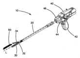
図1を参照すると、外科用ステープル留めシステムの一実施形態が示されている。図示の実施形態としての外科用ステープラ10は、細長いシャフト20、ジョー組立体30、及びハンドル組立体40を有する。図1は、ジョー組立体30が開き形態にある状態で外科用ステープラ10を示している。ステープル取替部50がジョー組立体内に位置決めされるのが良い。図示の外科用ステープル留めシステムは、電動ハンドルを備えた状態で示されているが、細長いシャフト20及びジョー組立体30を、機械式ステープラハンドルを含むステープル留めシステムに交換可能に使用できることが想定される。例えば、本明細書において説明する細長いシャフト組立体20及びジョー組立体30の種々の実施形態を2017年4月12日に出願され、現時点において係属中の米国特許出願第15/486,008号(発明の名称:SURGICAL STAPLER HAVING A POWERED HANDLE)に記載された電動ハンドル組立体か、2017年4月12日に出願され、現時点において係属中の米国特許出願第15/485,620号(発明の名称:SURGICAL STAPLER HAVING ARTICULATION MECHANISM)に記載された機械的手動式ハンドル組立体かのいずれかと交換可能に使用できることが想定される。これら特許出願を参照により引用し、これらの記載内容全体を本明細書の一部とする。 Referring to FIG. 1, one embodiment of a surgical stapling system is shown.
引き続き図1を参照すると、図示の実施形態としての外科用ステープラ10は、腹腔鏡外科的処置で使用できるよう寸法決めされるとともに形作られているのが良い。例えば、細長いシャフト20及びジョー組立体30は、アクセスポート又はトロカールカニューレを通って手術野中に導入されるよう寸法決めされるとともに形作られているのが良い。幾つかの実施形態では、細長いシャフト20及びジョー組立体30は、比較的小さな、例えば8mm未満の作業チャネル直径を備えたトロカールカニューレを通って挿入されるよう寸法決めされるとともに形作られているのが良い。他の実施形態では、細長いシャフト20及びジョー組立体30は、大きな、例えば10mm、11mm、12mm、又は15mmの作業チャネル直径を備えたトロカールカニューレを通って挿入されるよう寸法決めされるとともに形作られているのが良い。他の実施形態では、本明細書において説明する外科用ステープラのある特定の観点を開放外科的処置で使用可能な外科用ステープル留め器具中に組み込むことができることが想定される。 With continued reference to FIG. 1,
引き続き図1を参照すると、図示のように、細長いシャフト20は、全体として管状の部材を有する。細長いシャフト20は、近位端から遠位端まで延びている。細長いシャフト20は、近位端と遠位端との間に延びる外科用ステープラ10の長手方向中心軸線Lを定めている。 With continued reference to FIG. 1, as shown,
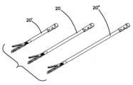
図2Aを参照すると、ステープル留めシステムは、所望の長さを備えた細長いシャフトを含むことが想定される。本明細書において説明するジョー組立体とハンドル結合部の特徴は、これらシャフト組立体の各々について実質的に同様であるのが良いが、シャフト本体は、スケール変更可能であるのが良い。例えば、ステープル留めシステムは、比較的短い細長いシャフト20′、中くらいの長さの細長いシャフト20、又は比較的長い細長いシャフト20″を含むことができる。これらシャフト長さの各々は、患者又は手技のサブセットについて特定の利用可能性を有することができる。例えば、短い細長いシャフト20′は、小児科手技で有用な場合があり、長い細長いシャフト20″は、肥満学的手技で有用な場合がある。 Referring to FIG. 2A, the stapling system is envisioned to include an elongated shaft with a desired length. The jaw assembly and handle coupling features described herein may be substantially similar for each of these shaft assemblies, but the shaft body may be scalable. For example, the stapling system may include a relatively short elongated shaft 20', a medium length
図2Bを参照すると、ステープル留めシステムは、所望の長さを備えたジョー組立体を含むことができるということが想定される。本明細書において説明するジョー組立体とハンドル結合部の特徴は、これらシャフト組立体の各々について実質的に同様であるのが良いが、シャフト本体は、スケール変更可能であるのが良い。例えば、ステープル留めシステムは、比較的短い細長いシャフト30′、中くらいの長さの細長いシャフト30、又は比較的長い細長いシャフト30″を含むことができる。これらシャフト長さの各々は、患者又は手技のサブセットについて特定の利用可能性を有することができる。ある特定の実施形態では、ジョー組立体は、約45mmの長さを有することが想定される。他の実施形態では、ジョー組立体は、約60mmの長さを有することが想定される。 Referring to FIG. 2B, it is envisioned that the stapling system can include jaw assemblies with desired lengths. The jaw assembly and handle coupling features described herein may be substantially similar for each of these shaft assemblies, but the shaft body may be scalable. For example, the stapling system may include a relatively short elongated shaft 30', a medium length
引き続き図1を参照すると、例示の実施形態では、ジョー組立体30は、細長いシャフト20の遠位端24のところで細長いシャフト20に結合されている。ジョー組立体は、第1のジョー32及び第1のジョー32に回動可能に結合された第2のジョー34を含む。図示の実施形態では、ジョー組立体30は、細長いシャフト20に対して関節運動可能である。 With continued reference to FIG. 1 , in the illustrated embodiment,
引き続き図1を参照すると、図示の実施形態では、ジョー組立体30を細長いシャフト内で長手方向に摺動可能な作動部材又はビームによって開き形態(図1)から閉じ形態に、すなわちステープル留め形態に作動させることができる。初期の位置では、ビームは、細長いシャフト20の遠位端24のところに位置決めされるのが良い。ビームが初期位置にある状態で、第2のジョー34を回動させて第1のジョー32から遠ざけてジョー組立体30が開き形態にあるようにする。作動ビームは、長手方向軸線Lに沿って遠位側への作動部材又はビームの並進時、第2のジョー34に係合する。作動ビームを初期位置から遠位側に第1の距離にわたって並進させると、ジョー組立体を開き形態から閉じ形態に作動させることができる。ジョー組立体30が閉じ形態にある状態で、作動ビームを近位側に第1の距離にわたって戻すと、ジョー組立体30を開き形態に戻すことができる。作動ビームの遠位端は、ステープルを第1のジョー32から展開するよう構成されたステープルスライダを前進させることができ、その結果、第1の距離を超えて作動ビームを遠位側に更に並進させると、複数のステープルが第1のジョー32内の取替部から展開されるようになる。 With continued reference to FIG. 1, in the illustrated embodiment,
引き続き図1を参照すると、図示の実施形態では、ハンドル組立体は、細長いシャフト20の近位端のところで細長いシャフト20に結合されている。図示のように、ハンドル組立体40は、静止ハンドル42及び静止ハンドル42に回動可能に結合された可動ハンドル44又はトリガを備えたハウジングを備えた拳銃握り形態を有する。他の実施形態では、本明細書において説明する観点を含む外科用ステープラ器具が他の形態、例えばはさみ握り形態又はインライン形態を備えたハンドル組立体を有しても良いことが想定される。以下に更に詳細に説明するように、ハンドル組立体40は、作動シャフトを可動ハンドル44の運動に応動して選択的に前進させるよう構成された作動機構体を収容している。 With continued reference to FIG. 1, in the illustrated embodiment, the handle assembly is coupled to elongate
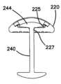
図3を参照すると、シャフト組立体20の遠位端のところに位置するジョー組立体の一実施形態が示されている。図示の実施形態では、ジョー組立体は、関節運動継手230のところでシャフト組立体20の遠位端に関節運動可能に結合された取替部支持体210を含む。アンビル220が取替部支持体210に回動可能に結合されており、このアンビルは、ジョー組立体30の上側ジョーを構成している。発射部材240がジョー組立体内で摺動して当初アンビル220を取替部支持体210に対して閉じ、次にステープルを取替部から発射することができる。幾つかの実施形態では、発射部材240は、垂直ビーム242が2つの水平に突き出たフランジ244,246相互間にまたいだ状態のIビーム形態を有する。有利には、Iビーム形態により、一方の水平フランジ244は、アンビル220に設けられたチャネルに嵌まり込むことができ、他方のフランジ246は、取替部又は取替部支持体に設けられたチャネルに嵌まり込むことができ、それによりジョー組立体を閉じ、次に発射部材が遠位側に送り進められたときにジョー組立体の所望の閉じ間隔を維持することができる。幾つかの実施形態では、発射部材240は、Iビーム形態の垂直ビーム上に形成され又はこれに取り付けられた切れ刃248を有するのが良い。この切れ刃は、ステープルが発射されているときに組織を分離することができ、それにより分離された組織の両面上にステープルラインを形成することができる。 Referring to FIG. 3, one embodiment of a jaw assembly located at the distal end of
図4及び図5を参照すると、取替部支持体210は、使い捨て取替部50を受け入れてこれを保持するよう寸法決めされているのが良い。取替部50を下降させるとともに取替部支持体210中に近位側に動かすことができ、ついには、取替部に設けられている嵌め合わせ特徴部が取替部支持体210に設けられている対応の特徴部に係合するようになる。 4 and 5, refill
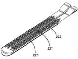
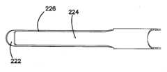
図6A、図6B、図7、及び図8を参照すると、ジョー組立体30のアンビル220の種々の観点が示されている。ある特定の実施形態では、アンビル220は、頂面224に結合されたアンビルプレート222を有する。アンビルプレートは、このアンビルプレートに形成されていて発射部材の水平フランジが嵌まり込む長手方向チャネル225及び長手方向チャネル225を貫通して形成されていて発射部材の垂直ビームが嵌まり込む長手方向スロット227を有するのが良い。頂面224は、後でアンビルプレートの上に位置するよう成形される材料のシートで作られるのが良い。(図8は、扁平なシート2224′及び成形された頂面224を示している)。有利には、アンビルプレート222への頂面224の追加により、ジョー組立体のアンビルの強度が増す。 6A, 6B, 7 and 8, various views of
図9及び図10を参照すると、ジョー組立体30のアンビルプレート222の種々の観点が示されている。アンビルプレート上には複数のステープル成形ポケット223が設けられている。図示の実施形態では、ステープル成形ポケット223は、3つの列から成る2つのアレイの状態で位置決めされ、これらアレイは、発射部材のためのスロットの各側に位置決めされている。かくして、ステープラは、2つの組をなすステープルの3つの直線状列を形成することができ、これら組は、分割された組織で互いに隔てられている。他の実施形態では、アンビルは、ステープルの他の個数及び形態を成形するよう構成されたステープル成形ポケットを有しても良いことが想定される。ステープル成形ポケットは、テーパ付き形態を有し、比較的大きなステープル導入側が比較的小さなステープル成形側まで細まっている。有利には、このテーパ付き形態は、ステープルを案内して成形を完了させるとともに成形度の貧弱なステープルの発生率を減少させることができる。隣り合うステープル列は、互いに長手方向にオフセットしているのが良く、その結果、列の全ての比較的広い導入側は、ステープル列の組の全幅を減少させるよう互いにオフセットしている。 9 and 10, various views of
図11A及び図11Bを参照すると、アンビル220のある特定の実施形態では、頂面224は、溶接線226に沿う溶接作業によってアンビルプレート222に結合されるのが良い。有利には、溶接作業によって形成されたこの閉じ状態のアンビルは、発射部材のためのチャネルを覆う。 11A and 11B, in one particular embodiment of
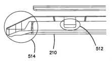
図12及び図13を参照すると、取替部支持体210中への取替部50の挿入の仕方が示されている。取替部支持体は、取替部支持体210の側壁からその近位端に隣接して半径方向内方に突き出た近位ジョータブ212を有するのが良い。取替部は、近位ジョータブの下に位置決めされるとともにこれらによって保持されるよう寸法決めされた比較的短いテーパ付き近位デッキ510を有するのが良い。さらに、取替部50は、その遠位端に隣接して側方外方に突き出た保持タブ512を有するのが良い。取替部支持体210は、これに対応した対をなす保持凹部214を有するのが良く、これら保持凹部は、取替部が取替部支持体内に位置決めされると、保持タブを受け入れるよう寸法決めされるとともに形作られている。 12 and 13, the insertion of
図14及び図15を参照すると、Iビーム形態を有する発射部材240の一実施形態が示されている。図示の実施形態では、発射部材は、前縁のところに切れ刃が形成された垂直ビーム242を有する。切れ刃は、湾曲した切れ刃248から成る。発射部材240の後縁は、発射部材を細長いシャフトを貫通した駆動部材にしっかりと結合することができるようにする駆動部材インターフェース245、例えば切欠き又は突出部を有する。発射部材240の後縁は、発射部材が近位側の位置にあるとき、取替部ロックアウトをロック解除形態で位置決めすることができるロックアウトインターフェース247、例えば近位側に延びる「テール」を更に有するのが良い。発射部材は、アンビルのチャネル225内に嵌まり込むよう構成された上側水平フランジ244及び取替部又は取替部支持体に係合するよう構成された下側水平フランジ246を更に有する。図15に示されているように、発射部材は、全体としてIビーム形態を有するが、幾つかの実施形態では、水平フランジは、アンビルのチャネル225の形状に合うよう湾曲していてもよく又はテーパ付けされていても良い。幾つかの実施形態では、発射部材240は、更に例えば表面仕上げ作業、フィルム潤滑剤の添加、又は発射部材、チャネル、又はこれら両方上への低摩擦面の被着によって発射シーケンス中に摩擦を減少させるよう構成されているのが良い。 14 and 15, one embodiment of firing
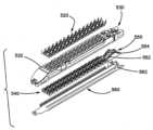
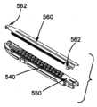
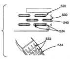
図16~図19を参照すると、ステープル留めシステムに用いられる取替部50の一実施形態が示されている。取替部50は、複数のステープル520を有し、これらステープル520は、カートリッジ530に形成された対応の複数のステープルポケット532内に位置決めされている。ステープルポケット532は、それぞれ3つの列の2つの組の状態に配列され、各組は、カートリッジ530を貫通して形成されたスロットだけ隔てられている。ステープル520は、ステープルポケット532の下に位置する複数のステープルプッシャ540内に嵌まっている。ステープルプッシャ540の各列に対応したランプ又は傾斜路552及びロックアウトレール554を備えたスライダ550が取替部の近位端のところに位置決めされている。スライダ550は、発射部材の運動に応動して取替部内で長手方向に摺動可能である。ジャケット560がカートリッジの下に位置し、このジャケットは、ステープル及びステープルプッシャをステープルポケット内に維持する。ジャケットは、カートリッジに係合する突き出しフック562を有するのが良い。 16-19, one embodiment of a reload 50 for use with a stapling system is shown. Reload 50 has a plurality of
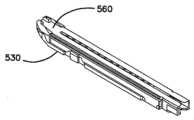
図20を参照すると、幾つかの実施形態では、取替部50は、カートリッジの上面を覆う輸送用カバー570を有するのが良い。有利には、輸送用カバー570は、取替部が用いられる前にステープルのうちの1つ又は2つ以上がステープルポケットから脱落状態になり又は位置合わせ不良状態になるのを阻止することができる。輸送用カバー570は、取替部50が取替部支持体内に位置決めされる前に取り外される。 Referring to FIG. 20, in some embodiments the
図21~図23を参照すると、幾つかの実施形態では、取替部50は、ある特定のステープル位置合わせ部及び保持特徴部を有するのが良い。例えば、カートリッジ530に形成されたステープルポケット532は、その端部のところに設けられていてカートリッジ内に位置決めされたステープル520のレッグを受け入れるステープル案内534を有するのが良い。ステープルプッシャ540は、ステープル案内534の中に乗るよう寸法決めされるとともに形作られたナブ542を更に有するのが良い。図示のように、ある特定の実施形態では、ステープルプッシャ540は、3つの群をなして成形されるのが良く、その結果、1つのステープルプッシャ540は、3つの隣り合うステープル列の各々に属する単一のステープルを押すことができるようになっている。さらに、ステープルプッシャ540の各々の上面544は、ステープルを比較的確実に受け入れるステープルサドル形態を有するのが良い。ステープル520をステープルプッシャ540内にしっかりと位置決めするとともにステープルレッグ及びステープルプッシャのナブ542をステープル案内と係合させることにより、有利には、位置合わせ不良又は成形不良のステープルの発生率を減少させることができる。 21-23, in some embodiments, reload 50 may have certain staple alignment and retention features. For example, staple pockets 532 formed in
図24~図31を参照すると、種々の実施形態では、取替部50とジョー組立体は、取替部50のステープルポケットをアンビルのステープルの成形ポケットと位置合わせしてステープル発射中、ジョー組立体内における取替部50の位置を維持するよう互いにしっかりと結合されるよう構成されているのが良い。取替部50は、その近位端のところに設けられた情報に突き出ているボス538を有するのが良く(図24)、これら上方に突き出たボス538は、ジョー組立体が閉じ形態にある状態で、アンビル220と取替部50のカートリッジ530の上面との間に組織隙間を作る(図25)。さらに、取替部の遠位端に隣接して形成された保持タブ512(図26)は、取替部支持体210の凹部214内に位置決めされて取替部が発射作業中に遠位側にずれるのを阻止する。かくして、取替部50を迅速かつ確実に取替部支持体210に結合することができる(図28及び図29)。加うるに、カートリッジ530の近位端部は、取替部支持体上への配置を一段と容易にするよう減少高さまでテーパしているのが良い(図30)。さらに、カートリッジは、低くなっていく遠位端部514が取替部支持体の下に突き出た輪郭形状を有する状態で較正されるのが良い(図31)。この低プロフィールは、取替部と取替部支持体との確実な係合を保証する。 Referring to FIGS. 24-31, in various embodiments, the reload 50 and jaw assembly are aligned during staple firing with the staple pockets of the reload 50 aligned with the staple forming pockets of the anvil. It may be configured to be rigidly coupled together to maintain the position of the
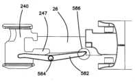
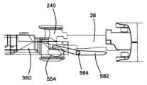
図32A、図32B、並びに図33及び図34を参照すると、ある特定の実施形態では、ジョー組立体は、取替部ロックアウト機構体580を含むのが良い。取替部ロックアウト機構体580は、ジョー組立体内に位置決めされている取替部がない場合又は空の取替部がジョー組立体内に位置決めされている場合、発射部材の前進を阻止することができる。取替部ロックアウト機構体580は、取替部支持体に回動可能に結合されたロックアウトレバー582を含む。このピボットにより定められた軸線は、細長いシャフトの長手方向軸線に対して全体として横方向に延びる。発射部材240が完全に引っ込められてジョー組立体が開き形態にある状態で、発射部材240から近位側に突き出ているテール247がロックアウトレバー582をロック解除位置にピボット動作された状態に維持する。図示の実施形態では、ピボットの近位側に位置するロックアウトレバー582の近位の部分は、発射部材240を受け入れるようフォーク状又は二股状であり、その結果、テール247は、ピボットの遠位側に位置するロックアウトレバー582の表面に作用することができるようになっている。挿入されている取替部がない場合、発射部材240を前進させようとすると、ロックアウトレバーは、発射部材のテール247がロックアウトレバーに沿って遠位側に送り進められているときにロック解除位置からロック位置にピボット箇所584回りに回動することができる(図33)。ロックアウトレバー582がロック位置にある状態で、ロックアウトレバーの近位側のロック端部586は、駆動部材26に設けられているロック凹部に当たり、それにより駆動部材のそれ以上の遠位側への運動を阻止する。 32A, 32B, and 33-34, in certain embodiments, the jaw assembly can include a reload
図32A、図32B、並びに図33及び図34を引き続き参照すると、未発射状態の取替部が取替部支持体中に挿入された場合(図34)、スライダ550から近位側に延びているテール554がロックアウトレバー582の遠位端に係合する。図示のように、テール554は、ピボット箇所の遠位側に位置するロックアウトレバー582の遠位部分の下面に作用する。スライダテール554とロックアウトレバー582の遠位端部とのこの係合により、発射部材240のテール247がいったんもはやロックアウトレバー582の近位部分に作用していない場合であってもロックアウトレバー582の遠位端部が回動して駆動部材26から遠ざかる。したがって、駆動部材26及び発射部材240を遠位側に前進させてステープルを取替部から発射することができる。発射ストロークの完了時、スライダ550は、取替部の遠位端部のところに留まる。かくして、ジョー組立体を開き形態に戻して発射部材を引っ込めた場合、発射後の取替部は、取り外されるべきであり、そして新たな未発射状態の取替部が取替部ロックアウトをロック解除するよう挿入されるべきである。 With continued reference to FIGS. 32A, 32B, and 33 and 34, when the unfired reload is inserted into the reload support (FIG. 34), the
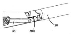
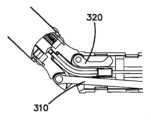
図35~図37を参照すると、ジョー組立体30を細長いシャフト20の遠位端に結合するための関節運動継手300の一実施形態が示されている。図示の実施形態では、関節運動継手300は、シャフト組立体の長手方向中心軸線から側方にオフセットした状態でジョー組立体に回動可能に結合された関節運動ロッド310を有する。ピボット箇所が長手方向中心軸線に沿って位置決めされている。関節運動継手300は、シャフトの長手方向中心軸線から側方にオフセットするとともに関節運動ロッドと反対側でジョー組立体に回動可能に結合された支持リンク320を更に有する。駆動ビーム26は、関節運動ロッド310と支持リンク320との間で長手方向中心軸線に沿って長手方向に延びている。少なくとも、関節運動継手300を貫通した駆動ビーム26のセグメントは、可撓性である。幾つかの実施形態では、駆動ビーム26は、シム材料のスタックから成る可撓性セグメントに結合されるのが良く、この可撓性セグメントは、ステープル発射作業のための所望の力伝達能力を維持しながら可撓性である。関節運動継手は、駆動ビーム26の側方外方に位置決めされた1つ又は2つ以上の駆動部材支承体330を更に有するのが良い。幾つかの実施形態では、駆動支承体330は、軟質プラスチック材料から成るのが良い(図36)。他の実施形態では、駆動支承体330′は、金属シム材料で構成されるのが良い(図37)。有利には、金属シム駆動支承体330′は、駆動部材の可撓性セグメントに対して支持作用を提供するようシャフト中にキー止めされるのが良い。さらに、金属シム支承体は、比較的低プロフィールの形態を有することができる。金属シム支承体は、発射中における摩擦を減少させるために低摩擦被膜、例えばTEFLON(登録商標)被膜を有するのが良い。 35-37, one embodiment of an articulation joint 300 for coupling
図38A及び図38Bを参照すると、ジョー組立体を第1の関節運動位置及び第2の関節運動位置に位置決めするための関節運動継手の関節連結の仕方が示されている。関節運動ロッド310をシャフトに対して近位側に(図38A)又は遠位側に(図38B)に並進させることができる。関節運動ロッド310の側方オフセット位置決めにより、ジョー組立体は、関節運動ロッドの並進に応動してシャフトに対して関節運動する。関節運動ロッド310と反対側の支持リンク320は、受動的であるが、ジョー組立体の関節運動を案内することができ、しかも有利には、駆動ビーム26の可撓性部分を関節運動継手のところでシャフトの中心寄りに維持するのを助けることができ、それにより駆動ビーム26の可撓性部分が関節運動継手のところの関節運動曲げ部のところで座屈するのを阻止する。他の実施形態では、関節運動継手は、関節運動ロッド及び支持リンクに代えて、2つの関節運動ロッドを有することができる。2つの関節運動ロッドを備えた実施形態では、関節運動ラッチ機構体がシャフト内に位置決めされるのが良く、それによりステープル発射作業がいったん開始すると、望ましくない関節運動を阻止することができる。例えば、ラッチ又はブレーキ機構体は、駆動ビーム26が遠位側にいったん並進されると、関節運動ロッドがそれ以上の運動を行わないよう保持することができる。 Referring to Figures 38A and 38B, there is shown how the articulation joints are articulated to position the jaw assemblies in the first and second articulation positions. The
図39及び図40を参照すると、ジョー組立体30を細長いシャフト20の遠位端に結合する関節運動継手300′の別の実施形態が示されている。関節運動継手300′は、細長いシャフト内に位置決めされた関節運動ラッチ機構体340を有する。図示の実施形態では、関節運動継手300′は、関節運動継手300′は、シャフト組立体の長手方向中心軸線から側方にオフセットした状態でジョー組立体に回動可能に結合された関節運動ロッド310′を有する。ピボット箇所が長手方向中心軸線に沿って位置決めされている。関節運動継手300′は、シャフトの長手方向中心軸線から側方にオフセットした状態でかつ関節運動ロッドと反対側でジョー組立体に回動可能に結合された支持リンク320′を更に有する。駆動ビーム26′は、関節運動ロッド310′と支持リンク320′との間で長手方向中心軸線に沿って長手方向に延びている。少なくとも、関節運動継手300′を貫通した駆動ビーム26′のセグメントは、可撓性である。幾つかの実施形態では、駆動ビーム26′は、シム材料のスタックから成る可撓性セグメントに結合されるのが良く、この可撓性セグメントは、ステープル発射作業のための所望の力伝達能力を維持しながら可撓性である。関節運動継手は、駆動ビーム26′の側方外方に位置決めされた1つ又は2つ以上の駆動部材支承体330を更に有するのが良い。幾つかの実施形態では、駆動支承体330は、軟質プラスチック材料から成るのが良い(図36)。他の実施形態では、駆動支承体330′は、金属シム材料で構成されるのが良い(図37)。有利には、金属シム駆動支承体330′は、駆動部材の可撓性セグメントに対して支持作用を提供するようシャフト中にキー止めされるのが良い。さらに、金属シム支承体は、比較的低プロフィールの形態を有することができる。金属シム支承体は、発射中における摩擦を減少させるために低摩擦被膜、例えばTEFLON(登録商標)被膜を有するのが良い。 39 and 40, another embodiment of articulation joint 300'
図41及び図42を参照すると、ジョー組立体を第1の関節運動位置及び第2の関節運動位置に位置決めするための関節運動継手の関節連結の仕方が示されている。関節運動ロッド310′をシャフトに対して近位側に(図41)又は遠位側に(図42)に並進させることができる。関節運動ロッド310′の側方オフセット位置決めにより、ジョー組立体は、関節運動ロッドの並進に応動してシャフトに対して関節運動する。関節運動ロッド310′と反対側の支持リンク320′は、受動的であるが、ジョー組立体の関節運動を案内することができ、しかも有利には、駆動ビーム26′の可撓性部分を関節運動継手のところでシャフトの中心寄りに維持するのを助けることができ、それにより駆動ビーム26′の可撓性部分が関節運動継手のところの関節運動曲げ部のところで座屈するのを阻止する。他の実施形態では、関節運動継手は、関節運動ロッド及び支持リンクに代えて、2つの関節運動ロッドを有することができる。 41 and 42, there is shown how the articulation joints are articulated to position the jaw assemblies in the first and second articulation positions. The articulation rod 310' can be translated proximally (Fig. 41) or distally (Fig. 42) relative to the shaft. The lateral offset positioning of articulation rod 310' causes the jaw assembly to articulate with respect to the shaft in response to translation of the articulation rod. The support link 320' opposite the articulation rod 310' is passive but can guide the articulation of the jaw assembly and advantageously articulate the flexible portion of the drive beam 26'. It can help keep the shaft centered at the kinematic joints, thereby preventing the flexible portion of the drive beam 26' from buckling at the articulation bends at the articulation joints. In other embodiments, the articulation joint can have two articulation rods instead of the articulation rod and the support link.
図39~図43を参照すると、関節運動継手300′の関節運動ラッチ機構体340又はブレーキ機構体は、駆動ビーム26′が遠位側にいったん並進されると、関節運動ロッド及び支持リンクがそれ以上の運動を行わないよう保持することができる。図示の実施形態では、ラッチ機構体340は、細長いシャフトの近位端と遠位端との間で細長いシャフト内に位置決めされている。関節運動ラッチ留め機構体340は、関節運動ロッド及び支持リンクが細長いシャフト内で摺動可能なラッチ解除形態を有する。かくして、関節運動ラッチ留め機構体がラッチ解除形態にある状態では、ユーザは、ハンドル組立体に設けられている関節運動制御部の操作によってジョー組立体を細長いシャフトに対して関節運動させることができる。関節運動ラッチ留め機構体340は、関節運動ラッチ留め機構体が関節運動ロッド及び支持リンクに係合して細長いシャフトに対する関節運動リンク及び支持リンクの長手方向摺動を阻止するラッチ留め形態(図43)を更に有する。かくして、ラッチ留め形態では、ジョー組立体は、関節運動後の位置に保持され、ユーザは、ジョー組立体を細長いシャフトに対して関節運動させることができないようになる。 39-43, the articulation latch mechanism 340 or brake mechanism of the articulation joint 300' ensures that once the drive beam 26' is translated distally, the articulation rods and support links engage it. It can be held without doing any of the above exercises. In the illustrated embodiment, the latch mechanism 340 is positioned within the elongate shaft between the proximal and distal ends of the elongate shaft. Articulation latching mechanism 340 has an unlatching configuration in which the articulation rod and support links are slidable within the elongated shaft. Thus, with the articulation latching mechanism in the unlatched configuration, the user can articulate the jaw assembly relative to the elongated shaft by manipulation of the articulation controls provided on the handle assembly. . The articulation latching mechanism 340 has a latching configuration in which the articulation latching mechanism engages the articulation rod and the support links to prevent longitudinal sliding of the articulation links and the support links relative to the elongated shaft (Fig. 43). ). Thus, in the latched configuration, the jaw assemblies are held in a post-articulation position such that the user cannot articulate the jaw assemblies relative to the elongated shaft.
引き続き図39~図43を参照すると、図示の実施形態では、関節運動ラッチ留め機構体340は、関節運動ロッド310′上に形成された第1のラッチ表面、例えば第1の複数の歯342を含む。図示のように、第1の複数の歯342は、関節運動ロッド310′の近位端と遠位端との間で細長いシャフト内に位置決めされている。間接運ドルラッチ留め機構体340は、支持リンク320′上に形成された第2のラッチ表面、例えば第2の複数の歯344を更に有するのが良い。図示のように、ラッチ留め関節運動機構体を含む細長いシャフト組立体の実施形態では、支持リンク320′は、関節運動ラッチ留め機構体340を貫通してシャフト内で近位側に延びるのが良い。図示の実施形態では、第2の複数の歯344は、支持リンク320′の近位端に隣接して支持リンクの近位端と支持リンクの遠位端との間に位置決めされている。 With continued reference to FIGS. 39-43, in the illustrated embodiment, articulation latching mechanism 340 includes a first latching surface, such as a first plurality of teeth 342, formed on
図示の実施形態では、関節運動ラッチ留め機構体340は、第1のシュー346を更に含み、この第1のシュー上には嵌合面、例えば第1の爪表面348が形成されている。第1の爪表面348は、第1の複数の歯342と係合可能であるように寸法決めされるとともに形作られている。第1のシュー346は、嵌合面と反対側に展開面を有するのが良く、展開面は、駆動ビーム26′と摺動係合関係をなしている。関節運動ラッチ留め機構体340は、第2のシュー350を更に含み、この第1のシュー上には嵌合面、例えば第2の爪表面352が形成されている。第2の爪表面352は、第2の複数の歯344と係合可能であるように寸法決めされるとともに形作られている。第2のシュー350は、嵌合面と反対側に展開面を有するのが良く、展開面は、駆動ビーム26′と摺動係合関係をなしている。関節運動ラッチ留め機構体340は、駆動ビーム26′の近位端と遠位端との間で駆動ビーム26′上に形成されるとともに細長いシャフト内に位置決めされたラッチ留め輪郭形状を更に含むのが良い。図示の実施形態では、駆動ビーム26′は、これに形成された凹部セグメント360、凹部セグメントの近位側に位置するテーパ付き又は傾斜セグメント362、及び傾斜セグメントの近位側に位置したラッチ留めセグメント364を有する。凹部セグメント360は、細長いシャフトの長手方向軸線に全体として垂直な方向に第1の幅を有し、ラッチ留めセグメント364は、第1の幅よりも大きな第2の幅を有する。関節運動ラッチ留め機構体は、第1及び第2のシューに結合されるとともにシュー346,350を付勢してこれらを第1及び第2の複数の歯342,344から離脱させる付勢部材、例えばばねクリップ370を更に含むのが良い。ばねクリップはまた、シュー346,350の展開面と駆動ビーム26′のラッチ留め輪郭形状の係合状態を維持することができる。 In the illustrated embodiment, the articulation latching mechanism 340 further includes a first shoe 346 having a mating surface, eg, a first pawl surface 348 formed thereon. First pawl surface 348 is sized and shaped to be engageable with first plurality of teeth 342 . The first shoe 346 may have a deployment surface opposite the mating surface, the deployment surface being in sliding engagement with the drive beam 26'. Articulation latching mechanism 340 further includes a second shoe 350 having a mating surface, eg, a second pawl surface 352 formed thereon. Second pawl surface 352 is sized and shaped to be engageable with second plurality of teeth 344 . The second shoe 350 may have a deployment surface opposite the mating surface, the deployment surface being in sliding engagement with the drive beam 26'. Articulation latching mechanism 340 further includes a latching profile formed on drive beam 26' between the proximal and distal ends of drive beam 26' and positioned within the elongated shaft. is good. In the illustrated embodiment, the drive beam 26' has a recessed segment 360 formed therein, a tapered or angled segment 362 located proximally of the recessed segment, and a latching segment located proximally of the angled segment. 364. Recessed segment 360 has a first width in a direction generally perpendicular to the longitudinal axis of the elongated shaft, and latching segment 364 has a second width that is greater than the first width. an articulation latching mechanism is a biasing member coupled to the first and second shoes and biasing the shoes 346,350 away from the first and second plurality of teeth 342,344; For example, a spring clip 370 may also be included. The spring clip can also maintain the engagement of the deployment surfaces of the shoes 346, 350 and the latching profile of the drive beam 26'.
引き続き図39~図43を参照すると、作用において、関節運動ラッチ留め機構体340を当初、ラッチ解除形態(図39~図42)に位置決めするのが良く、その結果ジョー組立体を細長いシャフトに対して所望の配向状態に関節運動させることができる。この初期位置決めの際、駆動ビーム26′は、ジョー組立体の開き又は部分閉じ形態に対応した細長いシャフトに対する近位側の位置にある。ラッチ解除形態では、第1及び第2のシュー346,350は、半径方向内方の位置で駆動ビーム26′の凹部セグメント360に隣接して位置決めされる。ジョー組立体の所望の関節運動後の位置がいったん選択されると、ユーザは、引き続きジョー組立体を閉じてジョー組立体を発火することができ、その結果、細長いシャフトに対する駆動ビーム26′の遠位側への作動が生じる。駆動ビーム26′のこの遠位側への運動により、傾斜及びラッチ留めセグメント362,364が第1及び第2のシュー346,350の展開面上を前進してこれらシューを半径方向外方に前進させる(図43)。第1及び第2のシュー346,350が半径方向外方の形態にある状態で、第1の爪表面348は、第1の複数の歯342に係合し、第2の爪表面352は、第2の複数の歯344に係合し、それにより関節運動ラッチ機構体をラッチ留め形態に構成する。発射シーケンス後にジョー組立体を開くことにより、この順序が逆になって関節運動ラッチがラッチ解除形態に戻る。かくして、望ましくは、駆動部材26′を作動させてジョー組立体を閉じてこれを発火させることにより、ジョー組立体の関節運動後の位置が自動的にラッチ留めされる。有利には、このラッチ留めは、駆動ビームを関節運動曲げ部周りに前進させたりこれを通って引っ込めたりしているときにジョーが細長いシャフトに対して「振る」傾向を減少させ又は阻止することができる。関節運動ラッチ留め機構体の図示の実施形態は、周囲に設けられた歯の噛み合いアレイ並びに複数の別々のラッチ留め位置を定める関節運動ロッド及び支持リンクを含むが、他の実施形態では、シュー、関節運動ロッド、及び支持リンクは、ラッチ留め関節運動位置の連続アレイを定めるよう互いに摩擦的に係合するよう構成されても良いことが想定される。さらに、図示の実施形態は、各々が対応の複数の歯と係合可能な2つのシューを含むが、他の実施形態では、単一のシューが関節運動ロッド又は支持リンクに設けられた単一種類の複数の歯に係合するよう前進可能であっても良い。 With continued reference to FIGS. 39-43, in operation the articulation latching mechanism 340 can be initially positioned in the unlatched configuration (FIGS. 39-42), thereby moving the jaw assembly relative to the elongated shaft. can be articulated to the desired orientation. During this initial positioning, the drive beam 26' is in a proximal position relative to the elongated shaft corresponding to the open or partially closed configuration of the jaw assembly. In the unlatched configuration, first and second shoes 346, 350 are positioned adjacent recessed segment 360 of drive beam 26' at a radially inward position. Once the desired post-articulation position of the jaw assembly has been selected, the user can continue to close the jaw assembly to fire the jaw assembly, thereby moving the drive beam 26' farther relative to the elongated shaft. Actuation to the posterior side occurs. This distal movement of drive beam 26' advances ramp and latching segments 362, 364 over the deployment surfaces of first and second shoes 346, 350 to advance them radially outwardly. (Fig. 43). With the first and second shoes 346, 350 in the radially outward configuration, the first pawl surface 348 engages the first plurality of teeth 342 and the second pawl surface 352: The second plurality of teeth 344 are engaged thereby configuring the articulation latch mechanism in the latched configuration. Opening the jaw assemblies after the firing sequence reverses this sequence and returns the articulation latches to the unlatched configuration. Thus, desirably, the articulated position of the jaw assemblies is automatically latched by actuating the drive member 26' to close and fire the jaw assemblies. Advantageously, this latching reduces or prevents the tendency of the jaws to "swing" relative to the elongated shaft as the drive beam is being advanced around and retracted through the articulation bend. can be done. Although the illustrated embodiment of the articulation latching mechanism includes an articulation rod and support link defining a plurality of discrete latching positions as well as a meshing array of teeth disposed around the periphery, other embodiments may include a shoe, It is envisioned that the articulation rods and support links may be configured to frictionally engage one another to define a continuous array of latching articulation positions. Further, while the illustrated embodiment includes two shoes each engageable with a corresponding plurality of teeth, in other embodiments a single shoe is provided on the articulation rod or support link. It may be advanceable to engage multiple teeth of a type.
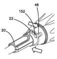
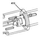
図44及び図45A~図45Dを参照すると、ハンドル組立体40の遠位端のところに設けられたカップラ46がシャフト組立体20の近位端に結合されるのが良い。カップラ46は、ロックインを備えた差込み形連結部を有するのが良い。図示の実施形態では、取替式シャフト20とハンドル40の連結部は、差込み形連結部から成り、この差込み形連結部では、ユーザが取替式シャフト20をハンドル40中に軸方向に整列させて挿入し、そして取替式シャフト20を約90°回転させて連結する。この差込み形連結部は、差込み形シャフト20の2つの機械的機能をハンドル40の対応のアクチュエータに作動的に結合する。差込み形連結部を完全に結合すると、シャフト20内の関節運動部材がハンドルの関節運動アダプタに結合され、シャフト20内の駆動部材が作動アダプタに結合される。さらに、ハンドル40及びシャフト20は、作動アダプタ及び駆動部材がいったん作動されると、ユーザがシャフト20を取り外すのを阻止するためにカップラ46のところに設けられたラッチ機構体を備えた状態で構成されるのが良い。さらに、カップラ46のところの接続部は、ハンドルの制御システムが取替式シャフトを連結したかどうか及びそこで取替部の取り付け状態のジョー長さがどれほどのものかを検出することができるよう取替部識別機構体を有するのが良い。種々の長さのジョー機構体を含む取替式シャフト20とともにハンドルを用いることができるということが想定される。幾つかの実施形態では、同一のハンドル40を45mm長さか60mm長さかのいずれかのジョー組立体にともに使用できる。 44 and 45A-45D, a
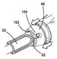
図45Aでは、シャフト20は、ハンドルに設けられたカップラ46と並列状態に位置決めされ、カップラ46の解除ノブがカップラ46の回転挿入時にカップラ46の差込み形チャネル152を露出させるよう引っ込められる。シャフト20は、差込み形チャネル152内に位置決め可能な保持ポスト22又はボスを有するのが良い。図示の実施形態では、シャフトは、その外面上に180°間隔で位置決めされた2つのボスを有し、カップラ46は、これらに対応した2つの差込み形チャネル152を有する。他の実施形態では、ボス及び差込み形チャネルの他の数及び形態を用いて所望の連結強度及び整列しやすくすることができることが想定される。 45A, the
図45Bを参照すると、シャフトの保持ポスト22は、差込み形チャネル152内に位置決めされている。図45Cを参照すると、取替式シャフト20は、ハンドルに対して90°回されており、その結果、シャフトの保持シャフト22は、差込み形チャネル152の連結端部に達している。図45Dを参照すると、カップラの解除ノブは、解除ノブに設けられている保持凹部154が取替式シャフト20の保持ポスト22を保持することができるよう解除されている。 Referring to FIG. 45B,
図46及び図47を参照すると、シャフト組立体は、管状シャフトを含むのが良く、駆動部材又は駆動ビーム26及び関節運動部材206は、この管状シャフトを貫通して近位端から遠位端まで延びている。駆動部材は、シャフト組立体の全体として中央を貫通するのが良く、これに対し、関節運動部材は、側方にオフセットしている。管状シャフトの近位端は、ハンドルの遠位端のところでカップラ46に結合可能な結合カラー410を有するのが良い。図示の実施形態では、シャフト組立体は、近位シャフト「ロックアウト」機構体を含むのが良い。ロックアウト機構体は、細長いシャフトの近位端のところに設けられたシャフトカップラ内に位置決めされたロックリング及び結合カラー410を貫通して半径方向外方に前進できる少なくとも1つのロックアウト部材を含む。ロックアウト部材は、半径方向外方に付勢可能であるが、初期位置ではロックリングによって半径方向内方の位置に保持される。シャフトの近位端が差込み形連結部に対応した回転シーケンスでハンドル組立体に結合されると、ロックリングは、ハンドル組立体に設けられた嵌合面に係合して細長いシャフトに対して回転する。ロックリングのこの回転により、ロックアウト部材が解除される。ハンドル組立体からのシャフトの取り外し時、ロックアウト部材は、半径方向に拡張する。この拡張位置では、ロックアウト部材は、ハンドル組立体への細長い部材の再結合を妨害する。かくして、このロックアウト機構体は、細長いシャフト組立体の不用意な再使用を制限するのに役立ちうる。 46 and 47, the shaft assembly may include a tubular shaft through which the drive member or drive
図48A及び図48Bを参照すると、シャフト組立体とハンドルとの間の差込み形連結部の係合状態が示されている。ハンドルのカップラは、結合カラー410に結合可能な回転スリーブを有するのが良く、作動アダプタ124、関節運動アダプタ204、及び識別スリーブ208がこの回転スリーブ内に位置決めされている。差込み結合中、シャフト26の駆動部材は、作動アダプタ124に係合し、シャフトの関節運動部材206は、関節運動アダプタ204に係合し、シャフト識別体が識別スリーブ208に係合する。図49A及び図49Bは、結合形態でのシャフトとのそれぞれの結合状態を示している。 Referring to Figures 48A and 48B, the engagement of the bayonet type connection between the shaft assembly and the handle is shown. The handle coupler may have a rotating sleeve couplable to the
図50及び図51を参照すると、図46及び図47を参照して説明したロックアウト機構体に代えて又はこれに加えて、細長いシャフトのある特定の実施形態は、作動アダプタ124の初期の遠位側への前進時に作動するロックイン又は保持機構体を含むのが良い。図示のように、ロック部材24がシャフト20の近位端部に回動可能に結合されている。ロック部材24は、その近位縁部のところに傾斜し又はテーパしたロック面を有するのが良い。図50に示されているように、シャフト20は、カップラ46に対して結合されているが非ロック形態をしている。結合非ロック形態では、シャフト20を図45A~図45Dの動作の順序を逆にすることにより差込み連結部を介してカップラ46から取り外すことができる。作動アダプタ124がステープラを作動させるよういったん前進すると、作動アダプタ124は、ロック部材24の傾斜面と相互作用してロック部材を半径方向外方に前進させてロック位置に至らせる。ロック位置(図51)では、ロック部材24は、シャフト内にロックインするようカップラ46に設けられているロック棚状突起に係合する。シャフト20がハンドル40に対してロックインされた状態では、作動アダプタ124が完全に近位側に引っ込められた位置(代表的には、ジョー組立体の完全閉鎖及びステープル留めサイクルに続くジョー開き形態への戻りに対応している)に戻るまでシャフト20をハンドル40から取り外すことができない。 50 and 51, alternatively or in addition to the lockout mechanism described with reference to FIGS. A lock-in or retention mechanism may be included that is activated during posterior advancement. As shown, a locking
かくして、「ロックイン」特徴は、駆動部材26をいったん前方に駆動すると、ユーザがシャフトをハンドルから取り外すのを阻止する。ロック部材24をカップラ46の回転インサートのスロット又は棚状突起内にいったん位置させると、カップラ46の解除ノブを引き戻すことができない。カップラに対するこのロック作用は、ユーザがシャフト20を回転させてこれをカップラ46の差込み連結部から出すのを阻止する。 Thus, the "lock-in" feature prevents the user from removing the shaft from the handle once the
図52を参照すると、シャフト組立体の近位端は、管状シャフトの近位端に設けられたシャフトカップラ又は結合カラー410を有する。かくして、本明細書において説明したステープル留めシステムは、種々の直径を有するシャフト組立体に使用できるよう容易に改造可能である。幾つかの実施形態では、シャフトカップラの内径は、種々の直径のシャフト組立体に対応するために互いに異なるハンドル組立体を必要としないで、種々の管状シャフトに対応するよう容易にサイズ変更可能である。 Referring to Figure 52, the proximal end of the shaft assembly has a shaft coupler or
本願は、ある特定の好ましい実施形態及び実施例を開示しているが、当業者であれば理解されるように、本発明は、具体的に開示した実施形態を超えて他の変形実施形態及び/又は本発明の使用並びに明白な改造及びその均等範囲に及ぶ。さらに、これら発明の種々の特徴を単独で又は明示的に上述した特徴以外のこれら発明の他の特徴と組み合わせて使用できる。かくして、本明細書において開示した本発明の範囲は、上述の特定の開示した実施形態によって限定されるべきではなく、特許請求の範囲の公平な解釈によってのみ定められるべきであることが意図されている。 Although this application discloses certain preferred embodiments and examples, it will be appreciated by those skilled in the art that the present invention extends beyond the specifically disclosed embodiments to other variations and examples. /or use of the present invention and obvious modifications and equivalents thereof. Moreover, various features of these inventions can be used alone or in combination with other features of these inventions other than those explicitly mentioned above. Thus, it is intended that the scope of the invention disclosed herein should not be limited by the specific disclosed embodiments set forth above, but should be determined solely by fair interpretation of the following claims. there is
Claims (25)
Translated fromJapanese近位端及び遠位端を備えるとともに前記近位端と前記遠位端との間に延びる長手方向軸線を定めた細長いシャフトを含み、
前記細長いシャフトの前記遠位端のところに位置決めされたジョー組立体を含み、前記ジョー組立体は、
ステープル取替部を受け入れるよう構成された取替部支持体を有する第1のジョーと、
前記第1のジョーに回動可能に結合された第2のジョーとを含み、前記第2のジョーは、アンビル表面を有し、
前記ジョー組立体内で長手方向に摺動可能な発射部材を含み、
前記細長いシャフト内で長手方向に摺動可能な作動ビームを含み、前記作動ビームは、近位端及び遠位端を有し、前記作動ビームの前記遠位端は、前記発射部材に結合され、
取替部ロックアウト機構体を含み、前記取替部ロックアウト機構体は、
前記取替部支持体に回動可能に結合されるとともに前記細長いシャフトに対する前記作動ビームの遠位側への運動を阻止するロック位置と、前記細長いシャフトに対する前記作動ビームの遠位側への運動を可能にするロック解除位置との間で回動可能なロックアウトレバーを含む、取替部組立体。A reload assembly for a surgical stapling system, said reload assembly comprising:
an elongated shaft having a proximal end and a distal end and defining a longitudinal axis extending between the proximal end and the distal end;
a jaw assembly positioned at the distal end of the elongate shaft, the jaw assembly comprising:
a first jaw having a refill support configured to receive a staple refill;
a second jaw pivotally coupled to the first jaw, the second jaw having an anvil surface;
a firing member longitudinally slidable within the jaw assembly;
an actuation beam longitudinally slidable within the elongate shaft, the actuation beam having a proximal end and a distal end, the distal end of the actuation beam being coupled to the firing member;
a reload lockout mechanism, said reload lockout mechanism comprising:
a locking position pivotally coupled to the reload support and preventing distal movement of the actuation beam relative to the elongate shaft; and distal movement of the actuation beam relative to the elongate shaft. a reload assembly including a lockout lever pivotable between an unlocked position to allow
前記取替部内に位置決めされた複数のステープルと、
前記ステープルを前記取替部から展開するために前記取替部内で近位側の位置から遠位側の位置まで長手方向に前進可能なスライダとを有し、前記スライダは、前記スライダから近位側に延びるスライダテールを有し、
前記スライダテールは、前記ロックアウトレバーを前記ロック解除位置に維持するよう前記スライダが前記近位側の位置にある状態で前記ロックアウトレバーに係合する、請求項7記載の取替部組立体。further comprising a staple refill positionable within the refill support, the refill comprising:
a plurality of staples positioned within the reload;
a slider longitudinally advanceable within the reload from a proximal position to a distal position to deploy the staples from the reload, the slider being proximal from the slider; having a sidewardly extending slider tail,
8. The reload assembly of claim 7, wherein the slider tail engages the lockout lever with the slider in the proximal position to maintain the lockout lever in the unlocked position. .
近位端及び遠位端を備えるとともに前記近位端と前記遠位端との間に延びる長手方向軸線を定めた細長いシャフトを含み、
前記細長いシャフトの前記遠位端のところに位置決めされたジョー組立体を含み、前記ジョー組立体は、
ステープル取替部を受け入れるよう構成された取替部支持体を有する第1のジョーと、
前記第1のジョーに回動可能に結合された第2のジョーとを含み、前記第2のジョーは、アンビル表面を有し、
前記細長いシャフト内で長手方向に摺動可能な作動ビームを含み、前記作動ビームは、近位端及び遠位端を有し、前記作動ビームの前記遠位端は、前記ジョー組立体に結合され、
前記細長いシャフトの前記近位端のところに位置決めされたシャフトカップラを含み、前記シャフトカップラは、前記シャフトカップラ内に位置決めされたロック部材を有し、前記ロック部材は、前記作動ビームの前記近位端の遠位側への作動によって半径方向外方に前進可能である、取替部組立体。A reload assembly for a surgical stapling system, said reload assembly comprising:
an elongated shaft having a proximal end and a distal end and defining a longitudinal axis extending between the proximal end and the distal end;
a jaw assembly positioned at the distal end of the elongate shaft, the jaw assembly comprising:
a first jaw having a refill support configured to receive a staple refill;
a second jaw pivotally coupled to the first jaw, the second jaw having an anvil surface;
an actuation beam longitudinally slidable within the elongate shaft, the actuation beam having a proximal end and a distal end, the distal end of the actuation beam being coupled to the jaw assembly; ,
a shaft coupler positioned at the proximal end of the elongate shaft, the shaft coupler having a locking member positioned within the shaft coupler, the locking member being positioned proximal of the actuation beam; A reload assembly that is radially outwardly advanceable by distal actuation of the end.
近位端及び遠位端を備えるとともに前記近位端と前記遠位端との間に延びる長手方向軸線を定めた細長いシャフトを含み、
前記細長いシャフトの前記遠位端のところに位置決めされたジョー組立体を含み、前記ジョー組立体は、
ステープル取替部を受け入れるよう構成された取替部支持体を有する第1のジョーと、
前記第1のジョーに回動可能に結合された第2のジョーとを含み、前記第2のジョーは、アンビル表面を有し、
前記細長いシャフト内で長手方向に摺動可能な作動ビームを含み、前記作動ビームは、近位端及び遠位端を有し、前記作動ビームの前記遠位端は、前記ジョー組立体に結合され、
前記細長いシャフトの前記近位端のところに位置決めされたシャフトカップラを含み、前記シャフトカップラは、ハンドル組立体に取り外し可能に結合するよう構成され、前記シャフトカップラは、前記シャフトカップラ内に位置決めされたロックアウト機構体を有し、
前記ロックアウト機構体は、前記長手方向軸線回りに回転可能なロックリングと、前記ロックリングの回転によって半径方向外方に前進可能なロックアウト部材とを含む、取替部組立体。A reload assembly for a surgical stapling system, said reload assembly comprising:
an elongated shaft having a proximal end and a distal end and defining a longitudinal axis extending between the proximal end and the distal end;
a jaw assembly positioned at the distal end of the elongate shaft, the jaw assembly comprising:
a first jaw having a refill support configured to receive a staple refill;
a second jaw pivotally coupled to the first jaw, the second jaw having an anvil surface;
an actuation beam longitudinally slidable within the elongate shaft, the actuation beam having a proximal end and a distal end, the distal end of the actuation beam being coupled to the jaw assembly; ,
a shaft coupler positioned at the proximal end of the elongated shaft, the shaft coupler configured to removably couple to a handle assembly, the shaft coupler positioned within the shaft coupler; having a lockout mechanism,
The reload assembly, wherein the lockout mechanism includes a lock ring rotatable about the longitudinal axis and a lockout member radially outwardly advanceable by rotation of the lock ring.
近位端及び遠位端を備えるとともに前記近位端と前記遠位端との間に延びる長手方向軸線を定めた細長いシャフトを含み、
前記細長いシャフトの前記遠位端のところで前記細長いシャフトに関節運動可能に結合されたジョー組立体を含み、前記ジョー組立体は、
ステープル取替部を受け入れるよう構成された取替部支持体を有する第1のジョーと、
前記第1のジョーに回動可能に結合された第2のジョーとを含み、前記第2のジョーは、アンビル表面を有し、
前記ジョー組立体を作動させるよう前記細長いシャフト内で長手方向に摺動可能な作動ビームを含み、前記作動ビームは、近位端及び遠位端を有し、
前記ジョー組立体を前記細長いシャフトに対して関節運動させるよう前記細長いシャフト内で長手方向に摺動可能な関節運動リンクを含み、前記関節運動リンクは、前記細長いシャフトの前記近位端に隣接して位置決めされる近位端及び前記ジョー組立体に回動可能に結合された遠位端を有し、
前記細長いシャフト内で長手方向に摺動可能な支持リンクを含み、前記支持リンクは、前記ジョー組立体に回動可能に結合された遠位端まで長手方向に延びる近位端を有し、
前記細長いシャフト内に前記近位端と前記遠位端との間に位置決めされた関節運動ラッチ留め機構体を含み、前記関節運動ラッチ留め機構体は、前記関節運動リンク及び前記支持リンクが前記細長いシャフト内で摺動可能なラッチ解除形態及び前記作動ラッチ留め機構体が前記関節運動リンク及び前記支持リンクの長手方向摺動を阻止するよう前記関節運動リンク及び前記支持リンクに係合するラッチ留め形態を含む、取替部組立体。A reload assembly for a surgical stapling system, said reload assembly comprising:
an elongated shaft having a proximal end and a distal end and defining a longitudinal axis extending between the proximal end and the distal end;
a jaw assembly articulatably coupled to the elongate shaft at the distal end of the elongate shaft, the jaw assembly comprising:
a first jaw having a refill support configured to receive a staple refill;
a second jaw pivotally coupled to the first jaw, the second jaw having an anvil surface;
an actuation beam longitudinally slidable within the elongate shaft to actuate the jaw assembly, the actuation beam having a proximal end and a distal end;
an articulation link longitudinally slidable within the elongated shaft to articulate the jaw assembly relative to the elongated shaft, the articulation link adjacent the proximal end of the elongated shaft; a proximal end positioned on the jaw assembly and a distal end pivotally coupled to the jaw assembly;
a support link longitudinally slidable within the elongate shaft, the support link having a proximal end longitudinally extending to a distal end pivotally coupled to the jaw assembly;
an articulation latching mechanism positioned within the elongated shaft between the proximal end and the distal end, the articulation latching mechanism connecting the articulation link and the support link to the elongated shaft; an unlatching configuration slidable within a shaft and a latching configuration in which the actuating latching mechanism engages the articulation link and the support link to prevent longitudinal sliding of the articulation link and the support link; a reload assembly.
第1の爪表面が形成された第1のシューを含み、前記第1のシューは、前記第1の複数の歯と係合可能であり、
第2の爪表面が形成された第2のシューを含み、前記第2のシューは、前記第2の複数の歯と係合可能であり、
前記第1のシュー及び前記第2のシューに結合されるとともに前記第1のシュー及び前記第2のシューを付勢して前記第1の複数の歯及び前記第2の複数の歯から離脱させる付勢部材を含む、請求項17記載の取替部組立体。A first plurality of teeth is formed on the articulation link between the proximal end and the distal end of the articulation link and on the support link and the proximal end of the support link. A second plurality of teeth is formed between the distal end, the articulation latching mechanism comprising:
a first shoe having a first pawl surface formed thereon, said first shoe being engageable with said first plurality of teeth;
a second shoe having a second pawl surface formed thereon, said second shoe being engageable with said second plurality of teeth;
coupled to the first shoe and the second shoe and biasing the first shoe and the second shoe away from the first plurality of teeth and the second plurality of teeth; 18. A reload assembly according to claim 17, including a biasing member.
Priority Applications (1)
| Application Number | Priority Date | Filing Date | Title |
|---|---|---|---|
| JP2024105970AJP2024147591A (en) | 2016-04-12 | 2024-07-01 | Interchangeable shaft assembly for a surgical stapler |
Applications Claiming Priority (4)
| Application Number | Priority Date | Filing Date | Title |
|---|---|---|---|
| US201662321618P | 2016-04-12 | 2016-04-12 | |
| US62/321,618 | 2016-04-12 | ||
| JP2018553196AJP6941117B2 (en) | 2016-04-12 | 2017-04-12 | Replaceable shaft assembly for surgical staplers |
| JP2021143670AJP7281513B2 (en) | 2016-04-12 | 2021-09-03 | Replaceable shaft assembly for surgical stapler |
Related Parent Applications (1)
| Application Number | Title | Priority Date | Filing Date |
|---|---|---|---|
| JP2021143670ADivisionJP7281513B2 (en) | 2016-04-12 | 2021-09-03 | Replaceable shaft assembly for surgical stapler |
Related Child Applications (1)
| Application Number | Title | Priority Date | Filing Date |
|---|---|---|---|
| JP2024105970ADivisionJP2024147591A (en) | 2016-04-12 | 2024-07-01 | Interchangeable shaft assembly for a surgical stapler |
Publications (2)
| Publication Number | Publication Date |
|---|---|
| JP2023109870Atrue JP2023109870A (en) | 2023-08-08 |
| JP7514979B2 JP7514979B2 (en) | 2024-07-11 |
Family
ID=58632661
Family Applications (4)
| Application Number | Title | Priority Date | Filing Date |
|---|---|---|---|
| JP2018553196AActiveJP6941117B2 (en) | 2016-04-12 | 2017-04-12 | Replaceable shaft assembly for surgical staplers |
| JP2021143670AActiveJP7281513B2 (en) | 2016-04-12 | 2021-09-03 | Replaceable shaft assembly for surgical stapler |
| JP2023080252AActiveJP7514979B2 (en) | 2016-04-12 | 2023-05-15 | Interchangeable shaft assembly for a surgical stapler - Patents.com |
| JP2024105970APendingJP2024147591A (en) | 2016-04-12 | 2024-07-01 | Interchangeable shaft assembly for a surgical stapler |
Family Applications Before (2)
| Application Number | Title | Priority Date | Filing Date |
|---|---|---|---|
| JP2018553196AActiveJP6941117B2 (en) | 2016-04-12 | 2017-04-12 | Replaceable shaft assembly for surgical staplers |
| JP2021143670AActiveJP7281513B2 (en) | 2016-04-12 | 2021-09-03 | Replaceable shaft assembly for surgical stapler |
Family Applications After (1)
| Application Number | Title | Priority Date | Filing Date |
|---|---|---|---|
| JP2024105970APendingJP2024147591A (en) | 2016-04-12 | 2024-07-01 | Interchangeable shaft assembly for a surgical stapler |
Country Status (8)
| Country | Link |
|---|---|
| US (3) | US10905420B2 (en) |
| EP (3) | EP3442430B1 (en) |
| JP (4) | JP6941117B2 (en) |
| KR (5) | KR102388183B1 (en) |
| AU (3) | AU2017250264B2 (en) |
| CA (1) | CA3020791A1 (en) |
| ES (2) | ES2882141T3 (en) |
| WO (1) | WO2017180785A1 (en) |
Families Citing this family (575)
| Publication number | Priority date | Publication date | Assignee | Title |
|---|---|---|---|---|
| US9060770B2 (en) | 2003-05-20 | 2015-06-23 | Ethicon Endo-Surgery, Inc. | Robotically-driven surgical instrument with E-beam driver |
| US20070084897A1 (en) | 2003-05-20 | 2007-04-19 | Shelton Frederick E Iv | Articulating surgical stapling instrument incorporating a two-piece e-beam firing mechanism |
| US11890012B2 (en) | 2004-07-28 | 2024-02-06 | Cilag Gmbh International | Staple cartridge comprising cartridge body and attached support |
| US8215531B2 (en) | 2004-07-28 | 2012-07-10 | Ethicon Endo-Surgery, Inc. | Surgical stapling instrument having a medical substance dispenser |
| US11998198B2 (en) | 2004-07-28 | 2024-06-04 | Cilag Gmbh International | Surgical stapling instrument incorporating a two-piece E-beam firing mechanism |
| US9072535B2 (en) | 2011-05-27 | 2015-07-07 | Ethicon Endo-Surgery, Inc. | Surgical stapling instruments with rotatable staple deployment arrangements |
| US9237891B2 (en) | 2005-08-31 | 2016-01-19 | Ethicon Endo-Surgery, Inc. | Robotically-controlled surgical stapling devices that produce formed staples having different lengths |
| US11484312B2 (en) | 2005-08-31 | 2022-11-01 | Cilag Gmbh International | Staple cartridge comprising a staple driver arrangement |
| US7934630B2 (en) | 2005-08-31 | 2011-05-03 | Ethicon Endo-Surgery, Inc. | Staple cartridges for forming staples having differing formed staple heights |
| US11246590B2 (en) | 2005-08-31 | 2022-02-15 | Cilag Gmbh International | Staple cartridge including staple drivers having different unfired heights |
| US10159482B2 (en) | 2005-08-31 | 2018-12-25 | Ethicon Llc | Fastener cartridge assembly comprising a fixed anvil and different staple heights |
| US7669746B2 (en) | 2005-08-31 | 2010-03-02 | Ethicon Endo-Surgery, Inc. | Staple cartridges for forming staples having differing formed staple heights |
| US20070106317A1 (en) | 2005-11-09 | 2007-05-10 | Shelton Frederick E Iv | Hydraulically and electrically actuated articulation joints for surgical instruments |
| US20120292367A1 (en) | 2006-01-31 | 2012-11-22 | Ethicon Endo-Surgery, Inc. | Robotically-controlled end effector |
| US8820603B2 (en) | 2006-01-31 | 2014-09-02 | Ethicon Endo-Surgery, Inc. | Accessing data stored in a memory of a surgical instrument |
| US11793518B2 (en) | 2006-01-31 | 2023-10-24 | Cilag Gmbh International | Powered surgical instruments with firing system lockout arrangements |
| US11224427B2 (en) | 2006-01-31 | 2022-01-18 | Cilag Gmbh International | Surgical stapling system including a console and retraction assembly |
| US7753904B2 (en) | 2006-01-31 | 2010-07-13 | Ethicon Endo-Surgery, Inc. | Endoscopic surgical instrument with a handle that can articulate with respect to the shaft |
| US8186555B2 (en) | 2006-01-31 | 2012-05-29 | Ethicon Endo-Surgery, Inc. | Motor-driven surgical cutting and fastening instrument with mechanical closure system |
| US11278279B2 (en) | 2006-01-31 | 2022-03-22 | Cilag Gmbh International | Surgical instrument assembly |
| US20110295295A1 (en) | 2006-01-31 | 2011-12-01 | Ethicon Endo-Surgery, Inc. | Robotically-controlled surgical instrument having recording capabilities |
| US8708213B2 (en) | 2006-01-31 | 2014-04-29 | Ethicon Endo-Surgery, Inc. | Surgical instrument having a feedback system |
| US20110024477A1 (en) | 2009-02-06 | 2011-02-03 | Hall Steven G | Driven Surgical Stapler Improvements |
| US7845537B2 (en) | 2006-01-31 | 2010-12-07 | Ethicon Endo-Surgery, Inc. | Surgical instrument having recording capabilities |
| US8992422B2 (en) | 2006-03-23 | 2015-03-31 | Ethicon Endo-Surgery, Inc. | Robotically-controlled endoscopic accessory channel |
| EP2018248B1 (en) | 2006-05-19 | 2015-11-04 | Applied Medical Resources Corporation | Surgical stapler |
| US8322455B2 (en) | 2006-06-27 | 2012-12-04 | Ethicon Endo-Surgery, Inc. | Manually driven surgical cutting and fastening instrument |
| US10568652B2 (en) | 2006-09-29 | 2020-02-25 | Ethicon Llc | Surgical staples having attached drivers of different heights and stapling instruments for deploying the same |
| US11980366B2 (en) | 2006-10-03 | 2024-05-14 | Cilag Gmbh International | Surgical instrument |
| US11291441B2 (en) | 2007-01-10 | 2022-04-05 | Cilag Gmbh International | Surgical instrument with wireless communication between control unit and remote sensor |
| US8632535B2 (en) | 2007-01-10 | 2014-01-21 | Ethicon Endo-Surgery, Inc. | Interlock and surgical instrument including same |
| US8652120B2 (en) | 2007-01-10 | 2014-02-18 | Ethicon Endo-Surgery, Inc. | Surgical instrument with wireless communication between control unit and sensor transponders |
| US8684253B2 (en) | 2007-01-10 | 2014-04-01 | Ethicon Endo-Surgery, Inc. | Surgical instrument with wireless communication between a control unit of a robotic system and remote sensor |
| US20080169333A1 (en) | 2007-01-11 | 2008-07-17 | Shelton Frederick E | Surgical stapler end effector with tapered distal end |
| US11039836B2 (en) | 2007-01-11 | 2021-06-22 | Cilag Gmbh International | Staple cartridge for use with a surgical stapling instrument |
| US7673782B2 (en) | 2007-03-15 | 2010-03-09 | Ethicon Endo-Surgery, Inc. | Surgical stapling instrument having a releasable buttress material |
| US8931682B2 (en) | 2007-06-04 | 2015-01-13 | Ethicon Endo-Surgery, Inc. | Robotically-controlled shaft based rotary drive systems for surgical instruments |
| US11564682B2 (en) | 2007-06-04 | 2023-01-31 | Cilag Gmbh International | Surgical stapler device |
| US7753245B2 (en) | 2007-06-22 | 2010-07-13 | Ethicon Endo-Surgery, Inc. | Surgical stapling instruments |
| US11849941B2 (en) | 2007-06-29 | 2023-12-26 | Cilag Gmbh International | Staple cartridge having staple cavities extending at a transverse angle relative to a longitudinal cartridge axis |
| US11986183B2 (en) | 2008-02-14 | 2024-05-21 | Cilag Gmbh International | Surgical cutting and fastening instrument comprising a plurality of sensors to measure an electrical parameter |
| US8636736B2 (en) | 2008-02-14 | 2014-01-28 | Ethicon Endo-Surgery, Inc. | Motorized surgical cutting and fastening instrument |
| US7866527B2 (en) | 2008-02-14 | 2011-01-11 | Ethicon Endo-Surgery, Inc. | Surgical stapling apparatus with interlockable firing system |
| US8758391B2 (en) | 2008-02-14 | 2014-06-24 | Ethicon Endo-Surgery, Inc. | Interchangeable tools for surgical instruments |
| US7819298B2 (en) | 2008-02-14 | 2010-10-26 | Ethicon Endo-Surgery, Inc. | Surgical stapling apparatus with control features operable with one hand |
| US9179912B2 (en) | 2008-02-14 | 2015-11-10 | Ethicon Endo-Surgery, Inc. | Robotically-controlled motorized surgical cutting and fastening instrument |
| JP5410110B2 (en) | 2008-02-14 | 2014-02-05 | エシコン・エンド−サージェリィ・インコーポレイテッド | Surgical cutting / fixing instrument with RF electrode |
| US8573465B2 (en) | 2008-02-14 | 2013-11-05 | Ethicon Endo-Surgery, Inc. | Robotically-controlled surgical end effector system with rotary actuated closure systems |
| US9585657B2 (en) | 2008-02-15 | 2017-03-07 | Ethicon Endo-Surgery, Llc | Actuator for releasing a layer of material from a surgical end effector |
| US9005230B2 (en) | 2008-09-23 | 2015-04-14 | Ethicon Endo-Surgery, Inc. | Motorized surgical instrument |
| US9386983B2 (en) | 2008-09-23 | 2016-07-12 | Ethicon Endo-Surgery, Llc | Robotically-controlled motorized surgical instrument |
| US8210411B2 (en) | 2008-09-23 | 2012-07-03 | Ethicon Endo-Surgery, Inc. | Motor-driven surgical cutting instrument |
| US11648005B2 (en) | 2008-09-23 | 2023-05-16 | Cilag Gmbh International | Robotically-controlled motorized surgical instrument with an end effector |
| US8608045B2 (en) | 2008-10-10 | 2013-12-17 | Ethicon Endo-Sugery, Inc. | Powered surgical cutting and stapling apparatus with manually retractable firing system |
| US8517239B2 (en) | 2009-02-05 | 2013-08-27 | Ethicon Endo-Surgery, Inc. | Surgical stapling instrument comprising a magnetic element driver |
| RU2525225C2 (en) | 2009-02-06 | 2014-08-10 | Этикон Эндо-Серджери, Инк. | Improvement of drive surgical suturing instrument |
| US8851354B2 (en) | 2009-12-24 | 2014-10-07 | Ethicon Endo-Surgery, Inc. | Surgical cutting instrument that analyzes tissue thickness |
| US8220688B2 (en) | 2009-12-24 | 2012-07-17 | Ethicon Endo-Surgery, Inc. | Motor-driven surgical cutting instrument with electric actuator directional control assembly |
| US8783543B2 (en) | 2010-07-30 | 2014-07-22 | Ethicon Endo-Surgery, Inc. | Tissue acquisition arrangements and methods for surgical stapling devices |
| US9351730B2 (en) | 2011-04-29 | 2016-05-31 | Ethicon Endo-Surgery, Llc | Tissue thickness compensator comprising channels |
| US11298125B2 (en) | 2010-09-30 | 2022-04-12 | Cilag Gmbh International | Tissue stapler having a thickness compensator |
| US9788834B2 (en) | 2010-09-30 | 2017-10-17 | Ethicon Llc | Layer comprising deployable attachment members |
| US9629814B2 (en) | 2010-09-30 | 2017-04-25 | Ethicon Endo-Surgery, Llc | Tissue thickness compensator configured to redistribute compressive forces |
| US11925354B2 (en) | 2010-09-30 | 2024-03-12 | Cilag Gmbh International | Staple cartridge comprising staples positioned within a compressible portion thereof |
| US9386988B2 (en) | 2010-09-30 | 2016-07-12 | Ethicon End-Surgery, LLC | Retainer assembly including a tissue thickness compensator |
| US10945731B2 (en) | 2010-09-30 | 2021-03-16 | Ethicon Llc | Tissue thickness compensator comprising controlled release and expansion |
| US12213666B2 (en) | 2010-09-30 | 2025-02-04 | Cilag Gmbh International | Tissue thickness compensator comprising layers |
| US9016542B2 (en) | 2010-09-30 | 2015-04-28 | Ethicon Endo-Surgery, Inc. | Staple cartridge comprising compressible distortion resistant components |
| US11812965B2 (en) | 2010-09-30 | 2023-11-14 | Cilag Gmbh International | Layer of material for a surgical end effector |
| US8695866B2 (en) | 2010-10-01 | 2014-04-15 | Ethicon Endo-Surgery, Inc. | Surgical instrument having a power control circuit |
| AU2012250197B2 (en) | 2011-04-29 | 2017-08-10 | Ethicon Endo-Surgery, Inc. | Staple cartridge comprising staples positioned within a compressible portion thereof |
| US11207064B2 (en) | 2011-05-27 | 2021-12-28 | Cilag Gmbh International | Automated end effector component reloading system for use with a robotic system |
| US9044230B2 (en) | 2012-02-13 | 2015-06-02 | Ethicon Endo-Surgery, Inc. | Surgical cutting and fastening instrument with apparatus for determining cartridge and firing motion status |
| BR112014024098B1 (en) | 2012-03-28 | 2021-05-25 | Ethicon Endo-Surgery, Inc. | staple cartridge |
| JP6224070B2 (en) | 2012-03-28 | 2017-11-01 | エシコン・エンド−サージェリィ・インコーポレイテッドEthicon Endo−Surgery,Inc. | Retainer assembly including tissue thickness compensator |
| MX358135B (en) | 2012-03-28 | 2018-08-06 | Ethicon Endo Surgery Inc | Tissue thickness compensator comprising a plurality of layers. |
| US11871901B2 (en) | 2012-05-20 | 2024-01-16 | Cilag Gmbh International | Method for situational awareness for surgical network or surgical network connected device capable of adjusting function based on a sensed situation or usage |
| US9101358B2 (en) | 2012-06-15 | 2015-08-11 | Ethicon Endo-Surgery, Inc. | Articulatable surgical instrument comprising a firing drive |
| BR112014032776B1 (en) | 2012-06-28 | 2021-09-08 | Ethicon Endo-Surgery, Inc | SURGICAL INSTRUMENT SYSTEM AND SURGICAL KIT FOR USE WITH A SURGICAL INSTRUMENT SYSTEM |
| US9408606B2 (en) | 2012-06-28 | 2016-08-09 | Ethicon Endo-Surgery, Llc | Robotically powered surgical device with manually-actuatable reversing system |
| US9289256B2 (en) | 2012-06-28 | 2016-03-22 | Ethicon Endo-Surgery, Llc | Surgical end effectors having angled tissue-contacting surfaces |
| US12383267B2 (en) | 2012-06-28 | 2025-08-12 | Cilag Gmbh International | Robotically powered surgical device with manually-actuatable reversing system |
| JP6290201B2 (en) | 2012-06-28 | 2018-03-07 | エシコン・エンド−サージェリィ・インコーポレイテッドEthicon Endo−Surgery,Inc. | Lockout for empty clip cartridge |
| US20140001231A1 (en) | 2012-06-28 | 2014-01-02 | Ethicon Endo-Surgery, Inc. | Firing system lockout arrangements for surgical instruments |
| US20140005718A1 (en) | 2012-06-28 | 2014-01-02 | Ethicon Endo-Surgery, Inc. | Multi-functional powered surgical device with external dissection features |
| US11278284B2 (en) | 2012-06-28 | 2022-03-22 | Cilag Gmbh International | Rotary drive arrangements for surgical instruments |
| US9282974B2 (en) | 2012-06-28 | 2016-03-15 | Ethicon Endo-Surgery, Llc | Empty clip cartridge lockout |
| RU2672520C2 (en) | 2013-03-01 | 2018-11-15 | Этикон Эндо-Серджери, Инк. | Hingedly turnable surgical instruments with conducting ways for signal transfer |
| BR112015021082B1 (en) | 2013-03-01 | 2022-05-10 | Ethicon Endo-Surgery, Inc | surgical instrument |
| EP2967564B1 (en) | 2013-03-14 | 2018-09-12 | Applied Medical Resources Corporation | Surgical stapler with partial pockets |
| US9808244B2 (en) | 2013-03-14 | 2017-11-07 | Ethicon Llc | Sensor arrangements for absolute positioning system for surgical instruments |
| US9629629B2 (en) | 2013-03-14 | 2017-04-25 | Ethicon Endo-Surgey, LLC | Control systems for surgical instruments |
| US9820742B2 (en) | 2013-03-15 | 2017-11-21 | Applied Medical Resources Corporation | Surgical stapler with expandable jaw |
| KR102526549B1 (en) | 2013-03-15 | 2023-04-27 | 어플라이드 메디컬 리소시스 코포레이션 | Surgical stapler having actuation mechanism with rotatable shaft |
| BR112015026109B1 (en) | 2013-04-16 | 2022-02-22 | Ethicon Endo-Surgery, Inc | surgical instrument |
| US9826976B2 (en) | 2013-04-16 | 2017-11-28 | Ethicon Llc | Motor driven surgical instruments with lockable dual drive shafts |
| US9775609B2 (en) | 2013-08-23 | 2017-10-03 | Ethicon Llc | Tamper proof circuit for surgical instrument battery pack |
| MX369362B (en) | 2013-08-23 | 2019-11-06 | Ethicon Endo Surgery Llc | Firing member retraction devices for powered surgical instruments. |
| US9962161B2 (en) | 2014-02-12 | 2018-05-08 | Ethicon Llc | Deliverable surgical instrument |
| US10013049B2 (en) | 2014-03-26 | 2018-07-03 | Ethicon Llc | Power management through sleep options of segmented circuit and wake up control |
| US20150272580A1 (en) | 2014-03-26 | 2015-10-01 | Ethicon Endo-Surgery, Inc. | Verification of number of battery exchanges/procedure count |
| US12232723B2 (en) | 2014-03-26 | 2025-02-25 | Cilag Gmbh International | Systems and methods for controlling a segmented circuit |
| BR112016021943B1 (en) | 2014-03-26 | 2022-06-14 | Ethicon Endo-Surgery, Llc | SURGICAL INSTRUMENT FOR USE BY AN OPERATOR IN A SURGICAL PROCEDURE |
| US10004497B2 (en) | 2014-03-26 | 2018-06-26 | Ethicon Llc | Interface systems for use with surgical instruments |
| US10470768B2 (en) | 2014-04-16 | 2019-11-12 | Ethicon Llc | Fastener cartridge including a layer attached thereto |
| BR112016023825B1 (en) | 2014-04-16 | 2022-08-02 | Ethicon Endo-Surgery, Llc | STAPLE CARTRIDGE FOR USE WITH A SURGICAL STAPLER AND STAPLE CARTRIDGE FOR USE WITH A SURGICAL INSTRUMENT |
| US10327764B2 (en) | 2014-09-26 | 2019-06-25 | Ethicon Llc | Method for creating a flexible staple line |
| US20150297225A1 (en) | 2014-04-16 | 2015-10-22 | Ethicon Endo-Surgery, Inc. | Fastener cartridges including extensions having different configurations |
| CN106456176B (en) | 2014-04-16 | 2019-06-28 | 伊西康内外科有限责任公司 | Fastener Cartridge Including Extensions With Different Configurations |
| CN106456159B (en) | 2014-04-16 | 2019-03-08 | 伊西康内外科有限责任公司 | Fastener Cartridge Assembly and Nail Retainer Cover Arrangement |
| ES2861258T3 (en) | 2014-06-11 | 2021-10-06 | Applied Med Resources | Circumferential Shot Surgical Stapler |
| US11311294B2 (en) | 2014-09-05 | 2022-04-26 | Cilag Gmbh International | Powered medical device including measurement of closure state of jaws |
| BR112017004361B1 (en) | 2014-09-05 | 2023-04-11 | Ethicon Llc | ELECTRONIC SYSTEM FOR A SURGICAL INSTRUMENT |
| US10135242B2 (en) | 2014-09-05 | 2018-11-20 | Ethicon Llc | Smart cartridge wake up operation and data retention |
| KR102773368B1 (en)* | 2014-09-15 | 2025-02-27 | 어플라이드 메디컬 리소시스 코포레이션 | Surgical stapler with self-adjusting staple height |
| US10105142B2 (en) | 2014-09-18 | 2018-10-23 | Ethicon Llc | Surgical stapler with plurality of cutting elements |
| US11523821B2 (en) | 2014-09-26 | 2022-12-13 | Cilag Gmbh International | Method for creating a flexible staple line |
| CN107427300B (en) | 2014-09-26 | 2020-12-04 | 伊西康有限责任公司 | Surgical suture buttresses and auxiliary materials |
| US10076325B2 (en) | 2014-10-13 | 2018-09-18 | Ethicon Llc | Surgical stapling apparatus comprising a tissue stop |
| US9924944B2 (en) | 2014-10-16 | 2018-03-27 | Ethicon Llc | Staple cartridge comprising an adjunct material |
| US11141153B2 (en) | 2014-10-29 | 2021-10-12 | Cilag Gmbh International | Staple cartridges comprising driver arrangements |
| US10517594B2 (en) | 2014-10-29 | 2019-12-31 | Ethicon Llc | Cartridge assemblies for surgical staplers |
| US11504192B2 (en) | 2014-10-30 | 2022-11-22 | Cilag Gmbh International | Method of hub communication with surgical instrument systems |
| US9844376B2 (en) | 2014-11-06 | 2017-12-19 | Ethicon Llc | Staple cartridge comprising a releasable adjunct material |
| US10736636B2 (en) | 2014-12-10 | 2020-08-11 | Ethicon Llc | Articulatable surgical instrument system |
| MX389118B (en) | 2014-12-18 | 2025-03-20 | Ethicon Llc | SURGICAL INSTRUMENT WITH AN ANVIL THAT CAN BE SELECTIVELY MOVED ON A DISCRETE, NON-MOBILE AXIS RELATIVE TO A STAPLE CARTRIDGE. |
| US9844374B2 (en) | 2014-12-18 | 2017-12-19 | Ethicon Llc | Surgical instrument systems comprising an articulatable end effector and means for adjusting the firing stroke of a firing member |
| US9943309B2 (en) | 2014-12-18 | 2018-04-17 | Ethicon Llc | Surgical instruments with articulatable end effectors and movable firing beam support arrangements |
| US9987000B2 (en) | 2014-12-18 | 2018-06-05 | Ethicon Llc | Surgical instrument assembly comprising a flexible articulation system |
| US9844375B2 (en) | 2014-12-18 | 2017-12-19 | Ethicon Llc | Drive arrangements for articulatable surgical instruments |
| US10085748B2 (en) | 2014-12-18 | 2018-10-02 | Ethicon Llc | Locking arrangements for detachable shaft assemblies with articulatable surgical end effectors |
| US11154301B2 (en) | 2015-02-27 | 2021-10-26 | Cilag Gmbh International | Modular stapling assembly |
| US9993248B2 (en) | 2015-03-06 | 2018-06-12 | Ethicon Endo-Surgery, Llc | Smart sensors with local signal processing |
| US10245033B2 (en) | 2015-03-06 | 2019-04-02 | Ethicon Llc | Surgical instrument comprising a lockable battery housing |
| US10617412B2 (en) | 2015-03-06 | 2020-04-14 | Ethicon Llc | System for detecting the mis-insertion of a staple cartridge into a surgical stapler |
| US10687806B2 (en) | 2015-03-06 | 2020-06-23 | Ethicon Llc | Adaptive tissue compression techniques to adjust closure rates for multiple tissue types |
| US10548504B2 (en) | 2015-03-06 | 2020-02-04 | Ethicon Llc | Overlaid multi sensor radio frequency (RF) electrode system to measure tissue compression |
| JP2020121162A (en) | 2015-03-06 | 2020-08-13 | エシコン エルエルシーEthicon LLC | Time dependent evaluation of sensor data to determine stability element, creep element and viscoelastic element of measurement |
| US9901342B2 (en) | 2015-03-06 | 2018-02-27 | Ethicon Endo-Surgery, Llc | Signal and power communication system positioned on a rotatable shaft |
| US9808246B2 (en) | 2015-03-06 | 2017-11-07 | Ethicon Endo-Surgery, Llc | Method of operating a powered surgical instrument |
| US10441279B2 (en) | 2015-03-06 | 2019-10-15 | Ethicon Llc | Multiple level thresholds to modify operation of powered surgical instruments |
| US9924961B2 (en) | 2015-03-06 | 2018-03-27 | Ethicon Endo-Surgery, Llc | Interactive feedback system for powered surgical instruments |
| US10433844B2 (en) | 2015-03-31 | 2019-10-08 | Ethicon Llc | Surgical instrument with selectively disengageable threaded drive systems |
| EP3331455B1 (en) | 2015-08-06 | 2019-10-09 | Applied Medical Resources Corporation | Surgical stapler having locking articulation joint |
| US10835249B2 (en) | 2015-08-17 | 2020-11-17 | Ethicon Llc | Implantable layers for a surgical instrument |
| US10238386B2 (en) | 2015-09-23 | 2019-03-26 | Ethicon Llc | Surgical stapler having motor control based on an electrical parameter related to a motor current |
| US10105139B2 (en) | 2015-09-23 | 2018-10-23 | Ethicon Llc | Surgical stapler having downstream current-based motor control |
| US10299878B2 (en) | 2015-09-25 | 2019-05-28 | Ethicon Llc | Implantable adjunct systems for determining adjunct skew |
| US10478188B2 (en) | 2015-09-30 | 2019-11-19 | Ethicon Llc | Implantable layer comprising a constricted configuration |
| US10980539B2 (en) | 2015-09-30 | 2021-04-20 | Ethicon Llc | Implantable adjunct comprising bonded layers |
| US11890015B2 (en) | 2015-09-30 | 2024-02-06 | Cilag Gmbh International | Compressible adjunct with crossing spacer fibers |
| US10433846B2 (en) | 2015-09-30 | 2019-10-08 | Ethicon Llc | Compressible adjunct with crossing spacer fibers |
| US10973517B2 (en) | 2015-11-13 | 2021-04-13 | Intuitive Surgical Operations, Inc. | Stapler with composite cardan and screw drive |
| US10292704B2 (en) | 2015-12-30 | 2019-05-21 | Ethicon Llc | Mechanisms for compensating for battery pack failure in powered surgical instruments |
| US10368865B2 (en) | 2015-12-30 | 2019-08-06 | Ethicon Llc | Mechanisms for compensating for drivetrain failure in powered surgical instruments |
| US10265068B2 (en) | 2015-12-30 | 2019-04-23 | Ethicon Llc | Surgical instruments with separable motors and motor control circuits |
| US10413291B2 (en) | 2016-02-09 | 2019-09-17 | Ethicon Llc | Surgical instrument articulation mechanism with slotted secondary constraint |
| BR112018016098B1 (en) | 2016-02-09 | 2023-02-23 | Ethicon Llc | SURGICAL INSTRUMENT |
| US11213293B2 (en) | 2016-02-09 | 2022-01-04 | Cilag Gmbh International | Articulatable surgical instruments with single articulation link arrangements |
| US10448948B2 (en) | 2016-02-12 | 2019-10-22 | Ethicon Llc | Mechanisms for compensating for drivetrain failure in powered surgical instruments |
| US11224426B2 (en) | 2016-02-12 | 2022-01-18 | Cilag Gmbh International | Mechanisms for compensating for drivetrain failure in powered surgical instruments |
| US10617413B2 (en) | 2016-04-01 | 2020-04-14 | Ethicon Llc | Closure system arrangements for surgical cutting and stapling devices with separate and distinct firing shafts |
| WO2017180706A1 (en) | 2016-04-12 | 2017-10-19 | Applied Medical Resources Corporation | Surgical stapler having articulation mechanism |
| AU2017250206B2 (en) | 2016-04-12 | 2022-03-24 | Applied Medical Resources Corporation | Surgical stapler having a powered handle |
| KR102388183B1 (en) | 2016-04-12 | 2022-04-19 | 어플라이드 메디컬 리소시스 코포레이션 | Reload Shaft Assembly for Surgical Stapler |
| US10492783B2 (en) | 2016-04-15 | 2019-12-03 | Ethicon, Llc | Surgical instrument with improved stop/start control during a firing motion |
| US11179150B2 (en) | 2016-04-15 | 2021-11-23 | Cilag Gmbh International | Systems and methods for controlling a surgical stapling and cutting instrument |
| US10335145B2 (en) | 2016-04-15 | 2019-07-02 | Ethicon Llc | Modular surgical instrument with configurable operating mode |
| US10357247B2 (en) | 2016-04-15 | 2019-07-23 | Ethicon Llc | Surgical instrument with multiple program responses during a firing motion |
| US10426467B2 (en) | 2016-04-15 | 2019-10-01 | Ethicon Llc | Surgical instrument with detection sensors |
| US10828028B2 (en) | 2016-04-15 | 2020-11-10 | Ethicon Llc | Surgical instrument with multiple program responses during a firing motion |
| US10456137B2 (en) | 2016-04-15 | 2019-10-29 | Ethicon Llc | Staple formation detection mechanisms |
| US11607239B2 (en) | 2016-04-15 | 2023-03-21 | Cilag Gmbh International | Systems and methods for controlling a surgical stapling and cutting instrument |
| US10363037B2 (en) | 2016-04-18 | 2019-07-30 | Ethicon Llc | Surgical instrument system comprising a magnetic lockout |
| US11317917B2 (en) | 2016-04-18 | 2022-05-03 | Cilag Gmbh International | Surgical stapling system comprising a lockable firing assembly |
| US20170296173A1 (en) | 2016-04-18 | 2017-10-19 | Ethicon Endo-Surgery, Llc | Method for operating a surgical instrument |
| US10500000B2 (en) | 2016-08-16 | 2019-12-10 | Ethicon Llc | Surgical tool with manual control of end effector jaws |
| JP6983893B2 (en) | 2016-12-21 | 2021-12-17 | エシコン エルエルシーEthicon LLC | Lockout configuration for surgical end effectors and replaceable tool assemblies |
| US10813638B2 (en) | 2016-12-21 | 2020-10-27 | Ethicon Llc | Surgical end effectors with expandable tissue stop arrangements |
| US10758229B2 (en) | 2016-12-21 | 2020-09-01 | Ethicon Llc | Surgical instrument comprising improved jaw control |
| US10485543B2 (en) | 2016-12-21 | 2019-11-26 | Ethicon Llc | Anvil having a knife slot width |
| MX2019007295A (en) | 2016-12-21 | 2019-10-15 | Ethicon Llc | Surgical instrument system comprising an end effector lockout and a firing assembly lockout. |
| US20180168625A1 (en) | 2016-12-21 | 2018-06-21 | Ethicon Endo-Surgery, Llc | Surgical stapling instruments with smart staple cartridges |
| US10973516B2 (en) | 2016-12-21 | 2021-04-13 | Ethicon Llc | Surgical end effectors and adaptable firing members therefor |
| US11090048B2 (en) | 2016-12-21 | 2021-08-17 | Cilag Gmbh International | Method for resetting a fuse of a surgical instrument shaft |
| CN110087565A (en) | 2016-12-21 | 2019-08-02 | 爱惜康有限责任公司 | Surgical stapling system |
| US10542982B2 (en) | 2016-12-21 | 2020-01-28 | Ethicon Llc | Shaft assembly comprising first and second articulation lockouts |
| JP7010956B2 (en) | 2016-12-21 | 2022-01-26 | エシコン エルエルシー | How to staple tissue |
| US10695055B2 (en) | 2016-12-21 | 2020-06-30 | Ethicon Llc | Firing assembly comprising a lockout |
| US20180168615A1 (en) | 2016-12-21 | 2018-06-21 | Ethicon Endo-Surgery, Llc | Method of deforming staples from two different types of staple cartridges with the same surgical stapling instrument |
| US11134942B2 (en) | 2016-12-21 | 2021-10-05 | Cilag Gmbh International | Surgical stapling instruments and staple-forming anvils |
| US11419606B2 (en) | 2016-12-21 | 2022-08-23 | Cilag Gmbh International | Shaft assembly comprising a clutch configured to adapt the output of a rotary firing member to two different systems |
| US10898186B2 (en) | 2016-12-21 | 2021-01-26 | Ethicon Llc | Staple forming pocket arrangements comprising primary sidewalls and pocket sidewalls |
| US10568625B2 (en) | 2016-12-21 | 2020-02-25 | Ethicon Llc | Staple cartridges and arrangements of staples and staple cavities therein |
| US10980536B2 (en) | 2016-12-21 | 2021-04-20 | Ethicon Llc | No-cartridge and spent cartridge lockout arrangements for surgical staplers |
| US10582928B2 (en) | 2016-12-21 | 2020-03-10 | Ethicon Llc | Articulation lock arrangements for locking an end effector in an articulated position in response to actuation of a jaw closure system |
| JP7010957B2 (en) | 2016-12-21 | 2022-01-26 | エシコン エルエルシー | Shaft assembly with lockout |
| JP2020501815A (en) | 2016-12-21 | 2020-01-23 | エシコン エルエルシーEthicon LLC | Surgical stapling system |
| US11350915B2 (en)* | 2017-02-23 | 2022-06-07 | Covidien Lp | Surgical stapler with small diameter endoscopic portion |
| TWI721278B (en)* | 2017-06-15 | 2021-03-11 | 大陸商天津瑞奇外科器械股份有限公司 | Ultrasonic surgical instruments |
| US10307170B2 (en) | 2017-06-20 | 2019-06-04 | Ethicon Llc | Method for closed loop control of motor velocity of a surgical stapling and cutting instrument |
| US11517325B2 (en) | 2017-06-20 | 2022-12-06 | Cilag Gmbh International | Closed loop feedback control of motor velocity of a surgical stapling and cutting instrument based on measured displacement distance traveled over a specified time interval |
| US11090046B2 (en) | 2017-06-20 | 2021-08-17 | Cilag Gmbh International | Systems and methods for controlling displacement member motion of a surgical stapling and cutting instrument |
| US10779820B2 (en) | 2017-06-20 | 2020-09-22 | Ethicon Llc | Systems and methods for controlling motor speed according to user input for a surgical instrument |
| US11653914B2 (en) | 2017-06-20 | 2023-05-23 | Cilag Gmbh International | Systems and methods for controlling motor velocity of a surgical stapling and cutting instrument according to articulation angle of end effector |
| US10813639B2 (en) | 2017-06-20 | 2020-10-27 | Ethicon Llc | Closed loop feedback control of motor velocity of a surgical stapling and cutting instrument based on system conditions |
| US10646220B2 (en) | 2017-06-20 | 2020-05-12 | Ethicon Llc | Systems and methods for controlling displacement member velocity for a surgical instrument |
| US11382638B2 (en) | 2017-06-20 | 2022-07-12 | Cilag Gmbh International | Closed loop feedback control of motor velocity of a surgical stapling and cutting instrument based on measured time over a specified displacement distance |
| US10624633B2 (en) | 2017-06-20 | 2020-04-21 | Ethicon Llc | Systems and methods for controlling motor velocity of a surgical stapling and cutting instrument |
| US10881399B2 (en) | 2017-06-20 | 2021-01-05 | Ethicon Llc | Techniques for adaptive control of motor velocity of a surgical stapling and cutting instrument |
| US10980537B2 (en) | 2017-06-20 | 2021-04-20 | Ethicon Llc | Closed loop feedback control of motor velocity of a surgical stapling and cutting instrument based on measured time over a specified number of shaft rotations |
| USD879808S1 (en) | 2017-06-20 | 2020-03-31 | Ethicon Llc | Display panel with graphical user interface |
| US10888321B2 (en) | 2017-06-20 | 2021-01-12 | Ethicon Llc | Systems and methods for controlling velocity of a displacement member of a surgical stapling and cutting instrument |
| US11071554B2 (en) | 2017-06-20 | 2021-07-27 | Cilag Gmbh International | Closed loop feedback control of motor velocity of a surgical stapling and cutting instrument based on magnitude of velocity error measurements |
| US10881396B2 (en) | 2017-06-20 | 2021-01-05 | Ethicon Llc | Surgical instrument with variable duration trigger arrangement |
| USD879809S1 (en) | 2017-06-20 | 2020-03-31 | Ethicon Llc | Display panel with changeable graphical user interface |
| USD890784S1 (en) | 2017-06-20 | 2020-07-21 | Ethicon Llc | Display panel with changeable graphical user interface |
| US11324503B2 (en) | 2017-06-27 | 2022-05-10 | Cilag Gmbh International | Surgical firing member arrangements |
| US10772629B2 (en) | 2017-06-27 | 2020-09-15 | Ethicon Llc | Surgical anvil arrangements |
| US11090049B2 (en) | 2017-06-27 | 2021-08-17 | Cilag Gmbh International | Staple forming pocket arrangements |
| US11266405B2 (en) | 2017-06-27 | 2022-03-08 | Cilag Gmbh International | Surgical anvil manufacturing methods |
| US10993716B2 (en)* | 2017-06-27 | 2021-05-04 | Ethicon Llc | Surgical anvil arrangements |
| US10856869B2 (en) | 2017-06-27 | 2020-12-08 | Ethicon Llc | Surgical anvil arrangements |
| US10758232B2 (en) | 2017-06-28 | 2020-09-01 | Ethicon Llc | Surgical instrument with positive jaw opening features |
| US10903685B2 (en) | 2017-06-28 | 2021-01-26 | Ethicon Llc | Surgical shaft assemblies with slip ring assemblies forming capacitive channels |
| USD906355S1 (en) | 2017-06-28 | 2020-12-29 | Ethicon Llc | Display screen or portion thereof with a graphical user interface for a surgical instrument |
| US11484310B2 (en) | 2017-06-28 | 2022-11-01 | Cilag Gmbh International | Surgical instrument comprising a shaft including a closure tube profile |
| US11246592B2 (en) | 2017-06-28 | 2022-02-15 | Cilag Gmbh International | Surgical instrument comprising an articulation system lockable to a frame |
| US11259805B2 (en) | 2017-06-28 | 2022-03-01 | Cilag Gmbh International | Surgical instrument comprising firing member supports |
| US10716614B2 (en) | 2017-06-28 | 2020-07-21 | Ethicon Llc | Surgical shaft assemblies with slip ring assemblies with increased contact pressure |
| EP3420947B1 (en) | 2017-06-28 | 2022-05-25 | Cilag GmbH International | Surgical instrument comprising selectively actuatable rotatable couplers |
| US11564686B2 (en) | 2017-06-28 | 2023-01-31 | Cilag Gmbh International | Surgical shaft assemblies with flexible interfaces |
| US10765427B2 (en) | 2017-06-28 | 2020-09-08 | Ethicon Llc | Method for articulating a surgical instrument |
| US10898183B2 (en) | 2017-06-29 | 2021-01-26 | Ethicon Llc | Robotic surgical instrument with closed loop feedback techniques for advancement of closure member during firing |
| US10932772B2 (en) | 2017-06-29 | 2021-03-02 | Ethicon Llc | Methods for closed loop velocity control for robotic surgical instrument |
| US11007022B2 (en) | 2017-06-29 | 2021-05-18 | Ethicon Llc | Closed loop velocity control techniques based on sensed tissue parameters for robotic surgical instrument |
| US11471155B2 (en) | 2017-08-03 | 2022-10-18 | Cilag Gmbh International | Surgical system bailout |
| US11944300B2 (en) | 2017-08-03 | 2024-04-02 | Cilag Gmbh International | Method for operating a surgical system bailout |
| US11974742B2 (en) | 2017-08-03 | 2024-05-07 | Cilag Gmbh International | Surgical system comprising an articulation bailout |
| US11304695B2 (en) | 2017-08-03 | 2022-04-19 | Cilag Gmbh International | Surgical system shaft interconnection |
| USD917500S1 (en) | 2017-09-29 | 2021-04-27 | Ethicon Llc | Display screen or portion thereof with graphical user interface |
| USD907648S1 (en) | 2017-09-29 | 2021-01-12 | Ethicon Llc | Display screen or portion thereof with animated graphical user interface |
| US10729501B2 (en) | 2017-09-29 | 2020-08-04 | Ethicon Llc | Systems and methods for language selection of a surgical instrument |
| US10765429B2 (en) | 2017-09-29 | 2020-09-08 | Ethicon Llc | Systems and methods for providing alerts according to the operational state of a surgical instrument |
| USD907647S1 (en) | 2017-09-29 | 2021-01-12 | Ethicon Llc | Display screen or portion thereof with animated graphical user interface |
| US10743872B2 (en) | 2017-09-29 | 2020-08-18 | Ethicon Llc | System and methods for controlling a display of a surgical instrument |
| US11399829B2 (en) | 2017-09-29 | 2022-08-02 | Cilag Gmbh International | Systems and methods of initiating a power shutdown mode for a surgical instrument |
| US11510741B2 (en) | 2017-10-30 | 2022-11-29 | Cilag Gmbh International | Method for producing a surgical instrument comprising a smart electrical system |
| US11291510B2 (en) | 2017-10-30 | 2022-04-05 | Cilag Gmbh International | Method of hub communication with surgical instrument systems |
| US11564756B2 (en) | 2017-10-30 | 2023-01-31 | Cilag Gmbh International | Method of hub communication with surgical instrument systems |
| US11925373B2 (en) | 2017-10-30 | 2024-03-12 | Cilag Gmbh International | Surgical suturing instrument comprising a non-circular needle |
| US11911045B2 (en) | 2017-10-30 | 2024-02-27 | Cllag GmbH International | Method for operating a powered articulating multi-clip applier |
| US11311342B2 (en) | 2017-10-30 | 2022-04-26 | Cilag Gmbh International | Method for communicating with surgical instrument systems |
| US11134944B2 (en) | 2017-10-30 | 2021-10-05 | Cilag Gmbh International | Surgical stapler knife motion controls |
| US11229436B2 (en) | 2017-10-30 | 2022-01-25 | Cilag Gmbh International | Surgical system comprising a surgical tool and a surgical hub |
| US11317919B2 (en) | 2017-10-30 | 2022-05-03 | Cilag Gmbh International | Clip applier comprising a clip crimping system |
| US11801098B2 (en) | 2017-10-30 | 2023-10-31 | Cilag Gmbh International | Method of hub communication with surgical instrument systems |
| US11090075B2 (en) | 2017-10-30 | 2021-08-17 | Cilag Gmbh International | Articulation features for surgical end effector |
| US11026687B2 (en) | 2017-10-30 | 2021-06-08 | Cilag Gmbh International | Clip applier comprising clip advancing systems |
| US10842490B2 (en) | 2017-10-31 | 2020-11-24 | Ethicon Llc | Cartridge body design with force reduction based on firing completion |
| US10779903B2 (en) | 2017-10-31 | 2020-09-22 | Ethicon Llc | Positive shaft rotation lock activated by jaw closure |
| DE102017128011A1 (en)* | 2017-11-27 | 2019-05-29 | Waldemar Link Gmbh & Co. Kg | Connection structure for non-rotatable and axially secured, detachable connection of two components of a surgical instrument |
| US10863988B2 (en) | 2017-11-29 | 2020-12-15 | Intuitive Surgical Operations, Inc. | Surgical instrument with lockout mechanism |
| US11197670B2 (en) | 2017-12-15 | 2021-12-14 | Cilag Gmbh International | Surgical end effectors with pivotal jaws configured to touch at their respective distal ends when fully closed |
| US10869666B2 (en) | 2017-12-15 | 2020-12-22 | Ethicon Llc | Adapters with control systems for controlling multiple motors of an electromechanical surgical instrument |
| US10966718B2 (en) | 2017-12-15 | 2021-04-06 | Ethicon Llc | Dynamic clamping assemblies with improved wear characteristics for use in connection with electromechanical surgical instruments |
| US11006955B2 (en) | 2017-12-15 | 2021-05-18 | Ethicon Llc | End effectors with positive jaw opening features for use with adapters for electromechanical surgical instruments |
| US11071543B2 (en) | 2017-12-15 | 2021-07-27 | Cilag Gmbh International | Surgical end effectors with clamping assemblies configured to increase jaw aperture ranges |
| US10687813B2 (en) | 2017-12-15 | 2020-06-23 | Ethicon Llc | Adapters with firing stroke sensing arrangements for use in connection with electromechanical surgical instruments |
| US10779826B2 (en) | 2017-12-15 | 2020-09-22 | Ethicon Llc | Methods of operating surgical end effectors |
| US11033267B2 (en) | 2017-12-15 | 2021-06-15 | Ethicon Llc | Systems and methods of controlling a clamping member firing rate of a surgical instrument |
| US10779825B2 (en) | 2017-12-15 | 2020-09-22 | Ethicon Llc | Adapters with end effector position sensing and control arrangements for use in connection with electromechanical surgical instruments |
| US10743874B2 (en) | 2017-12-15 | 2020-08-18 | Ethicon Llc | Sealed adapters for use with electromechanical surgical instruments |
| US10743875B2 (en) | 2017-12-15 | 2020-08-18 | Ethicon Llc | Surgical end effectors with jaw stiffener arrangements configured to permit monitoring of firing member |
| US10828033B2 (en) | 2017-12-15 | 2020-11-10 | Ethicon Llc | Handheld electromechanical surgical instruments with improved motor control arrangements for positioning components of an adapter coupled thereto |
| US10716565B2 (en) | 2017-12-19 | 2020-07-21 | Ethicon Llc | Surgical instruments with dual articulation drivers |
| US10835330B2 (en) | 2017-12-19 | 2020-11-17 | Ethicon Llc | Method for determining the position of a rotatable jaw of a surgical instrument attachment assembly |
| US11045270B2 (en) | 2017-12-19 | 2021-06-29 | Cilag Gmbh International | Robotic attachment comprising exterior drive actuator |
| USD910847S1 (en) | 2017-12-19 | 2021-02-16 | Ethicon Llc | Surgical instrument assembly |
| US11020112B2 (en) | 2017-12-19 | 2021-06-01 | Ethicon Llc | Surgical tools configured for interchangeable use with different controller interfaces |
| US10729509B2 (en) | 2017-12-19 | 2020-08-04 | Ethicon Llc | Surgical instrument comprising closure and firing locking mechanism |
| US12336705B2 (en) | 2017-12-21 | 2025-06-24 | Cilag Gmbh International | Continuous use self-propelled stapling instrument |
| US11311290B2 (en) | 2017-12-21 | 2022-04-26 | Cilag Gmbh International | Surgical instrument comprising an end effector dampener |
| US11076853B2 (en) | 2017-12-21 | 2021-08-03 | Cilag Gmbh International | Systems and methods of displaying a knife position during transection for a surgical instrument |
| US11129680B2 (en) | 2017-12-21 | 2021-09-28 | Cilag Gmbh International | Surgical instrument comprising a projector |
| US11179151B2 (en) | 2017-12-21 | 2021-11-23 | Cilag Gmbh International | Surgical instrument comprising a display |
| US11696760B2 (en) | 2017-12-28 | 2023-07-11 | Cilag Gmbh International | Safety systems for smart powered surgical stapling |
| US11998193B2 (en) | 2017-12-28 | 2024-06-04 | Cilag Gmbh International | Method for usage of the shroud as an aspect of sensing or controlling a powered surgical device, and a control algorithm to adjust its default operation |
| US11832840B2 (en) | 2017-12-28 | 2023-12-05 | Cilag Gmbh International | Surgical instrument having a flexible circuit |
| US11969142B2 (en) | 2017-12-28 | 2024-04-30 | Cilag Gmbh International | Method of compressing tissue within a stapling device and simultaneously displaying the location of the tissue within the jaws |
| US11304763B2 (en) | 2017-12-28 | 2022-04-19 | Cilag Gmbh International | Image capturing of the areas outside the abdomen to improve placement and control of a surgical device in use |
| US11666331B2 (en) | 2017-12-28 | 2023-06-06 | Cilag Gmbh International | Systems for detecting proximity of surgical end effector to cancerous tissue |
| US11786245B2 (en) | 2017-12-28 | 2023-10-17 | Cilag Gmbh International | Surgical systems with prioritized data transmission capabilities |
| US11432885B2 (en) | 2017-12-28 | 2022-09-06 | Cilag Gmbh International | Sensing arrangements for robot-assisted surgical platforms |
| US12376855B2 (en) | 2017-12-28 | 2025-08-05 | Cilag Gmbh International | Safety systems for smart powered surgical stapling |
| US12396806B2 (en) | 2017-12-28 | 2025-08-26 | Cilag Gmbh International | Adjustment of a surgical device function based on situational awareness |
| US20190201142A1 (en) | 2017-12-28 | 2019-07-04 | Ethicon Llc | Automatic tool adjustments for robot-assisted surgical platforms |
| US12127729B2 (en) | 2017-12-28 | 2024-10-29 | Cilag Gmbh International | Method for smoke evacuation for surgical hub |
| US11304720B2 (en) | 2017-12-28 | 2022-04-19 | Cilag Gmbh International | Activation of energy devices |
| US11896322B2 (en) | 2017-12-28 | 2024-02-13 | Cilag Gmbh International | Sensing the patient position and contact utilizing the mono-polar return pad electrode to provide situational awareness to the hub |
| US11744604B2 (en) | 2017-12-28 | 2023-09-05 | Cilag Gmbh International | Surgical instrument with a hardware-only control circuit |
| US10892995B2 (en) | 2017-12-28 | 2021-01-12 | Ethicon Llc | Surgical network determination of prioritization of communication, interaction, or processing based on system or device needs |
| US11132462B2 (en) | 2017-12-28 | 2021-09-28 | Cilag Gmbh International | Data stripping method to interrogate patient records and create anonymized record |
| US20190201112A1 (en) | 2017-12-28 | 2019-07-04 | Ethicon Llc | Computer implemented interactive surgical systems |
| US12062442B2 (en) | 2017-12-28 | 2024-08-13 | Cilag Gmbh International | Method for operating surgical instrument systems |
| US11304745B2 (en) | 2017-12-28 | 2022-04-19 | Cilag Gmbh International | Surgical evacuation sensing and display |
| US11540855B2 (en) | 2017-12-28 | 2023-01-03 | Cilag Gmbh International | Controlling activation of an ultrasonic surgical instrument according to the presence of tissue |
| US11284936B2 (en) | 2017-12-28 | 2022-03-29 | Cilag Gmbh International | Surgical instrument having a flexible electrode |
| US11202570B2 (en) | 2017-12-28 | 2021-12-21 | Cilag Gmbh International | Communication hub and storage device for storing parameters and status of a surgical device to be shared with cloud based analytics systems |
| US11179208B2 (en) | 2017-12-28 | 2021-11-23 | Cilag Gmbh International | Cloud-based medical analytics for security and authentication trends and reactive measures |
| US11832899B2 (en) | 2017-12-28 | 2023-12-05 | Cilag Gmbh International | Surgical systems with autonomously adjustable control programs |
| US11257589B2 (en) | 2017-12-28 | 2022-02-22 | Cilag Gmbh International | Real-time analysis of comprehensive cost of all instrumentation used in surgery utilizing data fluidity to track instruments through stocking and in-house processes |
| US11410259B2 (en) | 2017-12-28 | 2022-08-09 | Cilag Gmbh International | Adaptive control program updates for surgical devices |
| US11419630B2 (en) | 2017-12-28 | 2022-08-23 | Cilag Gmbh International | Surgical system distributed processing |
| US11376002B2 (en) | 2017-12-28 | 2022-07-05 | Cilag Gmbh International | Surgical instrument cartridge sensor assemblies |
| US11602393B2 (en) | 2017-12-28 | 2023-03-14 | Cilag Gmbh International | Surgical evacuation sensing and generator control |
| US11234756B2 (en) | 2017-12-28 | 2022-02-01 | Cilag Gmbh International | Powered surgical tool with predefined adjustable control algorithm for controlling end effector parameter |
| US11446052B2 (en) | 2017-12-28 | 2022-09-20 | Cilag Gmbh International | Variation of radio frequency and ultrasonic power level in cooperation with varying clamp arm pressure to achieve predefined heat flux or power applied to tissue |
| US11266468B2 (en) | 2017-12-28 | 2022-03-08 | Cilag Gmbh International | Cooperative utilization of data derived from secondary sources by intelligent surgical hubs |
| US10918310B2 (en) | 2018-01-03 | 2021-02-16 | Biosense Webster (Israel) Ltd. | Fast anatomical mapping (FAM) using volume filling |
| US11678881B2 (en) | 2017-12-28 | 2023-06-20 | Cilag Gmbh International | Spatial awareness of surgical hubs in operating rooms |
| US11311306B2 (en) | 2017-12-28 | 2022-04-26 | Cilag Gmbh International | Surgical systems for detecting end effector tissue distribution irregularities |
| US11109866B2 (en) | 2017-12-28 | 2021-09-07 | Cilag Gmbh International | Method for circular stapler control algorithm adjustment based on situational awareness |
| US11076921B2 (en) | 2017-12-28 | 2021-08-03 | Cilag Gmbh International | Adaptive control program updates for surgical hubs |
| US11633237B2 (en) | 2017-12-28 | 2023-04-25 | Cilag Gmbh International | Usage and technique analysis of surgeon / staff performance against a baseline to optimize device utilization and performance for both current and future procedures |
| US11529187B2 (en) | 2017-12-28 | 2022-12-20 | Cilag Gmbh International | Surgical evacuation sensor arrangements |
| US11253315B2 (en) | 2017-12-28 | 2022-02-22 | Cilag Gmbh International | Increasing radio frequency to create pad-less monopolar loop |
| US11160605B2 (en) | 2017-12-28 | 2021-11-02 | Cilag Gmbh International | Surgical evacuation sensing and motor control |
| US12096916B2 (en) | 2017-12-28 | 2024-09-24 | Cilag Gmbh International | Method of sensing particulate from smoke evacuated from a patient, adjusting the pump speed based on the sensed information, and communicating the functional parameters of the system to the hub |
| US11419667B2 (en) | 2017-12-28 | 2022-08-23 | Cilag Gmbh International | Ultrasonic energy device which varies pressure applied by clamp arm to provide threshold control pressure at a cut progression location |
| US11424027B2 (en) | 2017-12-28 | 2022-08-23 | Cilag Gmbh International | Method for operating surgical instrument systems |
| US11937769B2 (en) | 2017-12-28 | 2024-03-26 | Cilag Gmbh International | Method of hub communication, processing, storage and display |
| US11903601B2 (en) | 2017-12-28 | 2024-02-20 | Cilag Gmbh International | Surgical instrument comprising a plurality of drive systems |
| US10758310B2 (en) | 2017-12-28 | 2020-09-01 | Ethicon Llc | Wireless pairing of a surgical device with another device within a sterile surgical field based on the usage and situational awareness of devices |
| US20190206569A1 (en) | 2017-12-28 | 2019-07-04 | Ethicon Llc | Method of cloud based data analytics for use with the hub |
| US11304699B2 (en) | 2017-12-28 | 2022-04-19 | Cilag Gmbh International | Method for adaptive control schemes for surgical network control and interaction |
| US11464559B2 (en) | 2017-12-28 | 2022-10-11 | Cilag Gmbh International | Estimating state of ultrasonic end effector and control system therefor |
| US11179175B2 (en) | 2017-12-28 | 2021-11-23 | Cilag Gmbh International | Controlling an ultrasonic surgical instrument according to tissue location |
| US11589888B2 (en) | 2017-12-28 | 2023-02-28 | Cilag Gmbh International | Method for controlling smart energy devices |
| US11857152B2 (en) | 2017-12-28 | 2024-01-02 | Cilag Gmbh International | Surgical hub spatial awareness to determine devices in operating theater |
| US11423007B2 (en) | 2017-12-28 | 2022-08-23 | Cilag Gmbh International | Adjustment of device control programs based on stratified contextual data in addition to the data |
| US11317937B2 (en) | 2018-03-08 | 2022-05-03 | Cilag Gmbh International | Determining the state of an ultrasonic end effector |
| US11786251B2 (en) | 2017-12-28 | 2023-10-17 | Cilag Gmbh International | Method for adaptive control schemes for surgical network control and interaction |
| US11659023B2 (en) | 2017-12-28 | 2023-05-23 | Cilag Gmbh International | Method of hub communication |
| US11896443B2 (en) | 2017-12-28 | 2024-02-13 | Cilag Gmbh International | Control of a surgical system through a surgical barrier |
| US11818052B2 (en) | 2017-12-28 | 2023-11-14 | Cilag Gmbh International | Surgical network determination of prioritization of communication, interaction, or processing based on system or device needs |
| US11100631B2 (en) | 2017-12-28 | 2021-08-24 | Cilag Gmbh International | Use of laser light and red-green-blue coloration to determine properties of back scattered light |
| US11969216B2 (en) | 2017-12-28 | 2024-04-30 | Cilag Gmbh International | Surgical network recommendations from real time analysis of procedure variables against a baseline highlighting differences from the optimal solution |
| US11291495B2 (en) | 2017-12-28 | 2022-04-05 | Cilag Gmbh International | Interruption of energy due to inadvertent capacitive coupling |
| US11464535B2 (en) | 2017-12-28 | 2022-10-11 | Cilag Gmbh International | Detection of end effector emersion in liquid |
| US11389164B2 (en) | 2017-12-28 | 2022-07-19 | Cilag Gmbh International | Method of using reinforced flexible circuits with multiple sensors to optimize performance of radio frequency devices |
| US11273001B2 (en) | 2017-12-28 | 2022-03-15 | Cilag Gmbh International | Surgical hub and modular device response adjustment based on situational awareness |
| US11559307B2 (en) | 2017-12-28 | 2023-01-24 | Cilag Gmbh International | Method of robotic hub communication, detection, and control |
| US20190201039A1 (en) | 2017-12-28 | 2019-07-04 | Ethicon Llc | Situational awareness of electrosurgical systems |
| US11147607B2 (en) | 2017-12-28 | 2021-10-19 | Cilag Gmbh International | Bipolar combination device that automatically adjusts pressure based on energy modality |
| US11324557B2 (en) | 2017-12-28 | 2022-05-10 | Cilag Gmbh International | Surgical instrument with a sensing array |
| US11559308B2 (en) | 2017-12-28 | 2023-01-24 | Cilag Gmbh International | Method for smart energy device infrastructure |
| US11166772B2 (en) | 2017-12-28 | 2021-11-09 | Cilag Gmbh International | Surgical hub coordination of control and communication of operating room devices |
| US11612444B2 (en) | 2017-12-28 | 2023-03-28 | Cilag Gmbh International | Adjustment of a surgical device function based on situational awareness |
| US11278281B2 (en) | 2017-12-28 | 2022-03-22 | Cilag Gmbh International | Interactive surgical system |
| US11308075B2 (en) | 2017-12-28 | 2022-04-19 | Cilag Gmbh International | Surgical network, instrument, and cloud responses based on validation of received dataset and authentication of its source and integrity |
| US11364075B2 (en) | 2017-12-28 | 2022-06-21 | Cilag Gmbh International | Radio frequency energy device for delivering combined electrical signals |
| WO2019133144A1 (en) | 2017-12-28 | 2019-07-04 | Ethicon Llc | Detection and escalation of security responses of surgical instruments to increasing severity threats |
| US11013563B2 (en) | 2017-12-28 | 2021-05-25 | Ethicon Llc | Drive arrangements for robot-assisted surgical platforms |
| US20190201090A1 (en) | 2017-12-28 | 2019-07-04 | Ethicon Llc | Capacitive coupled return path pad with separable array elements |
| US11026751B2 (en) | 2017-12-28 | 2021-06-08 | Cilag Gmbh International | Display of alignment of staple cartridge to prior linear staple line |
| US11571234B2 (en) | 2017-12-28 | 2023-02-07 | Cilag Gmbh International | Temperature control of ultrasonic end effector and control system therefor |
| US11864728B2 (en) | 2017-12-28 | 2024-01-09 | Cilag Gmbh International | Characterization of tissue irregularities through the use of mono-chromatic light refractivity |
| US11576677B2 (en) | 2017-12-28 | 2023-02-14 | Cilag Gmbh International | Method of hub communication, processing, display, and cloud analytics |
| US11096693B2 (en) | 2017-12-28 | 2021-08-24 | Cilag Gmbh International | Adjustment of staple height of at least one row of staples based on the sensed tissue thickness or force in closing |
| CN111989051B (en) | 2018-02-12 | 2024-09-24 | 直观外科手术操作公司 | Surgical instruments with locking mechanism |
| US11439390B2 (en) | 2018-02-26 | 2022-09-13 | Intuitive Surgical Operations, Inc. | Surgical instrument with lockout mechanism |
| KR20250038836A (en) | 2018-02-27 | 2025-03-19 | 어플라이드 메디컬 리소시스 코포레이션 | Surgical stapler having a powered handle |
| CA3090020A1 (en)* | 2018-03-02 | 2019-09-06 | Covidien Lp | Surgical stapling instrument |
| US11534196B2 (en) | 2018-03-08 | 2022-12-27 | Cilag Gmbh International | Using spectroscopy to determine device use state in combo instrument |
| US12303159B2 (en) | 2018-03-08 | 2025-05-20 | Cilag Gmbh International | Methods for estimating and controlling state of ultrasonic end effector |
| US11986233B2 (en) | 2018-03-08 | 2024-05-21 | Cilag Gmbh International | Adjustment of complex impedance to compensate for lost power in an articulating ultrasonic device |
| US11259830B2 (en) | 2018-03-08 | 2022-03-01 | Cilag Gmbh International | Methods for controlling temperature in ultrasonic device |
| US11589865B2 (en) | 2018-03-28 | 2023-02-28 | Cilag Gmbh International | Methods for controlling a powered surgical stapler that has separate rotary closure and firing systems |
| US11213294B2 (en) | 2018-03-28 | 2022-01-04 | Cilag Gmbh International | Surgical instrument comprising co-operating lockout features |
| US11207067B2 (en) | 2018-03-28 | 2021-12-28 | Cilag Gmbh International | Surgical stapling device with separate rotary driven closure and firing systems and firing member that engages both jaws while firing |
| US11219453B2 (en) | 2018-03-28 | 2022-01-11 | Cilag Gmbh International | Surgical stapling devices with cartridge compatible closure and firing lockout arrangements |
| US11278280B2 (en)* | 2018-03-28 | 2022-03-22 | Cilag Gmbh International | Surgical instrument comprising a jaw closure lockout |
| US11090047B2 (en) | 2018-03-28 | 2021-08-17 | Cilag Gmbh International | Surgical instrument comprising an adaptive control system |
| US11471156B2 (en) | 2018-03-28 | 2022-10-18 | Cilag Gmbh International | Surgical stapling devices with improved rotary driven closure systems |
| US12029473B2 (en) | 2018-05-31 | 2024-07-09 | Intuitive Surgical Operations, Inc. | Surgical instruments having a jaw locking mechanism |
| US20200054321A1 (en) | 2018-08-20 | 2020-02-20 | Ethicon Llc | Surgical instruments with progressive jaw closure arrangements |
| US10856870B2 (en) | 2018-08-20 | 2020-12-08 | Ethicon Llc | Switching arrangements for motor powered articulatable surgical instruments |
| US11207065B2 (en) | 2018-08-20 | 2021-12-28 | Cilag Gmbh International | Method for fabricating surgical stapler anvils |
| US10842492B2 (en) | 2018-08-20 | 2020-11-24 | Ethicon Llc | Powered articulatable surgical instruments with clutching and locking arrangements for linking an articulation drive system to a firing drive system |
| US10779821B2 (en) | 2018-08-20 | 2020-09-22 | Ethicon Llc | Surgical stapler anvils with tissue stop features configured to avoid tissue pinch |
| USD914878S1 (en) | 2018-08-20 | 2021-03-30 | Ethicon Llc | Surgical instrument anvil |
| US11039834B2 (en) | 2018-08-20 | 2021-06-22 | Cilag Gmbh International | Surgical stapler anvils with staple directing protrusions and tissue stability features |
| US11045192B2 (en) | 2018-08-20 | 2021-06-29 | Cilag Gmbh International | Fabricating techniques for surgical stapler anvils |
| US11083458B2 (en) | 2018-08-20 | 2021-08-10 | Cilag Gmbh International | Powered surgical instruments with clutching arrangements to convert linear drive motions to rotary drive motions |
| US11253256B2 (en) | 2018-08-20 | 2022-02-22 | Cilag Gmbh International | Articulatable motor powered surgical instruments with dedicated articulation motor arrangements |
| US11324501B2 (en) | 2018-08-20 | 2022-05-10 | Cilag Gmbh International | Surgical stapling devices with improved closure members |
| US11291440B2 (en) | 2018-08-20 | 2022-04-05 | Cilag Gmbh International | Method for operating a powered articulatable surgical instrument |
| US10912559B2 (en) | 2018-08-20 | 2021-02-09 | Ethicon Llc | Reinforced deformable anvil tip for surgical stapler anvil |
| CN118750062A (en) | 2018-10-19 | 2024-10-11 | 直观外科手术操作公司 | Endoscopic purse-line suture surgical device |
| US11857188B2 (en) | 2018-12-21 | 2024-01-02 | Intuitive Surgical Operations, Inc. | Articulation assemblies for surgical instruments |
| JP7241178B2 (en) | 2018-12-21 | 2023-03-16 | インテュイティブ サージカル オペレーションズ, インコーポレイテッド | Surgical instrument with reinforced staple cartridge |
| WO2020131692A1 (en) | 2018-12-21 | 2020-06-25 | Intuitive Surgical Operations, Inc. | Surgical instruments having mechanisms for identifying and/or deactivating stapler cartridges |
| EP3897405A4 (en) | 2018-12-21 | 2022-09-14 | Intuitive Surgical Operations, Inc. | ACTUATION MECHANISMS FOR SURGICAL INSTRUMENTS |
| US11134941B2 (en) | 2018-12-31 | 2021-10-05 | Cilag Gmbh International | Cartridge receiving jaw for surgical stapler and associated method of manufacture with stamping |
| US11331100B2 (en) | 2019-02-19 | 2022-05-17 | Cilag Gmbh International | Staple cartridge retainer system with authentication keys |
| US11369377B2 (en) | 2019-02-19 | 2022-06-28 | Cilag Gmbh International | Surgical stapling assembly with cartridge based retainer configured to unlock a firing lockout |
| US11357503B2 (en) | 2019-02-19 | 2022-06-14 | Cilag Gmbh International | Staple cartridge retainers with frangible retention features and methods of using same |
| US11464511B2 (en)* | 2019-02-19 | 2022-10-11 | Cilag Gmbh International | Surgical staple cartridges with movable authentication key arrangements |
| US11317915B2 (en) | 2019-02-19 | 2022-05-03 | Cilag Gmbh International | Universal cartridge based key feature that unlocks multiple lockout arrangements in different surgical staplers |
| CN120203663A (en)* | 2019-02-27 | 2025-06-27 | 直观外科手术操作公司 | Stapler cartridge assembly and related devices, systems and methods |
| EP3930588B1 (en) | 2019-02-27 | 2025-09-03 | Applied Medical Resources Corporation | Surgical stapling instrument having a two-position lockout mechanism |
| US11172929B2 (en) | 2019-03-25 | 2021-11-16 | Cilag Gmbh International | Articulation drive arrangements for surgical systems |
| US11147553B2 (en) | 2019-03-25 | 2021-10-19 | Cilag Gmbh International | Firing drive arrangements for surgical systems |
| US11696761B2 (en) | 2019-03-25 | 2023-07-11 | Cilag Gmbh International | Firing drive arrangements for surgical systems |
| US11147551B2 (en) | 2019-03-25 | 2021-10-19 | Cilag Gmbh International | Firing drive arrangements for surgical systems |
| KR20210145248A (en) | 2019-03-29 | 2021-12-01 | 어플라이드 메디컬 리소시스 코포레이션 | Reload cover for surgical stapling system |
| US11944302B2 (en) | 2019-04-15 | 2024-04-02 | Intuitive Surgical Operations, Inc. | Staple cartridge for a surgical instrument |
| WO2020214397A1 (en) | 2019-04-17 | 2020-10-22 | Intuitive Surgical Operations, Inc. | Surgical stapling instrument |
| US11324504B2 (en)* | 2019-04-26 | 2022-05-10 | Cilag Gmbh International | Cartridge based lockout mechanism for right angle surgical stapler |
| US11426251B2 (en) | 2019-04-30 | 2022-08-30 | Cilag Gmbh International | Articulation directional lights on a surgical instrument |
| US11432816B2 (en) | 2019-04-30 | 2022-09-06 | Cilag Gmbh International | Articulation pin for a surgical instrument |
| US11471157B2 (en) | 2019-04-30 | 2022-10-18 | Cilag Gmbh International | Articulation control mapping for a surgical instrument |
| US11648009B2 (en) | 2019-04-30 | 2023-05-16 | Cilag Gmbh International | Rotatable jaw tip for a surgical instrument |
| US11903581B2 (en) | 2019-04-30 | 2024-02-20 | Cilag Gmbh International | Methods for stapling tissue using a surgical instrument |
| US11253254B2 (en) | 2019-04-30 | 2022-02-22 | Cilag Gmbh International | Shaft rotation actuator on a surgical instrument |
| US11452528B2 (en) | 2019-04-30 | 2022-09-27 | Cilag Gmbh International | Articulation actuators for a surgical instrument |
| CN113905675B (en) | 2019-05-31 | 2025-01-14 | 直观外科手术操作公司 | Staple cartridge for surgical instruments |
| USD964564S1 (en) | 2019-06-25 | 2022-09-20 | Cilag Gmbh International | Surgical staple cartridge retainer with a closure system authentication key |
| USD950728S1 (en) | 2019-06-25 | 2022-05-03 | Cilag Gmbh International | Surgical staple cartridge |
| USD952144S1 (en) | 2019-06-25 | 2022-05-17 | Cilag Gmbh International | Surgical staple cartridge retainer with firing system authentication key |
| US12004740B2 (en) | 2019-06-28 | 2024-06-11 | Cilag Gmbh International | Surgical stapling system having an information decryption protocol |
| US11246678B2 (en) | 2019-06-28 | 2022-02-15 | Cilag Gmbh International | Surgical stapling system having a frangible RFID tag |
| US11771419B2 (en) | 2019-06-28 | 2023-10-03 | Cilag Gmbh International | Packaging for a replaceable component of a surgical stapling system |
| US11376098B2 (en) | 2019-06-28 | 2022-07-05 | Cilag Gmbh International | Surgical instrument system comprising an RFID system |
| US11684434B2 (en) | 2019-06-28 | 2023-06-27 | Cilag Gmbh International | Surgical RFID assemblies for instrument operational setting control |
| US11660163B2 (en) | 2019-06-28 | 2023-05-30 | Cilag Gmbh International | Surgical system with RFID tags for updating motor assembly parameters |
| US11523822B2 (en) | 2019-06-28 | 2022-12-13 | Cilag Gmbh International | Battery pack including a circuit interrupter |
| US11464601B2 (en) | 2019-06-28 | 2022-10-11 | Cilag Gmbh International | Surgical instrument comprising an RFID system for tracking a movable component |
| US11051807B2 (en) | 2019-06-28 | 2021-07-06 | Cilag Gmbh International | Packaging assembly including a particulate trap |
| US11219455B2 (en) | 2019-06-28 | 2022-01-11 | Cilag Gmbh International | Surgical instrument including a lockout key |
| US11241235B2 (en)* | 2019-06-28 | 2022-02-08 | Cilag Gmbh International | Method of using multiple RFID chips with a surgical assembly |
| US11426167B2 (en) | 2019-06-28 | 2022-08-30 | Cilag Gmbh International | Mechanisms for proper anvil attachment surgical stapling head assembly |
| US11399837B2 (en) | 2019-06-28 | 2022-08-02 | Cilag Gmbh International | Mechanisms for motor control adjustments of a motorized surgical instrument |
| US11259803B2 (en) | 2019-06-28 | 2022-03-01 | Cilag Gmbh International | Surgical stapling system having an information encryption protocol |
| US11298132B2 (en) | 2019-06-28 | 2022-04-12 | Cilag GmbH Inlernational | Staple cartridge including a honeycomb extension |
| US11291451B2 (en) | 2019-06-28 | 2022-04-05 | Cilag Gmbh International | Surgical instrument with battery compatibility verification functionality |
| US11298127B2 (en) | 2019-06-28 | 2022-04-12 | Cilag GmbH Interational | Surgical stapling system having a lockout mechanism for an incompatible cartridge |
| US11478241B2 (en) | 2019-06-28 | 2022-10-25 | Cilag Gmbh International | Staple cartridge including projections |
| US11497492B2 (en) | 2019-06-28 | 2022-11-15 | Cilag Gmbh International | Surgical instrument including an articulation lock |
| US11627959B2 (en) | 2019-06-28 | 2023-04-18 | Cilag Gmbh International | Surgical instruments including manual and powered system lockouts |
| US11224497B2 (en) | 2019-06-28 | 2022-01-18 | Cilag Gmbh International | Surgical systems with multiple RFID tags |
| US11638587B2 (en) | 2019-06-28 | 2023-05-02 | Cilag Gmbh International | RFID identification systems for surgical instruments |
| US11553971B2 (en) | 2019-06-28 | 2023-01-17 | Cilag Gmbh International | Surgical RFID assemblies for display and communication |
| US11786325B2 (en) | 2019-07-02 | 2023-10-17 | Intuitive Surgical Operations, Inc. | Remotely controlling a system using video |
| CN114502083A (en) | 2019-10-18 | 2022-05-13 | 直观外科手术操作公司 | Surgical instrument with adjustable jaws |
| US11911032B2 (en) | 2019-12-19 | 2024-02-27 | Cilag Gmbh International | Staple cartridge comprising a seating cam |
| US11559304B2 (en) | 2019-12-19 | 2023-01-24 | Cilag Gmbh International | Surgical instrument comprising a rapid closure mechanism |
| US11576672B2 (en) | 2019-12-19 | 2023-02-14 | Cilag Gmbh International | Surgical instrument comprising a closure system including a closure member and an opening member driven by a drive screw |
| US11529137B2 (en) | 2019-12-19 | 2022-12-20 | Cilag Gmbh International | Staple cartridge comprising driver retention members |
| US11931033B2 (en) | 2019-12-19 | 2024-03-19 | Cilag Gmbh International | Staple cartridge comprising a latch lockout |
| US11607219B2 (en) | 2019-12-19 | 2023-03-21 | Cilag Gmbh International | Staple cartridge comprising a detachable tissue cutting knife |
| US11504122B2 (en) | 2019-12-19 | 2022-11-22 | Cilag Gmbh International | Surgical instrument comprising a nested firing member |
| US11304696B2 (en) | 2019-12-19 | 2022-04-19 | Cilag Gmbh International | Surgical instrument comprising a powered articulation system |
| US11844520B2 (en) | 2019-12-19 | 2023-12-19 | Cilag Gmbh International | Staple cartridge comprising driver retention members |
| US12035913B2 (en) | 2019-12-19 | 2024-07-16 | Cilag Gmbh International | Staple cartridge comprising a deployable knife |
| US11291447B2 (en) | 2019-12-19 | 2022-04-05 | Cilag Gmbh International | Stapling instrument comprising independent jaw closing and staple firing systems |
| US11446029B2 (en) | 2019-12-19 | 2022-09-20 | Cilag Gmbh International | Staple cartridge comprising projections extending from a curved deck surface |
| US11464512B2 (en) | 2019-12-19 | 2022-10-11 | Cilag Gmbh International | Staple cartridge comprising a curved deck surface |
| US11234698B2 (en) | 2019-12-19 | 2022-02-01 | Cilag Gmbh International | Stapling system comprising a clamp lockout and a firing lockout |
| US11701111B2 (en) | 2019-12-19 | 2023-07-18 | Cilag Gmbh International | Method for operating a surgical stapling instrument |
| US11529139B2 (en) | 2019-12-19 | 2022-12-20 | Cilag Gmbh International | Motor driven surgical instrument |
| US11963711B2 (en) | 2019-12-31 | 2024-04-23 | Applied Medical Resources Corporation | Electrosurgical system with tissue and maximum current identification |
| WO2021141971A1 (en) | 2020-01-07 | 2021-07-15 | Intuitive Surgical Operations, Inc. | Surgical instruments for applying multiple clips |
| US11642129B2 (en) | 2020-01-15 | 2023-05-09 | Intuitive Surgical Operations, Inc. | Staple cartridge and drive member for surgical instrument |
| US12156651B2 (en) | 2020-02-03 | 2024-12-03 | Covidien Lp | Surgical stapling device |
| JP2023523507A (en) | 2020-02-14 | 2023-06-06 | コヴィディエン リミテッド パートナーシップ | A cartridge holder for surgical staples and having ridges on the peripheral wall for gripping tissue |
| CN115103642A (en) | 2020-02-14 | 2022-09-23 | 柯惠有限合伙公司 | surgical stapler |
| US12108953B2 (en) | 2020-03-24 | 2024-10-08 | Covidien Lp | Surgical stapling device with replaceable staple cartridge |
| US11653921B2 (en)* | 2020-05-04 | 2023-05-23 | Bolder Surgical, Llc | Anti-buckling actuation members for a surgical instrument |
| USD966512S1 (en) | 2020-06-02 | 2022-10-11 | Cilag Gmbh International | Staple cartridge |
| USD975278S1 (en) | 2020-06-02 | 2023-01-10 | Cilag Gmbh International | Staple cartridge |
| USD975850S1 (en) | 2020-06-02 | 2023-01-17 | Cilag Gmbh International | Staple cartridge |
| USD967421S1 (en) | 2020-06-02 | 2022-10-18 | Cilag Gmbh International | Staple cartridge |
| USD975851S1 (en) | 2020-06-02 | 2023-01-17 | Cilag Gmbh International | Staple cartridge |
| USD976401S1 (en) | 2020-06-02 | 2023-01-24 | Cilag Gmbh International | Staple cartridge |
| USD974560S1 (en) | 2020-06-02 | 2023-01-03 | Cilag Gmbh International | Staple cartridge |
| US12349902B2 (en) | 2020-07-09 | 2025-07-08 | Covidien Lp | Powered handle assembly for surgical devices |
| EP4185215A4 (en) | 2020-07-21 | 2024-04-03 | Covidien LP | Shipping cover for staple cartridge |
| US11871925B2 (en) | 2020-07-28 | 2024-01-16 | Cilag Gmbh International | Surgical instruments with dual spherical articulation joint arrangements |
| US11395654B2 (en)* | 2020-08-07 | 2022-07-26 | Covidien Lp | Surgical stapling device with articulation braking assembly |
| US11678878B2 (en)* | 2020-09-16 | 2023-06-20 | Covidien Lp | Articulation mechanism for surgical stapling device |
| US11534259B2 (en) | 2020-10-29 | 2022-12-27 | Cilag Gmbh International | Surgical instrument comprising an articulation indicator |
| EP4236819A1 (en) | 2020-10-29 | 2023-09-06 | Applied Medical Resources Corporation | Material combinations and processing methods for a surgical instrument |
| US11717289B2 (en) | 2020-10-29 | 2023-08-08 | Cilag Gmbh International | Surgical instrument comprising an indicator which indicates that an articulation drive is actuatable |
| US11517390B2 (en) | 2020-10-29 | 2022-12-06 | Cilag Gmbh International | Surgical instrument comprising a limited travel switch |
| US11779330B2 (en) | 2020-10-29 | 2023-10-10 | Cilag Gmbh International | Surgical instrument comprising a jaw alignment system |
| US11730475B2 (en)* | 2020-10-29 | 2023-08-22 | Applied Medical Resources Corporation | Surgical stapler having a powered handle |
| KR20230096077A (en) | 2020-10-29 | 2023-06-29 | 어플라이드 메디컬 리소시스 코포레이션 | Working Shaft Retaining Mechanism for Surgical Stapler |
| US12053175B2 (en) | 2020-10-29 | 2024-08-06 | Cilag Gmbh International | Surgical instrument comprising a stowed closure actuator stop |
| US11617577B2 (en) | 2020-10-29 | 2023-04-04 | Cilag Gmbh International | Surgical instrument comprising a sensor configured to sense whether an articulation drive of the surgical instrument is actuatable |
| USD980425S1 (en) | 2020-10-29 | 2023-03-07 | Cilag Gmbh International | Surgical instrument assembly |
| US11931025B2 (en) | 2020-10-29 | 2024-03-19 | Cilag Gmbh International | Surgical instrument comprising a releasable closure drive lock |
| US11844518B2 (en) | 2020-10-29 | 2023-12-19 | Cilag Gmbh International | Method for operating a surgical instrument |
| US11896217B2 (en) | 2020-10-29 | 2024-02-13 | Cilag Gmbh International | Surgical instrument comprising an articulation lock |
| US11452526B2 (en) | 2020-10-29 | 2022-09-27 | Cilag Gmbh International | Surgical instrument comprising a staged voltage regulation start-up system |
| USD1013170S1 (en) | 2020-10-29 | 2024-01-30 | Cilag Gmbh International | Surgical instrument assembly |
| US11744580B2 (en)* | 2020-11-24 | 2023-09-05 | Covidien Lp | Long stapler reloads with continuous cartridge |
| US11653920B2 (en) | 2020-12-02 | 2023-05-23 | Cilag Gmbh International | Powered surgical instruments with communication interfaces through sterile barrier |
| US11653915B2 (en) | 2020-12-02 | 2023-05-23 | Cilag Gmbh International | Surgical instruments with sled location detection and adjustment features |
| US11890010B2 (en) | 2020-12-02 | 2024-02-06 | Cllag GmbH International | Dual-sided reinforced reload for surgical instruments |
| US11744581B2 (en) | 2020-12-02 | 2023-09-05 | Cilag Gmbh International | Powered surgical instruments with multi-phase tissue treatment |
| US11627960B2 (en) | 2020-12-02 | 2023-04-18 | Cilag Gmbh International | Powered surgical instruments with smart reload with separately attachable exteriorly mounted wiring connections |
| US11849943B2 (en) | 2020-12-02 | 2023-12-26 | Cilag Gmbh International | Surgical instrument with cartridge release mechanisms |
| US11737751B2 (en) | 2020-12-02 | 2023-08-29 | Cilag Gmbh International | Devices and methods of managing energy dissipated within sterile barriers of surgical instrument housings |
| US11678882B2 (en) | 2020-12-02 | 2023-06-20 | Cilag Gmbh International | Surgical instruments with interactive features to remedy incidental sled movements |
| US11944296B2 (en) | 2020-12-02 | 2024-04-02 | Cilag Gmbh International | Powered surgical instruments with external connectors |
| WO2022140080A1 (en) | 2020-12-23 | 2022-06-30 | Covidien Lp | Surgical instrument including a decoupling mechanism |
| US12402883B2 (en) | 2021-01-08 | 2025-09-02 | Intuitive Surgical Operations, Inc. | Surgical instrument with linear and purse string suture staples |
| US12279767B2 (en) | 2021-01-14 | 2025-04-22 | Applied Medical Resources Corporation | Surgical stapler having shaft recognition mechanism |
| US11517313B2 (en)* | 2021-01-27 | 2022-12-06 | Covidien Lp | Surgical stapling device with laminated drive member |
| US11950779B2 (en) | 2021-02-26 | 2024-04-09 | Cilag Gmbh International | Method of powering and communicating with a staple cartridge |
| US11751869B2 (en) | 2021-02-26 | 2023-09-12 | Cilag Gmbh International | Monitoring of multiple sensors over time to detect moving characteristics of tissue |
| US12324580B2 (en) | 2021-02-26 | 2025-06-10 | Cilag Gmbh International | Method of powering and communicating with a staple cartridge |
| US11950777B2 (en) | 2021-02-26 | 2024-04-09 | Cilag Gmbh International | Staple cartridge comprising an information access control system |
| US11980362B2 (en) | 2021-02-26 | 2024-05-14 | Cilag Gmbh International | Surgical instrument system comprising a power transfer coil |
| US11723657B2 (en) | 2021-02-26 | 2023-08-15 | Cilag Gmbh International | Adjustable communication based on available bandwidth and power capacity |
| US11696757B2 (en) | 2021-02-26 | 2023-07-11 | Cilag Gmbh International | Monitoring of internal systems to detect and track cartridge motion status |
| US11925349B2 (en) | 2021-02-26 | 2024-03-12 | Cilag Gmbh International | Adjustment to transfer parameters to improve available power |
| US11793514B2 (en) | 2021-02-26 | 2023-10-24 | Cilag Gmbh International | Staple cartridge comprising sensor array which may be embedded in cartridge body |
| US11812964B2 (en) | 2021-02-26 | 2023-11-14 | Cilag Gmbh International | Staple cartridge comprising a power management circuit |
| US11744583B2 (en) | 2021-02-26 | 2023-09-05 | Cilag Gmbh International | Distal communication array to tune frequency of RF systems |
| US11749877B2 (en) | 2021-02-26 | 2023-09-05 | Cilag Gmbh International | Stapling instrument comprising a signal antenna |
| US11730473B2 (en) | 2021-02-26 | 2023-08-22 | Cilag Gmbh International | Monitoring of manufacturing life-cycle |
| US11701113B2 (en) | 2021-02-26 | 2023-07-18 | Cilag Gmbh International | Stapling instrument comprising a separate power antenna and a data transfer antenna |
| US12108951B2 (en) | 2021-02-26 | 2024-10-08 | Cilag Gmbh International | Staple cartridge comprising a sensing array and a temperature control system |
| US11826012B2 (en) | 2021-03-22 | 2023-11-28 | Cilag Gmbh International | Stapling instrument comprising a pulsed motor-driven firing rack |
| US11826042B2 (en) | 2021-03-22 | 2023-11-28 | Cilag Gmbh International | Surgical instrument comprising a firing drive including a selectable leverage mechanism |
| US11759202B2 (en) | 2021-03-22 | 2023-09-19 | Cilag Gmbh International | Staple cartridge comprising an implantable layer |
| US11717291B2 (en) | 2021-03-22 | 2023-08-08 | Cilag Gmbh International | Staple cartridge comprising staples configured to apply different tissue compression |
| US11806011B2 (en) | 2021-03-22 | 2023-11-07 | Cilag Gmbh International | Stapling instrument comprising tissue compression systems |
| US11723658B2 (en) | 2021-03-22 | 2023-08-15 | Cilag Gmbh International | Staple cartridge comprising a firing lockout |
| US11737749B2 (en) | 2021-03-22 | 2023-08-29 | Cilag Gmbh International | Surgical stapling instrument comprising a retraction system |
| US11896219B2 (en) | 2021-03-24 | 2024-02-13 | Cilag Gmbh International | Mating features between drivers and underside of a cartridge deck |
| US11786243B2 (en) | 2021-03-24 | 2023-10-17 | Cilag Gmbh International | Firing members having flexible portions for adapting to a load during a surgical firing stroke |
| US11903582B2 (en)* | 2021-03-24 | 2024-02-20 | Cilag Gmbh International | Leveraging surfaces for cartridge installation |
| US11832816B2 (en) | 2021-03-24 | 2023-12-05 | Cilag Gmbh International | Surgical stapling assembly comprising nonplanar staples and planar staples |
| US11896218B2 (en) | 2021-03-24 | 2024-02-13 | Cilag Gmbh International | Method of using a powered stapling device |
| US11849945B2 (en) | 2021-03-24 | 2023-12-26 | Cilag Gmbh International | Rotary-driven surgical stapling assembly comprising eccentrically driven firing member |
| US11944336B2 (en) | 2021-03-24 | 2024-04-02 | Cilag Gmbh International | Joint arrangements for multi-planar alignment and support of operational drive shafts in articulatable surgical instruments |
| US11744603B2 (en) | 2021-03-24 | 2023-09-05 | Cilag Gmbh International | Multi-axis pivot joints for surgical instruments and methods for manufacturing same |
| US11849944B2 (en) | 2021-03-24 | 2023-12-26 | Cilag Gmbh International | Drivers for fastener cartridge assemblies having rotary drive screws |
| US11786239B2 (en) | 2021-03-24 | 2023-10-17 | Cilag Gmbh International | Surgical instrument articulation joint arrangements comprising multiple moving linkage features |
| US12102323B2 (en) | 2021-03-24 | 2024-10-01 | Cilag Gmbh International | Rotary-driven surgical stapling assembly comprising a floatable component |
| US11857183B2 (en) | 2021-03-24 | 2024-01-02 | Cilag Gmbh International | Stapling assembly components having metal substrates and plastic bodies |
| US11793516B2 (en) | 2021-03-24 | 2023-10-24 | Cilag Gmbh International | Surgical staple cartridge comprising longitudinal support beam |
| CN117337154A (en) | 2021-05-21 | 2024-01-02 | 柯惠有限合伙公司 | Articulated assemblies for surgical devices |
| US11826047B2 (en) | 2021-05-28 | 2023-11-28 | Cilag Gmbh International | Stapling instrument comprising jaw mounts |
| DE102021208392A1 (en)* | 2021-08-03 | 2023-02-09 | Aesculap Ag | medical instrument |
| US12011164B2 (en)* | 2021-08-16 | 2024-06-18 | Cilag Gmbh International | Cartridge-based firing lockout mechanism for surgical stapler |
| US11576671B1 (en)* | 2021-08-20 | 2023-02-14 | Covidien Lp | Small diameter linear surgical stapling apparatus |
| US11864761B2 (en) | 2021-09-14 | 2024-01-09 | Covidien Lp | Surgical instrument with illumination mechanism |
| US11957337B2 (en) | 2021-10-18 | 2024-04-16 | Cilag Gmbh International | Surgical stapling assembly with offset ramped drive surfaces |
| US11980363B2 (en) | 2021-10-18 | 2024-05-14 | Cilag Gmbh International | Row-to-row staple array variations |
| US11877745B2 (en) | 2021-10-18 | 2024-01-23 | Cilag Gmbh International | Surgical stapling assembly having longitudinally-repeating staple leg clusters |
| US12239317B2 (en) | 2021-10-18 | 2025-03-04 | Cilag Gmbh International | Anvil comprising an arrangement of forming pockets proximal to tissue stop |
| US11937816B2 (en) | 2021-10-28 | 2024-03-26 | Cilag Gmbh International | Electrical lead arrangements for surgical instruments |
| US12432790B2 (en) | 2021-10-28 | 2025-09-30 | Cilag Gmbh International | Method and device for transmitting UART communications over a security short range wireless communication |
| US12089841B2 (en) | 2021-10-28 | 2024-09-17 | Cilag CmbH International | Staple cartridge identification systems |
| US12268389B2 (en) | 2021-11-12 | 2025-04-08 | Covidien Lp | Surgical stapling device with firing lockout |
| US12137905B2 (en) | 2022-05-16 | 2024-11-12 | Covidien Lp | Gas-powered continuous feed surgical fastening device |
| US12193666B2 (en) | 2022-05-27 | 2025-01-14 | Covidien Lp | Replaceable staple cartridge with retractable knife |
| TWI797043B (en)* | 2022-08-04 | 2023-03-21 | 台灣先進手術醫療器材股份有限公司 | A surgical clip applier with locking structure |
| US20250120706A1 (en)* | 2023-10-13 | 2025-04-17 | Cilag Gmbh International | Surgical instruments with jaw and firing actuator lockout arrangements located proximal to a jaw pivot location |
| US20250120712A1 (en)* | 2023-10-13 | 2025-04-17 | Cilag Gmbh International | Control surfaces on a staple driver of a surgical staple cartridge |
Citations (2)
| Publication number | Priority date | Publication date | Assignee | Title |
|---|---|---|---|---|
| US20090084826A1 (en)* | 2007-09-28 | 2009-04-02 | Sachin Shah | Articulation Mechanism For Surgical Instrument |
| JP2014515641A (en)* | 2011-03-15 | 2014-07-03 | エシコン・エンド−サージェリィ・インコーポレイテッド | Surgical instrument having articulatable and rotatable end effectors |
Family Cites Families (551)
| Publication number | Priority date | Publication date | Assignee | Title |
|---|---|---|---|---|
| US2351608A (en) | 1944-06-20 | Staple and method of making the | ||
| US2073960A (en) | 1935-03-07 | 1937-03-16 | Parrot Speed Fastener Corp | Anvil for stapling machines |
| US2140593A (en) | 1935-09-05 | 1938-12-20 | William G Pankonin | Staple |
| US2487565A (en) | 1946-11-27 | 1949-11-08 | Cons Wire Products Co | Stapling apparatus |
| US2641154A (en) | 1950-08-31 | 1953-06-09 | Harold S Heller | Staple having deflecting points |
| US3077812A (en) | 1958-01-27 | 1963-02-19 | Josef Kihlberg | Staple |
| US3076373A (en) | 1958-11-14 | 1963-02-05 | Plastic Clad Metal Products In | Fastener with a linearly oriented thermoplastic covering |
| US3080564A (en) | 1959-09-10 | 1963-03-12 | Strekopitov Alexey Alexeevich | Instrument for stitching hollow organs |
| US3273562A (en) | 1960-02-24 | 1966-09-20 | Rene G Le Vaux | Skin and surgical clips |
| US3252643A (en) | 1962-12-24 | 1966-05-24 | Strekopytov Alexey Alexcevich | Instrument for suturing living tissue |
| US3203220A (en) | 1963-07-24 | 1965-08-31 | Ethicon Inc | Surgical staple applicator |
| US3373646A (en) | 1966-03-24 | 1968-03-19 | George H. Ehlert | Staple |
| US3494533A (en) | 1966-10-10 | 1970-02-10 | United States Surgical Corp | Surgical stapler for stitching body organs |
| US3459187A (en) | 1967-03-09 | 1969-08-05 | Weck & Co Inc Edward | Surgical instrument and method of manufacture |
| US3662939A (en) | 1970-02-26 | 1972-05-16 | United States Surgical Corp | Surgical stapler for skin and fascia |
| US3675688A (en) | 1970-04-27 | 1972-07-11 | United States Surgical Corp | Instrument for ligating, suturing and dividing organic tubular structures |
| BE758685A (en) | 1970-10-14 | 1971-05-10 | Vnii Khirurgicheskoi Apparatur | SURGICAL APPARATUS FOR TISSUE SUTURE WITH STAPLES |
| US4304236A (en) | 1977-05-26 | 1981-12-08 | United States Surgical Corporation | Stapling instrument having an anvil-carrying part of particular geometric shape |
| US4261244A (en) | 1979-05-14 | 1981-04-14 | Senco Products, Inc. | Surgical staple |
| US4281785A (en) | 1979-12-21 | 1981-08-04 | Dayco Corporation | Stapling apparatus and method and thermoplastic stables used therewith |
| US4317451A (en) | 1980-02-19 | 1982-03-02 | Ethicon, Inc. | Plastic surgical staple |
| US4312363A (en) | 1980-02-26 | 1982-01-26 | Senco Products, Inc. | Surgical tissue thickness measuring instrument |
| CA1170536A (en) | 1980-08-25 | 1984-07-10 | United States Surgical Corporation | Surgical staples |
| SU982676A1 (en) | 1981-04-07 | 1982-12-23 | Всесоюзный научно-исследовательский и испытательный институт медицинской техники | Surgical cramp |
| US4442964A (en) | 1981-12-07 | 1984-04-17 | Senco Products, Inc. | Pressure sensitive and working-gap controlled surgical stapling instrument |
| CA1188183A (en) | 1981-12-22 | 1985-06-04 | Hans L. Freund | Surgical stapling instrument |
| US4454875A (en) | 1982-04-15 | 1984-06-19 | Techmedica, Inc. | Osteal medical staple |
| US4522327A (en) | 1983-05-18 | 1985-06-11 | United States Surgical Corporation | Surgical fastener applying apparatus |
| US4527724A (en) | 1983-06-10 | 1985-07-09 | Senmed, Inc. | Disposable linear surgical stapling instrument |
| US4610383A (en) | 1983-10-14 | 1986-09-09 | Senmed, Inc. | Disposable linear surgical stapler |
| US4591085A (en) | 1984-07-16 | 1986-05-27 | Ethicon, Inc. | Surgical instrument for applying fasteners, said instrument having an improved trigger interlocking mechanism (Case VI) |
| US4606344A (en) | 1984-07-16 | 1986-08-19 | Ethicon, Inc. | Surgical instrument for applying fasteners having improved gap indicating means (Case V) |
| US4589582A (en) | 1984-08-23 | 1986-05-20 | Senmed, Inc. | Cartridge and driver assembly for a surgical stapling instrument |
| US4608981A (en) | 1984-10-19 | 1986-09-02 | Senmed, Inc. | Surgical stapling instrument with staple height adjusting mechanism |
| US4728020A (en) | 1985-08-30 | 1988-03-01 | United States Surgical Corporation | Articulated surgical fastener applying apparatus |
| EP0251444A1 (en) | 1986-04-30 | 1988-01-07 | Minnesota Mining And Manufacturing Company | Anvil assembly |
| US4941623A (en) | 1987-05-12 | 1990-07-17 | United States Surgical Corporation | Stapling process and device for use on the mesentery of the abdomen |
| GB8718392D0 (en) | 1987-08-04 | 1987-09-09 | System Stecko Ltd | Laminated cotter pin/locking staple |
| US4805823A (en) | 1988-03-18 | 1989-02-21 | Ethicon, Inc. | Pocket configuration for internal organ staplers |
| US5071052A (en) | 1988-09-22 | 1991-12-10 | United States Surgical Corporation | Surgical fastening apparatus with activation lockout |
| US4892244A (en) | 1988-11-07 | 1990-01-09 | Ethicon, Inc. | Surgical stapler cartridge lockout device |
| US4955959A (en) | 1989-05-26 | 1990-09-11 | United States Surgical Corporation | Locking mechanism for a surgical fastening apparatus |
| US4978049A (en) | 1989-05-26 | 1990-12-18 | United States Surgical Corporation | Three staple drive member |
| US5106008A (en) | 1989-05-26 | 1992-04-21 | United States Surgical Corporation | Locking mechanism for a surgical fastening apparatus |
| US5031814A (en)* | 1989-05-26 | 1991-07-16 | United States Surgical Corporation | Locking mechanism for surgical fastening apparatus |
| US5507297A (en)* | 1991-04-04 | 1996-04-16 | Symbiosis Corporation | Endoscopic instruments having detachable proximal handle and distal portions |
| US5116349A (en) | 1990-05-23 | 1992-05-26 | United States Surgical Corporation | Surgical fastener apparatus |
| US5129570A (en) | 1990-11-30 | 1992-07-14 | Ethicon, Inc. | Surgical stapler |
| CA2055943C (en) | 1990-12-06 | 2003-09-23 | Daniel P. Rodak | Surgical fastening apparatus with locking mechanism |
| US5470009A (en) | 1990-12-06 | 1995-11-28 | United States Surgical Corporation | Surgical fastening apparatus with locking mechanism |
| BR9107241A (en) | 1990-12-18 | 1994-02-16 | Minnesota Mining & Mfg | CLAMP CARTRIDGE SET ADAPTED FOR USE IN A SURGICAL STAPLER |
| CA2055985A1 (en) | 1990-12-20 | 1992-06-21 | Daniel Shichman | Fascia clip |
| US5571285A (en) | 1991-02-19 | 1996-11-05 | Ethicon, Inc. | Surgical staple for insertion into tissue |
| US5065929A (en) | 1991-04-01 | 1991-11-19 | Ethicon, Inc. | Surgical stapler with locking means |
| US5246156A (en) | 1991-09-12 | 1993-09-21 | Ethicon, Inc. | Multiple fire endoscopic stapling mechanism |
| AU671685B2 (en) | 1991-05-14 | 1996-09-05 | United States Surgical Corporation | Surgical stapler with spent cartridge sensing and lockout means |
| US5413267A (en) | 1991-05-14 | 1995-05-09 | United States Surgical Corporation | Surgical stapler with spent cartridge sensing and lockout means |
| EP0596543B1 (en) | 1991-05-14 | 1999-08-11 | United States Surgical Corporation | Surgical stapler with spent cartridge sensing and lockout means |
| US5221036A (en) | 1991-06-11 | 1993-06-22 | Haruo Takase | Surgical stapler |
| USD347474S (en) | 1991-10-11 | 1994-05-31 | Ethicon, Inc. | Endoscopic stapler |
| US5201746A (en) | 1991-10-16 | 1993-04-13 | United States Surgical Corporation | Surgical hemostatic clip |
| US5326013A (en) | 1991-10-18 | 1994-07-05 | United States Surgical Corporation | Self contained gas powered surgical apparatus |
| US5497933A (en) | 1991-10-18 | 1996-03-12 | United States Surgical Corporation | Apparatus and method for applying surgical staples to attach an object to body tissue |
| US5307976A (en) | 1991-10-18 | 1994-05-03 | Ethicon, Inc. | Linear stapling mechanism with cutting means |
| CA2079756A1 (en) | 1991-10-18 | 1993-04-19 | David T. Green | Apparatus for applying surgical fasteners |
| US5312023A (en)* | 1991-10-18 | 1994-05-17 | United States Surgical Corporation | Self contained gas powered surgical apparatus |
| US5397046A (en) | 1991-10-18 | 1995-03-14 | United States Surgical Corporation | Lockout mechanism for surgical apparatus |
| CA2078794C (en) | 1991-10-18 | 1998-10-06 | Frank J. Viola | Locking device for an apparatus for applying surgical fasteners |
| US5579978A (en) | 1991-10-18 | 1996-12-03 | United States Surgical Corporation | Apparatus for applying surgical fasteners |
| US5289963A (en) | 1991-10-18 | 1994-03-01 | United States Surgical Corporation | Apparatus and method for applying surgical staples to attach an object to body tissue |
| US6250532B1 (en) | 1991-10-18 | 2001-06-26 | United States Surgical Corporation | Surgical stapling apparatus |
| AU660712B2 (en) | 1991-10-18 | 1995-07-06 | United States Surgical Corporation | Apparatus for applying surgical fasteners |
| US5308576A (en) | 1991-10-18 | 1994-05-03 | United States Surgical Corporation | Injection molded anvils |
| US5240163A (en) | 1991-10-30 | 1993-08-31 | American Cyanamid Company | Linear surgical stapling instrument |
| US5350400A (en) | 1991-10-30 | 1994-09-27 | American Cyanamid Company | Malleable, bioabsorbable, plastic staple; and method and apparatus for deforming such staple |
| US5395034A (en) | 1991-11-07 | 1995-03-07 | American Cyanamid Co. | Linear surgical stapling instrument |
| US5180092A (en) | 1992-02-05 | 1993-01-19 | Lawrence Crainich | Linear surgical stapling instrument |
| US5571115A (en) | 1992-02-12 | 1996-11-05 | United States Surgical Corporation | Manipulator apparatus |
| US5236440A (en) | 1992-04-14 | 1993-08-17 | American Cyanamid Company | Surgical fastener |
| US5389098A (en) | 1992-05-19 | 1995-02-14 | Olympus Optical Co., Ltd. | Surgical device for stapling and/or fastening body tissues |
| US5344059A (en) | 1992-05-19 | 1994-09-06 | United States Surgical Corporation | Surgical apparatus and anvil delivery system therefor |
| US5485952A (en) | 1992-09-23 | 1996-01-23 | United States Surgical Corporation | Apparatus for applying surgical fasteners |
| US5601224A (en) | 1992-10-09 | 1997-02-11 | Ethicon, Inc. | Surgical instrument |
| US5381943A (en) | 1992-10-09 | 1995-01-17 | Ethicon, Inc. | Endoscopic surgical stapling instrument with pivotable and rotatable staple cartridge |
| US5626587A (en) | 1992-10-09 | 1997-05-06 | Ethicon Endo-Surgery, Inc. | Method for operating a surgical instrument |
| US5431323A (en) | 1992-10-09 | 1995-07-11 | Ethicon, Inc. | Endoscopic surgical instrument with pivotable and rotatable staple cartridge |
| US5662662A (en) | 1992-10-09 | 1997-09-02 | Ethicon Endo-Surgery, Inc. | Surgical instrument and method |
| US5360305A (en) | 1993-03-19 | 1994-11-01 | Duo-Fast Corporation | Clinch staples and method of manufacturing and applying clinch staples |
| CA2120828C (en) | 1993-04-16 | 1999-11-02 | Paul J. Phillips | Surgical hemostatic clip |
| US5447265A (en) | 1993-04-30 | 1995-09-05 | Minnesota Mining And Manufacturing Company | Laparoscopic surgical instrument with a mechanism for preventing its entry into the abdominal cavity once it is depleted and removed from the abdominal cavity |
| ES2122282T3 (en) | 1993-04-30 | 1998-12-16 | United States Surgical Corp | SURGICAL INSTRUMENT THAT HAS AN ARTICULATED JAW STRUCTURE. |
| US5415334A (en) | 1993-05-05 | 1995-05-16 | Ethicon Endo-Surgery | Surgical stapler and staple cartridge |
| US5503320A (en) | 1993-08-19 | 1996-04-02 | United States Surgical Corporation | Surgical apparatus with indicator |
| CA2132503C (en) | 1993-10-07 | 2005-05-10 | Donald F. Wilson | Curved knife for linear staplers |
| US5439155A (en) | 1993-10-07 | 1995-08-08 | United States Surgical Corporation | Cartridge for surgical fastener applying apparatus |
| US5487499A (en) | 1993-10-08 | 1996-01-30 | United States Surgical Corporation | Surgical apparatus for applying surgical fasteners including a counter |
| US5465894A (en) | 1993-12-06 | 1995-11-14 | Ethicon, Inc. | Surgical stapling instrument with articulated stapling head assembly on rotatable and flexible support shaft |
| US5470008A (en) | 1993-12-20 | 1995-11-28 | United States Surgical Corporation | Apparatus for applying surgical fasteners |
| US5782397A (en) | 1994-01-04 | 1998-07-21 | Alpha Surgical Technologies, Inc. | Stapling device |
| US5487500A (en) | 1994-02-03 | 1996-01-30 | Ethicon Endo-Surgery, Inc. | Surgical stapler instrument |
| US5465895A (en)* | 1994-02-03 | 1995-11-14 | Ethicon Endo-Surgery, Inc. | Surgical stapler instrument |
| US5597107A (en) | 1994-02-03 | 1997-01-28 | Ethicon Endo-Surgery, Inc. | Surgical stapler instrument |
| US5452836A (en) | 1994-02-07 | 1995-09-26 | Ethicon Endo-Surgery, Inc. | Surgical stapling instrument with improved jaw closure and staple firing actuator mechanism |
| US5507773A (en) | 1994-02-18 | 1996-04-16 | Ethicon Endo-Surgery | Cable-actuated jaw assembly for surgical instruments |
| WO1995023557A1 (en) | 1994-03-01 | 1995-09-08 | United States Surgical Corporation | Surgical stapler with anvil sensor and lockout |
| CA2145723A1 (en) | 1994-03-30 | 1995-10-01 | Steven W. Hamblin | Surgical stapling instrument with remotely articulated stapling head assembly on rotatable support shaft |
| US5415335A (en) | 1994-04-07 | 1995-05-16 | Ethicon Endo-Surgery | Surgical stapler cartridge containing lockout mechanism |
| RU2063710C1 (en) | 1994-04-19 | 1996-07-20 | Сергей Владимирович Колядин | Surgical suture appliance for endoscopic operations and agraffe |
| US5529235A (en) | 1994-04-28 | 1996-06-25 | Ethicon Endo-Surgery, Inc. | Identification device for surgical instrument |
| US5489058A (en) | 1994-05-02 | 1996-02-06 | Minnesota Mining And Manufacturing Company | Surgical stapler with mechanisms for reducing the firing force |
| US5470007A (en) | 1994-05-02 | 1995-11-28 | Minnesota Mining And Manufacturing Company | Laparoscopic stapler with overload sensor and interlock |
| US5507426A (en) | 1994-08-05 | 1996-04-16 | United States Surgical Corporation | Apparatus for applying surgical fasteners |
| EP0699418A1 (en) | 1994-08-05 | 1996-03-06 | United States Surgical Corporation | Self-contained powered surgical apparatus |
| US5779130A (en) | 1994-08-05 | 1998-07-14 | United States Surgical Corporation | Self-contained powered surgical apparatus |
| US5480089A (en) | 1994-08-19 | 1996-01-02 | United States Surgical Corporation | Surgical stapler apparatus with improved staple pockets |
| US5571116A (en) | 1994-10-02 | 1996-11-05 | United States Surgical Corporation | Non-invasive treatment of gastroesophageal reflux disease |
| US5797538A (en) | 1994-10-05 | 1998-08-25 | United States Surgical Corporation | Articulating apparatus for applying surgical fasteners to body tissue |
| US5901895A (en) | 1994-10-05 | 1999-05-11 | United States Surgical Corporation | Articulating apparatus for applying surgical fasteners to body tissue |
| US5988479A (en) | 1994-12-13 | 1999-11-23 | United States Surgical Corporation | Apparatus for applying surgical fasteners |
| US5636779A (en) | 1994-12-13 | 1997-06-10 | United States Surgical Corporation | Apparatus for applying surgical fasteners |
| US5704534A (en) | 1994-12-19 | 1998-01-06 | Ethicon Endo-Surgery, Inc. | Articulation assembly for surgical instruments |
| US5713505A (en) | 1996-05-13 | 1998-02-03 | Ethicon Endo-Surgery, Inc. | Articulation transmission mechanism for surgical instruments |
| US5632432A (en) | 1994-12-19 | 1997-05-27 | Ethicon Endo-Surgery, Inc. | Surgical instrument |
| US5735445A (en) | 1995-03-07 | 1998-04-07 | United States Surgical Corporation | Surgical stapler |
| US5553765A (en) | 1995-04-28 | 1996-09-10 | Ethicon Endo-Surgery, Inc. | Surgical stapler with improved operating lever mounting arrangement |
| US5678748A (en) | 1995-05-24 | 1997-10-21 | Vir Engineering | Surgical stapler with improved safety mechanism |
| US5706998A (en) | 1995-07-17 | 1998-01-13 | United States Surgical Corporation | Surgical stapler with alignment pin locking mechanism |
| US5718359A (en) | 1995-08-14 | 1998-02-17 | United States Of America Surgical Corporation | Surgical stapler with lockout mechanism |
| US5715988A (en) | 1995-08-14 | 1998-02-10 | United States Surgical Corporation | Surgical stapler with lockout mechanism |
| US5762256A (en) | 1995-08-28 | 1998-06-09 | United States Surgical Corporation | Surgical stapler |
| US6032849A (en) | 1995-08-28 | 2000-03-07 | United States Surgical | Surgical stapler |
| US5782396A (en) | 1995-08-28 | 1998-07-21 | United States Surgical Corporation | Surgical stapler |
| US5662667A (en) | 1995-09-19 | 1997-09-02 | Ethicon Endo-Surgery, Inc. | Surgical clamping mechanism |
| US5814055A (en) | 1995-09-19 | 1998-09-29 | Ethicon Endo-Surgery, Inc. | Surgical clamping mechanism |
| US5860995A (en) | 1995-09-22 | 1999-01-19 | Misener Medical Co. Inc. | Laparoscopic endoscopic surgical instrument |
| US5697542A (en) | 1995-10-19 | 1997-12-16 | Ethicon Endo-Surgery, Inc. | Endoscopic surgical stapler with compact profile |
| US5704898A (en) | 1995-11-17 | 1998-01-06 | Circon Corporation | Articulation mechanism for an endoscope |
| US5820009A (en) | 1996-02-20 | 1998-10-13 | Richard-Allan Medical Industries, Inc. | Articulated surgical instrument with improved jaw closure mechanism |
| US5762255A (en) | 1996-02-20 | 1998-06-09 | Richard-Allan Medical Industries, Inc. | Surgical instrument with improvement safety lockout mechanisms |
| US5797537A (en) | 1996-02-20 | 1998-08-25 | Richard-Allan Medical Industries, Inc. | Articulated surgical instrument with improved firing mechanism |
| US5673842A (en) | 1996-03-05 | 1997-10-07 | Ethicon Endo-Surgery | Surgical stapler with locking mechanism |
| US5697543A (en) | 1996-03-12 | 1997-12-16 | Ethicon Endo-Surgery, Inc. | Linear stapler with improved firing stroke |
| US5605272A (en) | 1996-03-12 | 1997-02-25 | Ethicon Endo-Surgery, Inc. | Trigger mechanism for surgical instruments |
| US5810240A (en) | 1996-03-15 | 1998-09-22 | United States Surgical Corporation | Surgical fastener applying device |
| USD416089S (en) | 1996-04-08 | 1999-11-02 | Richard-Allan Medical Industries, Inc. | Endoscopic linear stapling and dividing surgical instrument |
| US5785232A (en) | 1996-04-17 | 1998-07-28 | Vir Engineering | Surgical stapler |
| US6109500A (en) | 1996-10-04 | 2000-08-29 | United States Surgical Corporation | Lockout mechanism for a surgical stapler |
| US5931847A (en) | 1997-01-09 | 1999-08-03 | Ethicon Endo-Surgery, Inc. | Surgical cutting instrument with improved cutting edge |
| US5878938A (en) | 1997-08-11 | 1999-03-09 | Ethicon Endo-Surgery, Inc. | Surgical stapler with improved locking mechanism |
| US5865361A (en) | 1997-09-23 | 1999-02-02 | United States Surgical Corporation | Surgical stapling apparatus |
| JP2000193893A (en) | 1998-12-28 | 2000-07-14 | Suzuki Motor Corp | Bending device of insertion tube for inspection |
| US6716233B1 (en) | 1999-06-02 | 2004-04-06 | Power Medical Interventions, Inc. | Electromechanical driver and remote surgical instrument attachment having computer assisted control capabilities |
| US6264087B1 (en) | 1999-07-12 | 2001-07-24 | Powermed, Inc. | Expanding parallel jaw device for use with an electromechanical driver device |
| US8241322B2 (en) | 2005-07-27 | 2012-08-14 | Tyco Healthcare Group Lp | Surgical device |
| US6325810B1 (en) | 1999-06-30 | 2001-12-04 | Ethicon, Inc. | Foam buttress for stapling apparatus |
| US6488196B1 (en) | 1999-06-30 | 2002-12-03 | Axya Medical, Inc. | Surgical stapler and method of applying plastic staples to body tissue |
| DE19935042B4 (en)* | 1999-07-26 | 2004-02-05 | Aesculap Ag & Co. Kg | Surgical tubular shaft instrument |
| JP2001087272A (en) | 1999-09-24 | 2001-04-03 | Motoko Iwabuchi | Automatic suturing unit for excising living body tissue |
| US6569171B2 (en) | 2001-02-28 | 2003-05-27 | Microline, Inc. | Safety locking mechanism for a medical clip device |
| US8016855B2 (en) | 2002-01-08 | 2011-09-13 | Tyco Healthcare Group Lp | Surgical device |
| US6511277B1 (en) | 2000-07-10 | 2003-01-28 | Affymetrix, Inc. | Cartridge loader and methods |
| AU2001288462A1 (en) | 2000-08-30 | 2002-03-13 | Cerebral Vascular Applications Inc. | Medical instrument |
| IL138320A (en) | 2000-09-07 | 2005-11-20 | Niti Alloys Tech Ltd | Staples for bone fixation |
| US6817508B1 (en) | 2000-10-13 | 2004-11-16 | Tyco Healthcare Group, Lp | Surgical stapling device |
| USD441865S1 (en) | 2000-10-13 | 2001-05-08 | Tyco Healthcare Group Lp | Surgical stapling device |
| US7334717B2 (en) | 2001-10-05 | 2008-02-26 | Tyco Healthcare Group Lp | Surgical fastener applying apparatus |
| US7055730B2 (en) | 2000-10-13 | 2006-06-06 | Tyco Healthcare Group Lp | Surgical fastener applying apparatus |
| US20040267310A1 (en) | 2000-10-20 | 2004-12-30 | Racenet David C | Directionally biased staple and anvil assembly for forming the staple |
| US6821282B2 (en) | 2000-11-27 | 2004-11-23 | Scimed Life Systems, Inc. | Full thickness resection device control handle |
| JP2002200575A (en) | 2000-12-28 | 2002-07-16 | Nisca Corp | Staple cartridge and stapler provided with the same |
| US6835199B2 (en) | 2001-01-31 | 2004-12-28 | Rex Medical, L.P. | Apparatus and method for resectioning gastro-esophageal tissue |
| US20020025243A1 (en) | 2001-02-02 | 2002-02-28 | Heck Christopher Francis | Surgical stapling instrument and method thereof |
| US7083629B2 (en) | 2001-05-30 | 2006-08-01 | Satiety, Inc. | Overtube apparatus for insertion into a body |
| US6616659B1 (en) | 2001-07-27 | 2003-09-09 | Starion Instruments Corporation | Polypectomy device and method |
| US6550757B2 (en) | 2001-08-07 | 2003-04-22 | Hewlett-Packard Company | Stapler having selectable staple size |
| EP1432358B1 (en) | 2001-10-05 | 2015-08-12 | Covidien LP | Surgical stapling device |
| US7464847B2 (en) | 2005-06-03 | 2008-12-16 | Tyco Healthcare Group Lp | Surgical stapler with timer and feedback display |
| US7070083B2 (en) | 2002-04-11 | 2006-07-04 | Tyco Healthcare Group Lp | Surgical stapling apparatus including an anvil and cartridge each having cooperating mating surfaces |
| AU2003234551A1 (en) | 2002-05-13 | 2003-11-11 | Tyco Healthcare Group, Lp | Surgical stapler and disposable loading unit having different size staples |
| US6923360B2 (en) | 2002-07-31 | 2005-08-02 | Hewlett-Packard Development Company, L.P. | Adjustable stapler and methods associated therewith |
| JP4422027B2 (en) | 2002-10-04 | 2010-02-24 | タイコ ヘルスケア グループ エルピー | Surgical stapling device |
| ES2289334T3 (en) | 2002-10-04 | 2008-02-01 | Tyco Healthcare Group Lp | TOOL ASSEMBLY FOR SURGICAL STAPLING DEVICE. |
| ES2730694T3 (en) | 2002-10-04 | 2019-11-12 | Covidien Lp | Surgical stapler with universal joint and prior tissue support |
| AU2003279854B2 (en) | 2002-10-04 | 2008-12-18 | Covidien Lp | Tool assembly for a surgical stapling device |
| US7399310B2 (en) | 2002-12-16 | 2008-07-15 | Edrich Vascular Devices, Inc. | Endovascular stapler |
| US8627992B2 (en) | 2002-12-16 | 2014-01-14 | Edrich Health Technologies, Inc. | Endovascular stapler |
| US20040138705A1 (en) | 2003-01-09 | 2004-07-15 | Harri Heino | Surgical staple for tissue treatment |
| US7143923B2 (en) | 2003-05-20 | 2006-12-05 | Ethicon Endo-Surgery, Inc. | Surgical stapling instrument having a firing lockout for an unclosed anvil |
| US7380696B2 (en) | 2003-05-20 | 2008-06-03 | Ethicon Endo-Surgery, Inc. | Articulating surgical stapling instrument incorporating a two-piece E-beam firing mechanism |
| US7044352B2 (en) | 2003-05-20 | 2006-05-16 | Ethicon Endo-Surgery, Inc. | Surgical stapling instrument having a single lockout mechanism for prevention of firing |
| US6988649B2 (en)* | 2003-05-20 | 2006-01-24 | Ethicon Endo-Surgery, Inc. | Surgical stapling instrument having a spent cartridge lockout |
| US9060770B2 (en) | 2003-05-20 | 2015-06-23 | Ethicon Endo-Surgery, Inc. | Robotically-driven surgical instrument with E-beam driver |
| US7140528B2 (en) | 2003-05-20 | 2006-11-28 | Ethicon Endo-Surgery, Inc. | Surgical stapling instrument having an electroactive polymer actuated single lockout mechanism for prevention of firing |
| US6978921B2 (en) | 2003-05-20 | 2005-12-27 | Ethicon Endo-Surgery, Inc. | Surgical stapling instrument incorporating an E-beam firing mechanism |
| US7380695B2 (en) | 2003-05-20 | 2008-06-03 | Ethicon Endo-Surgery, Inc. | Surgical stapling instrument having a single lockout mechanism for prevention of firing |
| US20070084897A1 (en) | 2003-05-20 | 2007-04-19 | Shelton Frederick E Iv | Articulating surgical stapling instrument incorporating a two-piece e-beam firing mechanism |
| EP2474272B1 (en) | 2003-06-17 | 2020-11-04 | Covidien LP | Surgical stapling device |
| US6786382B1 (en) | 2003-07-09 | 2004-09-07 | Ethicon Endo-Surgery, Inc. | Surgical stapling instrument incorporating an articulation joint for a firing bar track |
| US7213736B2 (en) | 2003-07-09 | 2007-05-08 | Ethicon Endo-Surgery, Inc. | Surgical stapling instrument incorporating an electroactive polymer actuated firing bar track through an articulation joint |
| US6964363B2 (en) | 2003-07-09 | 2005-11-15 | Ethicon Endo-Surgery, Inc. | Surgical stapling instrument having articulation joint support plates for supporting a firing bar |
| US7434715B2 (en) | 2003-09-29 | 2008-10-14 | Ethicon Endo-Surgery, Inc. | Surgical stapling instrument having multistroke firing with opening lockout |
| US7303108B2 (en) | 2003-09-29 | 2007-12-04 | Ethicon Endo-Surgery, Inc. | Surgical stapling instrument incorporating a multi-stroke firing mechanism with a flexible rack |
| US7097650B2 (en) | 2003-10-14 | 2006-08-29 | Satiety, Inc. | System for tissue approximation and fixation |
| US7914543B2 (en) | 2003-10-14 | 2011-03-29 | Satiety, Inc. | Single fold device for tissue fixation |
| US20090090763A1 (en) | 2007-10-05 | 2009-04-09 | Tyco Healthcare Group Lp | Powered surgical stapling device |
| US9055943B2 (en) | 2007-09-21 | 2015-06-16 | Covidien Lp | Hand held surgical handle assembly, surgical adapters for use between surgical handle assembly and surgical end effectors, and methods of use |
| US8770459B2 (en) | 2003-10-17 | 2014-07-08 | Covidien Lp | Surgical stapling device with independent tip rotation |
| EP1680028B1 (en) | 2003-10-17 | 2012-01-25 | Tyco Healthcare Group LP | Surgical stapling device |
| US10588629B2 (en) | 2009-11-20 | 2020-03-17 | Covidien Lp | Surgical console and hand-held surgical device |
| US10105140B2 (en) | 2009-11-20 | 2018-10-23 | Covidien Lp | Surgical console and hand-held surgical device |
| US8968276B2 (en) | 2007-09-21 | 2015-03-03 | Covidien Lp | Hand held surgical handle assembly, surgical adapters for use between surgical handle assembly and surgical end effectors, and methods of use |
| US8806973B2 (en) | 2009-12-02 | 2014-08-19 | Covidien Lp | Adapters for use between surgical handle assembly and surgical end effector |
| US7530484B1 (en) | 2003-10-30 | 2009-05-12 | Ayaz Mahmud Durrani | Single cartridge surgical stapler |
| DE10357105B3 (en)* | 2003-12-06 | 2005-04-07 | Richard Wolf Gmbh | Medical instrument for medical applications comprises an insert and a handle detachedly connected to each other |
| US7147139B2 (en) | 2003-12-30 | 2006-12-12 | Ethicon Endo-Surgery, Inc | Closure plate lockout for a curved cutter stapler |
| US7549563B2 (en) | 2003-12-30 | 2009-06-23 | Ethicon Endo-Surgery, Inc. | Rotating curved cutter stapler |
| ES2285587T3 (en) | 2004-02-17 | 2007-11-16 | Tyco Healthcare Group Lp | SURGICAL ENGRAVING DEVICE WITH LOCKING MECHANISM. |
| US7097089B2 (en) | 2004-02-17 | 2006-08-29 | Tyco Healthcare Group Lp | Surgical stapling apparatus with locking mechanism |
| US6953138B1 (en) | 2004-02-18 | 2005-10-11 | Frank W. Dworak | Surgical stapler anvil with nested staple forming pockets |
| US7621926B2 (en) | 2004-04-16 | 2009-11-24 | Applied Medical Resources Corporation | Multi-fire surgical clip applier |
| US7513408B2 (en) | 2004-07-28 | 2009-04-07 | Ethicon Endo-Surgery, Inc. | Multiple firing stroke surgical instrument incorporating electroactive polymer anti-backup mechanism |
| US7506790B2 (en) | 2004-07-28 | 2009-03-24 | Ethicon Endo-Surgery, Inc. | Surgical instrument incorporating an electrically actuated articulation mechanism |
| US7487899B2 (en) | 2004-07-28 | 2009-02-10 | Ethicon Endo-Surgery, Inc. | Surgical instrument incorporating EAP complete firing system lockout mechanism |
| US7784662B2 (en) | 2005-02-18 | 2010-08-31 | Ethicon Endo-Surgery, Inc. | Surgical instrument with articulating shaft with single pivot closure and double pivot frame ground |
| US7780054B2 (en) | 2005-02-18 | 2010-08-24 | Ethicon Endo-Surgery, Inc. | Surgical instrument with laterally moved shaft actuator coupled to pivoting articulation joint |
| US20060289602A1 (en) | 2005-06-23 | 2006-12-28 | Ethicon Endo-Surgery, Inc. | Surgical instrument with articulating shaft with double pivot closure and single pivot frame ground |
| US7559450B2 (en) | 2005-02-18 | 2009-07-14 | Ethicon Endo-Surgery, Inc. | Surgical instrument incorporating a fluid transfer controlled articulation mechanism |
| US7654431B2 (en) | 2005-02-18 | 2010-02-02 | Ethicon Endo-Surgery, Inc. | Surgical instrument with guided laterally moving articulation member |
| CA2598771C (en) | 2005-02-23 | 2012-11-27 | Worktools, Inc. | Stapler safety device to limit motion of striker |
| US7784663B2 (en) | 2005-03-17 | 2010-08-31 | Ethicon Endo-Surgery, Inc. | Surgical stapling instrument having load sensing control circuitry |
| US7780055B2 (en) | 2005-04-06 | 2010-08-24 | Tyco Healthcare Group Lp | Loading unit having drive assembly locking mechanism |
| US7740641B2 (en) | 2005-04-14 | 2010-06-22 | Ethicon Endo-Surgery, Inc. | Clip applier with migrational resistance features |
| CA2609970C (en) | 2005-06-03 | 2014-08-12 | Tyco Healthcare Group Lp | Battery powered surgical instrument |
| US7717312B2 (en) | 2005-06-03 | 2010-05-18 | Tyco Healthcare Group Lp | Surgical instruments employing sensors |
| WO2007013906A2 (en) | 2005-07-15 | 2007-02-01 | Incisive Surgical, Inc. | Mechanical method and apparatus for sequential tissue fastening |
| US8573462B2 (en) | 2006-05-19 | 2013-11-05 | Ethicon Endo-Surgery, Inc. | Electrical surgical instrument with optimized power supply and drive |
| US9662116B2 (en) | 2006-05-19 | 2017-05-30 | Ethicon, Llc | Electrically self-powered surgical instrument with cryptographic identification of interchangeable part |
| US8627993B2 (en) | 2007-02-12 | 2014-01-14 | Ethicon Endo-Surgery, Inc. | Active braking electrical surgical instrument and method for braking such an instrument |
| US9554803B2 (en) | 2005-07-26 | 2017-01-31 | Ethicon Endo-Surgery, Llc | Electrically self-powered surgical instrument with manual release |
| US8627995B2 (en) | 2006-05-19 | 2014-01-14 | Ethicon Endo-Sugery, Inc. | Electrically self-powered surgical instrument with cryptographic identification of interchangeable part |
| US7959050B2 (en) | 2005-07-26 | 2011-06-14 | Ethicon Endo-Surgery, Inc | Electrically self-powered surgical instrument with manual release |
| US8579176B2 (en) | 2005-07-26 | 2013-11-12 | Ethicon Endo-Surgery, Inc. | Surgical stapling and cutting device and method for using the device |
| CA2617120C (en) | 2005-07-27 | 2014-10-07 | Power Medical Interventions, Inc. | System and method for forming staple pockets of a surgical stapler |
| WO2007014354A2 (en) | 2005-07-27 | 2007-02-01 | Power Medical Interventions, Inc. | Staple pocket arrangement for surgical stapler |
| US7243832B2 (en) | 2005-07-30 | 2007-07-17 | Peigen Jiang | Spring-powered stapler |
| US7398908B2 (en) | 2005-08-15 | 2008-07-15 | Tyco Healthcare Group Lp | Surgical stapling instruments including a cartridge having multiple staple sizes |
| US8579178B2 (en) | 2005-08-15 | 2013-11-12 | Covidien Lp | Surgical stapling instruments including a cartridge having multiple staples sizes |
| US7407075B2 (en) | 2005-08-15 | 2008-08-05 | Tyco Healthcare Group Lp | Staple cartridge having multiple staple sizes for a surgical stapling instrument |
| US7401721B2 (en) | 2005-08-15 | 2008-07-22 | Tyco Healthcare Group Lp | Surgical stapling instruments including a cartridge having multiple staple sizes |
| US7669746B2 (en) | 2005-08-31 | 2010-03-02 | Ethicon Endo-Surgery, Inc. | Staple cartridges for forming staples having differing formed staple heights |
| US9237891B2 (en) | 2005-08-31 | 2016-01-19 | Ethicon Endo-Surgery, Inc. | Robotically-controlled surgical stapling devices that produce formed staples having different lengths |
| US7934630B2 (en) | 2005-08-31 | 2011-05-03 | Ethicon Endo-Surgery, Inc. | Staple cartridges for forming staples having differing formed staple heights |
| US7673781B2 (en) | 2005-08-31 | 2010-03-09 | Ethicon Endo-Surgery, Inc. | Surgical stapling device with staple driver that supports multiple wire diameter staples |
| US10159482B2 (en) | 2005-08-31 | 2018-12-25 | Ethicon Llc | Fastener cartridge assembly comprising a fixed anvil and different staple heights |
| US7467740B2 (en) | 2005-09-21 | 2008-12-23 | Ethicon Endo-Surgery, Inc. | Surgical stapling instruments having flexible channel and anvil features for adjustable staple heights |
| US7407078B2 (en) | 2005-09-21 | 2008-08-05 | Ehthicon Endo-Surgery, Inc. | Surgical stapling instrument having force controlled spacing end effector |
| US7357287B2 (en) | 2005-09-29 | 2008-04-15 | Ethicon Endo-Surgery, Inc. | Surgical stapling instrument having preloaded firing assistance mechanism |
| US7641091B2 (en) | 2005-10-04 | 2010-01-05 | Tyco Healthcare Group Lp | Staple drive assembly |
| US7635074B2 (en) | 2005-10-04 | 2009-12-22 | Tyco Healthcare Group Lp | Staple drive assembly |
| CA2563147C (en) | 2005-10-14 | 2014-09-23 | Tyco Healthcare Group Lp | Surgical stapling device |
| US20070102472A1 (en) | 2005-11-04 | 2007-05-10 | Ethicon Endo-Surgery, Inc. | Electrosurgical stapling instrument with disposable severing / stapling unit |
| US7328828B2 (en)* | 2005-11-04 | 2008-02-12 | Ethicon Endo-Surgery, Inc, | Lockout mechanisms and surgical instruments including same |
| US20070106317A1 (en) | 2005-11-09 | 2007-05-10 | Shelton Frederick E Iv | Hydraulically and electrically actuated articulation joints for surgical instruments |
| US7651017B2 (en) | 2005-11-23 | 2010-01-26 | Ethicon Endo-Surgery, Inc. | Surgical stapler with a bendable end effector |
| US7670334B2 (en) | 2006-01-10 | 2010-03-02 | Ethicon Endo-Surgery, Inc. | Surgical instrument having an articulating end effector |
| US8763879B2 (en) | 2006-01-31 | 2014-07-01 | Ethicon Endo-Surgery, Inc. | Accessing data stored in a memory of surgical instrument |
| US7891531B1 (en) | 2006-01-31 | 2011-02-22 | Ward Gary L | Sub-miniature surgical staple cartridge |
| US7644848B2 (en) | 2006-01-31 | 2010-01-12 | Ethicon Endo-Surgery, Inc. | Electronic lockouts and surgical instrument including same |
| US20070175950A1 (en) | 2006-01-31 | 2007-08-02 | Shelton Frederick E Iv | Disposable staple cartridge having an anvil with tissue locator for use with a surgical cutting and fastening instrument and modular end effector system therefor |
| US7422139B2 (en) | 2006-01-31 | 2008-09-09 | Ethicon Endo-Surgery, Inc. | Motor-driven surgical cutting fastening instrument with tactile position feedback |
| US8708213B2 (en) | 2006-01-31 | 2014-04-29 | Ethicon Endo-Surgery, Inc. | Surgical instrument having a feedback system |
| US8186555B2 (en) | 2006-01-31 | 2012-05-29 | Ethicon Endo-Surgery, Inc. | Motor-driven surgical cutting and fastening instrument with mechanical closure system |
| US9861359B2 (en) | 2006-01-31 | 2018-01-09 | Ethicon Llc | Powered surgical instruments with firing system lockout arrangements |
| US7766210B2 (en) | 2006-01-31 | 2010-08-03 | Ethicon Endo-Surgery, Inc. | Motor-driven surgical cutting and fastening instrument with user feedback system |
| US7464849B2 (en) | 2006-01-31 | 2008-12-16 | Ethicon Endo-Surgery, Inc. | Electro-mechanical surgical instrument with closure system and anvil alignment components |
| US20070175951A1 (en) | 2006-01-31 | 2007-08-02 | Shelton Frederick E Iv | Gearing selector for a powered surgical cutting and fastening instrument |
| US7416101B2 (en) | 2006-01-31 | 2008-08-26 | Ethicon Endo-Surgery, Inc. | Motor-driven surgical cutting and fastening instrument with loading force feedback |
| US8820603B2 (en) | 2006-01-31 | 2014-09-02 | Ethicon Endo-Surgery, Inc. | Accessing data stored in a memory of a surgical instrument |
| US7845537B2 (en) | 2006-01-31 | 2010-12-07 | Ethicon Endo-Surgery, Inc. | Surgical instrument having recording capabilities |
| US7464846B2 (en) | 2006-01-31 | 2008-12-16 | Ethicon Endo-Surgery, Inc. | Surgical instrument having a removable battery |
| US8236010B2 (en) | 2006-03-23 | 2012-08-07 | Ethicon Endo-Surgery, Inc. | Surgical fastener and cutter with mimicking end effector |
| US8833631B2 (en) | 2011-05-16 | 2014-09-16 | John J. Munro, III | Delivery applicator for radioactive staples for brachytherapy medical treatment |
| EP2018248B1 (en) | 2006-05-19 | 2015-11-04 | Applied Medical Resources Corporation | Surgical stapler |
| US8322455B2 (en) | 2006-06-27 | 2012-12-04 | Ethicon Endo-Surgery, Inc. | Manually driven surgical cutting and fastening instrument |
| DE602006017990D1 (en) | 2006-07-07 | 2010-12-16 | Ethicon Endo Surgery Inc | Surgical stapling applicator and stapling cartridge and staple for such a device |
| US20080029574A1 (en) | 2006-08-02 | 2008-02-07 | Shelton Frederick E | Pneumatically powered surgical cutting and fastening instrument with actuator at distal end |
| US7431189B2 (en) | 2006-08-02 | 2008-10-07 | Ethicon Endo-Surgery, Inc. | Pneumatically powered surgical cutting and fastening instrument with mechanical linkage coupling end effector and trigger motion |
| US8794496B2 (en)* | 2006-09-11 | 2014-08-05 | Covidien Lp | Rotating knob locking mechanism for surgical stapling device |
| US7506791B2 (en) | 2006-09-29 | 2009-03-24 | Ethicon Endo-Surgery, Inc. | Surgical stapling instrument with mechanical mechanism for limiting maximum tissue compression |
| US10130359B2 (en) | 2006-09-29 | 2018-11-20 | Ethicon Llc | Method for forming a staple |
| US20110087276A1 (en) | 2009-10-09 | 2011-04-14 | Ethicon Endo-Surgery, Inc. | Method for forming a staple |
| US8584921B2 (en) | 2006-10-06 | 2013-11-19 | Covidien Lp | Surgical instrument with articulating tool assembly |
| US8807414B2 (en) | 2006-10-06 | 2014-08-19 | Covidien Lp | System and method for non-contact electronic articulation sensing |
| US8733614B2 (en) | 2006-10-06 | 2014-05-27 | Covidien Lp | End effector identification by mechanical features |
| US7481348B2 (en) | 2006-10-06 | 2009-01-27 | Tyco Healthcare Group Lp | Surgical instrument with articulating tool assembly |
| US7866525B2 (en) | 2006-10-06 | 2011-01-11 | Tyco Healthcare Group Lp | Surgical instrument having a plastic surface |
| US7434716B2 (en) | 2006-12-21 | 2008-10-14 | Tyco Healthcare Group Lp | Staple driver for articulating surgical stapler |
| DE102006062421A1 (en)* | 2006-12-27 | 2008-07-17 | Gebr. Brasseler Gmbh & Co. Kg | Surgical coupling device |
| US7721931B2 (en) | 2007-01-10 | 2010-05-25 | Ethicon Endo-Surgery, Inc. | Prevention of cartridge reuse in a surgical instrument |
| US8632535B2 (en)* | 2007-01-10 | 2014-01-21 | Ethicon Endo-Surgery, Inc. | Interlock and surgical instrument including same |
| US7721936B2 (en) | 2007-01-10 | 2010-05-25 | Ethicon Endo-Surgery, Inc. | Interlock and surgical instrument including same |
| US8459520B2 (en) | 2007-01-10 | 2013-06-11 | Ethicon Endo-Surgery, Inc. | Surgical instrument with wireless communication between control unit and remote sensor |
| US8684253B2 (en) | 2007-01-10 | 2014-04-01 | Ethicon Endo-Surgery, Inc. | Surgical instrument with wireless communication between a control unit of a robotic system and remote sensor |
| US20080169333A1 (en) | 2007-01-11 | 2008-07-17 | Shelton Frederick E | Surgical stapler end effector with tapered distal end |
| US7753246B2 (en) | 2007-01-31 | 2010-07-13 | Tyco Healthcare Group Lp | Surgical instrument with replaceable loading unit |
| US7682367B2 (en) | 2007-02-28 | 2010-03-23 | Tyco Healthcare Group Lp | Surgical stapling apparatus |
| US8011550B2 (en) | 2009-03-31 | 2011-09-06 | Tyco Healthcare Group Lp | Surgical stapling apparatus |
| US7673782B2 (en) | 2007-03-15 | 2010-03-09 | Ethicon Endo-Surgery, Inc. | Surgical stapling instrument having a releasable buttress material |
| US7422136B1 (en) | 2007-03-15 | 2008-09-09 | Tyco Healthcare Group Lp | Powered surgical stapling device |
| US7431188B1 (en) | 2007-03-15 | 2008-10-07 | Tyco Healthcare Group Lp | Surgical stapling apparatus with powered articulation |
| CA2681186C (en) | 2007-03-22 | 2015-07-21 | Tyco Healthcare Group Lp | Apparatus for forming variable height surgical fasteners |
| US7490749B2 (en) | 2007-03-28 | 2009-02-17 | Ethicon Endo-Surgery, Inc. | Surgical stapling and cutting instrument with manually retractable firing member |
| US8006885B2 (en) | 2007-04-09 | 2011-08-30 | Tyco Healthcare Group Lp | Surgical stapling apparatus with powered retraction |
| US8800837B2 (en) | 2007-04-13 | 2014-08-12 | Covidien Lp | Powered surgical instrument |
| US7950560B2 (en) | 2007-04-13 | 2011-05-31 | Tyco Healthcare Group Lp | Powered surgical instrument |
| US7823760B2 (en) | 2007-05-01 | 2010-11-02 | Tyco Healthcare Group Lp | Powered surgical stapling device platform |
| US7810693B2 (en) | 2007-05-30 | 2010-10-12 | Ethicon Endo-Surgery, Inc. | Surgical stapling and cutting instrument with articulatable end effector |
| US7798386B2 (en) | 2007-05-30 | 2010-09-21 | Ethicon Endo-Surgery, Inc. | Surgical instrument articulation joint cover |
| US7549564B2 (en) | 2007-06-22 | 2009-06-23 | Ethicon Endo-Surgery, Inc. | Surgical stapling instrument with an articulating end effector |
| US8157145B2 (en) | 2007-05-31 | 2012-04-17 | Ethicon Endo-Surgery, Inc. | Pneumatically powered surgical cutting and fastening instrument with electrical feedback |
| US7731072B2 (en) | 2007-06-18 | 2010-06-08 | Ethicon Endo-Surgery, Inc. | Surgical stapling and cutting instrument with improved anvil opening features |
| US7658311B2 (en) | 2007-06-22 | 2010-02-09 | Ethicon Endo-Surgery, Inc. | Surgical stapling instrument with a geared return mechanism |
| US7753245B2 (en) | 2007-06-22 | 2010-07-13 | Ethicon Endo-Surgery, Inc. | Surgical stapling instruments |
| US8062330B2 (en) | 2007-06-27 | 2011-11-22 | Tyco Healthcare Group Lp | Buttress and surgical stapling apparatus |
| US20090048589A1 (en) | 2007-08-14 | 2009-02-19 | Tomoyuki Takashino | Treatment device and treatment method for living tissue |
| US7624902B2 (en) | 2007-08-31 | 2009-12-01 | Tyco Healthcare Group Lp | Surgical stapling apparatus |
| US8061576B2 (en) | 2007-08-31 | 2011-11-22 | Tyco Healthcare Group Lp | Surgical instrument |
| US8070036B1 (en) | 2007-09-06 | 2011-12-06 | Cardica, Inc | True multi-fire surgical stapler configured to fire staples of different sizes |
| US8556151B2 (en) | 2007-09-11 | 2013-10-15 | Covidien Lp | Articulating joint for surgical instruments |
| CN102793571B (en) | 2007-09-21 | 2014-12-17 | 柯惠Lp公司 | Surgical device |
| AU2008302043B2 (en) | 2007-09-21 | 2013-06-27 | Covidien Lp | Surgical device |
| US9023014B2 (en) | 2007-09-21 | 2015-05-05 | Covidien Lp | Quick connect assembly for use between surgical handle assembly and surgical accessories |
| US9707003B2 (en) | 2007-10-02 | 2017-07-18 | Covidien Lp | Articulating surgical instrument |
| US20130214025A1 (en) | 2007-10-05 | 2013-08-22 | Covidien Lp | Powered surgical stapling device |
| US8012170B2 (en) | 2009-04-27 | 2011-09-06 | Tyco Healthcare Group Lp | Device and method for controlling compression of tissue |
| EP2044888B1 (en) | 2007-10-05 | 2016-12-07 | Covidien LP | Articulation mechanism for a surgical instrument |
| US7922063B2 (en) | 2007-10-31 | 2011-04-12 | Tyco Healthcare Group, Lp | Powered surgical instrument |
| US7954685B2 (en) | 2007-11-06 | 2011-06-07 | Tyco Healthcare Group Lp | Articulation and firing force mechanisms |
| US10010339B2 (en) | 2007-11-30 | 2018-07-03 | Ethicon Llc | Ultrasonic surgical blades |
| US8727199B2 (en) | 2008-01-03 | 2014-05-20 | Covidien Lp | Surgical stapler |
| US20090198272A1 (en) | 2008-02-06 | 2009-08-06 | Lawrence Kerver | Method and apparatus for articulating the wrist of a laparoscopic grasping instrument |
| US8540133B2 (en) | 2008-09-19 | 2013-09-24 | Ethicon Endo-Surgery, Inc. | Staple cartridge |
| US8636736B2 (en) | 2008-02-14 | 2014-01-28 | Ethicon Endo-Surgery, Inc. | Motorized surgical cutting and fastening instrument |
| US7861906B2 (en) | 2008-02-14 | 2011-01-04 | Ethicon Endo-Surgery, Inc. | Surgical stapling apparatus with articulatable components |
| US20090206133A1 (en) | 2008-02-14 | 2009-08-20 | Ethicon Endo-Surgery, Inc. | Articulatable loading units for surgical stapling and cutting instruments |
| US8657174B2 (en) | 2008-02-14 | 2014-02-25 | Ethicon Endo-Surgery, Inc. | Motorized surgical cutting and fastening instrument having handle based power source |
| US8584919B2 (en) | 2008-02-14 | 2013-11-19 | Ethicon Endo-Sugery, Inc. | Surgical stapling apparatus with load-sensitive firing mechanism |
| US7819298B2 (en) | 2008-02-14 | 2010-10-26 | Ethicon Endo-Surgery, Inc. | Surgical stapling apparatus with control features operable with one hand |
| US7866527B2 (en) | 2008-02-14 | 2011-01-11 | Ethicon Endo-Surgery, Inc. | Surgical stapling apparatus with interlockable firing system |
| US7793812B2 (en) | 2008-02-14 | 2010-09-14 | Ethicon Endo-Surgery, Inc. | Disposable motor-driven loading unit for use with a surgical cutting and stapling apparatus |
| US8573465B2 (en) | 2008-02-14 | 2013-11-05 | Ethicon Endo-Surgery, Inc. | Robotically-controlled surgical end effector system with rotary actuated closure systems |
| US7913891B2 (en) | 2008-02-14 | 2011-03-29 | Ethicon Endo-Surgery, Inc. | Disposable loading unit with user feedback features and surgical instrument for use therewith |
| US8622274B2 (en) | 2008-02-14 | 2014-01-07 | Ethicon Endo-Surgery, Inc. | Motorized cutting and fastening instrument having control circuit for optimizing battery usage |
| US7857185B2 (en) | 2008-02-14 | 2010-12-28 | Ethicon Endo-Surgery, Inc. | Disposable loading unit for surgical stapling apparatus |
| US9585657B2 (en) | 2008-02-15 | 2017-03-07 | Ethicon Endo-Surgery, Llc | Actuator for releasing a layer of material from a surgical end effector |
| US20090206137A1 (en) | 2008-02-15 | 2009-08-20 | Ethicon Endo-Surgery, Inc. | Disposable loading units for a surgical cutting and stapling instrument |
| US20090206131A1 (en) | 2008-02-15 | 2009-08-20 | Ethicon Endo-Surgery, Inc. | End effector coupling arrangements for a surgical cutting and stapling instrument |
| US8608044B2 (en) | 2008-02-15 | 2013-12-17 | Ethicon Endo-Surgery, Inc. | Feedback and lockout mechanism for surgical instrument |
| US8231040B2 (en) | 2008-04-14 | 2012-07-31 | Tyco Healthcare Group Lp | Variable compression surgical fastener cartridge |
| US8231041B2 (en) | 2008-04-14 | 2012-07-31 | Tyco Healthcare Group Lp | Variable compression surgical fastener cartridge |
| US8028884B2 (en) | 2008-04-22 | 2011-10-04 | Tyco Healthcare Group Lp | Cartridge for applying varying amounts of tissue compression |
| US8186556B2 (en) | 2008-05-09 | 2012-05-29 | Tyco Healthcare Group Lp | Variable compression surgical fastener apparatus |
| US9016541B2 (en) | 2008-05-09 | 2015-04-28 | Covidien Lp | Varying tissue compression with an anvil configuration |
| US8464922B2 (en) | 2008-05-09 | 2013-06-18 | Covidien Lp | Variable compression surgical fastener cartridge |
| US8967446B2 (en) | 2008-05-09 | 2015-03-03 | Covidien Lp | Variable compression surgical fastener cartridge |
| US8007513B2 (en) | 2008-06-12 | 2011-08-30 | Ethicon Endo-Surgery, Inc. | Partially reusable surgical stapler |
| US7543730B1 (en) | 2008-06-24 | 2009-06-09 | Tyco Healthcare Group Lp | Segmented drive member for surgical instruments |
| US8011551B2 (en) | 2008-07-01 | 2011-09-06 | Tyco Healthcare Group Lp | Retraction mechanism with clutch-less drive for use with a surgical apparatus |
| EP2163209A1 (en)* | 2008-09-15 | 2010-03-17 | Zhiqiang Weng | Lockout mechanism for a surgical stapler |
| US20100069942A1 (en) | 2008-09-18 | 2010-03-18 | Ethicon Endo-Surgery, Inc. | Surgical instrument with apparatus for measuring elapsed time between actions |
| US7954686B2 (en) | 2008-09-19 | 2011-06-07 | Ethicon Endo-Surgery, Inc. | Surgical stapler with apparatus for adjusting staple height |
| US8210411B2 (en) | 2008-09-23 | 2012-07-03 | Ethicon Endo-Surgery, Inc. | Motor-driven surgical cutting instrument |
| US7988028B2 (en) | 2008-09-23 | 2011-08-02 | Tyco Healthcare Group Lp | Surgical instrument having an asymmetric dynamic clamping member |
| US8608045B2 (en) | 2008-10-10 | 2013-12-17 | Ethicon Endo-Sugery, Inc. | Powered surgical cutting and stapling apparatus with manually retractable firing system |
| US8020743B2 (en) | 2008-10-15 | 2011-09-20 | Ethicon Endo-Surgery, Inc. | Powered articulatable surgical cutting and fastening instrument with flexible drive member |
| US7918377B2 (en) | 2008-10-16 | 2011-04-05 | Ethicon Endo-Surgery, Inc. | Surgical stapling instrument with apparatus for providing anvil position feedback |
| US8469251B2 (en) | 2008-11-26 | 2013-06-25 | Crain Cutter Company, Inc. | Stapling tool for hardwood plank staples |
| GB2466180B (en)* | 2008-12-05 | 2013-07-10 | Surgical Innovations Ltd | Surgical instrument, handle for a surgical instrument and surgical instrument system |
| US8469252B2 (en) | 2009-01-26 | 2013-06-25 | Ethicon Endo-Surgery, Inc. | Surgical stapler fastening device with adjustable anvil |
| US8414577B2 (en) | 2009-02-05 | 2013-04-09 | Ethicon Endo-Surgery, Inc. | Surgical instruments and components for use in sterile environments |
| US20100193566A1 (en) | 2009-02-05 | 2010-08-05 | Ethicon Endo-Surgery, Inc. | Surgical stapling instrument |
| US8517239B2 (en) | 2009-02-05 | 2013-08-27 | Ethicon Endo-Surgery, Inc. | Surgical stapling instrument comprising a magnetic element driver |
| US8453907B2 (en) | 2009-02-06 | 2013-06-04 | Ethicon Endo-Surgery, Inc. | Motor driven surgical fastener device with cutting member reversing mechanism |
| US8245899B2 (en) | 2009-02-06 | 2012-08-21 | Ethicon Endo-Surgery, Inc. | Driven surgical stapler improvements |
| US8453913B2 (en) | 2009-02-06 | 2013-06-04 | Covidien Lp | Anvil for surgical stapler |
| US8444036B2 (en) | 2009-02-06 | 2013-05-21 | Ethicon Endo-Surgery, Inc. | Motor driven surgical fastener device with mechanisms for adjusting a tissue gap within the end effector |
| US8708211B2 (en) | 2009-02-12 | 2014-04-29 | Covidien Lp | Powered surgical instrument with secondary circuit board |
| US7918376B1 (en) | 2009-03-09 | 2011-04-05 | Cardica, Inc. | Articulated surgical instrument |
| US8397973B1 (en) | 2009-03-09 | 2013-03-19 | Cardica, Inc. | Wide handle for true multi-fire surgical stapler |
| US9486215B2 (en) | 2009-03-31 | 2016-11-08 | Covidien Lp | Surgical stapling apparatus |
| US8016178B2 (en) | 2009-03-31 | 2011-09-13 | Tyco Healthcare Group Lp | Surgical stapling apparatus |
| US8127976B2 (en) | 2009-05-08 | 2012-03-06 | Tyco Healthcare Group Lp | Stapler cartridge and channel interlock |
| US8308043B2 (en) | 2009-05-19 | 2012-11-13 | Covidien Lp | Recognition of interchangeable component of a device |
| US8070034B1 (en) | 2009-05-29 | 2011-12-06 | Cardica, Inc. | Surgical stapler with angled staple bays |
| US8056789B1 (en) | 2009-06-03 | 2011-11-15 | Cardica, Inc. | Staple and feeder belt configurations for surgical stapler |
| US8827134B2 (en) | 2009-06-19 | 2014-09-09 | Covidien Lp | Flexible surgical stapler with motor in the head |
| US10080482B2 (en) | 2009-06-30 | 2018-09-25 | Intuitive Surgical Operations, Inc. | Compliant surgical device |
| US8360299B2 (en) | 2009-08-11 | 2013-01-29 | Covidien Lp | Surgical stapling apparatus |
| US8276801B2 (en) | 2011-02-01 | 2012-10-02 | Tyco Healthcare Group Lp | Surgical stapling apparatus |
| US8342378B2 (en) | 2009-08-17 | 2013-01-01 | Covidien Lp | One handed stapler |
| US8152041B2 (en) | 2009-10-14 | 2012-04-10 | Tyco Healthcare Group Lp | Varying tissue compression aided by elastic members |
| US8225979B2 (en) | 2009-10-30 | 2012-07-24 | Tyco Healthcare Group Lp | Locking shipping wedge |
| US8418907B2 (en) | 2009-11-05 | 2013-04-16 | Covidien Lp | Surgical stapler having cartridge with adjustable cam mechanism |
| US20110112517A1 (en)* | 2009-11-06 | 2011-05-12 | Peine Willliam J | Surgical instrument |
| US8136712B2 (en) | 2009-12-10 | 2012-03-20 | Ethicon Endo-Surgery, Inc. | Surgical stapler with discrete staple height adjustment and tactile feedback |
| US8220688B2 (en) | 2009-12-24 | 2012-07-17 | Ethicon Endo-Surgery, Inc. | Motor-driven surgical cutting instrument with electric actuator directional control assembly |
| US8561871B2 (en) | 2009-12-31 | 2013-10-22 | Covidien Lp | Indicators for surgical staplers |
| US8261958B1 (en) | 2010-01-06 | 2012-09-11 | Cardica, Inc. | Stapler cartridge with staples frangibly affixed thereto |
| JP5554826B2 (en) | 2010-02-16 | 2014-07-23 | 日本碍子株式会社 | Epitaxial substrate and epitaxial substrate manufacturing method |
| US8403945B2 (en) | 2010-02-25 | 2013-03-26 | Covidien Lp | Articulating endoscopic surgical clip applier |
| US8672209B2 (en) | 2010-02-25 | 2014-03-18 | Design Standards Corporation | Laproscopic stapler |
| US8696665B2 (en) | 2010-03-26 | 2014-04-15 | Ethicon Endo-Surgery, Inc. | Surgical cutting and sealing instrument with reduced firing force |
| US8074859B2 (en) | 2010-03-31 | 2011-12-13 | Tyco Healthcare Group Lp | Surgical instrument |
| US8439246B1 (en) | 2010-07-20 | 2013-05-14 | Cardica, Inc. | Surgical stapler with cartridge-adjustable clamp gap |
| US8632525B2 (en) | 2010-09-17 | 2014-01-21 | Ethicon Endo-Surgery, Inc. | Power control arrangements for surgical instruments and batteries |
| US20120078244A1 (en) | 2010-09-24 | 2012-03-29 | Worrell Barry C | Control features for articulating surgical device |
| US8733613B2 (en) | 2010-09-29 | 2014-05-27 | Ethicon Endo-Surgery, Inc. | Staple cartridge |
| CN102440813B (en) | 2010-09-30 | 2013-05-08 | 上海创亿医疗器械技术有限公司 | Endoscopic surgical cutting anastomat with chain joints |
| US9629814B2 (en) | 2010-09-30 | 2017-04-25 | Ethicon Endo-Surgery, Llc | Tissue thickness compensator configured to redistribute compressive forces |
| US9113862B2 (en) | 2010-09-30 | 2015-08-25 | Ethicon Endo-Surgery, Inc. | Surgical stapling instrument with a variable staple forming system |
| US8893949B2 (en)* | 2010-09-30 | 2014-11-25 | Ethicon Endo-Surgery, Inc. | Surgical stapler with floating anvil |
| US9788834B2 (en) | 2010-09-30 | 2017-10-17 | Ethicon Llc | Layer comprising deployable attachment members |
| US9332974B2 (en) | 2010-09-30 | 2016-05-10 | Ethicon Endo-Surgery, Llc | Layered tissue thickness compensator |
| US9055941B2 (en) | 2011-09-23 | 2015-06-16 | Ethicon Endo-Surgery, Inc. | Staple cartridge including collapsible deck |
| US9314246B2 (en) | 2010-09-30 | 2016-04-19 | Ethicon Endo-Surgery, Llc | Tissue stapler having a thickness compensator incorporating an anti-inflammatory agent |
| US9016542B2 (en) | 2010-09-30 | 2015-04-28 | Ethicon Endo-Surgery, Inc. | Staple cartridge comprising compressible distortion resistant components |
| US8695866B2 (en) | 2010-10-01 | 2014-04-15 | Ethicon Endo-Surgery, Inc. | Surgical instrument having a power control circuit |
| GB201017968D0 (en) | 2010-10-23 | 2010-12-08 | Sra Dev Ltd | Ergonomic handpiece for laparoscopic and open surgery |
| US20120109186A1 (en) | 2010-10-29 | 2012-05-03 | Parrott David A | Articulating laparoscopic surgical instruments |
| US8308041B2 (en) | 2010-11-10 | 2012-11-13 | Tyco Healthcare Group Lp | Staple formed over the wire wound closure procedure |
| US8523043B2 (en) | 2010-12-07 | 2013-09-03 | Immersion Corporation | Surgical stapler having haptic feedback |
| CN101991452B (en)* | 2010-12-10 | 2012-07-04 | 苏州天臣国际医疗科技有限公司 | Linear type surgical stapling apparatus |
| US8714352B2 (en) | 2010-12-10 | 2014-05-06 | Covidien Lp | Cartridge shipping aid |
| EP3964146B1 (en)* | 2011-01-31 | 2023-10-18 | Boston Scientific Scimed Inc. | Medical devices having releasable coupling |
| US8336754B2 (en) | 2011-02-04 | 2012-12-25 | Covidien Lp | Locking articulation mechanism for surgical stapler |
| US20120211542A1 (en) | 2011-02-23 | 2012-08-23 | Tyco Healthcare Group I.P | Controlled tissue compression systems and methods |
| US8800841B2 (en) | 2011-03-15 | 2014-08-12 | Ethicon Endo-Surgery, Inc. | Surgical staple cartridges |
| DE102011001372A1 (en)* | 2011-03-17 | 2012-09-20 | Aesculap Ag | Surgical system for connecting body tissue and control methods for such a surgical system |
| US8397972B2 (en) | 2011-03-18 | 2013-03-19 | Covidien Lp | Shipping wedge with lockout |
| CN103153161B (en) | 2011-03-29 | 2015-12-02 | 奥林巴斯株式会社 | Endoscope |
| US8573463B2 (en) | 2011-03-31 | 2013-11-05 | Covidien Lp | Locking articulation mechanism |
| US8636189B1 (en) | 2011-04-19 | 2014-01-28 | Cardica, Inc. | Active wedge for surgical stapler |
| US8631990B1 (en) | 2011-04-25 | 2014-01-21 | Cardica, Inc. | Staple trap for surgical stapler |
| US9038880B1 (en) | 2011-04-25 | 2015-05-26 | Cardica, Inc. | Articulated surgical instrument |
| US8573464B2 (en) | 2011-05-19 | 2013-11-05 | Ethicon Endo-Surgery, Inc. | Circular stapling instrument having a breakaway washer attachment member |
| US8763876B2 (en) | 2011-06-30 | 2014-07-01 | Covidien Lp | Surgical instrument and cartridge for use therewith |
| US20130012958A1 (en) | 2011-07-08 | 2013-01-10 | Stanislaw Marczyk | Surgical Device with Articulation and Wrist Rotation |
| US9724095B2 (en) | 2011-08-08 | 2017-08-08 | Covidien Lp | Surgical fastener applying apparatus |
| US8833632B2 (en) | 2011-09-06 | 2014-09-16 | Ethicon Endo-Surgery, Inc. | Firing member displacement system for a stapling instrument |
| US8931679B2 (en) | 2011-10-17 | 2015-01-13 | Covidien Lp | Surgical stapling apparatus |
| US8899462B2 (en) | 2011-10-25 | 2014-12-02 | Covidien Lp | Apparatus for endoscopic procedures |
| US9016539B2 (en) | 2011-10-25 | 2015-04-28 | Covidien Lp | Multi-use loading unit |
| US8672206B2 (en) | 2011-10-25 | 2014-03-18 | Covidien Lp | Apparatus for endoscopic procedures |
| US8657177B2 (en) | 2011-10-25 | 2014-02-25 | Covidien Lp | Surgical apparatus and method for endoscopic surgery |
| KR102019754B1 (en) | 2011-10-26 | 2019-09-10 | 인튜어티브 서지컬 오퍼레이션즈 인코포레이티드 | Surgical instrument with integral knife blade |
| US9675351B2 (en) | 2011-10-26 | 2017-06-13 | Covidien Lp | Buttress release from surgical stapler by knife pushing |
| US8418908B1 (en) | 2011-10-26 | 2013-04-16 | Covidien Lp | Staple feeding and forming apparatus |
| US8584920B2 (en) | 2011-11-04 | 2013-11-19 | Covidien Lp | Surgical stapling apparatus including releasable buttress |
| EP2781195B1 (en) | 2011-11-16 | 2016-10-26 | Olympus Corporation | Medical instrument |
| US8740036B2 (en) | 2011-12-01 | 2014-06-03 | Covidien Lp | Surgical instrument with actuator spring arm |
| US8967447B2 (en) | 2011-12-14 | 2015-03-03 | Covidien Lp | Surgical instrument including firing indicator |
| US9022274B2 (en) | 2012-02-15 | 2015-05-05 | Covidien Lp | Circular stapler with increased lumen diameter |
| US8979827B2 (en) | 2012-03-14 | 2015-03-17 | Covidien Lp | Surgical instrument with articulation mechanism |
| US20130334280A1 (en) | 2012-06-14 | 2013-12-19 | Covidien Lp | Sliding Anvil/Retracting Cartridge Reload |
| US9101358B2 (en) | 2012-06-15 | 2015-08-11 | Ethicon Endo-Surgery, Inc. | Articulatable surgical instrument comprising a firing drive |
| US9364220B2 (en) | 2012-06-19 | 2016-06-14 | Covidien Lp | Apparatus for endoscopic procedures |
| US9554796B2 (en) | 2012-07-18 | 2017-01-31 | Covidien Lp | Multi-fire surgical stapling apparatus including safety lockout and visual indicator |
| US9402604B2 (en) | 2012-07-20 | 2016-08-02 | Covidien Lp | Apparatus for endoscopic procedures |
| US9161813B2 (en) | 2012-07-20 | 2015-10-20 | Stryker Corporation | RF energy console including method for vessel sealing |
| CN202875416U (en)* | 2012-09-14 | 2013-04-17 | 苏州天臣国际医疗科技有限公司 | Staple chamber of linear stitching and cutting device |
| US9386985B2 (en) | 2012-10-15 | 2016-07-12 | Ethicon Endo-Surgery, Llc | Surgical cutting instrument |
| US9364217B2 (en) | 2012-10-16 | 2016-06-14 | Covidien Lp | In-situ loaded stapler |
| US9265585B2 (en) | 2012-10-23 | 2016-02-23 | Covidien Lp | Surgical instrument with rapid post event detection |
| US9445816B2 (en) | 2012-12-17 | 2016-09-20 | Ethicon Endo-Surgery, Llc | Circular stapler with selectable motorized and manual control |
| US9566065B2 (en) | 2012-12-21 | 2017-02-14 | Cardica, Inc. | Apparatus and methods for surgical stapler clamping and deployment |
| US8517240B1 (en) | 2013-01-03 | 2013-08-27 | Just Right Surgical, Llc | Medical device and method of use |
| US9345480B2 (en) | 2013-01-18 | 2016-05-24 | Covidien Lp | Surgical instrument and cartridge members for use therewith |
| US9386984B2 (en) | 2013-02-08 | 2016-07-12 | Ethicon Endo-Surgery, Llc | Staple cartridge comprising a releasable cover |
| US9216013B2 (en) | 2013-02-18 | 2015-12-22 | Covidien Lp | Apparatus for endoscopic procedures |
| US9795379B2 (en) | 2013-02-28 | 2017-10-24 | Ethicon Llc | Surgical instrument with multi-diameter shaft |
| US9808248B2 (en) | 2013-02-28 | 2017-11-07 | Ethicon Llc | Installation features for surgical instrument end effector cartridge |
| US9867615B2 (en) | 2013-02-28 | 2018-01-16 | Ethicon Llc | Surgical instrument with articulation lock having a detenting binary spring |
| US9186142B2 (en)* | 2013-02-28 | 2015-11-17 | Ethicon Endo-Surgery, Inc. | Surgical instrument end effector articulation drive with pinion and opposing racks |
| US9717497B2 (en) | 2013-02-28 | 2017-08-01 | Ethicon Llc | Lockout feature for movable cutting member of surgical instrument |
| US9468438B2 (en) | 2013-03-01 | 2016-10-18 | Eticon Endo-Surgery, LLC | Sensor straightened end effector during removal through trocar |
| US9936951B2 (en) | 2013-03-12 | 2018-04-10 | Covidien Lp | Interchangeable tip reload |
| JP6187807B2 (en) | 2013-03-12 | 2017-08-30 | 株式会社ジェイテクト | Ball screw device |
| US9668729B2 (en) | 2013-03-13 | 2017-06-06 | Covidien Lp | Surgical stapling apparatus |
| US9629628B2 (en) | 2013-03-13 | 2017-04-25 | Covidien Lp | Surgical stapling apparatus |
| EP3135225B1 (en) | 2013-03-13 | 2019-08-14 | Covidien LP | Surgical stapling apparatus |
| US9814463B2 (en) | 2013-03-13 | 2017-11-14 | Covidien Lp | Surgical stapling apparatus |
| US9717498B2 (en)* | 2013-03-13 | 2017-08-01 | Covidien Lp | Surgical stapling apparatus |
| US9808244B2 (en) | 2013-03-14 | 2017-11-07 | Ethicon Llc | Sensor arrangements for absolute positioning system for surgical instruments |
| US9629629B2 (en) | 2013-03-14 | 2017-04-25 | Ethicon Endo-Surgey, LLC | Control systems for surgical instruments |
| EP2967564B1 (en) | 2013-03-14 | 2018-09-12 | Applied Medical Resources Corporation | Surgical stapler with partial pockets |
| CN104042288A (en) | 2013-03-15 | 2014-09-17 | 柯惠Lp公司 | Operation anastomosis device |
| KR102526549B1 (en) | 2013-03-15 | 2023-04-27 | 어플라이드 메디컬 리소시스 코포레이션 | Surgical stapler having actuation mechanism with rotatable shaft |
| US9510827B2 (en) | 2013-03-25 | 2016-12-06 | Covidien Lp | Micro surgical instrument and loading unit for use therewith |
| US9826976B2 (en) | 2013-04-16 | 2017-11-28 | Ethicon Llc | Motor driven surgical instruments with lockable dual drive shafts |
| US9797486B2 (en) | 2013-06-20 | 2017-10-24 | Covidien Lp | Adapter direct drive with manual retraction, lockout and connection mechanisms |
| WO2014203673A1 (en) | 2013-06-20 | 2014-12-24 | オリンパスメディカルシステムズ株式会社 | Introduction device |
| TWM470875U (en) | 2013-07-03 | 2014-01-21 | Tong Lung Metal Ind Co Ltd | Auxiliary lock |
| US9775609B2 (en) | 2013-08-23 | 2017-10-03 | Ethicon Llc | Tamper proof circuit for surgical instrument battery pack |
| US9539006B2 (en) | 2013-08-27 | 2017-01-10 | Covidien Lp | Hand held electromechanical surgical handle assembly for use with surgical end effectors, and methods of use |
| US9662108B2 (en) | 2013-08-30 | 2017-05-30 | Covidien Lp | Surgical stapling apparatus |
| US20140014707A1 (en) | 2013-09-16 | 2014-01-16 | Ethicon Endo-Surgery, Inc. | Surgical Stapling Instrument Having An Improved Coating |
| US20140014704A1 (en) | 2013-09-16 | 2014-01-16 | Ethicon Endo-Surgery, Inc. | Medical Device Having An Improved Coating |
| US9955966B2 (en) | 2013-09-17 | 2018-05-01 | Covidien Lp | Adapter direct drive with manual retraction, lockout, and connection mechanisms for improper use prevention |
| US9962157B2 (en) | 2013-09-18 | 2018-05-08 | Covidien Lp | Apparatus and method for differentiating between tissue and mechanical obstruction in a surgical instrument |
| US10478189B2 (en) | 2015-06-26 | 2019-11-19 | Ethicon Llc | Method of applying an annular array of staples to tissue |
| US10463365B2 (en) | 2013-10-17 | 2019-11-05 | Covidien Lp | Chip assembly for surgical instruments |
| US10456129B2 (en) | 2013-11-08 | 2019-10-29 | Ethicon Llc | Positively charged implantable materials and method of forming the same |
| US20150134076A1 (en) | 2013-11-08 | 2015-05-14 | Ethicon Endo-Surgery, Inc. | Hybrid adjunct materials for use in surgical stapling |
| US9936950B2 (en) | 2013-11-08 | 2018-04-10 | Ethicon Llc | Hybrid adjunct materials for use in surgical stapling |
| US9700311B2 (en) | 2013-11-08 | 2017-07-11 | Ethicon Llc | Tissue ingrowth materials and method of using the same |
| US9724092B2 (en) | 2013-12-23 | 2017-08-08 | Ethicon Llc | Modular surgical instruments |
| US9579099B2 (en) | 2014-01-07 | 2017-02-28 | Covidien Lp | Shipping member for loading unit |
| US9913642B2 (en) | 2014-03-26 | 2018-03-13 | Ethicon Llc | Surgical instrument comprising a sensor system |
| US9757126B2 (en)* | 2014-03-31 | 2017-09-12 | Covidien Lp | Surgical stapling apparatus with firing lockout mechanism |
| US10470768B2 (en) | 2014-04-16 | 2019-11-12 | Ethicon Llc | Fastener cartridge including a layer attached thereto |
| US10175127B2 (en)* | 2014-05-05 | 2019-01-08 | Covidien Lp | End-effector force measurement drive circuit |
| US20150324317A1 (en) | 2014-05-07 | 2015-11-12 | Covidien Lp | Authentication and information system for reusable surgical instruments |
| US10064620B2 (en)* | 2014-06-25 | 2018-09-04 | Ethicon Llc | Method of unlocking articulation joint in surgical stapler |
| US10314577B2 (en)* | 2014-06-25 | 2019-06-11 | Ethicon Llc | Lockout engagement features for surgical stapler |
| US10163589B2 (en)* | 2014-06-26 | 2018-12-25 | Covidien Lp | Adapter assemblies for interconnecting surgical loading units and handle assemblies |
| US9763661B2 (en)* | 2014-06-26 | 2017-09-19 | Covidien Lp | Adapter assembly for interconnecting electromechanical surgical devices and surgical loading units, and surgical systems thereof |
| US9839425B2 (en)* | 2014-06-26 | 2017-12-12 | Covidien Lp | Adapter assembly for interconnecting electromechanical surgical devices and surgical loading units, and surgical systems thereof |
| US10194972B2 (en) | 2014-08-26 | 2019-02-05 | Ethicon Llc | Managing tissue treatment |
| US9943312B2 (en)* | 2014-09-02 | 2018-04-17 | Ethicon Llc | Methods and devices for locking a surgical device based on loading of a fastener cartridge in the surgical device |
| US10085750B2 (en)* | 2014-10-22 | 2018-10-02 | Covidien Lp | Adapter with fire rod J-hook lockout |
| US10085748B2 (en)* | 2014-12-18 | 2018-10-02 | Ethicon Llc | Locking arrangements for detachable shaft assemblies with articulatable surgical end effectors |
| US10188385B2 (en)* | 2014-12-18 | 2019-01-29 | Ethicon Llc | Surgical instrument system comprising lockable systems |
| US9844375B2 (en)* | 2014-12-18 | 2017-12-19 | Ethicon Llc | Drive arrangements for articulatable surgical instruments |
| US10617463B2 (en) | 2015-04-23 | 2020-04-14 | Covidien Lp | Systems and methods for controlling power in an electrosurgical generator |
| US10194913B2 (en)* | 2015-07-30 | 2019-02-05 | Ethicon Llc | Surgical instrument comprising systems for assuring the proper sequential operation of the surgical instrument |
| US10245036B1 (en)* | 2015-08-12 | 2019-04-02 | Aesculap Ag | Stapling device clamp and deployment lockout safety apparatus and method |
| AU2016326371B2 (en)* | 2015-09-25 | 2020-07-23 | Covidien Lp | Robotic surgical assemblies and instrument drive connectors thereof |
| US10182813B2 (en)* | 2015-09-29 | 2019-01-22 | Ethicon Llc | Surgical stapling instrument with shaft release, powered firing, and powered articulation |
| US10420559B2 (en) | 2016-02-11 | 2019-09-24 | Covidien Lp | Surgical stapler with small diameter endoscopic portion |
| US10420552B2 (en) | 2016-04-01 | 2019-09-24 | Ethicon Llc | Surgical stapling system configured to provide selective cutting of tissue |
| US10531874B2 (en) | 2016-04-01 | 2020-01-14 | Ethicon Llc | Surgical cutting and stapling end effector with anvil concentric drive member |
| KR102388183B1 (en) | 2016-04-12 | 2022-04-19 | 어플라이드 메디컬 리소시스 코포레이션 | Reload Shaft Assembly for Surgical Stapler |
| AU2017250206B2 (en) | 2016-04-12 | 2022-03-24 | Applied Medical Resources Corporation | Surgical stapler having a powered handle |
| US10363037B2 (en)* | 2016-04-18 | 2019-07-30 | Ethicon Llc | Surgical instrument system comprising a magnetic lockout |
| US10426471B2 (en) | 2016-12-21 | 2019-10-01 | Ethicon Llc | Surgical instrument with multiple failure response modes |
| US20180168648A1 (en) | 2016-12-21 | 2018-06-21 | Ethicon Endo-Surgery, Llc | Durability features for end effectors and firing assemblies of surgical stapling instruments |
| US10973516B2 (en) | 2016-12-21 | 2021-04-13 | Ethicon Llc | Surgical end effectors and adaptable firing members therefor |
| US11419606B2 (en)* | 2016-12-21 | 2022-08-23 | Cilag Gmbh International | Shaft assembly comprising a clutch configured to adapt the output of a rotary firing member to two different systems |
| KR20250038836A (en) | 2018-02-27 | 2025-03-19 | 어플라이드 메디컬 리소시스 코포레이션 | Surgical stapler having a powered handle |
| EP4552604A2 (en) | 2018-10-16 | 2025-05-14 | Covidien LP | Surgical stapling device with powered handle assembly |
| EP3930588B1 (en) | 2019-02-27 | 2025-09-03 | Applied Medical Resources Corporation | Surgical stapling instrument having a two-position lockout mechanism |
- 2017
- 2017-04-12KRKR1020187032588Apatent/KR102388183B1/enactiveActive
- 2017-04-12WOPCT/US2017/027269patent/WO2017180785A1/ennot_activeCeased
- 2017-04-12EPEP17719465.1Apatent/EP3442430B1/enactiveActive
- 2017-04-12CACA3020791Apatent/CA3020791A1/enactivePending
- 2017-04-12ESES17719465Tpatent/ES2882141T3/enactiveActive
- 2017-04-12EPEP23198045.9Apatent/EP4268705A3/enactivePending
- 2017-04-12KRKR1020247032511Apatent/KR102782469B1/enactiveActive
- 2017-04-12KRKR1020237016777Apatent/KR102713366B1/enactiveActive
- 2017-04-12USUS15/486,227patent/US10905420B2/enactiveActive
- 2017-04-12KRKR1020257008115Apatent/KR20250039509A/enactivePending
- 2017-04-12EPEP21173771.3Apatent/EP3903688B1/enactiveActive
- 2017-04-12ESES21173771Tpatent/ES2970502T3/enactiveActive
- 2017-04-12JPJP2018553196Apatent/JP6941117B2/enactiveActive
- 2017-04-12AUAU2017250264Apatent/AU2017250264B2/enactiveActive
- 2017-04-12KRKR1020227012355Apatent/KR102535333B1/enactiveActive
- 2020
- 2020-12-31USUS17/139,518patent/US11684366B2/enactiveActive
- 2021
- 2021-09-03JPJP2021143670Apatent/JP7281513B2/enactiveActive
- 2022
- 2022-02-18AUAU2022201096Apatent/AU2022201096B2/enactiveActive
- 2023
- 2023-05-15JPJP2023080252Apatent/JP7514979B2/enactiveActive
- 2023-06-16USUS18/336,709patent/US12414769B2/enactiveActive
- 2024
- 2024-01-11AUAU2024200186Apatent/AU2024200186A1/enactivePending
- 2024-07-01JPJP2024105970Apatent/JP2024147591A/enactivePending
Patent Citations (3)
| Publication number | Priority date | Publication date | Assignee | Title |
|---|---|---|---|---|
| US20090084826A1 (en)* | 2007-09-28 | 2009-04-02 | Sachin Shah | Articulation Mechanism For Surgical Instrument |
| JP2009082704A (en)* | 2007-09-28 | 2009-04-23 | Tyco Healthcare Group Lp | Joint motion mechanism for surgical instrument |
| JP2014515641A (en)* | 2011-03-15 | 2014-07-03 | エシコン・エンド−サージェリィ・インコーポレイテッド | Surgical instrument having articulatable and rotatable end effectors |
Also Published As
Similar Documents
| Publication | Publication Date | Title |
|---|---|---|
| JP7281513B2 (en) | Replaceable shaft assembly for surgical stapler | |
| US11717286B2 (en) | Surgical instrument with replaceable loading unit | |
| KR102639672B1 (en) | Surgical stapler with locking articulation joint | |
| US7950562B2 (en) | Surgical instrument with replaceable loading unit | |
| KR20210132146A (en) | Surgical Stapling Instrument with 2-Position Lockout Mechanism | |
| JP2017159029A (en) | Surgical stapler with small diameter endoscopic portion |
Legal Events
| Date | Code | Title | Description |
|---|---|---|---|
| A521 | Request for written amendment filed | Free format text:JAPANESE INTERMEDIATE CODE: A523 Effective date:20230607 | |
| A621 | Written request for application examination | Free format text:JAPANESE INTERMEDIATE CODE: A621 Effective date:20230607 | |
| A131 | Notification of reasons for refusal | Free format text:JAPANESE INTERMEDIATE CODE: A131 Effective date:20240219 | |
| A521 | Request for written amendment filed | Free format text:JAPANESE INTERMEDIATE CODE: A523 Effective date:20240510 | |
| A521 | Request for written amendment filed | Free format text:JAPANESE INTERMEDIATE CODE: A523 Effective date:20240514 | |
| TRDD | Decision of grant or rejection written | ||
| A01 | Written decision to grant a patent or to grant a registration (utility model) | Free format text:JAPANESE INTERMEDIATE CODE: A01 Effective date:20240530 | |
| A61 | First payment of annual fees (during grant procedure) | Free format text:JAPANESE INTERMEDIATE CODE: A61 Effective date:20240701 | |
| R150 | Certificate of patent or registration of utility model | Ref document number:7514979 Country of ref document:JP Free format text:JAPANESE INTERMEDIATE CODE: R150 |