JP2023109630A - Display device and in-vehicle display device - Google Patents
Display device and in-vehicle display deviceDownload PDFInfo
- Publication number
- JP2023109630A JP2023109630AJP2022011266AJP2022011266AJP2023109630AJP 2023109630 AJP2023109630 AJP 2023109630AJP 2022011266 AJP2022011266 AJP 2022011266AJP 2022011266 AJP2022011266 AJP 2022011266AJP 2023109630 AJP2023109630 AJP 2023109630A
- Authority
- JP
- Japan
- Prior art keywords
- display
- light
- polarizing
- cover
- display device
- Prior art date
- Legal status (The legal status is an assumption and is not a legal conclusion. Google has not performed a legal analysis and makes no representation as to the accuracy of the status listed.)
- Pending
Links
Images


Classifications
- G—PHYSICS
- G02—OPTICS
- G02F—OPTICAL DEVICES OR ARRANGEMENTS FOR THE CONTROL OF LIGHT BY MODIFICATION OF THE OPTICAL PROPERTIES OF THE MEDIA OF THE ELEMENTS INVOLVED THEREIN; NON-LINEAR OPTICS; FREQUENCY-CHANGING OF LIGHT; OPTICAL LOGIC ELEMENTS; OPTICAL ANALOGUE/DIGITAL CONVERTERS
- G02F1/00—Devices or arrangements for the control of the intensity, colour, phase, polarisation or direction of light arriving from an independent light source, e.g. switching, gating or modulating; Non-linear optics
- G02F1/01—Devices or arrangements for the control of the intensity, colour, phase, polarisation or direction of light arriving from an independent light source, e.g. switching, gating or modulating; Non-linear optics for the control of the intensity, phase, polarisation or colour
- G02F1/13—Devices or arrangements for the control of the intensity, colour, phase, polarisation or direction of light arriving from an independent light source, e.g. switching, gating or modulating; Non-linear optics for the control of the intensity, phase, polarisation or colour based on liquid crystals, e.g. single liquid crystal display cells
- G02F1/133—Constructional arrangements; Operation of liquid crystal cells; Circuit arrangements
- G02F1/1333—Constructional arrangements; Manufacturing methods
- G02F1/1335—Structural association of cells with optical devices, e.g. polarisers or reflectors
- G02F1/133528—Polarisers
- G02F1/133536—Reflective polarizers
- B—PERFORMING OPERATIONS; TRANSPORTING
- B60—VEHICLES IN GENERAL
- B60K—ARRANGEMENT OR MOUNTING OF PROPULSION UNITS OR OF TRANSMISSIONS IN VEHICLES; ARRANGEMENT OR MOUNTING OF PLURAL DIVERSE PRIME-MOVERS IN VEHICLES; AUXILIARY DRIVES FOR VEHICLES; INSTRUMENTATION OR DASHBOARDS FOR VEHICLES; ARRANGEMENTS IN CONNECTION WITH COOLING, AIR INTAKE, GAS EXHAUST OR FUEL SUPPLY OF PROPULSION UNITS IN VEHICLES
- B60K35/00—Instruments specially adapted for vehicles; Arrangement of instruments in or on vehicles
- B60K35/10—Input arrangements, i.e. from user to vehicle, associated with vehicle functions or specially adapted therefor
- B—PERFORMING OPERATIONS; TRANSPORTING
- B60—VEHICLES IN GENERAL
- B60K—ARRANGEMENT OR MOUNTING OF PROPULSION UNITS OR OF TRANSMISSIONS IN VEHICLES; ARRANGEMENT OR MOUNTING OF PLURAL DIVERSE PRIME-MOVERS IN VEHICLES; AUXILIARY DRIVES FOR VEHICLES; INSTRUMENTATION OR DASHBOARDS FOR VEHICLES; ARRANGEMENTS IN CONNECTION WITH COOLING, AIR INTAKE, GAS EXHAUST OR FUEL SUPPLY OF PROPULSION UNITS IN VEHICLES
- B60K35/00—Instruments specially adapted for vehicles; Arrangement of instruments in or on vehicles
- B60K35/20—Output arrangements, i.e. from vehicle to user, associated with vehicle functions or specially adapted therefor
- B60K35/21—Output arrangements, i.e. from vehicle to user, associated with vehicle functions or specially adapted therefor using visual output, e.g. blinking lights or matrix displays
- B60K35/22—Display screens
- B—PERFORMING OPERATIONS; TRANSPORTING
- B60—VEHICLES IN GENERAL
- B60K—ARRANGEMENT OR MOUNTING OF PROPULSION UNITS OR OF TRANSMISSIONS IN VEHICLES; ARRANGEMENT OR MOUNTING OF PLURAL DIVERSE PRIME-MOVERS IN VEHICLES; AUXILIARY DRIVES FOR VEHICLES; INSTRUMENTATION OR DASHBOARDS FOR VEHICLES; ARRANGEMENTS IN CONNECTION WITH COOLING, AIR INTAKE, GAS EXHAUST OR FUEL SUPPLY OF PROPULSION UNITS IN VEHICLES
- B60K35/00—Instruments specially adapted for vehicles; Arrangement of instruments in or on vehicles
- B60K35/60—Instruments characterised by their location or relative disposition in or on vehicles
- B—PERFORMING OPERATIONS; TRANSPORTING
- B60—VEHICLES IN GENERAL
- B60R—VEHICLES, VEHICLE FITTINGS, OR VEHICLE PARTS, NOT OTHERWISE PROVIDED FOR
- B60R1/00—Optical viewing arrangements; Real-time viewing arrangements for drivers or passengers using optical image capturing systems, e.g. cameras or video systems specially adapted for use in or on vehicles
- B60R1/20—Real-time viewing arrangements for drivers or passengers using optical image capturing systems, e.g. cameras or video systems specially adapted for use in or on vehicles
- B60R1/22—Real-time viewing arrangements for drivers or passengers using optical image capturing systems, e.g. cameras or video systems specially adapted for use in or on vehicles for viewing an area outside the vehicle, e.g. the exterior of the vehicle
- B—PERFORMING OPERATIONS; TRANSPORTING
- B60—VEHICLES IN GENERAL
- B60R—VEHICLES, VEHICLE FITTINGS, OR VEHICLE PARTS, NOT OTHERWISE PROVIDED FOR
- B60R11/00—Arrangements for holding or mounting articles, not otherwise provided for
- B60R11/02—Arrangements for holding or mounting articles, not otherwise provided for for radio sets, television sets, telephones, or the like; Arrangement of controls thereof
- B60R11/0229—Arrangements for holding or mounting articles, not otherwise provided for for radio sets, television sets, telephones, or the like; Arrangement of controls thereof for displays, e.g. cathodic tubes
- B60R11/0235—Arrangements for holding or mounting articles, not otherwise provided for for radio sets, television sets, telephones, or the like; Arrangement of controls thereof for displays, e.g. cathodic tubes of flat type, e.g. LCD
- G—PHYSICS
- G02—OPTICS
- G02F—OPTICAL DEVICES OR ARRANGEMENTS FOR THE CONTROL OF LIGHT BY MODIFICATION OF THE OPTICAL PROPERTIES OF THE MEDIA OF THE ELEMENTS INVOLVED THEREIN; NON-LINEAR OPTICS; FREQUENCY-CHANGING OF LIGHT; OPTICAL LOGIC ELEMENTS; OPTICAL ANALOGUE/DIGITAL CONVERTERS
- G02F1/00—Devices or arrangements for the control of the intensity, colour, phase, polarisation or direction of light arriving from an independent light source, e.g. switching, gating or modulating; Non-linear optics
- G02F1/01—Devices or arrangements for the control of the intensity, colour, phase, polarisation or direction of light arriving from an independent light source, e.g. switching, gating or modulating; Non-linear optics for the control of the intensity, phase, polarisation or colour
- G02F1/13—Devices or arrangements for the control of the intensity, colour, phase, polarisation or direction of light arriving from an independent light source, e.g. switching, gating or modulating; Non-linear optics for the control of the intensity, phase, polarisation or colour based on liquid crystals, e.g. single liquid crystal display cells
- G02F1/133—Constructional arrangements; Operation of liquid crystal cells; Circuit arrangements
- G02F1/1333—Constructional arrangements; Manufacturing methods
- G02F1/1335—Structural association of cells with optical devices, e.g. polarisers or reflectors
- G02F1/133528—Polarisers
- G—PHYSICS
- G02—OPTICS
- G02F—OPTICAL DEVICES OR ARRANGEMENTS FOR THE CONTROL OF LIGHT BY MODIFICATION OF THE OPTICAL PROPERTIES OF THE MEDIA OF THE ELEMENTS INVOLVED THEREIN; NON-LINEAR OPTICS; FREQUENCY-CHANGING OF LIGHT; OPTICAL LOGIC ELEMENTS; OPTICAL ANALOGUE/DIGITAL CONVERTERS
- G02F1/00—Devices or arrangements for the control of the intensity, colour, phase, polarisation or direction of light arriving from an independent light source, e.g. switching, gating or modulating; Non-linear optics
- G02F1/01—Devices or arrangements for the control of the intensity, colour, phase, polarisation or direction of light arriving from an independent light source, e.g. switching, gating or modulating; Non-linear optics for the control of the intensity, phase, polarisation or colour
- G02F1/13—Devices or arrangements for the control of the intensity, colour, phase, polarisation or direction of light arriving from an independent light source, e.g. switching, gating or modulating; Non-linear optics for the control of the intensity, phase, polarisation or colour based on liquid crystals, e.g. single liquid crystal display cells
- G02F1/133—Constructional arrangements; Operation of liquid crystal cells; Circuit arrangements
- G02F1/1333—Constructional arrangements; Manufacturing methods
- G02F1/1335—Structural association of cells with optical devices, e.g. polarisers or reflectors
- G02F1/133553—Reflecting elements
- B—PERFORMING OPERATIONS; TRANSPORTING
- B60—VEHICLES IN GENERAL
- B60K—ARRANGEMENT OR MOUNTING OF PROPULSION UNITS OR OF TRANSMISSIONS IN VEHICLES; ARRANGEMENT OR MOUNTING OF PLURAL DIVERSE PRIME-MOVERS IN VEHICLES; AUXILIARY DRIVES FOR VEHICLES; INSTRUMENTATION OR DASHBOARDS FOR VEHICLES; ARRANGEMENTS IN CONNECTION WITH COOLING, AIR INTAKE, GAS EXHAUST OR FUEL SUPPLY OF PROPULSION UNITS IN VEHICLES
- B60K2360/00—Indexing scheme associated with groups B60K35/00 or B60K37/00 relating to details of instruments or dashboards
- B60K2360/20—Optical features of instruments
- B60K2360/23—Optical features of instruments using reflectors
- B—PERFORMING OPERATIONS; TRANSPORTING
- B60—VEHICLES IN GENERAL
- B60K—ARRANGEMENT OR MOUNTING OF PROPULSION UNITS OR OF TRANSMISSIONS IN VEHICLES; ARRANGEMENT OR MOUNTING OF PLURAL DIVERSE PRIME-MOVERS IN VEHICLES; AUXILIARY DRIVES FOR VEHICLES; INSTRUMENTATION OR DASHBOARDS FOR VEHICLES; ARRANGEMENTS IN CONNECTION WITH COOLING, AIR INTAKE, GAS EXHAUST OR FUEL SUPPLY OF PROPULSION UNITS IN VEHICLES
- B60K2360/00—Indexing scheme associated with groups B60K35/00 or B60K37/00 relating to details of instruments or dashboards
- B60K2360/20—Optical features of instruments
- B60K2360/25—Optical features of instruments using filters
- B—PERFORMING OPERATIONS; TRANSPORTING
- B60—VEHICLES IN GENERAL
- B60K—ARRANGEMENT OR MOUNTING OF PROPULSION UNITS OR OF TRANSMISSIONS IN VEHICLES; ARRANGEMENT OR MOUNTING OF PLURAL DIVERSE PRIME-MOVERS IN VEHICLES; AUXILIARY DRIVES FOR VEHICLES; INSTRUMENTATION OR DASHBOARDS FOR VEHICLES; ARRANGEMENTS IN CONNECTION WITH COOLING, AIR INTAKE, GAS EXHAUST OR FUEL SUPPLY OF PROPULSION UNITS IN VEHICLES
- B60K2360/00—Indexing scheme associated with groups B60K35/00 or B60K37/00 relating to details of instruments or dashboards
- B60K2360/20—Optical features of instruments
- B60K2360/33—Illumination features
- B60K2360/331—Electroluminescent elements
- B—PERFORMING OPERATIONS; TRANSPORTING
- B60—VEHICLES IN GENERAL
- B60K—ARRANGEMENT OR MOUNTING OF PROPULSION UNITS OR OF TRANSMISSIONS IN VEHICLES; ARRANGEMENT OR MOUNTING OF PLURAL DIVERSE PRIME-MOVERS IN VEHICLES; AUXILIARY DRIVES FOR VEHICLES; INSTRUMENTATION OR DASHBOARDS FOR VEHICLES; ARRANGEMENTS IN CONNECTION WITH COOLING, AIR INTAKE, GAS EXHAUST OR FUEL SUPPLY OF PROPULSION UNITS IN VEHICLES
- B60K2360/00—Indexing scheme associated with groups B60K35/00 or B60K37/00 relating to details of instruments or dashboards
- B60K2360/60—Structural details of dashboards or instruments
- B60K2360/68—Features of instruments
- B60K2360/691—Housings
- B—PERFORMING OPERATIONS; TRANSPORTING
- B60—VEHICLES IN GENERAL
- B60K—ARRANGEMENT OR MOUNTING OF PROPULSION UNITS OR OF TRANSMISSIONS IN VEHICLES; ARRANGEMENT OR MOUNTING OF PLURAL DIVERSE PRIME-MOVERS IN VEHICLES; AUXILIARY DRIVES FOR VEHICLES; INSTRUMENTATION OR DASHBOARDS FOR VEHICLES; ARRANGEMENTS IN CONNECTION WITH COOLING, AIR INTAKE, GAS EXHAUST OR FUEL SUPPLY OF PROPULSION UNITS IN VEHICLES
- B60K2360/00—Indexing scheme associated with groups B60K35/00 or B60K37/00 relating to details of instruments or dashboards
- B60K2360/60—Structural details of dashboards or instruments
- B60K2360/68—Features of instruments
- B60K2360/693—Cover plate features
- B—PERFORMING OPERATIONS; TRANSPORTING
- B60—VEHICLES IN GENERAL
- B60K—ARRANGEMENT OR MOUNTING OF PROPULSION UNITS OR OF TRANSMISSIONS IN VEHICLES; ARRANGEMENT OR MOUNTING OF PLURAL DIVERSE PRIME-MOVERS IN VEHICLES; AUXILIARY DRIVES FOR VEHICLES; INSTRUMENTATION OR DASHBOARDS FOR VEHICLES; ARRANGEMENTS IN CONNECTION WITH COOLING, AIR INTAKE, GAS EXHAUST OR FUEL SUPPLY OF PROPULSION UNITS IN VEHICLES
- B60K2360/00—Indexing scheme associated with groups B60K35/00 or B60K37/00 relating to details of instruments or dashboards
- B60K2360/77—Instrument locations other than the dashboard
- B60K2360/779—Instrument locations other than the dashboard on or in rear view mirrors
- B—PERFORMING OPERATIONS; TRANSPORTING
- B60—VEHICLES IN GENERAL
- B60K—ARRANGEMENT OR MOUNTING OF PROPULSION UNITS OR OF TRANSMISSIONS IN VEHICLES; ARRANGEMENT OR MOUNTING OF PLURAL DIVERSE PRIME-MOVERS IN VEHICLES; AUXILIARY DRIVES FOR VEHICLES; INSTRUMENTATION OR DASHBOARDS FOR VEHICLES; ARRANGEMENTS IN CONNECTION WITH COOLING, AIR INTAKE, GAS EXHAUST OR FUEL SUPPLY OF PROPULSION UNITS IN VEHICLES
- B60K2360/00—Indexing scheme associated with groups B60K35/00 or B60K37/00 relating to details of instruments or dashboards
- B60K2360/92—Manufacturing of instruments
- B60K2360/96—Manufacturing of instruments by assembling
- B—PERFORMING OPERATIONS; TRANSPORTING
- B60—VEHICLES IN GENERAL
- B60R—VEHICLES, VEHICLE FITTINGS, OR VEHICLE PARTS, NOT OTHERWISE PROVIDED FOR
- B60R11/00—Arrangements for holding or mounting articles, not otherwise provided for
- B60R2011/0042—Arrangements for holding or mounting articles, not otherwise provided for characterised by mounting means
- B60R2011/008—Adjustable or movable supports
- G—PHYSICS
- G02—OPTICS
- G02B—OPTICAL ELEMENTS, SYSTEMS OR APPARATUS
- G02B27/00—Optical systems or apparatus not provided for by any of the groups G02B1/00 - G02B26/00, G02B30/00
- G02B27/28—Optical systems or apparatus not provided for by any of the groups G02B1/00 - G02B26/00, G02B30/00 for polarising
- G02B27/281—Optical systems or apparatus not provided for by any of the groups G02B1/00 - G02B26/00, G02B30/00 for polarising used for attenuating light intensity, e.g. comprising rotatable polarising elements
- G—PHYSICS
- G02—OPTICS
- G02B—OPTICAL ELEMENTS, SYSTEMS OR APPARATUS
- G02B27/00—Optical systems or apparatus not provided for by any of the groups G02B1/00 - G02B26/00, G02B30/00
- G02B27/28—Optical systems or apparatus not provided for by any of the groups G02B1/00 - G02B26/00, G02B30/00 for polarising
- G02B27/283—Optical systems or apparatus not provided for by any of the groups G02B1/00 - G02B26/00, G02B30/00 for polarising used for beam splitting or combining
- G—PHYSICS
- G02—OPTICS
- G02B—OPTICAL ELEMENTS, SYSTEMS OR APPARATUS
- G02B5/00—Optical elements other than lenses
- G02B5/30—Polarising elements
- G02B5/3025—Polarisers, i.e. arrangements capable of producing a definite output polarisation state from an unpolarised input state
- G02B5/3033—Polarisers, i.e. arrangements capable of producing a definite output polarisation state from an unpolarised input state in the form of a thin sheet or foil, e.g. Polaroid
- G—PHYSICS
- G02—OPTICS
- G02F—OPTICAL DEVICES OR ARRANGEMENTS FOR THE CONTROL OF LIGHT BY MODIFICATION OF THE OPTICAL PROPERTIES OF THE MEDIA OF THE ELEMENTS INVOLVED THEREIN; NON-LINEAR OPTICS; FREQUENCY-CHANGING OF LIGHT; OPTICAL LOGIC ELEMENTS; OPTICAL ANALOGUE/DIGITAL CONVERTERS
- G02F1/00—Devices or arrangements for the control of the intensity, colour, phase, polarisation or direction of light arriving from an independent light source, e.g. switching, gating or modulating; Non-linear optics
- G02F1/01—Devices or arrangements for the control of the intensity, colour, phase, polarisation or direction of light arriving from an independent light source, e.g. switching, gating or modulating; Non-linear optics for the control of the intensity, phase, polarisation or colour
- G02F1/13—Devices or arrangements for the control of the intensity, colour, phase, polarisation or direction of light arriving from an independent light source, e.g. switching, gating or modulating; Non-linear optics for the control of the intensity, phase, polarisation or colour based on liquid crystals, e.g. single liquid crystal display cells
- G02F1/1323—Arrangements for providing a switchable viewing angle
Landscapes
- Physics & Mathematics (AREA)
- Engineering & Computer Science (AREA)
- Chemical & Material Sciences (AREA)
- Nonlinear Science (AREA)
- Mechanical Engineering (AREA)
- Combustion & Propulsion (AREA)
- Transportation (AREA)
- Mathematical Physics (AREA)
- Crystallography & Structural Chemistry (AREA)
- General Physics & Mathematics (AREA)
- Optics & Photonics (AREA)
- Multimedia (AREA)
- Devices For Indicating Variable Information By Combining Individual Elements (AREA)
- Liquid Crystal (AREA)
- Instrument Panels (AREA)
Abstract
Translated fromJapaneseDescription
Translated fromJapanese本開示は、表示装置、及び車載表示装置に関する。 The present disclosure relates to a display device and an in-vehicle display device.
従来、入射した光の一部を反射し、内部に収納された表示装置の光を透過させる車両用画像表示機能付きミラーが開示されている。画像表示機能付きミラーは、入射した光の一部を反射し、内部に収納された表示装置の光を透過させる偏光反射層と、偏光板とを有していることがある。偏光反射層と偏光板とでは、光を偏光させるという役割が重複している。 2. Description of the Related Art Conventionally, there has been disclosed a mirror with an image display function for a vehicle that reflects part of incident light and transmits light from a display device housed therein. A mirror with an image display function may have a polarizing plate and a polarizing plate that reflects part of incident light and transmits light from a display device housed therein. The polarizing reflection layer and the polarizing plate have the same role of polarizing light.
しかしながら、例えば部品点数を減らしてコストを低減するために、役割の重複は解消することが好ましい。そのため、複数の部材において役割の重複を解消することが可能な技術が求められている。 However, it is preferable to eliminate duplication of roles, for example, in order to reduce the number of parts and reduce costs. Therefore, there is a demand for a technology capable of eliminating overlapping roles in a plurality of members.
本開示は、複数の部材において役割の重複を解消することができる表示装置、及び車載表示装置を提供することを目的とする。 An object of the present disclosure is to provide a display device and an in-vehicle display device that can eliminate duplication of roles in a plurality of members.
本開示に係る表示装置は、カバーと、ディスプレイと、偏光反射部と、を備える。前記カバーは、可視光を透過する。前記ディスプレイは、画像を表示する。前記偏光反射部は、前記カバーと前記ディスプレイとの間であって前記ディスプレイの表面に設けられ、前記カバーを介して入射した光の一部を反射し、且つ、前記ディスプレイが表示した前記画像の光を透過する。 A display device according to the present disclosure includes a cover, a display, and a polarizing reflector. The cover is permeable to visible light. The display displays images. The polarizing reflector is provided on the surface of the display between the cover and the display, reflects part of the light incident through the cover, and reflects the image displayed by the display. Permeate light.
本開示によれば、複数の部材において役割の重複を解消することができる表示装置、及び車載表示装置を提供することができる。 Advantageous Effects of Invention According to the present disclosure, it is possible to provide a display device and an in-vehicle display device that can eliminate duplication of roles in a plurality of members.
以下、適宜図面を参照しながら、本開示の実施形態を詳細に説明する。ただし、必要以上に詳細な説明は省略する場合がある。なお、添付図面及び以下の説明は、当業者が本開示を十分に理解するために提供されるのであって、これらにより特許請求の範囲に記載の主題を限定することは意図していない。 Hereinafter, embodiments of the present disclosure will be described in detail with reference to the drawings as appropriate. However, more detailed description than necessary may be omitted. It should be noted that the accompanying drawings and the following description are provided to allow those skilled in the art to fully understand the present disclosure and are not intended to limit the claimed subject matter thereby.
(第1実施形態)
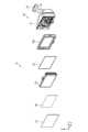
図1は、第1実施形態に係る電子ミラー1の一例を示す正面図である。図2は、第1実施形態に係る電子ミラー1の一例を示す分解斜視図である。図3は、図1に示す電子ミラー1のA-A矢視の断面図である。なお、電子ミラー1の幅方向をX軸方向とし、電子ミラー1の高さ方向をY軸方向とし、電子ミラー1の奥行方向をZ軸方向とする。また、電子ミラー1において画像が表示される側を正面側とし、正面側とは反対の側を背面側とする。(First embodiment)
FIG. 1 is a front view showing an example of an
電子ミラー1は、例えば車両の室内に配置される電子インナーミラーである。電子ミラー1は、表示装置およびミラーとして機能する。具体的には、電子ミラー1は、表示装置として機能する場合に、車両の後方を撮影するカメラが撮影した画像を表示する。また、電子ミラー1は、ミラーとして機能する場合に、光を反射することにより車両の後方を映す。また、電子ミラー1は、表示装置、及び車載表示装置の一例である。 The
電子ミラー1は、表示装置として機能するディスプレイモードと、ミラーとして機能するミラーモードとを有する。ディスプレイモードは、電子ミラー1が、車両の後方を撮影するカメラが撮影した画像を表示するモードである。ミラーモードは、電子ミラー1が、電子ミラー1に入射した光を反射することにより車両の後方を映すモードである。例えば、電子ミラー1は、レバーなどによる操作を受け付けることで、ディスプレイモードと、ミラーモードとを切り替える。 The
図2に示すように、電子ミラー1は、カバーレンズ10、両面テープ20、フレーム30、ディスプレイ40、及びハウジング50を有する。カバーレンズ10は、可視光を透過するカバーである。更に詳しくは、カバーレンズ10は、電子ミラー1の正面を覆うように、透明な部材により形成される。例えば、カバーレンズ10は、樹脂により形成される。カバーレンズ10は、ガラスにより形成されてもよい。カバーレンズ10は、樹脂により形成されることで、ガラスにより形成される場合よりも軽量化される。 As shown in FIG. 2, the
また、カバーレンズ10は、フレーム30に対応する位置に、可視光を反射することにより像を映すミラー部11を有する。フレーム30に対応する位置とは、電子ミラー1を正面から見たときに、少なくとも一部がフレーム30と重なる位置を指す。ミラー部11は、電子ミラー1を正面から見たときに、フレーム30の全体と重なる、あるいはフレーム30よりもはみ出すように形成されてもよい。ミラー部11は、鏡面状に形成された銀色の被膜により、入射した光を反射する部分である。これにより、ミラー部11は、鏡のように像を映す。ここで、カバーレンズ10は透明であるため、カバーレンズ10よりも背面側にある部材がカバーレンズ10を介して視認される場合がある。背面側にある部材とは、例えば後述する両面テープ20及びフレーム30である。カバーレンズ10にミラー部11を設けることにより、ミラー部11は、両面テープ20やフレーム30を隠し、且つ車両の後方を映すことができる。これにより、電子ミラー1は、ミラーモードの場合に、全面を鏡にすることができる。 Moreover, the
両面テープ20は、両面に接着剤が塗布されたテープである。両面テープ20は、カバーレンズ10とフレーム30とを接着する。 The double-
フレーム30は、ハウジング50と接合し、ディスプレイ40の縁を覆う外枠である。また、フレーム30は、カバーレンズ10を支持する。例えば、両面テープ20により貼り付けられることで、フレーム30は、カバーレンズ10を支持する。 The
また、フレーム30は、ディスプレイ40の縁を覆う外枠部31と、ハウジング50と接合する接合部32とを備える。外枠部31は、ディスプレイ40が有するLCD(Liquid Crystal Display)セル44と略平行であって、ディスプレイ40の縁を覆う平面状の板を有する。接合部32は、ハウジング50が有する凸部54が挿入される凹部33を有する。接合部32は、凹部33に凸部54が挿入されることによりハウジング50と接合する。 The
ディスプレイ40は、画像を表示する。更に詳しくは、ディスプレイ40は、車両の後方を撮影するカメラが撮影した画像を表示する。なお、ディスプレイ40は、有線又は無線により接続されていれば、車両の後方を撮影するカメラに限らず、他のカメラが撮影した画像を表示してもよい。 The
また、ディスプレイ40と、フレーム30との間には、パッド41が配置される。パッド41は、ディスプレイ40とフレーム30との間の隙間を埋める。これにより、パッド41は、埃や塵などのゴミが電子ミラー1の内部に入ることを抑制する。 A
ディスプレイ40は、ディスプレイ筐体42と、偏光反射層43と、LCDセル44と、ディスプレイ制御部46とを備える。ディスプレイ筐体42は、ディスプレイ40を覆う筐体である。 The
偏光反射層43は、カバーレンズ10とディスプレイ40との間であって、ディスプレイ40の表面441に設けられる。また、偏光反射層43は、カバーレンズ10を介して入射した光の一部を反射し、且つ、ディスプレイ40が表示した画像の光を透過する。偏光反射層43は、偏光反射部の一例である。すなわち、偏光反射層43は、ミラーモードの場合に鏡として光を反射し、ディスプレイモードの場合にディスプレイ40が表示した画像の光を正面側に向かって透過する。 The polarized
更に詳しくは、偏光反射層43は、特定方向に偏光又は偏波された光を透過させ、特定方向とは異なる方向の光を反射する。また、偏光反射層43は、LCDセル44が出射した光を透過させる。また、偏光反射層43は、OCA(Optical Clear Adhesive)などの透明な接着剤45により、ディスプレイ40の表面441に貼り付けられる。具体的には、偏光反射層43は、LCDセル44の表面441に貼り付けられる。 More specifically, the
LCDセル44は、ガラス基板の間に液晶が注入された部材である。ディスプレイ40は、LCDセル44を介して光を出射することにより画像を表示する。 The
ディスプレイ制御部46は、ディスプレイ40を制御する。例えば、ディスプレイ制御部46は、ディスプレイ40を制御する回路基板や、LCDセル44に光を放射するバックライトや、車両に搭載されたカメラから画像を受信する受信部などを有する。ディスプレイ制御部46は、ディスプレイモードの場合に、車両に搭載されたカメラが撮影した画像をLCDセル44に表示させる。 A
ハウジング50は、ディスプレイ40を収容し、車両に取り付けられる。ハウジング50は、収容部51と、アーム部52と、取付部53とを備える。収容部51は、ディスプレイ40を収容する筐体である。また、収容部51は、正面側に凸部54を有する。凸部54は、フレーム30の接合部32に設けられた凹部33に挿入される。これにより、ハウジング50の収容部51は、フレーム30と接合する。そして、ハウジング50と、フレーム30とは、ディスプレイ40の周囲を覆う筐体である。すなわち、ハウジング50と、フレーム30とは、筐体の一例である。 A
アーム部52は、ハウジング50と取付部53とを連結する腕状の部材である。また、アーム部52は、ディスプレイ40の角度を変更する関節を有していてもよい。これにより、ユーザは、電子ミラー1を見やすい角度に調整することができる。例えば、電子ミラー1は、ディスプレイモードとミラーモードとで、角度を変更可能であってもよい。 The
取付部53は、車両の室内に取り付けられる部材である。例えば、取付部53は、車両の天井やフロントガラスに取り付けられる。これにより、電子ミラー1は、車両に取り付けられる。 The
以上のように、第1実施形態に係る電子ミラー1は、可視光を透過するカバーレンズ10と、画像を表示するディスプレイ40と、ディスプレイ40のLCDセル44に配置された偏光反射層43と、を備える。そして、偏光反射層43は、カバーレンズ10を介して入射した光を反射し、且つ、LCDセル44に表示された画像の光を偏光する。すなわち、偏光反射層43は、LCDセル44に表示された画像の光を偏光する偏光板としても機能する。よって、電子ミラー1は、複数の部材における役割の重複を解消することができる。 As described above, the
また、電子ミラー1は、LCDセル44に偏光反射層43が配置される。これにより、カバーレンズ10を、ガラスよりも軽量な樹脂により形成することができる。ここで、樹脂は、ガラスよりも柔らかく、変形しやすい。そのため、樹脂により形成されたカバーレンズに、偏光反射層を配置すると、偏光反射層の平面度を維持することが難しく、反射像が歪むという課題がある。第1実施形態に係る電子ミラー1では、硬度が高いLCDセル44に偏光反射層43が配置される。これにより、電子ミラー1における偏光反射層43の平面度を維持することができ、反射像が歪んでしまうことを抑制することができる。 Further, the
また、図3に示すように、カバーレンズ10は、フレーム30の正面側に貼り付けられる。フレーム30は、カバーレンズ10の端を覆う縁を有していてもよい。国や地域によっては法規によりカバーレンズ10の端を覆う縁を有することが求められているため、これにより、そのような国や地域で電子ミラー1を利用することができる。 Also, as shown in FIG. 3, the
(第2実施形態)
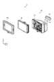
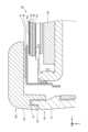
図4は、第2実施形態に係る電子ミラー1aの一例を示す分解斜視図である。図5は、第2実施形態に係る電子ミラー1aの断面図である。なお、第2実施形態に係る電子ミラー1aの正面は、図1に示す第1実施形態に係る電子ミラー1と略同じであるため正面図を省略している。(Second embodiment)
FIG. 4 is an exploded perspective view showing an example of the
図4に示すように、電子ミラー1aは、カバーレンズ10aと、OCA60と、VRM(Variable Reflectance Mirror)70と、両面テープ20と、フレーム30aと、ディスプレイ40と、ハウジング50とを有する。 As shown in FIG. 4, the
電子ミラー1aは、ミラーモードの場合に鏡として機能するVRM70を有している。カバーレンズ10aにおける、カバーレンズ10aの縁から、VRM70が設けられている位置までの領域に、鏡のように像を映すミラー部11が設けられている。図5に示す例では、電子ミラー1aを正面から見たときに、VRM70が設けられている位置よりも外側にミラー部11が設けられている。 The
OCA60は、カバーレンズ10aと、VRM70とを接着する透明な接着剤である。 The
VRM70は、印加された電圧に応じて入射光に対する反射率及び透過率を変更する。例えば、VRM70は、ディスプレイモードの場合には、入射光に対する透過率を上げる。すなわち、VRM70は、VRM70よりも背面側に配置されたディスプレイ40が表示した画像の光を透過させる。一方、VRM70は、ミラーモードの場合には、入射光に対する反射率を上げる。すなわち、VRM70は、カバーレンズ10aを介して入射した光を反射させる。
VRM70は、偏光部71と、TN(Twisted Nematic)液晶部72と、接着剤73とを有する。また、LCDセル44の表面441に設けられた偏光反射層43は、VRM70の一部として機能する。 The
偏光部71は、カバーレンズ10aと偏光反射層43との間であってカバーレンズ10a側に設けられ、カバーレンズ10aを介して入射した光を偏光する。更に詳しくは、偏光部71は、カバーレンズ10aを介して入射した光のうち、特定方向に偏光又は偏波した光を透過させる偏光板である。また、偏光部71は、特定方向とは異なる方向の光を吸収する。 The
TN液晶部72は、TN方式の液晶パネルである。TN液晶部72は、偏光部71と、偏光反射層43との間に位置し、偏光部71を介して入射した光の偏光方向を変更する。TN液晶部72は、液晶部の一例である。更に詳しくは、TN液晶部72は、電圧が印加された場合に、液晶材料の分子の並び方を垂直方向に変える。それにより、TN液晶部72は、透過する光を直進させる。一方、TN液晶部72は、電圧が印加されない場合に、液晶材料の分子の並び方を変更しない。それにより、TN液晶部72は、TN液晶部72を透過する光の偏光方向を変更する。例えば、TN液晶部72は、光の偏光方向を90度ねじる。液晶部の例はこれに限られない。例えば、電圧が印加された場合に、透過する光の偏光方向を変更し、電圧が印加されない場合に、透過する光を直進させるような液晶部であってもよい。 The TN
また、TN液晶部72は、接着剤73により、偏光部71に貼り付けられる。接着剤73は、接着剤45と同様に、透明なOCAなどを用いることができる。 Also, the TN
偏光反射層43は、偏光部71と同一方向の光を透過させる。言い換えると、偏光反射層43は、TN液晶部72を直進した光を透過させる。また、偏光反射層43は、TN液晶部72により偏光方向が変えられた光を反射する。これにより、偏光反射層43は、TN液晶部72を介して入射した光の一部を反射し、且つ、ディスプレイ40が表示した画像の光を透過する。 The polarizing reflecting
このような構成において、ディスプレイモードの場合、偏光反射層43は、LCDセル44が表示した画像の光のうち、特定方向に偏光又は偏波した光を透過させる。また、ディスプレイモードの場合、VRM70には、電圧が印加される。よって、TN液晶部72は、偏光反射層43から入射された光の偏光方向を変更せずに直進させる。また、TN液晶部72を透過した光は、偏光部71を透過する。そして、偏光部71を透過した光は、OCA60及びカバーレンズ10aを介して放出される。これにより、電子ミラー1aは、画像を表示する。 In such a configuration, in the display mode, the polarizing
一方、ミラーモードの場合、TN液晶部72には、電圧が印加されない。よって、TN液晶部72は、液晶材料の分子により、偏光部71から入射された光の偏光方向を変更する。そして、偏光反射層43は、TN液晶部72により偏光方向が変えられた光を反射する。 On the other hand, in the mirror mode, no voltage is applied to the TN
TN液晶部72は、偏光反射層43が反射した光の偏光方向を変更する。その結果、TN液晶部72を透過した光は、偏光部71を透過した時の角度に戻る。そして、TN液晶部72を透過した光は、偏光部71を透過する。偏光部71を透過した光は、OCA60及びカバーレンズ10aを介して放出される。このようにして、電子ミラー1aは、ミラーモードにおいて、光を反射させる。 The TN
図5に示すように、TN液晶部72及び偏光部71は、カバーレンズ10aと、フレーム30aとの間に配置される。フレーム30aは、TN液晶部72及び偏光部71が配置される空間を設けるために、階段形状を有する。フレーム30aは、両面テープ20によりカバーレンズ10aと接着する面から一段低い位置に、TN液晶部72及び偏光部71が配置される配置部34を有する。そして、ディスプレイ40は、配置部34よりも背面側に配置される。 As shown in FIG. 5, the TN
以上のように、第2実施形態に係る電子ミラー1aは、カバーレンズ10aと偏光反射層43との間に設けられ、カバーレンズ10aを介して入射した光を偏光する偏光部71と、偏光部71を介して入射した光の偏光方向を変更するTN液晶部72と、を備える。そして、ディスプレイ40のLCDセル44に配置された偏光反射層43は、VRM70の偏光反射板としても機能する。よって、電子ミラー1aは、複数の部材におけるいて役割の重複を解消することができる。 As described above, the
また、図5に示すように、カバーレンズ10aは、フレーム30aの正面側に貼り付けられる。フレーム30aは、カバーレンズ10aの端を覆う縁を有していてもよい。国や地域によっては法規によりカバーレンズ10aの端を覆う縁を有することが求められているため、これにより、そのような国や地域で電子ミラー1aを利用することができる。 Also, as shown in FIG. 5, the
(第3実施形態)
図6は、第3実施形態に係る電子ミラー1bの一例を示す分解斜視図である。図7は、第3実施形態に係る電子ミラー1bの断面図である。なお、第3実施形態に係る電子ミラー1bの正面は、図1に示す第1実施形態に係る電子ミラー1と略同じであるため正面図を省略している。(Third Embodiment)
FIG. 6 is an exploded perspective view showing an example of the
図6に示すように、電子ミラー1bは、カバーレンズ10と、OCA60と、ディスプレイ40と、両面テープ20と、フレーム30bと、ハウジング50とを有する。 As shown in FIG. 6, the
OCA60は、透明な接着剤である。カバーレンズ10と、ディスプレイ40とは、OCA60により接着される。更に詳しくは、OCA60は、カバーレンズ10と、LCDセル44の表面441に形成された偏光反射層43とを接着する。言い換えると、カバーレンズ10と、ディスプレイ40とは、OCA60により接着される。このため、図7に示すように、フレーム30bは、ディスプレイ40の縁を覆う外枠が無い。 OCA60 is a transparent adhesive. The
ディスプレイ40は、OCA60によりカバーレンズ10に接着される。また、ディスプレイ40は、車両に搭載されたカメラが撮像した画像を表示するLCDセル44を有する。そして、LCDセル44は、正面側の表面441に偏光反射層43を有する。
以上のように、第3実施形態に係る電子ミラー1bは、カバーレンズ10と、偏光反射層43が配置されたLCDセル44とがOCA60により接着されている。この場合においても、偏光反射層43は、カバーレンズ10を介して入射した光の反射し、LCDセル44に表示された画像の光を偏光する。すなわち、偏光反射層43は、LCDセル44に表示された画像の光を偏光する偏光板としても機能する。よって、電子ミラー1bは、複数の部材において役割の重複を解消することができる。 As described above, in the
また、図7に示すように、カバーレンズ10は、フレーム30bの正面側に貼り付けられる。フレーム30bは、カバーレンズ10の端を覆う縁を有していてもよい。国や地域によっては法規によりカバーレンズ10の端を覆う縁を有することが求められているため、これにより、そのような国や地域で電子ミラー1bを利用することができる。 Also, as shown in FIG. 7, the
(第4実施形態)
図8は、第4実施形態に係る電子ミラー1cの一例を示す正面図である。図9は、第4実施形態に係る電子ミラー1cの一例を示す分解斜視図である。図10は、図8に示す電子ミラー1cのA-A矢視の断面図である。(Fourth embodiment)
FIG. 8 is a front view showing an example of an
第4実施形態に係る電子ミラー1cは、電子ミラー1のカバーレンズ10及び両面テープ20を有していない。すなわち、図9に示すように、電子ミラー1cは、フレーム30cと、ディスプレイ40と、ハウジング50とを有する。 The
図10に示すように、電子ミラー1cは、カバーレンズ10が無いため、ディスプレイ40が露出している。更に詳しくは、電子ミラー1cにおいて、LCDセル44の表面441に設けられた偏光反射層43が露出している。すなわち、偏光反射層43は、ディスプレイ40の表面441に設けられ、ディスプレイ40の反対側から入射した光の一部を反射し且つディスプレイ40が表示した画像の光を透過する。 As shown in FIG. 10, since the
また、カバーレンズ10が無いため、フレーム30cは、ディスプレイ40の外枠となる。よって、フレーム30cは、曲線を有する外観になっている。 Also, since there is no
以上のように、第4実施形態に係る電子ミラー1cは、カバーレンズ10を有していない。この場合においても、偏光反射層43は、入射した光の反射し、LCDセル44に表示された画像の光を偏光する。すなわち、偏光反射層43は、LCDセル44に表示された画像の光を偏光板としても機能する。よって、電子ミラー1cは、複数の部材において役割の重複を解消することができる。 As described above, the
本開示のいくつかの実施形態を説明したが、これらの実施形態は、例として提示したものであり、発明の範囲を限定することは意図していない。これらの実施形態は、その他の様々な形態で実施されることが可能であり、発明の要旨を逸脱しない範囲で、種々の省略、置き換え、変更を行うことができる。これらの実施形態やその変形は、発明の範囲や要旨に含まれると同様に、特許請求の範囲に記載された発明とその均等の範囲に含まれるものである。 While several embodiments of the disclosure have been described, these embodiments have been presented by way of example and are not intended to limit the scope of the invention. These embodiments can be implemented in various other forms, and various omissions, replacements, and modifications can be made without departing from the scope of the invention. These embodiments and their modifications are included in the scope and spirit of the invention, as well as the scope of the invention described in the claims and equivalents thereof.
1、1a、1b、1c 電子ミラー
10、10a カバーレンズ
11 ミラー部
20 両面テープ
30、30a、30b、30c フレーム
31 外枠部
32 接合部
33 凹部
34 配置部
40 ディスプレイ
41 パッド
42 ディスプレイ筐体
43 偏光反射層
44 LCD(Liquid Crystal Display)セル
441 表面
45、73 接着剤
46 ディスプレイ制御部
50 ハウジング
51 収容部
52 アーム部
53 取付部
54 凸部
60 OCA(Optical Clear Adhesive)
70 VRM(Variable Reflectance Mirror)
71 偏光部
72 TN(Twisted Nematic)液晶部
70VRM (Variable Reflectance Mirror)
71
Claims (8)
Translated fromJapanese画像を表示するディスプレイと、
前記カバーと前記ディスプレイとの間であって前記ディスプレイの表面に設けられ、前記カバーを介して入射した光の一部を反射し、且つ、前記ディスプレイが表示した前記画像の光を透過する偏光反射部と、
を備える表示装置。a cover transparent to visible light;
a display for displaying images;
A polarized light reflector provided between the cover and the display and on the surface of the display to reflect part of the light incident through the cover and to transmit the light of the image displayed by the display. Department and
A display device.
前記偏光部と、前記偏光反射部との間に位置し、前記偏光部を介して入射した光の偏光方向を変更する液晶部と、
を更に備え、
前記偏光反射部は、前記液晶部を介して入射した光の一部を反射し、且つ、前記ディスプレイが表示した前記画像の光を透過する、
請求項1に記載の表示装置。a polarizing section provided between the cover and the polarizing reflecting section and on the cover side for polarizing light incident through the cover;
a liquid crystal unit positioned between the polarizing unit and the polarizing reflecting unit and configured to change the polarization direction of light incident through the polarizing unit;
further comprising
The polarized light reflecting section reflects part of the light incident through the liquid crystal section and transmits the light of the image displayed by the display.
The display device according to claim 1.
請求項1に記載の表示装置。the cover and the polarizing reflector are adhered together;
The display device according to claim 1.
前記カバーは、前記フレームに対応する位置に、可視光を反射することにより像を映すミラー部を有する、
請求項1から請求項3の何れか一項に記載の表示装置。further comprising a frame that supports the cover;
The cover has, at a position corresponding to the frame, a mirror portion that projects an image by reflecting visible light.
The display device according to any one of claims 1 to 3.
請求項1から請求項4の何れか一項に記載の表示装置。The display displays the image captured by a camera that captures the rear of the vehicle.
The display device according to any one of claims 1 to 4.
請求項1から請求項5の何れか一項に記載の表示装置。wherein the cover is made of resin,
The display device according to any one of claims 1 to 5.
前記ディスプレイの表面に設けられ、当該ディスプレイの反対側から入射した光の一部を反射し、且つ、前記ディスプレイが表示した前記画像の光を透過する偏光反射部と、
前記ディスプレイの周囲を覆う筐体と、
前記車両の室内に取り付けられる取付部と、
を備える車載表示装置。a display that displays an image captured by a camera that captures the rear of the vehicle;
a polarizing reflector that is provided on the surface of the display, reflects part of the light incident from the opposite side of the display, and transmits the light of the image displayed by the display;
a housing that surrounds the display;
a mounting portion that is mounted in the interior of the vehicle;
In-vehicle display device.
請求項7に記載の車載表示装置。Further comprising an arm for changing the angle of the display,
The in-vehicle display device according to claim 7.
Priority Applications (4)
| Application Number | Priority Date | Filing Date | Title |
|---|---|---|---|
| JP2022011266AJP2023109630A (en) | 2022-01-27 | 2022-01-27 | Display device and in-vehicle display device |
| US18/074,030US20230236456A1 (en) | 2022-01-27 | 2022-12-02 | Display device and in-vehicle display device |
| DE202022106842.9UDE202022106842U1 (en) | 2022-01-27 | 2022-12-07 | Display device and in-vehicle display device |
| CN202223275944.9UCN219122922U (en) | 2022-01-27 | 2022-12-07 | Display device and vehicle-mounted display device |
Applications Claiming Priority (1)
| Application Number | Priority Date | Filing Date | Title |
|---|---|---|---|
| JP2022011266AJP2023109630A (en) | 2022-01-27 | 2022-01-27 | Display device and in-vehicle display device |
Publications (1)
| Publication Number | Publication Date |
|---|---|
| JP2023109630Atrue JP2023109630A (en) | 2023-08-08 |
Family
ID=84890238
Family Applications (1)
| Application Number | Title | Priority Date | Filing Date |
|---|---|---|---|
| JP2022011266APendingJP2023109630A (en) | 2022-01-27 | 2022-01-27 | Display device and in-vehicle display device |
Country Status (4)
| Country | Link |
|---|---|
| US (1) | US20230236456A1 (en) |
| JP (1) | JP2023109630A (en) |
| CN (1) | CN219122922U (en) |
| DE (1) | DE202022106842U1 (en) |
Families Citing this family (2)
| Publication number | Priority date | Publication date | Assignee | Title |
|---|---|---|---|---|
| USD1086283S1 (en)* | 2024-02-05 | 2025-07-29 | Toyota Jidosha Kabushiki Kaisha | Vehicle mounted information display device |
| USD1078671S1 (en)* | 2024-08-20 | 2025-06-10 | Shenzhen Yuzhongqi Technology Co., Ltd. | Vehicle display device |
Citations (5)
| Publication number | Priority date | Publication date | Assignee | Title |
|---|---|---|---|---|
| US20090015736A1 (en)* | 2005-11-01 | 2009-01-15 | Donnelly Corporation | Interior rearview mirror assembly with display |
| JP2010221899A (en)* | 2009-03-24 | 2010-10-07 | Murakami Corp | Vehicular mirror with monitor |
| WO2014112525A1 (en)* | 2013-01-16 | 2014-07-24 | シャープ株式会社 | Mirror display, half mirror plate, and electronic device |
| CN109515325A (en)* | 2017-09-20 | 2019-03-26 | 威斯通全球技术公司 | Electronics reflective mirror with enhanced switchable lens |
| JP2021154930A (en)* | 2020-03-27 | 2021-10-07 | パナソニックIpマネジメント株式会社 | Display and control circuit |
Family Cites Families (4)
| Publication number | Priority date | Publication date | Assignee | Title |
|---|---|---|---|---|
| US10227046B2 (en)* | 2014-10-27 | 2019-03-12 | Magna Mirrors Of America, Inc. | Sun visor and vanity mirror assembly for vehicle |
| JP2017111267A (en) | 2015-12-16 | 2017-06-22 | 富士フイルム株式会社 | Mirror with vehicle-purposed image display function, and manufacturing method of the same |
| KR20180086262A (en)* | 2015-12-17 | 2018-07-30 | 쓰리엠 이노베이티브 프로퍼티즈 컴파니 | A mirror comprising a reflective backlit display |
| US11766968B2 (en)* | 2021-05-18 | 2023-09-26 | Magna Mirrors Of America, Inc. | Vehicular interior rearview mirror assembly with video mirror display and VRLC stack |
- 2022
- 2022-01-27JPJP2022011266Apatent/JP2023109630A/enactivePending
- 2022-12-02USUS18/074,030patent/US20230236456A1/ennot_activeAbandoned
- 2022-12-07CNCN202223275944.9Upatent/CN219122922U/enactiveActive
- 2022-12-07DEDE202022106842.9Upatent/DE202022106842U1/enactiveActive
Patent Citations (5)
| Publication number | Priority date | Publication date | Assignee | Title |
|---|---|---|---|---|
| US20090015736A1 (en)* | 2005-11-01 | 2009-01-15 | Donnelly Corporation | Interior rearview mirror assembly with display |
| JP2010221899A (en)* | 2009-03-24 | 2010-10-07 | Murakami Corp | Vehicular mirror with monitor |
| WO2014112525A1 (en)* | 2013-01-16 | 2014-07-24 | シャープ株式会社 | Mirror display, half mirror plate, and electronic device |
| CN109515325A (en)* | 2017-09-20 | 2019-03-26 | 威斯通全球技术公司 | Electronics reflective mirror with enhanced switchable lens |
| JP2021154930A (en)* | 2020-03-27 | 2021-10-07 | パナソニックIpマネジメント株式会社 | Display and control circuit |
Also Published As
| Publication number | Publication date |
|---|---|
| DE202022106842U1 (en) | 2022-12-23 |
| CN219122922U (en) | 2023-06-02 |
| US20230236456A1 (en) | 2023-07-27 |
Similar Documents
| Publication | Publication Date | Title |
|---|---|---|
| TWI652526B (en) | Display assembly mechanism and related display device | |
| JP4330764B2 (en) | Liquid crystal display | |
| CN105659145B (en) | Display device | |
| JP2008216934A (en) | Display device | |
| US20230236456A1 (en) | Display device and in-vehicle display device | |
| KR100945359B1 (en) | LCD Display | |
| JP7207162B2 (en) | head-up display device | |
| CN106932939B (en) | Liquid crystal display device | |
| US10259393B2 (en) | Mirror display device | |
| JP2014238477A (en) | Head-up display device | |
| WO2019097935A1 (en) | Vehicle inner mirror | |
| EP3460536A1 (en) | Electronic mirror with an enhanced switchable lens system | |
| JPWO2019208425A1 (en) | Liquid crystal display device | |
| JP7304573B2 (en) | head-up display device | |
| JP2010276776A (en) | Head-up display device | |
| JP2016045362A (en) | Display device | |
| JP2010243758A (en) | Head-up display | |
| JP2009109798A (en) | Headup display device | |
| JP2001117069A (en) | Display device and display panel used for display device | |
| JP7552305B2 (en) | Head-up display | |
| US20040212581A1 (en) | Backlight device | |
| JP2018083521A (en) | Head-up display device | |
| KR20170015727A (en) | Display Device | |
| TWI859985B (en) | Display apparatus and display holding device thereof | |
| KR102729993B1 (en) | Display device for a vehicle |
Legal Events
| Date | Code | Title | Description |
|---|---|---|---|
| A711 | Notification of change in applicant | Free format text:JAPANESE INTERMEDIATE CODE: A711 Effective date:20240226 | |
| A621 | Written request for application examination | Free format text:JAPANESE INTERMEDIATE CODE: A621 Effective date:20240801 | |
| A977 | Report on retrieval | Free format text:JAPANESE INTERMEDIATE CODE: A971007 Effective date:20250213 | |
| A131 | Notification of reasons for refusal | Free format text:JAPANESE INTERMEDIATE CODE: A131 Effective date:20250311 | |
| A521 | Request for written amendment filed | Free format text:JAPANESE INTERMEDIATE CODE: A523 Effective date:20250425 | |
| A131 | Notification of reasons for refusal | Free format text:JAPANESE INTERMEDIATE CODE: A131 Effective date:20250520 |