Movatterモバイル変換


[0]ホーム

URL:


JP2023103865A - medical device - Google Patents

medical device
Download PDF

Info

Publication number
JP2023103865A
JP2023103865AJP2022004640AJP2022004640AJP2023103865AJP 2023103865 AJP2023103865 AJP 2023103865AJP 2022004640 AJP2022004640 AJP 2022004640AJP 2022004640 AJP2022004640 AJP 2022004640AJP 2023103865 AJP2023103865 AJP 2023103865A
Authority
JP
Japan
Prior art keywords
unit
wire
pressing
medical device
catheter
Prior art date
Legal status (The legal status is an assumption and is not a legal conclusion. Google has not performed a legal analysis and makes no representation as to the accuracy of the status listed.)
Pending
Application number
JP2022004640A
Other languages
Japanese (ja)
Inventor
亮 岩沢
Ryo Iwasawa
悠介 新川
Yusuke Shinkai
富生 野口
Tomio Noguchi
Current Assignee (The listed assignees may be inaccurate. Google has not performed a legal analysis and makes no representation or warranty as to the accuracy of the list.)
Canon Inc
Original Assignee
Canon Inc
Priority date (The priority date is an assumption and is not a legal conclusion. Google has not performed a legal analysis and makes no representation as to the accuracy of the date listed.)
Filing date
Publication date
Application filed by Canon IncfiledCriticalCanon Inc
Priority to JP2022004640ApriorityCriticalpatent/JP2023103865A/en
Priority to PCT/JP2022/044177prioritypatent/WO2023135965A1/en
Publication of JP2023103865ApublicationCriticalpatent/JP2023103865A/en
Pendinglegal-statusCriticalCurrent

Links

Images

Classifications

Landscapes

Abstract

Translated fromJapanese

【課題】湾曲可能ユニットのベースユニットに対する着脱性を向上する。【解決手段】医療装置は、駆動源に接続された連結部を備えるベースユニットと、前記ベースユニットに取り外し可能に装着される湾曲可能ユニットであって、湾曲可能な湾曲部と、前記連結部に連結可能な被連結部を有する線状部材と、を有する湾曲可能ユニットと、を備える。前記連結部は、押圧位置と、離間位置と、に移動可能な押圧部と、前記押圧部によって交差方向に押圧された前記被連結部に当接する当接部と、を有する。前記被連結部及び前記当接部のいずれか一方には、凹部が設けられ、前記被連結部及び前記当接部のいずれか他方には、前記凹部に係合可能な凸部が設けられる。前記凹部及び前記凸部は、前記押圧部が前記押圧位置に位置する際に、移動方向に見て互いに重なるように係合している。【選択図】図1An object of the present invention is to improve attachment/detachment of a bendable unit to/from a base unit. A medical device includes a base unit having a connecting portion connected to a drive source, and a bendable unit detachably attached to the base unit, the bendable bending portion and the connecting portion. and a bendable unit having a linear member having a connectable connected portion. The connecting portion has a pressing portion movable between a pressing position and a separated position, and a contact portion that contacts the connected portion pressed in the cross direction by the pressing portion. One of the connected portion and the abutment portion is provided with a recess, and the other of the connection portion and the abutment portion is provided with a protrusion engageable with the recess. The concave portion and the convex portion engage with each other so as to overlap each other when the pressing portion is positioned at the pressing position when viewed in the moving direction. [Selection drawing] Fig. 1

Description

Translated fromJapanese

本発明は、湾曲可能な湾曲部を有する医療装置に関する。 The present invention relates to a medical device having a bendable bending portion.

特許文献1によると、変形部を有する湾曲可能ユニットと、変形部を変形させるベースユニットと、を備え、湾曲可能ユニットがベースユニットに対して着脱可能となっている医療器具が開示されている。湾曲可能ユニットをベースユニットに装着した際には、湾曲可能ユニットが有するワイヤとベースユニットが有する連結部を確実に連結させる必要がある。このため、ワイヤの移動方向(長手方向)と直交する方向、すなわち断面方向においてワイヤと連結部が重なるように、ワイヤと連結部を係合させる構成になっている。Patent Literature 1 discloses a medical device that includes a bendable unit having a deformable portion and a base unit that deforms the deformable portion, and the bendable unit is detachable from the base unit. When the bendable unit is attached to the base unit, it is necessary to reliably connect the wire of the bendable unit and the connecting portion of the base unit. For this reason, the wire and the connecting portion are engaged with each other so that the wire and the connecting portion overlap in a direction perpendicular to the movement direction (longitudinal direction) of the wire, that is, in the cross-sectional direction.

米国特許出願公開第2021/0121051号明細書U.S. Patent Application Publication No. 2021/0121051

上記特許文献1に記載の医療器具は、湾曲可能ユニットをベースユニットに対し回転させることで湾曲可能ユニットの着脱が可能となっている。すなわち、操作者が湾曲可能ユニットを回転させることで、ワイヤと連結部とが連結される。しかしながら、湾曲可能ユニットをベースユニットに対して着脱する際の、操作者の操作負荷が高く、湾曲可能ユニットの着脱性に課題があった。 In the medical device described inPatent Document 1, the bendable unit can be attached and detached by rotating the bendable unit with respect to the base unit. That is, the wire and the connecting portion are connected by the operator rotating the bendable unit. However, when the bendable unit is attached to and detached from the base unit, the operator's operation load is high, and there is a problem in the attachment and detachment of the bendable unit.

本発明の目的の一つは、湾曲可能ユニットのベースユニットに対する着脱性を向上することである。 One of the objects of the present invention is to improve the detachability of the bendable unit with respect to the base unit.

本発明の一態様は、医療装置において、駆動源と、前記駆動源に接続された連結部を備えるベースユニットと、前記ベースユニットに取り外し可能に装着される湾曲可能ユニットであって、湾曲可能な湾曲部と、前記連結部に連結可能な被連結部を有し、前記連結部を介して前記駆動源によって移動方向に移動されることで前記湾曲部を湾曲させる線状部材と、を有する湾曲可能ユニットと、を備え、前記連結部は、前記湾曲可能ユニットが前記ベースユニットに装着された状態で前記被連結部を前記移動方向に交差する交差方向に押圧可能な押圧位置と、前記押圧位置よりも前記被連結部から離間した離間位置と、に移動可能な押圧部と、前記押圧部によって前記交差方向に押圧された前記被連結部に当接する当接部と、を有し、前記被連結部及び前記当接部のいずれか一方には、凹部が設けられ、前記被連結部及び前記当接部のいずれか他方には、前記凹部に係合可能な凸部が設けられ、前記凹部及び前記凸部は、前記湾曲可能ユニットが前記ベースユニットに装着された状態で前記押圧部が前記押圧位置に位置する際に、前記移動方向に見て互いに重なるように係合している、ことを特徴とする。 One aspect of the present invention is a medical device comprising a drive source, a base unit including a connecting portion connected to the drive source, and a bendable unit detachably attached to the base unit, the bendable and a linear member that has a bending portion and a connected portion that can be connected to the connecting portion, and that is moved in a movement direction by the driving source via the connecting portion to bend the bending portion. a bendable unit, wherein the connecting portion has a pressing position capable of pressing the connected portion in a direction intersecting the movement direction in a state in which the bendable unit is attached to the base unit; and the pressing position. and a pressing portion movable to a spaced position spaced apart from the connected portion by a distance of more than the connecting portion; One of the connecting portion and the contact portion is provided with a recess, and the other of the connected portion and the contact portion is provided with a protrusion engageable with the recess. and the convex portions are engaged so as to overlap each other when viewed in the moving direction when the pressing portion is positioned at the pressing position with the bendable unit attached to the base unit. characterized by

本発明によると、湾曲可能ユニットのベースユニットに対する着脱性を向上することができる。 According to the present invention, attachment/detachment of the bendable unit to/from the base unit can be improved.

医療システムの全体図。An overview of the medical system.医療装置および支持台を示す斜視図。1 is a perspective view showing a medical device and a support base; FIG.(a)はカテーテルを示す全体斜視図、(b)はカテーテルを示す拡大斜視図。(a) is an overall perspective view showing the catheter, and (b) is an enlarged perspective view showing the catheter.(a)はワイヤカバーがカバー位置にある状態のカテーテルユニットを示す斜視図、(b)はワイヤカバーが露出位置にある状態のカテーテルユニットを示す斜視図。(a) is a perspective view showing the catheter unit with the wire cover at the cover position, and (b) is a perspective view showing the catheter unit with the wire cover at the exposed position.(a)はベースユニットの内部構造を示す斜視図、(b)はベースユニットの内部構造を示す側面図、(c)はベースユニットを着脱方向DEに沿って見た図。(a) is a perspective view showing the internal structure of the base unit, (b) is a side view showing the internal structure of the base unit, and (c) is a view of the base unit as seen along the attachment/detachment direction DE.(a)は駆動源、連結部及び駆動ワイヤを示す斜視図、(b)は連結部及び駆動ワイヤを示す拡大図、(c)はワイヤ駆動部、連結装置及び湾曲駆動部を示す斜視図。(a) is a perspective view showing a drive source, a connecting portion and a driving wire, (b) is an enlarged view showing the connecting portion and a driving wire, and (c) is a perspective view showing a wire driving portion, a connecting device and a bending driving portion.(a)はカテーテルユニットがベースユニットに装着される前の様子を示す断面図、(b)はカテーテルユニットがベースユニットに装着された後の様子を示す断面図。(a) is a sectional view showing a state before the catheter unit is attached to the base unit, and (b) is a sectional view showing a state after the catheter unit is attached to the base unit.(a)はカテーテルユニット及びベースユニットを、操作部の回転軸に沿って切断した断面図、(b)はベースユニットを回転軸に直交する方向に切断した断面図。(a) is a cross-sectional view of the catheter unit and the base unit cut along the rotation axis of the operating section, and (b) is a cross-sectional view of the base unit cut in a direction perpendicular to the rotation axis.操作部、ジョイント及び内歯ギアを示す分解斜視図。FIG. 3 is an exploded perspective view showing an operating portion, a joint, and an internal gear;連結部による駆動ワイヤの固定について説明する図。The figure explaining fixation of the drive wire by a connection part.連結部による駆動ワイヤの固定について説明する図。The figure explaining fixation of the drive wire by a connection part.連結部による駆動ワイヤの固定について説明する図。The figure explaining fixation of the drive wire by a connection part.連結部による駆動ワイヤの固定について説明する図。The figure explaining fixation of the drive wire by a connection part.(a)は連結部による駆動ワイヤの固定について説明する図、(b)は被保持部の凹部と連結ベースに設けられた凸部とが係合している様子を示す断面図。(a) is a diagram explaining how the drive wire is fixed by the connecting portion, and (b) is a cross-sectional view showing how the concave portion of the held portion and the convex portion provided on the connecting base are engaged with each other.連結部による駆動ワイヤの固定について説明する図。The figure explaining fixation of the drive wire by a connection part.(a)はカテーテルユニットの断面図、(b)はボタンの斜視図、(c)はベースユニットの斜視図。(a) is a sectional view of the catheter unit, (b) is a perspective view of the button, and (c) is a perspective view of the base unit.(a)は操作部が取り外し位置にある状態を示す図、(b)は操作部が解除位置にある状態を示す図、(c)は操作部が固定位置にある状態を示す図。(a) is a diagram showing a state in which the operation section is at the removal position, (b) is a diagram showing a state in which the operation section is at the release position, and (c) is a diagram showing a state in which the operation section is at the fixing position.(a)は操作部が取り外し位置にある状態を示す断面図、(b)は操作部が解除位置にある状態を示す断面図、(c)は操作部が固定位置にある状態を示す断面図。(a) is a cross-sectional view showing a state in which the operating portion is at the removal position, (b) is a cross-sectional view showing a state in which the operating portion is at the release position, and (c) is a cross-sectional view showing a state in which the operating portion is at the fixed position. .Z方向において凹部の中心と、凸部の中心と、が一致していない状態を示す断面図。FIG. 5 is a cross-sectional view showing a state in which the center of the concave portion and the center of the convex portion do not match in the Z direction;凹部の第2傾斜部と凸部の第4傾斜部とが接触した状態を示す断面図。Sectional drawing which shows the state which the 2nd inclination part of a recessed part and the 4th inclination part of a convex part contact.被保持部の凹部と連結ベースに設けられた凸部とが係合している様子を示す断面図。FIG. 5 is a cross-sectional view showing how the concave portion of the held portion and the convex portion provided on the connecting base are engaged with each other;

以下、本開示に係る実施形態について、図面を参照しながら説明する。なお、本実施の形態に記載されている構成部品の寸法、材質、形状、配置などは、本発明が適用される装置の構成や各種条件などにより適宜変更されるべきものである。 Hereinafter, embodiments according to the present disclosure will be described with reference to the drawings. It should be noted that the dimensions, materials, shapes, layouts, etc. of the components described in this embodiment should be appropriately changed according to the configuration of the apparatus to which the present invention is applied and various conditions.

<医療システム及び医療装置>
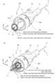
図1、図2を用いて、本実施形態に係る医療システム1A及び医療装置1について説明する。図1は、医療システム1Aの全体図である。図2は医療装置1及び支持台2を示す斜視図である。
<Medical system and medical device>
Amedical system 1A and amedical device 1 according to the present embodiment will be described with reference to FIGS. 1 and 2. FIG. FIG. 1 is an overall view of amedical system 1A. FIG. 2 is a perspective view showing themedical device 1 and thesupport base 2. FIG.

医療システム1Aは、医療装置1と、医療装置1を取り付ける支持台2と、医療装置1を制御する制御部(制御装置)3を備える。本実施形態において、医療システム1Aは、表示装置としてのモニタ4を備える。 Themedical system 1</b>A includes amedical device 1 , asupport base 2 to which themedical device 1 is attached, and a controller (control device) 3 that controls themedical device 1 . In this embodiment, themedical system 1A includes amonitor 4 as a display device.

医療装置1は、湾曲可能体としてのカテーテル11を備えるカテーテルユニット(湾曲可能ユニット)100と、ベースユニット(駆動ユニット、被装着ユニット)200を備える。カテーテルユニット100は、ベースユニット200に対して着脱可能に構成されている。 Themedical device 1 includes a catheter unit (bendable unit) 100 having acatheter 11 as a bendable body, and a base unit (driving unit, wearable unit) 200 . Thecatheter unit 100 is detachably attached to thebase unit 200 .

本実施形態において、医療システム1A及び医療装置1の使用者は、対象の内部にカテーテル11を挿入することにより、対象の内部の観察、対象の内部からの各種検体の採取、対象の内部に対する処置などの作業を行うことができる。一つの実施形態として、使用者は、カテーテル11を対象としての患者の内部に挿入できる。具体的には、患者の口腔もしくは鼻腔を介して気管支に挿入することにより、肺組織の観察、採取、切除等の作業を行うことができる。 In this embodiment, the user of themedical system 1A and themedical device 1 inserts thecatheter 11 into the subject to observe the interior of the subject, collect various specimens from the interior of the subject, and treat the interior of the subject. etc. can be performed. In one embodiment, the user can insert thecatheter 11 into the subject patient. Specifically, by inserting the device into the bronchi through the patient's oral cavity or nasal cavity, operations such as observation, collection, and excision of lung tissue can be performed.

カテーテル11は、上記作業を行うための医療器具をガイドするガイド(シース)として用いることができる。医療器具(ツール)の例としては、内視鏡、鉗子、アブレーション装置などが挙げられる。また、カテーテル11自身が上記の医療器具としての機能を有していてもよく、その場合、カテーテル11は筒状に限らず例えば円柱状であってもよい。 Thecatheter 11 can be used as a guide (sheath) for guiding medical instruments for performing the above operations. Examples of medical instruments (tools) include endoscopes, forceps, ablation devices, and the like. Moreover, thecatheter 11 itself may have a function as the above-described medical device, and in that case, thecatheter 11 is not limited to a cylindrical shape, and may be cylindrical, for example.

本実施形態において、制御部3は、演算装置3a、入力装置3bを含む。入力装置3bは、カテーテル11を操作するための命令や入力を受ける。演算装置3aは、カテーテルを制御するためのプログラムや各種データを記憶するストレージ、ランダムアクセスメモリ、プログラムを実行するための中央処理装置を含む。また、制御部3は、モニタ4に画像を表示するための信号を出力する出力部を備えていてもよい。 In this embodiment, thecontrol unit 3 includes an arithmetic device 3a and an input device 3b. The input device 3 b receives commands and inputs for operating thecatheter 11 . The arithmetic unit 3a includes a storage for storing programs for controlling the catheter and various data, a random access memory, and a central processing unit for executing the programs. Also, thecontrol unit 3 may include an output unit that outputs a signal for displaying an image on themonitor 4 .

図2に示すように、本実施形態では、医療装置1は、医療装置1のベースユニット200と支持台2を連結するケーブル5と支持台2とを介して、制御部3に電気的に接続される。なお、医療装置1と制御部3がケーブルで直接接続されていてもよい。医療装置1と制御部3が無線で接続されていてもよい。 As shown in FIG. 2, in this embodiment, themedical device 1 is electrically connected to thecontrol unit 3 via thesupport base 2 and thecable 5 connecting thebase unit 200 of themedical device 1 and thesupport base 2. be done. Note that themedical device 1 and thecontrol unit 3 may be directly connected by a cable. Themedical device 1 and thecontroller 3 may be wirelessly connected.

医療装置1は、ベースユニット200を介して支持台2に取り外し可能に装着される。より具体的には、医療装置1は、ベースユニット200の取り付け部(接続部)200aが、支持台2の移動ステージ(受け部)2aに取り外し可能に装着される。医療装置1の取り付け部200aが移動ステージ2aから取り外された状態であっても、制御部3によって医療装置1を制御可能なように、医療装置1と制御部3の接続は維持される。本実施形態においては、医療装置1の取り付け部200aが移動ステージ2aから取り外された状態であっても、医療装置1と支持台2は、ケーブル5によって接続されている。 Themedical device 1 is detachably attached to thesupport base 2 via thebase unit 200 . More specifically, in themedical device 1 , the attaching portion (connecting portion) 200 a of thebase unit 200 is detachably attached to the moving stage (receiving portion) 2 a of thesupport base 2 . The connection between themedical device 1 and thecontroller 3 is maintained so that themedical device 1 can be controlled by thecontroller 3 even when themounting portion 200a of themedical device 1 is removed from themoving stage 2a. In this embodiment, themedical device 1 and thesupport base 2 are connected by thecable 5 even when themounting portion 200a of themedical device 1 is removed from themoving stage 2a.

使用者は、医療装置1が支持台2から取り外された状態(医療装置1が、移動ステージ2aから取り外された状態)で医療装置1を手動で移動させ、対象の内部にカテーテル11を挿入することができる。 The user manually moves themedical device 1 in a state in which themedical device 1 is detached from the support base 2 (a state in which themedical device 1 is detached from themoving stage 2a), and inserts thecatheter 11 into the subject. be able to.

使用者は、カテーテル11が対象に挿入され、支持台2に医療装置1が取り付けられた状態で、医療装置1を使用することができる。具体的には、医療装置1が移動ステージ2aに取り付けられた状態で、移動ステージ2aが移動することにより、医療装置1が移動する。そして、カテーテル11を対象に挿入する方向に移動する動作、カテーテル11を対象から引き抜く方向に移動する動作が行われる。移動ステージ2aの移動は、制御部3によって制御される。 The user can use themedical device 1 with thecatheter 11 inserted into the subject and themedical device 1 attached to thesupport base 2 . Specifically, themedical apparatus 1 is moved by moving themovable stage 2a while themedical apparatus 1 is attached to themovable stage 2a. Then, an operation of moving thecatheter 11 in the direction of inserting it into the object and an operation of moving thecatheter 11 in the direction of withdrawing it from the object are performed. The movement of the movingstage 2a is controlled by thecontroller 3. FIG.

ベースユニット200の取り付け部200aは、不図示の解除スイッチと取り外しスイッチを備えている。取り付け部200aが移動ステージ2aに装着された状態で、使用者は、解除スイッチを押し続けながら、医療装置1を移動ステージ2aのガイド方向に沿って手動で移動できる。即ち、移動ステージ2aは、医療装置1の移動を案内するガイド構成を備える。使用者が解除スイッチを押すことを止めると、医療装置1は、移動ステージ2aに固定される。一方、取り付け部200aが移動ステージ2aに装着された状態で取り外しスイッチが押されると、使用者は医療装置1を移動ステージ2aから取り外すことができる。 The mountingportion 200a of thebase unit 200 has a release switch and a removal switch (not shown). With the mountingportion 200a attached to the movingstage 2a, the user can manually move themedical device 1 along the guide direction of the movingstage 2a while continuing to press the release switch. That is, the movingstage 2a has a guide structure that guides the movement of themedical device 1. As shown in FIG. When the user stops pressing the release switch, themedical device 1 is fixed to the movingstage 2a. On the other hand, when the detachment switch is pressed while the mountingportion 200a is attached to the movingstage 2a, the user can detach themedical device 1 from the movingstage 2a.

なお、一つのスイッチが解除スイッチの機能と取り外しスイッチの機能を有していてもよい。また、解除スイッチが押下状態と非押下状態をスイッチングする機構を解除スイッチに設ければ、医療装置1の手動スライド移動時に、使用者は解除スイッチを押下し続ける必要がなくなる。 Note that one switch may have the function of the release switch and the function of the removal switch. Further, if the release switch is provided with a mechanism for switching the release switch between the pressed state and the non-pressed state, the user does not need to keep pressing the release switch when themedical device 1 is manually slid.

取り付け部200aが移動ステージ2aに装着され、解除スイッチ及び取り外しスイッチが押されていない状態では、医療装置1は、移動ステージ2aに固定され、不図示のモータによって駆動される移動ステージ2aによって移動される。 When theattachment part 200a is attached to the movingstage 2a and the release switch and the removal switch are not pressed, themedical device 1 is fixed to the movingstage 2a and moved by the movingstage 2a driven by a motor (not shown). be.

医療装置1は、カテーテル11を駆動するためのワイヤ駆動部(線状部材駆動部、ライン駆動部、本体駆動部)300を備える。本実施形態において、医療装置1は、制御部3によって制御されたワイヤ駆動部300によって、カテーテル11を駆動するロボットカテーテル装置である。 Themedical device 1 includes a wire drive section (linear member drive section, line drive section, body drive section) 300 for driving thecatheter 11 . In this embodiment, themedical device 1 is a robotic catheter device that drives thecatheter 11 by means of awire driving section 300 controlled by thecontrol section 3 .

制御部3は、ワイヤ駆動部300を制御し、カテーテル11を屈曲する動作を行うことができる。本実施形態では、ワイヤ駆動部300は、ベースユニット200に内蔵されている。より具体的には、ベースユニット200は、ワイヤ駆動部300を収納するベース筐体200fを備える。つまり、ベースユニット200は、ワイヤ駆動部300を備えている。ワイヤ駆動部300とベースユニット200を合わせて、カテーテル駆動装置(ベース装置、本体)と呼ぶことができる。 Thecontrol unit 3 can control thewire driving unit 300 to bend thecatheter 11 . In this embodiment, thewire driving section 300 is built into thebase unit 200 . More specifically, thebase unit 200 includes abase housing 200f that houses thewire driving section 300. As shown in FIG. That is, thebase unit 200 includes thewire driving section 300. As shown in FIG. Thewire driving section 300 and thebase unit 200 together can be called a catheter driving device (base device, main body).

カテーテル11の延伸方向について、対象に挿入されるカテーテル11の先端が配置される端部を、遠位端と呼ぶ。カテーテル11の延伸方向について、遠位端の反対側を近位端と呼ぶ。 With respect to the extending direction of thecatheter 11, the end where the tip of thecatheter 11 inserted into the object is arranged is called the distal end. The side opposite to the distal end with respect to the extending direction of thecatheter 11 is called the proximal end.

カテーテルユニット100は、カテーテル11の近位端側をカバーする近位端カバー16を有する。近位端カバー16はツール穴16aを有する。カテーテル11には、ツール穴16aを介して、医療器具を挿入することができる。 Thecatheter unit 100 has aproximal end cover 16 that covers the proximal end side of thecatheter 11 . Theproximal end cover 16 has atool hole 16a. A medical instrument can be inserted into thecatheter 11 through thetool hole 16a.

上述したように、本実施形態において、カテーテル11は、医療器具を対象の内部の所望の位置にガイドするためのガイド装置としての機能を有する。 As described above, in this embodiment, thecatheter 11 functions as a guide device for guiding the medical instrument to the desired position inside the subject.

例えば、カテーテル11に内視鏡を挿入した状態で、対象の内部の目標の位置までカテーテル11を挿入する。このとき、使用者の手動操作、移動ステージ2aの移動、ワイヤ駆動部300によるカテーテル11の駆動の少なくともいずれか一つが用いられる。カテーテル11が目標の位置に到達した後、ツール穴16aを介してカテーテル11から内視鏡が引き抜かれる。そして、ツール穴16aから医療器具を挿入し、対象の内部からの各種検体の採取、対象の内部に対する処置などの作業が行われる。 For example, with an endoscope inserted into thecatheter 11, thecatheter 11 is inserted to a target position inside the subject. At this time, at least one of manual operation by the user, movement of the movingstage 2a, and driving of thecatheter 11 by thewire driving section 300 is used. After thecatheter 11 reaches the target position, the endoscope is withdrawn from thecatheter 11 through thetool hole 16a. Then, a medical instrument is inserted through thetool hole 16a, and various specimens are collected from the inside of the target, and operations such as treatment for the inside of the target are performed.

後述するように、カテーテルユニット100は、カテーテル駆動装置(ベース装置、本体)、より具体的にはベースユニット200に対して取り外し可能に装着される。医療装置1が使用された後に、使用者は、ベースユニット200からカテーテルユニット100を取り外し、新たなカテーテルユニット100をベースユニット200に取り付けて、再び医療装置1を使用することができる。つまり、カテーテルユニット100は、ディスポーザブルなユニットとして使用することができる。ここで、ディスポーザブルとは一度の施術において使用されたカテーテルユニット100は、使用後に廃棄されるという意味である。これにより、カテーテルユニット100の再使用を防止し、常に医療装置1を清潔な状態に保つことができる。 As will be described later, thecatheter unit 100 is detachably attached to a catheter driving device (base device, main body), more specifically thebase unit 200 . After themedical device 1 is used, the user can remove thecatheter unit 100 from thebase unit 200, attach anew catheter unit 100 to thebase unit 200, and use themedical device 1 again. That is,catheter unit 100 can be used as a disposable unit. Here, "disposable" means that thecatheter unit 100 used in one operation is discarded after use. This prevents thecatheter unit 100 from being reused and keeps themedical device 1 clean at all times.

図2に示すように、医療装置1は、操作部400を有する。本実施形態において、操作部400は、カテーテルユニット100に備えられる。操作部400は、ベースユニット200に対するカテーテルユニット100の固定、ベースユニット200からのカテーテルユニット100の取り外しが行われる際に、使用者によって操作される。 As shown in FIG. 2 , themedical device 1 has anoperation section 400 . In this embodiment, theoperating section 400 is provided in thecatheter unit 100 . Theoperation section 400 is operated by the user when fixing thecatheter unit 100 to thebase unit 200 and removing thecatheter unit 100 from thebase unit 200 .

カテーテル11に挿入される内視鏡とモニタ4とを接続することにより、モニタ4に内視鏡によって撮影された画像を表示させることができる。また、モニタ4と制御部3を接続することにより、医療装置1の状態、医療装置1の制御に関連する情報をモニタ4に表示させることができる。例えば、対象の内部におけるカテーテル11の位置や、対象の内部におけるカテーテル11のナビゲーションに関連する情報を、モニタ4に表示させることができる。モニタ4と制御部3及び内視鏡は、有線接続されていてもよく、無線接続されていてもよい。また、モニタ4と制御部3は、支持台2を介して接続されていてもよい。 By connecting the endoscope inserted into thecatheter 11 and themonitor 4 , the image captured by the endoscope can be displayed on themonitor 4 . By connecting themonitor 4 and thecontrol unit 3 , the status of themedical device 1 and information related to the control of themedical device 1 can be displayed on themonitor 4 . For example, the position of thecatheter 11 within the subject and information related to the navigation of thecatheter 11 within the subject can be displayed on themonitor 4 . Themonitor 4, thecontroller 3, and the endoscope may be wired or wirelessly connected. Also, themonitor 4 and thecontrol unit 3 may be connected via thesupport base 2 .

<カテーテル>
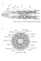
図3(a)(b)を用いて、湾曲可能体としてのカテーテル11について説明する。図3(a)(b)はカテーテル11の説明図である。図3(a)はカテーテル11の全体を説明する図である。図3(b)はカテーテル11の拡大図である。
<Catheter>
Thecatheter 11 as a bendable body will be described with reference to FIGS. 3(a) and 3(b). 3(a) and 3(b) are explanatory diagrams of thecatheter 11. FIG. FIG. 3(a) is a diagram illustrating theentire catheter 11. FIG. FIG. 3(b) is an enlarged view of thecatheter 11. FIG.

カテーテル11は、湾曲部(湾曲体、カテーテル本体)12と、湾曲部12を湾曲するように構成された湾曲駆動部(カテーテル駆動部)13を備える。湾曲駆動部13は、後述する連結装置21を介してワイヤ駆動部300の駆動力を受けて、湾曲部12を湾曲させるように構成される。 Thecatheter 11 includes a bending portion (bending body, catheter main body) 12 and a bending driving portion (catheter driving portion) 13 configured to bend the bendingportion 12 . Thebending driving portion 13 is configured to bend the bendingportion 12 by receiving the driving force of thewire driving portion 300 via the connectingdevice 21 to be described later.

カテーテル11は、対象に対するカテーテル11の挿入方向に沿って延伸されている。カテーテル11の延伸方向(長手方向)は、湾曲部12の延伸方向(長手方向)、後述する第1~第9駆動ワイヤ(W11~W33)の延伸方向(長手方向)と同じである。Catheter 11 is stretched along the direction of insertion ofcatheter 11 into the subject. The extending direction (longitudinal direction) of thecatheter 11 is the same as the extending direction (longitudinal direction) of the bendingportion 12 and the extending direction (longitudinal direction) of first to ninth drive wires (W11 to W33) described later.

湾曲駆動部13は、湾曲部12に接続された複数の駆動ワイヤ(駆動ライン、線状部材、線状アクチュエータ)を含む。具体的には、湾曲駆動部13は、第1駆動ワイヤW11、第2駆動ワイヤW12、第3駆動ワイヤW13、第4駆動ワイヤW21、第5駆動ワイヤW22、第6駆動ワイヤW23、第7駆動ワイヤW31、第8駆動ワイヤW32、第9駆動ワイヤW33を含む。 The bendingdrive section 13 includes a plurality of drive wires (drive lines, linear members, linear actuators) connected to thebending section 12 . Specifically, the bendingdrive unit 13 includes a first drive wire W11, a second drive wire W12, a third drive wire W13, a fourth drive wire W21, a fifth drive wire W22, a sixth drive wire W23, a seventh drive wire W23, and a seventh drive wire W23. It includes a wire W31, an eighth drive wire W32 and a ninth drive wire W33.

第1~第9駆動ワイヤ(W11~W33)のそれぞれは、被保持部(被保持軸、ロッド)Waを含む。具体的には、第1駆動ワイヤW11は第1被保持部Wa11を含む。第2駆動ワイヤW12は第2被保持部Wa12を含む。第3駆動ワイヤW13は第3被保持部Wa13を含む。第4駆動ワイヤW21は第4被保持部Wa21を含む。第5駆動ワイヤW22は第5被保持部Wa22を含む。第6駆動ワイヤW23は第6被保持部Wa23を含む。第7駆動ワイヤW31は第7被保持部Wa31を含む。第8駆動ワイヤW32は第8被保持部Wa32を含む。第9駆動ワイヤW33は第9被保持部Wa33を含む。 Each of the first to ninth drive wires (W11 to W33) includes a held portion (held shaft, rod) Wa. Specifically, the first drive wire W11 includes a first held portion Wa11. The second drive wire W12 includes a second held portion Wa12. The third drive wire W13 includes a third held portion Wa13. The fourth drive wire W21 includes a fourth held portion Wa21. The fifth drive wire W22 includes a fifth held portion Wa22. The sixth drive wire W23 includes a sixth held portion Wa23. The seventh drive wire W31 includes a seventh held portion Wa31. The eighth drive wire W32 includes an eighth held portion Wa32. The ninth drive wire W33 includes a ninth held portion Wa33.

本実施形態において、第1~第9被保持部(Wa11~Wa33)のそれぞれは、同一形状である。 In this embodiment, each of the first to ninth held portions (Wa11 to Wa33) has the same shape.

第1~第9駆動ワイヤ(W11~W33)のそれぞれは、可撓性を有するワイヤ体(ワイヤ部材、ライン体、線状体)Wbを含む。ここでワイヤ体Wbとは、これを介して接続されている物体の押し引きが可能となる部材であって、ある程度の剛性をもっている。一方で、湾曲部12を湾曲させることができるように、直線形状から変形可能な部材である。第1駆動ワイヤW11は第1ワイヤ体Wb11を含む。第2駆動ワイヤW12は第2ワイヤ体Wb12を含む。第3駆動ワイヤW13は第3ワイヤ体Wb13を含む。第4駆動ワイヤW21は第4ワイヤ体Wb21を含む。第5駆動ワイヤW22は第5ワイヤ体Wb22を含む。第6駆動ワイヤW23は第6ワイヤ体Wb23を含む。第7駆動ワイヤW31は第7ワイヤ体Wb31を含む。第8駆動ワイヤW32は第8ワイヤ体Wb32を含む。第9駆動ワイヤW33は第9ワイヤ体Wb33を含む。 Each of the first to ninth drive wires (W11 to W33) includes a flexible wire body (wire member, line body, linear body) Wb. Here, the wire body Wb is a member that enables pushing and pulling of an object connected through the wire body Wb, and has a certain degree of rigidity. On the one hand, it is a member that can be deformed from a linear shape so that the bendingportion 12 can be bent. The first drive wire W11 includes a first wire body Wb11. The second drive wire W12 includes a second wire body Wb12. The third drive wire W13 includes a third wire body Wb13. The fourth drive wire W21 includes a fourth wire body Wb21. The fifth drive wire W22 includes a fifth wire body Wb22. The sixth drive wire W23 includes a sixth wire body Wb23. The seventh drive wire W31 includes a seventh wire body Wb31. The eighth drive wire W32 includes an eighth wire body Wb32. The ninth drive wire W33 includes a ninth wire body Wb33.

本実施形態において、第1~第3ワイヤ体(Wb11~Wb13)のそれぞれは、同一形状である。第4~第6ワイヤ体(Wb21~Wb23)のそれぞれは、同一形状である。第7~第9ワイヤ体(Wb31~Wb33)のそれぞれは、同一形状である。本実施形態では、第1~第9ワイヤ体(Wb11~Wb33)は、長さを除き、同一形状である。 In this embodiment, each of the first to third wire bodies (Wb11 to Wb13) has the same shape. Each of the fourth to sixth wire bodies (Wb21 to Wb23) has the same shape. Each of the seventh to ninth wire bodies (Wb31 to Wb33) has the same shape. In this embodiment, the first to ninth wire bodies (Wb11 to Wb33) have the same shape except for the length.

第1~第9被保持部(Wa11~Wa33)は、第1~第9ワイヤ体(Wb11~Wb33)の近位端に取り付けられている。第1~第9駆動ワイヤ(W11~W33)は、ワイヤガイド17を介して、湾曲部12に挿入され、固定されている。 The first to ninth held portions (Wa11 to Wa33) are attached to the proximal ends of the first to ninth wire bodies (Wb11 to Wb33). The first to ninth drive wires (W11 to W33) are inserted into thebending section 12 through wire guides 17 and fixed.

本実施形態において、第1~第9ワイヤ体(Wb11~Wb33)のそれぞれの材質は金属である。ただし、第1~第9ワイヤ体(Wb11~Wb33)のそれぞれの材質は樹脂でもよい。また、第1~第9ワイヤ体(Wb11~Wb33)のそれぞれの材質が、金属及び樹脂を含んでいてもよい。 In this embodiment, the material of each of the first to ninth wire bodies (Wb11 to Wb33) is metal. However, the material of each of the first to ninth wire bodies (Wb11 to Wb33) may be resin. Also, the material of each of the first to ninth wire bodies (Wb11 to Wb33) may contain metal and resin.

第1~第9駆動ワイヤ(W11~W33)のうち、任意の一つを、線状部材としての駆動ワイヤWと呼ぶことができる。本実施形態において、第1~第9駆動ワイヤ(W11~W33)のそれぞれは、第1~第9ワイヤ体(Wb11~Wb33)の長さを除き、同一形状である。 Any one of the first to ninth drive wires (W11 to W33) can be called a drive wire W as a linear member. In this embodiment, each of the first to ninth drive wires (W11 to W33) has the same shape except for the length of the first to ninth wire bodies (Wb11 to Wb33).

本実施形態において、湾曲部12は、可撓性を有し、医療器具を挿入するための通路Htを備える管状の部材である。 In this embodiment, the bendingportion 12 is a tubular member having flexibility and having a passage Ht for inserting a medical instrument.

湾曲部12の壁面には、第1~第9駆動ワイヤ(W11~W33)のそれぞれを通すための複数のワイヤ穴が備えられる。具体的には、湾曲部12の壁面には、第1ワイヤ穴Hw11、第2ワイヤ穴Hw12、第3ワイヤ穴Hw13が備えられている。さらに湾曲部12の壁面には、第4ワイヤ穴Hw21、第5ワイヤ穴Hw22、第6ワイヤ穴Hw23が備えられている。さらに湾曲部12の壁面には、第7ワイヤ穴Hw31、第8ワイヤ穴Hw32、第9ワイヤ穴Hw33が備えられている。第1~第9ワイヤ穴Hw(Hw11~Hw33)のそれぞれは、第1~第9駆動ワイヤ(W11~W33)のそれぞれに対応する。符号Hwの後の数字は、対応する駆動ワイヤの数字を示す。例えば、第1駆動ワイヤW11は、第1ワイヤ穴Hw11に挿入される。 A wall surface of thecurved portion 12 is provided with a plurality of wire holes for passing the first to ninth drive wires (W11 to W33) respectively. Specifically, the wall surface of thecurved portion 12 is provided with a first wire hole Hw11, a second wire hole Hw12, and a third wire hole Hw13. Furthermore, the wall surface of thecurved portion 12 is provided with a fourth wire hole Hw21, a fifth wire hole Hw22, and a sixth wire hole Hw23. Furthermore, the wall surface of thecurved portion 12 is provided with a seventh wire hole Hw31, an eighth wire hole Hw32, and a ninth wire hole Hw33. The first to ninth wire holes Hw (Hw11 to Hw33) respectively correspond to the first to ninth drive wires (W11 to W33). The number after the symbol Hw indicates the number of the corresponding drive wire. For example, the first drive wire W11 is inserted into the first wire hole Hw11.

第1~第9ワイヤ穴(Hw11~Hw33)のうち、任意の一つを、ワイヤ穴Hwと呼ぶことができる。本実施形態において、第1~第9ワイヤ穴(Hw11~Hw33)のそれぞれは、同一形状である。 Any one of the first to ninth wire holes (Hw11 to Hw33) can be called a wire hole Hw. In this embodiment, each of the first to ninth wire holes (Hw11 to Hw33) has the same shape.

湾曲部12は、中間領域12a、湾曲領域12bを有する。湾曲領域12bは、湾曲部12の遠位端に配置されており、湾曲領域12bには、第1ガイドリングJ1、第2ガイドリングJ2、第3ガイドリングJ3が配置される。湾曲領域12bとは、湾曲駆動部13によって第1ガイドリングJ1、第2ガイドリングJ2、第3ガイドリングJ3を移動させることにより、湾曲部12の屈曲の大きさや方向を制御することができる領域を言う。図3(b)は、第1~第3ガイドリング(J1~J3)を覆う湾曲部12の一部を省略して描かれている。 The bendingportion 12 has anintermediate region 12a and abending region 12b. The bendingregion 12b is arranged at the distal end of thebending section 12, and the first guide ring J1, the second guide ring J2 and the third guide ring J3 are arranged in thebending region 12b. The bendingarea 12b is an area in which the bending magnitude and direction of the bendingportion 12 can be controlled by moving the first guide ring J1, the second guide ring J2, and the third guide ring J3 by the bendingdrive section 13. say. FIG. 3(b) is drawn with a part of thecurved portion 12 covering the first to third guide rings (J1 to J3) omitted.

本実施形態では、湾曲部12は、複数の補助リング(不図示)を備える。湾曲領域12bにおいて、第1ガイドリングJ1、第2ガイドリングJ2、第3ガイドリングJ3は湾曲部12の壁面に固定されている。本実施形態では、複数の補助リングは、第1ガイドリングJ1と第2ガイドリングJ2の間、第2ガイドリングJ2と第3ガイドリングJ3の間に配置される。 In this embodiment, theflexure 12 comprises a plurality of auxiliary rings (not shown). The first guide ring J1, the second guide ring J2, and the third guide ring J3 are fixed to the wall surface of thecurved portion 12 in thecurved region 12b. In this embodiment, the plurality of auxiliary rings are arranged between the first guide ring J1 and the second guide ring J2 and between the second guide ring J2 and the third guide ring J3.

医療器具は、通路Ht、第1~第3ガイドリング(J1~J3)、複数の補助リングによって、カテーテル11の先端までガイドされる。 A medical instrument is guided to the distal end of thecatheter 11 by the passageway Ht, first to third guide rings (J1 to J3), and a plurality of auxiliary rings.

第1~第9駆動ワイヤ(W11~W33)のそれぞれは、中間領域12aを通って第1~第3ガイドリング(J1~J3)のそれぞれに固定されている。具体的には、第1駆動ワイヤW11、第2駆動ワイヤW12、第3駆動ワイヤW13は、第1ガイドリングJ1に固定されている。第4駆動ワイヤW21、第5駆動ワイヤW22、第6駆動ワイヤW23は、第1ガイドリングJ1、複数の補助リングを貫通して、第2ガイドリングJ2に固定されている。第7駆動ワイヤW31、第8駆動ワイヤW32、第9駆動ワイヤW33は、第1ガイドリングJ1、第2ガイドリングJ2、複数の補助リングを貫通して、第3ガイドリングJ3に固定されている。 Each of the first to ninth drive wires (W11 to W33) is fixed to each of the first to third guide rings (J1 to J3) through theintermediate region 12a. Specifically, the first drive wire W11, the second drive wire W12, and the third drive wire W13 are fixed to the first guide ring J1. A fourth drive wire W21, a fifth drive wire W22, and a sixth drive wire W23 pass through the first guide ring J1 and the plurality of auxiliary rings and are fixed to the second guide ring J2. A seventh drive wire W31, an eighth drive wire W32, and a ninth drive wire W33 pass through the first guide ring J1, the second guide ring J2, and the plurality of auxiliary rings, and are fixed to the third guide ring J3. .

医療装置1は、湾曲駆動部13をワイヤ駆動部300によって駆動することにより、カテーテル11の延伸方向に交差する方向に向けて、湾曲部12を湾曲させることができる。具体的には、第1~第9駆動ワイヤ(W11~W33)のそれぞれを湾曲部12の延伸方向に移動させることにより、第1~第3ガイドリング(J1~J3)を介して、湾曲部12の湾曲領域12bを、延伸方向に交差する方向に湾曲させることができる。 Themedical device 1 can bend the bendingportion 12 in a direction intersecting the extending direction of thecatheter 11 by driving thebending driving portion 13 with thewire driving portion 300 . Specifically, by moving each of the first to ninth drive wires (W11 to W33) in the extending direction of the bendingportion 12, the bending portion is moved through the first to third guide rings (J1 to J3). The twelvecurved regions 12b can be curved in a direction transverse to the stretch direction.

使用者は、手動又は移動ステージ2aによる医療装置1の移動、及び湾曲部12の湾曲の少なくともいずれか一つを用いることにより、カテーテル11を対象の内部の目的の部分まで挿入することができる。 The user can insert thecatheter 11 to the target portion inside the subject by using at least one of moving themedical device 1 manually or by the movingstage 2a and bending the bendingportion 12. FIG.

なお、本実施形態においては、第1~第9駆動ワイヤ(W11~W33)によって、第1~第3ガイドリング(J1~J3)を移動して、湾曲部12を屈曲させるが、この構成に限定されない。第1~第3ガイドリング(J1~J3)のいずれか1つ、又は2つと、それに固定される駆動ワイヤを省略してもよい。 In this embodiment, the first to ninth drive wires (W11 to W33) move the first to third guide rings (J1 to J3) to bend the bendingportion 12. Not limited. Any one or two of the first to third guide rings (J1 to J3) and the drive wires fixed thereto may be omitted.

例えば、カテーテル11が、第7~第9駆動ワイヤ(W31~W33)と第3ガイドリングJ3を有し、第1~第6駆動ワイヤ(W11~W23)と、第1~第2ガイドリング(J1~J2)が省略された構成を有していてもよい。また、カテーテル11が、第4~第9駆動ワイヤ(W21~W33)と第2~第3ガイドリング(J2~J3)を有し、第1~第3駆動ワイヤ(W11~W13)と、第1ガイドリングJ1が省略された構成を有していてもよい。 For example, thecatheter 11 has seventh to ninth drive wires (W31 to W33) and a third guide ring J3, first to sixth drive wires (W11 to W23) and first to second guide rings ( J1 to J2) may be omitted. Further, thecatheter 11 has fourth to ninth drive wires (W21 to W33) and second to third guide rings (J2 to J3), and has first to third drive wires (W11 to W13) and a 1 guide ring J1 may have the structure omitted.

また、カテーテル11が1つのガイドリングを二つの駆動ワイヤで駆動する構成であってもよい。この場合も、ガイドリングの数は一つでもよく、一つより多くてもよい。 Alternatively, thecatheter 11 may have a configuration in which one guide ring is driven by two drive wires. Also in this case, the number of guide rings may be one, or more than one.

<カテーテルユニット>
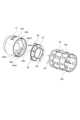
図4(a)(b)を用いて、カテーテルユニット100について説明する。図4(a)(b)はカテーテルユニット100の説明図である。図4(a)は、後述するワイヤカバー14がカバー位置にある状態のカテーテルユニット100の説明図である。図4(b)は、後述するワイヤカバー14が露出位置にある状態のカテーテルユニット100の説明図である。
<Catheter unit>
Thecatheter unit 100 will be described with reference to FIGS. 4(a) and 4(b). 4(a) and 4(b) are explanatory diagrams of thecatheter unit 100. FIG. FIG. 4(a) is an explanatory diagram of thecatheter unit 100 in a state where thewire cover 14, which will be described later, is in the cover position. FIG. 4(b) is an explanatory view of thecatheter unit 100 in which thewire cover 14, which will be described later, is in the exposed position.

カテーテルユニット100は、湾曲部12、湾曲駆動部13を有するカテーテル11、カテーテル11の近位端を支持する近位端カバー16、を有する。カテーテルユニット100は、複数の駆動ワイヤとしての第1~第9駆動ワイヤ(W11~W33)を覆い、保護するためのカバー(ワイヤカバー)14を備える。 Thecatheter unit 100 has a bendingportion 12 , acatheter 11 having abending driving portion 13 , and aproximal end cover 16 supporting the proximal end of thecatheter 11 . Thecatheter unit 100 includes a cover (wire cover) 14 for covering and protecting first to ninth drive wires (W11 to W33) as a plurality of drive wires.

カテーテルユニット100は、ベースユニット200に対して、着脱方向DEに沿って着脱可能である。カテーテルユニット100のベースユニット200に対する装着方向、カテーテルユニット100のベースユニット200からの取り外し方向は、着脱方向DEと平行である。 Thecatheter unit 100 is attachable/detachable with respect to thebase unit 200 along the attachment/detachment direction DE. The direction in which thecatheter unit 100 is attached to thebase unit 200 and the direction in which thecatheter unit 100 is removed from thebase unit 200 are parallel to the attachment/detachment direction DE.

近位端カバー(枠体、湾曲部筐体、カテーテル筐体)16は、カテーテル11の一部を覆うカバーである。近位端カバー16は、湾曲部12の通路Htに医療器具を挿入するためのツール穴16aを有する。 The proximal end cover (frame body, bending portion housing, catheter housing) 16 is a cover that partially covers thecatheter 11 . Theproximal end cover 16 has atool hole 16a for inserting medical instruments into the passageway Ht of theflexure 12 .

ワイヤカバー14には、第1~第9駆動ワイヤ(W11~W33)のそれぞれを通すための複数の露出穴(ワイヤカバー穴、カバー穴)が備えられている。ワイヤカバー14には、第1露出穴14a11、第2露出穴14a12、第3露出穴14a13、第4露出穴14a21、第5露出穴14a22、第6露出穴14a23、第7露出穴14a31、第8露出穴14a32、第9露出穴14a33が備えられている。第1~第9露出穴(14a11~14a33)のそれぞれは、第1~第9駆動ワイヤ(W11~W33)のそれぞれに対応する。符号14aの後の数字は、対応する駆動ワイヤの数字を示す。例えば、第1駆動ワイヤW11は、第1露出穴14a11に挿入される。 Thewire cover 14 is provided with a plurality of exposure holes (wire cover holes, cover holes) through which the first to ninth drive wires (W11 to W33) are passed. Thewire cover 14 has a first exposure hole 14a11, a second exposure hole 14a12, a third exposure hole 14a13, a fourth exposure hole 14a21, a fifth exposure hole 14a22, a sixth exposure hole 14a23, a seventh exposure hole 14a31, and an eighth exposure hole. An exposure hole 14a32 and a ninth exposure hole 14a33 are provided. The first to ninth exposure holes (14a11 to 14a33) respectively correspond to the first to ninth drive wires (W11 to W33). The numbers after the reference numerals 14a indicate the numbers of the corresponding drive wires. For example, the first drive wire W11 is inserted into the first exposure hole 14a11.

第1~第9露出穴(14a11~14a33)のうち、任意の一つを、露出穴14aと呼ぶことができる。本実施形態において、第1~第9露出穴(14a11~14a33)のそれぞれは、同一形状である。 Any one of the first to ninth exposure holes (14a11 to 14a33) can be called an exposure hole 14a. In this embodiment, each of the first to ninth exposure holes (14a11 to 14a33) has the same shape.

ワイヤカバー14は、第1~第9駆動ワイヤ(W11~W33)を覆うカバー位置(図14(a)参照)と、カバー位置から退避したカバー退避位置(図14(b)参照)とに移動できる。カバー退避位置は、第1~第9駆動ワイヤ(W11~W33)を露出させる露出位置と呼ぶこともできる。 The wire cover 14 moves to a cover position (see FIG. 14(a)) covering the first to ninth drive wires (W11 to W33) and a cover retracted position (see FIG. 14(b)) retracted from the cover position. can. The cover retracted position can also be called an exposed position where the first to ninth drive wires (W11 to W33) are exposed.

カテーテルユニット100をベースユニット200に取り付ける前には、ワイヤカバー14はカバー位置に位置する。カテーテルユニット100をベースユニット200に取り付けると、ワイヤカバー14は、着脱方向DEに沿って、カバー位置から露出位置に移動する。 Prior to attachingcatheter unit 100 tobase unit 200,wire cover 14 is in the cover position. When thecatheter unit 100 is attached to thebase unit 200, thewire cover 14 moves from the cover position to the exposed position along the attachment/detachment direction DE.

本実施形態において、ワイヤカバー14は、カバー位置から露出位置に移動した後、露出位置に留められる。したがって、カテーテルユニット100をベースユニット200に取り付けた後、カテーテルユニット100をベースユニット200から取り外しても、ワイヤカバー14は露出位置に留められる。 In this embodiment, thewire cover 14 is retained in the exposed position after being moved from the covered position to the exposed position. Therefore, even if thecatheter unit 100 is removed from thebase unit 200 after attaching thecatheter unit 100 to thebase unit 200, thewire cover 14 is kept in the exposed position.

しかし、ワイヤカバー14を、カバー位置から露出位置に移動した後、カバー位置に戻るように構成してもよい。例えば、カテーテルユニット100が、ワイヤカバー14を露出位置からカバー位置に向けて付勢する付勢部材を備えていてもよい。この場合、カテーテルユニット100をベースユニット200に取り付けた後、カテーテルユニット100をベースユニット200から取り外すと、ワイヤカバー14は露出位置からカバー位置に移動される。 However, thewire cover 14 may be configured to return to the cover position after being moved from the cover position to the exposed position. For example,catheter unit 100 may include a biasing member that biases wire cover 14 from the exposed position toward the covered position. In this case, when thecatheter unit 100 is removed from thebase unit 200 after attaching thecatheter unit 100 to thebase unit 200, thewire cover 14 is moved from the exposed position to the covered position.

ワイヤカバー14が露出位置にあるとき、第1~第9駆動ワイヤ(W11~W33)の第1~第9被保持部(Wa11~Wa33)が露出される。その結果、湾曲駆動部13と後述する連結装置21との連結が許容される。ワイヤカバー14が露出位置にあるとき、第1~第9露出穴(14a11~14a33)から第1~第9駆動ワイヤ(W11~W33)の第1~第9被保持部(Wa11~Wa33)及びワイヤ体Wbの一部が突出する。より具体的には、第1~第9被保持部(Wa11~Wa33)は、後述する取付け方向Daに向けて、第1~第9露出穴(14a11~14a33)から突出する。 When thewire cover 14 is at the exposed position, the first to ninth held portions (Wa11 to Wa33) of the first to ninth drive wires (W11 to W33) are exposed. As a result, connection between the bendingdrive section 13 and a connectingdevice 21, which will be described later, is permitted. When thewire cover 14 is in the exposed position, the first to ninth held portions (Wa11 to Wa33) of the first to ninth drive wires (W11 to W33) through the first to ninth exposure holes (14a11 to 14a33) and A portion of the wire body Wb protrudes. More specifically, the first to ninth held portions (Wa11 to Wa33) protrude from the first to ninth exposure holes (14a11 to 14a33) in the mounting direction Da, which will be described later.

図4(b)に示すように、第1~第9駆動ワイヤ(W11~W33)のそれぞれは、所定の半径を有する円(仮想円)に沿って並べられ、ワイヤガイド17により支持されている。 As shown in FIG. 4B, the first to ninth drive wires (W11 to W33) are arranged along a circle (virtual circle) having a predetermined radius and are supported by thewire guide 17. .

本実施形態では、カテーテルユニット100は、キーシャフト(キー、カテーテル側キー)15を有する。本実施形態では、キーシャフト15は、着脱方向DEに向けて延びている。ワイヤカバー14には、キーシャフト15が貫通するシャフト穴14bが備えられる。キーシャフト15は、後述するキー受け部22と係合可能である。キーシャフト15がキー受け部22と係合することにより、第1~第9駆動ワイヤ(W11~W33)が並べられる円(仮想円)の周方向について、ベースユニット200に対するカテーテルユニット100の移動が、所定の範囲で制限される。 In this embodiment, thecatheter unit 100 has a key shaft (key, catheter side key) 15 . In this embodiment, thekey shaft 15 extends in the attachment/detachment direction DE. Thewire cover 14 is provided with ashaft hole 14b through which thekey shaft 15 passes. Thekey shaft 15 can be engaged with akey receiving portion 22, which will be described later. By engaging thekey shaft 15 with thekey receiving portion 22, the movement of thecatheter unit 100 with respect to thebase unit 200 is achieved in the circumferential direction of the circle (virtual circle) in which the first to ninth drive wires (W11 to W33) are arranged. , is limited to a given range.

本実施形態では、着脱方向DEに見たときに、第1~第9駆動ワイヤ(W11~W33)は、キーシャフト15を囲むように、キーシャフト15の外側に配置されている。言い換えれば、キーシャフト15は、第1~第9駆動ワイヤ(W11~W33)が並べられる円(仮想円)の内側に配置される。したがって、キーシャフト15と第1~第9駆動ワイヤ(W11~W33)を省スペースで配置できる。 In this embodiment, the first to ninth drive wires (W11 to W33) are arranged outside thekey shaft 15 so as to surround thekey shaft 15 when viewed in the attachment/detachment direction DE. In other words, thekey shaft 15 is arranged inside a circle (virtual circle) in which the first to ninth drive wires (W11 to W33) are arranged. Therefore, thekey shaft 15 and the first to ninth drive wires (W11 to W33) can be arranged in a space-saving manner.

本実施形態では、カテーテルユニット100は、操作部400を備える。操作部400は、近位端カバー16、湾曲駆動部13に対して移動可能(回転可能)に構成されている。操作部400は、回転軸400rの周りに回転可能である。操作部400の回転軸400rは、着脱方向DEに向けて延びている。 In this embodiment, thecatheter unit 100 has anoperation section 400 . Theoperation section 400 is configured to be movable (rotatable) with respect to theproximal end cover 16 and the bendingdrive section 13 . Theoperation unit 400 is rotatable around arotation axis 400r. Arotating shaft 400r of theoperation unit 400 extends in the attachment/detachment direction DE.

カテーテルユニット100がベースユニット200に取り付けられた状態で、操作部400は、ベースユニット200に対して移動可能(回転可能)に構成されている。より具体的には、操作部400は、ベース筐体200f、ワイヤ駆動部300、後述する連結装置21に対して移動可能(回転可能)に構成されている。 With thecatheter unit 100 attached to thebase unit 200 , theoperation section 400 is configured to be movable (rotatable) with respect to thebase unit 200 . More specifically, theoperation unit 400 is configured to be movable (rotatable) with respect to thebase housing 200f, thewire driving unit 300, and the connectingdevice 21, which will be described later.

なお、本実施形態において、図4(a)(b)に示すように湾曲部12の延伸方向(長手方向)をZ方向と定義する。また、Z方向に直交し、湾曲部12の中心と被保持部Wa11の中心を結ぶ直線の方向をY方向と定義する。また、Z方向およびY方向に直交する直線の方向をX方向と定義する。なお、X方向、Y方向及びZ方向のそれぞれの方向の内、図4(a)(b)に示すように、一方側を+方向、他方側を-方向とする。また、Z方向は、後述する図6(a)に示す移動方向としてのDc方向と平行である。 In addition, in this embodiment, as shown in FIGS. 4A and 4B, the extending direction (longitudinal direction) of the bendingportion 12 is defined as the Z direction. Further, the direction of a straight line perpendicular to the Z direction and connecting the center of thecurved portion 12 and the center of the held portion Wa11 is defined as the Y direction. Also, the direction of a straight line orthogonal to the Z direction and the Y direction is defined as the X direction. As shown in FIGS. 4(a) and 4(b), one of the X, Y and Z directions is the + direction and the other is the - direction. Also, the Z direction is parallel to the Dc direction as the movement direction shown in FIG. 6A, which will be described later.

<ベースユニット>
図5(a)~(c)を用いて、ベースユニット200及びワイヤ駆動部300について説明する。図5(a)~(c)はベースユニット200及びワイヤ駆動部300の説明図である。図5(a)は、ベースユニット200の内部構造を示す斜視図である。図5(b)は、ベースユニット200の内部構造を示す側面図である。図5(c)は、ベースユニット200を着脱方向DEに沿って見た図である。
<Base unit>
Thebase unit 200 and thewire driving section 300 will be described with reference to FIGS. 5(a) to 5(c). 5A to 5C are explanatory diagrams of thebase unit 200 and thewire driving section 300. FIG. FIG. 5(a) is a perspective view showing the internal structure of thebase unit 200. FIG. FIG. 5B is a side view showing the internal structure of thebase unit 200. FIG. FIG. 5(c) is a diagram of thebase unit 200 viewed along the attachment/detachment direction DE.

上述のように、医療装置1は、ベースユニット200と、ワイヤ駆動部300を有する。本実施形態において、ワイヤ駆動部300は、ベース筐体200fに収納され、ベースユニット200の内部に備えられる。言い換えれば、ベースユニット200は、ワイヤ駆動部300を備える。 As described above, themedical device 1 has thebase unit 200 and thewire driving section 300 . In the present embodiment, thewire driving section 300 is accommodated in thebase housing 200f and provided inside thebase unit 200 . In other words, thebase unit 200 has thewire drive section 300 .

ワイヤ駆動部300は、複数の駆動源(モータ、アクチュエータ)を有する。本実施形態では、ワイヤ駆動部300は、第1駆動源M11、第2駆動源M12、第3駆動源M13、第4駆動源M21、第5駆動源M22、第6駆動源M23、第7駆動源M31、第8駆動源M32、第9駆動源M33を備える。 Thewire drive unit 300 has a plurality of drive sources (motors, actuators). In this embodiment, thewire driving section 300 includes a first driving source M11, a second driving source M12, a third driving source M13, a fourth driving source M21, a fifth driving source M22, a sixth driving source M23, a seventh driving source It has a source M31, an eighth drive source M32, and a ninth drive source M33.

第1~第9駆動源(M11~M33)のうち、任意の一つを、駆動源Mと呼ぶことができる。本実施形態において、第1~第9駆動源(M11~M33)のそれぞれは、同一構成である。 Any one of the first to ninth driving sources (M11 to M33) can be called a driving source M. In this embodiment, each of the first to ninth drive sources (M11 to M33) has the same configuration.

ベースユニット200は、連結装置21を備える。連結装置21は、ベース筐体200fに収納されている。連結装置21は、ワイヤ駆動部300に接続されている。連結装置21は、複数の連結部を有する。本実施形態では、連結装置21は第1連結部21c11、第2連結部21c12、第3連結部21c13、第4連結部21c21、第5連結部21c22、第6連結部21c23、第7連結部21c31、第8連結部21c32、第9連結部21c33を備える。 Thebase unit 200 has acoupling device 21 . Thecoupling device 21 is housed in thebase housing 200f. Thecoupling device 21 is connected to thewire driving section 300 . The connectingdevice 21 has a plurality of connecting parts. In this embodiment, the connectingdevice 21 includes a first connecting portion 21c11, a second connecting portion 21c12, a third connecting portion 21c13, a fourth connecting portion 21c21, a fifth connecting portion 21c22, a sixth connecting portion 21c23, and a seventh connecting portion 21c31. , an eighth connecting portion 21c32 and a ninth connecting portion 21c33.

第1~第9連結部(21c11~21c33)のうち、任意の一つを、連結部21cと呼ぶことができる。本実施形態において、第1~第9連結部(21c11~21c33)のそれぞれは、同一構成である。 Any one of the first to ninth connecting portions (21c11 to 21c33) can be called a connectingportion 21c. In this embodiment, each of the first to ninth connecting portions (21c11 to 21c33) has the same configuration.

複数の連結部のそれぞれは、複数の駆動源のそれぞれに接続され、複数の駆動源のそれぞれによって駆動される。具体的には、第1連結部21c11は、第1駆動源M11に接続され、第1駆動源M11によって駆動される。第2連結部21c12は、第2駆動源M12に接続され、第2駆動源M12によって駆動される。第3連結部21c13は、第3駆動源M13に接続され、第3駆動源M13によって駆動される。第4連結部21c21は、第4駆動源M21に接続され、第4駆動源M21によって駆動される。第5連結部21c22は、第5駆動源M22に接続され、第5駆動源M22によって駆動される。第6連結部21c23は、第6駆動源M23に接続され、第6駆動源M23によって駆動される。第7連結部21c31は、第7駆動源M31に接続され、第7駆動源M31によって駆動される。第8連結部21c32は、第8駆動源M32に接続され、第8駆動源M32によって駆動される。第9連結部21c33は、第9駆動源M33に接続され、第9駆動源M33によって駆動される。 Each of the plurality of connecting portions is connected to each of the plurality of driving sources and driven by each of the plurality of driving sources. Specifically, the first connecting portion 21c11 is connected to the first driving source M11 and driven by the first driving source M11. The second connecting portion 21c12 is connected to the second drive source M12 and driven by the second drive source M12. The third connecting portion 21c13 is connected to the third driving source M13 and driven by the third driving source M13. The fourth connecting portion 21c21 is connected to the fourth driving source M21 and driven by the fourth driving source M21. The fifth connecting portion 21c22 is connected to the fifth driving source M22 and driven by the fifth driving source M22. The sixth connecting portion 21c23 is connected to the sixth driving source M23 and driven by the sixth driving source M23. The seventh connecting portion 21c31 is connected to the seventh driving source M31 and driven by the seventh driving source M31. The eighth connecting portion 21c32 is connected to the eighth driving source M32 and driven by the eighth driving source M32. The ninth connecting portion 21c33 is connected to the ninth driving source M33 and driven by the ninth driving source M33.

後述するように、連結装置21には、第1~第9駆動ワイヤ(W11~W33)を含む湾曲駆動部13が連結される。湾曲駆動部13は、連結装置21を介してワイヤ駆動部300の駆動力を受け、湾曲部12を湾曲させる。 As will be described later, thecoupling device 21 is coupled with the bendingdrive section 13 including first through ninth drive wires (W11 through W33). Thebending driving portion 13 receives the driving force of thewire driving portion 300 via the connectingdevice 21 and bends the bendingportion 12 .

駆動ワイヤWは、被連結部としての被保持部Waを介して連結部21cに連結可能に構成される。複数の駆動ワイヤのそれぞれは、複数の連結部のそれぞれに連結される。具体的には、第1駆動ワイヤW11の第1被保持部Wa11は、第1連結部21c11に連結される。第2駆動ワイヤW12の第2被保持部Wa12は、第2連結部21c12に連結される。第3駆動ワイヤW13の第3被保持部Wa13は、第3連結部21c13に連結される。第4駆動ワイヤW21の第4被保持部Wa21は、第4連結部21c21に連結される。第5駆動ワイヤW22の第5被保持部Wa22は、第5連結部21c22に連結される。第6駆動ワイヤW23の第6被保持部Wa23は、第6連結部21c23に連結される。第7駆動ワイヤW31の第7被保持部Wa31は、第7連結部21c31に連結される。第8駆動ワイヤW32の第8被保持部Wa32は、第8連結部21c32に連結される。第9駆動ワイヤW33の第9被保持部Wa33は、第9連結部21c33に連結される。 The drive wire W is configured to be connectable to the connectingportion 21c via the held portion Wa as a connected portion. Each of the plurality of drive wires is connected to each of the plurality of connecting portions. Specifically, the first held portion Wa11 of the first drive wire W11 is connected to the first connecting portion 21c11. The second held portion Wa12 of the second drive wire W12 is connected to the second connecting portion 21c12. The third held portion Wa13 of the third drive wire W13 is connected to the third connecting portion 21c13. The fourth held portion Wa21 of the fourth drive wire W21 is connected to the fourth connecting portion 21c21. The fifth held portion Wa22 of the fifth drive wire W22 is connected to the fifth connecting portion 21c22. The sixth held portion Wa23 of the sixth drive wire W23 is connected to the sixth connecting portion 21c23. The seventh held portion Wa31 of the seventh drive wire W31 is connected to the seventh connecting portion 21c31. The eighth held portion Wa32 of the eighth drive wire W32 is connected to the eighth connecting portion 21c32. The ninth held portion Wa33 of the ninth drive wire W33 is connected to the ninth connecting portion 21c33.

ベースユニット200は、ベースフレーム25を有する。ベースフレーム25には、第1~第9駆動ワイヤ(W11~W33)のそれぞれを通すための複数の挿入穴が備えられている。ベースフレーム25には第1挿入穴25a11、第2挿入穴25a12、第3挿入穴25a13、第4挿入穴25a21、第5挿入穴25a22、第6挿入穴25a23、第7挿入穴25a31、第8挿入穴25a32、第9挿入穴25a33が備えられている。第1~第9挿入穴(25a11~25a33)のそれぞれは、第1~第9駆動ワイヤ(W11~W33)のそれぞれに対応する。符号25aの後の数字は、対応する駆動ワイヤの数字を示す。例えば、第1駆動ワイヤW11は、第1挿入穴25a11に挿入される。Base unit 200 has abase frame 25 . Thebase frame 25 is provided with a plurality of insertion holes through which the first to ninth drive wires (W11 to W33) are passed. Thebase frame 25 has a first insertion hole 25a11, a second insertion hole 25a12, a third insertion hole 25a13, a fourth insertion hole 25a21, a fifth insertion hole 25a22, a sixth insertion hole 25a23, a seventh insertion hole 25a31, and an eighth insertion hole. A hole 25a32 and a ninth insertion hole 25a33 are provided. The first to ninth insertion holes (25a11 to 25a33) respectively correspond to the first to ninth drive wires (W11 to W33). The numbers after the reference numerals 25a indicate the numbers of the corresponding drive wires. For example, the first drive wire W11 is inserted into the first insertion hole 25a11.

第1~第9挿入穴(25a11~25a33)のうち、任意の一つを、挿入穴25aと呼ぶことができる。本実施形態において、第1~第9挿入穴(25a11~25a33)のそれぞれは、同一形状である。 Any one of the first to ninth insertion holes (25a11 to 25a33) can be called an insertion hole 25a. In this embodiment, each of the first to ninth insertion holes (25a11 to 25a33) has the same shape.

ベースフレーム25には、ワイヤカバー14が挿入される取付け開口25bが備えられる。取付け開口25bの底部に、第1~第9挿入穴(25a11~25a33)が配置されている。 Thebase frame 25 is provided with a mountingopening 25b into which thewire cover 14 is inserted. First to ninth insertion holes (25a11 to 25a33) are arranged at the bottom of the mountingopening 25b.

さらに、ベースユニット200は、モータフレーム200b、第1ベアリングフレーム200c、第2ベアリングフレーム200d、第3ベアリングフレーム200eを備える。モータフレーム200b、第1ベアリングフレーム200c、第2ベアリングフレーム200d、第3ベアリングフレーム200eは、連結されている。 Further, thebase unit 200 includes amotor frame 200b, afirst bearing frame 200c, asecond bearing frame 200d and athird bearing frame 200e. Themotor frame 200b, thefirst bearing frame 200c, thesecond bearing frame 200d and thethird bearing frame 200e are connected.

ベースフレーム25は、キーシャフト15を受け入れるキー受け部(キー穴、ベース側キー、本体側キー)22を有する。キーシャフト15とキー受け部22が係合することにより、カテーテルユニット100がベースユニット200に対して誤った位相で取り付けられることが防止される。 Thebase frame 25 has a key receiving portion (key hole, base side key, body side key) 22 for receiving thekey shaft 15 . The engagement between thekey shaft 15 and thekey receiving portion 22 prevents thecatheter unit 100 from being attached to thebase unit 200 out of phase.

キーシャフト15とキー受け部22が係合することにより、第1~第9駆動ワイヤ(W11~W33)のそれぞれが並べられる円(仮想円)の周方向について、ベースユニット200に対するカテーテルユニット100の移動が、所定の範囲で制限される。 By engaging thekey shaft 15 and thekey receiving portion 22, thecatheter unit 100 is shifted with respect to thebase unit 200 in the circumferential direction of the circle (virtual circle) in which the first to ninth drive wires (W11 to W33) are arranged. Movement is restricted within a predetermined range.

その結果、第1~第9駆動ワイヤ(W11~W33)のそれぞれは、対応する第1~第9挿入穴(25a11~25a33)のそれぞれ、対応する第1~第9連結部(21c11~21c33)のそれぞれに係合する。言い換えれば、駆動ワイヤWが、対応する挿入穴25aと異なる挿入穴25a、対応する連結部21cと異なる21cに係合することが防止される。 As a result, each of the first to ninth drive wires (W11 to W33) is inserted into the corresponding first to ninth insertion holes (25a11 to 25a33) and the corresponding first to ninth connecting portions (21c11 to 21c33). , respectively. In other words, the drive wire W is prevented from engaging with the insertion hole 25a different from the corresponding insertion hole 25a and with the connectingportion 21c different from thecorresponding connection portion 21c.

使用者は、キーシャフト15とキー受け部22とを係合させることで、第1~第9駆動ワイヤ(W11~W33)のそれぞれを、第1~第9連結部(21c11~21c33)のそれぞれに正しく連結できる。したがって、使用者は、カテーテルユニット100をベースユニット200に容易に装着できる。 By engaging thekey shaft 15 and thekey receiving portion 22, the user connects the first to ninth drive wires (W11 to W33) to the first to ninth connecting portions (21c11 to 21c33), respectively. can be correctly concatenated to Therefore, the user can easily attach thecatheter unit 100 to thebase unit 200 .

本実施形態において、キーシャフト15は、着脱方向DEに交差する方向に突出した凸部を有し、キー受け部22は凸部が挿入される凹部を備える。周方向において、凸部と凹部が係合する位置が、駆動ワイヤWが対応する挿入穴25a及び対応する連結部21cと係合する位置である。 In this embodiment, thekey shaft 15 has a convex portion that protrudes in a direction intersecting the attachment/detachment direction DE, and thekey receiving portion 22 has a concave portion into which the convex portion is inserted. In the circumferential direction, the position where the protrusion and the recess are engaged is the position where the drive wire W is engaged with the corresponding insertion hole 25a and the corresponding connectingpart 21c.

なお、キーシャフト15をベースユニット200とカテーテルユニット100のいずれか一方に配置し、キー受け部22をいずれか他方に配置することができる。例えば、キーシャフト15をベースユニット200側に配置し、キー受け部22をカテーテルユニット100側に配置してもよい。 Note that thekey shaft 15 can be arranged on either thebase unit 200 or thecatheter unit 100, and thekey receiving portion 22 can be arranged on the other. For example, thekey shaft 15 may be arranged on thebase unit 200 side and thekey receiving portion 22 may be arranged on thecatheter unit 100 side.

更に、ベースユニット200は、ジョイント係合部28jを備えるジョイント28を有する。ベースフレーム25は、ロック突起26aを備えるロック軸26を有する。これらの機能については、後述する。 Further, thebase unit 200 has a joint 28 with a jointengaging portion 28j. Thebase frame 25 has alock shaft 26 with alock projection 26a. These functions will be described later.

<モータと駆動ワイヤの連結>
図6(a)~(c)を用いて、ワイヤ駆動部300、連結装置21、湾曲駆動部13の連結について説明する。図6(a)~(c)は、ワイヤ駆動部300、連結装置21、湾曲駆動部13の説明図である。図6(a)は、駆動源M、連結部21c、駆動ワイヤWの斜視図である。図6(b)は、連結部21c、駆動ワイヤWの拡大図である。図6(c)は、ワイヤ駆動部300、連結装置21、湾曲駆動部13の連結を示す斜視図である。
<Connection of motor and drive wire>
The connection between thewire driving section 300, the connectingdevice 21, and thebending driving section 13 will be described with reference to FIGS. 6(a) to 6(c). 6A to 6C are explanatory diagrams of thewire driving section 300, thecoupling device 21, and thebending driving section 13. FIG. FIG. 6(a) is a perspective view of the drive source M, the connectingportion 21c, and the drive wire W. FIG. 6B is an enlarged view of the connectingportion 21c and the drive wire W. FIG. FIG. 6C is a perspective view showing the connection of thewire driving section 300, the connectingdevice 21, and thebending driving section 13. FIG.

本実施形態において、第1~第9駆動ワイヤ(W11~W33)のそれぞれと第1~第9連結部(21c11~21c33)のそれぞれが連結される構成は、同一である。また、第1~第9連結部(21c11~21c33)のそれぞれと第1~第9駆動源(M11~M33)のそれぞれが接続される構成は、同一である。従って、以下の説明では、一つの駆動ワイヤW、一つの連結部21c、一つの駆動源Mを用いて、これらが接続される構成について説明する。 In the present embodiment, the structures in which the first to ninth driving wires (W11 to W33) and the first to ninth connecting portions (21c11 to 21c33) are connected are the same. Also, the configuration in which each of the first to ninth connecting portions (21c11 to 21c33) and each of the first to ninth driving sources (M11 to M33) are connected is the same. Therefore, in the following description, one driving wire W, one connectingportion 21c, and one driving source M are used, and a configuration in which these are connected will be described.

図6(a)に示すように、駆動源Mは、出力軸Maと、出力軸Maを回転方向Rmに回転させるモータ本体Mbを有する。出力軸Maの表面には、螺旋状の溝が備えられている。出力軸Maは、所謂ネジ形状を有する。モータ本体Mbは、モータフレーム200bに固定されている。 As shown in FIG. 6A, the drive source M has an output shaft Ma and a motor body Mb that rotates the output shaft Ma in the rotation direction Rm. A spiral groove is provided on the surface of the output shaft Ma. The output shaft Ma has a so-called screw shape. The motor main body Mb is fixed to themotor frame 200b.

連結部21cは、出力軸Maに接続されたトラクタ21ct、トラクタ21ctを支持するトラクタ支持軸21csを有する。トラクタ支持軸21csは、連結ベース21cbに接続されている。 The connectingportion 21c has a tractor 21ct connected to the output shaft Ma and a tractor support shaft 21cs that supports the tractor 21ct. The tractor support shaft 21cs is connected to the connection base 21cb.

連結部21cは、駆動ワイヤWの被保持部Waを押圧するための回転体21cpを有する。駆動ワイヤWは挿入穴25aを通って連結部21cに係合している。詳細は後述するが、回転体21cpは、連結ベース21cbによって回転軸21cpcを中心に回転可能に支持される。そして、回転体21cpは、被保持部Waを連結ベース21cbに向かって押圧して連結ベース21cbに対して係合させることで固定する状態(固定状態)と、被保持部Waを解放した状態(解放状態)とを取ることができる。回転軸21cpcは、本実施形態ではZ方向(Dc方向)に平行に延びているが、Z方向(Dc方向)に沿って延びていればよい。 The connectingportion 21c has a rotating body 21cp for pressing the held portion Wa of the drive wire W. As shown in FIG. The drive wire W passes through the insertion hole 25a and is engaged with the connectingportion 21c. Although the details will be described later, the rotating body 21cp is rotatably supported by the connecting base 21cb around the rotating shaft 21cpc. The rotating body 21cp is fixed by pressing the held portion Wa toward the connecting base 21cb to engage with the connecting base 21cb (fixed state), and in a state in which the held portion Wa is released ( release state). Although the rotating shaft 21cpc extends parallel to the Z direction (Dc direction) in this embodiment, it may extend along the Z direction (Dc direction).

回転体21cpは、後述する内歯ギア29と噛み合うギア部21cgと、駆動ワイヤWの被保持部Waを押圧するための押圧部としてのカム21ccと、を有している。後述するように、カム21ccは、被保持部Waに対して移動することができる。カム21ccが移動することにより、被保持部Waを、連結部21cに固定される固定状態と、連結部21cへの固定が解除される解除状態と、に切り替えることができる。 The rotating body 21cp has a gear portion 21cg that meshes with aninternal gear 29, which will be described later, and a cam 21cc as a pressing portion for pressing the held portion Wa of the drive wire W. As will be described later, the cam 21cc can move with respect to the held portion Wa. By moving the cam 21cc, the held portion Wa can be switched between a fixed state in which it is fixed to the connectingportion 21c and a released state in which the fixation to the connectingportion 21c is released.

連結部21cは、第1ベアリングB1、第2ベアリングB2,第3ベアリングB3によって支持されている。第1ベアリングB1は、ベースユニット200の第1ベアリングフレーム200cに支持されている。第2ベアリングB2は、ベースユニット200の第2ベアリングフレーム200dに支持されている。第3ベアリングB3は、ベースユニット200の第3ベアリングフレーム200eに支持されている。したがって、出力軸Maが回転方向Rmに回転したときに、連結部21cは、出力軸Maの周りに回転することが規制される。なお、第1ベアリングB1、第2ベアリングB2,第3ベアリングB3は、第1~第9連結部(21c11~21c33)のそれぞれに対して設けられる。 The connectingportion 21c is supported by a first bearing B1, a second bearing B2 and a third bearing B3. The first bearing B1 is supported by thefirst bearing frame 200c of thebase unit 200. As shown in FIG. The second bearing B2 is supported by thesecond bearing frame 200d of thebase unit 200. As shown in FIG. The third bearing B3 is supported by thethird bearing frame 200e of thebase unit 200. As shown in FIG. Therefore, when the output shaft Ma rotates in the rotation direction Rm, the connectingportion 21c is restricted from rotating around the output shaft Ma. The first bearing B1, the second bearing B2, and the third bearing B3 are provided for each of the first to ninth connecting portions (21c11 to 21c33).

連結部21cが出力軸Maの周りに回転することが規制されているため、出力軸Maが回転すると、出力軸Maの螺旋状の溝によって、トラクタ21ctに出力軸Maの回転軸方向に沿った力が作用する。その結果、連結部21cは、出力軸Maの回転軸線方向に沿って移動する(Dc方向)。連結部21cが移動することにより、駆動ワイヤWが移動して、湾曲部12が湾曲する。このとき、駆動源Mの回転方向を切り替えることにより、連結部21cは、駆動ワイヤWを押圧する方向及び駆動ワイヤWを引っ張る方向のいずれにも駆動ワイヤWを駆動可能である。 Since the connectingportion 21c is restricted from rotating around the output shaft Ma, when the output shaft Ma rotates, the helical groove of the output shaft Ma causes the tractor 21ct to rotate along the rotation axis direction of the output shaft Ma. force acts. As a result, the connectingportion 21c moves along the rotation axis direction of the output shaft Ma (the Dc direction). As the connectingportion 21c moves, the drive wire W moves and the bendingportion 12 bends. At this time, by switching the rotation direction of the drive source M, theconnection part 21c can drive the drive wire W in both the direction of pushing the drive wire W and the direction of pulling the drive wire W.

つまり、出力軸Maとトラクタ21ctは、駆動源Mから伝えられた回転運動をねじにより直線運動に変換させる、所謂送りねじを構成している。本実施形態において、出力軸Maとトラクタ21ctは滑りネジであるが、ボールねじでも良い。 In other words, the output shaft Ma and the tractor 21ct constitute a so-called feed screw that converts rotary motion transmitted from the drive source M into linear motion by means of a screw. In this embodiment, the output shaft Ma and the tractor 21ct are sliding screws, but they may be ball screws.

図6(c)に示すように、カテーテルユニット100をベースユニット200に取り付けることで、第1~第9駆動ワイヤ(W11~W33)のそれぞれと第1~第9連結部(21c11~21c33)のそれぞれが連結される。 As shown in FIG. 6(c), by attaching thecatheter unit 100 to thebase unit 200, each of the first to ninth drive wires (W11 to W33) and the first to ninth connecting portions (21c11 to 21c33) are connected. are linked together.

制御部3は、第1~第9駆動源(M11~M33)のそれぞれを、互いに対して独立して制御できる。つまり、第1~第9駆動源(M11~M33)のうちの任意の駆動源は、その他の駆動源が停止した状態しているか否かに関わらず、独立して動作すること又は停止することができる。言い換えれば、制御部3は、第1~第9駆動ワイヤ(W11~W33)のそれぞれを、互いに対して独立して制御することができる。その結果、第1~第3ガイドリング(J1~J3)のそれぞれが互いに対して独立して制御され、湾曲部12の湾曲領域12bは、任意の方向に屈曲することができる。 Thecontrol unit 3 can control each of the first to ninth driving sources (M11 to M33) independently of each other. That is, any one of the first to ninth drive sources (M11 to M33) can operate or stop independently regardless of whether the other drive sources are in a stopped state. can be done. In other words, thecontroller 3 can control each of the first to ninth drive wires (W11 to W33) independently of each other. As a result, each of the first to third guide rings (J1 to J3) is controlled independently of each other, allowing the bendingregion 12b of the bendingportion 12 to bend in any direction.

<カテーテルユニットの装着>
図7(a)(b)を用いて、カテーテルユニット100を、ベースユニット200に装着する動作について説明する。図7(a)(b)は、カテーテルユニット100の装着の説明図である。図7(a)は、カテーテルユニット100がベースユニット200に装着される前の図である。図7(b)は、カテーテルユニット100がベースユニット200に装着された後の図である。
<Attaching the catheter unit>
The operation of attaching thecatheter unit 100 to thebase unit 200 will be described with reference to FIGS. 7(a) and 7(b). 7(a) and 7(b) are explanatory views of the attachment of thecatheter unit 100. FIG. FIG. 7(a) is a view before thecatheter unit 100 is attached to thebase unit 200. FIG. FIG. 7B is a diagram after thecatheter unit 100 is attached to thebase unit 200. FIG.

本実施形態において、カテーテルユニット100の着脱方向DEは、操作部400の回転軸400rの方向と同じである。着脱方向DEのうち、カテーテルユニット100をベースユニット200に取り付ける方向を、取り付け方向Daと呼ぶ。着脱方向DEのうち、カテーテルユニット100をベースユニット200から取り外す方向(取付け方向Daの反対方向)を、取り外し方向Ddと呼ぶ。 In this embodiment, the attachment/detachment direction DE of thecatheter unit 100 is the same as the direction of therotating shaft 400r of theoperation section 400. As shown in FIG. Of the attachment/detachment direction DE, the direction in which thecatheter unit 100 is attached to thebase unit 200 is referred to as the attachment direction Da. Of the attachment/detachment directions DE, the direction in which thecatheter unit 100 is removed from the base unit 200 (opposite direction to the attachment direction Da) is referred to as the removal direction Dd.

図7(a)に示すように、カテーテルユニット100がベースユニット200に装着される前の状態では、ワイヤカバー14はカバー位置に位置する。このとき、第1~第9被保持部(Wa11~Wa33)がワイヤカバー14の第1~第9露出穴(14a11~14a33)から突出しないように、ワイヤカバー14が第1~第9駆動ワイヤ(W11~W33)を覆っている。したがって、カテーテルユニット100がベースユニット200に装着される前の状態で、第1~第9駆動ワイヤ(W11~W33)を保護することができる。 As shown in FIG. 7A, before thecatheter unit 100 is attached to thebase unit 200, thewire cover 14 is positioned at the cover position. At this time, thewire cover 14 is positioned so that the first to ninth driving wires are not protruded from the first to ninth exposure holes (14a11 to 14a33) of thewire cover 14 so that the first to ninth held portions (Wa11 to Wa33) do not project from the first to ninth exposure holes (14a11 to 14a33) of the wire cover . (W11 to W33) are covered. Therefore, before thecatheter unit 100 is attached to thebase unit 200, the first to ninth drive wires (W11 to W33) can be protected.

カテーテルユニット100がベースユニット200を取り付ける時には、キーシャフト15を、キー受け部22に係合させる。キーシャフト15は、ワイヤカバー14から突出している。本実施形態では、キーシャフト15がキー受け部22の入り口に到達した状態では、ワイヤカバー14は、取付け開口25bと係合しない。つまり、ベースユニット200に対するカテーテルユニット100の位相が、キーシャフト15とキー受け部22とが係合できない位相にあるとき、ワイヤカバー14は、取付け開口25bと係合せず、カバー位置に位置した状態が保たれる。したがって、キーシャフト15とキー受け部22とが係合するようにカテーテルユニット100を移動させた場合であっても、第1~第9駆動ワイヤ(W11~W33)が保護されている。 When thecatheter unit 100 attaches thebase unit 200 , thekey shaft 15 is engaged with thekey receiving portion 22 . Akey shaft 15 protrudes from thewire cover 14 . In this embodiment, when thekey shaft 15 reaches the entrance of thekey receiving portion 22, thewire cover 14 does not engage with the mountingopening 25b. That is, when the phase of thecatheter unit 100 with respect to thebase unit 200 is in a phase where thekey shaft 15 and thekey receiving portion 22 cannot be engaged, thewire cover 14 is not engaged with the attachment opening 25b and is positioned at the cover position. is preserved. Therefore, even when thecatheter unit 100 is moved so that thekey shaft 15 and thekey receiving portion 22 are engaged, the first to ninth drive wires (W11 to W33) are protected.

キーシャフト15とキー受け部22とが係合し、カテーテルユニット100をベースユニット200に対して取付け方向Daに移動すると、カテーテルユニット100がベースユニット200に取付けられる。カテーテルユニット100をベースユニット200に取り付けることにより、ワイヤカバー14は露出位置へと移動する。本実施形態では、ワイヤカバー14はベースフレーム25に当接することで、カバー位置から露出位置に移動する(図7(b)参照)。 Thecatheter unit 100 is attached to thebase unit 200 when thekey shaft 15 and thekey receiving portion 22 are engaged and thecatheter unit 100 is moved with respect to thebase unit 200 in the attachment direction Da. Attaching thecatheter unit 100 to thebase unit 200 moves thewire cover 14 to the exposed position. In this embodiment, the wire cover 14 contacts thebase frame 25 to move from the cover position to the exposed position (see FIG. 7B).

より具体的には、カテーテルユニット100を取り付ける際、ワイヤカバー14は、ベースフレーム25に当接して停止する。この状態で、カテーテルユニット100を取付け方向Daに移動することにより、カテーテルユニット100において、ワイヤカバー14がワイヤカバー14以外の部分に対して相対的に移動する。その結果、ワイヤカバー14は、カバー位置から露出位置に移動する。 More specifically, when attaching thecatheter unit 100, thewire cover 14 comes into contact with thebase frame 25 and stops. By moving thecatheter unit 100 in the mounting direction Da in this state, thewire cover 14 in thecatheter unit 100 moves relative to the portion other than thewire cover 14 . As a result, thewire cover 14 moves from the cover position to the exposed position.

ワイヤカバー14がカバー位置から露出位置に移動する一方で、駆動ワイヤWの被保持部Waがワイヤカバー14の露出穴14aから突出し、挿入穴25aに挿入される。そして、被保持部Waが連結部21cの連結ベース21cb内に挿入される(図6(b)参照)。 While thewire cover 14 moves from the cover position to the exposure position, the held portion Wa of the drive wire W protrudes from the exposure hole 14a of thewire cover 14 and is inserted into the insertion hole 25a. Then, the held portion Wa is inserted into the connecting base 21cb of the connectingportion 21c (see FIG. 6B).

カテーテルユニット100をベースユニット200に取り付けただけの状態では、カテーテルユニット100をベースユニット200に対して取り外し方向Ddに移動して、カテーテルユニット100を取り外すことができる。また、後述するように、カテーテルユニット100をベースユニット200に取り付けただけの状態では、駆動ワイヤWと連結部21cの固定が解除された状態である。 In a state where thecatheter unit 100 is simply attached to thebase unit 200, thecatheter unit 100 can be removed by moving thecatheter unit 100 relative to thebase unit 200 in the removal direction Dd. Further, as will be described later, when thecatheter unit 100 is simply attached to thebase unit 200, the drive wire W and theconnection portion 21c are unfixed.

カテーテルユニット100をベースユニット200に取り付けた状態で、操作部400を操作することにより、カテーテルユニット100をベースユニット200から取り外すことが防止される。さらに、カテーテルユニット100をベースユニット200に取り付けた状態で、操作部400を操作することにより、湾曲駆動部13が連結装置21に固定され、湾曲駆動部13が連結装置21を介してワイヤ駆動部300に連結される。 By operating the operatingportion 400 with thecatheter unit 100 attached to thebase unit 200 , thecatheter unit 100 is prevented from being removed from thebase unit 200 . Further, by operating the operatingportion 400 with thecatheter unit 100 attached to thebase unit 200, thebending driving portion 13 is fixed to thecoupling device 21, and thebending driving portion 13 is connected to the wire driving portion via thecoupling device 21. 300.

<湾曲駆動部の固定及び固定の解除>
次に、図8(a)乃至図15を用いて、湾曲駆動部13を連結装置21に固定するための構成、連結装置21による湾曲駆動部13の固定を解除するための構成について説明する。
<Fixation and release of fixation of bending drive unit>
Next, a configuration for fixing the bendingdrive section 13 to the connectingdevice 21 and a configuration for releasing the fixing of the bendingdrive section 13 by the connectingdevice 21 will be described with reference to FIGS. 8A to 15 .

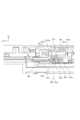
図8(a)(b)は、カテーテルユニット100とベースユニット200の連結を説明する図である。図8(a)は、カテーテルユニット100とベースユニット200を、回転軸400rに沿って切断した断面図である。図8(b)は、ベースユニット200を、連結部21cの部分で、回転軸400rに直交する方向に切断した断面図である。図9は、カテーテルユニット100に設けられた操作部400と、ベースユニット200に設けられたジョイント28及び内歯ギア29と、を示す分解斜視図である。図10、図11、図12、図13、図14(a)(b)及び図15は、連結部21cによる駆動ワイヤWの固定について説明する図である。 8(a) and 8(b) are diagrams for explaining the connection between thecatheter unit 100 and thebase unit 200. FIG. FIG. 8(a) is a cross-sectional view of thecatheter unit 100 and thebase unit 200 taken along therotation axis 400r. FIG. 8(b) is a cross-sectional view of thebase unit 200 cut at the connectingportion 21c in a direction orthogonal to therotating shaft 400r. FIG. 9 is an exploded perspective view showing the operatingportion 400 provided on thecatheter unit 100, and the joint 28 andinternal gear 29 provided on thebase unit 200. FIG. 10, 11, 12, 13, 14(a), 14(b), and 15 are diagrams illustrating fixing of the drive wire W by the connectingportion 21c.

図8(a)及び図9に示すように、ベースユニット200は、ジョイント(中間部材、第2伝達部材)28と、ジョイント28を介して操作部400と連動する移動ギア(連動ギア、伝達部材、第1伝達部材)としての内歯ギア29と、を有する。ジョイント28は、複数(本実施形態では8つ)の伝達部28cを有し、内歯ギア29は、複数(本実施形態では8つ)の被伝達部29cを有する。複数の伝達部28cは、複数の被伝達部29cに係合しており、ジョイント28が回転した場合、ジョイント28に連動して内歯ギア29も回転するように構成されている。 As shown in FIGS. 8A and 9 , thebase unit 200 includes a joint (intermediate member, second transmission member) 28 and a moving gear (interlocking gear, transmission member) interlocking with theoperation unit 400 via the joint 28 . , and aninternal gear 29 as a first transmission member). The joint 28 has a plurality of (eight in this embodiment) transmittingportions 28c, and theinternal gear 29 has a plurality of (eight in this embodiment) transmittedportions 29c. The plurality of transmittingportions 28c are engaged with the plurality of transmittedportions 29c, and are configured to rotate theinternal gear 29 interlockingly with the joint 28 when the joint 28 rotates.

また、ジョイント28には、180度位相が異なるように配置された1対のジョイント係合部28jが設けられ、操作部400には、1対のジョイント係合部28jに係合する1対の係合部400jが設けられている。カテーテルユニット100がベースユニット200に取り付けられると、1対の係合部400jに1対のジョイント係合部28jが係合する。これにより、操作部400、ジョイント28及び内歯ギア29は、一体となって同方向に回転可能となる。すなわち、カテーテルユニット100がベースユニット200に取り付けられた状態で操作部400が回転されると、操作部400と同方向にジョイント28及び内歯ギア29も回転する。 In addition, the joint 28 is provided with a pair of jointengaging portions 28j arranged so as to be 180 degrees out of phase. Anengaging portion 400j is provided. When thecatheter unit 100 is attached to thebase unit 200, the pair of jointengaging portions 28j are engaged with the pair of engagingportions 400j. As a result, the operatingportion 400, the joint 28, and theinternal gear 29 are integrally rotatable in the same direction. That is, when the operatingportion 400 is rotated while thecatheter unit 100 is attached to thebase unit 200 , the joint 28 and theinternal gear 29 also rotate in the same direction as the operatingportion 400 .

内歯ギア29の内周面には、ギア部としての複数の歯部29gが設けられている。複数の歯部29gは、第1~第9連結部(21c11~21c33)のそれぞれが、第1~第9駆動ワイヤ(W11~W33)のそれぞれを固定する状態と、第1~第9駆動ワイヤ(W11~W33)のそれぞれを解放する状態とを切り替える機能を有する。これら複数の歯部(作用部、切替ギア部)29gのそれぞれは、第1~第9連結部(21c11~21c33)のそれぞれが有する回転体21cpのギア部21cgと係合する。 The inner peripheral surface of theinternal gear 29 is provided with a plurality oftooth portions 29g as gear portions. The plurality oftooth portions 29g are arranged such that the first to ninth connecting portions (21c11 to 21c33) respectively fix the first to ninth drive wires (W11 to W33), and the first to ninth drive wires (W11 to W33) has a function of switching between a state in which each of them is released. Each of the plurality of tooth portions (action portion, switching gear portion) 29g engages with the gear portion 21cg of the rotor 21cp of each of the first to ninth connecting portions (21c11 to 21c33).

具体的には、内歯ギア29は、図8(b)に示すように、第1歯部29g11、第2歯部29g12、第3歯部29g13、第4歯部29g21、第5歯部29g22、第6歯部29g23、第7歯部29g31、第8歯部29g32、第9歯部29g33を備える。第1~第9歯部(29g11~29g33)のそれぞれは、互いに隙間を空けて形成されている。 Specifically, as shown in FIG. 8B, theinternal gear 29 includes a first tooth portion 29g11, a second tooth portion 29g12, a third tooth portion 29g13, a fourth tooth portion 29g21, and a fifth tooth portion 29g22. , a sixth tooth 29g23, a seventh tooth 29g31, an eighth tooth 29g32 and a ninth tooth 29g33. Each of the first to ninth tooth portions (29g11 to 29g33) is formed with a gap therebetween.

第1歯部29g11は、第1連結部21c11のギア部21cgと噛み合う。第2歯部29g12は、第2連結部21c12のギア部21cgと噛み合う。第3歯部29g13は、第3連結部21c13のギア部21cgと噛み合う。第4歯部29g21は、第4連結部21c21のギア部21cgと噛み合う。第5歯部29g22は、第5連結部21c22のギア部21cgと噛み合う。第6歯部29g23は、第6連結部21c23のギア部21cgと噛み合う。第7歯部29g31は、第7連結部21c31のギア部21cgと噛み合う。第8歯部29g32は、第8連結部21c32のギア部21cgと噛み合う。第9歯部29g33は、第9連結部21c33のギア部21cgと噛み合う。 The first tooth portion 29g11 meshes with the gear portion 21cg of the first connecting portion 21c11. The second tooth portion 29g12 meshes with the gear portion 21cg of the second connecting portion 21c12. The third tooth portion 29g13 meshes with the gear portion 21cg of the third connecting portion 21c13. The fourth tooth portion 29g21 meshes with the gear portion 21cg of the fourth connecting portion 21c21. The fifth tooth portion 29g22 meshes with the gear portion 21cg of the fifth connecting portion 21c22. The sixth tooth portion 29g23 meshes with the gear portion 21cg of the sixth connecting portion 21c23. The seventh tooth portion 29g31 meshes with the gear portion 21cg of the seventh connecting portion 21c31. The eighth tooth portion 29g32 meshes with the gear portion 21cg of the eighth connecting portion 21c32. The ninth tooth portion 29g33 meshes with the gear portion 21cg of the ninth connecting portion 21c33.

第1~第9歯部(29g11~29g33)のうち、任意の一つを、歯部29gと呼ぶことができる。本実施形態において、第1~第9歯部(29g11~29g33)のそれぞれは、同一構成である。また、第1~第9駆動ワイヤ(W11~W33)のそれぞれと第1~第9連結部(21c11~21c33)のそれぞれが連結される構成は、同一である。また、第1~第9連結部(21c11~21c33)のそれぞれと第1~第9歯部(29g11~29g33)のそれぞれが接続される構成は、同一である。従って、以下の説明では、一つの駆動ワイヤW、一つの連結部21c、一つの歯部29gを用いて、これらが接続される構成について説明する。 Any one of the first to ninth teeth (29g11 to 29g33) can be called atooth 29g. In this embodiment, each of the first to ninth tooth portions (29g11 to 29g33) has the same configuration. In addition, the structure in which each of the first to ninth drive wires (W11 to W33) and each of the first to ninth connecting portions (21c11 to 21c33) are connected is the same. Also, the configuration in which each of the first to ninth connecting portions (21c11 to 21c33) and each of the first to ninth tooth portions (29g11 to 29g33) are connected is the same. Therefore, in the following description, one driving wire W, one connectingportion 21c, and onetooth portion 29g are used to connect them.

第1~第9連結部(21c11~21c33)のそれぞれにおいて、ギア部21cgが内歯ギア29の歯部29gによって移動されることにより、回転体21cpが回転する。これにより、回転体21cpのカム21ccが、被保持部Waを交差方向としての-Y方向に押圧可能な図15に示す押圧位置と、押圧位置よりも被保持部Waから離間した図10に示す離間位置と、の間で移動する。 In each of the first to ninth connecting portions (21c11 to 21c33), the gear portion 21cg is moved by thetooth portion 29g of theinternal gear 29, thereby rotating the rotor 21cp. As a result, the cam 21cc of the rotating body 21cp can press the held portion Wa in the -Y direction as the intersecting direction, as shown in FIG. Move between the spaced position and.

上述したように、操作部400を回転させることにより、操作部400と一体に内歯ギア29が回転する。内歯ギア29が回転することにより、第1~第9連結部(21c11~21c33)それぞれが動作する。つまり、一つの操作部400を回転させる動作によって、第1~第9連結部(21c11~21c33)を動作させることができる。 As described above, theinternal gear 29 rotates integrally with the operatingportion 400 by rotating the operatingportion 400 . Rotation of theinternal gear 29 causes the first to ninth connecting portions (21c11 to 21c33) to operate. That is, the first to ninth connecting portions (21c11 to 21c33) can be operated by rotating oneoperating portion 400. FIG.

操作部400は、カテーテルユニット100がベースユニット200に装着された状態で、固定位置(ロック位置)と、取り外し位置とに移動することができる。また、後述するように、操作部400は、カテーテルユニット100がベースユニット200に装着された状態で、解除位置に移動することができる。操作部400の周方向について、解除位置は、固定位置と取り外し位置の間に位置される。操作部400が取り外し位置に位置された状態で、ベースユニット200にカテーテルユニット100が取り付けられる。 With thecatheter unit 100 attached to thebase unit 200, theoperating section 400 can move between a fixed position (locked position) and a removed position. Further, as will be described later, theoperating section 400 can move to the release position while thecatheter unit 100 is attached to thebase unit 200 . With respect to the circumferential direction of the operatingportion 400, the release position is positioned between the fixed position and the removal position. Thecatheter unit 100 is attached to thebase unit 200 with the operatingportion 400 positioned at the removal position.

カテーテルユニット100をベースユニット200に取り付けた状態では、駆動ワイヤWの連結部21cへの固定(ロック)が解除された状態である。この状態を、連結部21cの解除状態と呼ぶ。なお、駆動ワイヤWが連結部21cへ固定(ロック)された状態を、連結部21cのロック状態と呼び、駆動ワイヤWの連結部21cへの固定が解除された状態を連結部21cの状態を解除状態と呼ぶ。 When thecatheter unit 100 is attached to thebase unit 200, the driving wire W is unlocked from the connectingportion 21c. This state is called a released state of the connectingportion 21c. The state in which the drive wire W is fixed (locked) to theconnection portion 21c is called the locked state of theconnection portion 21c, and the state in which the drive wire W is released from theconnection portion 21c is called the state of theconnection portion 21c. called the released state.

図10、図11、図12、図13、図14、図15を用いて、駆動ワイヤWを連結部21cへ固定する際の動作について説明する。カテーテルユニット100をベースユニット200に取り付けた後、かつ操作部400を操作する前の状態では、カテーテルユニット100は、ベースユニット200から取り外すことができる。以下、カテーテルユニット100がベースユニット200から取り外すことが可能な状態を、取り外し可能状態と呼ぶ。 10, 11, 12, 13, 14, and 15, the operation of fixing the drive wire W to the connectingportion 21c will be described. Thecatheter unit 100 can be removed from thebase unit 200 after thecatheter unit 100 is attached to thebase unit 200 and before theoperation section 400 is operated. A state in which thecatheter unit 100 can be removed from thebase unit 200 is hereinafter referred to as a detachable state.

図10は、取り外し可能状態における内歯ギア29と連結部21cの状態を示す図である。すなわち、図10は、操作部400が取り外し位置にある状態における、内歯ギア29と連結部21cを示す図である。 FIG. 10 is a diagram showing the state of theinternal gear 29 and the connectingportion 21c in the detachable state. That is, FIG. 10 is a diagram showing theinternal gear 29 and the connectingportion 21c when the operatingportion 400 is at the removal position.

連結ベース21cbは、図10に示すように、カム保持部21ceと、駆動ワイヤWの被保持部Waを支持する複数(本実施形態では各ワイヤにつき3つ)のロッド支持面21cdと、当接部としての挟持面21chと、を有する。回転体21cpに設けられたカム21ccは、保持面21ccaと、押圧面21ccbと、を有する。保持面21ccaは、カム保持部21ceの形状に沿って、窪んで形成されている。 As shown in FIG. 10, the connecting base 21cb is in contact with a cam holding portion 21ce and a plurality of (three for each wire in this embodiment) rod supporting surfaces 21cd that support the held portion Wa of the driving wire W. and a holding surface 21ch as a portion. A cam 21cc provided on the rotating body 21cp has a holding surface 21cca and a pressing surface 21ccb. The holding surface 21cca is recessed along the shape of the cam holding portion 21ce.

図10に示すように、取り外し可能状態(操作部400が取り外し位置にある状態)では、回転体21cpは、保持面21ccaが連結ベース21cbのカム保持部21ceに係合した位置で保持されている。言い換えれば、第2規制部としてのカム保持部21ceは、回転体21cpの反時計回り方向CCWの回転を規制している。また、ギア部21cgは、歯部29gと係合可能な第1の歯としての歯Zb1と、歯部29gに係合可能であり、歯Zb1よりも第1回転方向としての時計回り方向CWにおける上流に配置される第2の歯としての歯Zb2と、を有している。内歯ギア29の歯部29gとギア部21cgの歯Zb1は、互いの間にクリアランスLaが生じた状態で、停止している。なお、内歯ギア29の歯部29gは、回転体21cpの回転軸21cpcと平行な軸としての回転軸400r(図8(a)参照)を中心に回転可能である。 As shown in FIG. 10, in the detachable state (state in which theoperation unit 400 is at the detachment position), the rotating body 21cp is held at a position where the holding surface 21cca is engaged with the cam holding portion 21ce of the connecting base 21cb. . In other words, the cam holding portion 21ce as the second restricting portion restricts the rotation of the rotor 21cp in the counterclockwise direction CCW. In addition, the gear portion 21cg has a tooth Zb1 as a first tooth that can be engaged with thetooth portion 29g, and a tooth Zb1 that can be engaged with thetooth portion 29g, and is rotated in the clockwise direction CW as the first rotation direction from the tooth Zb1. and a tooth Zb2 as a second tooth arranged upstream. Thetooth portion 29g of theinternal gear 29 and the tooth Zb1 of the gear portion 21cg are stopped with a clearance La between them. Theteeth 29g of theinternal gear 29 are rotatable around arotation axis 400r (see FIG. 8A) parallel to the rotation axis 21cpc of the rotor 21cp.

操作部400の回転方向において、操作部400が取り外し位置から解除位置及び固定位置に向かう方向をロック方向(固定方向)と呼び、操作部400が固定位置から解除位置及び取り外し位置に向かう方向を解除方向と呼ぶ。操作部400は、解除位置から解除方向に回転して、取り外し位置に移動する。操作部400は、解除位置からロック方向に回転して、固定位置に移動する。 Regarding the rotation direction of theoperation unit 400, the direction in which theoperation unit 400 moves from the removal position to the release position and the fixing position is called the lock direction (fixing direction), and the direction in which theoperation unit 400 moves from the fixing position to the release position and the removal position is called the release direction. called direction. Theoperation part 400 rotates in the release direction from the release position and moves to the removal position. The operatingportion 400 rotates in the locking direction from the unlocked position and moves to the fixed position.

カテーテルユニット100をベースユニット200に取り付け、操作部400が取り外し位置にある状態では、連結部21cは解除状態であり、連結部21cによる駆動ワイヤWの固定が解除された状態である。また、回転体21cpのカム21ccは、被保持部Waから離間した離間位置に位置している。このとき、被保持部Waは連結ベース21cbに設けられたロッド支持面21cdによって支持されているが、-Y方向のみロッド支持面21cdが存在しない状態になっている。すなわち、被保持部Waと挟持面21chとの間には隙間が空いている。これにより、被保持部Waは、-Y方向にのみ移動可能に支持されている。 When thecatheter unit 100 is attached to thebase unit 200 and theoperation part 400 is at the removal position, the connectingpart 21c is in a released state, and the fixing of the driving wire W by the connectingpart 21c is released. Further, the cam 21cc of the rotating body 21cp is positioned at a separated position away from the held portion Wa. At this time, the held portion Wa is supported by the rod support surface 21cd provided on the connecting base 21cb, but the rod support surface 21cd does not exist only in the -Y direction. That is, there is a gap between the held portion Wa and the holding surface 21ch. Thereby, the held portion Wa is supported so as to be movable only in the -Y direction.

連結部21cが解除状態にあるとき、カム21ccは、被保持部Waと所定のクリアランスをもって離間している。すなわち、被保持部Waの固定は解除された状態である。連結部21cが解除状態にあるとき、ベースユニット200に対してカテーテルユニット100を取り外し方向Ddに動かした場合には、連結ベース21cbから被保持部Waを引き抜くことができる。 When the connectingportion 21c is in the released state, the cam 21cc is separated from the held portion Wa with a predetermined clearance. That is, the fixation of the held portion Wa is released. When thecatheter unit 100 is moved in the detachment direction Dd with respect to thebase unit 200 when the connectingportion 21c is in the released state, the held portion Wa can be pulled out from the connecting base 21cb.

図11は、操作部400を取り外し位置からロック方向に回転したときの内歯ギア29と連結部21cの状態を示す図である。図11は、操作部400が解除位置にある状態における内歯ギア29と連結部21cの状態を示す図である。 FIG. 11 is a diagram showing the state of theinternal gear 29 and the connectingportion 21c when the operatingportion 400 is rotated in the lock direction from the detached position. FIG. 11 is a diagram showing the state of theinternal gear 29 and the connectingportion 21c when the operatingportion 400 is at the release position.

操作部400が取り外し位置にある状態(図10参照)で、操作部400をロック方向に回転させると、内歯ギア29が時計回り方向に回転する。そして、操作部400は、解除位置に位置する。 When the operatingportion 400 is rotated in the lock direction while the operatingportion 400 is in the removal position (see FIG. 10), theinternal gear 29 rotates clockwise. Then, theoperation unit 400 is positioned at the release position.

なお、操作部400を回転させた場合であっても、キーシャフト15とキー受け部22が係合しているため、カテーテルユニット100の全体(操作部400を除く)は、ベースユニット200に対して回転することが規制されている。つまり、操作部400は、カテーテルユニット100の全体(操作部400を除く)とベースユニット200が停止した状態で、それらに対して回転可能である。 Note that even when the operatingportion 400 is rotated, the entire catheter unit 100 (excluding the operating portion 400) remains in contact with thebase unit 200 because thekey shaft 15 and thekey receiving portion 22 are engaged. rotation is restricted. That is, the operatingportion 400 can rotate with respect to the entire catheter unit 100 (excluding the operating portion 400) and thebase unit 200 in a stopped state.

内歯ギア29が時計回り方向に回転することで、内歯ギア29の歯部29gとギア部21cgの歯Zb1の間のクリアランスは、クリアランスLaからクリアランスLbに減少する。 As theinternal gear 29 rotates clockwise, the clearance between thetooth portion 29g of theinternal gear 29 and the tooth Zb1 of the gear portion 21cg is reduced from the clearance La to the clearance Lb.

ギア部21cgの歯Zb2は、内歯ギア29の歯部29gの歯先円(点線)との間にクリアランスLzを空けた位置に配置されている。そのため、内歯ギア29は歯Zb2に干渉することなく回転可能である。一方、連結部21cは、図10に示された状態と同じ状態(解除状態)に保たれている。 The tooth Zb2 of the gear portion 21cg is arranged at a position with a clearance Lz between it and the addendum circle (dotted line) of thetooth portion 29g of theinternal gear 29 . Therefore, theinternal gear 29 can rotate without interfering with the teeth Zb2. On the other hand, the connectingportion 21c is kept in the same state (released state) as shown in FIG.

図11に示した状態から、操作部400をロック方向にさらに回転させると、内歯ギア29が時計回り方向にさらに回転する。そのときの内歯ギア29と連結部21cの状態を図12に示す。 When the operatingportion 400 is further rotated in the locking direction from the state shown in FIG. 11, theinternal gear 29 is further rotated clockwise. FIG. 12 shows the state of theinternal gear 29 and the connectingportion 21c at that time.

図12は、操作部400を解除位置からロック方向に回転したときの内歯ギア29と連結部21cの状態を示す図である。図12に示すように、操作部400を解除位置からロック方向に回転すると、内歯ギア29の歯部29gとギア部21cgの歯Zb1が接触する。一方、連結部21cは、図10、図11に示された状態と同じ状態であり、解除状態に保たれている。 FIG. 12 shows the state of theinternal gear 29 and the connectingportion 21c when the operatingportion 400 is rotated from the unlocked position in the locking direction. As shown in FIG. 12, when the operatingportion 400 is rotated from the unlocked position in the locking direction, thetooth portion 29g of theinternal gear 29 and the tooth Zb1 of the gear portion 21cg come into contact with each other. On the other hand, the connectingportion 21c is in the same state as shown in FIGS. 10 and 11, and is kept in the released state.

図12に示した状態から、操作部400をロック方向にさらに回転させると、内歯ギア29が時計回り方向にさらに回転する。そのときの内歯ギア29と連結部21cの状態を図13に示す。図13は、操作部400を図12の状態からロック方向に回転したときの内歯ギア29と連結部21cの状態を示す図である。図13に示すように、図12の状態から操作部400をロック方向にさらに回転させると、内歯ギア29が時計回り方向にさらに回転する。 When the operatingportion 400 is further rotated in the locking direction from the state shown in FIG. 12, theinternal gear 29 is further rotated clockwise. FIG. 13 shows the state of theinternal gear 29 and the connectingportion 21c at that time. FIG. 13 shows the state of theinternal gear 29 and thecoupling portion 21c when the operatingportion 400 is rotated in the lock direction from the state shown in FIG. As shown in FIG. 13, when the operatingportion 400 is further rotated in the locking direction from the state of FIG. 12, theinternal gear 29 is further rotated clockwise.

内歯ギア29が図12の状態から図13の状態に移動することで、内歯ギア29は、ギア部21cgを時計回り方向CWに回転させる。ギア部21cgが回転すると、保持面21ccaとカム保持部21ceの係合が解除され、カム21ccが被保持部Waに接触する。そのため、被保持部Waは、カム21ccから力を受け始める。 As theinternal gear 29 moves from the state shown in FIG. 12 to the state shown in FIG. 13, theinternal gear 29 rotates the gear portion 21cg in the clockwise direction CW. When the gear portion 21cg rotates, the engagement between the holding surface 21cca and the cam holding portion 21ce is released, and the cam 21cc contacts the held portion Wa. Therefore, the held portion Wa begins to receive force from the cam 21cc.

図14(a)は、操作部400を図13の状態からロック方向に回転したときの内歯ギア29と連結部21cの状態を示す図である。図14(a)に示すように、図13の状態から操作部400をロック方向にさらに回転させると、内歯ギア29が時計回り方向にさらに回転する。内歯ギア29が図13の状態から図14(a)の状態に移動することで、内歯ギア29はギア部21cgを時計回り方向CWに回転させる。ギア部21cgが回転するときの押圧面21ccbの回転軌跡は、図13の状態における被保持部Waの位置(図14(a)に点線で示す)とオーバーラップしている。よって、ギア部21cgが回転すると、押圧面21ccbは、被保持部Waと干渉しながら回転する。このとき、被保持部Waは、連結ベース21cbに設けられた案内部としての複数のロッド支持面21cdにより、-Y方向に案内されるため、押圧面21ccbに押されて-Y方向に移動する。これにより、被保持部Waは、挟持面21chに突き当たって当接する。 FIG. 14(a) is a diagram showing the state of theinternal gear 29 and the connectingportion 21c when the operatingportion 400 is rotated in the locking direction from the state of FIG. As shown in FIG. 14(a), when the operatingportion 400 is further rotated in the locking direction from the state of FIG. 13, theinternal gear 29 is further rotated clockwise. As theinternal gear 29 moves from the state shown in FIG. 13 to the state shown in FIG. 14A, theinternal gear 29 rotates the gear portion 21cg in the clockwise direction CW. The locus of rotation of the pressing surface 21ccb when the gear portion 21cg rotates overlaps the position of the held portion Wa in the state of FIG. 13 (indicated by the dotted line in FIG. 14(a)). Therefore, when the gear portion 21cg rotates, the pressing surface 21ccb rotates while interfering with the held portion Wa. At this time, since the held portion Wa is guided in the -Y direction by a plurality of rod support surfaces 21cd as guide portions provided on the connecting base 21cb, it is pushed by the pressing surface 21ccb and moves in the -Y direction. . As a result, the held portion Wa hits and abuts against the holding surface 21ch.

図14(b)は、図14(a)の内歯ギア29と連結部21cの状態を示す断面図である。図14(b)に示すように、被保持部Waが-Y方向に移動するとき、ワイヤガイド17に支持された可撓性部材であるワイヤ体Wbは弾性変形する。具体的には、被保持部Waは、Z方向においてワイヤガイド17よりも連結部21cに近い位置に位置しており、ワイヤ体Wbの自由端に位置している。そして、ワイヤ体Wbは、被保持部Waがカム21ccによって押圧されることで、ワイヤガイド17のZ方向における連結部21cに近い側の端部としてのワイヤ体支持端Wbaを支点に、凹部Wcと凸部21ciとが互いに近づくように-Y方向に撓む。また、カム21ccによって押圧されることで被保持部Waが-Y方向に移動したとき、被保持部Waに設けられた凹部Wcと挟持面21chに設けられた凸部21ciとが係合する。これにより被保持部Waは、連結ベース21cbに固定される。 FIG. 14(b) is a sectional view showing the state of theinternal gear 29 and the connectingportion 21c of FIG. 14(a). As shown in FIG. 14(b), when the held portion Wa moves in the -Y direction, the wire body Wb, which is a flexible member supported by thewire guide 17, is elastically deformed. Specifically, the held portion Wa is positioned closer to the connectingportion 21c than thewire guide 17 in the Z direction, and is positioned at the free end of the wire body Wb. When the held portion Wa is pressed by the cam 21cc, the wire body Wb is pushed around the wire body support end Wba as the end of thewire guide 17 on the side closer to the connectingportion 21c in the Z direction, and the recess Wc is formed. and the convex portion 21ci are bent in the -Y direction so that they approach each other. Further, when the held portion Wa is moved in the -Y direction by being pressed by the cam 21cc, the concave portion Wc provided on the held portion Wa and the convex portion 21ci provided on the holding surface 21ch are engaged. As a result, the held portion Wa is fixed to the connecting base 21cb.

なお、被保持部Waに設けられた凹部Wcは、被保持部Waの外周面の全周に形成されており、着脱方向DEに交差する方向に窪んでいる。凸部21ciは、着脱方向DEに交差する方向に突出している。このため、被保持部Waが回転方向においてどのような位相であっても、凹部Wcは凸部21ciに係合することができる。そして、凹部Wc及び凸部21ciが係合することにより、被保持部Waが連結部21cに対して着脱方向DEに相対的に移動することが規制される。すなわち、連結部21cと被保持部Waは、ワイヤ駆動部300からの駆動力によって図6(a)に示すDc方向に一体的に移動可能となる。 The recessed portion Wc provided in the held portion Wa is formed along the entire outer peripheral surface of the held portion Wa, and is recessed in a direction intersecting the attachment/detachment direction DE. The convex portion 21ci protrudes in a direction crossing the attachment/detachment direction DE. Therefore, the concave portion Wc can be engaged with the convex portion 21ci regardless of the phase of the held portion Wa in the rotational direction. The engagement between the concave portion Wc and the convex portion 21ci restricts the relative movement of the held portion Wa in the attachment/detachment direction DE with respect to the connectingportion 21c. In other words, the connectingportion 21c and the held portion Wa are integrally movable in the Dc direction shown in FIG. 6A by the driving force from thewire driving portion 300.

また、カム21ccは、被保持部Waが挟持面21chに突き当たった状態で被保持部Waを押圧する際に、弾性変形可能に構成されている。カム21ccの弾性力によって、被保持部Waは、カム21ccと挟持面21chによって挟持され、連結ベース21cbに強く固定される。 Further, the cam 21cc is configured to be elastically deformable when pressing the held portion Wa while the held portion Wa abuts against the holding surface 21ch. Due to the elastic force of the cam 21cc, the held portion Wa is clamped between the cam 21cc and the clamping surface 21ch and strongly fixed to the connecting base 21cb.

内歯ギア29の歯部29gがギア部21cgの歯Zb1から離れたとき、内歯ギア29からギア部21cgへの駆動力の伝達が終了する。このとき、カム21ccは弾性変形しているため、固定されている被保持部Waから反力Fを受ける状態になる。反力Fは、回転体21cpの回転軸21cpcからずれた方向に作用しており、回転体21cpは、反力Fによって図14(a)において時計回り方向CWに付勢される。このとき、回転体21cpは、時計回り方向に回る内歯ギア29によって回転させられる方向と、同じ方向に向けて回転する。 When thetooth portion 29g of theinternal gear 29 is separated from the tooth Zb1 of the gear portion 21cg, transmission of driving force from theinternal gear 29 to the gear portion 21cg is terminated. At this time, since the cam 21cc is elastically deformed, it is in a state of receiving a reaction force F from the fixed held portion Wa. The reaction force F acts in a direction deviated from the rotation axis 21cpc of the rotating body 21cp, and the rotating body 21cp is urged in the clockwise direction CW in FIG. At this time, the rotor 21cp rotates in the same direction as the direction rotated by theinternal gear 29 rotating clockwise.

図15は、操作部400が図14の(a)状態からロック方向に回転して固定位置に位置したときの、内歯ギア29と連結部21cの状態を示す図である。図15に示すように、図14(a)に示す状態から、カム21ccが反力Fを受けることで、回転体21cpはさらに時計回り方向CWに回転する。 FIG. 15 is a diagram showing the state of theinternal gear 29 and the connectingportion 21c when theoperation portion 400 rotates in the locking direction from the state (a) of FIG. 14 and is positioned at the fixed position. As shown in FIG. 15, the cam 21cc receives the reaction force F from the state shown in FIG. 14(a), so that the rotor 21cp further rotates in the clockwise direction CW.

そして、図15に示すように、回転体21cpは、歯Zb1に設けられた突き当て面Zb1aが連結ベース21cbに設けられた被突き当て面21cfに突き当たることで回転停止する。すなわち、第1規制部としての被突き当て面21cfは、反力Fによって時計回り方向CWに付勢された回転体21cpの時計回り方向CWの回転を規制する。このとき、連結部21cはロック状態にある。連結部21cがロック状態にあるとき、回転体21cpのカム21ccは、押圧位置に位置し、押圧面21ccbが被保持部Waを連結ベース21cbの挟持面21chに向けて押圧している。被保持部Waが押圧面21ccbによって押圧された状態では、図14(b)に示すように、凹部Wcと凸部21ciが係合するため、被保持部Waを安定して連結部21cに対して固定することができる。連結部21cがロック状態にあるとき、連結ベース21cbから被保持部Waを引き抜くことが制限される。なお、内歯ギア29の歯部29gとギア部21cgの歯Zb2は、互いの間にクリアランスLcが生じる位置で停止している。 Then, as shown in FIG. 15, the rotating body 21cp stops rotating when the abutment surface Zb1a provided on the tooth Zb1 abuts against the abutted surface 21cf provided on the connecting base 21cb. That is, the abutting surface 21cf as the first restricting portion restricts the rotation in the clockwise direction CW of the rotor 21cp that is biased clockwise by the reaction force F. As shown in FIG. At this time, the connectingportion 21c is in a locked state. When the connectingportion 21c is in the locked state, the cam 21cc of the rotating body 21cp is positioned at the pressing position, and the pressing surface 21ccb presses the held portion Wa toward the clamping surface 21ch of the connecting base 21cb. In a state where the held portion Wa is pressed by the pressing surface 21ccb, as shown in FIG. can be fixed. When the connectingportion 21c is in the locked state, the pulling out of the held portion Wa from the connecting base 21cb is restricted. Thetooth portion 29g of theinternal gear 29 and the tooth Zb2 of the gear portion 21cg are stopped at a position where a clearance Lc is generated between them.

駆動ワイヤWと連結部21cの固定を解除する際には、固定位置に位置する操作部400を、解除方向に回転させる。このとき、内歯ギア29は、図15に示す状態から、反時計回り方向に回転する。内歯ギア29が反時計回り方向に回転すると、ギア部21cgの歯Zb2に、内歯ギア29の歯部29gが当接し、回転体21cpが、時計回り方向とは反対の、第2回転方向としての反時計回り方向CCWに回転させられる。 When fixing the drive wire W and the connectingportion 21c is released, the operatingportion 400 positioned at the fixed position is rotated in the releasing direction. At this time, theinternal gear 29 rotates counterclockwise from the state shown in FIG. When theinternal gear 29 rotates counterclockwise, theteeth 29g of theinternal gear 29 come into contact with the teeth Zb2 of the gear portion 21cg, and the rotor 21cp rotates in the second direction of rotation opposite to the clockwise direction. is rotated in the counterclockwise direction CCW as .

内歯ギア29をさらに反時計回り方向に回転させることで、連結部21cによる駆動ワイヤWの固定が解除される。このときの内歯ギア29と回転体21cpの動作は、上述した動作と逆の動作である。つまり、上述した駆動ワイヤWを連結部21cによって固定する際の動作とは逆の動作により、連結部21cによる駆動ワイヤWの固定が解除される。 By further rotating theinternal gear 29 in the counterclockwise direction, the fixation of the drive wire W by the connectingportion 21c is released. The operations of theinternal gear 29 and the rotor 21cp at this time are operations opposite to those described above. That is, the fixation of the drive wire W by theconnection portion 21c is released by the operation opposite to the operation when the drive wire W is fixed by theconnection portion 21c described above.

上記の動作は、第1~第9連結部(21c11~21c33)のそれぞれで行われる。すなわち、操作部400が取り外し位置から固定位置に移動する過程で、操作部400の移動(回転)により、第1~第9連結部(21c11~21c33)が解除状態からロック状態になる。操作部400が固定位置から取り外し位置に移動する過程で、操作部400の移動(回転)により、第1~第9連結部(21c11~21c33)がロック状態から解除状態になる。つまり、使用者は、一つの操作部400を操作することによって、複数の連結部の解除状態、ロック状態を切り替えることができる。 The above operations are performed in each of the first to ninth connecting portions (21c11 to 21c33). That is, in the process of moving the operatingportion 400 from the detached position to the fixed position, the movement (rotation) of the operatingportion 400 causes the first to ninth connecting portions (21c11 to 21c33) to change from the released state to the locked state. During the process of moving the operatingportion 400 from the fixed position to the removing position, the movement (rotation) of the operatingportion 400 causes the first to ninth connecting portions (21c11 to 21c33) to change from the locked state to the unlocked state. In other words, the user can switch between the released state and the locked state of the plurality of connecting portions by operating oneoperating portion 400 .

つまり、複数の連結部のそれぞれに、解除状態、ロック状態を切り替えるための操作部を設け、使用者がそれを操作する必要がない。したがって、使用者は容易にカテーテルユニット100をベースユニット200に着脱することができる。さらに、医療装置1を簡略化することができる。 In other words, it is not necessary for the user to operate an operating section for switching between the unlocked state and the locked state for each of the plurality of connecting sections. Therefore, the user can easily attach/detach thecatheter unit 100 to/from thebase unit 200 . Furthermore, themedical device 1 can be simplified.

第1~第9駆動ワイヤ(W11~W33)のそれぞれが第1~第9連結部(21c11~21c33)のそれぞれによって固定された状態を第1状態と呼ぶ。第1~第9連結部(21c11~21c33)のそれぞれによる第1~第9駆動ワイヤ(W11~W33)のそれぞれに対する固定が解除された状態を第2状態と呼ぶ。 A state in which the first to ninth drive wires (W11 to W33) are respectively fixed by the first to ninth connecting portions (21c11 to 21c33) is called a first state. A state in which the first to ninth connecting portions (21c11 to 21c33) are released from the first to ninth driving wires (W11 to W33) is called a second state.

操作部400の移動に連動して、第1状態と第2状態とが切り替えられる。つまり、取り外し位置と固定位置との間における操作部400の移動に連動して、第1状態と第2状態とが切り替えられる。 The first state and the second state are switched in conjunction with the movement of theoperation unit 400 . That is, the first state and the second state are switched in conjunction with the movement of theoperation unit 400 between the removal position and the fixed position.

内歯ギア29は、操作部400と連動するように構成されている。本実施形態では、ジョイント28は、操作部400と内歯ギア29を連動させるための伝達部材として機能する。内歯ギア29及びジョイント28は、操作部400の移動に連動して第1状態と第2状態とが切り替わるように、操作部400と連動する連動部としての機能を有する。 Theinternal gear 29 is configured to interlock with the operatingportion 400 . In this embodiment, the joint 28 functions as a transmission member for interlocking the operatingportion 400 and theinternal gear 29 . Theinternal gear 29 and the joint 28 have a function as an interlocking part that interlocks with theoperation part 400 so that the first state and the second state are switched in conjunction with the movement of theoperation part 400 .

具体的には、内歯ギア29及びジョイント28は、カテーテルユニット100がベースユニット200に取り付けられた状態で、操作部400の移動と連動して、回転体21cpの一部(カム21cc)を、被保持部Waに対して移動させる。カム21ccが移動することで、連結部21cのロック状態と、解除状態とが切り替えられる。なお、ジョイント28を省き、内歯ギア29が操作部400から直接移動される構成としてもよい。その場合、内歯ギア29が連動部としての機能を有する。 Specifically, in a state where thecatheter unit 100 is attached to thebase unit 200, theinternal gear 29 and the joint 28 interlock with the movement of theoperation part 400 to move a part of the rotating body 21cp (the cam 21cc) to It is moved with respect to the held portion Wa. By moving the cam 21cc, theconnection portion 21c is switched between the locked state and the unlocked state. A configuration in which the joint 28 is omitted and theinternal gear 29 is directly moved from the operatingportion 400 may be employed. In that case, theinternal gear 29 functions as an interlocking portion.

<操作部の移動>
次に、図16(a)~(c)、図17(a)~(c)、図18(a)~(c)を用いて、操作部400の移動について説明する。
<Movement of operation part>
Next, movement of theoperation unit 400 will be described with reference to FIGS. 16(a) to (c), FIGS. 17(a) to (c) and FIGS. 18(a) to (c).

本実施形態において、操作部400は、カテーテルユニット100がベースユニット200に装着された状態で、取り外し位置と、解除位置と、固定位置との間を移動可能に構成されている。解除位置は、取り外し位置と固定位置の間に位置する。 In the present embodiment, theoperating section 400 is configured to be movable between a removal position, a release position, and a fixed position while thecatheter unit 100 is attached to thebase unit 200 . The release position is located between the removal position and the locking position.

本実施形態では、操作部400が解除位置と固定位置との間における操作部400の移動に連動して、第1状態と第2状態とが切り替えられる。 In this embodiment, theoperation unit 400 is switched between the first state and the second state in conjunction with the movement of theoperation unit 400 between the release position and the fixed position.

本実施形態において、操作部400は、着脱方向DEと異なる方向に移動することで、取り外し位置と固定位置との間を移動可能である。操作部400は、着脱方向DEに交差する方向(好ましくは直交する方向)に移動して、取り外し位置と固定位置との間を移動する。本実施形態では、操作部400は着脱方向DEに延びる回転軸400rの周りに回転して、取り外し位置と固定位置との間を移動する。したがって、使用者が操作部400を操作する際の操作性が良好である。 In this embodiment, theoperation unit 400 can move between the removal position and the fixed position by moving in a direction different from the attachment/detachment direction DE. Theoperation part 400 moves in a direction intersecting (preferably orthogonal to) the attachment/detachment direction DE to move between the removal position and the fixing position. In this embodiment, theoperation unit 400 rotates around arotation shaft 400r extending in the attachment/detachment direction DE to move between the removal position and the fixed position. Therefore, the operability when the user operates theoperation unit 400 is excellent.

図16(a)~(c)は、カテーテルユニット100とベースユニット200の説明図である。図16(a)は、カテーテルユニット100の断面図である。図16(b)はボタン41の斜視図である。図16(c)はベースユニット200の斜視図である。 16(a) to (c) are explanatory diagrams of thecatheter unit 100 and thebase unit 200. FIG. FIG. 16(a) is a cross-sectional view of thecatheter unit 100. FIG. FIG. 16(b) is a perspective view of thebutton 41. FIG. FIG. 16(c) is a perspective view of thebase unit 200. FIG.

図17(a)~(c)は、操作部400の動作を説明する図である。図17(a)は、操作部400が取り外し位置にある状態を示す図である。図17(b)は、操作部400が解除位置にある状態を示す図である。図17(c)は、操作部400が固定位置にある状態を示す図である。 17A to 17C are diagrams for explaining the operation of theoperation unit 400. FIG. FIG. 17(a) is a diagram showing a state in which theoperation unit 400 is at the removal position. FIG. 17(b) is a diagram showing a state in which theoperating section 400 is at the release position. FIG. 17(c) is a diagram showing a state in which theoperation unit 400 is in the fixed position.

図18(a)~(c)は、操作部400の動作を説明する断面図である。図18(a)は、操作部400が取り外し位置にある状態を示す断面図である。図18(b)は、操作部400が解除位置にある状態を示す断面図である。図18(c)は、操作部400が固定位置にある状態を示す断面図である。 18A to 18C are cross-sectional views explaining the operation of theoperation unit 400. FIG. FIG. 18(a) is a cross-sectional view showing a state in which theoperation unit 400 is at the removal position. FIG. 18(b) is a cross-sectional view showing a state in which theoperating portion 400 is at the release position. FIG. 18(c) is a cross-sectional view showing a state in which theoperating section 400 is in the fixed position.

操作部400が固定位置にあるとき、連結部21cはロック状態であり、駆動ワイヤWの被保持部Waが対応する連結部21cに固定される(図15参照)。 When the operatingportion 400 is at the fixed position, the connectingportion 21c is in the locked state, and the held portion Wa of the drive wire W is fixed to the corresponding connectingportion 21c (see FIG. 15).

操作部400が解除位置にあるとき、連結部21cは解除状態であり、駆動ワイヤWの被保持部Waと連結部21cのロックが解除されている(図11参照)。この状態では、駆動ワイヤWとワイヤ駆動部300の接続が断たれている。したがって、カテーテル11が外力を受けた際に、ワイヤ駆動部300による抵抗を受けることなく、湾曲部12を自由に屈曲することができる。 When the operatingportion 400 is at the released position, thecoupling portion 21c is in the released state, and the locked portion Wa of the drive wire W and thecoupling portion 21c are unlocked (see FIG. 11). In this state, the connection between the drive wire W and thewire drive section 300 is cut off. Therefore, when thecatheter 11 receives an external force, the bendingportion 12 can be freely bent without receiving resistance from thewire driving portion 300 .

操作部400が取り外し位置にあるとき、カテーテルユニット100をベースユニット200から取り外すことが許容される。また、操作部400が取り外し位置にある状態で、カテーテルユニット100はベースユニット200に取り付けることができる。操作部400が取り外し位置にあるときには、連結部21cは解除状態であり、駆動ワイヤWの被保持部Waと連結部21cのロックが解除されている(図10参照)。 Detachment of thecatheter unit 100 from thebase unit 200 is allowed when theoperation part 400 is in the detachment position. In addition, thecatheter unit 100 can be attached to thebase unit 200 while theoperation section 400 is at the removal position. When the operatingportion 400 is at the removal position, the connectingportion 21c is in the released state, and the locked portion Wa of the drive wire W and the connectingportion 21c are unlocked (see FIG. 10).

図16(a)に示すように、カテーテルユニット100は、操作部400を付勢する操作部付勢バネ43、移動部材としてのボタン41、ボタン41を付勢するボタンバネ42を有する。 As shown in FIG. 16( a ), thecatheter unit 100 has an operatingportion biasing spring 43 that biases the operatingportion 400 , abutton 41 as a moving member, and abutton spring 42 that biases thebutton 41 .

本実施形態において、操作部付勢バネ43は圧縮ばねである。操作部400は、操作部付勢バネ43によって、近位端カバー16に近づく方向Dhに向けて付勢されている。 In this embodiment, the operatingportion biasing spring 43 is a compression spring. The operatingportion 400 is urged in a direction Dh to approach theproximal end cover 16 by an operatingportion urging spring 43 .

本実施形態において、ボタン41、ボタンバネ42は、操作部400に備えられる。操作部400が取り外し位置、解除位置、固定位置に移動するときに、ボタン41、ボタンバネ42は、操作部400と共に移動する。 In this embodiment, thebutton 41 and thebutton spring 42 are provided in theoperating section 400 . Thebutton 41 and thebutton spring 42 move together with theoperation unit 400 when theoperation unit 400 moves to the removal position, release position, and fixing position.

ボタン41は、操作部400の回転軸400rの方向と交差する方向に向けて、操作部400に対して移動可能に構成されている。ボタン41は、ボタンバネ42によって、カテーテルユニット100の外側(回転軸400rから離れる方向)に向けて付勢されている。 Thebutton 41 is configured to be movable with respect to theoperation unit 400 in a direction intersecting with the direction of therotation axis 400 r of theoperation unit 400 . Thebutton 41 is urged by abutton spring 42 toward the outside of the catheter unit 100 (in the direction away from therotating shaft 400r).

後述するように、ボタン41により、操作部400が解除位置から取り外し位置に移動することが規制される。また、ボタン41を操作部400に対して移動することにより、操作部400は解除位置から取り外し位置に移動することが許容される。 As will be described later, thebutton 41 restricts the movement of the operatingportion 400 from the release position to the removal position. Further, by moving thebutton 41 with respect to theoperation portion 400, theoperation portion 400 is allowed to move from the release position to the removal position.

ボタン41は、ボタン突起(被規制部)41aを有する。ボタン突起41aは、斜面41a1と、被規制面41a2を有する。 Thebutton 41 has a button protrusion (restricted portion) 41a. Thebutton protrusion 41a has an inclined surface 41a1 and a regulated surface 41a2.

ベースユニット200は、ベースフレーム25を備える。ベースフレーム25には、ロック軸26が備えられる。ロック軸26はロック突起(規制部)26aを備える。 Thebase unit 200 has abase frame 25 . Alock shaft 26 is provided on thebase frame 25 . Thelock shaft 26 has a lock projection (restriction portion) 26a.

本実施形態において、ロック軸26は複数(本実施形態では二つ)設けられている。すべてのロック軸26がロック突起26aを備えていてもよく、一部のロック軸26がロック突起26aを備えていてもよい。 In this embodiment, a plurality of (two in this embodiment)lock shafts 26 are provided. All of thelock shafts 26 may have thelock projections 26a, or some of thelock shafts 26 may have thelock projections 26a.

一方、図9、図17(a)~(c)に示すように、操作部400の内側には、ロック軸26と係合するロック溝400aが備えられる。ロック溝400aは、着脱方向DEとは異なる方向に延びている。本実施形態では、操作部400の回転方向に延びている。ロック溝400aは、着脱方向DEに交差する方向(直交する方向)に延びているということもできる。 On the other hand, as shown in FIGS. 9 and 17(a) to (c), alock groove 400a that engages with thelock shaft 26 is provided inside the operatingportion 400. As shown in FIG. Thelock groove 400a extends in a direction different from the attachment/detachment direction DE. In this embodiment, it extends in the direction of rotation of theoperation unit 400 . It can also be said that thelock groove 400a extends in a direction crossing (perpendicular to) the attachment/detachment direction DE.

ロック溝400aは、ロック軸26が複数設けられる場合は、複数のロック軸26のそれぞれに対して設けられる。 Thelock groove 400a is provided for each of the plurality oflock shafts 26 when the plurality oflock shafts 26 are provided.

図17(a)に示すように、ベースユニット200にカテーテルユニット100が取り付けられると、ロック溝400aの入り口400a1を介して、ロック軸26がロック溝400aに係合する。 As shown in FIG. 17(a), when thecatheter unit 100 is attached to thebase unit 200, thelock shaft 26 is engaged with thelock groove 400a through the entrance 400a1 of thelock groove 400a.

このとき、操作部400は取り外し位置に位置し、連結部21cは解除状態である(図10参照)。したがって、第1~第9連結部(21c11~21c33)のそれぞれによる、第1~第9駆動ワイヤ(W11~W33)のそれぞれに対する固定が解除されている状態である。また、図18(a)に示すように、ボタン突起41aと、ロック突起26aが対向する。 At this time, the operatingportion 400 is positioned at the removal position, and the connectingportion 21c is in the released state (see FIG. 10). Therefore, the first to ninth connecting portions (21c11 to 21c33) are released from the first to ninth drive wires (W11 to W33). Further, as shown in FIG. 18(a), thebutton projection 41a faces thelock projection 26a.

操作部400が取り外し位置にある状態で、操作部400をロック方向R1に回転させると、ボタン突起41aの斜面41a1が、ロック突起26aの斜面26a1に当接する。ボタンバネ42の付勢力に抗して、ボタン41が操作部400の内側(回転軸400rに近づく方向)に向けて移動する。そして、ボタン突起41aがロック突起26aを乗り越え、操作部400は解除位置に移動する(図18(b)参照)。 When the operatingportion 400 is rotated in the locking direction R1 while the operatingportion 400 is at the removal position, the inclined surface 41a1 of thebutton projection 41a contacts the inclined surface 26a1 of thelock projection 26a. Against the biasing force of thebutton spring 42, thebutton 41 moves toward the inner side of the operation unit 400 (in the direction toward therotating shaft 400r). Then, thebutton projection 41a climbs over thelock projection 26a, and the operatingportion 400 moves to the release position (see FIG. 18(b)).

このとき、連結部21cは解除状態である(図11参照)。したがって、第1~第9連結部(21c11~21c33)のそれぞれによる、第1~第9駆動ワイヤ(W11~W33)のそれぞれに対する固定が解除されている状態である。 At this time, the connectingportion 21c is in a released state (see FIG. 11). Therefore, the first to ninth connecting portions (21c11 to 21c33) are released from the first to ninth drive wires (W11 to W33).

本実施形態において、ボタン41を操作しなくても、操作部400を取り外し位置から解除位置に移動することが許容される。つまり、操作部400を取り外し位置から解除位置に移動する際には、使用者はボタン41を操作する必要がない。 In this embodiment, it is allowed to move the operatingportion 400 from the removal position to the release position without operating thebutton 41 . In other words, the user does not need to operate thebutton 41 when moving theoperation unit 400 from the removal position to the release position.

操作部400が解除位置に位置した状態で、操作部400をロック方向R1に回転させると、操作部400は固定位置に移動する。操作部400が固定位置にある状態で、ロック溝400aの位置決め部400a2が、ロック軸26に対応する位置に位置する。操作部400は操作部付勢バネ43によって近位端カバー16に近づく方向Dhに向けて付勢されている。その結果、位置決め部400a2がロック軸26に係合する。 When theoperation part 400 is rotated in the lock direction R1 while theoperation part 400 is positioned at the release position, theoperation part 400 moves to the fixed position. The positioning portion 400a2 of thelock groove 400a is located at a position corresponding to thelock shaft 26 when theoperation portion 400 is in the fixed position. Theoperation portion 400 is urged in the direction Dh to approach theproximal end cover 16 by an operationportion urging spring 43 . As a result, thepositioning portion 400 a 2 is engaged with thelock shaft 26 .

操作部400が解除位置から固定位置に移動する過程で、前述のように駆動ワイヤWの被保持部Waが、連結部21cに固定される。 While theoperation portion 400 moves from the release position to the fixing position, the held portion Wa of the driving wire W is fixed to the connectingportion 21c as described above.

操作部400が固定位置に位置した状態では、連結部21cはロック状態である(図15参照)。したがって、第1~第9駆動ワイヤ(W11~W33)のそれぞれは、第1~第9連結部(21c11~21c33)のそれぞれに固定される。この状態で、ワイヤ駆動部300からの駆動力が、湾曲駆動部13に伝達可能となる。つまり、第1~第9駆動源(M11~M33)のそれぞれからの駆動力が、第1~第9連結部(21c11~21c33)を介して、第1~第9駆動ワイヤ(W11~W33)のそれぞれに伝達可能となる。 When the operatingportion 400 is at the fixed position, the connectingportion 21c is locked (see FIG. 15). Therefore, the first to ninth drive wires (W11 to W33) are respectively fixed to the first to ninth connecting portions (21c11 to 21c33). In this state, the driving force from thewire driving section 300 can be transmitted to thebending driving section 13 . That is, the driving force from each of the first to ninth driving sources (M11 to M33) is applied to the first to ninth driving wires (W11 to W33) through the first to ninth connecting portions (21c11 to 21c33). can be transmitted to each of the

操作部400が解除位置にあるときには、カテーテルユニット100の取り外し方向Ddにおいて、ロック溝400aを形成する壁400a3が、ロック軸26の上流側に位置する。操作部400が固定位置にあるときには、取り外し方向Ddにおいて、位置決め部400a2が、ロック軸26の上流側に位置する。その結果、操作部400が解除位置にあるときと、固定位置にあるときには、カテーテルユニット100をベースユニット200から取り外すことが規制される。一方、操作部400が取り外し位置にあるときは、取り外し方向Ddにおいて、ロック溝400aの入り口400a1がロック軸26の上流側に位置する。その結果、カテーテルユニット100をベースユニット200から取り外すことが許容される。 When the operatingportion 400 is at the release position, the wall 400a3 forming thelock groove 400a is positioned upstream of thelock shaft 26 in the removal direction Dd of thecatheter unit 100. As shown in FIG. When theoperation portion 400 is at the fixed position, the positioning portion 400a2 is positioned upstream of thelock shaft 26 in the removal direction Dd. As a result, removal of thecatheter unit 100 from thebase unit 200 is restricted when the operatingportion 400 is at the release position and at the fixed position. On the other hand, when the operatingportion 400 is at the removal position, the entrance 400a1 of thelock groove 400a is positioned upstream of thelock shaft 26 in the removal direction Dd. As a result, removal of thecatheter unit 100 from thebase unit 200 is allowed.

操作部400が固定位置にある状態で、操作部400を解除方向R2に向けて回転すると、操作部400は解除位置に位置される。操作部400が固定位置から解除位置に移動する過程で、前述のように駆動ワイヤWの被保持部Waが、連結部21cから解放される。 When theoperation portion 400 is rotated in the release direction R2 while theoperation portion 400 is at the fixed position, theoperation portion 400 is positioned at the release position. While the operatingportion 400 moves from the fixed position to the released position, the held portion Wa of the drive wire W is released from the connectingportion 21c as described above.

操作部400が解除位置に位置される状態で、ボタン突起41aの被規制面41a2が、ロック突起26aの規制面26a2に当接する(図18(b)参照)。この状態では、操作部400を解除方向R2に回転させることが規制される。また、カテーテルユニット100をベースユニット200から取り外すことが規制される。 When the operatingportion 400 is positioned at the release position, the regulated surface 41a2 of thebutton projection 41a contacts the regulating surface 26a2 of thelock projection 26a (see FIG. 18B). In this state, rotation of the operatingportion 400 in the release direction R2 is restricted. Moreover, removal of thecatheter unit 100 from thebase unit 200 is restricted.

操作部400が解除位置に位置した状態で、使用者がボタン41を操作部400の内側に向けて押し込むことにより、被規制面41a2が規制面26a2から離れ、ボタン突起41aがロック突起26aを乗り越える。その結果、操作部400は解除方向R2に回転することが許容され、操作部400は解除位置から取り外し位置に移動することができる。 When the user pushes thebutton 41 toward the inside of theoperation portion 400 while theoperation portion 400 is at the release position, the regulated surface 41a2 separates from the regulating surface 26a2, and thebutton projection 41a climbs over thelock projection 26a. . As a result, theoperation portion 400 is allowed to rotate in the release direction R2, and theoperation portion 400 can move from the release position to the removal position.

操作部400が取り外し位置に位置されたとき、連結部21cは解除状態となる。したがって、カテーテルユニット100をベースユニット200から取り外す際、及び装着する際に、駆動ワイヤWに作用する負荷(例えば、連結部21c受ける抵抗)を小さくすることができる。したがって、使用者はカテーテルユニット100を容易に着脱することができる。 When the operatingportion 400 is positioned at the removal position, the connectingportion 21c is released. Therefore, when thecatheter unit 100 is removed from and attached to thebase unit 200, the load acting on the drive wire W (for example, the resistance received by the connectingportion 21c) can be reduced. Therefore, the user can easily attach and detach thecatheter unit 100 .

操作部400が解除位置に位置されたとき、カテーテルユニット100がベースユニット200から取り外すことが規制され、かつ連結部21cは解除状態となる。上述のように、連結部21cが解除状態であるとき、駆動ワイヤWとワイヤ駆動部300の接続が断たれ、ワイヤ駆動部300による抵抗を受けることなく、湾曲部12を自由に屈曲することができる。 When the operatingportion 400 is positioned at the released position, thecatheter unit 100 is restricted from being removed from thebase unit 200, and the connectingportion 21c is placed in the released state. As described above, when the connectingportion 21c is in the released state, the connection between the driving wire W and thewire driving portion 300 is cut off, and the bendingportion 12 can be freely bent without receiving resistance from thewire driving portion 300. can.

使用者は、カテーテル11を対象の内部に挿入している状態で、操作部400を解除位置に位置させることで、ワイヤ駆動部300によるカテーテル11の駆動を中止することができる。さらに、カテーテルユニット100がベースユニット200から取り外すことが規制されているため、使用者は、ベースユニット200を持って、カテーテル11を対象の内部から引き出すことができる。 The user can stop the driving of thecatheter 11 by thewire driving section 300 by positioning theoperation section 400 to the release position while thecatheter 11 is inserted inside the object. Furthermore, since the removal of thecatheter unit 100 from thebase unit 200 is restricted, the user can hold thebase unit 200 and pull out thecatheter 11 from inside the subject.

また、本実施形態の構成では、ボタン41を操作しない場合には、操作部400は解除位置から取り外し位置に移動することが規制される。したがって、使用者が操作部400を固定位置から解除位置に移動させる際、誤って取り外し位置まで操作部400を移動させることを抑制できる。 Further, in the configuration of this embodiment, when thebutton 41 is not operated, theoperation portion 400 is restricted from moving from the release position to the removal position. Therefore, when the user moves theoperation part 400 from the fixing position to the release position, it is possible to prevent theoperation part 400 from being moved to the removal position by mistake.

なお、本実施形態では、ロック突起26aとボタン41の数は一つずつである。ただし、医療装置1は、ロック突起26aとボタン41を、複数有していてもよい。 It should be noted that, in the present embodiment, the numbers of thelock protrusion 26a and the number of thebuttons 41 are one each. However, themedical device 1 may have a plurality oflock projections 26a andbuttons 41. FIG.

<Z方向において被保持部Waが位置のばらつきを持つ場合>
本実施形態では、カテーテルユニット100をベースユニット200に装着し、操作部400を操作することで、連結部21cをロック状態と解除状態との間で切り替えることができる。このとき、図10~図13に示すように連結部21cが解除状態である際には、-Y方向において、凹部Wcの中心Wd(図19参照)と、凸部21ciの中心21cj(図19参照)と、は略一致した位置にある。しかしながら、製造上のばらつきである個体差、すなわち部品の寸法や組立による位置のばらつきから、凹部Wcの中心Wdと、凸部21ciの中心21cjと、が一致しない場合がある。以下、このときの動作について詳細に説明する。
<Case where the held portion Wa has variations in position in the Z direction>
In this embodiment, by mounting thecatheter unit 100 on thebase unit 200 and operating theoperation part 400, theconnection part 21c can be switched between the locked state and the unlocked state. At this time, when thecoupling portion 21c is in the released state as shown in FIGS. ) and are at substantially the same positions. However, the center Wd of the concave portion Wc and the center 21cj of the convex portion 21ci may not match due to individual differences that are manufacturing variations, that is, variations in component dimensions and assembly positions. The operation at this time will be described in detail below.

図19は、取り外し可能状態における被保持部Waと連結部21cの状態を示す断面図である。被保持部Wa及び連結部21cの基本的な構成は、図10で説明した内容と同じであるが、図19ではZ方向において、凹部Wcの中心Wdと、凸部21ciの中心21cjと、が一致していない状態になっている。具体的には、被保持部Waが、凸部21ciの中心21cjよりも+Z方向に距離Ldだけずれた位置にある。 FIG. 19 is a cross-sectional view showing the state of the held portion Wa and the connectingportion 21c in the detachable state. The basic configurations of the held portion Wa and the connectingportion 21c are the same as those described with reference to FIG. 10, but in FIG. They are in an inconsistent state. Specifically, the held portion Wa is located at a position displaced from the center 21cj of the convex portion 21ci by a distance Ld in the +Z direction.

凹部Wcは、-Z方向に向かうにつれてワイヤ体Wbの中心に近づくように傾斜する第1傾斜部SL1と、-Z方向に向かうにつれてワイヤ体Wbの中心から遠ざかるように傾斜する第2傾斜部SL2と、を有する。これら第1傾斜部SL1及び第2傾斜部SL2は、被保持部Waの外周面の全周に形成されている。なお、以下では、便宜的に、-Z方向に向かうにつれて+Y方向に延びるように傾斜する部分を第1傾斜部SL1とし、-Z方向に向かうにつれて-Y方向に延びるように傾斜する部分を第2傾斜部SL2として説明する。なお、第1方向としての-Z方向は、移動方向としてのZ方向の内、湾曲部12から被保持部Waに向かう方向である。第2方向としての+Y方向は、Y方向の内、挟持面21chからワイヤ体Wbの中心に向かう方向であり、第3方向としての-Y方向は、Y方向の内、ワイヤ体Wbの中心から挟持面21chに向かう方向である。 The concave portion Wc has a first inclined portion SL1 inclined to approach the center of the wire body Wb in the -Z direction, and a second inclined portion SL2 inclined away from the center of the wire body Wb in the -Z direction. and have The first inclined portion SL1 and the second inclined portion SL2 are formed along the entire circumference of the outer peripheral surface of the held portion Wa. In the following description, for the sake of convenience, the portion inclined so as to extend in the +Y direction along the -Z direction will be referred to as the first inclined portion SL1, and the portion inclined so as to extend in the -Y direction along the -Z direction will be referred to as the first inclined portion SL1. This will be described as the 2-slanted portion SL2. Note that the −Z direction as the first direction is the direction from thecurved portion 12 toward the held portion Wa among the Z directions as moving directions. The +Y direction as the second direction is the direction from the holding surface 21ch toward the center of the wire body Wb in the Y direction, and the −Y direction as the third direction is the direction from the center of the wire body Wb in the Y direction. This is the direction toward the clamping surface 21ch.

凸部21ciは、-Z方向に向かうにつれて+Y方向に延びるように傾斜し、第1傾斜部SL1に係合可能な第3傾斜部SL3と、-Z方向に向かうにつれて-Y方向に延びるように傾斜し、第2傾斜部SL2に係合可能な第4傾斜部SL4と、を有している。なお、本実施形態では、凸部21ciは、第3傾斜部SLと第4傾斜部SL4とを接続し、Z方向に平行に延びる平面部PL1を有しているが、これに限定されない。例えば、平面部PL1を省き、第3傾斜部SLと第4傾斜部SL4とが連続的に形成されていてもよい。 The convex portion 21ci is inclined so as to extend in the +Y direction as it goes in the -Z direction, and extends in the -Y direction as it goes in the -Z direction. and a fourth sloped portion SL4 that slopes and is engageable with the second sloped portion SL2. In the present embodiment, the convex portion 21ci has the planar portion PL1 that connects the third inclined portion SL and the fourth inclined portion SL4 and extends in parallel with the Z direction, but is not limited to this. For example, the plane portion PL1 may be omitted, and the third inclined portion SL and the fourth inclined portion SL4 may be formed continuously.

図20は、被保持部Waの凹部Wcが連結ベース21cbの凸部21ciに係合する途中の状態を示す断面図である。図20では、図14で説明したように、被保持部Waは、回転するカム21ccの押圧面21ccbから力を受け、-Y方向に移動する。このとき、Z方向において凹部Wcの中心Wdと凸部21ciの中心21cjとが一致していないため、凹部Wcの第2傾斜部SL2と凸部21ciの第4傾斜部SL4とが接触する。そして、被保持部Waは、押圧面21ccbから受ける力により、第2傾斜部SL2が第4傾斜部SL4上を斜めに滑るように移動する。このとき、連結ベース21cbに設けられた凸部21ciは固定されているため、被保持部Waが、連結ベース21cbに対して-Z方向及び-Y方向に移動する。 FIG. 20 is a cross-sectional view showing a state in which the concave portion Wc of the held portion Wa is in the process of being engaged with the convex portion 21ci of the connecting base 21cb. In FIG. 20, as described with reference to FIG. 14, the held portion Wa receives force from the pressing surface 21ccb of the rotating cam 21cc and moves in the -Y direction. At this time, since the center Wd of the concave portion Wc and the center 21cj of the convex portion 21ci do not match in the Z direction, the second inclined portion SL2 of the concave portion Wc and the fourth inclined portion SL4 of the convex portion 21ci come into contact with each other. Then, the held portion Wa moves so that the second inclined portion SL2 slides obliquely on the fourth inclined portion SL4 due to the force received from the pressing surface 21ccb. At this time, since the convex portion 21ci provided on the connecting base 21cb is fixed, the held portion Wa moves in the -Z direction and the -Y direction with respect to the connecting base 21cb.

図21は、被保持部Waが連結ベース21cbに固定された状態の凹部Wc及び凸部21ciを示す断面図である。図21では、図15で説明したように、歯Zb1に設けられた突き当て面Zb1aと連結ベース21cbに設けられた被突き当て面21cfが接触をし、回転体21cpが停止している状態を示している。 FIG. 21 is a cross-sectional view showing the concave portion Wc and the convex portion 21ci with the held portion Wa fixed to the connecting base 21cb. In FIG. 21, as described with reference to FIG. 15, the abutting surface Zb1a provided on the tooth Zb1 and the abutted surface 21cf provided on the connecting base 21cb are in contact with each other, and the rotor 21cp is stopped. showing.

このとき、図20で説明したように、被保持部Waは-Z方向に移動したため、凹部Wcの中心Wdと凸部21ciの中心21cjは、Z方向において一致している。このとき、第1傾斜部SL1と第3傾斜部SL3とが係合し、第2傾斜部SL2と第4傾斜部SL4とが係合している。すなわち、被保持部Waは、カム21ccの押圧面21ccbによって押圧されることで、第1傾斜部SL1と第3傾斜部SL3との接触面積と、第2傾斜部SL2と第4傾斜部SL4との接触面積と、の合計が増大するように移動する。そして、第1傾斜部SL1と第3傾斜部SL3との接触面積と、第2傾斜部SL2と第4傾斜部SL4との接触面積と、の合計が最大となった状態で、凹部Wcと凸部21ciは強固に係合する。これにより、被保持部Waは、カム21ccによって押圧された状態で連結ベース21cbと係合し、固定される。 At this time, as described with reference to FIG. 20, since the held portion Wa has moved in the -Z direction, the center Wd of the concave portion Wc and the center 21cj of the convex portion 21ci are aligned in the Z direction. At this time, the first inclined portion SL1 and the third inclined portion SL3 are engaged, and the second inclined portion SL2 and the fourth inclined portion SL4 are engaged. That is, the held portion Wa is pressed by the pressing surface 21ccb of the cam 21cc, so that the contact area between the first inclined portion SL1 and the third inclined portion SL3, the contact area between the second inclined portion SL2 and the fourth inclined portion SL4, and the moves so that the sum of the contact area of and . Then, in a state in which the sum of the contact area between the first sloped portion SL1 and the third sloped portion SL3 and the contact area between the second sloped portion SL2 and the fourth sloped portion SL4 is maximized, the concave portion Wc and the convex portion Portions 21ci are firmly engaged. As a result, the held portion Wa is pressed by the cam 21cc and engaged with the connecting base 21cb to be fixed.

以上より、凹部Wc及び凸部21ciにそれぞれ斜面を設けることで、Z方向において凹部Wcの中心Wdと凸部21ciの中心21cjとが一致していない状態においても、被保持部Waと連結ベース21cbを係合させ、固定することが可能となる。 As described above, by providing slopes to the concave portion Wc and the convex portion 21ci, respectively, even when the center Wd of the concave portion Wc and the center 21cj of the convex portion 21ci do not coincide with each other in the Z direction, the held portion Wa and the connecting base 21cb can be connected to each other. can be engaged and fixed.

今回は被保持部Waが中心21cjよりも+Z方向に距離Ldだけずれた位置を例として説明したが、Z方向において凹部Wcの第2傾斜部SL2と凸部21ciの第4傾斜部SL4とが接触可能な位置関係にあれば上述した効果を得ることができる。同様に、被保持部Waが中心21cjよりも-Z方向にずれた場合であっても、Z方向において凹部Wcの第1傾斜部SL1と凸部21ciの第3傾斜部SL3とが接触可能な位置関係にあれば、上述した効果を得ることができる。 This time, the position where the held portion Wa is displaced from the center 21cj by the distance Ld in the +Z direction has been described as an example. If there is a contactable positional relationship, the effects described above can be obtained. Similarly, even if the held portion Wa is displaced in the -Z direction from the center 21cj, the first inclined portion SL1 of the concave portion Wc and the third inclined portion SL3 of the convex portion 21ci can contact in the Z direction. If there is a positional relationship, the effects described above can be obtained.

(本実施形態の利点)
以上説明した通り、操作部400が取り外し位置又は解除位置に位置する際には、連結部21cはワイヤ体Wbの被保持部Waの固定を解除する解除状態となる。また、操作部400が固定位置に位置する際には、連結部21cは被保持部Waを固定するロック状態となる。連結部21cが解除状態の際には、回転体21cpのカム21ccは、被保持部Waから離間した離間位置に位置する。この時、図10に示すように、被保持部Waは、連結ベース21cbの挟持面21chから離間している。また、被保持部Waに設けられた凹部Wcは、挟持面21chに設けられた凸部21ciから離間している。このため、ワイヤ体Wbは、連結部21cに対して挿抜可能であると共に、ワイヤ駆動部300によって駆動されない。
(Advantages of this embodiment)
As described above, when the operatingportion 400 is positioned at the removal position or the release position, the connectingportion 21c is in the release state in which the fixed portion Wa of the wire body Wb is released. Further, when the operatingportion 400 is positioned at the fixed position, the connectingportion 21c is in a locked state in which the held portion Wa is fixed. When the connectingportion 21c is in the released state, the cam 21cc of the rotating body 21cp is positioned at the separated position away from the held portion Wa. At this time, as shown in FIG. 10, the held portion Wa is separated from the holding surface 21ch of the connecting base 21cb. In addition, the concave portion Wc provided in the held portion Wa is separated from the convex portion 21ci provided in the holding surface 21ch. Therefore, the wire body Wb can be inserted into and pulled out of the connectingportion 21 c and is not driven by thewire driving portion 300 .

そして、使用者によって操作部400が固定位置へと回転されると、連結部21cが解除状態からロック状態となる。具体的には、操作部400に連動する内歯ギア29によって回転体21cpが時計回り方向CWに回転され、カム21ccが離間位置から押圧位置に向けて移動する。これにより、図14(a)及び図15に示すように、被保持部Waは連結ベース21cbの挟持面21chに向けて-Y方向に移動し、押圧位置に位置するカム21cc及び挟持面21chによってY方向に挟持される。このとき、カム21ccは、弾性変形し、カム21ccの弾性力により、被保持部Waを連結ベース21cbに対して強固に固定することができる。 Then, when the operatingportion 400 is rotated to the fixed position by the user, the connectingportion 21c changes from the released state to the locked state. Specifically, the rotating body 21cp is rotated in the clockwise direction CW by theinternal gear 29 that interlocks with the operatingportion 400, and the cam 21cc moves from the separated position toward the pressing position. As a result, as shown in FIGS. 14A and 15, the held portion Wa moves in the -Y direction toward the holding surface 21ch of the connecting base 21cb, and is moved by the cam 21cc and the holding surface 21ch located at the pressing position. It is sandwiched in the Y direction. At this time, the cam 21cc is elastically deformed, and the elastic force of the cam 21cc can firmly fix the held portion Wa to the connecting base 21cb.

また、カム21ccによって被保持部Waが押圧されることで、支持部としてのワイヤガイド17のワイヤ体支持端Wba(図14(b)参照)を支点に、ワイヤ体Wbが-Y方向に撓む。そして、被保持部Waの凹部Wcが挟持面21chの凸部21ciに近づき、凹部Wcと凸部21ciとが互いに係合する。より詳しくは、凹部Wc及び凸部21ciは、カテーテルユニット100がベースユニット200に装着された状態でカム21ccが押圧位置に位置する際に、ワイヤ体Wbが移動する移動方向としてのZ方向に見て互いに重なるように係合する。これにより、被保持部Waは、連結部21cに対して固定される。特に、被保持部Waは、凹部Wc及び凸部21ciがZ方向に見て互いに重なるように係合しているので、Z方向において連結部21cに対して相対移動しないように強固に固定される。 In addition, by pressing the held portion Wa by the cam 21cc, the wire body Wb is bent in the -Y direction about the wire body support end Wba (see FIG. 14B) of thewire guide 17 as a support part. nothing. Then, the concave portion Wc of the held portion Wa approaches the convex portion 21ci of the holding surface 21ch, and the concave portion Wc and the convex portion 21ci are engaged with each other. More specifically, when thecatheter unit 100 is attached to thebase unit 200 and the cam 21cc is positioned at the pressing position, the concave portion Wc and the convex portion 21ci are viewed in the Z direction, which is the movement direction in which the wire body Wb moves. engage so that they overlap each other. Thereby, the held portion Wa is fixed to the connectingportion 21c. In particular, since the held portion Wa is engaged so that the concave portion Wc and the convex portion 21ci overlap each other when viewed in the Z direction, the held portion Wa is firmly fixed so as not to move relative to the connectingportion 21c in the Z direction. .

また、操作部400の回転操作により、被保持部Waの凹部Wcが凸部21ciに係合するように-Y方向に移動されるが、凹部Wcが凸部21ciに係合する際の抵抗は少ない。このため、使用者が操作部400を操作するための操作力を低減しつつ、被保持部Waを連結部21cに強固に固定することができる。また、被保持部Waの連結部21cに対する固定を解除する際にも、使用者が操作部400を操作するための操作力を低減することができる。よって、カテーテルユニット100をベースユニット200に対して、容易に着脱することができる。 Further, by rotating the operatingportion 400, the concave portion Wc of the held portion Wa is moved in the -Y direction so as to engage with the convex portion 21ci. few. Therefore, it is possible to firmly fix the held portion Wa to the connectingportion 21c while reducing the operating force required by the user to operate the operatingportion 400 . Also, when the held portion Wa is released from the connectingportion 21c, the user's operating force for operating the operatingportion 400 can be reduced. Therefore, thecatheter unit 100 can be easily attached to and detached from thebase unit 200 .

(その他の実施形態)
なお、上述の実施形態では、操作部400は、回転軸400rを中心に回転可能に構成されていたが、これに限定されない。例えば、操作部400は、回転軸400r(着脱方向DE)に平行に直動することで、連結部21cを固定状態と解除状態との間で遷移させるように構成してもよい。また、操作部400の直動を、内歯ギア29の回転に変換するための運動変換機構を設けてもよい。
(Other embodiments)
In addition, in the above-described embodiment, theoperation unit 400 is configured to be rotatable around therotation shaft 400r, but the present invention is not limited to this. For example, theoperation unit 400 may be configured to move the connectingportion 21c between the fixed state and the released state by linearly moving in parallel with therotating shaft 400r (the attachment/detachment direction DE). Further, a motion converting mechanism for converting linear motion of the operatingportion 400 into rotation of theinternal gear 29 may be provided.

また、上述の実施形態では、操作部400は、カテーテルユニット100に設けられていたが、これに限定されない。例えば、操作部400は、ベースユニット200に設けられてもよい。 Moreover, in the above-described embodiment, theoperating section 400 is provided in thecatheter unit 100, but the present invention is not limited to this. For example, theoperation section 400 may be provided on thebase unit 200 .

また、上述の実施形態では、被保持部Waに凹部Wcが設けられ、挟持面21chに凸部21ciが設けられていたが、これに限定されない。例えば、被保持部Waに凸部21ciが設けられ、挟持面21chに凹部Wcが設けられてもよい。また、凹部Wcと凸部21ciは、Z方向に見て互いに重なるように係合可能であれば、形状や材質は限定されない。 Further, in the above-described embodiment, the held portion Wa is provided with the concave portion Wc, and the holding surface 21ch is provided with the convex portion 21ci, but the present invention is not limited to this. For example, the held portion Wa may be provided with the convex portion 21ci, and the holding surface 21ch may be provided with the concave portion Wc. Moreover, the shape and material of the concave portion Wc and the convex portion 21ci are not limited as long as they can be engaged so as to overlap each other when viewed in the Z direction.

また、上述の各実施形態では、動作させる対象物として湾曲可能なカテーテル11を例に説明を行った。しかし、これに限定されず、動作させる対象物としては多関節ロボットなどを含めてもよい。この多関節ロボットとしては、例えばその先端に手術用の器具(鉗子、尖刃など)を備えた医療用ロボットアームが挙げられる。 Further, in each of the above-described embodiments, thebendable catheter 11 has been described as an example of an object to be operated. However, the object to be operated is not limited to this, and may include an articulated robot or the like. The articulated robot includes, for example, a medical robot arm having a surgical instrument (forceps, pointed blade, etc.) at its tip.

12:湾曲部/17:支持部(ワイヤガイド)/21c:連結部/21cc:押圧部(カム)/21cd:案内部(ロッド支持面)/21ce:第2規制部(カム保持部)/21cf:第1規制部(被突き当て面)/21ch:当接部(挟持面)/21ci:凸部/21cp:回転体/21cpc:回転軸/29g:ギア部(歯部)/100:湾曲可能ユニット(カテーテルユニット)/200:ベースユニット/400:操作部/400r:軸(回転軸)/CW:第1回転方向(時計回り方向)/CCW:第2回転方向(反時計回り方向)/F:反力/M:駆動源/SL1:第1傾斜部/SL2:第2傾斜部/SL3:第3傾斜部/SL4:第4傾斜部/W:線状部材(駆動ワイヤ)/Wa:被連結部(被保持部)/Wba:端部(ワイヤ体支持端)/Wc:凹部/Y:交差方向(方向)/+Y:第2方向(方向)/-Y:第3方向(方向)/Z:移動方向(方向)/-Z:第1方向(方向)/Zb1:第1の歯(歯)/Zb2:第2の歯(歯) 12: curved portion/17: support portion (wire guide)/21c: connecting portion/21cc: pressing portion (cam)/21cd: guide portion (rod support surface)/21ce: second restricting portion (cam holding portion)/21cf : First restricting portion (abutting surface)/21ch: contacting portion (holding surface)/21ci: convex portion/21cp: rotating body/21cpc: rotating shaft/29g: gear portion (tooth portion)/100: bendable Unit (catheter unit)/200: Base unit/400: Operation unit/400r: Axis (rotational axis)/CW: First rotation direction (clockwise direction)/CCW: Second rotation direction (counterclockwise direction)/F : reaction force/M: drive source/SL1: first sloped portion/SL2: second sloped portion/SL3: third sloped portion/SL4: fourth sloped portion/W: linear member (driving wire)/Wa: covered Connecting portion (held portion)/Wba: end portion (wire body supporting end)/Wc: concave portion/Y: intersecting direction (direction)/+Y: second direction (direction)/−Y: third direction (direction)/ Z: movement direction (direction)/−Z: first direction (direction)/Zb1: first tooth (tooth)/Zb2: second tooth (tooth)

Claims (16)

Translated fromJapanese
駆動源と、
前記駆動源に接続された連結部を備えるベースユニットと、
前記ベースユニットに取り外し可能に装着される湾曲可能ユニットであって、湾曲可能な湾曲部と、前記連結部に連結可能な被連結部を有し、前記連結部を介して前記駆動源によって移動方向に移動されることで前記湾曲部を湾曲させる線状部材と、を有する湾曲可能ユニットと、を備え、
前記連結部は、前記湾曲可能ユニットが前記ベースユニットに装着された状態で前記被連結部を前記移動方向に交差する交差方向に押圧可能な押圧位置と、前記押圧位置よりも前記被連結部から離間した離間位置と、に移動可能な押圧部と、前記押圧部によって前記交差方向に押圧された前記被連結部に当接する当接部と、を有し、
前記被連結部及び前記当接部のいずれか一方には、凹部が設けられ、
前記被連結部及び前記当接部のいずれか他方には、前記凹部に係合可能な凸部が設けられ、
前記凹部及び前記凸部は、前記湾曲可能ユニットが前記ベースユニットに装着された状態で前記押圧部が前記押圧位置に位置する際に、前記移動方向に見て互いに重なるように係合している、
ことを特徴とする医療装置。
a driving source;
a base unit comprising a connecting portion connected to the drive source;
A bendable unit that is detachably attached to the base unit, and has a bendable bending portion and a connected portion that can be connected to the connecting portion, and is moved in a moving direction by the driving source via the connecting portion. a bendable unit having a linear member that bends the bending portion by being moved to
The connecting portion has a pressing position at which the connected portion can be pressed in a direction that intersects with the movement direction in a state in which the bendable unit is attached to the base unit, and a pressure position from the connected portion to the pressing position. a spaced apart position, a pressing portion movable to the spaced position, and a contact portion abutting against the connected portion pressed in the cross direction by the pressing portion;
A concave portion is provided in one of the connected portion and the contact portion,
The other of the connected portion and the contact portion is provided with a convex portion that can be engaged with the concave portion,
The concave portion and the convex portion are engaged so as to overlap each other when viewed in the moving direction when the pressing portion is positioned at the pressing position with the bendable unit attached to the base unit. ,
A medical device characterized by:
前記凹部及び前記凸部は、前記湾曲可能ユニットが前記ベースユニットに装着された状態で前記押圧部が前記離間位置に位置する際に、互いに離間している、
ことを特徴とする請求項1に記載の医療装置。
The concave portion and the convex portion are separated from each other when the pressing portion is positioned at the separated position with the bendable unit attached to the base unit.
The medical device according to claim 1, characterized in that:
前記被連結部は、前記押圧部が前記押圧位置に位置する際に、前記押圧部及び前記当接部によって前記交差方向に挟持される、
ことを特徴とする請求項1又は2に記載の医療装置。
The connected portion is sandwiched in the intersecting direction by the pressing portion and the contact portion when the pressing portion is positioned at the pressing position,
3. The medical device according to claim 1 or 2, characterized in that:
前記線状部材は、前記被連結部が前記押圧部によって前記交差方向に押圧されることで、前記凹部と前記凸部が互いに近づくように前記交差方向に撓む、
ことを特徴とする請求項1乃至3のいずれか1項に記載の医療装置。
The linear member is bent in the cross direction so that the concave portion and the convex portion approach each other when the connected portion is pressed in the cross direction by the pressing portion.
The medical device according to any one of claims 1 to 3, characterized in that:
前記湾曲可能ユニットは、前記線状部材を前記移動方向に移動可能に支持する支持部を有し、
前記被連結部は、前記移動方向において前記支持部よりも前記連結部に近い位置に位置しており、
前記線状部材は、前記被連結部が前記押圧部によって前記交差方向に押圧されることで、前記支持部の前記移動方向における前記連結部に近い側の端部を支点に、前記凹部と前記凸部が互いに近づくように前記交差方向に撓む、
ことを特徴とする請求項4に記載の医療装置。
The bendable unit has a support portion that supports the linear member movably in the moving direction,
The connected portion is positioned closer to the connecting portion than the supporting portion in the moving direction,
When the connected portion is pressed in the crossing direction by the pressing portion, the linear member is configured to move the concave portion and the linear member about the end of the support portion closer to the connecting portion in the moving direction as a fulcrum. flexing in the cross direction so that the protrusions approach each other;
5. The medical device according to claim 4, characterized in that:
前記連結部は、前記被連結部が前記押圧部によって前記交差方向に押圧されることで、前記凹部と前記凸部が互いに近づくように前記線状部材が撓むように、前記被連結部を案内する案内部を有する、
ことを特徴とする請求項4又は5に記載の医療装置。
The connecting portion guides the connected portion such that when the connected portion is pressed in the crossing direction by the pressing portion, the linear member is bent so that the concave portion and the convex portion are brought closer to each other. having a guiding part,
6. The medical device according to claim 4 or 5, characterized in that:
回転可能な操作部を更に備え、
前記連結部は、前記押圧部が設けられ、前記操作部の回転に連動して回転軸を中心に回転する回転体を有する、
ことを特徴とする請求項1乃至6のいずれか1項に記載の医療装置。
further comprising a rotatable operation part,
The connecting portion includes the pressing portion, and has a rotating body that rotates about a rotation axis in conjunction with the rotation of the operating portion.
The medical device according to any one of claims 1 to 6, characterized in that:
前記回転軸は、前記移動方向に沿って延びる、
ことを特徴とする請求項7に記載の医療装置。
the axis of rotation extends along the direction of movement;
8. The medical device according to claim 7, characterized in that:
前記湾曲可能ユニットが前記ベースユニットに装着された状態で、前記操作部と一体に前記回転軸と平行な軸を中心に回転するギア部を更に備え、
前記回転体は、前記ギア部に係合可能な第1の歯と、前記ギア部に係合可能であり、前記第1の歯よりも第1回転方向における上流に配置される第2の歯と、を有し、
前記押圧部は、前記第1の歯と前記ギア部とが係合した状態で前記回転体が前記第1回転方向に回転することで、前記離間位置から前記押圧位置に向けて移動し、前記第2の歯と前記ギア部とが係合した状態で前記回転体が前記第1回転方向とは反対の第2回転方向に回転することで、前記押圧位置から前記離間位置に向けて移動する、
ことを特徴とする請求項7又は8に記載の医療装置。
further comprising a gear portion that rotates integrally with the operation portion about an axis parallel to the rotation axis when the bendable unit is attached to the base unit;
The rotating body has a first tooth engageable with the gear portion, and a second tooth engageable with the gear portion and arranged upstream of the first tooth in the first rotation direction. and
The pressing portion moves from the spaced position toward the pressing position by rotating the rotating body in the first rotation direction while the first tooth and the gear portion are engaged with each other. The rotating body rotates in a second rotating direction opposite to the first rotating direction while the second teeth are engaged with the gear portion, thereby moving from the pressing position toward the separating position. ,
9. The medical device according to claim 7 or 8, characterized in that:
前記押圧部は、前記押圧位置に位置する際に、前記被連結部から反力を受け、
前記連結部は、前記反力によって前記第1回転方向に回転するように付勢された前記回転体の前記第1回転方向の回転を規制する第1規制部を有する、
ことを特徴とする請求項9に記載の医療装置。
The pressing portion receives a reaction force from the connected portion when positioned at the pressing position,
The connecting portion has a first restricting portion that restricts rotation in the first rotational direction of the rotating body that is urged to rotate in the first rotational direction by the reaction force.
10. The medical device according to claim 9, characterized in that:
前記連結部は、前記押圧部が前記離間位置に位置する際に、前記回転体の前記第2回転方向の回転を規制する第2規制部を有する、
ことを特徴とする請求項10に記載の医療装置。
The connecting portion has a second restricting portion that restricts rotation of the rotating body in the second rotational direction when the pressing portion is positioned at the separated position,
11. The medical device according to claim 10, characterized in that:
前記操作部は、前記湾曲可能ユニットに設けられる、
ことを特徴とする請求項7乃至11のいずれか1項に記載の医療装置。
The operation section is provided on the bendable unit,
12. The medical device according to any one of claims 7 to 11, characterized in that:
前記操作部は、前記湾曲可能ユニットに設けられ、
前記ギア部は、前記ベースユニットに設けられる、
ことを特徴とする請求項9乃至11のいずれか1項に記載の医療装置。
The operation section is provided on the bendable unit,
The gear portion is provided on the base unit,
12. The medical device according to any one of claims 9 to 11, characterized in that:
前記移動方向の内、前記湾曲部から前記被連結部に向かう方向を第1方向とし、前記交差方向の内、前記当接部から前記線状部材の中心に向かう方向を第2方向、前記線状部材の中心から前記当接部に向かう方向を第3方向としたとき、
前記凹部は、前記第1方向に向かうにつれて前記第2方向に延びるように傾斜する第1傾斜部と、前記第1方向に向かうにつれて前記第3方向に延びるように傾斜する第2傾斜部と、を有し、
前記凸部は、前記第1方向に向かうにつれて前記第3方向に延びるように傾斜し、前記第1傾斜部に係合可能な第3傾斜部と、前記第1方向に向かうにつれて前記第2方向に延びるように傾斜し、前記第2傾斜部に係合可能な第4傾斜部と、を有し、
前記被連結部は、前記押圧部に押圧されることで、前記第1傾斜部と前記第3傾斜部との接触面積と、前記第2傾斜部と前記第4傾斜部との接触面積と、の合計が増大するように移動する、
ことを特徴とする請求項1乃至13のいずれか1項に記載の医療装置。
Among the movement directions, the direction from the curved portion toward the connected portion is defined as a first direction, and among the crossing directions, the direction from the contact portion toward the center of the linear member is defined as a second direction. When the direction from the center of the shaped member toward the contact portion is the third direction,
The concave portion has a first inclined portion inclined to extend in the second direction toward the first direction, a second inclined portion inclined to extend in the third direction toward the first direction, and has
The convex portion is inclined so as to extend in the third direction toward the first direction, and is engageable with the first inclined portion, and the second direction toward the first direction. a fourth sloped portion that slopes so as to extend to and is engageable with the second sloped portion;
When the connecting portion is pressed by the pressing portion, the contact area between the first inclined portion and the third inclined portion, the contact area between the second inclined portion and the fourth inclined portion, and move so that the sum of
14. The medical device according to any one of claims 1 to 13, characterized in that:
前記凹部は、前記被連結部に設けられ、
前記凸部は、前記当接部に設けられる、
ことを特徴とする請求項1乃至14のいずれか1項に記載の医療装置。
The recess is provided in the connected portion,
The convex portion is provided on the contact portion,
15. The medical device according to any one of claims 1 to 14, characterized in that:
前記押圧部は、前記被連結部を押圧する際に弾性変形可能に構成される、
ことを特徴とする請求項1乃至15のいずれか1項に記載の医療装置。
The pressing portion is configured to be elastically deformable when pressing the connected portion,
16. The medical device according to any one of claims 1 to 15, characterized in that:
JP2022004640A2022-01-142022-01-14 medical devicePendingJP2023103865A (en)

Priority Applications (2)

Application NumberPriority DateFiling DateTitle
JP2022004640AJP2023103865A (en)2022-01-142022-01-14 medical device
PCT/JP2022/044177WO2023135965A1 (en)2022-01-142022-11-30Medical device

Applications Claiming Priority (1)

Application NumberPriority DateFiling DateTitle
JP2022004640AJP2023103865A (en)2022-01-142022-01-14 medical device

Publications (1)

Publication NumberPublication Date
JP2023103865Atrue JP2023103865A (en)2023-07-27

Family

ID=87278952

Family Applications (1)

Application NumberTitlePriority DateFiling Date
JP2022004640APendingJP2023103865A (en)2022-01-142022-01-14 medical device

Country Status (2)

CountryLink
JP (1)JP2023103865A (en)
WO (1)WO2023135965A1 (en)

Family Cites Families (3)

* Cited by examiner, † Cited by third party
Publication numberPriority datePublication dateAssigneeTitle
JPH03111024A (en)*1989-09-261991-05-10Olympus Optical Co LtdEndoscope
JP5232424B2 (en)*2007-08-282013-07-10オリンパスメディカルシステムズ株式会社 Endoscope
WO2009137410A1 (en)*2008-05-062009-11-12Corindus Ltd.Catheter system

Also Published As

Publication numberPublication date
WO2023135965A1 (en)2023-07-20

Similar Documents

PublicationPublication DateTitle
JP6150672B2 (en) Medical manipulator
JP7434614B2 (en) Flexible endoscope with removable head and handle
EP1913862A1 (en)Endoscope
JP6234267B2 (en) Surgical manipulator operating device and surgical manipulator system
WO2022163470A1 (en)Medical device and bendable unit
JPH07328024A (en)Medical manipulator device
JP7589057B2 (en) Medical device and bendable unit
JP2023103865A (en) medical device
EP4413912A1 (en)Endoscope
WO2023047797A1 (en)Medical device
WO2023162629A1 (en)Continuum robot system, control method therefor, and program
WO2023166998A1 (en)Medical device and curvable unit
JP2023086218A (en)Support device and manufacturing method of support device
JP2023121974A (en)medical device
WO2023153167A1 (en)Continuum robot
JP2023087888A (en) continuum robot
WO2023164053A1 (en)Medical device, catheter kit, and catheter case
WO2023162622A1 (en)Continuum robot
JP2023103866A (en) medical system
WO2023136152A1 (en)Continuum robot system
JPH0723896A (en)Guiding mechanism for intra-celom insertion means
JP2023110290A (en)Continuum robot and information processing device
JP2023035197A (en)medical device

Legal Events

DateCodeTitleDescription
A621Written request for application examination

Free format text:JAPANESE INTERMEDIATE CODE: A621

Effective date:20241217


[8]ページ先頭

©2009-2025 Movatter.jp