JP2023098311A - Structure to attach object detection device to vehicle body - Google Patents
Structure to attach object detection device to vehicle bodyDownload PDFInfo
- Publication number
- JP2023098311A JP2023098311AJP2021215001AJP2021215001AJP2023098311AJP 2023098311 AJP2023098311 AJP 2023098311AJP 2021215001 AJP2021215001 AJP 2021215001AJP 2021215001 AJP2021215001 AJP 2021215001AJP 2023098311 AJP2023098311 AJP 2023098311A
- Authority
- JP
- Japan
- Prior art keywords
- object detection
- vehicle body
- detection device
- cover member
- radar device
- Prior art date
- Legal status (The legal status is an assumption and is not a legal conclusion. Google has not performed a legal analysis and makes no representation as to the accuracy of the status listed.)
- Pending
Links
Images


Classifications
- B—PERFORMING OPERATIONS; TRANSPORTING
- B60—VEHICLES IN GENERAL
- B60R—VEHICLES, VEHICLE FITTINGS, OR VEHICLE PARTS, NOT OTHERWISE PROVIDED FOR
- B60R11/00—Arrangements for holding or mounting articles, not otherwise provided for
- G—PHYSICS
- G01—MEASURING; TESTING
- G01S—RADIO DIRECTION-FINDING; RADIO NAVIGATION; DETERMINING DISTANCE OR VELOCITY BY USE OF RADIO WAVES; LOCATING OR PRESENCE-DETECTING BY USE OF THE REFLECTION OR RERADIATION OF RADIO WAVES; ANALOGOUS ARRANGEMENTS USING OTHER WAVES
- G01S7/00—Details of systems according to groups G01S13/00, G01S15/00, G01S17/00
- G01S7/02—Details of systems according to groups G01S13/00, G01S15/00, G01S17/00 of systems according to group G01S13/00
- G01S7/027—Constructional details of housings, e.g. form, type, material or ruggedness
- B—PERFORMING OPERATIONS; TRANSPORTING
- B60—VEHICLES IN GENERAL
- B60Q—ARRANGEMENT OF SIGNALLING OR LIGHTING DEVICES, THE MOUNTING OR SUPPORTING THEREOF OR CIRCUITS THEREFOR, FOR VEHICLES IN GENERAL
- B60Q1/00—Arrangement of optical signalling or lighting devices, the mounting or supporting thereof or circuits therefor
- B60Q1/02—Arrangement of optical signalling or lighting devices, the mounting or supporting thereof or circuits therefor the devices being primarily intended to illuminate the way ahead or to illuminate other areas of way or environments
- B60Q1/04—Arrangement of optical signalling or lighting devices, the mounting or supporting thereof or circuits therefor the devices being primarily intended to illuminate the way ahead or to illuminate other areas of way or environments the devices being headlights
- B—PERFORMING OPERATIONS; TRANSPORTING
- B60—VEHICLES IN GENERAL
- B60R—VEHICLES, VEHICLE FITTINGS, OR VEHICLE PARTS, NOT OTHERWISE PROVIDED FOR
- B60R11/00—Arrangements for holding or mounting articles, not otherwise provided for
- B60R11/02—Arrangements for holding or mounting articles, not otherwise provided for for radio sets, television sets, telephones, or the like; Arrangement of controls thereof
- B60R11/0258—Arrangements for holding or mounting articles, not otherwise provided for for radio sets, television sets, telephones, or the like; Arrangement of controls thereof for navigation systems
- B—PERFORMING OPERATIONS; TRANSPORTING
- B60—VEHICLES IN GENERAL
- B60R—VEHICLES, VEHICLE FITTINGS, OR VEHICLE PARTS, NOT OTHERWISE PROVIDED FOR
- B60R11/00—Arrangements for holding or mounting articles, not otherwise provided for
- B60R11/02—Arrangements for holding or mounting articles, not otherwise provided for for radio sets, television sets, telephones, or the like; Arrangement of controls thereof
- B60R11/0264—Arrangements for holding or mounting articles, not otherwise provided for for radio sets, television sets, telephones, or the like; Arrangement of controls thereof for control means
- G—PHYSICS
- G01—MEASURING; TESTING
- G01S—RADIO DIRECTION-FINDING; RADIO NAVIGATION; DETERMINING DISTANCE OR VELOCITY BY USE OF RADIO WAVES; LOCATING OR PRESENCE-DETECTING BY USE OF THE REFLECTION OR RERADIATION OF RADIO WAVES; ANALOGOUS ARRANGEMENTS USING OTHER WAVES
- G01S13/00—Systems using the reflection or reradiation of radio waves, e.g. radar systems; Analogous systems using reflection or reradiation of waves whose nature or wavelength is irrelevant or unspecified
- G01S13/88—Radar or analogous systems specially adapted for specific applications
- G—PHYSICS
- G01—MEASURING; TESTING
- G01S—RADIO DIRECTION-FINDING; RADIO NAVIGATION; DETERMINING DISTANCE OR VELOCITY BY USE OF RADIO WAVES; LOCATING OR PRESENCE-DETECTING BY USE OF THE REFLECTION OR RERADIATION OF RADIO WAVES; ANALOGOUS ARRANGEMENTS USING OTHER WAVES
- G01S17/00—Systems using the reflection or reradiation of electromagnetic waves other than radio waves, e.g. lidar systems
- G01S17/88—Lidar systems specially adapted for specific applications
- G01S17/93—Lidar systems specially adapted for specific applications for anti-collision purposes
- G01S17/931—Lidar systems specially adapted for specific applications for anti-collision purposes of land vehicles
- B—PERFORMING OPERATIONS; TRANSPORTING
- B60—VEHICLES IN GENERAL
- B60R—VEHICLES, VEHICLE FITTINGS, OR VEHICLE PARTS, NOT OTHERWISE PROVIDED FOR
- B60R11/00—Arrangements for holding or mounting articles, not otherwise provided for
- B60R2011/0001—Arrangements for holding or mounting articles, not otherwise provided for characterised by position
- B60R2011/004—Arrangements for holding or mounting articles, not otherwise provided for characterised by position outside the vehicle
- B—PERFORMING OPERATIONS; TRANSPORTING
- B60—VEHICLES IN GENERAL
- B60R—VEHICLES, VEHICLE FITTINGS, OR VEHICLE PARTS, NOT OTHERWISE PROVIDED FOR
- B60R11/00—Arrangements for holding or mounting articles, not otherwise provided for
- B60R2011/0094—Arrangements for holding or mounting articles, not otherwise provided for characterised by means for covering after user, e.g. boxes, shutters or the like
- G—PHYSICS
- G01—MEASURING; TESTING
- G01S—RADIO DIRECTION-FINDING; RADIO NAVIGATION; DETERMINING DISTANCE OR VELOCITY BY USE OF RADIO WAVES; LOCATING OR PRESENCE-DETECTING BY USE OF THE REFLECTION OR RERADIATION OF RADIO WAVES; ANALOGOUS ARRANGEMENTS USING OTHER WAVES
- G01S13/00—Systems using the reflection or reradiation of radio waves, e.g. radar systems; Analogous systems using reflection or reradiation of waves whose nature or wavelength is irrelevant or unspecified
- G01S13/88—Radar or analogous systems specially adapted for specific applications
- G01S13/93—Radar or analogous systems specially adapted for specific applications for anti-collision purposes
- G01S13/931—Radar or analogous systems specially adapted for specific applications for anti-collision purposes of land vehicles
- G01S2013/9327—Sensor installation details
- G01S2013/93277—Sensor installation details in the lights
Landscapes
- Engineering & Computer Science (AREA)
- Radar, Positioning & Navigation (AREA)
- Remote Sensing (AREA)
- Physics & Mathematics (AREA)
- Computer Networks & Wireless Communication (AREA)
- General Physics & Mathematics (AREA)
- Mechanical Engineering (AREA)
- Electromagnetism (AREA)
- Radar Systems Or Details Thereof (AREA)
Abstract
Description
Translated fromJapanese本発明は、車両周辺の物体を検知するレーダー装置などの物体検知装置の車体への取付構造に関する。 The present invention relates to a structure for mounting an object detection device, such as a radar device, to a vehicle body for detecting objects around a vehicle.
近年、物体を検知する物体検知装置であるレーダー装置を車両に搭載し、当該レーダー装置で車両の前方の障害物を検知することで車両の衝突回避及び衝突時の衝撃緩和に寄与する技術の開発が進められている。このようなレーダー装置の車両への搭載例として、例えば、特許文献1に開示された技術が知られている。 In recent years, the development of technology that contributes to vehicle collision avoidance and collision impact mitigation by installing a radar device, which is an object detection device that detects objects, in a vehicle and detecting obstacles in front of the vehicle with the radar device. is in progress. As an example of mounting such a radar device on a vehicle, for example, the technology disclosed in Patent Document 1 is known.
特許文献1には、車両に搭載されたヘッドライトの灯体ハウジングから下方に延びる取付部材に物体検知装置であるレーダーを取り付け、当該レーダーの前面にカバーが設けられた構造が開示されている。 Patent Document 1 discloses a structure in which a radar, which is an object detection device, is attached to a mounting member extending downward from a lamp body housing of a headlight mounted on a vehicle, and a cover is provided in front of the radar.
しかしながら、特許文献1に記載の従来構造では、レーダー装置がヘッドライトの灯室の下側に突出した位置に配置されていることで、レーダー装置のレイアウト構成に制限が生じるなどし、レーダー装置の検知精度を十分に高めることができないおそれがある。また、レーダー装置へのアクセスが容易でないと、レーダー装置の交換やメンテンナンスに手間や時間がかかるおそれもある。さらに、レーダー装置の一部が覆われていないと、車体の下側からの雨水などの浸水によってレーダー装置が被水する懸念がある。 However, in the conventional structure described in Patent Document 1, the radar device is arranged at a position protruding below the lamp chamber of the headlight, which limits the layout configuration of the radar device. There is a possibility that the detection accuracy cannot be sufficiently improved. Moreover, if access to the radar device is not easy, it may take time and effort to replace or maintain the radar device. Furthermore, if a part of the radar device is not covered, there is a concern that the radar device may be submerged by rainwater or the like from the underside of the vehicle body.
本発明は、上記課題に鑑みてなされたもので、簡単な構成で、物体検知装置による物体の検知精度の向上を図ることができると共に、物体検知装置の耐久性の向上を図ることができる物体検知装置の車体への取付構造を提供することを目的とする。 SUMMARY OF THE INVENTION The present invention has been made in view of the above problems. An object of the present invention is to provide a mounting structure for a detection device to a vehicle body.
上記課題を解決するため、本発明に係る物体検知装置の車体への取付構造は、物体を検知する物体検知装置の車体への取付構造であって、車体側に取り付けられて、物体検知装置(40)の少なくとも一部を覆うカバー部材(60)を備え、カバー部材(60)は、物体検知装置(40)から見て該物体検知装置(40)による物体の検知方向である第一の方向側に配置され、カバー部材(60)から第一の方向とは反対の方向である第二の方向に向かって延びるリブ(71~74)を備え、物体検知装置(40)は、リブ(71~74)に固定されていることを特徴とする。 In order to solve the above problems, a mounting structure for an object detection device to a vehicle body according to the present invention is a structure for mounting an object detection device to a vehicle body for detecting an object, the object detection device ( 40), wherein the cover member (60) is a first direction that is an object detection direction by the object detection device (40) when viewed from the object detection device (40). ribs (71-74) disposed on the side and extending from the cover member (60) in a second direction opposite to the first direction, the object detection device (40) includes the rib (71 ∼74).
本発明にかかる物体検知装置の車体への取付構造によれば、簡単な構成でありながら、カバー部材を介して物体検知装置が車体側に支持されることで物体検知装置の位置決めを容易かつ精度良く行うことができると共に、カバー部材によって物体検知装置の少なくとも一部が覆われていることより、外部からの被水などから物体検知装置を保護することができる。したがって、物体検知装置による物体の検知精度の向上を図ることができると共に、物体検知装置の耐久性の向上を図ることができる。 According to the mounting structure of the object detection device to the vehicle body according to the present invention, although the structure is simple, the object detection device is supported on the vehicle body side through the cover member, so that the positioning of the object detection device can be performed easily and accurately. In addition, since at least a part of the object detection device is covered with the cover member, the object detection device can be protected from external water exposure. Therefore, it is possible to improve the object detection accuracy of the object detection device and to improve the durability of the object detection device.
また、この物体検知装置の車体への取付構造では、リブ(71~74)の第二の方向側の端部(71a~74a)が、車体側の部品(10)に直接又は他の部材(80)を介して当接するようにしてもよい。 In addition, in the mounting structure of the object detection device to the vehicle body, the ends (71a to 74a) of the ribs (71 to 74) on the second direction side are directly attached to the parts (10) on the vehicle body side or to other members ( 80).
この構成によれば、リブの第二の方向側の端部が、車体側の部品に直接又は他の部材を介して当接することで、簡単な構成で、カバー部材及び物体検知装置の取付状態を安定させることができると共に、物体検知装置の位置決めの精度をより高めることができる。 According to this configuration, the ends of the ribs on the second direction side come into contact with parts on the vehicle body side directly or via other members, so that the attachment state of the cover member and the object detection device can be easily achieved with a simple configuration. can be stabilized, and the positioning accuracy of the object detection device can be further enhanced.
また、この物体検知装置の車体への取付構造では、リブ(71~74)の端部(71a~74a)は、他の部材(80)を介して車体側の部品(10)に当接し、当該他の部材(80)は、車体側の部品(10)とカバー部材(60)との間の緩衝作用を有する緩衝部材であってよい。 In addition, in this mounting structure of the object detection device to the vehicle body, the ends (71a to 74a) of the ribs (71 to 74) abut on the parts (10) on the vehicle body side via other members (80), The other member (80) may be a cushioning member having a cushioning action between the vehicle body side component (10) and the cover member (60).
この構成によれば、カバー部材のリブが緩衝部材を介して車体側の部品に当接するので、車両の走行により車体に加わる振動がカバー部材のリブを介して物体検知装置に伝わることを効果的に抑制することができる。したがって、物体検知装置による物体の検知の精度をより高めることが可能となる。 According to this configuration, since the ribs of the cover member come into contact with the parts on the vehicle body side through the cushioning member, vibrations applied to the vehicle body due to running of the vehicle are effectively prevented from being transmitted to the object detection device via the ribs of the cover member. can be suppressed to Therefore, it is possible to further improve the accuracy of object detection by the object detection device.
また、この物体検知装置の車体への取付構造では、物体検知装置(40)は、その一端側にリブ(71)に係止される係止部(42)を備え、その他端側にリブ(72)に締結具(45)で締結固定される締結部(43,43)を備えてもよい。 In addition, in this mounting structure of the object detection device to the vehicle body, the object detection device (40) has a locking portion (42) that is locked to the rib (71) at one end thereof, and a rib (42) at the other end thereof. 72) may be provided with fastening portions (43, 43) that are fastened and fixed by fasteners (45).
この構成によれば、物体検知装置の一端側に設けた係止部をリブに係止して、その状態で、物体検知装置の他端側に設けた締結部を締結具によってリブに締結固定することで物体検知装置のカバー部材への取り付けを行うことができるので、カバー部材への物体検知装置の取り付け及び取り外し作業の容易化を図ることができると共に、締結具の数を少なく抑えることで部品点数の削減を図ることができる。 According to this configuration, the locking portion provided on one end side of the object detection device is locked to the rib, and in this state, the fastening portion provided on the other end side of the object detection device is fastened and fixed to the rib by the fastener. By doing so, the object detection device can be attached to the cover member, so the work of attaching and detaching the object detection device to the cover member can be facilitated, and the number of fasteners can be reduced. It is possible to reduce the number of parts.
また、この物体検知装置の車体への取付構造では、カバー部材(60)は、車体に搭載されたヘッドライトユニット(1)の光源(5)を収容してなるハウジング(10)に取り付けられており、リブ(71~74)は、当該ハウジング(10)に直接又は他の部材(80)を介して当接していてよい。 Further, in the structure for mounting the object detection device on the vehicle body, the cover member (60) is mounted on the housing (10) containing the light source (5) of the headlight unit (1) mounted on the vehicle body. The ribs (71-74) may be in contact with the housing (10) directly or via another member (80).
なお、上記の括弧内の符号は、後述する実施形態における対応する構成要素の図面参照番号を参考のために示すものである。 It should be noted that the above numerals in parentheses indicate the drawing reference numbers of corresponding constituent elements in the embodiments described later, for reference.
本発明にかかる物体検知装置の車体への取付構造によれば、簡単な構成で、物体検知装置による物体の検知精度の向上を図ることができると共に、物体検知装置の耐久性の向上を図ることができる。 According to the mounting structure of the object detection device to the vehicle body according to the present invention, it is possible to improve the object detection accuracy of the object detection device and to improve the durability of the object detection device with a simple configuration. can be done.
以下、添付図面を参照して本発明の実施形態を詳細に説明する。なお、以下の説明で前方というときは、後述する車体(車両)の前進方向である前側の方向(向き)を示し、後方というときは、車体(車両)の後進方向である後側の方向(向き)を示すものとする。また、左、右というときはそれぞれ車体(車両)の前進方向(前側)を向いた状態での左、右を示すものとする。 BEST MODE FOR CARRYING OUT THE INVENTION Hereinafter, embodiments of the present invention will be described in detail with reference to the accompanying drawings. In the following description, the term "forward" refers to the forward direction (orientation) of the vehicle body (vehicle), which will be described later, and the term "rearward" refers to the rearward direction (direction) of the vehicle body (vehicle). direction). Further, left and right refer to the left and right respectively when the vehicle body (vehicle) faces forward direction (front side).
図1は、本発明の一実施形態にかかる物体検知装置の取付構造を備えた車両用ヘッドライトユニットの構成部品を示す概略の分解斜視図である。同図に示すヘッドライトユニット1は、車体の前端に設置した左側のヘッドライトユニットである。なお、右側のヘッドライトユニットは、図1に示す左側のヘッドライトユニット1と左右対称な構成であるため、その図示及び説明は省略する。 FIG. 1 is a schematic exploded perspective view showing components of a vehicle headlight unit having an object detection device mounting structure according to an embodiment of the present invention. The headlight unit 1 shown in the figure is the left headlight unit installed at the front end of the vehicle body. Note that the right headlight unit has a bilaterally symmetrical configuration with the left headlight unit 1 shown in FIG. 1, so illustration and description thereof will be omitted.
図1に示すヘッドライトユニット1は、光源5などヘッドライトの構成部品を収容してなるハウジング10と、ハウジング10の前面10aにカバー部材60を介して取り付けたレーダー装置(物体検知装置)40とを備える。以下、このヘッドライトユニット1が備えるレーダー装置40の取付構造について詳細に説明する。 A headlight unit 1 shown in FIG. 1 includes a
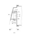
図2は、レーダー装置を取り付けたカバー部材の背面図である。図3は、図2のX-X矢視に対応する位置の断面図、図4は、図2のY-Y矢視に対応する位置の断面図、図5は、レーダー装置を取り付けたカバー部材の平面視の概略断面図である。これらの図に示すように、ヘッドライトユニット1が備えるレーダー装置40の取付構造は、ヘッドライトユニット1のハウジング10に取り付けられて、レーダー装置40の少なくとも一部を覆うカバー部材60を備えている。カバー部材60は、レーダー装置40から見て前方側に配置されている。また、カバー部材60には、該カバー部材60から後方に向かって延びるリブ71~74が形成されており、レーダー装置40は、当該リブ71~74に固定されている。なお、図5に示す点線Lは、レーダー装置40による物体の検知が可能な範囲を示すラインである。レーダー装置40は、点線Lよりも車両の前方側にある物体を検知することが可能である。 FIG. 2 is a rear view of the cover member with the radar device attached. 3 is a cross-sectional view of the position corresponding to the XX arrows in FIG. 2, FIG. 4 is a cross-sectional view of the position corresponding to the YY arrows in FIG. 2, and FIG. 5 is a cover with the radar device attached. It is a schematic sectional drawing of the planar view of a member. As shown in these figures, the mounting structure for the
カバー部材60は、外形が略矩形状で略平板状の部材であって、合成樹脂製の成型品である。カバー部材60は、ハウジング10の左側部分の前面10aに取り付けられる部材で、該カバー部材60の背面60b(ハウジング10側の面)には、レーダー装置40の上下左右の四辺それぞれに対応する4つのリブ71~74が形成されている。リブ71~74はいずれもカバー部材60の背面60bから後方に突出する薄板状の突出片である。そして、上側のリブ71には、後述するレーダー装置40の係止片42を挿入して係止させるための貫通孔(被係止部)71bが設けられている。また、下側のリブ72には、後述するレーダー装置40の締結片43を締結するためのネジ45を取り付ける取付部72bが形成されている。上記のリブ71~74で囲まれた内側の部分にカバー部材60の背面60b側からレーダー装置40を取り付けることができる。 The
また、カバー部材60の下端部には、その面が下方に向かって延びる下端辺65が設けられており、当該下端辺65には、後述するボルト66を挿通する貫通孔65aが形成されている。 A
上記構成のカバー部材60は、ハウジング10の前面10aに被せて取り付けられる。カバー部材60がハウジング10の前面10aに取り付けられることで、ハウジング10の前面10aの一部がカバー部材60で覆われた(塞がれた)状態となる。これにより、ハウジング10の前面10aとカバー部材60との間にレーダー装置40が設置される空間が画成される。 The
ここで、カバー部材60に対するレーダー装置40の取付構造の詳細について説明する。図6は、レーダー装置40を示す図で、(a)は背面図、(b)は、(a)のA-A矢視断面図である。なお、同図(b)の断面図では、レーダー装置40の内部構造の図示は省略している。同図に示すように、レーダー装置40は、略矩形状(長方形状)の外形で所定の厚み寸法を有する箱型の本体部41と、該本体部41の上下の端辺うち、上側の端辺41aに設けた係止片(係止部)42と、下側の端辺41bに設けたボルト(締結具)45(図3参照)を締結するための一対の締結片43,43とを備える。係止片42は、本体部41の上側の端辺41aの中央の一か所に形成されて上方向に突出する舌片状の突起である。一方、締結片43,43は、本体部41の下側の端辺41bにおける左右の端部近傍それぞれの二か所に形成されて下方向に突出する舌片状の突起である。締結片43,43には、ボルト45を挿通するための貫通孔43a,43aが設けられている。また、レーダー装置40の本体部41の左側の端辺41d(端面)には、配線52が繋がれたコネクタ51(図1及び図3参照)を取り付けて接続するための接続部46が設けられている。 Here, the details of the mounting structure of the
既述のように、レーダー装置40は、カバー部材60の背面60bに設けたリブ71~74に取り付ける。この際、まずレーダー装置40の係止片42をリブ71に設けた貫通孔71bに挿入して取り付けることで、係止片42をリブ71に係止する。この状態で、係止片42を支点としてレーダー装置40の本体部41をカバー部材60の背面60bに向けて回動させることで、リブ71~74で四辺を囲まれた内側の部分にレーダー装置40の本体部41を配置する。これにより、レーダー装置40の締結片43に設けた貫通孔43a,43aがカバー部材60のリブ72に設けた取付部72bに一致するので、貫通孔43aに挿通したボルト45を取付部72bに締結することで締結片43,43をリブ72にボルト45の締結で固定する。こうして、レーダー装置40の本体部41がカバー部材60の背面60bに取り付けられる。その状態でレーダー装置40の接続部46にコネクタ51を取りけることでレーダー装置40に配線52を接続する。 As described above, the
なお、交換やメンテナンスの際には、上記とは逆の手順でレーダー装置40をカバー部材60から取り外す。すなわち、まずカバー部材60をヘッドライトユニット1のハウジング10から取り外すことでカバー部材60の背面60b側にアクセスする。そして、ボルト45を取り外して、係止片42を支点としてレーダー装置40の本体部41をリブ71~74から取り出す向きに回動させる。その後、リブ71の貫通孔71bに挿入されている係止片42を取り外すことで、レーダー装置40をカバー部材60の背面60bから取り外す。 For replacement or maintenance, the
上記の手順でレーダー装置40を取り付けたカバー部材60は、ヘッドライトユニット1のハウジング10の前面10aに取り付けられる。この取り付けは、カバー部材60の下端辺65がハウジング10の前面10aにボルト66の締結で固定されるようになっている。なお、図示は省略するが、カバー部材60の上端辺には、ヘッドライトユニット1のハウジング10に係止される係止部が設けられている。当該係止部が係止された状態でボルト66の締結による固定がなされることで、カバー部材60がハウジング10に固定されるようになっている。 The
また、カバー部材60がハウジング10に固定された状態で、リブ71~74の先端部(後方側の端部)71a~74aとハウジング10の前面10aとの間には、緩衝作用を有する緩衝部材80が取り付けられている。この緩衝部材80は、柔軟性又は可撓性(伸縮性)を有するゴム材や合成樹脂材などからなる部材で、リブ71~74の先端部71a~74aとハウジング10の前面10aとの間に挟持された状態で取り付けられている。すなわち、カバー部材60がハウジング10に固定された状態で、カバー部材60のリブ71~74の先端部(後方側の端部)71a~74aがハウジング10の前面10aに緩衝部材80を介して当接している。 Further, in a state where the
本実施形態のヘッドライトユニット1が備えるレーダー装置40の取付構造は、車体側に取り付けられて、レーダー装置40の少なくとも一部を覆うカバー部材60を備え、カバー部材60は、レーダー装置40から見て前方側(レーダー装置40による物体の検知方向である第一の方向側)に配置され、カバー部材60から後方(第一の方向とは反対の方向である第二の方向)に向かって延びるリブ71~74を備え、レーダー装置40は、これらリブ71~74に固定されている。 The mounting structure of the
本実施形態の取付構造によれば、比較的に簡単な構成でありながら、カバー部材60を介してレーダー装置40が支持されることでレーダー装置40の位置決めを容易かつ精度良く行うことができると共に、カバー部材60でレーダー装置40の前方が覆われていることにより、外部からの被水などからレーダー装置40を保護することができる。したがって、レーダー装置40による物体の検知精度の向上を図ることができると共に、レーダー装置40の耐久性の向上を図ることができる。 According to the mounting structure of the present embodiment, although the structure is relatively simple, the
また、本実施形態のレーダー装置40の取付構造では、リブ71~74の先端部(後方側の端部)71a~74aが、車体側の部品であるヘッドライトユニット1のハウジング10に緩衝部材(他の部材)80を介して当接している。 In addition, in the mounting structure of the
この構成によれば、簡単な構成で、カバー部材60及びレーダー装置40の取付状態を安定させることができると共に、レーダー装置40の位置決めの精度をより高めることができる。 According to this configuration, the attachment state of the
また、この構成によれば、カバー部材60のリブ71~74が緩衝部材80を介して車体側の部品であるヘッドライトユニット1のハウジング10に当接するので、車両の走行により車体に加わる振動がカバー部材60のリブ71~74を介してレーダー装置40に伝わることを効果的に抑制することができる。したがって、レーダー装置40による物体の検知の精度をより高めることが可能となる。 Further, according to this configuration, since the
また、本実施形態のレーダー装置40の取付構造では、レーダー装置40は、その一端側にリブ71に係止される係止片(係止部)42を備え、その他端側にリブ72にボルト(締結具)45で締結固定される締結片(締結部)43,43を備えている。 In addition, in the mounting structure of the
この構成によれば、レーダー装置40の一端側に設けた係止片42をリブ71に係止して、その状態で、レーダー装置40の他端側に設けた締結片43,43をボルト45によってリブ72に締結固定することでレーダー装置40のカバー部材60への取り付けを行うことができるので、カバー部材60へのレーダー装置40の取り付け及び取り外し作業の容易化を図ることができると共に、ボルト45など締結具の数を少なく抑えることで部品点数の削減を図ることができる。 According to this configuration, the locking
以上、本発明の実施形態を説明したが、本発明は上記実施形態に限定されるものではなく、特許請求の範囲、及び明細書と図面に記載された技術的思想の範囲内において種々の変更が可能である。例えば、上記実施形態では、カバー部材60が車体に搭載されたヘッドライトユニット1のハウジング10に取り付けられている場合を示したが、本発明の取付構造が備えるカバー部材は、車体に搭載される部品(車体側の部品)であれば、ヘッドライトユニットのハウジング以外の部品に取り付けるものであってもよい。また、上記実施形態では、カバー部材のリブの先端部が緩衝部材(他の部材)を介して車体側の部品であるヘッドライトユニットのハウジングに当接している場合を示したが、これ以外にも、本発明の取付構造では、カバー部材のリブの先端部が車体側の部品に他の部材を介さず直接当接している構成であってもよい。 Although the embodiments of the present invention have been described above, the present invention is not limited to the above embodiments, and various modifications can be made within the scope of the technical ideas described in the claims, the specification and the drawings. is possible. For example, in the above-described embodiment, the
1 ヘッドライトユニット
5 光源
10 ハウジング(車体側の部品)
10a 前面
40 レーダー装置(物体検知装置)
41 本体部
41a~41d 端辺
42 係止片(係止部)
43 締結片(締結部)
43a 貫通孔
45 ボルト(締結具)
46 接続部
51 コネクタ
52 配線
60 カバー部材
60b 背面
65 下端辺
65a 貫通孔
66 ボルト(締結具)
71~74 リブ
71a~74a 先端部(第二の方向(後方)側の端部)
71b 貫通孔
72b 取付部
80 緩衝部材(他の部材)1
41
43 fastening piece (fastening part)
43a through
46 connecting
71 to 74
71b Through
Claims (5)
Translated fromJapanese前記車体側に取り付けられて、前記物体検知装置の少なくとも一部を覆うカバー部材を備え、
前記カバー部材は、前記物体検知装置から見て該物体検知装置による物体の検知方向である第一の方向側に配置され、
前記カバー部材から前記第一の方向とは反対の方向である第二の方向に向かって延びるリブを備え、
前記物体検知装置は、前記リブに固定されている
ことを特徴とする物体検知装置の車体への取付構造。A structure for mounting an object detection device for detecting an object on a vehicle body,
A cover member attached to the vehicle body side and covering at least a part of the object detection device,
The cover member is arranged on the first direction side, which is the detection direction of the object by the object detection device when viewed from the object detection device,
a rib extending from the cover member in a second direction opposite to the first direction;
The mounting structure of the object detection device to the vehicle body, wherein the object detection device is fixed to the rib.
ことを特徴とする請求項1に記載の物体検知装置の車体への取付構造。2. The mounting structure of the object detection device to the vehicle body according to claim 1, wherein the end portion of the rib on the second direction side abuts on the component on the vehicle body side directly or via another member. .
前記他の部材は、前記車体側の部品と前記カバー部材との間の緩衝作用を有する緩衝部材である
ことを特徴とする請求項1又は2に記載の物体検知装置の車体への取付構造。the ends of the ribs are in contact with parts on the vehicle body side via other members;
3. The mounting structure of the object detection device to the vehicle body according to claim 1, wherein the other member is a cushioning member having a cushioning action between the part on the vehicle body side and the cover member.
ことを特徴とする請求項1乃至3のいずれか1項に記載の物体検知装置の車体への取付構造。1 to 4, wherein the object detection device is provided with an engaging portion that is engaged with the rib on one end side thereof, and a fastening portion that is fastened and fixed to the rib by a fastener on the other end side thereof. 4. Attachment structure to the vehicle body of the object detection apparatus of any one of 3.
前記リブは、前記ハウジングに直接又は前記他の部材を介して当接している
ことを特徴とする請求項1乃至5のいずれか1項に記載の物体検知装置の車体への取付構造。The cover member is attached to a housing containing a light source of a headlight unit mounted on the vehicle body,
6. The mounting structure of the object detection device to the vehicle body according to claim 1, wherein the rib is in contact with the housing directly or via the other member.
Priority Applications (3)
| Application Number | Priority Date | Filing Date | Title |
|---|---|---|---|
| JP2021215001AJP2023098311A (en) | 2021-12-28 | 2021-12-28 | Structure to attach object detection device to vehicle body |
| US17/973,478US12366634B2 (en) | 2021-12-28 | 2022-10-25 | Mounting structure of object detection device to vehicle body |
| CN202211310583.9ACN116353492A (en) | 2021-12-28 | 2022-10-25 | Mounting structure of the object detection device to the vehicle body |
Applications Claiming Priority (1)
| Application Number | Priority Date | Filing Date | Title |
|---|---|---|---|
| JP2021215001AJP2023098311A (en) | 2021-12-28 | 2021-12-28 | Structure to attach object detection device to vehicle body |
Publications (1)
| Publication Number | Publication Date |
|---|---|
| JP2023098311Atrue JP2023098311A (en) | 2023-07-10 |
Family
ID=86897522
Family Applications (1)
| Application Number | Title | Priority Date | Filing Date |
|---|---|---|---|
| JP2021215001APendingJP2023098311A (en) | 2021-12-28 | 2021-12-28 | Structure to attach object detection device to vehicle body |
Country Status (3)
| Country | Link |
|---|---|
| US (1) | US12366634B2 (en) |
| JP (1) | JP2023098311A (en) |
| CN (1) | CN116353492A (en) |
Families Citing this family (3)
| Publication number | Priority date | Publication date | Assignee | Title |
|---|---|---|---|---|
| KR20220090169A (en)* | 2020-12-22 | 2022-06-29 | 현대자동차주식회사 | Radar support device |
| JP7365752B2 (en)* | 2022-02-17 | 2023-10-20 | 本田技研工業株式会社 | Protective structure of vehicle object detection device |
| DE102023124172A1 (en)* | 2023-09-07 | 2025-03-13 | Brose Fahrzeugteile Se & Co. Kommanditgesellschaft, Bamberg | Radar arrangement for a motor vehicle |
Citations (10)
| Publication number | Priority date | Publication date | Assignee | Title |
|---|---|---|---|---|
| JPH10261307A (en)* | 1997-03-19 | 1998-09-29 | Ichikoh Ind Ltd | Automotive lighting |
| JP2000209026A (en)* | 1999-01-12 | 2000-07-28 | Hitachi Ltd | High frequency transmitting / receiving device and in-vehicle radar system |
| JP2004312696A (en)* | 2003-03-24 | 2004-11-04 | Hitachi Ltd | Millimeter wave radar and manufacturing method thereof |
| JP2011196938A (en)* | 2010-03-23 | 2011-10-06 | Fuji Heavy Ind Ltd | In-vehicle radar system adjustment system |
| JP2012225731A (en)* | 2011-04-19 | 2012-11-15 | Mazda Motor Corp | Obstacle detection device for vehicle |
| JP2014119303A (en)* | 2012-12-14 | 2014-06-30 | Daihatsu Motor Co Ltd | On-vehicle radar device |
| JP2015063196A (en)* | 2013-09-25 | 2015-04-09 | マツダ株式会社 | Mounting structure for object detection device |
| JP2018134936A (en)* | 2017-02-21 | 2018-08-30 | 三菱自動車工業株式会社 | Radar installation structure |
| JP2020051974A (en)* | 2018-09-28 | 2020-04-02 | パナソニックIpマネジメント株式会社 | On-vehicle light device |
| JP2020197427A (en)* | 2019-05-31 | 2020-12-10 | 株式会社Soken | Collision detection sensor, on-vehicle sensor, and on-vehicle system |
Family Cites Families (7)
| Publication number | Priority date | Publication date | Assignee | Title |
|---|---|---|---|---|
| EP3552884A4 (en)* | 2016-12-09 | 2020-07-29 | Faltec Co., Ltd. | RADAR COVER AND PRODUCTION METHOD FOR A RADAR COVER |
| DE102017201660B4 (en)* | 2017-02-02 | 2025-07-17 | Robert Bosch Gmbh | Method for producing a luminous 3D radar module cover and injection molding assembly |
| WO2018146992A1 (en)* | 2017-02-09 | 2018-08-16 | 本田技研工業株式会社 | Mounting structure of external environment detection device for vehicle |
| JP7124577B2 (en) | 2018-09-06 | 2022-08-24 | トヨタ自動車株式会社 | Radar installation structure |
| JP2020051778A (en)* | 2018-09-25 | 2020-04-02 | 豊田合成株式会社 | Sealing material and sensor unit for vehicle |
| DE102020201791A1 (en)* | 2020-02-13 | 2021-08-19 | Robert Bosch Gesellschaft mit beschränkter Haftung | Sensor for the detection of objects |
| DE102020007011A1 (en)* | 2020-11-16 | 2020-12-31 | Daimler Ag | Radar sensor integrated in the vehicle headlight |
- 2021
- 2021-12-28JPJP2021215001Apatent/JP2023098311A/enactivePending
- 2022
- 2022-10-25CNCN202211310583.9Apatent/CN116353492A/enactivePending
- 2022-10-25USUS17/973,478patent/US12366634B2/enactiveActive
Patent Citations (10)
| Publication number | Priority date | Publication date | Assignee | Title |
|---|---|---|---|---|
| JPH10261307A (en)* | 1997-03-19 | 1998-09-29 | Ichikoh Ind Ltd | Automotive lighting |
| JP2000209026A (en)* | 1999-01-12 | 2000-07-28 | Hitachi Ltd | High frequency transmitting / receiving device and in-vehicle radar system |
| JP2004312696A (en)* | 2003-03-24 | 2004-11-04 | Hitachi Ltd | Millimeter wave radar and manufacturing method thereof |
| JP2011196938A (en)* | 2010-03-23 | 2011-10-06 | Fuji Heavy Ind Ltd | In-vehicle radar system adjustment system |
| JP2012225731A (en)* | 2011-04-19 | 2012-11-15 | Mazda Motor Corp | Obstacle detection device for vehicle |
| JP2014119303A (en)* | 2012-12-14 | 2014-06-30 | Daihatsu Motor Co Ltd | On-vehicle radar device |
| JP2015063196A (en)* | 2013-09-25 | 2015-04-09 | マツダ株式会社 | Mounting structure for object detection device |
| JP2018134936A (en)* | 2017-02-21 | 2018-08-30 | 三菱自動車工業株式会社 | Radar installation structure |
| JP2020051974A (en)* | 2018-09-28 | 2020-04-02 | パナソニックIpマネジメント株式会社 | On-vehicle light device |
| JP2020197427A (en)* | 2019-05-31 | 2020-12-10 | 株式会社Soken | Collision detection sensor, on-vehicle sensor, and on-vehicle system |
Also Published As
| Publication number | Publication date |
|---|---|
| US20230204712A1 (en) | 2023-06-29 |
| US12366634B2 (en) | 2025-07-22 |
| CN116353492A (en) | 2023-06-30 |
Similar Documents
| Publication | Publication Date | Title |
|---|---|---|
| JP2023098311A (en) | Structure to attach object detection device to vehicle body | |
| JP5044666B2 (en) | Mudguard mounting structure | |
| JP7355003B2 (en) | Vehicle sensor mounting structure | |
| US11807180B2 (en) | Retainer member | |
| JP2010047183A (en) | Vehicle front part structure | |
| JP2014234143A (en) | Vehicle radiator grille structure | |
| JP3201242B2 (en) | Sensor assembly and method of assembling the same | |
| US20230204761A1 (en) | Mounting structure of object detection device to vehicle body | |
| JP2004143983A (en) | Fan cover, fan cover fixing method and equipment | |
| JP3748328B2 (en) | Sensor | |
| JP2005036762A (en) | Mounting member and mounting structure for pump | |
| JP5629612B2 (en) | Vehicle front | |
| JP6192422B2 (en) | Car electronics | |
| JP2007048845A (en) | Electronic circuit unit mounting structure | |
| JP2004090687A (en) | Engine undercover | |
| JP3617277B2 (en) | Lamp mounting structure | |
| WO2017022070A1 (en) | Fan unit attachment structure and electronic device | |
| JP2004293306A (en) | Engine cover | |
| JPH10203421A (en) | Car fender protector support structure | |
| JP7636384B2 (en) | Electronics | |
| JP4630260B2 (en) | Fan unit attachment | |
| JP7544532B2 (en) | Vehicle-mounted antenna device | |
| JP2002246766A (en) | Electronic control equipment | |
| JP4375701B2 (en) | Electronics | |
| JP2022038235A (en) | On-vehicle antenna device |
Legal Events
| Date | Code | Title | Description |
|---|---|---|---|
| A621 | Written request for application examination | Free format text:JAPANESE INTERMEDIATE CODE: A621 Effective date:20220728 | |
| A131 | Notification of reasons for refusal | Free format text:JAPANESE INTERMEDIATE CODE: A131 Effective date:20230725 | |
| A521 | Request for written amendment filed | Free format text:JAPANESE INTERMEDIATE CODE: A523 Effective date:20230920 | |
| A131 | Notification of reasons for refusal | Free format text:JAPANESE INTERMEDIATE CODE: A131 Effective date:20231024 | |
| A02 | Decision of refusal | Free format text:JAPANESE INTERMEDIATE CODE: A02 Effective date:20240416 |