JP2023094895A - Malfunction prediction device, control method for malfunction prediction device and program - Google Patents
Malfunction prediction device, control method for malfunction prediction device and programDownload PDFInfo
- Publication number
- JP2023094895A JP2023094895AJP2021210474AJP2021210474AJP2023094895AJP 2023094895 AJP2023094895 AJP 2023094895AJP 2021210474 AJP2021210474 AJP 2021210474AJP 2021210474 AJP2021210474 AJP 2021210474AJP 2023094895 AJP2023094895 AJP 2023094895A
- Authority
- JP
- Japan
- Prior art keywords
- internal combustion
- failure
- probability
- power generator
- combustion power
- Prior art date
- Legal status (The legal status is an assumption and is not a legal conclusion. Google has not performed a legal analysis and makes no representation as to the accuracy of the status listed.)
- Pending
Links
Images


Landscapes
- Testing And Monitoring For Control Systems (AREA)
Abstract
Description
Translated fromJapanese本発明は、故障予測装置、故障予測装置の制御方法及びプログラムに関する。 The present invention relates to a failure prediction device, a control method for the failure prediction device, and a program.
機械や設備の故障を検知する技術として、例えば特許文献1に記載されている診断装置が知られている。 As a technique for detecting failures in machinery and equipment, for example, a diagnostic device described in
この診断装置は、動力機械が発生する動力によって駆動する第一駆動体の動作状態を検出し、第一駆動体の動作状態に応じた第一検出信号を出力する第一センサと、第一駆動体を介して伝達された動力によって駆動する第二駆動体の動作状態を検出し、第二駆動体の動作状態に応じた第二検出信号を出力する第二センサと、第二駆動体の正常状態を表す診断モデルであって、第一センサによって予め取得された第一駆動体の過去の動作状態に応じた第一検出信号と第二センサによって予め取得された第二駆動体の過去の動作状態に応じた第二検出信号とに基づいて生成されたモデル生成用データを用いて生成される診断モデルと、少なくとも第二検出信号に基づいて生成された診断用データとに基づいて、第二駆動体の動作状態を診断し、診断の結果に基づいて、第二駆動体の動作異常に関する動作異常信号を生成して出力する状態検知部と、を備える。 The diagnostic device includes a first sensor for detecting an operating state of a first driving body driven by power generated by the power machine and outputting a first detection signal corresponding to the operating state of the first driving body; a second sensor for detecting the operating state of the second driving body driven by the power transmitted through the body and outputting a second detection signal corresponding to the operating state of the second driving body; A diagnostic model representing a state, comprising: a first detection signal corresponding to a past operating state of the first driving body preliminarily acquired by a first sensor; and a past motion of the second driving body preliminarily acquired by a second sensor; Based on a diagnostic model generated using model generation data generated based on a second detection signal corresponding to the state, and diagnostic data generated based on at least the second detection signal, a second a state detection unit that diagnoses the operating state of the driver, and based on the result of the diagnosis, generates and outputs an operation abnormality signal regarding the operation abnormality of the second driver.
ところで、離島のような他の地域から地理的に分離した地域では、ディーゼルエンジンやガスタービンエンジンなどの内燃機関により発電機を駆動する内燃力発電機を用いて地域内への電力供給が行われている。 By the way, in an area geographically separated from other areas, such as a remote island, electric power is supplied to the area using an internal combustion generator driven by an internal combustion engine such as a diesel engine or a gas turbine engine. ing.
そしてこのような地域では、内燃力発電機が故障した場合には、他の地域から電力の融通を受けることができないため、予備機を起動して対処している。 In such areas, if the internal combustion power generator fails, it is not possible to receive electric power from other areas, so a standby machine is activated to deal with the problem.
しかしながら、内燃力発電機が故障した際には、予備機が発電を開始するまでに相応の時間を要する上、その間、電力供給量が減少するので地域内の電力の需給バランスが変化し電力設備に悪影響を与える可能性がある。 However, if the internal combustion generator fails, it will take a considerable amount of time for the backup generator to start generating power, and during that time, the amount of power supply will decrease, changing the supply and demand balance of power within the area, and the power facility will be damaged. may adversely affect
そのため、内燃力発電機の故障を事前に予測して、予備機への切り替えを円滑に行うことを可能にする技術が求められている。 Therefore, there is a demand for a technology that predicts a failure of the internal combustion power generator in advance and enables smooth switching to a spare machine.
本発明は上記課題を鑑みてなされたものであり、内燃力発電機の故障を予測することが可能な故障予測装置、故障予測装置の制御方法及びプログラムを提供することを目的とする。 SUMMARY OF THE INVENTION The present invention has been made in view of the above problems, and it is an object of the present invention to provide a failure prediction device capable of predicting failure of an internal combustion generator, a control method for the failure prediction device, and a program.
上記課題を解決するための手段の一つは、内燃力発電機の故障を予測する故障予測装置であって、前記内燃力発電機の運転状態と関連性を有する所定の物理量の過去の時系列データを学習データとして生成された、前記内燃力発電機が第1期間内に故障する確率を出力する学習モデルを記憶する学習モデル記憶部と、前記物理量の新たな時系列データを取得する時系列データ取得部と、前記新たな時系列データを前記学習モデルに入力することによって、第1期間内に前記内燃力発電機が故障する確率を取得する故障確率取得部と、前記確率に基づく情報を出力する故障確率出力部と、を備える。 One of the means for solving the above problems is a failure prediction device for predicting failure of an internal combustion generator, comprising: A learning model storage unit that stores a learning model that outputs a probability that the internal combustion power generator will fail within a first period, generated using data as learning data, and a time series that acquires new time series data of the physical quantity. a data acquisition unit, a failure probability acquisition unit that acquires a probability that the internal combustion generator will fail within a first period by inputting the new time-series data into the learning model, and information based on the probability. and a failure probability output unit for outputting.
その他、本願が開示する課題、およびその解決方法は、発明を実施するための形態の欄、および図面により明らかにされる。 In addition, the problem disclosed by the present application and its solution will be made clear by the description of the mode for carrying out the invention and the drawings.
本発明によれば、内燃力発電機の故障を予測することが可能になる。 According to the present invention, it becomes possible to predict a failure of an internal combustion generator.
本明細書および添付図面の記載により、少なくとも以下の事項が明らかとなる。以下、本発明をその一実施形態に即して添付図面を参照しつつ説明する。 At least the following matters will become apparent from the description of the present specification and the accompanying drawings. DESCRIPTION OF THE PREFERRED EMBODIMENTS The present invention will now be described in accordance with one embodiment thereof with reference to the accompanying drawings.
==全体構成==
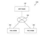
本発明の実施形態に係る故障予測システム1000の全体構成を図1に示す。== Overall configuration ==
FIG. 1 shows the overall configuration of a
故障予測システム1000は、故障予測装置100と内燃力発電機200とが、インターネットやLAN(Local Area Network)、電話網等のネットワーク500を介して通信可能に接続されて構成される。 A
内燃力発電機200は、内燃機関により発電機430を駆動することで発電を行う装置である。本実施形態に係る内燃力発電機200は、ディーゼルエンジン210により発電機430を駆動する。 The internal
図1には、2台の内燃力発電機200が示されているが、内燃力発電機200は1台でもよく3台以上でもよい。また内燃力発電機200が複数台ある場合は、そのうち少なくとも1台は、他の内燃力発電機200が故障や点検等により運転を停止した際に運転を行う予備機としてもよい。 Although two internal
内燃力発電機200は、内燃力発電機200の運転状態と関連性を有する所定の物理量(例えば発電量や燃料油の圧力など)の時系列データを、ネットワーク500を介して故障予測装置100に送信する。 The internal
なお図1には記載されていないが、内燃力発電機200は、これらの時系列データをネットワーク500を介して故障予測装置100に送信するためのコンピュータを備えている。つまり、図1には便宜上内燃力発電機200が故障予測装置100と通信可能であるように記載されているが、より正確には、この不図示のコンピュータが故障予測装置100と通信可能に接続されている。 Although not shown in FIG. 1, the
故障予測装置100は、これらの時系列データを元に、内燃力発電機200の故障を予測する情報処理装置である。 The
故障予測装置100は、内燃力発電機200から様々な物理量の時系列データを取得すると、これらの時系列データを後述する運転状況管理テーブル600に記憶する。また故障予測装置100は、内燃力発電機200の故障の有無および故障が起こった際に行った対応策(修理内容など)についても運転状況管理テーブル600に記録している。故障の有無や対応策については、内燃力発電機200の管理を行っている担当者が別途運転状況管理テーブル600に入力する。 When acquiring time-series data of various physical quantities from the
そして故障予測装置100は、これらの情報を解析することで後述する学習モデル620(AIモデル)を生成する。学習モデル620は、内燃力発電機200の運転状態と関連性を有する所定の物理量の過去の時系列データを学習データ610として生成されている。 The
そのため故障予測装置100は、運転中の内燃力発電機200の時系列データを学習モデル620に入力することで、この内燃力発電機200が第1期間内(例えば現在から3時間以内)に故障する確率を出力することができる。 Therefore, the
このような態様により、内燃力発電機200の運転状態と関連性を有する所定の物理量の時系列データに基づいて、内燃力発電機200の故障を予測することが可能になる。これにより、例えば内燃力発電機200が実際に故障する前に予備機への切り替えを行っておき、地域への電力供給を安定的に継続することが可能になる。 This aspect makes it possible to predict failure of the internal
詳細は後述する。 Details will be described later.
==内燃力発電機==
次に、本実施形態に係る内燃力発電機200について、図2を参照しながら説明する。== internal combustion generator ==
Next, the internal
内燃力発電機200は、ディーゼルエンジン210と発電機430とを備えている。ディーゼルエンジン210は、燃料油を燃焼させることにより運動エネルギーを発生させ、発電機430はこの運動エネルギーを電力に変換することで発電を行う。
内燃力発電機200は、燃料タンク220、燃料ポンプ230、燃料フィルタ240、及び燃料噴射ポンプ250を備えている。
燃料タンク220は、重油や軽油などの燃料油を貯蔵する装置である。燃料ポンプ230は、燃料タンク220から燃料油をくみ上げる装置である。燃料フィルタ240は、燃料油内に混入している異物を除去する装置である。燃料噴射ポンプ250は、ディーゼルエンジン210内の不図示の燃焼室へ燃料油を高圧噴射する装置である。
また内燃力発電機200は、吸気フィルタ260、過給機270、インタークーラー290、給気ファン280、排気温度センサ300を備えている。 The internal
吸気フィルタ260は、ディーゼルエンジン210に取り込まれる外気(給気)から異物を取り除く装置である。過給機270は、ディーゼルエンジン210からの排気を利用して不図示のタービンを回転させることで、給気を圧縮する装置である。インタークーラー290は、圧縮されて温度が上昇した給気を冷却する装置である。給気ファン280は、インタークーラー290を冷却する装置である。排気温度センサ300は、ディーゼルエンジン210から排出される排気ガスの温度を計測する。 Intake
また内燃力発電機200は、主潤滑油タンク370、主潤滑油ポンプ380、主潤滑油フィルタ390、第3熱交換器330を有している。 The internal
主潤滑油タンク370は、ディーゼルエンジン210内を潤滑する主潤滑油を貯蔵する装置である。主潤滑油ポンプ380は、主潤滑油タンク370から主潤滑油をくみ上げる装置である。主潤滑油フィルタ390は、主潤滑油内に混入している異物を除去する装置である。第3熱交換器330は、ディーゼルエンジン210から主潤滑油タンク370に戻ってくる主潤滑油を冷却する装置である。なお第3熱交換器330は、主潤滑油と中間冷却水(後述)とを熱交換することで、主潤滑油を冷却する。 Main
また内燃力発電機200は、動弁潤滑油タンク350、動弁潤滑油ポンプ360、第4熱交換器340を有している。 The
動弁潤滑油タンク350は、ディーゼルエンジン210の動弁機構を潤滑する動弁潤滑油を貯蔵する装置である。動弁潤滑油ポンプ360は、動弁潤滑油タンク350から動弁潤滑油をくみ上げる装置である。第4熱交換器340は、ディーゼルエンジン210から動弁潤滑油タンク350に戻ってくる動弁潤滑油を冷却する装置である。なお第4熱交換器340は、動弁潤滑油と中間冷却水(後述)とを熱交換することで、動弁潤滑油を冷却する。 Valve train lubricating
また内燃力発電機200は、中間冷却水ポンプ400、第2熱交換器320を有している。 The internal
中間冷却水ポンプ400は、主潤滑油及び動弁潤滑油を冷却する中間冷却水を循環させる装置である。第2熱交換器320は、中間冷却水を冷却する装置である。なお第2熱交換器320は、中間冷却水を二次水(後述する海水)と熱交換することで、中間冷却水を冷却する。 The intermediate
また内燃力発電機200は、一次水ポンプ410、第1熱交換器310を有している。一次水ポンプ410は、ディーゼルエンジン210を冷却する一次水を循環させる装置である。第1熱交換器310は、一次水を冷却する装置である。なお第1熱交換器310は、一次水を二次水(後述する海水)と熱交換することで、一次水を冷却する。 The internal
また内燃力発電機200は、二次水フィルタ420を有している。二次水フィルタ420は、一次水及び中間冷却水を冷却する海水(二次水)内の異物を除去する装置である。この二次水は、第1熱交換器310において一次水と熱交換を行うことで一次水を冷却し、第2熱交換器320において中間冷却水と熱交換を行うことで中間冷却水を冷却する。 The
また図2には示されていないが、内燃力発電機200及び内燃力発電機200が設置されている建屋(不図示)の内部及び外部には、内燃力発電機200の運転状態と関連性を有する各種の物理量を計測するための様々なセンサ及びこれらのセンサによって検出されたデータを故障予測装置100に送信するコンピュータを備えている。 In addition, although not shown in FIG. 2, inside and outside the internal
なお内燃力発電機200は、図2に示した装置以外にも様々な装置及びセンサを具備して構成されており、これらのセンサからの時系列データも故障予測装置100に送信されているが、詳細な説明は省略する。 The
==故障予測装置==
次に、故障予測装置100について説明する。== Failure prediction device ==
Next, the
故障予測装置100のハードウェア構成の一例を図3に示す。故障予測装置100は、CPU(Central Processing Unit)110、メモリ120、通信装置130、記憶装置140、入力装置150、出力装置160及び記録媒体読取装置170を有して構成されるコンピュータである。 An example of the hardware configuration of the
CPU110は故障予測装置100の全体の制御を司るもので、記憶装置140に記憶される本実施形態に係る各種の動作を行うためのコードから構成される故障予測装置制御プログラム700や各種データをメモリ120に読み出して実行あるいは処理することにより、故障予測装置100としての各種機能を実現する。 The
例えば、CPU110により故障予測装置制御プログラム700及び各種データが実行あるいは処理され、メモリ120や通信装置130、記憶装置140等のハードウェア機器と協働することにより、後述する学習モデル記憶部101、時系列データ取得部102、故障確率取得部103、故障確率出力部104などの各機能が実現される。 For example, the failure prediction
故障予測装置制御プログラム700は、故障予測装置100が有する機能を実現するためのプログラムを総称しており、例えば、故障予測装置100上で動作するアプリケーションプログラムやOS(Operating System)、種々のライブラリ等を含む。 The failure prediction
メモリ120は例えば半導体記憶装置により構成することができる。 The
記憶装置140は例えばハードディスクドライブやSSD(Solid State Drive)、フラッシュメモリ等の各種プログラムやデータ、テーブル等を記憶するための物理的な記憶領域を提供する装置である。本実施形態では、図4に示すように、記憶装置140には故障予測装置制御プログラム700の他、運転状況管理テーブル600、学習データ610、学習モデル620、推定結果630などの各種データが記憶されている。 The
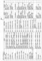
運転状況管理テーブル600の一例を図5に示す。 An example of the driving situation management table 600 is shown in FIG.
故障予測装置100には、内燃力発電機200から様々な物理量の時系列データが送信されてくるが、故障予測装置100はこれらの時系列データを取得すると、所定時間ごとに(例えば10分毎に)これらの時系列データを運転状況管理テーブル600に記憶する。また故障予測装置100は、内燃力発電機200が故障した場合には、故障した旨の情報と、故障した場所(故障した装置)、故障の対応策を含む故障情報を取得し、運転状況管理テーブル600に記憶する。故障情報は、故障発生後に行われた調査によって判明する内容が含まれており、内燃力発電機200の修理などの故障対応を行った担当者によって故障予測装置100に入力される。 Time-series data of various physical quantities are transmitted from the
故障予測装置100は、図5に示すように、所定時間毎(例えば10分毎)に時系列データと故障情報を記録している。なお故障予測装置100は、故障情報を取得していない場合は、故障が発生していない旨の情報を運転状況管理テーブル600に記録する。 As shown in FIG. 5, the
なお所定時間毎に運転状況管理テーブル600に記録される時系列データは、所定時間内の計測値の平均値であってもよいし、最大値あるいは最小値であってもよい。あるいは、平均値、最大値及び最小値を含んでもよい。あるいは、所定時間内にセンサで計測されたすべての計測値を含んでもよい(例えばセンサの計測周期が0.1秒である場合は、10分間に計測される6000個の計測値)。 The time-series data recorded in the driving situation management table 600 every predetermined time may be the average value of the measured values within the predetermined time, or may be the maximum or minimum value. Alternatively, average, maximum and minimum values may be included. Alternatively, it may include all measured values measured by the sensor within a predetermined time (for example, if the sensor measurement cycle is 0.1 seconds, 6000 measured values measured in 10 minutes).
また図5に列挙されている時系列データは一例であり、他の種類の時系列データが含まれていてもよいし、一部の時系列データは含まれていなくてもよい。 Also, the time-series data listed in FIG. 5 is an example, and other types of time-series data may be included, or part of the time-series data may not be included.
また故障予測装置100は、所定種類の気象情報を時系列データとして取得して、運転状況管理テーブル600に記憶してもよい。例えば気象情報の種類として、天候(晴れ、曇り、雨、雪、雷、ひょうなど)、気温、湿度、降水量、風速、風向、気圧などのような、内燃力発電機200の運転状態と関連性を有するものが含まれている。この場合、故障予測装置100は、ネットワーク500を介して通信可能に接続されている不図示の気象情報提供装置から、これらの気象情報を取得してもよい。 Further, the
また運転状況管理テーブル600には、内燃力発電機200の各構成要素(例えば主潤滑油フィルタ390)の使用期間や使用開始年月が時系列データとして記録されていてもよい。 The operation status management table 600 may record the period of use and the date of start of use of each component of the internal combustion power generator 200 (for example, the main lubricating oil filter 390) as time-series data.
そして時系列データの中にこれらの情報を含めることにより、学習モデル620の精度が一層向上し、故障予測装置100はより正確な故障の発生確率を出力することが可能となる。 By including these pieces of information in the time-series data, the accuracy of the
図4に戻って、故障予測装置100は、運転状況管理テーブル600に記録されている過去の第2期間(24時間、1週間、1か月等。以下、「時間区間」と称する。)の時系列データ及び故障情報に基づいて学習データ610を生成する。 Returning to FIG. 4 ,
この学習データ610を用いて学習モデル620(機械学習モデル)の学習を行うことにより、学習モデル620は、内燃力発電機200が第1期間内(例えば現在から3時間以内)に故障する確率を出力することが可能となる。 By learning the learning model 620 (machine learning model) using this
故障予測装置100は、時間区間の時系列データを説明変数(特徴量)とし、時間区間内の故障情報を目的変数(ラベル)とすることにより学習データ610を生成する。 The
上記の時間区間は、例えば、故障の頻度等に基づき、故障の予測精度が向上するような長さに経験的に設定される。また、長さの異なる複数の時間区間に対してそれぞれ学習モデル620を生成し、これらの学習モデル620を用いて故障の発生確率を算出するようにしてもよい。このような態様により、例えば時間区間の長さによって異なる故障予測精度を平準化することが可能となる。 The above-mentioned time interval is empirically set to a length that improves the failure prediction accuracy based on, for example, the frequency of failures. Alternatively, learning
あるいは故障予測装置100は、内燃力発電機200が複数ある場合、内燃力発電機200毎に学習データ610及び学習モデル620を生成してもよい。このような態様により、それぞれの内燃力発電機200に特有の学習モデル620を生成することができ、故障の発生確率の精度向上を図ることが可能となる。 Alternatively,
また同様に、故障予測装置100は学習データ610を生成する際に、特定の時期(例えば特定の季節や特定の月など)のデータを用いて学習データ610を生成してもよい。このような態様により、その時期に特有の学習モデル620を生成することができ、故障の発生確率の精度向上を図ることが可能となる。 Similarly,
さらに故障予測装置100は学習データ610を生成する際に、特定の時期のデータを用いて内燃力発電機200毎に学習データ610を生成してもよい。このような態様により、その時期に特有の学習モデル620を内燃力発電機200毎に生成することができ、故障の発生確率の精度向上を図ることが可能となる。 Furthermore, when generating learning
学習モデル620は、本実施形態ではDNN(Deep Neural Network)であるものとするが、勾配ブースティング(GBDT(Gradient Boosting Decision Tree))やオートエンコーダ等の他の種類のモデルで実現してもよい。 The
なお、オートエンコーダを用いた学習モデル620の場合は、故障情報を用いることなく、時系列データの変化をとらえることで内燃力発電機200の異変を検出することができる。 In the case of the
図7に学習モデル620の一例(ニューラルネットワークの構造)を示す。図7に示すように、学習モデル620の入力層621には時間区間内の時系列データが入力される。中間層622は、学習によって調整されるパラメータを含む一つ以上のノードからなる一つ以上の隠れ層を含む。中間層622は、入力層621に与えられた時系列データに基づき、出力層623の一つ以上の予測値(第1期間内に故障が起こる確率)を求める。出力層623は、一つ以上の予測値(故障が起こる確率)を出力する。 FIG. 7 shows an example of the learning model 620 (neural network structure). As shown in FIG. 7, an
図4に戻って、推定結果630は、学習モデル620から出力された第1期間内に故障が起こる確率に基づく情報を含む。また本実施形態に係る学習モデル620は、現在から3時間以内に故障が起こる確率と、24時間以内に故障が起こる確率と、のように複数の期間に故障が起こる確率を出力することができる。このような態様により、例えば、故障の対応策の策定や、故障対応に必要な人員や機材の準備、予備機の起動などをより効率よく行うことが可能となる。 Returning to FIG. 4,
また推定結果630には、内燃力発電機200が第1期間内に故障が起こる確率の他に、故障が予想される場所(装置)や、故障が起こった場合の対応策などが含まれていてもよい。このような態様により、内燃力発電機200のメンテナンス作業を効率化することが可能となる。 In addition to the probability that
図3に戻って、記憶装置140は、故障予測装置100に内蔵されている形態とすることもできるし、外付されている形態とすることもできる。 Returning to FIG. 3, the
記録媒体読取装置170は、CD-ROMやDVD等の記録媒体800に記録されたプログラムやデータを読み取り、記憶装置140に格納する。 The recording
通信装置130は、インターネットやLAN(Local Area Network)等のネットワーク500を介して内燃力発電機200や、不図示の他のコンピュータとデータやプログラムの授受を行う。例えば不図示の他のコンピュータに、上述した故障予測装置制御プログラム700を格納しておき、故障予測装置100がこのコンピュータから故障予測装置制御プログラム700をダウンロードして実行するようにすることができる。 The
あるいは通信装置130は、内燃力発電機200から時系列データを定期的に(例えば10分おきに)受信するようにしてもよい。また故障予測装置100は記憶装置140を備えずに、ネットワーク500を通じて通信可能に接続された不図示の他のコンピュータに記憶されている上記のプログラムやテーブル等の各種データを用いて故障予測装置100としての機能を実現する形態も可能である。 Alternatively, the
入力装置150は、担当者等による故障予測装置100へのデータ入力等のために用いられる装置でありユーザインタフェースとして機能する。入力装置150としては例えばキーボードやマウス、マイク等を用いることができる。 The
出力装置160は、情報を外部に出力するための装置でありユーザインタフェースとして機能する。出力装置160としては例えばディスプレイやプリンタ、スピーカ等を用いることができる。 The
<機能構成>
図8に、本実施形態に係る故障予測装置100の機能ブロック図を示す。故障予測装置100は、学習モデル記憶部101、時系列データ取得部102、故障確率取得部103、故障確率出力部104の各機能を備える。これらの機能は、図3に示したハードウェアによって本実施形態に係る故障予測装置制御プログラム700や各種のデータが実行あるいは処理されることにより実現される。<Functional configuration>
FIG. 8 shows a functional block diagram of the
学習モデル記憶部101は、内燃力発電機200の運転状態と関連性を有する所定の物理量の過去の時系列データを学習データ610として生成された、内燃力発電機200が第1期間内に故障する確率を出力する学習モデル620を記憶する。 The learning
例えば学習モデル620は、直近の過去の第2期間(24時間、1か月間、1年間等の時間区間)の時系列データを学習データ610として生成される。 For example, the
あるいは学習モデル620は、過去の第2期間の物理量の時系列データと、内燃力発電機200の故障有無と、を学習データ610として生成される。 Alternatively, the
あるいは学習モデル620は、過去の第2期間の物理量の時系列データと、内燃力発電機200の故障有無と、故障発生時に行った対応策の内容と、を学習データ610として生成される。この場合学習モデル620は、内燃力発電機200が第1期間内に故障する確率と、故障した場合の対応策と、を出力することができる。このような態様により、内燃力発電機200の故障対応に不慣れな担当者でも対応方法が判断できるようになる。 Alternatively, learning
あるいは学習モデル620は、過去の第2期間の物理量の時系列データと、内燃力発電機200の故障有無と、故障した部位と、故障発生時に行った対応策の内容と、を学習データ610として生成される。この場合学習モデル620は、内燃力発電機200の部位別に、第1期間内に故障する確率と、故障した場合の対応策と、を出力することができる。このような態様によれば、故障確率が部位別に得られる上、故障対応が不慣れな担当者でも対応方法が判断できるようになる。 Alternatively, the
学習モデル記憶部101は、本実施形態では記憶装置140として具現化されている。 The learning
故障予測装置100は、例えば、学習データ610を学習モデル620に入力し、それにより学習モデル620が出力する結果と入力した学習データ610との差分に基づき、学習モデル620を定義するパラメータを、例えば、誤差逆伝搬法(backpropagation)等の方法で調整することにより学習モデル620の学習を行う。 For example,
時系列データ取得部102は、上記物理量の新たな時系列データを取得する。例えば直近の過去第3期間(例えば直近の1時間)の時系列データを運転状況管理テーブル600から取得する。 The time-series
そして故障確率取得部103は、この新たな時系列データを学習モデル620に入力することによって、第1期間内(例えば3時間以内)に内燃力発電機200が故障する確率を取得する。 Then, the failure
なお学習モデル620から故障発生確率を出力する際の期間(第1期間)は、一つでも良いし複数でも良い。このような態様により、短期、中期、長期などのように、長さの異なる複数の期間における故障発生確率を担当者に提示することができる。 Note that the period (first period) for outputting the failure occurrence probability from the
あるいは、内燃力発電機200が第1期間内に故障する確率と、故障した場合の対応策と、を学習モデル620が出力できる場合は、故障確率取得部103は、故障発生確率と共に、故障した場合の対応策を取得する。 Alternatively, if the
あるいは、学習モデル620から出力される故障発生確率が、内燃力発電機200の部位別である場合には、故障確率取得部103は、例えば、故障燃料噴射ポンプ250の故障発生確率、吸気ファン280の故障発生確率、主潤滑油ポンプ380の故障発生確率、などのように、部位別に故障発生確率を取得できる。 Alternatively, when the failure occurrence probability output from the
故障確率出力部104は、確率に基づく情報を出力する。確率に基づく情報は、例えば確率の値そのものでも良いし、確率の値を所定の判定値と比較した結果に応じて、例えば故障の起こりやすさを複数段階の数値(例えば「1」「2」「3」)あるいは言葉(「問題なし」「要注意」「至急対応が必要」など)で表した情報でもよい。 The failure
また故障確率取得部103が、故障発生確率と共に、故障した場合の対応策を取得した場合には、故障確率取得部104は、内燃力発電機200が故障する確率と故障した場合の対応策とを確率に基づく情報として出力する。 When the failure
そして故障予測装置100は、例えば図11に示すような画面を出力装置160に表示することにより故障の確率に基づく情報を出力する。図11に示す例は、5台の内燃力発電機200のうち4台が稼働中である場合に、各内燃力発電機200について個別に故障発生確率を表示する場合の例である。 Then, the
以上のような態様により、内燃力発電機200の運転状態と関連性を有する所定の物理量の時系列データに基づいて、内燃力発電機200の故障を予測することが可能になる。これにより、内燃力発電機200の緊急停止の頻度が減少でき、電力供給の信頼度を向上させることが可能となる。例えば内燃力発電機200が実際に故障する前に予備機への切り替えを行っておき、電力供給を停止させないようにすることが可能になる。また内燃力発電機200の修理等の対応を、定例の点検等のタイミングに同調させることができ、作業手続きの効率化を図ることが可能となる。 With the above aspect, it is possible to predict a failure of the internal
<故障予測の例>
次に、本実施形態に係る故障予測装置100が内燃力発電機200の故障予測を行う例を、図6に示す故障予測一覧表640を参照しながら説明する。<Example of failure prediction>
Next, an example of failure prediction of the
故障予測一覧表640は、故障予測装置100が予測対象とする故障を例示的に列挙したものであり、故障予測する部位や、故障を予測するために用いる物理量などを示したものである。 The
図6に示す故障予測一覧表640には、「故障項目」「判断要素」「比較対象」「故障判定要素」「故障予測」「対応策判定」「備考」の各欄の情報が記載されている。 The
「故障項目」は、故障予測対象となる部位を示す。例えばNo1で示される故障予測では、内燃力発電機200が具備する吸気ファン280及び吸気フィルタ260が故障予測の対象である。 "Failure item" indicates a portion to be subjected to failure prediction. For example, in the failure prediction indicated by No. 1, the
「判断要素」は、故障予測を行うために学習モデル620に時系列データが入力される物理量の種類を示す。例えばNo1で示される故障予測では、「外気温度」「室内温度」「発電機出力」「発電機電流」の各時系列データが学習モデル620に入力される。なお、外気温度は、内燃力発電機200が設置される建屋の外の温度であり、室内温度は、内燃力発電機200が設置される建屋内の温度である。外気温度は、建屋の外に設置されている温度センサにより計測されたデータでもよいし、上述した気象情報提供装置から取得したデータでもよい。 “Determination element” indicates the type of physical quantity for which time-series data is input to the
「比較対象」は、各時系列データをどのデータと比較することで故障を予測するのかを示す。「過去データ」と記載されているのは、過去の時系列データと比較することで故障を予測することを示す。したがって、DNNやオートエンコーダなどのように、過去の時系列データによって学習した学習モデル620を用いて故障を予測する場合が該当する。 "Comparison target" indicates which data to compare each time-series data to predict a failure. “Past data” indicates that failures are predicted by comparison with past time-series data. Therefore, such as DNN and autoencoder, it corresponds to the case of predicting a failure using a
「故障判定要素」は、「判断要素」欄に記載されている物理量のうち、故障との関連性が最も高い物理量と、その時系列データの変化の傾向を示している。No1に示す例では、室内温度が上昇傾向にあることと、吸気ファン280あるいは吸気フィルタ260の故障との相関関係が高いことを示している。 "Failure Determining Factor" indicates the physical quantity having the highest relationship with failure among the physical quantities described in the "Determining Element" column, and the trend of change in the time-series data thereof. In the example shown in No. 1, there is a high correlation between the fact that the indoor temperature tends to rise and the failure of the
「故障予測」は、具体的に想定される故障の内容を示す。No1に示す例では、吸気ファン280の性能低下、あるいは吸気フィルタ260の詰まりが故障として想定されることを示している。 "Failure prediction" indicates details of a failure that is specifically assumed. In the example shown in No. 1, it is assumed that the performance degradation of the
「対応策判定」は、故障が起こった場合の対応策を示す。No1に示す例では、吸気ファン280の点検及び吸気フィルタ260の点検が記載されている。 "Countermeasure determination" indicates a countermeasure when a failure occurs. In the example shown in No. 1, inspection of the
図6に示す故障予測一覧表640には、No1からNo16まで16種類の故障予測が例示的に列挙されているが、本実施形態に係る故障予測装置100は、それぞれの故障に対して学習モデル620を生成して故障予測を行っている。 In the
例えばNo1の故障を予測するための学習モデル620は、外気温度と、内燃力発電機200が設置されている建屋内の温度(室内温度)と、内燃力発電機200の出力と、内燃力発電機200の電流と、の各物理量の時系列データを入力とし、吸気ファン280及び吸気フィルタ260の少なくとも一方が第1期間内に故障する確率を出力する。 For example, the
同様に、例えばNo2の故障を予測するための学習モデル620は、外気温度と、内燃力発電機200が設置されている建屋内の温度(室内温度)と、内燃力発電機200の出力と、内燃力発電機200の電流と、燃料ポンプ230によって供給される燃料油の圧力と、の各物理量の時系列データを入力とし、燃料ポンプ230が第1期間内に故障する確率を出力する。 Similarly, the
また例えばNo3の故障を予測するための学習モデル620は、外気温度と、内燃力発電機200が設置されている建屋内の温度(室内温度)と、内燃力発電機200の出力と、燃料ポンプ230によって供給される燃料油の圧力と、燃料油から不純物を除去する燃料フィルタ(燃料濾器)240の上流側及び下流側の差圧と、の各物理量の時系列データを入力とし、燃料フィルタ240が第1期間内に故障する確率を出力する。 Further, for example, the
また例えばNo4の故障を予測するための学習モデル620は、外気温度と、内燃力発電機200が設置されている建屋内の温度(室内温度)と、内燃力発電機200の出力と、内燃力発電機200の電流と、主潤滑油ポンプ380によって供給される主潤滑油の圧力と、主潤滑油の温度と、の各物理量の時系列データを入力とし、主潤滑油ポンプ380が第1期間内に故障する確率を出力する。 Further, for example, the
以下、No16まで同様であるため詳細な説明は省略するが、このように、内燃力発電機200を構成する部位別に学習モデル620を生成することにより、その部位に故障が発生する際の特徴をより的確にとらえることができ、より正確に故障を予測することが可能となる。 Hereinafter, since the same is true up to No. 16, a detailed description will be omitted, but by generating the
また故障予測装置100は、内燃力発電機200の複数の部位の学習モデル620のそれぞれの出力結果(確率)を入力とし、内燃力発電機200全体としての運転状態の予測を行う学習モデル620を有してもよい。 Further, the
この場合、例えば、説明変数(特徴量)が上記の各部位が故障する確率であり、目的変数(ラベル)が内燃力発電機200の運転状態を示す情報(例えば排気ガス内の特定成分の量、成分比、騒音レベル、騒音のスペクトルなど)であるような学習データ610を生成し、この学習データ610を用いて学習モデル620を生成する。 In this case, for example, the explanatory variable (feature quantity) is the probability of failure of each part described above, and the objective variable (label) is information indicating the operating state of the internal combustion generator 200 (for example, the amount of a specific component in the exhaust gas). , component ratio, noise level, noise spectrum, etc.) is generated, and a
このような態様により、例えば、排気ガスの成分の変化や、騒音の増加など、故障とまでは言えないような内燃力発電機200の状態の変化を予測することも可能となる。 Such a mode makes it possible to predict changes in the state of the
==処理の流れ==
次に、図9~図10を参照しながら、本実施形態に係る故障予測装置100が学習データ610を用いて学習モデル620の学習を行う処理と、この学習モデル620を用いて内燃力発電機200が故障する確率を算出する際の処理の流れを説明する。== Process flow ==
Next, referring to FIGS. 9 and 10, the
図9は、故障予測装置100が学習データ610を用いて学習モデル620の学習を行う際の処理を説明するフローチャートである。尚、故障予測装置100が学習モデル620の学習を実行するタイミングは必ずしも限定されないが、例えば、運転状況管理テーブル600に新たな時系列データが追加されたタイミングや、ユーザインタフェースを介して担当者から学習の実行指示を受け付けたタイミング、あるいは、所定期間毎(1か月に1回、1年に1回など)に到来する所定のタイミングなどを契機として、故障予測装置100は学習モデル620の学習処理を実行する。 FIG. 9 is a flowchart for explaining processing when
まず故障予測装置100は、時間区間内の時系列データと、故障の有無及び対応策と、を対応づけたデータを学習データ610として生成する(S1000)。故障予測装置100は、運転状況管理テーブル600からこれらの情報を取得することができる。 First, the
次に故障予測装置100は、学習データ610を用いて学習モデル620の学習処理を行う(S1010)。 Next, the
尚、故障予測装置100は、学習済の学習モデル620について予測精度の検証を行うようにしてもよい。その場合、故障予測装置100は、学習データ610を学習用のデータと検証用のデータに予め分類しておき、学習用のデータを用いて学習モデル620の学習を行い、検証用のデータを用いて学習モデル620の検証を行うようにする。 Note that the
図10は、内燃力発電機200が故障する確率を故障予測装置100が算出する際の処理を説明するフローチャートである。 FIG. 10 is a flowchart for explaining the processing when the
まず故障予測装置100は、運転状況管理テーブル600を参照し、内燃力発電機200の運転状態に影響する物理量の時系列データを取得する(S2000)。例えば故障予測装置100は、直近の過去3時間分の時系列データを取得する。 First, the
続いて故障予測装置100は、この時系列データを学習モデル620に入力し、学習モデル620から出力される故障の確率を取得する(S2010)。 Subsequently, the
そして故障予測装置100は、図11に示したような故障の発生確率に基づく情報を記載した画面を生成し、生成した画面を出力装置160に出力する(S2020)。 Then, the
このような態様により、内燃力発電機200の運転状態と関連性を有する所定の物理量の時系列データに基づいて、内燃力発電機200の故障を予測することが可能になる。これにより、内燃力発電機200の緊急停止の頻度が減少でき、電力供給の信頼度を向上させることが可能となる。例えば内燃力発電機200が実際に故障する前に予備機への切り替えを行っておき、電力供給を停止させないようにすることが可能になる。また内燃力発電機200の修理等の対応を、定例の点検等のタイミングに同調させることができ、作業手続きの効率化を図ることが可能となる。 This aspect makes it possible to predict failure of the internal
以上、本実施形態に係る故障予測装置100、故障予測装置100の制御方法及びプログラムについて説明したが、本実施形態によれば、内燃力発電機200の故障を予測することが可能になる。 The
なお上述した実施の形態は本発明の理解を容易にするためのものであり、本発明を限定して解釈するためのものではない。本発明はその趣旨を逸脱することなく変更、改良され得るとともに、本発明にはその等価物も含まれる。 The above-described embodiments are intended to facilitate understanding of the present invention, and are not intended to limit and interpret the present invention. The present invention may be modified and improved without departing from its spirit, and the present invention also includes equivalents thereof.
100 故障予測装置
101 学習モデル記憶部
102 時系列データ取得部
103 故障確率取得部
104 故障確率出力部
110 CPU
120 メモリ
130 通信装置
140 記憶装置
150 入力装置
160 出力装置
170 記録媒体読取装置
200 内燃力発電機
210 ディーゼルエンジン
220 燃料タンク
230 燃料ポンプ
240 燃料フィルタ
250 燃料噴射ポンプ
260 吸気フィルタ
270 過給機
280 給気ファン
290 インタークーラー
300 排気温度センサ
310 第1熱交換器
320 第2熱交換器
330 第3熱交換器
340 第4熱交換器
350 動弁潤滑油タンク
360 動弁潤滑油ポンプ
370 主潤滑油タンク
380 主潤滑油ポンプ
390 主潤滑油フィルタ
400 中間冷却水ポンプ
410 一次水ポンプ
420 二次水フィルタ
430 発電機
500 ネットワーク
600 運転状況管理テーブル
610 学習データ
620 学習モデル
621 入力層
622 中間層
623 出力層
630 推定結果
640 故障予測一覧表
700 故障予測装置制御プログラム
800 記録媒体
1000 故障予測システム100
120
Claims (10)
Translated fromJapanese前記内燃力発電機の運転状態と関連性を有する所定の物理量の過去の時系列データを学習データとして生成された、前記内燃力発電機が第1期間内に故障する確率を出力する学習モデルを記憶する学習モデル記憶部と、
前記物理量の新たな時系列データを取得する時系列データ取得部と、
前記新たな時系列データを前記学習モデルに入力することによって、第1期間内に前記内燃力発電機が故障する確率を取得する故障確率取得部と、
前記確率に基づく情報を出力する故障確率出力部と、
を備える故障予測装置。A failure prediction device for predicting failure of an internal combustion generator,
A learning model that outputs a probability that the internal combustion power generator will fail within a first period, generated as learning data from past time-series data of a predetermined physical quantity that is related to the operating state of the internal combustion power generator. a learning model storage unit for storing;
a time-series data acquisition unit that acquires new time-series data of the physical quantity;
a failure probability acquisition unit that acquires a probability that the internal combustion generator will fail within a first period by inputting the new time-series data into the learning model;
a failure probability output unit that outputs information based on the probability;
A failure prediction device.
前記学習モデルは、過去の第2期間の前記物理量の時系列データと、前記内燃力発電機の故障有無と、を学習データとして生成されてなる、故障予測装置。The failure prediction device according to claim 1,
The failure prediction device, wherein the learning model is generated from time-series data of the physical quantity for a past second period and whether or not the internal combustion generator has failed as learning data.
前記学習モデルは、過去の第2期間の前記物理量の時系列データと、前記内燃力発電機の故障有無と、故障発生時に行った対応策の内容と、を学習データとして生成されてなり、前記内燃力発電機が第1期間内に故障する確率と、故障した場合の対応策と、を出力し、
前記故障確率取得部は、
前記新たな時系列データを前記学習モデルに入力することによって、第1期間内に前記内燃力発電機が故障する確率と、故障した場合の対応策と、を取得し、
前記故障確率取得部は、
前記確率に基づく情報として、前記内燃力発電機が故障する確率と、故障した場合の対応策と、を出力する、故障予測装置。The failure prediction device according to claim 1,
The learning model is generated as learning data from the time-series data of the physical quantity in the past second period, whether or not there is a failure in the internal combustion power generator, and details of countermeasures taken when the failure occurred, and outputting the probability that the internal combustion generator will fail within the first period and the countermeasures to be taken in the event of failure;
The failure probability acquisition unit,
By inputting the new time-series data into the learning model, obtaining the probability that the internal combustion generator will fail within the first period and countermeasures in case of failure,
The failure probability acquisition unit,
A failure prediction device that outputs, as information based on the probability, a probability that the internal combustion generator will fail and measures to be taken in the event of failure.
前記物理量には、外気温度と、前記内燃力発電機が設置されている建屋内の温度と、前記内燃力発電機の出力と、前記内燃力発電機の電流と、が含まれ、
前記学習モデルは、前記内燃力発電機が具備する吸気ファン及び吸気フィルタの少なくとも一方が第1期間内に故障する確率を出力する、故障予測装置。The failure prediction device according to any one of claims 1 to 3,
The physical quantity includes an outside air temperature, a temperature in the building where the internal combustion power generator is installed, an output of the internal combustion power generator, and a current of the internal combustion power generator,
The failure prediction device, wherein the learning model outputs a probability that at least one of an intake fan and an intake filter of the internal combustion power generator will fail within a first period.
前記物理量には、外気温度と、前記内燃力発電機が設置されている建屋内の温度と、前記内燃力発電機の出力と、前記内燃力発電機の電流と、前記内燃力発電機が具備する燃料ポンプによって供給される燃料油の圧力と、が含まれ、
前記学習モデルは、前記燃料ポンプが第1期間内に故障する確率を出力する、故障予測装置。The failure prediction device according to any one of claims 1 to 3,
The physical quantity includes an outside air temperature, a temperature inside the building where the internal combustion power generator is installed, an output of the internal combustion power generator, a current of the internal combustion power generator, and the internal combustion power generator. and the pressure of the fuel oil supplied by the fuel pump to
The failure prediction device, wherein the learning model outputs a probability that the fuel pump will fail within a first period.
前記物理量には、外気温度と、前記内燃力発電機が設置されている建屋内の温度と、前記内燃力発電機の出力と、前記内燃力発電機が具備する燃料ポンプによって供給される燃料油の圧力と、前記内燃力発電機が具備する前記燃料油から不純物を除去する燃料濾器の上流側及び下流側の差圧と、が含まれ、
前記学習モデルは、前記燃料濾器が第1期間内に故障する確率を出力する、故障予測装置。The failure prediction device according to any one of claims 1 to 3,
The physical quantities include the outside air temperature, the temperature in the building where the internal combustion power generator is installed, the output of the internal combustion power generator, and the fuel oil supplied by the fuel pump provided in the internal combustion power generator. and a differential pressure upstream and downstream of a fuel filter that removes impurities from the fuel oil provided by the internal combustion generator;
The failure prediction device, wherein the learning model outputs a probability that the fuel filter will fail within a first time period.
前記物理量には、外気温度と、前記内燃力発電機が設置されている建屋内の温度と、前記内燃力発電機の出力と、前記内燃力発電機の電流と、前記内燃力発電機が具備する主潤滑油ポンプによって供給される主潤滑油の圧力と、前記主潤滑油の温度と、が含まれ、
前記学習モデルは、前記主潤滑油ポンプが第1期間内に故障する確率を出力する、故障予測装置。The failure prediction device according to any one of claims 1 to 3,
The physical quantity includes an outside air temperature, a temperature inside the building where the internal combustion power generator is installed, an output of the internal combustion power generator, a current of the internal combustion power generator, and the internal combustion power generator. the pressure of the main lubricant supplied by the main lubricant pump and the temperature of said main lubricant;
The failure prediction device, wherein the learning model outputs a probability that the main lubricating oil pump will fail within a first time period.
前記物理量には、外気温度と、前記内燃力発電機が設置されている建屋内の温度と、前記内燃力発電機の出力と、前記内燃力発電機の電流と、前記内燃力発電機が具備する主潤滑油ポンプによって供給される主潤滑油の圧力と、前記主潤滑油の温度と、前記内燃力発電機が具備する前記主潤滑油から不純物を除去する主潤滑油濾器の上流側及び下流側の差圧と、が含まれ、
前記学習モデルは、前記主潤滑油濾器が第1期間内に故障する確率を出力する、故障予測装置。The failure prediction device according to any one of claims 1 to 3,
The physical quantity includes an outside air temperature, a temperature inside the building where the internal combustion power generator is installed, an output of the internal combustion power generator, a current of the internal combustion power generator, and the internal combustion power generator. the pressure of the main lubricating oil supplied by a main lubricating oil pump, the temperature of said main lubricating oil, and upstream and downstream of a main lubricating oil filter provided by said internal combustion generator for removing impurities from said main lubricating oil. side differential pressure, and
The failure predictor, wherein the learning model outputs a probability that the main lubricating oil filter will fail within a first time period.
前記故障予測装置が、
前記内燃力発電機の運転状態と関連性を有する所定の物理量の過去の時系列データを学習データとして生成された、前記内燃力発電機が第1期間内に故障する確率を出力する学習モデルを記憶し、
前記物理量の新たな時系列データを取得し、
前記新たな時系列データを前記学習モデルに入力することによって、第1期間内に前記内燃力発電機が故障する確率を取得し、
前記確率に基づく情報を出力する、
故障予測装置の制御方法。A control method for a failure prediction device that predicts failure of an internal combustion generator, comprising:
The failure prediction device
A learning model that outputs a probability that the internal combustion power generator will fail within a first period, generated as learning data from past time-series data of a predetermined physical quantity that is related to the operating state of the internal combustion power generator. remember,
Acquiring new time-series data of the physical quantity,
Obtaining the probability that the internal combustion generator will fail within a first period by inputting the new time-series data into the learning model;
outputting information based on said probability;
A control method for a failure prediction device.
前記内燃力発電機の運転状態と関連性を有する所定の物理量の過去の時系列データを学習データとして生成された、前記内燃力発電機が第1期間内に故障する確率を出力する学習モデルを記憶する機能と、
前記物理量の新たな時系列データを取得する機能と、
前記新たな時系列データを前記学習モデルに入力することによって、第1期間内に前記内燃力発電機が故障する確率を取得する機能と、
前記確率に基づく情報を出力する機能と、
を実現するためのプログラム。A computer that predicts the failure of an internal combustion generator,
A learning model that outputs a probability that the internal combustion power generator will fail within a first period, generated as learning data from past time-series data of a predetermined physical quantity that is related to the operating state of the internal combustion power generator. the ability to remember and
A function of acquiring new time-series data of the physical quantity;
a function of obtaining the probability that the internal combustion generator will fail within a first period by inputting the new time-series data into the learning model;
a function of outputting information based on the probability;
A program to realize
Priority Applications (1)
| Application Number | Priority Date | Filing Date | Title |
|---|---|---|---|
| JP2021210474AJP2023094895A (en) | 2021-12-24 | 2021-12-24 | Malfunction prediction device, control method for malfunction prediction device and program |
Applications Claiming Priority (1)
| Application Number | Priority Date | Filing Date | Title |
|---|---|---|---|
| JP2021210474AJP2023094895A (en) | 2021-12-24 | 2021-12-24 | Malfunction prediction device, control method for malfunction prediction device and program |
Publications (1)
| Publication Number | Publication Date |
|---|---|
| JP2023094895Atrue JP2023094895A (en) | 2023-07-06 |
Family
ID=87002148
Family Applications (1)
| Application Number | Title | Priority Date | Filing Date |
|---|---|---|---|
| JP2021210474APendingJP2023094895A (en) | 2021-12-24 | 2021-12-24 | Malfunction prediction device, control method for malfunction prediction device and program |
Country Status (1)
| Country | Link |
|---|---|
| JP (1) | JP2023094895A (en) |
Cited By (1)
| Publication number | Priority date | Publication date | Assignee | Title |
|---|---|---|---|---|
| CN117445403A (en)* | 2023-12-26 | 2024-01-26 | 深圳市智能派科技有限公司 | 3D printing fault monitoring method and system based on current prediction |
Citations (8)
| Publication number | Priority date | Publication date | Assignee | Title |
|---|---|---|---|---|
| JP2007026134A (en)* | 2005-07-19 | 2007-02-01 | Matsushita Electric Works Ltd | Abnormality decision device |
| JP2010203330A (en)* | 2009-03-04 | 2010-09-16 | Denso Corp | Device for diagnosing abnormality of fuel supply path |
| JP2013041448A (en)* | 2011-08-17 | 2013-02-28 | Hitachi Ltd | Method of abnormality detection/diagnosis and system of abnormality detection/diagnosis |
| JP2016218961A (en)* | 2015-05-26 | 2016-12-22 | 株式会社日立パワーソリューションズ | Abnormality sign diagnosis device and abnormality sign diagnosis method |
| JP2017215832A (en)* | 2016-06-01 | 2017-12-07 | 株式会社神戸製鋼所 | Diagnosis device for diagnosing operational state of rotary machine, and diagnosis method |
| JP2018076863A (en)* | 2016-09-12 | 2018-05-17 | ゼネラル・エレクトリック・カンパニイ | System and method for condition-based monitoring of turbine filter |
| JP2020030757A (en)* | 2018-08-24 | 2020-02-27 | パナソニックIpマネジメント株式会社 | Failure location diagnosis system, failure location diagnosis method, and program |
| WO2020123420A1 (en)* | 2018-12-11 | 2020-06-18 | General Electric Company | Methods and systems for automated condition-based maintenance of mechanical systems |
- 2021
- 2021-12-24JPJP2021210474Apatent/JP2023094895A/enactivePending
Patent Citations (8)
| Publication number | Priority date | Publication date | Assignee | Title |
|---|---|---|---|---|
| JP2007026134A (en)* | 2005-07-19 | 2007-02-01 | Matsushita Electric Works Ltd | Abnormality decision device |
| JP2010203330A (en)* | 2009-03-04 | 2010-09-16 | Denso Corp | Device for diagnosing abnormality of fuel supply path |
| JP2013041448A (en)* | 2011-08-17 | 2013-02-28 | Hitachi Ltd | Method of abnormality detection/diagnosis and system of abnormality detection/diagnosis |
| JP2016218961A (en)* | 2015-05-26 | 2016-12-22 | 株式会社日立パワーソリューションズ | Abnormality sign diagnosis device and abnormality sign diagnosis method |
| JP2017215832A (en)* | 2016-06-01 | 2017-12-07 | 株式会社神戸製鋼所 | Diagnosis device for diagnosing operational state of rotary machine, and diagnosis method |
| JP2018076863A (en)* | 2016-09-12 | 2018-05-17 | ゼネラル・エレクトリック・カンパニイ | System and method for condition-based monitoring of turbine filter |
| JP2020030757A (en)* | 2018-08-24 | 2020-02-27 | パナソニックIpマネジメント株式会社 | Failure location diagnosis system, failure location diagnosis method, and program |
| WO2020123420A1 (en)* | 2018-12-11 | 2020-06-18 | General Electric Company | Methods and systems for automated condition-based maintenance of mechanical systems |
Cited By (2)
| Publication number | Priority date | Publication date | Assignee | Title |
|---|---|---|---|---|
| CN117445403A (en)* | 2023-12-26 | 2024-01-26 | 深圳市智能派科技有限公司 | 3D printing fault monitoring method and system based on current prediction |
| CN117445403B (en)* | 2023-12-26 | 2024-03-26 | 深圳市智能派科技有限公司 | 3D printing fault monitoring method and system based on current prediction |
Similar Documents
| Publication | Publication Date | Title |
|---|---|---|
| US11308250B2 (en) | Learning expected operational behavior of machines from generic definitions and past behavior | |
| US7062370B2 (en) | Model-based detection, diagnosis of turbine engine faults | |
| CN107111309B (en) | Gas turbine fault prediction using supervised learning methods | |
| Zhou et al. | A novel grey prognostic model based on Markov process and grey incidence analysis for energy conversion equipment degradation | |
| KR101955305B1 (en) | Gas turbine sensor failure detection utilizing a sparse coding methodology | |
| CN106404403B (en) | Method and system for analysis of turbines | |
| Steurtewagen et al. | Adding interpretability to predictive maintenance by machine learning on sensor data | |
| Olsson et al. | A data-driven approach for predicting long-term degradation of a fleet of micro gas turbines | |
| JP2021022290A (en) | Control state monitoring system and program | |
| JP2006057595A (en) | Gas turbine performance diagnosis system and performance diagnosis method | |
| Santos et al. | Big data analytics for predictive maintenance modeling: Challenges and opportunities | |
| JP2023094895A (en) | Malfunction prediction device, control method for malfunction prediction device and program | |
| Fentaye et al. | Hybrid model-based and data-driven diagnostic algorithm for gas turbine engines | |
| Adamowicz et al. | Advanced gas turbines health monitoring systems | |
| Li et al. | A novel machine learning based fault diagnosis method for all gas-path components of heavy duty gas turbines with the aid of thermodynamic model | |
| JP7483709B2 (en) | Method and system for automated condition-based maintenance of mechanical systems - Patents.com | |
| Perera et al. | Failure intensity of offshore power plants under varying maintenance policies | |
| Eustace | A real-world application of fuzzy logic and influence coefficients for gas turbine performance diagnostics | |
| Walker et al. | Nuclear Power Fault Diagnostics and Preventative Maintenance Optimization | |
| Maraini et al. | Development of a data-driven model for marine gas turbine (MGT) engine health monitoring | |
| Machado et al. | RUL modeling for turbo generators of a FPSO: Alternatives and challenges | |
| WO2018003028A1 (en) | Boiler failure determining device, failure determining method, and service method | |
| Roemer et al. | Real-time health monitoring and diagnostics for gas turbine engines | |
| Zhang | A brief review of condition monitoring techniques for gas turbines | |
| RU2780968C1 (en) | Method and system for monitoring equipment based on joint statistical and physical modelling |
Legal Events
| Date | Code | Title | Description |
|---|---|---|---|
| A621 | Written request for application examination | Free format text:JAPANESE INTERMEDIATE CODE: A621 Effective date:20241024 | |
| A977 | Report on retrieval | Free format text:JAPANESE INTERMEDIATE CODE: A971007 Effective date:20250416 | |
| A131 | Notification of reasons for refusal | Free format text:JAPANESE INTERMEDIATE CODE: A131 Effective date:20250520 | |
| A521 | Request for written amendment filed | Free format text:JAPANESE INTERMEDIATE CODE: A523 Effective date:20250606 | |
| A02 | Decision of refusal | Free format text:JAPANESE INTERMEDIATE CODE: A02 Effective date:20250930 |