JP2023091381A - Apparatus and method for manufacturing gallium nitride layer - Google Patents
Apparatus and method for manufacturing gallium nitride layerDownload PDFInfo
- Publication number
- JP2023091381A JP2023091381AJP2021206095AJP2021206095AJP2023091381AJP 2023091381 AJP2023091381 AJP 2023091381AJP 2021206095 AJP2021206095 AJP 2021206095AJP 2021206095 AJP2021206095 AJP 2021206095AJP 2023091381 AJP2023091381 AJP 2023091381A
- Authority
- JP
- Japan
- Prior art keywords
- gas
- gallium
- space
- chlorine gas
- growth
- Prior art date
- Legal status (The legal status is an assumption and is not a legal conclusion. Google has not performed a legal analysis and makes no representation as to the accuracy of the status listed.)
- Pending
Links
Images

Landscapes
- Crystals, And After-Treatments Of Crystals (AREA)
- Recrystallisation Techniques (AREA)
Abstract
Description
Translated fromJapanese本発明は、窒化ガリウム(以下では、単にGaNともいう)で構成される種基板上にGaN層を成長させるGaN層製造装置およびGaN層の製造方法に関するものである。 The present invention relates to a GaN layer manufacturing apparatus and a GaN layer manufacturing method for growing a GaN layer on a seed substrate made of gallium nitride (hereinafter also simply referred to as GaN).
従来より、ハイドライド気層成長法を用い、GaNで構成される種基板上にGaN層を成長させるGaN層製造装置およびその製造方法が提案されている(例えば、特許文献1参照)。具体的には、この製造装置では、種基板が配置されてGaN層を成長させる成長装置と、GaN層を成長させるための原料ガスとなる三塩化ガリウムガスを生成する生成装置とを備えている。また、この製造装置では、成長装置と生成装置とを繋いで生成装置で生成されたガスを成長装置へ供給する第1供給配管と、GaN層を成長させるための原料ガスとなるアンモニアガスを成長装置へ供給する第2供給配管とを備えている。 2. Description of the Related Art Conventionally, a GaN layer manufacturing apparatus and a manufacturing method thereof have been proposed for growing a GaN layer on a seed substrate made of GaN using a hydride vapor layer epitaxy method (see, for example, Patent Document 1). Specifically, this manufacturing apparatus includes a growth apparatus in which a seed substrate is arranged to grow a GaN layer, and a generation apparatus for generating gallium trichloride gas as a raw material gas for growing the GaN layer. . In addition, in this manufacturing apparatus, a first supply pipe that connects the growth apparatus and the generation apparatus to supply the gas generated by the generation apparatus to the growth apparatus, and an ammonia gas that serves as a raw material gas for growing the GaN layer. and a second supply line feeding the device.
成長装置は、種基板が配置される成長用容器を有し、生成装置で生成された三塩化ガリウムガスが第1供給配管を介して成長用容器内に供給されるように構成されている。また、成長装置は、アンモニアガスが第2供給配管を介して成長用容器内に供給されるように構成されている。 The growth apparatus has a growth vessel in which the seed substrate is placed, and is configured such that gallium trichloride gas generated by the generation apparatus is supplied into the growth vessel through a first supply pipe. Further, the growth apparatus is configured such that ammonia gas is supplied into the growth container through the second supply pipe.
生成装置は、金属ガリウムが配置される生成用容器を備えている。生成用容器は、金属ガリウムが配置される第1空間と、第1空間と連通した第2空間とを備える構成とされている。また、生成用容器は、第1空間に塩素ガスを誘導するための第1誘導配管、および第2空間に塩素ガスを誘導するための第2誘導配管が備えられている。 The generator comprises a generator vessel in which metallic gallium is placed. The production container is configured to include a first space in which metallic gallium is placed and a second space communicating with the first space. The production vessel is also provided with a first guide pipe for guiding the chlorine gas to the first space and a second guide pipe for guiding the chlorine gas to the second space.
そして、生成装置では、第1誘導配管から塩素ガスが誘導されると、下記化学式1の反応のように、金属ガリウムと塩素ガスとが反応して一塩化ガリウムガスが生成される。 In the generation device, when chlorine gas is introduced from the first induction pipe, metal gallium reacts with chlorine gas to generate gallium monochloride gas, as in the reaction of Chemical Formula 1 below.
(化1)Ga+1/2Cl2→GaCl
また、生成装置では、生成用容器に第2誘導配管から塩素ガスが誘導されると、下記化学式2のように、一塩化ガリウムガスと塩素ガスとが反応して三塩化ガリウムガスが生成される。(Chemical Formula 1) Ga+1/2Cl2 →GaCl
In addition, in the generation device, when chlorine gas is guided from the second induction pipe to the generation container, gallium monochloride gas and chlorine gas react to generate gallium trichloride gas as shown in chemical formula 2 below. .
(化2)GaCl+Cl2→GaCl3
なお、生成装置で三塩化ガリウムガスが生成される際、生成装置は、第1空間が800~900℃程度となり、第2空間のうちの第1供給配管側の部分が150℃程度となるように加熱される。また、第1供給配管は、150℃程度となるように加熱される。(Formula 2) GaCl+Cl2 →GaCl3
When gallium trichloride gas is generated by the generation device, the generation device is set so that the temperature of the first space is about 800 to 900°C, and the temperature of the second space on the side of the first supply pipe is about 150°C. is heated to Also, the first supply pipe is heated to about 150°C.
そして、このようなGaN層製造装置では、種基板上に、三塩化ガリウムガスおよびアンモニアガスが供給されることにより、下記化学式3の反応によってGaN層が成長させられる。 In such a GaN layer manufacturing apparatus, gallium trichloride gas and ammonia gas are supplied onto the seed substrate to grow a GaN layer by the reaction of
(化3)GaCl3+NH3→GaN+3HCl(Chemical Formula 3) GaCl3 +NH3 →GaN+3HCl
ところで、一塩化ガリウムは、三塩化ガリウムよりも沸点が高く、固化し易い材料である。このため、第1供給配管を介して三塩化ガリウムガスを成長装置内へ供給する際、一塩化ガリウムガスが残存していると、第1供給配管内で一塩化ガリウムガスが固化してしまう可能性があり、第1供給配管内が閉塞される可能性がある。 By the way, gallium monochloride has a higher boiling point than gallium trichloride and is a material that solidifies easily. For this reason, when gallium trichloride gas is supplied into the growth apparatus through the first supply pipe, if gallium monochloride gas remains, gallium monochloride gas may solidify in the first supply pipe. There is a possibility that the inside of the first supply pipe will be blocked.
本発明は上記点に鑑み、三塩化ガリウムガスを供給する供給配管が閉塞することを抑制できるGaN層製造装置およびGaN層の製造方法を提供することを目的とする。 SUMMARY OF THE INVENTION In view of the above points, it is an object of the present invention to provide a GaN layer manufacturing apparatus and a GaN layer manufacturing method capable of suppressing clogging of a supply pipe for supplying gallium trichloride gas.
上記目的を達成するための請求項1では、GaNで構成される種基板(121)上にガリウム系ガスおよびアンモニア系ガスを供給することでGaN層(122)を成長させるGaN層製造装置であって、反応室を構成する中空部(101a)でGaN層が成長させられる筒状の成長用容器(100)を有する成長装置(10)と、成長用容器の中空部内に配置され、GaN層が成長させられる種基板が配置される台座(120)と、ガリウム系ガスとしての三塩化ガリウムガスを生成する生成装置(20)と、生成装置と成長装置とを繋ぎ、生成装置で生成された三塩化ガリウムガスを成長装置へ供給する供給配管(310)と、を備え、生成装置は、金属ガリウム(220)が配置される第1空間(211)および第1空間と供給配管との間に位置する第2空間(212)と、第1空間に塩素ガスを誘導する第1誘導配管(231)と、第2空間に塩素ガスを誘導する第2誘導配管(232)と、を有し、第2誘導配管は、第1誘導配管から塩素ガスが誘導されることで生成された一塩化ガリウムガスを三塩化ガリウムガスにするのに必要な塩素ガスの量よりも多い塩素ガスが誘導されるようになっている。
これによれば、一塩化ガリウムガスが残存することを抑制でき、一塩化ガリウムガスが固化して供給配管が閉塞することを抑制しつつ、GaN層を成長させることができる。 According to this, it is possible to suppress the gallium monochloride gas from remaining, and to grow the GaN layer while suppressing clogging of the supply pipe due to solidification of the gallium monochloride gas.
また、請求項4は、請求項1に記載のGaN層製造装置を用いたGaN層の製造方法であり、請求項1に記載のGaN層製造装置を用意することと、生成装置で三塩化ガリウムガスを生成してGaN層を成長させることと、を行い、三塩化ガリウムガスを生成することでは、第1誘導配管から塩素ガスを誘導して金属ガリウムと塩素ガスを反応させて一塩化ガリウムガスを生成することと、第2誘導配管から塩素ガスを誘導し、一塩化ガリウムガスと塩素ガスとを反応させて三塩化ガリウムガスを生成することと、を行い、第2誘導配管から塩素ガスを誘導することでは、一塩化ガリウムガスを三塩化ガリウムガスにするのに必要な塩素ガスの量よりも多い塩素ガスを誘導する。 Further, claim 4 is a method for producing a GaN layer using the GaN layer production apparatus according to
これによれば、一塩化ガリウムガスが残存することを抑制でき、一塩化ガリウムガスが固化して供給配管が閉塞することを抑制しつつ、GaN層を成長させることができる。 According to this, it is possible to suppress the gallium monochloride gas from remaining, and to grow the GaN layer while suppressing clogging of the supply pipe due to solidification of the gallium monochloride gas.
なお、各構成要素等に付された括弧付きの参照符号は、その構成要素等と後述する実施形態に記載の具体的な構成要素等との対応関係の一例を示すものである。 It should be noted that the reference numerals in parentheses attached to each component etc. indicate an example of the correspondence relationship between the component etc. and specific components etc. described in the embodiments described later.
以下、本発明の実施形態について図に基づいて説明する。なお、以下の各実施形態相互において、互いに同一もしくは均等である部分には、同一符号を付して説明を行う。 An embodiment of the present invention will be described below with reference to the drawings. In addition, in each of the following embodiments, portions that are the same or equivalent to each other will be described with the same reference numerals.
(第1実施形態)
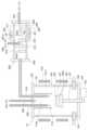
第1実施形態について、図面を参照しつつ説明する。まず、GaN層製造装置の構成について、図1を参照しつつ説明する。なお、図1に示されるGaN層製造装置は、図1の紙面上下方向を天地方向として設置され、種基板121上にGaN層122を成長させるものである。(First embodiment)
A first embodiment will be described with reference to the drawings. First, the configuration of the GaN layer manufacturing apparatus will be described with reference to FIG. The GaN layer manufacturing apparatus shown in FIG. 1 is installed with the vertical direction of the page of FIG.
図1に示されるように、GaN層製造装置は、GaN層122を成長させる成長装置10、およびGaN層122を成長させるための原料ガスとしての三塩化ガリウムガスを生成する生成装置20を備えている。また、GaN層製造装置は、GaN層122を成長させるための各種のガスを成長装置10へ供給する第1~第3供給配管310~330等を備えている。 As shown in FIG. 1, the GaN layer manufacturing apparatus includes a
成長装置10は、成長用容器100、加熱容器110、台座120、シャフト131、回転変位機構132、加熱装置140等を有している。 The
成長用容器100は、反応室を構成する中空部101aを備えた筒状の筒部101と、筒部101に備えられて中空部101aを閉塞する第1蓋部102および第2蓋部103とを有している。筒部101は、石英ガラス等で構成され、本実施形態では、円筒状とされている。第1蓋部102および第2蓋部103は、SUS等で構成されており、第1蓋部102が筒部101のうちの天側となる端部に備えられ、第2蓋部103が筒部101のうちの地側となる端部に備えられている。そして、成長用容器100は、GaN層122を成長させるための他の構成要素が中空部101a内に配置され、この中空部101aの圧力を真空引きすることによって減圧できる構造とされている。 The
また、成長用容器100には、GaN層122を成長させるための各種のガスを供給する第1~第3供給配管310~330が備えられている。本実施形態では、第1蓋部102に第1~第3供給配管310~330が備えられている。具体的には、第1蓋部102には、生成装置20で生成されたGaN層122を成長させるためのガリウム系ガスとして、三塩化ガリウムガスを成長用容器100内に供給する第1供給配管310が備えられている。第1蓋部102には、三塩化ガリウムガスと共にGaN層122を成長させるためのアンモニア系ガスとして、アンモニアガスを成長用容器100内に供給する第2供給配管320が備えられている。第1蓋部102には、キャリアガスとしての窒素ガスを成長用容器100内に供給する第3供給配管330が備えられている。なお、本実施形態では、後述するように、第1供給配管310に塩素ガスが供給され得る。このため、第1供給配管310は、例えば、耐腐食性を有するフッ素コーティングが施された配管で構成される。 The
そして、本実施形態の第1~第3供給配管310~330は、一端部が後述の加熱容器110内に位置するように配置されている。但し、第3供給配管330は、一端部が第1供給配管310および第2供給配管320の一端部よりも第1蓋部102側に位置するように配置されている。言い換えると、第1~第3供給配管310~330は、第1、第2供給配管310、320から供給されたガスが、第3供給配管330から供給されたガスによって下方(すなわち、後述の種基板121側)に流動し易くなるように、配置されている。 One end of each of the first to
なお、第1供給配管310は、成長装置10側の一端部と反対側の他端部側が生成装置20に備えられている。つまり、第1供給配管310は、成長装置10と生成装置20とを繋ぐように配置されている。また、第1供給配管310は、後述する生成用容器200よりもガスの流れ方向を法線方向とする断面積が小さくされている。そして、第2供給配管320および第3供給配管330は、特に図示しないが、成長装置10の一端部と反対側の他端部がそれぞれのガス供給源と接続されている。 The
さらに、成長用容器100には、GaN層122の成長に寄与しなかった未反応ガス等を含む排気ガスを排出する排出口104が備えられている。本実施形態では、成長用容器100のうちの第2蓋部103側の部分に排出口104が備えられている。 Furthermore, the
加熱容器110は、例えば、アルミナ、ジルコニア、熱分解炭素、黒鉛(グラファイト)等で構成されており、中空部110aを有する円筒状に形成されている。そして、加熱容器110は、第1~第3供給配管310~330からの各種のガスが中空部110a内に供給されるように、第1蓋部102に備えられている。 The
台座120は、GaN層122を成長させるためのGaNで構成される種基板121が配置される部材であり、加熱容器110よりも下方に配置されている。台座120は、熱エッチングされ難い材料で構成され、例えば、表面をPbN、SiC、TaCやNbC等の高融点金属炭化物にてコーティングした黒鉛等で構成されている。そして、この台座120のうち第1~第3供給配管310~330側に位置する一面120aに種基板121が貼り付けられ、種基板121の表面にGaN層122が成長させられる。 The
なお、本実施形態では、後述するように、種基板121上に三塩化ガリウムガスおよびアンモニアガスが供給されることでGaN層122が成長させられる。ここで、GaN層122を成長させる際に三塩化ガリウムガスを用いた場合、GaN層122は、種基板121の成長面が窒素面であると成長し易く、種基板121の成長面がガリウム面であると成長し難いことが報告されている。したがって、本実施形態では、種基板121は、GaN層122の成長面が窒素面となるようにして配置される。言い換えると、種基板121は、台座120と反対側の面が窒素面となるようにして配置される。 In this embodiment, as will be described later, the
また、台座120は、種基板121が配置される面と反対側の面にシャフト131が連結されている。そして、台座120は、シャフト131の回転に伴って回転させられると共に、シャフト131が成長用容器100の軸方向(すなわち、図1中紙面上下方向)に沿って変位することで共に変位する構成とされている。なお、シャフト131は、台座120と同様に、熱エッチングされ難い材料で構成され、例えば、表面をPbN、SiC、TaCやNbC等の高融点金属炭化物にてコーティングした黒鉛等で構成されている。 Moreover, the
回転変位機構132は、ギアやモータ等を含んで構成され、シャフト131と接続されてシャフト131を回転させると共にシャフト131を変位させる部材である。なお、回転変位機構132は、シャフト131を変位させる際には、GaN層122の成長に伴って当該GaN層122における成長表面の温度が成長に適した温度となるようにシャフト131(すなわち、種基板121)を変位させる。また、本実施形態の回転変位機構132は、GaN層122を成長させる際には、特に限定されるものではないが、台座120が1分間に200回転以上の回転となるようにシャフト131を回転させる。 The
加熱装置140は、加熱容器110や成長用容器100内を加熱するものであり、例えば、誘導加熱用コイルや直接加熱用コイル等の加熱コイルによって構成され、成長用容器100の周囲を囲むように配置されている。そして、本実施形態の加熱装置140は、GaN層122を成長させる際には、種基板121の周囲が1000~1300℃程度となり、加熱容器110内の温度が700℃以上となるように駆動される。 The
生成装置20は、生成用容器200および加熱装置240等を有している。生成用容器200は、中空部201aを有する筒状の筒部201と、筒部201に備えられて中空部201aを閉塞する第1蓋部202および第2蓋部203とを有している。筒部201は、石英ガラス等で構成され、本実施形態では、円筒状とされている。第1蓋部202および第2蓋部203は、SUS等で構成されている。第1蓋部202は、筒部201のうちの第1供給配管310が接続される側と反対側の端部に備えられ、第2蓋部203は、筒部201のうちの第1供給配管310が接続される側の端部に備えられている。なお、生成用容器200は、成長用容器100と同様に、中空部201aの圧力を真空引きすることによって減圧できる構造とされている。 The
生成用容器200には、中空部201aを、第1蓋部202側の第1空間211と、第2蓋部203側の第2空間212とに区画する区画壁213が備えられている。但し、この区画壁213は、第1空間211と第2空間212との連通が維持されるように形成されている。言い換えると、区画壁213は、第1空間211と第2空間212とを完全に区画しないように備えられている。 The
そして、第1空間211には、金属ガリウム220が配置されている。第2空間212には、本実施形態では、後述するように第1空間211で生成された一塩化ガリウムガスおよび塩素ガスと接触する壁面を増加させるための仕切壁214が備えられている。
また、生成用容器200には、塩素ガスを生成用容器200内に誘導する第1誘導配管231および第2誘導配管232が備えられている。本実施形態では、第1誘導配管231は、第1空間211に塩素ガスを誘導できるように、第1蓋部202に備えられている。第2誘導配管232は、第2空間212に塩素ガスを誘導できるように、筒部201に備えられている。なお、本実施形態では、第1誘導配管231および第2誘導配管232から生成用容器200内にキャリアガスとしての窒素ガスも誘導される。 In addition, the
加熱装置240は、生成用容器200内を加熱するものであり、例えば、抵抗加熱式ヒータ等で構成され、生成用容器200の周囲に配置されている。本実施形態では、加熱装置240は、生成用容器200のうちの第1空間211を構成する部分を囲むように配置される。そして、加熱装置240は、GaN層122を成長させる際には、第1空間211が800~900℃程度となり、第2空間212のうちの第2蓋部203側の温度が第1空間211からの伝熱によって150℃程度となるように、駆動される。なお、本実施形態の第2空間212は、第1空間211からの伝熱によって加熱されるため、第1空間211側の部分から第2蓋部203側に向かって温度が徐々に低くなる温度勾配となる。 The
そして、生成装置20には、第2蓋部203に第1供給配管310の他端部が備えられている。なお、特に図示しないが、第1供給配管310の周囲にも加熱装置が配置される。そして、第1供給配管310は、GaN層122を成長させる際には、例えば、150℃程度に加熱されるようになっている。 The generating
以上が本実施形態におけるGaN層製造装置の構成である。次に、上記GaN層製造装置を用いたGaN層122の製造方法について説明する。 The above is the configuration of the GaN layer manufacturing apparatus according to this embodiment. Next, a method for manufacturing the
まず、上記GaN層製造装置を用意し、台座120の一面120aに種基板121を配置する。本実施形態では、上記のように、GaN層122の成長面が窒素面となるように種基板121を配置する。そして、回転変位機構132により、シャフト131を介して台座120を回転させると共に、台座120の位置を調整する。なお、GaN層122を成長させている際には、GaN層122の成長レートに合せて台座の高さを調整する。これにより、GaN層の成長表面の高さがほぼ一定に保たれ、成長表面温度の温度分布を効果的に制御することが可能となる。 First, the GaN layer manufacturing apparatus is prepared, and the
次に、各加熱装置140、240を駆動する。具体的には、成長用容器100内に配置された種基板121の周囲が1000~1300℃程度となると共に加熱容器110内の温度が700℃以上となるように、加熱装置140を駆動する。また、生成用容器200における第1空間211が800~900℃程度となり、第2空間212のうちの第2蓋部203側の部分が150℃程度となるように加熱装置240を駆動する。さらに、図示を省略しているが、第1供給配管310も150℃程度なるように、これらの周囲に配置される加熱装置を駆動する。 Next, each
続いて、生成装置20内に、第1誘導配管231および第2誘導配管232から、塩素ガスおよびキャリアガスとしての窒素ガスを誘導する。これにより、第1空間211では、上記化学式1で示されるように、金属ガリウム220と塩素ガスとが反応し、一塩化ガリウムガスが生成される。また、この一塩化ガリウムガスが第2空間212に流動することにより、上記化学式2で示されるように、一塩化ガリウムガスが第2空間212に誘導されている塩素ガスと反応して三塩化ガリウムガスが生成される。そして、三塩化ガリウムガスが第1供給配管310を介して成長装置10に供給される。この場合、本実施形態の第2空間212には、仕切壁214が備えられている。このため、第2空間212に誘導されたガスは、高温部分としての仕切壁214に衝突し易くなると共に流動距離が長くなる。したがって、一塩化ガリウムガスが塩素ガスと反応されずに残存することを抑制できる。 Subsequently, chlorine gas and nitrogen gas as a carrier gas are guided into the
この際、本実施形態では、第2誘導配管232からは、第1空間211で生成された一塩化ガリウムの全てを三塩化ガリウムにするのに必要な量以上の塩素ガスを誘導する。例えば、第1誘導配管231から100sccmの塩素ガスを誘導した場合には、第2誘導配管232から200sccm以上の塩素ガスを誘導する。これにより、第2空間212で一塩化ガリウムガスが残存することを抑制できる。なお、第1誘導配管231および第2誘導配管232から誘導されるキャリアガスとしての窒素ガスは、例えば、1slm程度が誘導される。 At this time, in this embodiment, from the
そして、第2供給配管320からアンモニアガスを成長用容器100に供給すると共に、第3供給配管330から窒素ガスを成長用容器100に供給する。これにより、アンモニアガスおよび三塩化ガリウムガスが流動して種基板121に供給され、種基板121の表面にGaN層122が成長させられる。なお、アンモニアガスの供給は、加熱装置140を駆動した後であって、窒素抜けを防止するために、種基板121の周囲の温度が500℃以下である状態で開始することが好ましい。また、アンモニアガスは、例えば、1~5slm程度が供給される。キャリアガスとしての窒素ガスは、例えば、1~10slm程度が供給される。 Ammonia gas is supplied from the
以上説明した本実施形態によれば、生成装置20では、第2誘導配管232から、第1空間211で生成された一塩化ガリウムガスの全てを三塩化ガリウムガスにするのに必要な量以上の塩素ガスを誘導する。このため、一塩化ガリウムガスが残存することを抑制でき、一塩化ガリウムガスが固化して第1供給配管310が閉塞することを抑制できる。 According to the present embodiment described above, in the
(第2実施形態)
第2実施形態について説明する。本実施形態は、第1実施形態に対し、生成装置20に第3誘導配管を追加したものである。その他に関しては、第1実施形態と同様であるため、ここでは説明を省略する。(Second embodiment)
A second embodiment will be described. In this embodiment, a third guide pipe is added to the
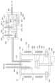
本実施形態では、図2に示されるように、生成装置20に第3誘導配管233が備えられている。具体的には、第3誘導配管233は、第2空間212に塩素ガスおよび窒素ガスを誘導できるように、筒部201に備えられている。より詳しくは、第3誘導配管233は、第2誘導配管232よりも第2蓋部203側に備えられており、生成装置20と第1供給配管310との連結部分の近傍に塩素ガスを誘導できるように配置されている。 In this embodiment, as shown in FIG. 2, the
以上が本実施形態におけるGaN層製造装置の構成である。次に、上記GaN層製造装置を用いたGaN層122の製造方法について説明する。 The above is the configuration of the GaN layer manufacturing apparatus according to this embodiment. Next, a method for manufacturing the
本実施形態では、生成装置20で三塩化ガリウムガスを生成する際、第3誘導配管233からも塩素ガスを誘導する。例えば、第1誘導配管231から100sccmの塩素ガスを誘導した場合には、第2誘導配管232から200sccm以上の塩素ガスを誘導し、第3誘導配管233から20sccm程度の塩素ガスを誘導する。これにより、第2空間212で一塩化ガリウムガスが残存することをさらに抑制できる。つまり、第1供給配管310に一塩化ガリウムガスが誘導されることをさらに抑制できる。 In the present embodiment, chlorine gas is also guided from the
以上説明した本実施形態によれば、生成装置20では、第2誘導配管232から一塩化ガリウムガスの全てを三塩化ガリウムガスにするのに必要な量以上の塩素ガスを誘導する。このため、上記第1実施形態と同様の効果を得ることができる。 According to the present embodiment described above, the
(1)本実施形態では、第3誘導配管233からも塩素ガスを誘導している。このため、一塩化ガリウムガスが第1供給配管310内に誘導されることをさらに抑制でき、第1供給配管310が閉塞することをさらに抑制できる。 (1) In this embodiment, chlorine gas is also guided from the
(第3実施形態)
第3実施形態について説明する。本実施形態は、第1実施形態に対し、成長装置10に第4供給配管を備えるものである。その他に関しては、第1実施形態と同様であるため、ここでは説明を省略する。(Third Embodiment)
A third embodiment will be described. This embodiment is different from the first embodiment in that the
まず、上記のようなGaN層製造装置では、生成装置20の第2空間212に誘導する塩素ガスを多量にすることにより、第1供給配管310が閉塞することを抑制できるようにしている。しかしながら、生成装置20の第2空間212に誘導する塩素ガスを多量にすることにより、生成装置20から成長装置10へ塩素ガスも供給され得る。この場合、塩素ガスがエッチングガスとして機能し、GaN層122がエッチングされる可能性がある。 First, in the GaN layer manufacturing apparatus as described above, a large amount of chlorine gas is guided to the
このため、本実施形態では、図3に示されるように、成長装置10に水素ガスを供給する第4供給配管340が備えられている。具体的には、第4供給配管340は、一端部が加熱容器110内に位置すると共に第3供給配管330とほぼ同じ位置となるように配置され、他端部が図示しないガス供給源と接続されている。 For this reason, in this embodiment, as shown in FIG. 3, a
以上が本実施形態におけるGaN層製造装置の構成である。次に、上記GaN層製造装置を用いたGaN層122の製造方法について説明する。 The above is the configuration of the GaN layer manufacturing apparatus according to this embodiment. Next, a method for manufacturing the
本実施形態では、GaN層122を成長させる際、第4供給配管340から成長装置10内に水素ガスを誘導する。これにより、第1供給配管310から供給され得る塩素ガスは、下記化学式4のように、水素ガスと反応し、塩素ガスよりエッチング性の弱い塩化水素ガスとなる。 In this embodiment, when growing the
(化4)1/2Cl2+H2→HCl
したがって、第1供給配管310(すなわち、生成装置20)から供給され得る塩素ガスによってGaN層122がエッチングされることを抑制できる。(Formula 4) 1/2Cl2 +H2 →HCl
Therefore, etching of the
なお、塩素ガスを水素ガスと反応させる場合には、周囲の温度が700℃以上となる部分で反応させることが好ましい。このため、本実施形態では、加熱容器110内の温度が700℃以上となるようにしている。また、第4供給配管340から供給される水素ガスは、例えば、第2誘導配管232から200sccmの塩素ガスを第2空間212に誘導した場合には、50~500sccm程度とされればよい。 When chlorine gas is reacted with hydrogen gas, it is preferable that the reaction be carried out in a portion where the ambient temperature is 700° C. or higher. Therefore, in this embodiment, the temperature inside the
さらに、成長装置10内に水素ガスを供給することにより、下記化学式5に示されるように、水素ガスは、第1供給配管310から供給される三塩化ガリウムガスとも反応して一塩化ガリウムガスを生成する。 Furthermore, by supplying hydrogen gas into the
(化5)GaCl3+H2→GaCl+2HCl
このため、本実施形態では、アンモニアガスおよび一塩化ガリウムガスが流動して種基板121に供給されることにより、下記化学式6に示されるように、種基板121の表面にGaN層122が成長させられる。(Formula 5) GaCl3 +H2 →GaCl+2HCl
Therefore, in the present embodiment, the ammonia gas and the gallium monochloride gas flow and are supplied to the
(化6)GaCl+NH3→GaN+HCl+H2
ここで、GaN層122を成長させる際に一塩化ガリウムガスを用いた場合、GaN層122は、種基板121の成長面が窒素面であってもガリウム面であっても成長し易いことが報告されている。したがって、本実施形態では、種基板121は、GaN層122の成長面として所望の面を選択することができる。(Chemical Formula 6) GaCl+NH3 →GaN+HCl+H2
Here, it is reported that when gallium monochloride gas is used to grow the
以上説明した本実施形態によれば、生成装置20では、第2誘導配管232から一塩化ガリウムガスの全てを三塩化ガリウムガスにするのに必要な量以上の塩素ガスを誘導する。このため、上記第1実施形態と同様の効果を得ることができる。 According to the present embodiment described above, the
(1)本実施形態では、成長装置10内へ水素ガスを供給している。このため、第1供給配管310から成長装置10内へ供給され得る塩素ガスがそのままGaN層122に達することを抑制でき、GaN層122がエッチングされることを抑制できる。また、第1供給配管310から成長装置10内へ供給される三塩化ガリウムガスが水素ガスと反応して一塩化ガリウムガスとなり、GaN層122は、一塩化ガリウムとアンモニアガスとの反応によって成長させられる。このため、GaN層122の成長面として所望の面を選択することができる。(1) In this embodiment, hydrogen gas is supplied into the
(他の実施形態)
本開示は、実施形態に準拠して記述されたが、本開示は当該実施形態や構造に限定されるものではないと理解される。本開示は、様々な変形例や均等範囲内の変形をも包含する。加えて、様々な組み合わせや形態、さらには、それらに一要素のみ、それ以上、あるいはそれ以下、を含む他の組み合わせや形態をも、本開示の範疇や思想範囲に入るものである。(Other embodiments)
Although the present disclosure has been described with reference to embodiments, it is understood that the present disclosure is not limited to such embodiments or structures. The present disclosure also includes various modifications and modifications within the equivalent range. In addition, various combinations and configurations, as well as other combinations and configurations, including single elements, more, or less, are within the scope and spirit of this disclosure.
上記各実施形態において、成長装置10の構成は適宜変更である。例えば、上記各実施形態では、台座120の回転および変位を行う回転変位機構132を備える例を説明したが、台座120の回転のみを行って変位を行わないようにしてもよい。また、排出口104は、成長用容器100における第1蓋部102側に配置されていてもよい。 In each of the embodiments described above, the configuration of the
また、上記各実施形態において、第2空間212に仕切壁214が備えられていなくてもよい。
そして、上記各実施形態を組み合わせることもできる。例えば、上記第2実施形態を上記第3実施形態に組み合わせ、第3誘導配管233を備えるようにしてもよい。Further, in each of the above embodiments, the
Further, each of the above embodiments can be combined. For example, the second embodiment described above may be combined with the third embodiment described above, and the
10 成長装置
20 生成装置
101a 中空部
100 成長用容器
120 台座
121 種基板
122 GaN層
211 第1空間
212 第2空間
220 金属ガリウム
231 第1誘導配管
232 第2誘導配管
310 供給配管REFERENCE SIGNS
Claims (4)
Translated fromJapanese反応室を構成する中空部(101a)で前記窒化ガリウム層が成長させられる筒状の成長用容器(100)を有する成長装置(10)と、
前記成長用容器の前記中空部内に配置され、前記窒化ガリウム層が成長させられる前記種基板が配置される台座(120)と、
前記ガリウム系ガスとしての三塩化ガリウムガスを生成する生成装置(20)と、
前記生成装置と前記成長装置とを繋ぎ、前記生成装置で生成された前記三塩化ガリウムガスを前記成長装置へ供給する供給配管(310)と、を備え、
前記生成装置は、金属ガリウム(220)が配置される第1空間(211)および前記第1空間と前記供給配管との間に位置する第2空間(212)と、前記第1空間に塩素ガスを誘導する第1誘導配管(231)と、前記第2空間に塩素ガスを誘導する第2誘導配管(232)と、を有し、
前記第2誘導配管は、前記第1誘導配管から前記塩素ガスが誘導されることで生成された一塩化ガリウムガスを前記三塩化ガリウムガスにするのに必要な塩素ガスの量よりも多い塩素ガスが誘導されるようになっている窒化ガリウム層製造装置。A gallium nitride layer manufacturing apparatus for growing a gallium nitride layer (122) by supplying a gallium-based gas and an ammonia-based gas onto a seed substrate (121) made of gallium nitride,
a growth apparatus (10) having a cylindrical growth container (100) in which the gallium nitride layer is grown in a hollow portion (101a) constituting a reaction chamber;
a pedestal (120) disposed within the hollow portion of the growth vessel and on which the seed substrate on which the gallium nitride layer is to be grown is disposed;
a generation device (20) for generating gallium trichloride gas as the gallium-based gas;
a supply pipe (310) connecting the generation device and the growth device and supplying the gallium trichloride gas generated in the generation device to the growth device;
The generator includes a first space (211) in which metal gallium (220) is placed, a second space (212) located between the first space and the supply pipe, and chlorine gas in the first space. and a second induction pipe (232) for guiding chlorine gas to the second space,
The second induction pipe is provided with chlorine gas in an amount larger than the amount of chlorine gas required to convert the gallium monochloride gas generated by guiding the chlorine gas from the first induction pipe into the gallium trichloride gas. gallium nitride layer manufacturing apparatus adapted to induce a
反応室を構成する中空部(101a)で前記窒化ガリウム層が成長させられる筒状の成長用容器(100)を有する成長装置(10)と、
前記成長用容器の前記中空部内に配置され、前記窒化ガリウム層が成長させられる前記種基板が配置される台座(120)と、
前記ガリウム系ガスとしての三塩化ガリウムガスを生成する生成装置(20)と、
前記生成装置と前記成長装置とを繋ぎ、前記生成装置で生成された前記三塩化ガリウムガスを前記成長装置へ供給する供給配管(310)と、を備え、
前記生成装置は、金属ガリウム(220)が配置される第1空間(211)および前記第1空間と前記供給配管との間に位置する第2空間(212)と、前記第1空間に塩素ガスを誘導する第1誘導配管(231)と、前記第2空間に塩素ガスを誘導する第2誘導配管(232)と、を有する窒化ガリウム層製造装置を用意することと、
前記生成装置で前記三塩化ガリウムガスを生成して前記窒化ガリウム層を成長させることと、を行い、
前記三塩化ガリウムガスを生成することでは、前記第1誘導配管から前記塩素ガスを誘導して前記金属ガリウムと前記塩素ガスを反応させて一塩化ガリウムガスを生成することと、前記第2誘導配管から前記塩素ガスを誘導し、前記一塩化ガリウムガスと前記塩素ガスとを反応させて前記三塩化ガリウムガスを生成することと、を行い、
前記第2誘導配管から前記塩素ガスを誘導することでは、前記一塩化ガリウムガスを前記三塩化ガリウムガスにするのに必要な塩素ガスの量よりも多い塩素ガスを誘導する窒化ガリウム層の製造方法。A gallium nitride layer manufacturing method for growing a gallium nitride layer (122) by supplying a gallium-based gas and an ammonia-based gas onto a seed substrate (121) made of gallium nitride, comprising:
a growth apparatus (10) having a cylindrical growth container (100) in which the gallium nitride layer is grown in a hollow portion (101a) constituting a reaction chamber;
a pedestal (120) disposed within the hollow portion of the growth vessel and on which the seed substrate on which the gallium nitride layer is to be grown is disposed;
a generation device (20) for generating gallium trichloride gas as the gallium-based gas;
a supply pipe (310) connecting the generation device and the growth device and supplying the gallium trichloride gas generated in the generation device to the growth device;
The generator includes a first space (211) in which metal gallium (220) is placed, a second space (212) located between the first space and the supply pipe, and chlorine gas in the first space. and a second guide pipe (232) for guiding chlorine gas into the second space;
growing the gallium nitride layer by generating the gallium trichloride gas in the generator;
In generating the gallium trichloride gas, the chlorine gas is guided from the first induction pipe to react the metal gallium and the chlorine gas to generate gallium monochloride gas; deriving the chlorine gas from and reacting the gallium monochloride gas with the chlorine gas to produce the gallium trichloride gas;
A method for producing a gallium nitride layer, wherein the chlorine gas is guided through the second induction pipe so that chlorine gas is introduced in an amount larger than the amount of chlorine gas required to convert the gallium monochloride gas into the gallium trichloride gas. .
Priority Applications (1)
| Application Number | Priority Date | Filing Date | Title |
|---|---|---|---|
| JP2021206095AJP2023091381A (en) | 2021-12-20 | 2021-12-20 | Apparatus and method for manufacturing gallium nitride layer |
Applications Claiming Priority (1)
| Application Number | Priority Date | Filing Date | Title |
|---|---|---|---|
| JP2021206095AJP2023091381A (en) | 2021-12-20 | 2021-12-20 | Apparatus and method for manufacturing gallium nitride layer |
Publications (1)
| Publication Number | Publication Date |
|---|---|
| JP2023091381Atrue JP2023091381A (en) | 2023-06-30 |
Family
ID=86941618
Family Applications (1)
| Application Number | Title | Priority Date | Filing Date |
|---|---|---|---|
| JP2021206095APendingJP2023091381A (en) | 2021-12-20 | 2021-12-20 | Apparatus and method for manufacturing gallium nitride layer |
Country Status (1)
| Country | Link |
|---|---|
| JP (1) | JP2023091381A (en) |
Citations (2)
| Publication number | Priority date | Publication date | Assignee | Title |
|---|---|---|---|---|
| WO2011142402A1 (en)* | 2010-05-12 | 2011-11-17 | 国立大学法人東京農工大学 | Method for producing gallium trichloride gas and method for producing nitride semiconductor crystal |
| WO2015037232A1 (en)* | 2013-09-11 | 2015-03-19 | 国立大学法人東京農工大学 | Nitride semiconductor crystal, manufacturing method, and manufacturing apparatus |
- 2021
- 2021-12-20JPJP2021206095Apatent/JP2023091381A/enactivePending
Patent Citations (2)
| Publication number | Priority date | Publication date | Assignee | Title |
|---|---|---|---|---|
| WO2011142402A1 (en)* | 2010-05-12 | 2011-11-17 | 国立大学法人東京農工大学 | Method for producing gallium trichloride gas and method for producing nitride semiconductor crystal |
| WO2015037232A1 (en)* | 2013-09-11 | 2015-03-19 | 国立大学法人東京農工大学 | Nitride semiconductor crystal, manufacturing method, and manufacturing apparatus |
Similar Documents
| Publication | Publication Date | Title |
|---|---|---|
| US8486192B2 (en) | Thermalizing gas injectors for generating increased precursor gas, material deposition systems including such injectors, and related methods | |
| JP6491484B2 (en) | Silicon carbide crystal growth by silicon chemical vapor transport | |
| JP2019087616A (en) | Nitride semiconductor manufacturing apparatus and manufacturing method | |
| CN103221586B (en) | The method forming block III-nitride material on metal nitride growth templates layer and the structure formed by described method | |
| JP2005223243A (en) | Group III nitride semiconductor crystal manufacturing method and hydride vapor phase growth apparatus | |
| JP2009500287A (en) | Method and reactor for crystal growth | |
| JP4900966B2 (en) | Method for producing gallium hydride gas and method for producing gallium nitride crystal | |
| JP2023091381A (en) | Apparatus and method for manufacturing gallium nitride layer | |
| JP2012080082A (en) | System and method for forming semiconductor material by atomic layer deposition | |
| JP2017178772A (en) | Method for producing group III nitride crystal | |
| JP7658192B2 (en) | Gallium nitride layer manufacturing apparatus and method for manufacturing gallium nitride layer | |
| TWI470113B (en) | Thermalizing gas injectors for generating increased precursor gas, material deposition systems including such injectors, and related methods | |
| JP2023004176A (en) | Gallium nitride layer manufacturing device and gallium nitride layer manufacturing method | |
| JP6948091B2 (en) | Vapor deposition equipment | |
| JP7228185B2 (en) | Method for producing group III nitride crystal | |
| US20050255245A1 (en) | Method and apparatus for the chemical vapor deposition of materials | |
| JP2014053477A (en) | Solid metal gas supply device | |
| JP5395102B2 (en) | Vapor growth equipment | |
| JP7728541B2 (en) | Gallium nitride layer manufacturing apparatus and method for manufacturing a gallium nitride layer | |
| JP7722826B2 (en) | Metal trihalide gas manufacturing method and semiconductor material gas manufacturing apparatus | |
| JP7391900B2 (en) | Semiconductor material gas reactor and gas reaction vessel | |
| JP2024053477A (en) | Gallium nitride wafer manufacturing equipment | |
| JPS60169563A (en) | Manufacture and device for telluride metal | |
| WO2019225697A1 (en) | Apparatus for manufacturing silicon nitride single crystal, and method for manufacturing silicon nitride single crystal | |
| JP2007039274A (en) | Gas phase growing apparatus, manufacturing method of group iii nitride semiconductor substrate, and group iii nitride semiconductor substrate |
Legal Events
| Date | Code | Title | Description |
|---|---|---|---|
| A621 | Written request for application examination | Free format text:JAPANESE INTERMEDIATE CODE: A621 Effective date:20240624 | |
| A521 | Request for written amendment filed | Free format text:JAPANESE INTERMEDIATE CODE: A523 Effective date:20240625 | |
| A977 | Report on retrieval | Free format text:JAPANESE INTERMEDIATE CODE: A971007 Effective date:20250326 | |
| A131 | Notification of reasons for refusal | Free format text:JAPANESE INTERMEDIATE CODE: A131 Effective date:20250507 | |
| A521 | Request for written amendment filed | Free format text:JAPANESE INTERMEDIATE CODE: A523 Effective date:20250703 |