JP2023083396A - Arrays for longitudinal delivery of tumor-treating fields to body - Google Patents
Arrays for longitudinal delivery of tumor-treating fields to bodyDownload PDFInfo
- Publication number
- JP2023083396A JP2023083396AJP2023065747AJP2023065747AJP2023083396AJP 2023083396 AJP2023083396 AJP 2023083396AJP 2023065747 AJP2023065747 AJP 2023065747AJP 2023065747 AJP2023065747 AJP 2023065747AJP 2023083396 AJP2023083396 AJP 2023083396A
- Authority
- JP
- Japan
- Prior art keywords
- electrodes
- subject
- electric field
- substrate
- arrays
- Prior art date
- Legal status (The legal status is an assumption and is not a legal conclusion. Google has not performed a legal analysis and makes no representation as to the accuracy of the status listed.)
- Granted
Links
Images


Classifications
- A—HUMAN NECESSITIES
- A61—MEDICAL OR VETERINARY SCIENCE; HYGIENE
- A61N—ELECTROTHERAPY; MAGNETOTHERAPY; RADIATION THERAPY; ULTRASOUND THERAPY
- A61N1/00—Electrotherapy; Circuits therefor
- A61N1/02—Details
- A61N1/04—Electrodes
- A61N1/0404—Electrodes for external use
- A61N1/0472—Structure-related aspects
- A61N1/0476—Array electrodes (including any electrode arrangement with more than one electrode for at least one of the polarities)
- A—HUMAN NECESSITIES
- A61—MEDICAL OR VETERINARY SCIENCE; HYGIENE
- A61K—PREPARATIONS FOR MEDICAL, DENTAL OR TOILETRY PURPOSES
- A61K41/00—Medicinal preparations obtained by treating materials with wave energy or particle radiation ; Therapies using these preparations
- A61K41/0052—Thermotherapy; Hyperthermia; Magnetic induction; Induction heating therapy
- A—HUMAN NECESSITIES
- A61—MEDICAL OR VETERINARY SCIENCE; HYGIENE
- A61N—ELECTROTHERAPY; MAGNETOTHERAPY; RADIATION THERAPY; ULTRASOUND THERAPY
- A61N1/00—Electrotherapy; Circuits therefor
- A61N1/02—Details
- A61N1/04—Electrodes
- A61N1/0404—Electrodes for external use
- A61N1/0408—Use-related aspects
- A61N1/0428—Specially adapted for iontophoresis, e.g. AC, DC or including drug reservoirs
- A61N1/0432—Anode and cathode
- A61N1/044—Shape of the electrode
- A—HUMAN NECESSITIES
- A61—MEDICAL OR VETERINARY SCIENCE; HYGIENE
- A61N—ELECTROTHERAPY; MAGNETOTHERAPY; RADIATION THERAPY; ULTRASOUND THERAPY
- A61N1/00—Electrotherapy; Circuits therefor
- A61N1/02—Details
- A61N1/04—Electrodes
- A61N1/0404—Electrodes for external use
- A61N1/0472—Structure-related aspects
- A61N1/0484—Garment electrodes worn by the patient
- A—HUMAN NECESSITIES
- A61—MEDICAL OR VETERINARY SCIENCE; HYGIENE
- A61N—ELECTROTHERAPY; MAGNETOTHERAPY; RADIATION THERAPY; ULTRASOUND THERAPY
- A61N1/00—Electrotherapy; Circuits therefor
- A61N1/02—Details
- A61N1/04—Electrodes
- A61N1/0404—Electrodes for external use
- A61N1/0472—Structure-related aspects
- A61N1/0492—Patch electrodes
- A—HUMAN NECESSITIES
- A61—MEDICAL OR VETERINARY SCIENCE; HYGIENE
- A61N—ELECTROTHERAPY; MAGNETOTHERAPY; RADIATION THERAPY; ULTRASOUND THERAPY
- A61N1/00—Electrotherapy; Circuits therefor
- A61N1/18—Applying electric currents by contact electrodes
- A61N1/32—Applying electric currents by contact electrodes alternating or intermittent currents
- A61N1/321—Electromedical belts
- A—HUMAN NECESSITIES
- A61—MEDICAL OR VETERINARY SCIENCE; HYGIENE
- A61N—ELECTROTHERAPY; MAGNETOTHERAPY; RADIATION THERAPY; ULTRASOUND THERAPY
- A61N1/00—Electrotherapy; Circuits therefor
- A61N1/18—Applying electric currents by contact electrodes
- A61N1/32—Applying electric currents by contact electrodes alternating or intermittent currents
- A61N1/36—Applying electric currents by contact electrodes alternating or intermittent currents for stimulation
- A61N1/36002—Cancer treatment, e.g. tumour
- A—HUMAN NECESSITIES
- A61—MEDICAL OR VETERINARY SCIENCE; HYGIENE
- A61N—ELECTROTHERAPY; MAGNETOTHERAPY; RADIATION THERAPY; ULTRASOUND THERAPY
- A61N1/00—Electrotherapy; Circuits therefor
- A61N1/40—Applying electric fields by inductive or capacitive coupling ; Applying radio-frequency signals
- A—HUMAN NECESSITIES
- A61—MEDICAL OR VETERINARY SCIENCE; HYGIENE
- A61B—DIAGNOSIS; SURGERY; IDENTIFICATION
- A61B18/00—Surgical instruments, devices or methods for transferring non-mechanical forms of energy to or from the body
- A61B2018/00053—Mechanical features of the instrument of device
- A61B2018/00059—Material properties
- A—HUMAN NECESSITIES
- A61—MEDICAL OR VETERINARY SCIENCE; HYGIENE
- A61B—DIAGNOSIS; SURGERY; IDENTIFICATION
- A61B18/00—Surgical instruments, devices or methods for transferring non-mechanical forms of energy to or from the body
- A61B2018/00636—Sensing and controlling the application of energy
Landscapes
- Health & Medical Sciences (AREA)
- General Health & Medical Sciences (AREA)
- Veterinary Medicine (AREA)
- Public Health (AREA)
- Life Sciences & Earth Sciences (AREA)
- Animal Behavior & Ethology (AREA)
- Engineering & Computer Science (AREA)
- Radiology & Medical Imaging (AREA)
- Nuclear Medicine, Radiotherapy & Molecular Imaging (AREA)
- Biomedical Technology (AREA)
- Chemical & Material Sciences (AREA)
- Medicinal Chemistry (AREA)
- Pharmacology & Pharmacy (AREA)
- Epidemiology (AREA)
- Bioinformatics & Cheminformatics (AREA)
- Hospice & Palliative Care (AREA)
- Oncology (AREA)
- Electrotherapy Devices (AREA)
Abstract
Translated fromJapaneseDescription
Translated fromJapanese 「関連出願との相互参照」
本出願は、その全体が参照により本明細書に組み入れられる、2016年6月30日に出願された米国仮特許出願第62/356,986号の利益を主張する。"Cross Reference to Related Applications"
This application claims the benefit of US Provisional Patent Application No. 62/356,986, filed June 30, 2016, which is incorporated herein by reference in its entirety.
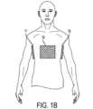
腫瘍治療電場(TTFields)は、細胞分裂を中断することにより硬化腫瘍を標的とする中間周波数範囲(例えば、125~250kHz、または場合によっては100~500kHz)の低強度交流電場(例えば、1~3V/cm)である。腫瘍治療電場は、通常、2組の電極アレイを介して伝達される。これらの組の各々を構成する電極アレイは、治療されている身体部分の両側に配置されている。図1Aおよび図1Bは、それぞれ対象者の頭および胸部における電極アレイの従来の配置を示す。これらの例のそれぞれにおいて、電極アレイの第1の組は、前方位置16/19に1つの電極アレイと後方位置(図示しないが、対応する前方位置のすぐ後ろに位置する)に第2の電極アレイを含む。AC電圧が前方電極アレイと後方電極アレイとの間に印加されると、結果として生じる電場の力線は、概して、対象物の正面と背面との間を延びるであろう。 Tumor therapeutic fields (TTFields) are low-intensity alternating electric fields (e.g., 1-3 V) in the intermediate frequency range (e.g., 125-250 kHz, or occasionally 100-500 kHz) that target hardened tumors by interrupting cell division. / cm). Tumor treatment fields are typically delivered through two sets of electrode arrays. The electrode arrays that make up each of these sets are positioned on either side of the body part being treated. 1A and 1B show conventional placement of electrode arrays on a subject's head and chest, respectively. In each of these examples, the first set of electrode arrays has one electrode array in the
図1Aの例および図1Bの例のそれぞれは、右側位置14/17の第1の電極アレイと左側位置15/18の第2の電極アレイとを含む第2の組の電極アレイを含む。AC電圧が右側のアレイと左側のアレイとの間に印加されると、結果として生じる電場の力線は、概して、対象物の左側と右側との間を延びることになる。交流電圧は、(i)前後(A/P)電極アレイと(ii)右左(R/L)電極アレイとの間で交互の順序で印加され、それによって、電場の方向が上記の2つの方向の間で(例えば、1秒毎に)繰り返し切り替わる。 Each of the FIG. 1A and FIG. 1B examples includes a second set of electrode arrays including a first electrode array at
A/PおよびR/L電極アレイは、対象者の身体の多くの部分に2つのほぼ垂直な方向に電場を印加するのに非常に適しているが、A/PおよびR/L電極の使用が困難または不可能であり得るいくつかの状況が想定され得る。例としては、対象が電極アレイを配置するために一般的に使用される部位の1つに痛みまたは潰瘍を有する、並びに、A/PおよびR/L電極の両方を使用することが不快であるおよび/または実用的ではない(例えば、対象者の首、肘、膝など)。 Although A/P and R/L electrode arrays are well suited for applying electric fields in two nearly perpendicular directions to many parts of a subject's body, the use of A/P and R/L electrodes Some situations can be envisioned in which it may be difficult or impossible to Examples include: the subject has pain or an ulcer at one of the sites commonly used to place electrode arrays, and is uncomfortable using both A/P and R/L electrodes and/or impractical (eg, the subject's neck, elbows, knees, etc.).
本発明の一態様は、腫瘍治療電場を用いて対象者の身体内の標的領域を治療するための第1の装置を対象とし、標的領域は、長手方向軸を有する対象者の身体の一部に位置する。この装置は、1つ以上の静電容量結合電極の第1のセットと、1つ以上の電極の第1のセットを対象者の身体に対して保持するように構成された第1の基板とを含んでなり、1つ以上の電極の第1のセットが、標的領域の長手方向の前の位置で、対象者の身体の第1の部分を囲む。この装置はまた、1つ以上の静電容量結合電極の第2のセットと、1つ以上の電極の第2のセットを対象者の身体に対して保持するように構成された第2の基板とを含んでなり、1つ以上の電極の第2のセットが、標的領域の長手方向の次の位置で、対象者の身体の第2の部分を囲む。この装置はまた、1つ以上の静電容量結合電極の第3のセットと、第3の基板とを含んでなり、1つ以上の電極の第1のセットと1つ以上の電極の第2のセットとの間の長手方向の位置で、1つ以上の電極の第3のセットを対象者の身体に対して標的領域の第1の側に保持するように構成されている。この装置はまた、1つ以上の静電容量結合電極の第4のセットと、第4の基板とを含んでなり、1つ以上の電極の第1のセットと1つ以上の電極の第2のセットとの間の長手方向の位置で、1つ以上の電極の第4のセットを対象者の身体に対して標的領域の第1の側の反対の第2の側に保持するように構成されている。 One aspect of the present invention is directed to a first apparatus for treating a target region within a subject's body with a tumor treatment electric field, the target region being a portion of the subject's body having a longitudinal axis. Located in The device includes a first set of one or more capacitively coupled electrodes and a first substrate configured to hold the first set of one or more electrodes against the body of the subject. wherein a first set of one or more electrodes surrounds a first portion of the subject's body at a location longitudinally in front of the target area. The device also includes a second set of one or more capacitively coupled electrodes and a second substrate configured to hold the second set of one or more electrodes against the subject's body. and wherein a second set of one or more electrodes surrounds a second portion of the subject's body at a location longitudinally next to the target region. The device also comprises a third set of one or more capacitively coupled electrodes and a third substrate, wherein the first set of one or more electrodes and the second set of one or more electrodes A third set of one or more electrodes is configured to hold a third set of one or more electrodes on the first side of the target area relative to the subject's body at a longitudinal position between the sets of . The device also comprises a fourth set of one or more capacitively coupled electrodes and a fourth substrate, wherein the first set of one or more electrodes and the second set of one or more electrodes configured to hold a fourth set of one or more electrodes on a second side of the target area opposite the first side with respect to the subject's body at a longitudinal position between the sets of It is
第1の装置のいくつかの実施形態は、次から次へと繰り返し交互に、(a)1つ以上の電極の第1のセットと1つ以上の電極の第2のセットとの間に100~500kHzの周波数を有するAC電圧と、(b)1つ以上の電極の第3のセットと1つ以上の電極の第4のセットのとの間に100~500kHzの周波数を有するAC電圧と、を発生するように構成されたAC電圧発生器をさらに含んでなる。 Some embodiments of the first device repeatedly and alternately include: (a) 100 between the first set of one or more electrodes and the second set of one or more electrodes; (b) an AC voltage having a frequency of 100-500 kHz between the third set of one or more electrodes and the fourth set of one or more electrodes; further comprising an AC voltage generator configured to generate a
第1の装置のいくつかの実施形態は、次から次へと繰り返し交互に、(a)1つ以上の電極の第1のセットと1つ以上の電極の第2のセットとの間に125~250kHzの周波数を有するAC電圧と、(b)1つ以上の電極の第3のセットと1つ以上の電極の第4のセットのとの間に125~250kHzの周波数を有するAC電圧と、を発生するように構成されたAC電圧発生器をさらに含んでなる。 Some embodiments of the first device repeatedly and alternately include: (a) 125 between the first set of one or more electrodes and the second set of one or more electrodes; (b) an AC voltage having a frequency of 125-250 kHz between the third set of one or more electrodes and the fourth set of one or more electrodes; further comprising an AC voltage generator configured to generate a
第1の装置のいくつかの実施形態では、1つ以上の電極の第1のセットは第1の複数フラット電極要素を含み、1つ以上の電極の第2のセットは第2の複数フラット電極要素を含む。これらの実施形態のいくつかでは、第1の基板および第2の基板のそれぞれは可撓性である。 In some embodiments of the first device, the first set of one or more electrodes comprises a first multi-flat electrode element and the second set of one or more electrodes comprises a second multi-flat electrode element. contains elements. In some of these embodiments, each of the first substrate and the second substrate are flexible.
第1の装置のいくつかの実施形態では、第1および第2の基板のそれぞれは、対象者の胴体の周りにフィットするような形状および寸法である。第1の装置のいくつかの実施形態では、第1の基板は対象者の胴体の周りにフィットするような形状および寸法で、第2の基板は対象者の首の周りにフィットするような形状および寸法である。第1の装置のいくつかの実施形態では、第1の基板は対象者の首の周りにフィットするような形状および寸法で、第2の基板は対象者の頭の周りにフィットするような形状および寸法である。第1の装置のいくつかの実施形態では、第1の基板は対象者の首の周りにフィットするような形状および寸法で、第2の基板は対象者の頭にフィットするような形状および寸法である。第1の装置のいくつかの実施形態では、第1および第2の基板のそれぞれは対象者のリムの周りにフィットするような形状および寸法である。 In some embodiments of the first device, each of the first and second substrates is shaped and dimensioned to fit around the subject's torso. In some embodiments of the first device, the first substrate is shaped and dimensioned to fit around the subject's torso and the second substrate is shaped to fit around the subject's neck. and dimensions. In some embodiments of the first device, the first substrate is shaped and dimensioned to fit around the subject's neck and the second substrate is shaped to fit around the subject's head. and dimensions. In some embodiments of the first device, the first substrate is shaped and dimensioned to fit around the subject's neck and the second substrate is shaped and dimensioned to fit the subject's head. is. In some embodiments of the first device, each of the first and second substrates is shaped and dimensioned to fit around the rim of the subject.
第1の装置のいくつかの実施形態は、1つ以上の静電容量結合電極の第5のセットと、第5の基板とを含んでなり、1つ以上の電極の第1のセットと1つ以上の電極の第2のセットとの間の長手方向の位置で、1つ以上の電極の第5のセットを対象者の身体に対して標的領域の第3の側に保持するように構成されている。これらの実施形態はまた、1つ以上の静電容量結合電極の第6のセットと、第6の基板とを含んでなり、1つ以上の電極の第1のセットと1つ以上の電極の第2のセットとの間の長手方向の位置で、1つ以上の電極の第6のセットを対象者の身体に対して標的領域の第3の側の反対の第4の側に保持するように構成されている。 Some embodiments of the first apparatus comprise a fifth set of one or more capacitively coupled electrodes and a fifth substrate, wherein the first set of one or more electrodes and one configured to retain a fifth set of one or more electrodes on a third side of the target area relative to the subject's body at a longitudinal position between the second set of one or more electrodes; It is These embodiments also comprise a sixth set of one or more capacitively coupled electrodes and a sixth substrate, wherein the first set of one or more electrodes and the one or more electrodes longitudinally between the second set to hold a sixth set of one or more electrodes on a fourth side of the target area opposite the third side relative to the subject's body; is configured to
本発明の別の態様は、腫瘍治療電場を用いて対象者の身体内の標的領域を治療する第1の方法を対象とし、標的領域は、長手方向軸を有する対象者の身体の一部に位置する。この方法は、標的領域の長手方向の前の位置で対象者の身体の第1の部分を囲むように、1つ以上の電極の第1のセットを対象者の身体に取り付けることを含み、標的領域の長手方向に続く位置で対象者の身体の第2の部分を囲むように、1つ以上の電極の第2のセットを対象者の身体に取り付けることを含む。この方法はまた、1つ以上の電極の第1のセットと1つ以上の電極の第2のセットとの間に100~500kHzの周波数の第1のAC電圧を印加することを含み、標的領域を長手方向に通過する電場線を有する第1のAC電場を印加し、第1のAC電場は、標的領域の少なくとも一部において少なくとも1V/cmの電場強度を有する。 Another aspect of the invention is directed to a first method of treating a target region within a subject's body with a tumor-treating electric field, the target region being a portion of the subject's body having a longitudinal axis. To position. The method includes attaching a first set of one or more electrodes to the subject's body so as to surround a first portion of the subject's body at a position longitudinally in front of the target region; Attaching a second set of one or more electrodes to the subject's body to surround a second portion of the subject's body at a position longitudinally following the region. The method also includes applying a first AC voltage at a frequency of 100-500 kHz between the first set of one or more electrodes and the second set of one or more electrodes; is applied, the first AC electric field having electric field strengths of at least 1 V/cm over at least a portion of the target region.
第1の方法のいくつかの実施形態では、1つ以上の電極の第1および第2のセットのそれぞれは対象者の身体に静電容量結合されている。 In some embodiments of the first method, each of the first and second sets of one or more electrodes are capacitively coupled to the subject's body.
第1の方法のいくつかの実施形態は、1つ以上の電極の第1のセットと1つ以上の電極の第2のセットとの間の長手方向の位置で、標的領域の第1の側に、対象者の身体に1つ以上の電極の第3のセットを取り付けることを含み、さらに、1つ以上の電極の第1のセットと1つ以上の電極の第2のセットとの間の長手方向の位置で、標的領域の第1の側の反対側である第2の側に、対象者の身体に1つ以上の電極の第4のセットを取り付けることをさらに含む。これらの方法はまた、1つ以上の電極の第3のセットと1つ以上の電極の第4のセットとの間に100~500kHzの周波数の第1のAC電圧を印加することを含み、標的領域を通過する第2のAC電場を印加し、第2のAC電場は、標的領域の少なくとも一部において少なくとも1V/cmの電場強度を有する。これらの実施形態のいくつかでは、1つ以上の電極の第1、第2、第3、および第4のセットのそれぞれは、対象者の身体に静電容量結合されている。これらの実施形態のいくつかでは、第1および第2のAC電圧のそれぞれは、125~250kHzの周波数を有する。これらの実施形態のいくつかでは、第1のAC電圧を印加する工程および第2のAC電圧を印加する工程は、交互の順序で少なくとも10,000回繰り返される。 Some embodiments of the first method include the addition of a first side of the target area at a longitudinal position between the first set of one or more electrodes and the second set of one or more electrodes. , including attaching a third set of one or more electrodes to the subject's body, and further between the first set of one or more electrodes and the second set of one or more electrodes. Further comprising attaching a fourth set of one or more electrodes to the subject's body at a longitudinal position and on a second side opposite the first side of the target area. The methods also include applying a first AC voltage at a frequency of 100-500 kHz between a third set of one or more electrodes and a fourth set of one or more electrodes; A second AC electric field is applied through the region, the second AC electric field having an electric field strength of at least 1 V/cm over at least a portion of the target region. In some of these embodiments, each of the first, second, third, and fourth sets of one or more electrodes are capacitively coupled to the subject's body. In some of these embodiments, each of the first and second AC voltages has a frequency of 125-250 kHz. In some of these embodiments, the steps of applying the first AC voltage and applying the second AC voltage are repeated in alternating order at least 10,000 times.
第1の方法のいくつかの実施形態は、1つ以上の電極の第1のセットと1つ以上の電極の第2のセットとの間の長手方向の位置で、標的領域の第3の側に、対象者の身体に1つ以上の電極の第5のセットを取り付けることを含み、さらに、1つ以上の電極の第1のセットと1つ以上の電極の第2のセットとの間の長手方向の位置で、標的領域の第3の側の反対側である第4の側に、対象者の身体に1つ以上の電極の第6のセットを取り付けることをさらに含む。これらの方法はまた、1つ以上の電極の第5のセットと1つ以上の電極の第6のセットとの間に100~500kHzの周波数の第3のAC電圧を印加することを含み、標的領域を長手方向に通過する力線を有する第3のAC電場を印加し、第3のAC電場は、標的領域の少なくとも一部において少なくとも1V/cmの電場強度を有する。これらの実施形態のいくつかでは、第1のAC電圧を印加するステップ、第2のAC電圧を印加するステップ、および第3のAC電圧を印加する工程は、交互の順序で少なくとも10,000回繰り返される。 Some embodiments of the first method include applying a third side of the target area at a longitudinal position between the first set of one or more electrodes and the second set of one or more electrodes. , including attaching a fifth set of one or more electrodes to the subject's body, and further between the first set of one or more electrodes and the second set of one or more electrodes. Further comprising attaching a sixth set of one or more electrodes to the subject's body at a longitudinal position on a fourth side opposite the third side of the target area. The methods also include applying a third AC voltage at a frequency of 100-500 kHz between the fifth set of one or more electrodes and the sixth set of one or more electrodes; A third AC electric field is applied having lines of force passing longitudinally through the region, the third AC electric field having an electric field strength of at least 1 V/cm in at least a portion of the target region. In some of these embodiments, the steps of applying the first AC voltage, applying the second AC voltage, and applying the third AC voltage are performed in an alternating sequence at least 10,000 times. Repeated.
第1の方法のいくつかの実施形態では、1つ以上の電極の第1のセットは対象者の身体の第1の部分の周りに分布する第1の複数のフラット電極要素を含み、1つ以上の電極の第2のセットは対象者の身体の第2の部分の周りに分布する第2の複数のフラット電極要素を含む。 In some embodiments of the first method, the first set of one or more electrodes comprises a first plurality of flat electrode elements distributed about the first portion of the subject's body, and one A second set of such electrodes includes a second plurality of flat electrode elements distributed about a second portion of the subject's body.
第1の方法のいくつかの実施形態では、標的領域は対象者の胴体内に配置され、1つ以上の電極の第1のセットは標的領域の下の対象胴体の周りに配置され、1つ以上の電極の第2のセットは標的領域の上の対象胴体の周りに配置される。 In some embodiments of the first method, the target area is positioned within the subject's torso, the first set of one or more electrodes is positioned around the subject's torso below the target area, and one A second set of such electrodes is placed around the subject's torso over the target area.
第1の方法のいくつかの実施形態では、標的領域は対象者の胴体内に配置され、1つ以上の電極の第1のセットは標的領域の下の対象胴体の周りに配置され、1つ以上の電極の第2のセットは対象者の首の周りに配置される。 In some embodiments of the first method, the target area is positioned within the subject's torso, the first set of one or more electrodes is positioned around the subject's torso below the target area, and one A second set of such electrodes is placed around the subject's neck.
第1の方法のいくつかの実施形態では、標的領域は対象者の頭部中に配置され、1つ以上の電極の第1のセットは対象者の首の周りに配置され、1つ以上の電極の第2のセットは対象者の頭部の周りに配置される。 In some embodiments of the first method, the target region is positioned in the subject's head, the first set of one or more electrodes is positioned around the subject's neck, and one or more A second set of electrodes is placed around the subject's head.
第1の方法のいくつかの実施形態では、標的領域は対象者のリムに位置する。これらの実施形態では、長手方向軸はリムを通って近位から遠位方向に延び、1つ以上の電極の第1のセットは、標的領域に近い位置でリムの周りに配置され、1つ以上の電極の第2のセットは、標的領域に遠い位置でリムの周りに配置される。 In some embodiments of the first method, the target area is located in the subject's rim. In these embodiments, the longitudinal axis extends proximally to distally through the rim, and a first set of one or more electrodes are positioned about the rim at a location near the target area, one A second set of such electrodes is placed around the rim at a location remote from the target area.
本発明の別の態様は、腫瘍治療電場を用いて対象者の身体のリムにおける標的領域を治療するための第2の装置に関する。この装置は、1つ以上の静電容量結合電極の第1のセットと、1つ以上の電極の第1のセットが標的領域に近い位置でリムの第1の側を部分的に取り囲むように、対象者の身体に対して、1つ以上の電極の第1のセットを保持するように構成される第1の基板とを含んでなる。この装置はまた、1つ以上の静電容量結合電極の第2のセットと、1つ以上の電極の第2のセットが標的領域に遠い位置でリムの第2の側を部分的に取り囲むように、対象者の身体に対して、1つ以上の電極の第2のセットを保持するように構成される第2の基板とを含んでなる。リムの第2の側はリムの第1の側と反対である。この装置はまた、1つ以上の静電容量結合電極の第3のセットと、1つ以上の電極の第3のセットが標的領域に近い位置でリムの第2の側を部分的に取り囲むように、対象者の身体に対して、1つ以上の電極の第3のセットを保持するように構成される第3の基板とを含んでなる。この装置はまた、1つ以上の静電容量結合電極の第4のセットと、1つ以上の電極の第4のセットが標的領域に遠い位置でリムの第1の側を部分的に取り囲むように、対象者の身体に対して、1つ以上の電極の第4のセットを保持するように構成される第4の基板とを含んでなる。 Another aspect of the invention relates to a second apparatus for treating a target area in a limb of a subject's body with a tumor treatment electric field. The device includes a first set of one or more capacitively coupled electrodes such that the first set of one or more electrodes partially surrounds a first side of the rim at a location near the target area. , and a first substrate configured to hold a first set of one or more electrodes against the subject's body. The device also includes a second set of one or more capacitively coupled electrodes and such that the second set of one or more electrodes partially surrounds a second side of the rim at a location distal to the target area. and a second substrate configured to hold a second set of one or more electrodes against the subject's body. The second side of the rim is opposite the first side of the rim. The device also includes a third set of one or more capacitively coupled electrodes and such that the third set of one or more electrodes partially surrounds the second side of the rim at a location near the target area. and a third substrate configured to hold a third set of one or more electrodes against the subject's body. The device also includes a fourth set of one or more capacitively coupled electrodes and such that the fourth set of one or more electrodes partially surrounds the first side of the rim at a location distal to the target area. and a fourth substrate configured to hold a fourth set of one or more electrodes against the subject's body.
第2の装置のいくつかの実施形態は、次から次へと繰り返し交互に、(a)1つ以上の電極の第1のセットと1つ以上の電極の第2のセットとの間に100~500kHzの周波数を有する第1のAC電圧と、(b)1つ以上の電極の第3のセットと1つ以上の電極の第4のセットのとの間に100~500kHzの周波数を有する第2のAC電圧と、を発生するように構成されたAC電圧発生器をさらに含んでなる。これらの実施形態のいくつかでは、第1および第2のAC電圧のそれぞれは、125~250kHzの周波数を有する。 Some embodiments of the second device repeatedly and alternately include: (a) 100 between the first set of one or more electrodes and the second set of one or more electrodes; (b) a first AC voltage having a frequency of ∼500 kHz; 2 AC voltages, and an AC voltage generator configured to generate: In some of these embodiments, each of the first and second AC voltages has a frequency of 125-250 kHz.
第2の装置のいくつかの実施形態では、1つ以上の電極の第1、第2、第3、および第4のセットのそれぞれは、複数のフラット電極要素を含む。これらの実施形態のいくつかでは、第1、第2、第3、および第4の基板のそれぞれは可撓性である。 In some embodiments of the second device, each of the first, second, third and fourth sets of one or more electrodes comprises a plurality of flat electrode elements. In some of these embodiments, each of the first, second, third and fourth substrates is flexible.
第2の装置のいくつかの実施形態では、リムは腕で、第1および第3の基板のそれぞれは、肘に対して近位側で腕にフィットするような形状および寸法で、第2および第4の基板のそれぞれは、肘に対して遠位側で腕にフィットするような形状および寸法である。第2の装置のいくつかの実施形態では、リムは脚で、第1および第3の基板のそれぞれは、膝に対して近位側で脚にフィットするような形状および寸法で、第2および第4の基板のそれぞれは、膝に対して遠位側で脚にフィットするような形状および寸法である。 In some embodiments of the second device, the limb is the arm, each of the first and third substrates is shaped and dimensioned to fit the arm proximal to the elbow, the second and Each of the fourth substrates is shaped and dimensioned to fit the arm distal to the elbow. In some embodiments of the second device, the limb is the leg, each of the first and third substrates is shaped and dimensioned to fit the leg proximal to the knee, the second and Each of the fourth substrates is shaped and dimensioned to fit the leg distal to the knee.
本発明の別の態様は、腫瘍治療電場を用いて対象者の身体のリムの中の標的領域を治療する第2の方法に関する。この方法は、標的領域に近い位置でリムの第1の側を部分的に囲むように1つ以上の電極の第1のセットを取り付けることと、標的領域に遠い位置でリムの第2の側を部分的に囲むように1つ以上の電極の第2のセットを取り付けることとを含み、リムの第2の側はリムの第1の側の反対側である。この方法はまた、標的領域に近い位置でリムの第2の側を部分的に囲むように1つ以上の電極の第3のセットを取り付けることと、標的領域に遠い位置でリムの第1の側を部分的に囲むように1つ以上の電極の第4のセットを取り付けることとを含む。この方法はまた、1つ以上の電極の第1のセットと1つ以上の電極の第2のセットとの間に100~500kHzの周波数の第1のAC電圧を印加するステップであって、標的領域を通して第1のAC電場を印加し、第1のAC電場が、標的領域の少なくとも一部において少なくとも1V/cmの電場強度を有するように印加するステップを含み、さらに、1つ以上の電極の第3のセットと1つ以上の電極の第4のセットとの間に100~500kHzの周波数の第2のAC電圧を印加するステップであって、標的領域を通して第2のAC電場を印加し、第2のAC電場が、標的領域の少なくとも一部において少なくとも1V/cmの電場強度を有するように印加するステップを含む。この方法では、第1のAC電圧を印加するステップと第2のAC電圧を印加するステップとは、次から次へと繰り返し交互に実行される。 Another aspect of the invention relates to a second method of treating a target region within a limb of a subject's body using a tumor treatment electric field. The method includes attaching a first set of one or more electrodes to partially surround a first side of the rim near the target area and a second side of the rim farther from the target area. mounting a second set of one or more electrodes to partially surround the rim, the second side of the rim being opposite the first side of the rim. The method also includes attaching a third set of one or more electrodes to partially surround a second side of the rim at a location proximate to the target area; attaching a fourth set of one or more electrodes to partially surround the sides. The method also includes applying a first AC voltage at a frequency of 100-500 kHz between the first set of one or more electrodes and the second set of one or more electrodes, wherein the target applying a first AC electric field through the region, applying the first AC electric field such that the first AC electric field has an electric field strength of at least 1 V/cm in at least a portion of the target region; applying a second AC voltage at a frequency of 100-500 kHz between the third set and the fourth set of one or more electrodes, applying the second AC electric field through the target region; Applying a second AC electric field having an electric field strength of at least 1 V/cm over at least a portion of the target area. In this method, the steps of applying the first AC voltage and applying the second AC voltage are repeatedly alternated one after the other.
第2の方法のいくつかの実施形態では、1つ以上の電極の第1、第2、第3、および第4のセットのそれぞれは、対象者の身体に静電容量結合されている。これらの実施形態のいくつかでは、第1および第2のAC電圧のそれぞれは、125~250kHzの周波数を有する。 In some embodiments of the second method, each of the first, second, third, and fourth sets of one or more electrodes are capacitively coupled to the subject's body. In some of these embodiments, each of the first and second AC voltages has a frequency of 125-250 kHz.
第2の方法のいくつかの実施形態では、第1のAC電圧を印加するステップおよび第2のAC電圧を印加するステップは、交互の順序で少なくとも10,000回繰り返される。 In some embodiments of the second method, the steps of applying the first AC voltage and applying the second AC voltage are repeated at least 10,000 times in an alternating sequence.
第2の方法のいくつかの実施形態では、リムは腕で、1つ以上の電極の第1のセットおよび1つ以上の電極の第3のセットは、肘に対して近位に配置され、1つ以上の電極の第2のセットおよび1つ以上の電極の第4のセットは、肘に対して遠位に配置される。第2の方法のいくつかの実施形態では、リムは脚で、1つ以上の電極の第1のセットおよび1つ以上の電極の第3のセットは、膝に対して近位に配置され、1つ以上の電極の第2のセットおよび1つ以上の電極の第4のセットは、膝に対して遠位に配置される。 In some embodiments of the second method, the limb is an arm and the first set of one or more electrodes and the third set of one or more electrodes are positioned proximal to the elbow; A second set of one or more electrodes and a fourth set of one or more electrodes are positioned distal to the elbow. In some embodiments of the second method, the limb is the leg, the first set of one or more electrodes and the third set of one or more electrodes are positioned proximal to the knee; A second set of one or more electrodes and a fourth set of one or more electrodes are positioned distal to the knee.
第2の方法のいくつかの実施形態では、1つ以上の電極の第1、第2、第3、および第4のセットのそれぞれは、複数のフラット電極要素を含む。 In some embodiments of the second method, each of the first, second, third and fourth sets of one or more electrodes comprises a plurality of flat electrode elements.
様々な実施形態は、添付の図面を参照して以下に詳細に説明され、図中、類似の参照番号は類似の要素を表す。 Various embodiments are described in detail below with reference to the accompanying drawings, in which like reference numerals denote like elements.
以下に記載される実施形態は、標的領域内に長手方向の電場を生成するように構成された少なくとも一対の電極アレイを含むことによって、A/PおよびR/L電極を使用することの前述した制限を克服する。本明細書で使用されるように、以下のことに留意されたい。(1)身体の頭部および主要部分に関して、長手方向軸は前後方向軸および横方向軸の両方に対して垂直である。(2)脚または腕に関して、長手方向軸は近遠位方向軸である。(3)「長手方向電場」という用語は、長手方向軸とほぼ同じ方向に延びる電場を指し、長手方向軸と正確に平行である電場に限定されない。(4)長手方向電場を生成するように設計された電極アレイは「長手方向アレイ」と呼ばれる。(5)一般に対象者の左右の間、或いは、対象者の前後の間を延びる電場を発生させるように設計された従来の電極アレイは「緯度方向アレイ」と呼ばれる。 The embodiments described below demonstrate the use of A/P and R/L electrodes previously described by including at least one pair of electrode arrays configured to generate a longitudinal electric field within the target region. overcome limitations. As used herein, it should be noted that: (1) For the head and body portion, the longitudinal axis is perpendicular to both the anterior-posterior and lateral axes. (2) For legs or arms, the longitudinal axis is the proximal-distal axis. (3) The term "longitudinal electric field" refers to an electric field that extends substantially in the same direction as the longitudinal axis, and is not limited to electric fields that are exactly parallel to the longitudinal axis. (4) An electrode array designed to produce a longitudinal electric field is called a "longitudinal array". (5) Conventional electrode arrays designed to generate electric fields that generally extend between the left and right of a subject, or between the front and back of a subject are referred to as "latitudinal arrays."
長手方向電場を生成するために、対象者の身体の周りにフィットする一対のリング状または円弧状の電極アレイが、一方のアレイが他方の上に配置された状態で使用され得る。いくつかの実施形態では、それらが配置される身体部分を完全に囲むリングとしてアレイは設計されている。他の実施形態では、それらが配置されている身体部分を部分的に囲む円弧(例えば、半円)としてアレイは設計されている。上部電極アレイと下部電極アレイとの間に電圧が印加されると、それらの間に生じる電場は長手方向に配向される。 To generate a longitudinal electric field, a pair of ring or arc electrode arrays that fit around the subject's body can be used, one array positioned over the other. In some embodiments, the arrays are designed as rings that completely enclose the body part on which they are placed. In other embodiments, the arrays are designed as arcs (eg, semicircles) that partially enclose the body part on which they are placed. When a voltage is applied between the top electrode array and the bottom electrode array, the electric field generated between them is longitudinally oriented.
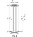
図2は、どのようにして長手方向電場が身体内で生成され得るかについての一次推定を示す概略図である。この例では、円筒形の両端の細いリング状の電極リング21、22の間に交流電圧25が印加されたときの固体の導電性円筒形本体20内の電場を考察する。電場線26によって示されるように、シリンダ20内の電場は、シリンダに沿って長手方向にほぼ均一に向けられ、またシリンダ20の内部に貫通する。いくつかの実施形態では、腫瘍治療電場を伝達するための一対の電極アレイは、一方のアレイが他方の上に配置された状態で、対象者の身体の周りにフィットする2つのリング状のアレイとして設計され得る。 FIG. 2 is a schematic diagram showing a first order estimate of how a longitudinal electric field can be generated within the body. In this example, we consider the electric field in a solid conductive
長手方向電場が細胞分裂の軸と平行である場合に腫瘍治療電場がより効果的であるので、長手方向電場の使用が大きな利点をもたらし得る。結果として、電場が印加される方向の数を増やすことは、治療されている腫瘍(分裂中の細胞の配向性が変わり得る)に対する有効性を高めることができる。特に、長手方向のアレイを使用することで、電場分布と対象者の快適さの両方を最適化できる、身体上のアレイレイアウトのための新しい選択肢が生まれます。 The use of longitudinal electric fields may provide significant advantages, as tumor treating electric fields are more effective when the longitudinal electric field is parallel to the axis of cell division. As a result, increasing the number of directions in which the electric field is applied can increase the effectiveness against the tumor being treated, where the dividing cells may change orientation. In particular, the use of longitudinal arrays opens new options for array layout on the body that can optimize both electric field distribution and subject comfort.
図3A~図3Dは、腫瘍治療電場を人体の異なる部分に伝達するように設計された電極アレイの長手方向ペアの4つの例を示す。これらの実施形態のすべてにおいて、電極アレイのそれぞれは、電極要素がそれぞれの身体部分を完全に囲むように、電極要素を対象者の身体に対して保持するように構成された基板上に取り付けられた1つ以上の電極要素を含む。いくつかの好ましい実施形態では、基板は対象者の身体との適合性を促進するために可撓性である。可撓性基板上に個々の電極要素を取り付けるための適切な手法の一例が、図6Aおよび図6Bに関連して以下に説明される。 Figures 3A-3D show four examples of longitudinal pairs of electrode arrays designed to transmit tumor-treating electric fields to different parts of the human body. In all of these embodiments, each of the electrode arrays is mounted on a substrate configured to hold the electrode elements against the subject's body such that the electrode elements completely surround the respective body portion. and one or more electrode elements. In some preferred embodiments, the substrate is flexible to facilitate conformance with the subject's body. One example of a suitable technique for mounting individual electrode elements on a flexible substrate is described below with respect to Figures 6A and 6B.
例えば、胸部または腹部に電場を伝達することを意図した図3Aの実施形態では、第1の電極アレイは、胴体の周りの位置31(例えば、対象者の腰のすぐ上)に配置され、第2の電極アレイは、対象者の首の周りの位置32に配置される。例えば、腹部に電場を伝達することを意図した図3Bの実施形態では、第1の電極アレイは、胴体の周りの位置33(例えば、対象者の腰のすぐ上)に配置され、第2の電極アレイは、胴体の周りの位置34(例えば、対象者の腹部のトップで)に配置される。例えば、肺に電場を伝達するための代替の実施形態(図示せず)では、第1の電極アレイは、胸部の下に配置され(図3Bの位置34と同様)、第2の電極アレイは、対象者の首の周りに配置される(図3Aの位置32と同様)。 For example, in the embodiment of FIG. 3A intended to deliver an electric field to the chest or abdomen, the first electrode array is placed at
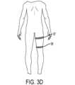
例えば、腕の一部に電場を伝達することを意図した図3Cの実施形態では、第1の電極アレイは、標的領域に近接する腕上の位置35に配置され、第2の電極アレイは、標的領域に対して遠位の腕上の位置36に配置される。肘内の標的領域は、これらの位置35、36の位置を調整することによって収容され得る。同様に、例えば、脚部の一部に電場を伝達することを意図した図3Dの実施形態では、第1の電極アレイは、標的領域に近接する脚上の位置37に配置され、第2の電極アレイは、標的領域に対して遠位の脚上の位置38に配置される。膝内の標的領域は、これらの位置37、38の位置を調整することによって収容され得る。 For example, in the embodiment of FIG. 3C intended to transmit an electric field to a portion of the arm, a first electrode array is placed at
例えば、腫瘍治療電場を脳下垂体脳、脳幹、および首に伝達することを意図した図3Eの実施形態では、第1の電極アレイは、対象者の首の周りの位置26に配置され、第2の電極アレイは、対象者の頭部の冠(クラウン)に近い位置27に配置される。これらの同じ解剖学的位置に電場を伝達することを意図した代替の実施形態である図3Fの実施形態では、第1の電極アレイは、対象者の首の周りの位置28に配置され、第2の電極アレイは、対象者の頭上の位置29に配置される。 For example, in the embodiment of FIG. 3E, which is intended to transmit a tumor-treating electric field to the pituitary brain, brainstem, and neck, a first electrode array is placed at
図3A~図3Eに示す各実施形態は、対象者の身体内の標的領域を腫瘍治療電場で治療する方法を実施するために使用され、この方法は、次のステップによってなる。(1)標的領域の長手方向の前の位置で、対象者の身体の第1の部分を囲むように1つ以上の電極の第1のセットを対象者の身体に取り付けるステップ。(2)標的領域の長手方向に続く位置で、対象者の身体の第2の部分を囲むように1つ以上の電極の第2のセットを対象者の身体に取り付けるステップ。(3)1つ以上の電極の第1のセットと1つ以上の電極の第2のセットとの間に100~500kHzの周波数の第1のAC電圧を印加するステップであって、標的領域を長手方向に通過する電場を有する第1のAC電場を印加し、第1のAC電場が、標的領域の少なくとも一部において少なくとも1V/cmの電場強度を有するように、第1のAC電圧を印加するステップ。いくつかの好ましい実施形態では、1つ以上の電極の第1および第2のセットは、対象者の身体に静電容量結合される。 Each of the embodiments shown in FIGS. 3A-3E is used to carry out a method of treating a target region within a subject's body with a tumor treatment electric field, the method comprising the following steps. (1) attaching a first set of one or more electrodes to the subject's body so as to surround a first portion of the subject's body at a position longitudinally in front of the target area; (2) attaching a second set of one or more electrodes to the subject's body to surround a second portion of the subject's body at a position longitudinally following the target area; (3) applying a first AC voltage at a frequency of 100-500 kHz between the first set of one or more electrodes and the second set of one or more electrodes, wherein the target area is Applying a first AC electric field having a longitudinally passing electric field, and applying a first AC voltage such that the first AC electric field has an electric field strength of at least 1 V/cm in at least a portion of the target area. step to do. In some preferred embodiments, the first and second sets of one or more electrodes are capacitively coupled to the subject's body.
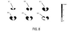
それらが使用される解剖学的位置に応じて、長手方向アレイは、以下の利点のうちの1つ以上をもたらし得る。第1に、長手方向アレイは、横方向アレイよりも高い電場強度で特定の標的領域をカバーすることを可能にし得る。例えば、従来の緯度方向アレイのみを使用して肺腫瘍を治療する場合、対象者の両側のアレイは脇の下の下に配置されなければならない。結果として、肺の上葉における電場強度は比較的低い。対照的に、(図3Aに示すように)腰の周りおよび首の周りに配置された長手方向アレイは、(図8および図9A、図9Bに関連して後述されるように)肺全体にわたってより均一な高電場強度をもたらすことができる。 Depending on the anatomical location in which they are used, longitudinal arrays can provide one or more of the following advantages. First, longitudinal arrays may allow higher electric field strengths to cover specific target areas than transverse arrays. For example, when treating lung tumors using only conventional latitudinal arrays, the arrays on each side of the subject must be placed under the armpits. As a result, the electric field strength in the upper lobe of the lung is relatively low. In contrast, longitudinal arrays positioned around the waist (as shown in FIG. 3A) and around the neck provide A more uniform high electric field strength can be provided.
第2に、特定の解剖学的位置では、長手方向アレイは、緯度方向アレイよりも体の輪郭によく接着し得る。例えば、胸部を治療するとき、胸部に配置された緯度方向アレイは身体の輪郭にうまく接着しない可能性があり(例えば、女性の乳房の場合)、アレイと身体との電気的接触が最適にならず、腫瘍内の電場強度が低下する。これらの状況では、長手方向アレイを介した電場の身体への電気的結合は、横方向アレイを介した電場の身体への電気的結合よりも良好なカバレージをもたらすことができる。 Second, at certain anatomical locations, longitudinal arrays may adhere better to body contours than latitudinal arrays. For example, when treating the chest, a latitudinal array placed on the chest may not adhere well to the contours of the body (e.g., in the case of female breasts), and electrical contact between the array and the body may not be optimal. Instead, the electric field strength within the tumor decreases. In these situations, electrical coupling of the electric fields to the body via longitudinal arrays can provide better coverage than electrical coupling of the fields to the body via transverse arrays.
第3に、対象者の身体上に配置された大きな緯度方向アレイは、運動を制限したり、特定の解剖学的位置において対象者に不快感を与えたりする可能性がある。例えば、胸部を治療するとき、(例えば、図4A、図4Bに示されるように)対象者の胸部に配置された大きな緯度方向アレイは、不快感を引き起こすか、または運動の制限さえ生じ得る。このような場合、1つのアレイで首を迂回させ、もう1つで上腹部または腰を迂回させる、アレイの長手方向ペアが、使用する対象者をより快適にすることができるので、(例えば、図3Aに示されるように)適切に設計された長手方向アレイのペアを使用して電場を伝達する際に快適性の向上に役立ち得る。 Third, a large latitudinal array placed on the subject's body can restrict movement or cause discomfort to the subject at certain anatomical locations. For example, when treating the chest, a large latitudinal array placed on the subject's chest (e.g., as shown in FIGS. 4A, 4B) can cause discomfort or even limit movement. In such cases, longitudinal pairs of arrays, one around the neck and another around the upper abdomen or lower back, can make the subject more comfortable to use (e.g., Using a pair of well-designed longitudinal arrays (as shown in FIG. 3A) can help improve comfort in transmitting the electric field.
第4の重要な利点は、長手方向アレイを使用して生成される電場が、横方向アレイ(すなわち、前後方向または横方向に配置された電極アレイのセット)によって生成される電場に対してほぼ垂直であることである。したがって、(例えば、図3A~図3Dに示されるような)長手方向電場を生成するように設計されたアレイは、複数の異なる方向の電場で標的領域を治療するために緯度方向電場を生成するように設計された従来のアレイと組み合わせることができ、それによって治療の効果を高める。長手方向アレイの利用可能性はまた、電場分布および対象者の快適さを最適化する電極のレイアウトを見つけるためのさらなる自由度を提供する。 A fourth important advantage is that the electric field generated using a longitudinal array is approximately It should be vertical. Thus, an array designed to produce a longitudinal electric field (eg, as shown in FIGS. 3A-3D) produces a latitudinal electric field to treat a target region with multiple different directional electric fields. It can be combined with conventional arrays designed to enhance the efficacy of therapy. The availability of longitudinal arrays also provides additional degrees of freedom for finding electrode layouts that optimize electric field distribution and subject comfort.
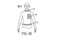
図4A~4Hは、(例えば、図3A~Fに関連して上述したものと同様の)一対の長手方向アレイが一対の緯度方向アレイと組み合わされた例を示す。これらの状況のそれぞれにおいて、電極がそれらのそれぞれの位置に固定された後、(a)標的領域に長手方向電場を課すために、長手方向に配置された第1および第2の電極セット間にAC電圧が印加され、(b)標的領域に緯度方向電場を課すために、緯度方向に配置された第3および第4のセットの電極間にAC電圧が印加される。これらのステップ(a)および(b)は、標的領域に課されている電場の方向を繰り返し切り替えるために、治療期間中に交互の順序で繰り返される。いくつかの実施形態では、切り替え速度は0.25から2秒の間である。治療は一度に何時間も続けることが好ましいので、これらのステップ(a)および(b)のそれぞれは、好ましくは少なくとも10,000回繰り返される。好ましくは、AC電圧の周波数は100~500kHzの間で、いくつかの好ましい実施形態では、周波数は125~250kHzの間である。(例えば、膵臓癌および特定の種類の肺癌を治療するための)いくつかの好ましい実施形態では、周波数は140~160kHzの間である。(例えば、卵巣癌を治療するための)いくつかの好ましい実施形態では、周波数は190~210kHzの間である。好ましくは、標的領域に印加されるそれぞれの電場は少なくとも1V/cmの電場強度を有する。 Figures 4A-4H show an example in which a pair of longitudinal arrays (eg, similar to those described above with respect to Figures 3A-F) are combined with a pair of latitudinal arrays. In each of these situations, after the electrodes have been fixed in their respective positions, (a) between the first and second sets of longitudinally arranged electrodes to impose a longitudinal electric field on the target region. An AC voltage is applied, and (b) the AC voltage is applied between the third and fourth sets of latitudinally arranged electrodes to impose a latitudinal electric field on the target region. These steps (a) and (b) are repeated in alternating order during the treatment period to repeatedly switch the direction of the electric field imposed on the target region. In some embodiments, the switching speed is between 0.25 and 2 seconds. Each of these steps (a) and (b) is preferably repeated at least 10,000 times, as treatment is preferably continued for many hours at a time. Preferably, the frequency of the AC voltage is between 100-500 kHz, and in some preferred embodiments the frequency is between 125-250 kHz. In some preferred embodiments (eg, for treating pancreatic cancer and certain types of lung cancer), the frequency is between 140-160 kHz. In some preferred embodiments (eg, for treating ovarian cancer), the frequency is between 190-210 kHz. Preferably, each electric field applied to the target area has an electric field strength of at least 1 V/cm.
例えば、胸部に電場を伝達することを意図している図4A/Bの実施形態では、長手方向アレイは、対象者の腰の直ぐ上の位置31に配置された第1の電極アレイと、対象者の首の周りの位置32に配置された第2の電極アレイとによって実施される。さらに、緯度方向アレイは、対象者の胸部の位置41に配置された第3の電極アレイと、対象者の背中の位置42に配置された第4の電極アレイとを備える。この実施形態では、緯度方向電場の電場線方向は前方から後方へ延びる。 For example, in the embodiment of Figures 4A/B, which is intended to transmit an electric field to the chest, the longitudinal arrays are a first electrode array positioned at
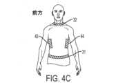
例えば、胸部に電場を伝達することを意図している図4C/Dの実施形態でも、長手方向アレイは図4A/4Bと同じ方法で実施されるが、緯度方向アレイは、第3の電極アレイを対象者の右側の位置43に配置し、第4の電極アレイを対象者の左側の位置44に配置して実施される。この実施形態では、緯度方向電場の電場線方向は横方向に延びる。 For example, in the embodiment of Figures 4C/D, which is intended to transmit an electric field to the chest, the longitudinal arrays are implemented in the same manner as in Figures 4A/4B, but the latitudinal arrays are replaced by a third electrode array. is placed at
例えば、胸部に電場を伝達することを意図している図4E/Fの実施形態でも、長手方向アレイは図4A/4Bと同じ方法で実施されるが、緯度方向アレイは、第3の電極アレイを対象者の胸部左側の位置45に配置し、第4の電極アレイを対象者の背中右側の位置46に配置して実施される。この実施形態では、緯度方向電場の電場線方向は、対象者の胸部を通って前から後ろへ斜めに延びる。 For example, in the embodiment of Figures 4E/F, which is intended to transmit an electric field to the chest, the longitudinal array is implemented in the same manner as in Figures 4A/4B, but the latitudinal array is the third electrode array. is placed at
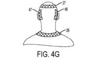
例えば、腫瘍治療電場を乳頭下脳に伝達することを意図している図4Gの実施形態では、長手方向アレイは、対象者の首の周りの位置26に配置された第1の電極アレイと、対象者の頭部の冠に近い位置27に配置された第2の電極アレイとによって実施される。さらに、緯度方向アレイは、対象者の頭部の左側の位置47に配置された第3の電極アレイと、対象者の頭部の右側の位置48に配置された第4の電極アレイとを備える。この実施形態では、緯度方向電場の電場線方向は横方向に延びる。あるいは、緯度方向アレイは、対象者の頭部の前後の位置に配置された第3および第4の電極(図示せず)を使用して実施されてもよい。 For example, in the embodiment of FIG. 4G, which is intended to transmit a tumor-treating electric field to the infrapapillary brain, the longitudinal array includes a first electrode array positioned at
図4Hの実施形態は、第1の電極アレイが対象者の首の周りの位置28に配置され、第2の電極アレイが対象者の頭上の位置29に配置されることを除いて、図4Gの実施形態と同様である。 The embodiment of Figure 4H is similar to that of Figure 4G, except that the first electrode array is placed at
図4A~図4Hを参照して上述した実施形態に加えて、長手方向に配置された一対のアレイと緯度方向に配置された一対のアレイとを組み合わせる多種多様な代替構成が、広範囲の解剖学的構造で使用するために容易に想定され、関連分野の当業者には明らかであり得る。 In addition to the embodiments described above with reference to FIGS. 4A-4H, a wide variety of alternative configurations combining a pair of longitudinally positioned arrays and a pair of latitudinally positioned arrays are available for a wide range of anatomy. can be readily envisioned and apparent to those of ordinary skill in the relevant arts for use in any given construction.
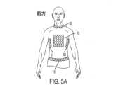
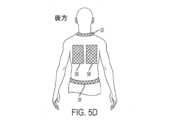
図5A~図5Dは、(例えば、図3A~図Fに関連して上述したものと同様の)一対の長手方向アレイが、二対の緯度方向アレイと組み合わされる例を示す。これらの状況のそれぞれにおいて、(a)標的領域に長手方向電場を課すために長手方向に配置された第1および第2の電極セットの間にAC電圧が印加され、(b)標的領域に第1の緯度方向電場を課すために緯度方向に配置された第3および第4の電極セットの間にAC電圧が印加され、(c)標的領域に第2の緯度方向電場を課すために緯度方向に配置された第5および第6の電極セットの間にAC電圧が印加される。第1の緯度方向電場と第2の緯度方向電場との間の角度は、好ましくは60°~120°の間で、最も好ましいのはできるだけ90°に近い角度である。これらのステップ(a)、(b)、および(c)は、3つのそれぞれの方向の間で、標的領域に課されている電場方向を繰り返し切り替えるために、治療期間中に交互の順序で繰り返される。いくつかの実施形態では、切り替え速度は0.25から2秒の間である。治療は一度に何時間も続けることが好ましいので、これらのステップ(a)、(b)、および(c)のそれぞれは、好ましくは少なくとも10,000回繰り返される。 Figures 5A-5D show an example in which a pair of longitudinal arrays (eg, similar to those described above with respect to Figures 3A-F) are combined with two pairs of latitudinal arrays. In each of these situations, (a) an AC voltage is applied between first and second sets of longitudinally arranged electrodes to impose a longitudinal electric field on the target region; (c) an AC voltage is applied between third and fourth sets of latitudinally arranged electrodes to impose one latitudinal electric field; An AC voltage is applied between the fifth and sixth electrode sets placed at . The angle between the first latitudinal electric field and the second latitudinal electric field is preferably between 60° and 120°, most preferably as close to 90° as possible. These steps (a), (b), and (c) are repeated in alternating order during the treatment period to repeatedly switch the direction of the electric field imposed on the target region between three respective directions. be In some embodiments, the switching speed is between 0.25 and 2 seconds. Each of these steps (a), (b) and (c) is preferably repeated at least 10,000 times, as the treatment is preferably continued for many hours at a time.
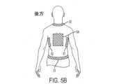
例えば、胸部に電場を伝達することを意図している図5A/Bの実施形態では、長手方向アレイは、対象者の腰の直ぐ上の位置31に配置された第1の電極アレイと、対象者の首の周りの位置32に配置された第2の電極アレイとによって実施される。さらに、第1の緯度方向アレイは、前から後ろに延びる電場線を有する第1の緯度方向電場を生成するために、対象者の胸部の位置41に配置された第3の電極アレイと、対象者の背中の位置42に配置された第4の電極アレイとを備える。最後に、第3の緯度方向アレイは、横方向に延びる電場線を有する第2の緯度方向電場を生成するために、対象者の身体の右側の位置51に配置された第5の電極アレイと、対象者の身体の左側の位置52に配置された第6の電極アレイとを備える。 For example, in the embodiment of Figures 5A/B, which is intended to transmit an electric field to the chest, the longitudinal arrays are a first electrode array positioned at
図5C/Dの実施形態は、図5A/Bの実施形態と同様であるが、第3および第4の電極アレイが対象者の正面の位置55および背面の位置56にそれぞれ配置されている点と、第5および第6の電極アレイが対象者の前面の位置57および背面の位置58にそれぞれ配置されている点とにおいて異なる。この実施形態では、第1の緯度方向電場が前方右から後方左へ延びる電場線を有し、第2の緯度方向電場が前方左から後方右へ延びる電場線を有する。第1の緯度方向電場と第2の緯度方向電場との間の角度は、好ましくは60°~120°の間であり、最も好ましいのはできるだけ90°に近い角度である。 The embodiment of Figures 5C/D is similar to the embodiment of Figures 5A/B, except that the third and fourth electrode arrays are positioned at
ここでもまた、図5A~図5Dを参照して上述した2つの実施形態に加えて、長手方向に配置された1対のアレイと緯度方向に配置された2対のアレイとを組み合わせる多種多様な代替構成が解剖学的位置の広範囲での使用のために容易に想定され、関連分野の当業者には明らかであり得る。 Again, in addition to the two embodiments described above with reference to FIGS. 5A-5D, a wide variety of combinations of one pair of longitudinally arranged arrays and two pairs of latitudinally arranged arrays are possible. Alternative configurations are readily envisioned for use in a wide range of anatomical locations and may be apparent to those skilled in the relevant arts.
上述した図3~図5の説明は、様々なペアの電極が対象者の身体上に配置される位置を説明しているが、それらの電極のセット構成については説明していない。図6Aおよび図6Bに示す構成を含むがこれらに限定されない様々な構成が、これらの電極のセットを実施するために使用され得る。 The descriptions of FIGS. 3-5 above describe the locations where the various pairs of electrodes are placed on the subject's body, but do not describe the set configuration of those electrodes. Various configurations can be used to implement these electrode sets, including but not limited to the configurations shown in FIGS. 6A and 6B.
図6Aは、一組の電極60を対象者の身体に固定するのに適した第1の構成を示す。この実施形態では、各組の電極60は、帯状基板62上に取り付けられた複数の個別電極要素61を含む。帯状基板62は、それが使用される特定の身体部分にフィットするような形状および寸法である。例えば、図3Aの位置31に示されている長手方向アレイの場合、基板62はベルトに似た可撓性基板で、図3Aの位置32に示されている長手方向アレイの場合、基板62はチョーカーに似た可撓性基板で、また、図3Eの位置27に示されている長手方向アレイの場合、基板62はヘッドバンドに似た可撓性基板である。基板62の役割は、個々の電極要素61を対象者の皮膚に対して保持することで、それによってこれらの要素が皮膚と良好に接触する。任意選択で、導電性ゲルを電極要素61と対象者の皮膚との間に塗布してもよい。 FIG. 6A shows a first configuration suitable for securing a set of
いくつかの実施形態では、個々の電極要素61のそれぞれは、従来のNovocure TTF-100L(登録商標)トランスデューサアレイで使用されている電極要素のように、高誘電率を有するディスク状の静電容量結合電極である。代替の実施形態では、複数の個別電極要素61を使用する代わりに、単一電極要素(図示せず)を使用することができ、その場合、単一電極要素は好ましくはそれが使用される対象者の身体の特定部分にフィットするように可撓性または輪郭を有する。 In some embodiments, each
各組の電極60内の個々の電極要素61は、適切な配線63を使用して一緒に配線される。例えば、個々の電極要素61は、並列に、直列に、または並列/直列の組み合わせで配線され得る。必要に応じて、この配線63はコネクタ64で終端され得る。このコネクタ64は、電極60のセットとAC信号発生器65とを接続するために使用され、AC信号発生器65は二組の電極間に電圧を印加することができる。 The
図6Bは、パネル状の電極60´セットを対象者の身体に固定するのに適した第2の構成を示す。この構成は、パネル状の基板62´に装着された複数の個別電極要素61を含む。この図6Bの実施形態における配線63およびコネクタ64は、図6Aの対応する要素と同様である。この図6Bの実施形態は、(図4~図5に示す)位置41~58に配置するため、並びに、これらの実施形態を参照しながら上述した横方向電場を発生させるために最も適している。 FIG. 6B shows a second configuration suitable for securing a set of panel electrodes 60' to a subject's body. This configuration includes a plurality of
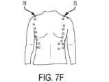
電極要素が配置される解剖学的位置に基づいて、複数の個々の電極要素を取り付けるための多種多様な代替基板構成が当業者には明らかであろう。図7A~図7Fは、そのような3つの構成における電極要素の配置を示す。図7A/Bに示される長手方向の電極セット71、72(それぞれ正面図および背面図を示す)のための電極要素を支持する基板は、相当する解剖学的構造に適した寸法に縮尺された、図6Aに示される帯状構成と同様である。図7C/D(それぞれ正面図および背面図を示す)に示された前/後の緯度方向電極セット73/74用の電極要素と、図7E/F(それぞれ正面図および背面図を示す)に示された右/左の緯度方向電極セット75/76用の電極要素と、を支持する基板は、相当する解剖学的構造に適した大きさに縮尺および形状が合わせられた、図6Bに示されるパネル状構成と同様である。図7A/B、図7C/D、および図7E/Fの3つの電極構成のすべてを組み合わせ、3つの異なる電場方向を提供するためにこれら3組の電極間で電場を循環させることによって、患者の快適性を維持しつつ、肺の上葉に対する優れた電場範囲を形成することができる。 A wide variety of alternative substrate configurations for mounting multiple individual electrode elements will be apparent to those skilled in the art based on the anatomical locations in which the electrode elements are placed. Figures 7A-7F show the placement of the electrode elements in three such configurations. The substrates supporting the electrode elements for the longitudinal electrode sets 71, 72 shown in FIGS. 7A/B (shown in front and rear views, respectively) were scaled to dimensions suitable for the corresponding anatomy. , similar to the strip configuration shown in FIG. 6A. Electrode elements for anterior/posterior latitudinal electrode sets 73/74 shown in FIGS. 7C/D (showing front and rear views respectively) and FIG. 7E/F (showing front and rear views respectively). The electrode elements for the illustrated right/left latitudinal electrode sets 75/76 and the supporting substrate are shown in FIG. It is similar to the panel-like configuration that is used. By combining all three electrode configurations of FIGS. 7A/B, 7C/D, and 7E/F and cycling the electric field between these three sets of electrodes to provide three different electric field directions, the patient Excellent electric field coverage to the upper lobes of the lungs can be created while maintaining the comfort of .
有限要素計算法により、長手方向アレイが相当する解剖学的構造への効果的な貫通を提供できることが明らかになった。一例では、図7A/Bに示すように、複数のセラミックディスク形状の電極要素が、現実的な計算ファントムにおける腰部に対応する第1の位置71と、首部に対応する第2の位置72とに分配される。 Finite element calculations have revealed that longitudinal arrays can provide effective penetration into corresponding anatomy. In one example, as shown in FIGS. 7A/B, a plurality of ceramic disk-shaped electrode elements are placed at a
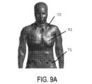
図8は、有限要素シミュレーションを用いて計算された、肺を通って規則的な垂直間隔で隔てられた軸スライス81~86のこの例についての電場強度を示す。このシミュレーションは、長手方向アレイを使用して、大部分の肺を通して1~4V/cmの間の電場強度を得ることが可能であることを明らかにする。図9A/Bは、このシミュレーションについて、それぞれ身体および肺を通る長手方向の電場の電場線の方向91を示す。これらの図は、これらの電場線の長手方向の特性を示している。 FIG. 8 shows the electric field strength for this example of axial slices 81-86 at regular vertical intervals through the lung, calculated using finite element simulation. This simulation reveals that it is possible to obtain electric field strengths between 1 and 4 V/cm through most of the lung using longitudinal arrays. Figures 9A/B show the
場合によっては、腫瘍治療電場を使用して腫瘍を治療するには、少なくとも1対の長手方向アレイを使用することが唯一の実用的な方法であり得る。例えば、腫瘍が膝や肘などの関節にある場合、横方向の電極セットのみを使用すると、対象者の可動性が著しく損なわれる可能性がある。 In some cases, using at least one pair of longitudinal arrays may be the only practical way to treat a tumor using a tumor treatment electric field. For example, if the tumor is in a joint such as a knee or elbow, using only a lateral set of electrodes can significantly impair the subject's mobility.
図10Aおよび図10Bは、この可動性の問題を克服する、2組の長手方向アレイを使用して電場を膝に伝達することを意図した実施形態の内側および外側をそれぞれ示す図である。この実施形態では、第1の基板が、膝に近接する位置101で脚の前面を部分的に囲むように脚に対して1つ以上の電極の第1のセットを保持し、第2の基板が、膝に対して遠位の位置102で脚の裏側を部分的に囲むように脚に対して1つ以上の電極の第2のセットを保持し、第3の基板が、膝に近接する位置103で脚の裏側を部分的に囲むように脚に対して1つ以上の電極の第3のセットを保持し、第4の基板が、膝に対して遠位の位置104で脚の前面を部分的に囲むように脚に対して1つ以上の電極の第4のセットを保持する。 Figures 10A and 10B show the medial and lateral views, respectively, of an embodiment intended to transmit the electric field to the knee using two sets of longitudinal arrays that overcome this mobility problem. In this embodiment, a first substrate holds a first set of one or more electrodes against the leg so as to partially surround the anterior surface of the leg at
位置101~104の各セットの電極は、脚の輪郭に一致する開いた円弧のような形状であることが好ましい。この円弧形状は、図6Aに関連して上述したように、可撓性基板を用いて達成することができ、その上に複数の個別電極要素が取り付けられる。あるいは、円弧形状は、その上に1つ以上の電極要素が取り付けられる剛性基板を使用しても達成され得る。開いた円弧構成が電極アレイに使用されるとき、電場が確実に身体を貫通するように、任意の所与のペアのアレイを使用される身体部分の反対側に配置することが重要であって、これは所与の電極ペアの両方の円弧が身体の同じ側に配置されている場合、重要な電場が身体の表在領域にのみ発生する可能性があるためである。 Each set of electrodes at positions 101-104 is preferably shaped like an open arc that conforms to the contour of the leg. This arcuate shape can be achieved using a flexible substrate, as described above in connection with FIG. 6A, on which a plurality of individual electrode elements are mounted. Alternatively, an arcuate shape can be achieved using a rigid substrate onto which one or more electrode elements are mounted. When an open arc configuration is used for electrode arrays, it is important to place any given pair of arrays on opposite sides of the body part being used to ensure that the electric field penetrates the body. , because if both arcs of a given electrode pair are placed on the same side of the body, the significant electric field can only occur in superficial regions of the body.
この実施形態では、位置101に固定された電極のセットと位置102に固定された電極のセットとの間に第1のAC電圧が印加され、破線106の一般方向に延びる電場線を有する電場が生じる。次に、位置103に固定された電極セットと位置104に固定された電極のセットとの間に第2のAC電圧が印加され、その結果、点線107の一般方向に延びる電場線を有する電場が生じる。この構成は、関節を通してX字形を形成する2つの電場をもたらす。これら2つの電場の方向(106、107)は垂直ではないかもしれないが、それらの電場の間の角度が、単一方向の電場に対する改善された結果をもたらすのに十分に大きいであろう。好ましくは、第1および第2のAC電圧の周波数は100から500kHzの間である。いくつかの好ましい実施形態では、この周波数は125から250kHzの間である。2つの電場の強度は、標的領域の少なくとも一部分において少なくとも1V/cmであることが好ましい。 In this embodiment, a first AC voltage is applied between a set of electrodes fixed at
別の実施形態では、関節の上下に位置する一対の長手方向アレイを関節の外側に配置された一対の緯度方向アレイと組み合わせることによって膝を治療することができる。これらの実施形態では、長手方向アレイは、(例えば、図3Dに見られるように)脚を完全に囲むことができ、または(例えば、図10に関連して上述したように)脚を部分的に囲み得る。 In another embodiment, the knee can be treated by combining a pair of longitudinal arrays located above and below the joint with a pair of latitudinal arrays located outside the joint. In these embodiments, the longitudinal array can completely surround the legs (eg, as seen in FIG. 3D) or partially surround the legs (eg, as described above with respect to FIG. 10). can be surrounded by
相当する寸法に適切な変更がなされるならば、図10に関連して上述した膝の文脈における同じ概念が、肘の文脈において、または他の関節にも適用され得ることに留意されたい。 It should be noted that the same concepts in the context of the knee discussed above in connection with FIG. 10 can be applied in the context of the elbow or to other joints, provided appropriate changes are made to the corresponding dimensions.
いくつかの場合(例えば、図3A~3Fの実施形態)、それらが配置される身体部分を完全に回避するようにアレイは設計され、他の場合(例えば、図10A~Bの実施形態)、それらが配置される身体部分を完全に回避しないようにアレイは設計される。しかしながら、これらのアレイ構成の両方において、それぞれのアレイは長手方向軸に沿って異なる位置に配置されなければならない。 In some cases (e.g., the embodiment of Figures 3A-3F), the arrays are designed to completely avoid the body part on which they are placed, and in other cases (e.g., the embodiment of Figures 10A-B), Arrays are designed so that they do not completely avoid the body part on which they are placed. However, in both of these array configurations, each array must be placed at different positions along the longitudinal axis.
腫瘍治療電場は、電場生成装置によって生成された電場を体内に静電容量結合する電極アレイを介して伝達されてもよい。例えば、米国特許第7,715,921号明細書(特許文献1)に記載されているアレイ設計構造は、長手方向アレイの設計に組み込むことができる。電極アレイはまた、米国特許第8,715,203号明細書(特許文献2)に記載されているように、対象者の皮膚に対して配置されるように設計されている複数のセラミック素子を含む複合電極として設計され得る。 The tumor treatment electric field may be delivered via an electrode array that capacitively couples the electric field generated by the electric field generator into the body. For example, the array design structure described in US Pat. No. 7,715,921 can be incorporated into the longitudinal array design. The electrode array also includes a plurality of ceramic elements designed to be placed against the skin of a subject as described in US Pat. No. 8,715,203. It can be designed as a composite electrode comprising:
いくつかの実施形態では、アレイは、薄い導電性ゲルを介して身体に接続されている高誘電率を有する1式のセラミックディスクとして設計されている。各アレイのディスクは、フレックスワイヤを介して電気的に相互接続されており、アレイが対象者の身体にしっかりと接着するように、接着テープがディスク上に配置されている。長手方向アレイを作成するための構成要素は、NovoTTF-100L(登録商標)を使用して腫瘍治療電場を胴体に伝達するのと同様に、Optune(登録商標)を使用して腫瘍治療電場を頭部に伝達するために現在使用されているものと同様であり得る。セラミック要素は、並列に、直列に、または並列と直列の任意の組み合わせ(例えば、各グループが直列に配線された3つのディスクを含む、並列に配線された3つのグループ)に配線され得る。 In some embodiments, the array is designed as a set of ceramic discs with a high dielectric constant that are connected to the body via a thin conductive gel. The discs of each array are electrically interconnected via flex wires, and adhesive tape is placed over the discs so that the array adheres firmly to the subject's body. The building block for creating the longitudinal array is similar to using the NovoTTF-100L® to transmit the tumor-treating electric field to the torso, using Optune® to transmit the tumor-treating electric field to the head. can be similar to those currently used to communicate to departments. The ceramic elements may be wired in parallel, in series, or in any combination of parallel and series (e.g., three groups wired in parallel, each group containing three discs wired in series).
任意選択的に、アレイレイアウトの設計は有限要素シミュレーションの助けを借りて実行することができ、これは長手方向アレイの任意の特定の設計がもたらすであろう予想電場分布を計算するために使用され得る。そのような設計は、最大電場強度を標的領域に伝達するように最適化することができる。 Optionally, the design of the array layout can be performed with the aid of finite element simulations, which are used to calculate the expected electric field distribution that any particular design of longitudinal array would result in. obtain. Such designs can be optimized to deliver maximum electric field strength to the target area.
任意選択で、各アレイ内のディスクは、それらが異なるサイズの対象にフィットすることを可能にするように接続され得る(例えば、各アレイは、少数のディスクを有するいくつかの接続パッチを含み得、或いは、ディスクは可撓性コネクタで接続され得る)。 Optionally, the disks within each array may be connected to allow them to fit objects of different sizes (e.g., each array may contain several connection patches with a small number of disks). , or the discs may be connected with flexible connectors).
上記の実施形態は人間対象に関して説明されているが、それらは適切な修正を行うことによって他の動物(例えば、犬、馬等)にも使用することができ、これは当業者には明らかであろう。 Although the above embodiments are described with respect to human subjects, they can be used with other animals (e.g., dogs, horses, etc.) with appropriate modifications, as will be apparent to those skilled in the art. be.
本発明を特定の実施形態を参照して開示したが、添付の特許請求の範囲に定義されるように、本発明の領域と範囲から逸脱することなく、記載した実施形態に対する多数の修正、改定、および変更が可能である。したがって、本発明は記載された実施形態に限定されず、特許請求の範囲の文言およびその均等物によって定義される全範囲を含むことが意図されている。 Although the present invention has been disclosed with reference to particular embodiments, numerous modifications and revisions to the described embodiments may be made without departing from the sphere and scope of the invention as defined in the appended claims. , and can be changed. Therefore, it is intended that the invention not be limited to the described embodiments, but that it have the full scope defined by the language of the following claims and equivalents thereof.
[第1項]
対象者の身体内の標的領域を腫瘍治療電場で治療するための装置であって、長手方向軸を有する対象者の身体の一部分に標的領域を配置する装置において、
1つ以上の静電容量結合電極の第1のセットと、
1つ以上の電極の前記第1のセットを対象者の身体に対して保持するように構成された第1の基板であって、1つ以上の電極の前記第1のセットが、長手方向で前記標的領域の前の位置で、前記対象者の身体の第1の部分を囲む、第1の基板と、
1つ以上の静電容量結合電極の第2のセットと、
1つ以上の電極の前記第2のセットを対象者の身体に対して保持するように構成された第2の基板であって、1つ以上の電極の前記第2のセットが、長手方向で前記標的領域の次の位置で、前記対象者の身体の第2の部分を囲む、第2の基板と、
1つ以上の静電容量結合電極の第3のセットと、
1つ以上の電極の前記第3のセットを保持する第3の基板であって、1つ以上の電極の前記第1のセットと1つ以上の電極の前記第2のセットとの間の長手方向の位置で、前記対象者の身体に対して1つ以上の電極の前記第3のセットを前記標的領域の第1の側に保持する、第3の基板と、
1つ以上の静電容量結合電極の第4のセットと、
1つ以上の電極の前記第4のセットを保持する第4の基板であって、1つ以上の電極の前記第1のセットと1つ以上の電極の前記第2のセットとの間の長手方向の位置で、前記対象者の身体に対して1つ以上の電極の前記第4のセットを、前記第1の側とは反対側である前記標的領域の第2の側に保持する、第4の基板と、
を含んでなることを特徴とする装置。
[第2項]
(a)1つ以上の電極の前記第1のセットと前記第2のセットとの間に100~500kHzの周波数を有するAC電圧と、(b)1つ以上の電極の第3のセットと1つ以上の電極の第4のセットとの間に100~500kHzの周波数を有するAC電圧と、を次から次へと繰り返し交互に生成するように構成されたAC電圧発生器をさらに含んでなることを特徴とする、第1項に記載の装置。
[第3項]
(a)1つ以上の電極の前記第1のセットと前記第2のセットとの間に125~250kHzの周波数のAC電圧を生成するように構成されたAC電圧発生器と、(b)1つ以上の電極の第3のセットと1つ以上の電極の第4のセットとの間に125~250kHzの周波数を有するAC電圧と、を次から次へと繰り返し交互に生成するように構成されたAC電圧発生器をさらに含んでなることを特徴とする、第1項に記載の装置。
[第4項]
1つ以上の電極の前記第1のセットが第1の複数フラット電極要素を含み、1つ以上の電極の前記第2のセットが第2の複数フラット電極要素を含むことを特徴とする、第1項に記載の装置。
[第5項]
前記第1の基板および前記第2の基板のそれぞれが可撓性であることを特徴とする、第4項に記載の装置。
[第6項]
前記第1の基板および前記第2の基板のそれぞれが、前記対象者の身体の胴体の周りにフィットするような形状および寸法であることを特徴とする、第1項に記載の装置。
[第7項]
前記第1の基板が前記対象者の身体の胴体の周りにフィットするような形状および寸法であり、前記第2の基板が前記対象者の身体の首の周りにフィットするような形状および寸法であることを特徴とする、第1項に記載の装置。
[第8項]
前記第1の基板が前記対象者の身体の首の周りにフィットするような形状および寸法であり、前記第2の基板が前記対象者の身体の頭部の周りにフィットするような形状および寸法であることを特徴とする、第1項に記載の装置。
[第9項]
前記第1の基板が前記対象者の身体の首の周りにフィットするような形状および寸法であり、前記第2の基板が前記対象者の身体の頭部にフィットするような形状および寸法であることを特徴とする、第1項に記載の装置。
[第10項]
前記第1の基板および第2の基板のそれぞれが、前記対象者の身体のリムの周りにフィットするような形状および寸法であることを特徴とする、第1項に記載の装置。
[第11項]
1つ以上の静電容量結合電極の第5のセットと、
1つ以上の電極の前記第5のセットを保持する第5の基板であって、1つ以上の電極の前記第1のセットと1つ以上の電極の前記第2のセットとの間の長手方向の位置で、前記対象者の身体に対して1つ以上の電極の前記第5のセットを前記標的領域の第3の側に保持する、第5の基板と、
1つ以上の静電容量結合電極の第6のセットと、
1つ以上の電極の前記第6のセットを保持する第6の基板であって、1つ以上の電極の前記第1のセットと1つ以上の電極の前記第2のセットとの間の長手方向の位置で、前記対象者の身体に対して1つ以上の電極の前記第6のセットを、前記第3の側とは反対側である前記標的領域の第4の側に保持する、第6の基板と、
をさらに含むことを特徴とする、第1項に記載の装置。
[第12項]
対象者の身体内の標的領域を腫瘍治療電場で治療する方法であって、長手方向軸を有する前記対象者の身体の一部分に前記標的領域が配置される方法において、
前記標的領域の長手方向の前の位置で、前記対象者の身体の第1の部分を囲むように、1つ以上の電極の第1のセットを前記対象者の身体に取り付けるステップと、
前記標的領域の長手方向に続く位置で、前記対象者の身体の第2の部分を囲むように、1つ以上の電極の第2のセットを前記対象者の身体に取り付けるステップと、
1つ以上の電極の前記第1のセットと1つ以上の電極の前記第2のセットとの間に100~500kHzの周波数を有する第1のAC電圧を印加するステップであって、前記標的領域を長手方向に通過する電場線を有する第1のAC電場を印加し、前記第1のAC電場が、前記標的領域の少なくとも一部において少なくとも1V/cmの電場強度を有する、第1のAC電圧を印加するステップと、
を含んでなることを特徴とする方法。
[第13項]
1つ以上の電極の前記第1のセットおよび前記第2のセットのそれぞれが、前記対象者の身体に静電容量結合されていることを特徴とする、第12項に記載の方法。
[第14項]
1つ以上の電極の前記第1のセットと1つ以上の電極の前記第2のセットとの間の長手方向の位置で、前記標的領域の第1の側に、前記対象者の身体に1つ以上の電極の第3のセットを取り付けるステップと、
1つ以上の電極の前記第1のセットと1つ以上の電極の前記第2のセットとの間の長手方向の位置で、前記標的領域の前記第1の側の反対側である第2の側に、前記対象者の身体に1つ以上の電極の第4のセットを取り付けるステップと、
1つ以上の電極の前記第3のセットと1つ以上の電極の前記第4のセットとの間に100~500kHzの周波数を有する第2のAC電圧を印加するステップであって、前記標的領域を通過する第2のAC電場を印加し、前記第2のAC電場が、前記標的領域の少なくとも一部において少なくとも1V/cmの電場強度を有する、第2のAC電圧を印加するステップと、
をさらに含んでなることを特徴とする、第12項に記載の方法。
[第15項]
前記1つ以上の電極の前記第1のセット、前記第2のセット、前記第3のセット、および前記第4のセットのそれぞれが前記対象者の身体に静電容量結合されていることを特徴とする、第14項に記載の方法。
[第16項]
前記第1のAC電圧および前記第2のAC電圧のそれぞれが、125~250kHzの周波数を有することを特徴とする、第15項に記載の方法。
[第17項]
前記第1のAC電圧を印加するステップと前記第2のAC電圧を印加するステップとが次から次へと交互に少なくとも10,000回繰り返されることを特徴とする、第16項に記載の方法。
[第18項]
1つ以上の電極の前記第1のセットと1つ以上の電極の前記第2のセットとの間の長手方向の位置で、前記標的領域の第3の側に、前記対象者の身体に1つ以上の電極の第5のセットを取り付けるステップと、
1つ以上の電極の前記第1のセットと1つ以上の電極の前記第2のセットとの間の長手方向の位置で、前記標的領域の前記第3の側の反対側である第4の側に、前記対象者の身体に1つ以上の電極の第6のセットを取り付けるステップと、
1つ以上の電極の前記第5のセットと1つ以上の電極の前記第6のセットとの間に100~500kHzの周波数で第3のAC電圧を印加するステップであって、前記標的領域を通過する第3のAC電場を印加し、前記第3のAC電場が、前記標的領域の少なくとも一部において少なくとも1V/cmの電場強度を有する、第3のAC電圧を印加するステップと、
をさらに含んでなることを特徴とする、第14項に記載の方法。
[第19項]
前記第1のAC電圧を印加するステップと前記第2のAC電圧を印加するステップと前記第3のAC電圧を印加するステップとが、次から次へと交互に少なくとも10,000回繰り返されることを特徴とする、第18項に記載の方法。
[第20項]
1つ以上の電極の前記第1のセットが、前記対象者の身体の第1の部分の周りに分布する第1の複数フラット電極要素を含み、1つ以上の電極の前記第2のセットが、前記対象者の身体の第2の部分の周りに分布する第2の複数フラット電極要素を含むことを特徴とする、第12項に記載の方法。
[第21項]
前記標的領域が前記対象者の身体の胴体内に配置され、1つ以上の電極の前記第1のセットが前記標的領域の下方で前記対象者の胴体の周りに配置され、1つ以上の電極の前記第2のセットが前記標的領域の上方で前記対象者の胴体の周りに配置されていることを特徴とする、第12項に記載の方法。
[第22項]
前記対象者は首を有し、前記標的領域が前記対象者の身体の胴体内に配置され、1つ以上の電極の前記第1のセットが、前記標的領域の下方で前記対象者の胴体の周りに配置され、1つ以上の電極の前記第2のセットが、前記対象者の前記首の周りに配置されていることを特徴とする、第12項に記載の方法。
[第23項]
前記対象者は頭部と首を有し、前記標的領域が前記対象者の前記頭部内に配置され、1つ以上の電極の前記第1のセットが前記対象者の前記首の周りに配置され、1つ以上の電極の前記第2のセットが前記対象者の前記頭部の周りに配置されていることを特徴とする、第12項に記載の方法。
[第24項]
前記標的領域が前記対象者の身体のリムに配置され、前記長手方向軸が前記リムを通って近位から遠位方向に延び、1つ以上の電極の前記第1のセットが、前記標的領域に対して近い位置で前記リムの周りに配置され、1つ以上の電極の前記第2のセットが、前記標的領域に対し遠い位置で前記リムの周りに配置されていることを特徴とする、第12項に記載の方法。
[第25項]
対象者の身体のリム内の標的領域を腫瘍治療電場で治療するための装置であって、
1つ以上の静電容量結合電極の第1のセットと、
1つ以上の電極の前記第1のセットを対象者の身体に対して保持するように構成された第1の基板であって、1つ以上の電極の前記第1のセットが、前記標的領域に対し近い位置で、前記リムの第1の側を部分的に囲む、第1の基板と、
1つ以上の静電容量結合電極の第2のセットと、
1つ以上の電極の前記第2のセットを対象者の身体に対して保持するように構成された第2の基板であって、1つ以上の電極の前記第2のセットが、前記標的領域に対し遠い位置で、前記リムの第2の側を部分的に囲み、前記リムの前記第2の側が前記リムの前記第1の側の反対側である、第2の基板と、
1つ以上の静電容量結合電極の第3のセットと、
1つ以上の電極の前記第3のセットを前記対象者の身体に対して保持する第3の基板であって、1つ以上の電極の前記第3のセットが、前記標的領域に対し近い位置で、前記リムの前記第2の側を部分的に囲む、第3の基板と、
1つ以上の静電容量結合電極の第4のセットと、
1つ以上の電極の前記第4のセットを前記対象者の身体に対して保持する第4の基板であって、1つ以上の電極の前記第3のセットが、前記標的領域に対し遠い位置で、前記リムの前記第1の側を部分的に囲む、第4の基板と、
を含んでなることを特徴とする装置。
[第26項]
(a)1つ以上の電極の前記第1のセットと前記第2のセットとの間に100~500kHzの周波数を有する第1のAC電圧と、(b)1つ以上の電極の第3のセットと1つ以上の電極の第4のセットとの間に100~500kHzの周波数を有する第2のAC電圧と、を次から次へと繰り返し交互に生成するように構成されたAC電圧発生器をさらに含んでなることを特徴とする、第25項に記載の装置。
[第27項]
前記第1のAC電圧および前記第2のAC電圧のそれぞれが、125~250kHzの周波数を有することを特徴とする、第26項に記載の装置。
[第28項]
1つ以上の電極の前記第1のセット、前記第2のセット、前記第3のセット、および前記第4のセットのそれぞれが複数のフラット電極要素を含むことを特徴とする、第25項に記載の装置。
[第29項]
前記第1の基板、前記第2の基板、前記第3の基板、および前記第4の基板のそれぞれが可撓性であることを特徴とする、第28項に記載の装置。
[第30項]
前記リムが、肘を有する腕であり、
前記第1の基板および前記第3の基板のそれぞれが、前記肘に対して近位の前記腕にフィットするような形状および寸法であり、
前記第2の基板および前記第4の基板のそれぞれが、前記肘に対して遠位の前記腕にフィットするような形状および寸法であることを特徴とする、第25項に記載の装置。
[第31項]
前記リムが、膝を有する脚であり、
前記第1の基板および前記第3の基板のそれぞれが、前記膝に対して近位の前記脚にフィットするような形状および寸法であり、
前記第2の基板および前記第4の基板のそれぞれが、前記膝に対して遠位の前記脚にフィットするような形状および寸法であることを特徴とする、第25項に記載の装置。
[第32項]
対象者の身体のリム内の標的領域を腫瘍治療電場で治療するための方法であって、
前記標的領域に対し近い位置で、前記リムの第1の側を部分的に囲むように、1つ以上の電極の第1のセットを取り付けるステップと、
前記標的領域に対し遠い位置で、前記リムの第2の側を部分的に囲み、前記リムの前記第2の側が前記リムの前記第1の側の反対側であるように、1つ以上の電極の第2のセットを取り付けるステップと、
前記標的領域に対し近い位置で、前記リムの前記第2の側を部分的に囲むように、1つ以上の電極の第3のセットを取り付けるステップと、
前記標的領域に対し遠い位置で、前記リムの前記第1の側を部分的に囲むように、1つ以上の電極の第4のセットを取り付けるステップと、
1つ以上の電極の前記第1のセットと1つ以上の電極の前記第2のセットとの間に100~500kHzの周波数を有する第1のAC電圧を印加するステップであって、前記標的領域を通過する第1のAC電場を印加し、前記第1のAC電場が、前記標的領域の少なくとも一部において少なくとも1V/cmの電場強度を有する、第1のAC電圧を印加するステップと、
1つ以上の電極の前記第3のセットと1つ以上の電極の前記第4のセットとの間に100~500kHzの周波数を有する第2のAC電圧を印加するステップであって、前記標的領域を通過する第2のAC電場を印加し、前記第2のAC電場が、前記標的領域の少なくとも一部において少なくとも1V/cmの電場強度を有する、第2のAC電圧を印加するステップと、
を含んでなり、前記第1のAC電圧を印加するステップと前記第2のAC電圧を印加するステップとが、次から次へと繰り返し交互に実行されることを特徴とする方法。
[第33項]
1つ以上の電極の前記第1のセット、前記第2のセット、前記第3のセット、および前記第4のセットのそれぞれが、前記対象者の身体に静電容量結合されていることを特徴とする、第32項に記載の方法。
[第34項]
前記第1のAC電圧および前記第2のAC電圧のそれぞれが、125~250kHzの周波数を有することを特徴とする、第33項に記載の方法。
[第35項]
前記第1のAC電圧を印加するステップと前記第2のAC電圧を印加するステップとが次から次へと交互に少なくとも10,000回繰り返されることを特徴とする、第32項に記載の方法。
[第36項]
前記リムが肘を有する腕であり、1つ以上の電極の前記第1のセットおよび1つ以上の電極の前記第3のセットが前記肘に対して近位に配置され、1つ以上の電極の前記第2のセットおよび1つ以上の電極の前記第4のセットが前記肘に対して遠位に配置されていることを特徴とする、第32項に記載の方法。
[第37項]
前記リムが膝を有する脚であり、1つ以上の電極の前記第1のセットおよび1つ以上の電極の前記第3のセットが前記膝に対して近位に配置され、1つ以上の電極の前記第2のセットおよび1つ以上の電極の前記第4のセットが前記膝に対して遠位に配置されていることを特徴とする、第32項に記載の方法。
[第38項]
1つ以上の電極の前記第1のセット、前記第2のセット、前記第3のセット、および前記第4のセットのそれぞれが、複数のフラット電極要素を含むことを特徴とする、第32項に記載の方法。[Section 1]
1. A device for treating a target region within a subject's body with a tumor treatment electric field, the device positioning the target region on a portion of the subject's body having a longitudinal axis, comprising:
a first set of one or more capacitively coupled electrodes;
a first substrate configured to hold said first set of one or more electrodes against a subject's body, said first set of one or more electrodes being longitudinally a first substrate surrounding a first portion of the subject's body at a location in front of the target area;
a second set of one or more capacitively coupled electrodes;
a second substrate configured to hold the second set of one or more electrodes against the subject's body, the second set of one or more electrodes being longitudinally a second substrate surrounding a second portion of the subject's body next to the target area;
a third set of one or more capacitively coupled electrodes;
a third substrate holding said third set of one or more electrodes, the length between said first set of one or more electrodes and said second set of one or more electrodes; a third substrate holding the third set of one or more electrodes against the subject's body in an oriented position on a first side of the target area;
a fourth set of one or more capacitively coupled electrodes;
a fourth substrate holding said fourth set of one or more electrodes, the length between said first set of one or more electrodes and said second set of one or more electrodes; holding the fourth set of one or more electrodes relative to the subject's body in an orientation position on a second side of the target area opposite the first side; 4 substrate;
An apparatus comprising:
[Section 2]
(a) an AC voltage having a frequency of 100-500 kHz between said first set and said second set of one or more electrodes; and (b) a third set of one or more electrodes and one an AC voltage having a frequency of 100-500 kHz between the fourth set of one or more electrodes and an AC voltage generator configured to repeatedly and alternately generate an AC voltage having a frequency of 100-500 kHz; 2. The apparatus of claim 1, characterized by:
[Section 3]
(a) an AC voltage generator configured to generate an AC voltage at a frequency of 125-250 kHz between said first set and said second set of one or more electrodes; and an AC voltage having a frequency of 125-250 kHz between a third set of one or more electrodes and a fourth set of one or more electrodes. 2. The apparatus of claim 1, further comprising an AC voltage generator.
[Section 4]
wherein said first set of one or more electrodes comprises a first multi-flat electrode element and said second set of one or more electrodes comprises a second multi-flat electrode element; 10. The apparatus of paragraph 1.
[Section 5]
5. The device of
[Section 6]
2. The apparatus of paragraph 1, wherein each of the first substrate and the second substrate are shaped and dimensioned to fit around the trunk of the subject's body.
[Section 7]
The first substrate is shaped and dimensioned to fit around the torso of the subject's body and the second substrate is shaped and dimensioned to fit around the neck of the subject's body. 2. The apparatus of claim 1, characterized in that:
[Section 8]
The first substrate is shaped and sized to fit around the neck of the subject's body, and the second substrate is shaped and sized to fit around the head of the subject's body. A device according to claim 1, characterized in that:
[Section 9]
The first substrate is shaped and sized to fit around the neck of the subject's body, and the second substrate is shaped and sized to fit the head of the subject's body. A device according to claim 1, characterized in that:
[Section 10]
3. The apparatus of paragraph 1, wherein each of the first substrate and the second substrate are shaped and dimensioned to fit around the limb of the subject's body.
[Section 11]
a fifth set of one or more capacitively coupled electrodes;
a fifth substrate holding said fifth set of one or more electrodes, the length between said first set of one or more electrodes and said second set of one or more electrodes; a fifth substrate holding the fifth set of one or more electrodes against the subject's body in an oriented position on a third side of the target area;
a sixth set of one or more capacitively coupled electrodes;
a sixth substrate holding said sixth set of one or more electrodes, the length between said first set of one or more electrodes and said second set of one or more electrodes; holding the sixth set of one or more electrodes relative to the subject's body in a directional position on a fourth side of the target area opposite the third side; 6 substrate;
2. The apparatus of clause 1, further comprising:
[Section 12]
A method of treating a target region within a subject's body with a tumor treatment electric field, wherein the target region is located on a portion of the subject's body having a longitudinal axis, comprising:
attaching a first set of one or more electrodes to the subject's body to surround a first portion of the subject's body at a position longitudinally in front of the target area;
attaching a second set of one or more electrodes to the subject's body to surround a second portion of the subject's body at locations longitudinally following the target region;
applying a first AC voltage having a frequency of 100-500 kHz between the first set of one or more electrodes and the second set of one or more electrodes, said target area; applying a first AC electric field having electric field lines longitudinally passing through the target region, said first AC electric field having an electric field strength of at least 1 V/cm in at least a portion of said target region and
A method comprising:
[Section 13]
13. The method of clause 12, wherein each of the first and second sets of one or more electrodes are capacitively coupled to the subject's body.
[Section 14]
1 on the subject's body, on a first side of the target area, at a longitudinal position between the first set of one or more electrodes and the second set of one or more electrodes; attaching a third set of one or more electrodes;
longitudinally between the first set of one or more electrodes and the second set of one or more electrodes opposite the first side of the target area; attaching a fourth set of one or more electrodes to the subject's body on the side;
applying a second AC voltage having a frequency of 100-500 kHz between the third set of one or more electrodes and the fourth set of one or more electrodes, wherein the target area is applying a second AC voltage, wherein the second AC electric field has an electric field strength of at least 1 V/cm in at least a portion of the target area;
13. The method of clause 12, further comprising:
[Section 15]
wherein each of said first set, said second set, said third set, and said fourth set of said one or more electrodes are capacitively coupled to said subject's body. 15. The method of
[Section 16]
16. The method of
[Section 17]
17. The method of
[Section 18]
1 on the subject's body, on a third side of the target area, at a longitudinal location between the first set of one or more electrodes and the second set of one or more electrodes; attaching a fifth set of one or more electrodes;
a fourth electrode longitudinally between the first set of one or more electrodes and the second set of one or more electrodes, opposite the third side of the target area; attaching a sixth set of one or more electrodes to the subject's body on the side;
applying a third AC voltage between the fifth set of one or more electrodes and the sixth set of one or more electrodes at a frequency of 100-500 kHz, wherein the target area is applying a passing third AC electric field, said third AC voltage having an electric field strength of at least 1 V/cm in at least a portion of said target area;
15. The method of
[Section 19]
The steps of applying the first AC voltage, applying the second AC voltage, and applying the third AC voltage are alternately repeated at least 10,000 times. 19. The method of
[Section 20]
said first set of one or more electrodes comprising a first multi-flat electrode element distributed about a first portion of said subject's body, and said second set of one or more electrodes comprising: 13. The method of clause 12, comprising a second multi-flat electrode element distributed around a second portion of the subject's body.
[Section 21]
wherein the target area is positioned within the torso of the subject's body, the first set of one or more electrodes is positioned below the target area and around the subject's torso, one or more electrodes is positioned around the subject's torso above the target area.
[Section 22]
The subject has a neck, the target area is positioned within the torso of the subject's body, and the first set of one or more electrodes extends from the subject's torso below the target area. 13. The method of clause 12, wherein the second set of one or more electrodes are positioned around the neck of the subject.
[Section 23]
The subject has a head and a neck, the target area is positioned within the head of the subject, and the first set of one or more electrodes is positioned around the neck of the subject. 13. The method of clause 12, wherein the second set of one or more electrodes are positioned around the head of the subject.
[Section 24]
The target area is positioned at a rim of the subject's body, the longitudinal axis extends proximally to distally through the rim, and the first set of one or more electrodes are positioned on the target area. and the second set of one or more electrodes are positioned around the rim at a position distal to the target area. 13. The method of paragraph 12.
[Section 25]
1. A device for treating a target region within a rim of a subject's body with a tumor treatment electric field, comprising:
a first set of one or more capacitively coupled electrodes;
a first substrate configured to hold said first set of one or more electrodes against a subject's body, said first set of one or more electrodes being aligned with said target region; a first substrate partially surrounding a first side of the rim at a position proximate to
a second set of one or more capacitively coupled electrodes;
a second substrate configured to hold said second set of one or more electrodes against a subject's body, said second set of one or more electrodes being aligned with said target region; a second substrate partially surrounding a second side of the rim at a location distal to the rim, wherein the second side of the rim is opposite the first side of the rim;
a third set of one or more capacitively coupled electrodes;
a third substrate holding said third set of one or more electrodes against said subject's body, said third set of one or more electrodes being proximate said target area; a third substrate partially surrounding said second side of said rim;
a fourth set of one or more capacitively coupled electrodes;
a fourth substrate holding said fourth set of one or more electrodes against said subject's body, said third set of one or more electrodes being remote from said target area; a fourth substrate partially surrounding said first side of said rim;
An apparatus comprising:
[Section 26]
(a) a first AC voltage having a frequency of 100-500 kHz between said first set and said second set of one or more electrodes; a second AC voltage having a frequency of 100-500 kHz between the set and a fourth set of one or more electrodes; and 26. The apparatus of clause 25, further comprising:
[Section 27]
27. The apparatus of
[Section 28]
[Section 29]
29. The device of
[Section 30]
the limb is an arm with an elbow;
each of said first substrate and said third substrate being shaped and dimensioned to fit said arm proximal to said elbow;
26. The apparatus of clause 25, wherein each of the second substrate and the fourth substrate are shaped and dimensioned to fit the arm distal to the elbow.
[Section 31]
the limb is a leg with a knee;
each of said first substrate and said third substrate being shaped and dimensioned to fit said leg proximal to said knee;
26. The apparatus of paragraph 25, wherein each of the second substrate and the fourth substrate are shaped and dimensioned to fit the leg distal to the knee.
[Section 32]
A method for treating a target region within a rim of a subject's body with a tumor treatment electric field, comprising:
attaching a first set of one or more electrodes to partially surround a first side of the rim proximate to the target area;
At a location distal to the target area, one or more partially surrounding a second side of the rim, such that the second side of the rim is opposite the first side of the rim. attaching a second set of electrodes;
attaching a third set of one or more electrodes to partially surround the second side of the rim proximate to the target area;
attaching a fourth set of one or more electrodes to partially surround the first side of the rim at a location remote to the target area;
applying a first AC voltage having a frequency of 100-500 kHz between the first set of one or more electrodes and the second set of one or more electrodes, said target area; applying a first AC electric field passing through, said first AC electric field having an electric field strength of at least 1 V/cm in at least a portion of said target area;
applying a second AC voltage having a frequency of 100-500 kHz between the third set of one or more electrodes and the fourth set of one or more electrodes, wherein the target area is applying a second AC voltage, wherein the second AC electric field has an electric field strength of at least 1 V/cm in at least a portion of the target area;
and wherein the steps of applying the first AC voltage and applying the second AC voltage are repeatedly and alternately performed one after the other.
[Section 33]
wherein each of said first set, said second set, said third set, and said fourth set of one or more electrodes are capacitively coupled to said subject's body. 33. The method of
[Section 34]
34. The method of
[Section 35]
33. The method of
[Section 36]
said limb being an arm having an elbow, said first set of one or more electrodes and said third set of one or more electrodes being positioned proximal to said elbow;
[Section 37]
said limb being a leg having a knee, said first set of one or more electrodes and said third set of one or more electrodes being positioned proximal to said knee;
[Section 38]
20 本体、シリンダ
21、22 電極リング
25 電圧
26~29 位置
31~38 位置
41~48 位置
51~58 位置
60、60´ 電極
61 電極要素
62、62´ 基板
63 配線
64 コネクタ
65 AC信号発生器
71~76 電極セット
81~86 軸スライス
91 方向
101~104 位置
106、107 方向20 body,
Claims (12)
Translated fromJapanese並列、直列、または並列/直列の組み合わせで一緒に配線された、第1の複数の電極と、
前記第1の複数の電極を対象者の身体に対して保持するように構成された第1の帯状基板であって、前記第1の複数の電極が、前記長手方向軸の長手方向において、前記標的領域よりも手前の位置で対象者の身体の第1の部分を取り囲む、第1の帯状基板と、
並列、直列、または並列/直列の組み合わせで一緒に配線された、第2の複数の電極と、
前記第2の複数の電極を対象者の身体に対して保持するように構成された第2の帯状基板であって、前記第2の複数の電極が、前記長手方向における前記標的領域の後ろの位置で対象者の身体の第2の部分を取り囲む、第2の帯状基板と、
を含んでなることを特徴とする装置。1. A device for use in treating a target region within a subject's body with a tumor treatment electric field, wherein the target region is located on a portion of the subject's body having a longitudinal axis, comprising:
a first plurality of electrodes wired together in parallel, series, or a parallel/series combination;
A first strip-shaped substrate configured to hold the first plurality of electrodes against a subject's body, wherein the first plurality of electrodes extend longitudinally along the longitudinal axis to the a first strip substrate surrounding a first portion of the subject's body at a position proximal to the target area;
a second plurality of electrodes wired together in parallel, series, or a parallel/series combination;
a second strip-shaped substrate configured to hold the second plurality of electrodes against a subject's body, the second plurality of electrodes behind the target area in the longitudinal direction; a second strip substrate surrounding a second portion of the subject's body at a position;
An apparatus comprising:
前記長手方向における前記第1の複数の電極と前記第2の複数の電極との間の位置で、前記標的領域に対して対象者の身体の第1の側に前記第3の複数の電極を保持するように構成された第3の基板と、
並列、直列、または並列/直列の組み合わせで一緒に配線された、第4の複数の電極と、
前記長手方向における前記第1の複数の電極と前記第2の複数の電極との間の位置で、前記標的領域に対して前記第1の側の反対側である、対象者の身体の第2の側に前記第4の複数の電極を保持するように構成された第4の基板と、
をさらに含んでいる、請求項1に記載の装置。a third plurality of electrodes wired together in parallel, series, or a parallel/series combination;
placing the third plurality of electrodes on a first side of the subject's body relative to the target area at a location in the longitudinal direction between the first plurality of electrodes and the second plurality of electrodes; a third substrate configured to hold;
a fourth plurality of electrodes wired together in parallel, series, or a parallel/series combination;
a second portion of the subject's body opposite the first side with respect to the target area at a location in the longitudinal direction between the first plurality of electrodes and the second plurality of electrodes; a fourth substrate configured to hold the fourth plurality of electrodes on a side of the
2. The apparatus of claim 1, further comprising:
前記長手方向における前記第1の複数の電極と前記第2の複数の電極との間の位置で、前記標的領域に対して対象者の身体の第3の側に前記第5の複数の電極を保持するように構成された第5の基板と、
第6の複数の電極と、
前記長手方向における前記第1の複数の電極と前記第2の複数の電極との間の位置で、前記標的領域に対して前記第3の側の反対側である、対象者の身体の第4の側に前記第6の複数の電極を保持するように構成された第6の基板と、
をさらに含んでいる、請求項11に記載の装置。a fifth plurality of electrodes;
the fifth plurality of electrodes on a third side of the subject's body relative to the target area at a location in the longitudinal direction between the first plurality of electrodes and the second plurality of electrodes; a fifth substrate configured to hold;
a sixth plurality of electrodes;
a fourth electrode of the subject's body opposite the third side with respect to the target area at a location in the longitudinal direction between the first plurality of electrodes and the second plurality of electrodes; a sixth substrate configured to hold the sixth plurality of electrodes on a side of the
12. The apparatus of claim 11, further comprising:
Priority Applications (1)
| Application Number | Priority Date | Filing Date | Title |
|---|---|---|---|
| JP2024128774AJP2024144709A (en) | 2016-06-30 | 2024-08-05 | Array for longitudinal delivery of tumor treating electric fields into the body - Patents.com |
Applications Claiming Priority (3)
| Application Number | Priority Date | Filing Date | Title |
|---|---|---|---|
| US201662356986P | 2016-06-30 | 2016-06-30 | |
| US62/356,986 | 2016-06-30 | ||
| JP2021186354AJP7266660B2 (en) | 2016-06-30 | 2021-11-16 | Array for longitudinal transmission of tumor therapeutic electric fields to the body |
Related Parent Applications (1)
| Application Number | Title | Priority Date | Filing Date |
|---|---|---|---|
| JP2021186354ADivisionJP7266660B2 (en) | 2016-06-30 | 2021-11-16 | Array for longitudinal transmission of tumor therapeutic electric fields to the body |
Related Child Applications (1)
| Application Number | Title | Priority Date | Filing Date |
|---|---|---|---|
| JP2024128774ADivisionJP2024144709A (en) | 2016-06-30 | 2024-08-05 | Array for longitudinal delivery of tumor treating electric fields into the body - Patents.com |
Publications (2)
| Publication Number | Publication Date |
|---|---|
| JP2023083396Atrue JP2023083396A (en) | 2023-06-15 |
| JP7536942B2 JP7536942B2 (en) | 2024-08-20 |
Family
ID=59485387
Family Applications (4)
| Application Number | Title | Priority Date | Filing Date |
|---|---|---|---|
| JP2018568753AActiveJP6980706B2 (en) | 2016-06-30 | 2017-06-29 | Array for longitudinal transmission of tumor treatment electric field to the body |
| JP2021186354AActiveJP7266660B2 (en) | 2016-06-30 | 2021-11-16 | Array for longitudinal transmission of tumor therapeutic electric fields to the body |
| JP2023065747AActiveJP7536942B2 (en) | 2016-06-30 | 2023-04-13 | Array for longitudinal delivery of tumor treating electric fields into the body - Patents.com |
| JP2024128774APendingJP2024144709A (en) | 2016-06-30 | 2024-08-05 | Array for longitudinal delivery of tumor treating electric fields into the body - Patents.com |
Family Applications Before (2)
| Application Number | Title | Priority Date | Filing Date |
|---|---|---|---|
| JP2018568753AActiveJP6980706B2 (en) | 2016-06-30 | 2017-06-29 | Array for longitudinal transmission of tumor treatment electric field to the body |
| JP2021186354AActiveJP7266660B2 (en) | 2016-06-30 | 2021-11-16 | Array for longitudinal transmission of tumor therapeutic electric fields to the body |
Family Applications After (1)
| Application Number | Title | Priority Date | Filing Date |
|---|---|---|---|
| JP2024128774APendingJP2024144709A (en) | 2016-06-30 | 2024-08-05 | Array for longitudinal delivery of tumor treating electric fields into the body - Patents.com |
Country Status (8)
| Country | Link |
|---|---|
| US (4) | US20180001075A1 (en) |
| EP (3) | EP4454697A3 (en) |
| JP (4) | JP6980706B2 (en) |
| KR (2) | KR102555691B1 (en) |
| CN (1) | CN109641130B (en) |
| AU (1) | AU2017289870B2 (en) |
| CA (1) | CA3029468A1 (en) |
| WO (1) | WO2018002879A1 (en) |
Families Citing this family (112)
| Publication number | Priority date | Publication date | Assignee | Title |
|---|---|---|---|---|
| US10779875B2 (en) | 2013-05-06 | 2020-09-22 | Novocure Gmbh | Optimizing treatment using TTfields by changing the frequency during the course of long term tumor treatment |
| US10188851B2 (en) | 2015-10-28 | 2019-01-29 | Novocure Limited | TTField treatment with optimization of electrode positions on the head based on MRI-based conductivity measurements |
| US10821283B2 (en) | 2016-04-04 | 2020-11-03 | Novocure Gmbh | Reducing motility of cancer cells using tumor treating fields (TTFields) |
| EP4454697A3 (en) | 2016-06-30 | 2024-12-25 | Novocure GmbH | Arrays for longitudinal delivery of ttfields to a body |
| CA3049949C (en) | 2017-01-19 | 2024-04-23 | Novocure Limited | System for viewing cell cultures under a microscope whilst applying tumor treating fields |
| US12403306B2 (en) | 2017-10-23 | 2025-09-02 | Cardiac Pacemakers, Inc. | Electric field shaping leads for treatment of cancer |
| US11338135B2 (en) | 2017-10-23 | 2022-05-24 | Cardiac Pacemakers, Inc. | Medical devices for cancer therapy with electric field shaping elements |
| US10953209B2 (en) | 2018-03-28 | 2021-03-23 | Board Of Regents Of The University Of Texas System | Treating tumors using TTFields combined with a PARP inhibitor |
| CN112566665A (en) | 2018-04-09 | 2021-03-26 | 莫舍·吉拉迪 | Treatment of tumors with TTfields and Aurora kinase inhibitors |
| CN112424626B (en) | 2018-04-10 | 2025-07-08 | 诺沃库勒有限责任公司 | Method for optimizing a plurality of electrode positions and creating a 3D model |
| MX2020012673A (en) | 2018-07-03 | 2021-04-28 | Edwin chang | USE OF ALTERNATIVE ELECTRICAL FIELDS TO INCREASE THE PERMEABILITY OF THE CELL MEMBRANE. |
| US11179322B2 (en) | 2018-07-10 | 2021-11-23 | Novocure Gmbh | Methods and compositions for treating tumors with TTFields and sorafenib |
| BR112020025692A2 (en) | 2018-07-10 | 2021-03-16 | Novocure Gmbh | INHIBITION OF VIRAL INFECTION USING ALTERNATE ELECTRIC FIELDS |
| KR102607603B1 (en) | 2018-07-18 | 2023-11-29 | 노보큐어 게엠베하 | Use of power loss density and related measurements to quantify tumor treatment field capacity |
| CN113908433A (en) | 2018-08-23 | 2022-01-11 | 诺沃库勒有限责任公司 | Using alternating electric fields to improve the permeability of the blood-brain barrier |
| US11160977B2 (en) | 2018-09-04 | 2021-11-02 | Novocure Gmbh | Delivering tumor treating fields (TTFields) to the infratentorial brain |
| US11986647B2 (en) | 2018-09-07 | 2024-05-21 | Novocure Gmbh | Treating autoinflammatory and mitochondrial diseases using an alternating electric field |
| CN112770806A (en)* | 2018-09-07 | 2021-05-07 | 诺沃库勒有限责任公司 | Treatment of autoimmune diseases using alternating electric fields to reduce proliferation of T cells |
| EP3984590B1 (en)* | 2018-10-15 | 2022-12-07 | Novocure GmbH | Generating tumor treating fields (ttfields) with high uniformity throughout the brain |
| CN112955208B (en)* | 2018-10-25 | 2024-11-22 | 诺沃库勒有限责任公司 | Methods of delivering alternating electric fields (eg, TTFIELDS) to the spinal anatomy of a subject |
| WO2020102312A1 (en) | 2018-11-13 | 2020-05-22 | The Methodist Hospital | Method and apparatus for oncomagnetic treatement |
| CN113015553B (en) | 2018-11-19 | 2025-01-14 | 诺沃库勒有限责任公司 | Arrays for delivering tumor treating fields (TTFields) with selectively addressable subelements |
| MX2021002625A (en) | 2018-11-29 | 2021-05-12 | Novocure Gmbh | Enhanced-flexibility transducer arrays for delivering ttfields (tumor treating fields). |
| US11276171B2 (en) | 2019-01-08 | 2022-03-15 | Novocure Gmbh | Evaluating quality of segmentation of an image into different types of tissue for planning treatment using tumor treating fields (TTFields) |
| WO2020174403A1 (en) | 2019-02-26 | 2020-09-03 | Moshe Giladi | Determining a frequency for ttfields treatment based on an electrical characteristic of targeted cancer cells |
| EP3954314B1 (en) | 2019-02-27 | 2025-01-08 | Novocure GmbH | Delivering tumor treating fields (ttfields) using implantable transducer arrays |
| US11911610B2 (en) | 2019-03-29 | 2024-02-27 | Novocure Gmbh | Methods for restoring sensitivity to TTFields in TTFields-resistant cancer cells with PTGER3 inhibitors |
| CN113966243A (en) | 2019-04-17 | 2022-01-21 | 诺沃库勒有限责任公司 | Uploading data from an isolated system without compromising isolation |
| CN113727753B (en) | 2019-04-22 | 2024-09-13 | 波士顿科学国际有限公司 | Electrical stimulation devices for cancer treatment |
| WO2020219339A1 (en) | 2019-04-22 | 2020-10-29 | Boston Scientific Scimed, Inc. | Combination electrical and chemotherapeutic treatment of cancer |
| WO2020219337A1 (en) | 2019-04-22 | 2020-10-29 | Boston Scientific Scimed, Inc. | Systems for administering electrical stimulation to treat cancer |
| US11607542B2 (en) | 2019-04-23 | 2023-03-21 | Boston Scientific Scimed, Inc. | Electrical stimulation for cancer treatment with internal and external electrodes |
| US11850422B2 (en) | 2019-04-23 | 2023-12-26 | Boston Scientific Scimed, Inc. | Electrodes for electrical stimulation to treat cancer |
| US11712561B2 (en) | 2019-04-23 | 2023-08-01 | Boston Scientific Scimed, Inc. | Electrical stimulation with thermal treatment or thermal monitoring |
| US11620789B2 (en) | 2019-05-03 | 2023-04-04 | Novocure Gmbh | Methods, systems, and apparatuses for managing transducer array placement |
| CN114364432A (en)* | 2019-07-31 | 2022-04-15 | 诺沃库勒有限责任公司 | Applying a tumor treatment field (TTfield) via electrodes embedded in a cranial implant |
| WO2021024170A1 (en) | 2019-08-05 | 2021-02-11 | Voloshin Sela Tali | Increasing cancer cells' sensitivity to tumor treating fields (ttfields) by inhibiting il11 activity |
| EP4021559B1 (en)* | 2019-08-30 | 2023-10-25 | Novocure GmbH | Delivering tumor treating fields (ttfields) to the neck |
| US11534601B2 (en) | 2019-11-08 | 2022-12-27 | Novocure Gmbh | Perforated hydrogel configurations and methods of production and use thereof |
| EP4129398A1 (en)* | 2019-11-21 | 2023-02-08 | Novocure GmbH | Implantable arrays for providing tumor treating fields |
| WO2021111186A1 (en)* | 2019-12-02 | 2021-06-10 | Novocure Gmbh | Methods and apparatuses for optimizing transducer array placement |
| JP7652780B2 (en)* | 2019-12-20 | 2025-03-27 | ノボキュア ゲーエムベーハー | Treatment assembly for providing a tumor treatment electric field to an animal test subject - Patents.com |
| US12121739B2 (en) | 2019-12-31 | 2024-10-22 | Novocure Gmbh | Methods, systems, and apparatuses for managing temperatures induced by alternating fields |
| US20230147250A1 (en)* | 2019-12-31 | 2023-05-11 | Novocure Gmbh | Methods, systems, and apparatuses for combined tumor treating fields and mental health therapy |
| WO2021136965A2 (en) | 2019-12-31 | 2021-07-08 | Novocure Gmbh | Methods, systems, and apparatuses for image segmentation |
| JP7670721B6 (en) | 2019-12-31 | 2025-06-06 | ノボキュア ゲーエムベーハー | High-voltage, highly efficient sine wave generator that prevents spikes during amplitude adjustment and channel switching |
| HUE061733T2 (en) | 2019-12-31 | 2023-08-28 | Novocure Gmbh | Arrays for delivering tumor treating fields (ttfields) with individually accessible electrode elements and temperature sensors |
| CA3168285A1 (en)* | 2020-01-17 | 2021-07-22 | London Health Sciences Centre Research Inc. | Planning and delivery of dynamically oriented electric field for biomedical applications |
| TWI864225B (en) | 2020-01-22 | 2024-12-01 | 瑞士商諾沃庫勒有限責任公司 | Assemblies and transducer arrays for a ttfield-generating system |
| CN115515674A (en) | 2020-02-24 | 2022-12-23 | 波士顿科学国际有限公司 | Systems and methods for treating pancreatic cancer |
| WO2021198864A1 (en) | 2020-03-30 | 2021-10-07 | Novocure Gmbh | Intravenous / intra-spinal / intra-cavity / intraventricular delivery of ttfields (tumor treating fields) for treating cancer and metastases |
| JP2023522817A (en) | 2020-04-24 | 2023-06-01 | ノボキュア ゲーエムベーハー | Use of alternating electric fields to increase the permeability of the blood-brain barrier |
| TWI889816B (en)* | 2020-05-06 | 2025-07-11 | 瑞士商諾沃庫勒有限責任公司 | Conductive pad generating tumor treating field and methods of production and use thereof |
| KR102464313B1 (en) | 2020-05-18 | 2022-11-08 | 주식회사 필드큐어 | Apparatus and Method for Quality Assurance in Electric Field Therapy |
| WO2021257967A1 (en) | 2020-06-19 | 2021-12-23 | The Methodist Hospital Dba Houston Methodist Hospital | Method and apparatus for oncomagnetic treatment |
| US11818943B2 (en) | 2020-06-25 | 2023-11-14 | Novocure Gmbh | Fabricating organic light emitting diodes (OLEDs) using tubulin |
| WO2022003519A2 (en) | 2020-06-29 | 2022-01-06 | Novocure Gmbh | Treating autoinflammatory and mitochondrial diseases using an alternating electric field |
| US12114991B2 (en) | 2020-09-25 | 2024-10-15 | Novocure Gmbh | Varying the metallization area on individual electrode elements in a tumor treating fields (TTFields) system to maximize current without overheating |
| US12194295B2 (en)* | 2020-09-30 | 2025-01-14 | Novocure Gmbh | Method and apparatus for delivering tumor treating fields to a torso, and method for determining locations for transducers to deliver tumor treating fields |
| TWI827889B (en)* | 2020-10-16 | 2024-01-01 | 瑞士商諾沃庫勒有限責任公司 | Methods and apparatuses for managing transducer array placement and relevant non-transitory computer readable medium |
| KR102519139B1 (en) | 2020-11-25 | 2023-04-25 | 주식회사 필드큐어 | Apparatus and Method for Electric Field Therapy using Rotating Electric Fields |
| US11883652B2 (en) | 2020-12-21 | 2024-01-30 | Novocure Gmbh | Optimization of composite electrode |
| US12397151B2 (en) | 2021-02-17 | 2025-08-26 | Novocure Gmbh | Arrays for delivering tumor treating fields (TTFields) with sets of electrode elements having individually adjustable active areas |
| EP4480527A3 (en) | 2021-03-12 | 2025-03-12 | Novocure GmbH | Methods of production of an electrode array |
| EP4271466A2 (en) | 2021-03-18 | 2023-11-08 | Novocure Gmbh | Constructing a 3d phantom with liquid hydrogel |
| WO2022201060A1 (en)* | 2021-03-23 | 2022-09-29 | Novocure Gmbh | Method and apparatus for detecting and responding to changes in subjects |
| US20220305277A1 (en)* | 2021-03-23 | 2022-09-29 | Novocure Gmbh | Methods and apparatuses for detecting and responding to changes in a subject |
| CN117120139A (en) | 2021-03-31 | 2023-11-24 | 诺沃库勒有限责任公司 | Impedance tomography using electrodes of Tumor Treatment Field (TTFIELD) system |
| EP4326387A1 (en)* | 2021-06-30 | 2024-02-28 | Novocure GmbH | Using capacitors to regulate current in transducer arrays for applying tumor treating fields (ttfields) |
| JP2024524745A (en) | 2021-07-21 | 2024-07-05 | ノボキュア ゲーエムベーハー | Conductive pads for generating tumor treatment fields and methods of making and using same - Patents.com |
| WO2023042080A1 (en) | 2021-09-14 | 2023-03-23 | Novocure Gmbh | Temperature independent method and system for applying ttfields |
| EP4376937A1 (en) | 2021-09-30 | 2024-06-05 | Novocure GmbH | Method and system for applying tumor treating fields interfacing with hair follicles |
| EP4419193A4 (en)* | 2021-10-18 | 2025-01-01 | Revotera Medikal Teknolojiler Anonim Sirketi | CAPACITY-BASED DC CHARGE/DISCHARGE CANCER TREATMENT DEVICE AND METHOD |
| WO2023095111A1 (en) | 2021-11-29 | 2023-06-01 | Novocure Gmbh | Methods of reducing ciliogenesis with alternating electric fields |
| US20230173265A1 (en) | 2021-12-10 | 2023-06-08 | Novocure Gmbh | Garment providing a biasing force on a transducer array |
| CN118317808A (en)* | 2021-12-14 | 2024-07-09 | 诺沃库勒有限责任公司 | Transducer array having a shape that conforms to the contours of a subject's body and method of determining the shape and placement of a transducer array |
| CA3241002A1 (en)* | 2021-12-14 | 2023-06-22 | Novocure Gmbh | Shifting of transducer array to reduce skin irritation |
| CN118591405A (en) | 2021-12-30 | 2024-09-03 | 诺沃库勒有限责任公司 | Selecting treatment parameter values using tumor treating fields (TTFIELDS) |
| WO2023187689A1 (en) | 2022-03-30 | 2023-10-05 | Novocure Gmbh | Using interleaved cooling periods to increase the peak intensity of tumor treating fields |
| WO2023193012A2 (en) | 2022-04-01 | 2023-10-05 | The Board Of Regents Of The University Of Texas System | Methods and apparatus for applying tumor treating fields combined with personalized ultra-fractionated stereotactic adaptive radiotherapy |
| WO2023242741A1 (en) | 2022-06-13 | 2023-12-21 | Novocure Gmbh | Systems and methods for increasing intestinal absorption of therapeutic agents |
| EP4539924A1 (en) | 2022-06-20 | 2025-04-23 | Novocure GmbH | Compositions, systems, and methods for treating cancer using tumor treating fields and vegf inhibitors |
| US20230407282A1 (en) | 2022-06-21 | 2023-12-21 | Novocure Gmbh | Systems and methods for treating conditions and diseases using alternating electric fields and crispr-cas system |
| US20240081939A1 (en) | 2022-09-08 | 2024-03-14 | Novocure Gmbh | Constructing a 3d phantom with a matrix material having conductive particles dispersed therein |
| WO2024069488A1 (en) | 2022-09-27 | 2024-04-04 | Novocure Gmbh | Ingestible implantable device to measure internal ttfield intensity |
| EP4561681A1 (en) | 2022-09-29 | 2025-06-04 | Novocure Gmbh | System and method for maintaining ttfields during battery changes |
| CA3180284A1 (en) | 2022-09-29 | 2024-03-29 | Novocure Gmbh | Transducer array having a temperature sensor isolation layer between a temperature sensor and external environment |
| US20240108699A1 (en) | 2022-09-30 | 2024-04-04 | Novocure Gmbh | Compositions, systems, and methods for reducing electrosensation and/or skin irritation |
| US20240110174A1 (en) | 2022-09-30 | 2024-04-04 | Novocure Gmbh | Compositions, systems, and methods for treating cancer using alternating electric fields and dendritic cells |
| EP4593870A1 (en) | 2022-09-30 | 2025-08-06 | Novocure GmbH | Compositions, systems, and methods for treating cancer using alternating electric fields and apoptotic cancer cell vaccination |
| EP4554658A1 (en) | 2022-09-30 | 2025-05-21 | Novocure Gmbh | Single wire temperature measurement solution for a ttfield application system and methods of production and use thereof |
| KR20250114365A (en) | 2022-11-30 | 2025-07-29 | 노보큐어 게엠베하 | Transducer array with alternative array material |
| WO2024127192A1 (en) | 2022-12-13 | 2024-06-20 | Novocure Gmbh | Wireless transducer arrays applying tumor treating fields and systems and methods of use thereof |
| WO2024141898A1 (en)* | 2022-12-27 | 2024-07-04 | Novocure Gmbh | Multi-channel device for directional shaping of electric fields e.g., tumor treating fields (ttfields) |
| WO2024141995A1 (en) | 2022-12-28 | 2024-07-04 | Novocure Gmbh | Compositions, systems, and methods for treating cancer using tumor treating fields and anti-vegfr-2 antibodies |
| US12268863B2 (en) | 2023-02-06 | 2025-04-08 | Novocure Gmbh | Shiftable transducer array with anisotropic material layer |
| US20240325532A1 (en) | 2023-03-30 | 2024-10-03 | Novocure Gmbh | Compositions, systems, and methods for treating cancer using tumor treating fields and chimeric antigen receptor (car)-immune cells |
| WO2024201385A1 (en) | 2023-03-30 | 2024-10-03 | Novocure Gmbh | Compositions, systems, and methods for treating cancer using tumor treating fields and killer cells |
| US20240399141A1 (en) | 2023-03-31 | 2024-12-05 | Novocure Gmbh | Microneedles to overcome contact resistance |
| US20240415869A1 (en) | 2023-06-15 | 2024-12-19 | Novocure Gmbh | Compositions, systems, and methods for treating cancer using tumor treating fields (ttfields) and thioredoxin/glutathione inhibitors |
| WO2025004008A1 (en)* | 2023-06-30 | 2025-01-02 | Novocure Gmbh | Apparatus having electrode array subassemblies coupled together by a flexible coupling |
| WO2025012879A1 (en)* | 2023-07-12 | 2025-01-16 | Novocure Gmbh | Apparatuses, methods, and systems for treating spinal tumors with tumor treating fields |
| WO2025062369A1 (en) | 2023-09-21 | 2025-03-27 | Novocure Gmbh | Compositions, systems, and methods for treating cancer using tumor treating fields with immune checkpoint inhibitors and mhc class i activators |
| US20250108203A1 (en) | 2023-09-28 | 2025-04-03 | Novocure Gmbh | Transducer array having subarrays and methods of production and use thereof |
| WO2025068877A1 (en) | 2023-09-29 | 2025-04-03 | Novocure Gmbh | Low frequency rf ablation system |
| CN117180617B (en)* | 2023-10-09 | 2025-01-21 | 深圳奥派森生物电磁科技有限公司 | Electrodes and systems for electric field therapy |
| US20250135196A1 (en) | 2023-10-27 | 2025-05-01 | Brown University | Compositions, systems, and methods for treating cancer using tumor treating fields with inhibitors of mif, mica, and/or micb |
| CN117545158B (en)* | 2023-11-09 | 2024-05-31 | 东莞市晟鼎精密仪器有限公司 | Radio frequency linear plasma generating device |
| WO2025104598A1 (en)* | 2023-11-17 | 2025-05-22 | Novocure Gmbh | Delivering tumor treating fields (ttfields) to the neck, thoracic spine, and optic tract |
| WO2025186743A1 (en) | 2024-03-05 | 2025-09-12 | Novocure Gmbh | Combinations for treating cancer in standard of care and/or profibrotic chemotherapeutic agent-naive patients using tumor treating fields and chemotherapeutic agents |
| WO2025191539A1 (en) | 2024-03-15 | 2025-09-18 | Novocure Gmbh | Reduced impedance transducer array for applying alternating electric fields and methods of production and use thereof |
| US20250303155A1 (en)* | 2024-03-29 | 2025-10-02 | Novocure Gmbh | Applying Alternating Electric Fields to Multiple Regions of Interest Within a Body |
Citations (9)
| Publication number | Priority date | Publication date | Assignee | Title |
|---|---|---|---|---|
| JPS6021769A (en)* | 1983-07-18 | 1985-02-04 | 加藤 博和 | Heating method of deep affected part in heating treatment |
| JPH08112362A (en)* | 1994-10-19 | 1996-05-07 | O G Giken Kk | Interference low-frequency medical treatment unit |
| US20040176804A1 (en)* | 2000-02-17 | 2004-09-09 | Yoram Palti | Apparatus and method for optimizing tumor treatment efficiency by electric fields |
| JP2007533389A (en)* | 2004-04-23 | 2007-11-22 | ノヴォキュアー・リミテッド | Treatment of tumors by electric fields of different frequencies |
| JP2008525080A (en)* | 2004-12-27 | 2008-07-17 | スタンデン・リミテッド | Method for treating a tumor or the like using differently oriented electric fields |
| US20100099942A1 (en)* | 2008-10-20 | 2010-04-22 | Lucas Portelli | Method and apparatus for electromagnetic human and animal immune stimulation and/or repair systems activation |
| US20110137229A1 (en)* | 2000-02-17 | 2011-06-09 | Yoram Palti | Treating bacteria with electric fields |
| US20120310303A1 (en)* | 2009-12-30 | 2012-12-06 | Dejan Popovic | Apparatus for external activation of paralyzed body parts by stimulation of peripheral nerves |
| US20130331637A1 (en)* | 2011-01-21 | 2013-12-12 | Cosmosoft | Device for emitting a magnetic field |
Family Cites Families (65)
| Publication number | Priority date | Publication date | Assignee | Title |
|---|---|---|---|---|
| US7016725B2 (en) | 2001-11-06 | 2006-03-21 | Standen Ltd. | Method and apparatus for destroying dividing cells |
| US6868289B2 (en) | 2002-10-02 | 2005-03-15 | Standen Ltd. | Apparatus for treating a tumor or the like and articles incorporating the apparatus for treatment of the tumor |
| US8175698B2 (en) | 2000-02-17 | 2012-05-08 | Novocure Ltd. | Treating bacteria with electric fields |
| US7136699B2 (en) | 2002-10-02 | 2006-11-14 | Standen, Ltd. | Apparatus for destroying dividing cells |
| US7089054B2 (en) | 2002-10-02 | 2006-08-08 | Standen Ltd. | Apparatus and method for treating a tumor or the like |
| US7599746B2 (en)* | 2000-02-17 | 2009-10-06 | Standen Ltd | Apparatus and method for preventing the spread of cancerous metastases and for elimination of metastases |
| CN1416466A (en) | 2000-02-17 | 2003-05-07 | 约朗姆·帕尔蒂 | Method and apparatus for destroying dividing cells |
| US7565208B2 (en) | 2004-03-25 | 2009-07-21 | Boston Scientific Scimed, Inc. | Catheter with sensor tips, tool and device and methods of use of same |
| CA2590342C (en) | 2004-12-07 | 2016-09-20 | Standen Ltd. | Electrodes for applying an electric field in-vivo over an extended period of time |
| EP1855757B1 (en) | 2005-02-01 | 2015-10-14 | Wound Solutions Limited | Electrode arrangement for applying electrical signals to the skin of an animal |
| WO2006131817A1 (en)* | 2005-06-08 | 2006-12-14 | Standen, Ltd. | Treating cancer with electric fields that are guided to desired locations within a body |
| CN112402798B (en) | 2005-10-03 | 2021-11-16 | 诺沃库勒有限责任公司 | Optimizing electric field characteristics to increase the effect of an electric field on proliferating cells |
| US8019414B2 (en) | 2006-04-05 | 2011-09-13 | Novocure Ltd. | Treating cancer using electromagnetic fields in combination with other treatment regimens |
| ES2629612T3 (en) | 2007-03-06 | 2017-08-11 | Novocure Ltd. | Cancer treatment using electromagnetic fields in combination with photodynamic therapy |
| CN101820947A (en) | 2007-08-14 | 2010-09-01 | 诺沃库勒有限公司 | Use treating parasites with electric fields |
| US20090048651A1 (en) | 2007-08-17 | 2009-02-19 | Biofisica Inc. | Medical electrode systems and methods |
| US8715203B2 (en) | 2007-09-17 | 2014-05-06 | Novocure Limited | Composite electrode |
| EP2453974A4 (en)* | 2009-07-15 | 2013-05-22 | Philip Muccio | System for using electrical muscle stimulation to increase blood flow in body parts |
| US20110013722A1 (en)* | 2009-07-16 | 2011-01-20 | Cheng-Hsuan Wu | Method for Generating Training Sequences and Transmitter Using the Same |
| US9884179B2 (en)* | 2012-12-05 | 2018-02-06 | Bbattelle Memorial Institute | Neural sleeve for neuromuscular stimulation, sensing and recording |
| US10779875B2 (en) | 2013-05-06 | 2020-09-22 | Novocure Gmbh | Optimizing treatment using TTfields by changing the frequency during the course of long term tumor treatment |
| US9655669B2 (en) | 2013-05-06 | 2017-05-23 | Novocure Limited | Optimizing treatment using TTFields by changing the frequency during the course of long term tumor treatment |
| US20190117963A1 (en) | 2014-07-25 | 2019-04-25 | Loyalty Based Innovations, LLC | Apparatus and method for treating multiple tumors in patients with metastatic disease by electric fields |
| US9910453B2 (en) | 2015-09-25 | 2018-03-06 | Novocure Limited | High voltage, high efficiency sine wave generator with pre-set frequency and adjustable amplitude |
| US10188851B2 (en) | 2015-10-28 | 2019-01-29 | Novocure Limited | TTField treatment with optimization of electrode positions on the head based on MRI-based conductivity measurements |
| US10821283B2 (en) | 2016-04-04 | 2020-11-03 | Novocure Gmbh | Reducing motility of cancer cells using tumor treating fields (TTFields) |
| EP4454697A3 (en) | 2016-06-30 | 2024-12-25 | Novocure GmbH | Arrays for longitudinal delivery of ttfields to a body |
| CA2972699A1 (en) | 2016-07-10 | 2018-01-10 | Novocure Limited | Synchronizing tumor cells to the g2/m phase using ttfields combined with taxane or other anti-microtubule agents |
| WO2018033842A1 (en) | 2016-08-18 | 2018-02-22 | Yoram Wasserman | Temperature measurement in arrays for delivering ttfields |
| EP3974024B1 (en) | 2016-12-13 | 2024-08-21 | Novocure GmbH | Electrode positioning optimized using deformable templates |
| CA3049949C (en) | 2017-01-19 | 2024-04-23 | Novocure Limited | System for viewing cell cultures under a microscope whilst applying tumor treating fields |
| US11071856B2 (en) | 2017-03-24 | 2021-07-27 | Cochlear Limited | Advanced electrode array location evaluation |
| US20200368525A1 (en) | 2017-11-17 | 2020-11-26 | Abbvie Inc. | Methods of Treating Glioblastoma |
| US10953209B2 (en) | 2018-03-28 | 2021-03-23 | Board Of Regents Of The University Of Texas System | Treating tumors using TTFields combined with a PARP inhibitor |
| CN112566665A (en) | 2018-04-09 | 2021-03-26 | 莫舍·吉拉迪 | Treatment of tumors with TTfields and Aurora kinase inhibitors |
| CN112424626B (en) | 2018-04-10 | 2025-07-08 | 诺沃库勒有限责任公司 | Method for optimizing a plurality of electrode positions and creating a 3D model |
| MX2020012673A (en) | 2018-07-03 | 2021-04-28 | Edwin chang | USE OF ALTERNATIVE ELECTRICAL FIELDS TO INCREASE THE PERMEABILITY OF THE CELL MEMBRANE. |
| US11179322B2 (en) | 2018-07-10 | 2021-11-23 | Novocure Gmbh | Methods and compositions for treating tumors with TTFields and sorafenib |
| KR102607603B1 (en) | 2018-07-18 | 2023-11-29 | 노보큐어 게엠베하 | Use of power loss density and related measurements to quantify tumor treatment field capacity |
| CN113908433A (en) | 2018-08-23 | 2022-01-11 | 诺沃库勒有限责任公司 | Using alternating electric fields to improve the permeability of the blood-brain barrier |
| US11160977B2 (en) | 2018-09-04 | 2021-11-02 | Novocure Gmbh | Delivering tumor treating fields (TTFields) to the infratentorial brain |
| CN112770806A (en) | 2018-09-07 | 2021-05-07 | 诺沃库勒有限责任公司 | Treatment of autoimmune diseases using alternating electric fields to reduce proliferation of T cells |
| US11986647B2 (en) | 2018-09-07 | 2024-05-21 | Novocure Gmbh | Treating autoinflammatory and mitochondrial diseases using an alternating electric field |
| US20200108031A1 (en) | 2018-10-05 | 2020-04-09 | Novocure Gmbh | Treating Tumors Using TTFields Combined with ABT-751 |
| EP3984590B1 (en) | 2018-10-15 | 2022-12-07 | Novocure GmbH | Generating tumor treating fields (ttfields) with high uniformity throughout the brain |
| JP7282411B2 (en) | 2018-10-23 | 2023-05-29 | ザ ボード オブ トラスティーズ オブ ザ レランド スタンフォード ジュニア ユニバーシティー | Prevention and treatment of teratoma formation in stem cell-based therapy using alternating electric fields |
| CN112955208B (en) | 2018-10-25 | 2024-11-22 | 诺沃库勒有限责任公司 | Methods of delivering alternating electric fields (eg, TTFIELDS) to the spinal anatomy of a subject |
| US20200146586A1 (en) | 2018-11-14 | 2020-05-14 | Novocure Gmbh | Creating Accurate Computational Head Models of Patients Using Datasets Combining MRI and CT Images |
| CN113015553B (en) | 2018-11-19 | 2025-01-14 | 诺沃库勒有限责任公司 | Arrays for delivering tumor treating fields (TTFields) with selectively addressable subelements |
| MX2021002625A (en) | 2018-11-29 | 2021-05-12 | Novocure Gmbh | Enhanced-flexibility transducer arrays for delivering ttfields (tumor treating fields). |
| US11276171B2 (en) | 2019-01-08 | 2022-03-15 | Novocure Gmbh | Evaluating quality of segmentation of an image into different types of tissue for planning treatment using tumor treating fields (TTFields) |
| US20200269041A1 (en) | 2019-02-22 | 2020-08-27 | Novocure Gmbh | Treating Gastric Cancer Using TTFields Combined with XELOX, FOLFOX or the Individual Constituents Thereof |
| CN114364432A (en) | 2019-07-31 | 2022-04-15 | 诺沃库勒有限责任公司 | Applying a tumor treatment field (TTfield) via electrodes embedded in a cranial implant |
| WO2021024170A1 (en) | 2019-08-05 | 2021-02-11 | Voloshin Sela Tali | Increasing cancer cells' sensitivity to tumor treating fields (ttfields) by inhibiting il11 activity |
| EP4021559B1 (en) | 2019-08-30 | 2023-10-25 | Novocure GmbH | Delivering tumor treating fields (ttfields) to the neck |
| US20210069503A1 (en) | 2019-09-10 | 2021-03-11 | David Tran | Methods for Reducing Viability of Cancer Cells by Activation of the STING Pathway with TTFields |
| US20210199640A1 (en) | 2019-12-26 | 2021-07-01 | The Board of Trustees of the Leland Stanford Junior Unviersity | Methods of Normalizing Aberrant Glycolytic Metabolism in Cancer Cells |
| HUE061733T2 (en) | 2019-12-31 | 2023-08-28 | Novocure Gmbh | Arrays for delivering tumor treating fields (ttfields) with individually accessible electrode elements and temperature sensors |
| JP7670721B6 (en) | 2019-12-31 | 2025-06-06 | ノボキュア ゲーエムベーハー | High-voltage, highly efficient sine wave generator that prevents spikes during amplitude adjustment and channel switching |
| WO2021198864A1 (en) | 2020-03-30 | 2021-10-07 | Novocure Gmbh | Intravenous / intra-spinal / intra-cavity / intraventricular delivery of ttfields (tumor treating fields) for treating cancer and metastases |
| JP2023522817A (en) | 2020-04-24 | 2023-06-01 | ノボキュア ゲーエムベーハー | Use of alternating electric fields to increase the permeability of the blood-brain barrier |
| US11818943B2 (en) | 2020-06-25 | 2023-11-14 | Novocure Gmbh | Fabricating organic light emitting diodes (OLEDs) using tubulin |
| US12114991B2 (en) | 2020-09-25 | 2024-10-15 | Novocure Gmbh | Varying the metallization area on individual electrode elements in a tumor treating fields (TTFields) system to maximize current without overheating |
| EP4251261A1 (en) | 2020-11-25 | 2023-10-04 | Novocure Gmbh | Increasing the efficacy of tumor treating fields (ttfields) by applying the ttfields at peak intensity less than half the time |
| WO2022130183A2 (en) | 2020-12-17 | 2022-06-23 | Novocure Gmbh | Pyroelectric-based temperature sensing of transducer arrays for applying tumor treating fields (ttfields) |
- 2017
- 2017-06-29EPEP24200440.6Apatent/EP4454697A3/enactivePending
- 2017-06-29EPEP17745871.8Apatent/EP3478360B1/enactiveActive
- 2017-06-29AUAU2017289870Apatent/AU2017289870B2/enactiveActive
- 2017-06-29JPJP2018568753Apatent/JP6980706B2/enactiveActive
- 2017-06-29WOPCT/IB2017/053929patent/WO2018002879A1/ennot_activeCeased
- 2017-06-29CACA3029468Apatent/CA3029468A1/enactivePending
- 2017-06-29KRKR1020197003145Apatent/KR102555691B1/enactiveActive
- 2017-06-29USUS15/636,736patent/US20180001075A1/ennot_activeAbandoned
- 2017-06-29CNCN201780050534.7Apatent/CN109641130B/enactiveActive
- 2017-06-29EPEP22198074.1Apatent/EP4147747B1/enactiveActive
- 2017-06-29USUS15/636,722patent/US10441776B2/enactiveActive
- 2017-06-29KRKR1020237019409Apatent/KR102669633B1/enactiveActive
- 2019
- 2019-09-04USUS16/560,306patent/US11452863B2/enactiveActive
- 2021
- 2021-11-16JPJP2021186354Apatent/JP7266660B2/enactiveActive
- 2022
- 2022-08-11USUS17/885,988patent/US11964146B2/enactiveActive
- 2023
- 2023-04-13JPJP2023065747Apatent/JP7536942B2/enactiveActive
- 2024
- 2024-08-05JPJP2024128774Apatent/JP2024144709A/enactivePending
Patent Citations (9)
| Publication number | Priority date | Publication date | Assignee | Title |
|---|---|---|---|---|
| JPS6021769A (en)* | 1983-07-18 | 1985-02-04 | 加藤 博和 | Heating method of deep affected part in heating treatment |
| JPH08112362A (en)* | 1994-10-19 | 1996-05-07 | O G Giken Kk | Interference low-frequency medical treatment unit |
| US20040176804A1 (en)* | 2000-02-17 | 2004-09-09 | Yoram Palti | Apparatus and method for optimizing tumor treatment efficiency by electric fields |
| US20110137229A1 (en)* | 2000-02-17 | 2011-06-09 | Yoram Palti | Treating bacteria with electric fields |
| JP2007533389A (en)* | 2004-04-23 | 2007-11-22 | ノヴォキュアー・リミテッド | Treatment of tumors by electric fields of different frequencies |
| JP2008525080A (en)* | 2004-12-27 | 2008-07-17 | スタンデン・リミテッド | Method for treating a tumor or the like using differently oriented electric fields |
| US20100099942A1 (en)* | 2008-10-20 | 2010-04-22 | Lucas Portelli | Method and apparatus for electromagnetic human and animal immune stimulation and/or repair systems activation |
| US20120310303A1 (en)* | 2009-12-30 | 2012-12-06 | Dejan Popovic | Apparatus for external activation of paralyzed body parts by stimulation of peripheral nerves |
| US20130331637A1 (en)* | 2011-01-21 | 2013-12-12 | Cosmosoft | Device for emitting a magnetic field |
Also Published As
| Publication number | Publication date |
|---|---|
| US11452863B2 (en) | 2022-09-27 |
| KR20230093344A (en) | 2023-06-27 |
| NZ750169A (en) | 2023-11-24 |
| EP3478360C0 (en) | 2024-04-10 |
| US20180001075A1 (en) | 2018-01-04 |
| KR20190022861A (en) | 2019-03-06 |
| KR102555691B1 (en) | 2023-07-13 |
| WO2018002879A1 (en) | 2018-01-04 |
| EP4454697A3 (en) | 2024-12-25 |
| EP4147747A1 (en) | 2023-03-15 |
| JP2022024074A (en) | 2022-02-08 |
| EP4147747B1 (en) | 2024-10-23 |
| JP7266660B2 (en) | 2023-04-28 |
| US20220387784A1 (en) | 2022-12-08 |
| CN109641130B (en) | 2025-01-10 |
| US20200001069A1 (en) | 2020-01-02 |
| JP2019524206A (en) | 2019-09-05 |
| EP3478360B1 (en) | 2024-04-10 |
| US11964146B2 (en) | 2024-04-23 |
| CN109641130A (en) | 2019-04-16 |
| EP3478360A1 (en) | 2019-05-08 |
| JP6980706B2 (en) | 2021-12-15 |
| KR102669633B1 (en) | 2024-05-24 |
| JP7536942B2 (en) | 2024-08-20 |
| EP4147747C0 (en) | 2024-10-23 |
| EP4454697A2 (en) | 2024-10-30 |
| US20180001078A1 (en) | 2018-01-04 |
| CA3029468A1 (en) | 2018-01-04 |
| US10441776B2 (en) | 2019-10-15 |
| AU2017289870A1 (en) | 2019-02-14 |
| JP2024144709A (en) | 2024-10-11 |
| AU2017289870B2 (en) | 2021-12-23 |
Similar Documents
| Publication | Publication Date | Title |
|---|---|---|
| JP7266660B2 (en) | Array for longitudinal transmission of tumor therapeutic electric fields to the body | |
| US20030158585A1 (en) | Method and apparatus for electromagnetic stimulation of nerve, muscle, and body tissues | |
| JP2009504267A (en) | Device for electrically stimulating and stabilizing the surface to treat joint diseases | |
| US10342974B2 (en) | Method for interferential current stimulation by complex active regions | |
| AU2016231574B2 (en) | Self directing stimulation electrode | |
| KR101635596B1 (en) | Medical apparatus using high-frequency and high frequency therapy machines thereof | |
| HK40082305A (en) | Arrays for longitudinal delivery of ttfields to a body | |
| HK40082305B (en) | Arrays for longitudinal delivery of ttfields to a body | |
| KR100517902B1 (en) | Electrode assembly for electrotherapy device | |
| TWM303017U (en) | Head health caring apparatus | |
| JP2008518689A (en) | Electric stimulation apparatus and method with built-in exercise enhancement |
Legal Events
| Date | Code | Title | Description |
|---|---|---|---|
| A621 | Written request for application examination | Free format text:JAPANESE INTERMEDIATE CODE: A621 Effective date:20230419 | |
| TRDD | Decision of grant or rejection written | ||
| A01 | Written decision to grant a patent or to grant a registration (utility model) | Free format text:JAPANESE INTERMEDIATE CODE: A01 Effective date:20240708 | |
| A61 | First payment of annual fees (during grant procedure) | Free format text:JAPANESE INTERMEDIATE CODE: A61 Effective date:20240807 | |
| R150 | Certificate of patent or registration of utility model | Ref document number:7536942 Country of ref document:JP Free format text:JAPANESE INTERMEDIATE CODE: R150 |