JP2023082975A - Optical fiber cable and case for optical fiber cable - Google Patents
Optical fiber cable and case for optical fiber cableDownload PDFInfo
- Publication number
- JP2023082975A JP2023082975AJP2021197035AJP2021197035AJP2023082975AJP 2023082975 AJP2023082975 AJP 2023082975AJP 2021197035 AJP2021197035 AJP 2021197035AJP 2021197035 AJP2021197035 AJP 2021197035AJP 2023082975 AJP2023082975 AJP 2023082975A
- Authority
- JP
- Japan
- Prior art keywords
- optical fiber
- tubular portion
- tubular
- case
- branch
- Prior art date
- Legal status (The legal status is an assumption and is not a legal conclusion. Google has not performed a legal analysis and makes no representation as to the accuracy of the status listed.)
- Pending
Links
Images


Classifications
- G—PHYSICS
- G02—OPTICS
- G02B—OPTICAL ELEMENTS, SYSTEMS OR APPARATUS
- G02B6/00—Light guides; Structural details of arrangements comprising light guides and other optical elements, e.g. couplings
- G02B6/44—Mechanical structures for providing tensile strength and external protection for fibres, e.g. optical transmission cables
- G02B6/4439—Auxiliary devices
- G02B6/444—Systems or boxes with surplus lengths
- G02B6/4441—Boxes
- G02B6/4446—Cable boxes, e.g. splicing boxes with two or more multi fibre cables
- G02B6/4447—Cable boxes, e.g. splicing boxes with two or more multi fibre cables with divided shells
- G—PHYSICS
- G02—OPTICS
- G02B—OPTICAL ELEMENTS, SYSTEMS OR APPARATUS
- G02B6/00—Light guides; Structural details of arrangements comprising light guides and other optical elements, e.g. couplings
- G02B6/44—Mechanical structures for providing tensile strength and external protection for fibres, e.g. optical transmission cables
- G02B6/4439—Auxiliary devices
- G02B6/4471—Terminating devices ; Cable clamps
- G02B6/4472—Manifolds
- G02B6/4473—Three-way systems
- G—PHYSICS
- G02—OPTICS
- G02B—OPTICAL ELEMENTS, SYSTEMS OR APPARATUS
- G02B6/00—Light guides; Structural details of arrangements comprising light guides and other optical elements, e.g. couplings
- G02B6/44—Mechanical structures for providing tensile strength and external protection for fibres, e.g. optical transmission cables
- G02B6/4479—Manufacturing methods of optical cables
- G02B6/4482—Code or colour marking
Landscapes
- Physics & Mathematics (AREA)
- General Physics & Mathematics (AREA)
- Optics & Photonics (AREA)
- Engineering & Computer Science (AREA)
- Manufacturing & Machinery (AREA)
- Light Guides In General And Applications Therefor (AREA)
Abstract
Translated fromJapaneseDescription
Translated fromJapanese本発明は、光ファイバケーブル及び光ファイバケーブル用ケースに関する。 The present invention relates to an optical fiber cable and a case for an optical fiber cable.
下記特許文献1~9には、光通信に用いられる種々の光ファイバケーブルが開示される。下記特許文献10には、光幹線ケーブルから分岐された分岐ケーブルとターミネ―ションケーブルとを接続する光マイクロボックスが開示される。下記特許文献11には、光ファイバなどを備えるデータセンタが開示される。
上記特許文献11に記載されるようなデータセンタ等では、例えば、上記特許文献8に示されるような複数の光ファイバコード(テザー)を備える光ファイバケーブルが利用される。必要に応じて、光ファイバコードが上記光ファイバケーブルの幹線から分岐される。分岐された光ファイバコード(特に、光ケーブルから分岐する位置など)は、上記幹線よりも破損しやすい問題がある。 In a data center or the like as described in
本発明の一側面の目的は、幹線から分岐される光ファイバコードの破損を抑制可能な光ファイバケーブル及び光ファイバケーブル用ケースの提供である。 An object of one aspect of the present invention is to provide an optical fiber cable and an optical fiber cable case capable of suppressing damage to an optical fiber cord branched from a trunk line.
本発明の一側面に係る光ファイバケーブルは、幹線光ファイバコード及び分岐光ファイバコードを有する複数の第1光ファイバコードと、分岐光ファイバコードに接続される第2光ファイバコードと、複数の第1光ファイバコードの一部、及び第2光ファイバコードの一部を覆うケースと、を備える。ケースは、幹線光ファイバコードが通線される第1筒部と、第1筒部に隣接すると共に分岐光ファイバコードが通線される第2筒部と、第1筒部及び第2筒部を仕切る隔壁と、を有し、分岐光ファイバコードと第2光ファイバコードとの光接続部は、第2筒部に収容され、第2筒部の一端は、第1筒部の一端と他端との間に位置すると共に、第1筒部の内部空間に連通し、隔壁は、第2筒部の一端から第2筒部の他端まで延在する。 An optical fiber cable according to one aspect of the present invention includes: a plurality of first optical fiber cords having trunk optical fiber cords and branch optical fiber cords; second optical fiber cords connected to the branch optical fiber cords; and a case that covers a portion of the first optical fiber cord and a portion of the second optical fiber cord. The case includes a first tubular portion through which the trunk optical fiber cord is routed, a second tubular portion adjacent to the first tubular portion and through which the branch optical fiber cord is routed, the first tubular portion and the second tubular portion. The optical connection portion between the branch optical fiber cord and the second optical fiber cord is accommodated in the second cylindrical portion, and one end of the second cylindrical portion is connected to one end of the first cylindrical portion and the other end of the second cylindrical portion. The partition extends from one end of the second tubular portion to the other end of the second tubular portion.
本発明の一側面に係る光ファイバケーブル用ケースは、第1方向に延在する第1筒部と、第1方向に延在し、第1方向に直交する第2方向において第1筒部に隣接する第2筒部と、第1筒部及び第2筒部を仕切る隔壁と、を備え、第1筒部の内径は、第2筒部の内径よりも大きく、第2筒部の一端は、第1方向における第1筒部の一端と他端との間に位置すると共に、第1筒部の内部空間に連通し、第2筒部の他端は、第1方向において第2筒部の一端よりも第1筒部の他端の近くに位置し、隔壁は、第1方向において第2筒部の一端から第2筒部の他端まで延在する。 An optical fiber cable case according to one aspect of the present invention includes a first cylindrical portion extending in a first direction, and a first cylindrical portion extending in the first direction and extending in a second direction orthogonal to the first direction. Adjacent second tubular portions and a partition partitioning the first tubular portion and the second tubular portion are provided, the inner diameter of the first tubular portion is larger than the inner diameter of the second tubular portion, and one end of the second tubular portion is , is located between one end and the other end of the first tubular portion in the first direction and communicates with the internal space of the first tubular portion; The partition wall extends from one end of the second tubular portion to the other end of the second tubular portion in the first direction.
本発明の一側面によれば、幹線から分岐される光ファイバコードの破損を抑制可能な光ファイバケーブル及び光ファイバケーブル用ケースを提供できる。 ADVANTAGE OF THE INVENTION According to one aspect of the present invention, it is possible to provide an optical fiber cable and an optical fiber cable case capable of suppressing breakage of an optical fiber cord branched from a trunk line.
[本開示の実施形態の説明]
最初に、本開示の実施形態の内容を列記して説明する。[Description of Embodiments of the Present Disclosure]
First, the contents of the embodiments of the present disclosure will be listed and described.
本開示の一実施形態は、幹線光ファイバコード及び分岐光ファイバコードを有する複数の第1光ファイバコードと、分岐光ファイバコードに接続される第2光ファイバコードと、複数の第1光ファイバコードの一部、及び第2光ファイバコードの一部を覆うケースと、を備え、ケースは、幹線光ファイバコードが通線される第1筒部と、第1筒部に隣接すると共に分岐光ファイバコードが通線される第2筒部と、第1筒部及び第2筒部を仕切る隔壁と、を有し、分岐光ファイバコードと第2光ファイバコードとの光接続部は、第2筒部に収容され、第2筒部の一端は、第1筒部の一端と他端との間に位置すると共に、第1筒部の内部空間に連通し、隔壁は、第2筒部の一端から第2筒部の他端まで延在する、光ファイバケーブルである。 An embodiment of the present disclosure includes a plurality of first optical fiber cords having trunk optical fiber cords and branch optical fiber cords, a second optical fiber cord connected to the branch optical fiber cords, and a plurality of first optical fiber cords. and a case covering part of the second optical fiber cord, the case comprising a first cylindrical portion through which the trunk optical fiber cord is passed, and a branch optical fiber adjacent to the first cylindrical portion. It has a second tubular portion through which the cord is passed, and a partition wall that partitions the first tubular portion and the second tubular portion. one end of the second tubular portion is positioned between one end and the other end of the first tubular portion and communicates with the internal space of the first tubular portion; a fiber optic cable extending from to the other end of the second tubular portion.
この光ファイバケーブルによれば、第2筒部の一端から第2筒部の他端まで延在する隔壁が設けられることから、ケース内において幹線光ファイバコードと分岐光ファイバコードとを互いに分離できる。これにより、ケース内における幹線光ファイバコードと分岐光ファイバコードとの干渉を抑制できる。加えて、第2筒部の一端が第1筒部の内部空間に連通するので、分岐光ファイバコードの分岐開始位置をケースによって覆うことができる。これにより、ケースによって当該分岐開始位置を良好に保護できるので、幹線光ファイバコードから分岐される分岐光ファイバコードの破損を抑制できる。 According to this optical fiber cable, since the partition extending from one end of the second tubular portion to the other end of the second tubular portion is provided, the trunk optical fiber cord and the branch optical fiber cord can be separated from each other in the case. . Thereby, interference between the trunk optical fiber cord and the branch optical fiber cord in the case can be suppressed. In addition, since one end of the second tubular portion communicates with the internal space of the first tubular portion, the branching start position of the branched optical fiber cord can be covered with the case. As a result, the branching start position can be well protected by the case, so that damage to the branched optical fiber cord branched from the trunk optical fiber cord can be suppressed.
上記光ファイバケーブルは、少なくともケースの外部に位置し、複数の第1光ファイバコードを被覆する第1チューブと、少なくともケースの外部に位置し、第2光ファイバコードを被覆する第2チューブと、第1筒部の一端と、第1筒部の他端と、第2筒部の他端とを少なくとも囲う樹脂部材と、をさらに備え、樹脂部材は、ケースの少なくとも一部と、第1チューブの一部と、第2チューブの一部とに密着してもよい。この場合、樹脂部材によって、光ファイバケーブルにおけるケースのがたつきを抑制できる。 The optical fiber cable includes a first tube positioned at least outside the case and covering the plurality of first optical fiber cords, a second tube positioned at least outside the case and covering the second optical fiber cords, A resin member surrounding at least one end of the first cylindrical portion, the other end of the first cylindrical portion, and the other end of the second cylindrical portion is further provided, and the resin member comprises at least a portion of the case and the first tube. and part of the second tube. In this case, rattling of the case of the optical fiber cable can be suppressed by the resin member.
樹脂部材は、熱収縮性を有してもよい。 The resin member may have heat shrinkability.
上記ケースは、第1筒部、第2筒部、及び隔壁を有する本体をさらに備え、本体は、第1筒部の一部分、第2筒部の一部分、及び隔壁の一部分を画成する第1本体部と、第1筒部の他部分、第2筒部の他部分、及び隔壁の他部分を画成する第2本体部との組合せ構造体でもよい。この場合、光ファイバケーブルと光ファイバコードとをケースに収容しやすい。 The case further comprises a body having a first tubular portion, a second tubular portion, and a partition wall, the body defining a portion of the first tubular portion, a portion of the second tubular portion, and a portion of the partition wall. A combined structure of the main body portion, the other portion of the first tubular portion, the other portion of the second tubular portion, and the second main portion defining the other portion of the partition wall may also be used. In this case, it is easy to accommodate the optical fiber cable and the optical fiber cord in the case.
上記ケースは、第1本体部と第2本体部とを連結する連結部をさらに備えてもよい。この場合、第1本体部と第2本体部とを容易に組立できる。 The case may further include a connecting portion that connects the first body portion and the second body portion. In this case, the first body portion and the second body portion can be easily assembled.
上記光ファイバケーブルは、光接続部を覆うスリーブをさらに備え、スリーブの外側面は、第2筒部に挟持されてもよい。この場合、第2筒部内の光接続部の移動を抑制できるので、当該光接続部が破損しにくくなる。 The optical fiber cable may further include a sleeve that covers the optical connection portion, and the outer surface of the sleeve may be sandwiched between the second cylindrical portions. In this case, since the movement of the optical connection portion inside the second tubular portion can be suppressed, the optical connection portion is less likely to be damaged.
第2筒部の内壁には、第2筒部の一端と他端との間に位置する凸部が設けられ、凸部は、外側面に密着してもよい。また、凸部は、弾性を有してもよい。この場合、スリーブにおいて凸部に密着される部分の損傷を抑制できる。 The inner wall of the second tubular portion may be provided with a convex portion located between one end and the other end of the second tubular portion, and the convex portion may be in close contact with the outer surface. Also, the convex portion may have elasticity. In this case, damage to the portion of the sleeve that is in close contact with the protrusion can be suppressed.
本開示の一実施形態は、第1方向に延在する第1筒部と、第1方向に延在し、第1方向に直交する第2方向において第1筒部に隣接する第2筒部と、第1筒部及び第2筒部を仕切る隔壁と、を備え、第1筒部の内径は、第2筒部の内径よりも大きく、第2筒部の一端は、第1方向における第1筒部の一端と他端との間に位置すると共に、第1筒部の内部空間に連通し、第2筒部の他端は、第1方向において第2筒部の一端よりも第1筒部の他端の近くに位置し、隔壁は、第1方向において第2筒部の一端から第2筒部の他端まで延在する、光ファイバケーブル用ケースである。 An embodiment of the present disclosure includes a first tubular portion extending in a first direction and a second tubular portion extending in the first direction and adjacent to the first tubular portion in a second direction orthogonal to the first direction. and a partition partitioning the first tubular portion and the second tubular portion, wherein the inner diameter of the first tubular portion is larger than the inner diameter of the second tubular portion, and one end of the second tubular portion extends in the first direction. It is positioned between one end and the other end of the first cylindrical portion and communicates with the internal space of the first cylindrical portion, and the other end of the second cylindrical portion is located in the first direction relative to the one end of the second cylindrical portion. Located near the other end of the barrel, the bulkhead is a fiber optic cable case extending from one end of the second barrel to the other end of the second barrel in the first direction.
このケースによれば、第1筒部の内径は第2筒部の内径よりも大きいので、例えば幹線である光ファイバケーブルを第1筒部に収容し、当該光ファイバケーブルから分岐される光ファイバコードを第2筒部に収容できる。ここで、第1方向において第2筒部の一端から第2筒部の他端まで延在する隔壁が設けられることから、ケース内において光ファイバケーブルと光ファイバコードとを互いに分離できる。これにより、ケース内における光ファイバケーブルと光ファイバコードとの干渉を抑制できる。加えて、第2筒部の一端が第1筒部の内部空間に連通するので、上記光ファイバコードの分岐開始位置をケースによって覆うことができる。これにより、ケースによって当該分岐開始位置を良好に保護できるので、光ファイバケーブルから分岐される光ファイバコードの破損を抑制できる。 According to this case, since the inner diameter of the first tubular portion is larger than the inner diameter of the second tubular portion, for example, an optical fiber cable, which is a trunk line, is accommodated in the first tubular portion, and the optical fiber branched from the optical fiber cable is accommodated in the first tubular portion. A cord can be accommodated in the second tubular portion. Here, since the partition extending from one end of the second cylindrical portion to the other end of the second cylindrical portion in the first direction is provided, the optical fiber cable and the optical fiber cord can be separated from each other within the case. Thereby, interference between the optical fiber cable and the optical fiber cord in the case can be suppressed. In addition, since one end of the second tubular portion communicates with the internal space of the first tubular portion, the branching start position of the optical fiber cord can be covered with the case. As a result, the branch start position can be well protected by the case, so that damage to the optical fiber cord branched from the optical fiber cable can be suppressed.
第2筒部の内壁には、第1方向における第2筒部の一端と他端との間に位置する凸部が設けられてもよい。この場合、第2筒部内の光ファイバコードが凸部に接触されることによって、第2筒部内の光ファイバコードの移動を抑制できる。 The inner wall of the second tubular portion may be provided with a convex portion located between one end and the other end of the second tubular portion in the first direction. In this case, the movement of the optical fiber cord inside the second tubular portion can be suppressed by bringing the optical fiber cord inside the second tubular portion into contact with the convex portion.
凸部は、弾性を有してもよい。この場合、光ファイバコードにおいて凸部に接触される部分の損傷を抑制できる。 The protrusion may have elasticity. In this case, damage to the portion of the optical fiber cord that is in contact with the projection can be suppressed.
[本開示の実施形態の詳細]
本開示の実施形態に係る光ファイバケーブルと、光ファイバケーブル用ケースとの具体例を、以下に図面を参照しつつ説明する。なお、本開示はこれらの例示に限定されるものではなく、特許請求の範囲によって示され、特許請求の範囲と均等の意味及び範囲内でのすべての変更が含まれることが意図される。以下の説明では、図面の説明において同一の要素には同一の符号を付し、重複する説明を省略する。[Details of the embodiment of the present disclosure]
Specific examples of the optical fiber cable and the optical fiber cable case according to the embodiment of the present disclosure will be described below with reference to the drawings. The present disclosure is not limited to these examples, but is indicated by the scope of the claims, and is intended to include all modifications within the scope and meaning equivalent to the scope of the claims. In the following description, the same reference numerals are given to the same elements in the description of the drawings, and overlapping descriptions are omitted.
図1は、本実施形態に係る光ファイバケーブルを備える光通信システムの概略平面図である。図1に示される光通信システム100は、データセンタ、基地局などに設けられる装置群であり、光通信システム100は、サーバラック群101,102と、配線盤103,104と、光ファイバケーブル1~4とを備える。 FIG. 1 is a schematic plan view of an optical communication system having an optical fiber cable according to this embodiment. The
サーバラック群101,102のそれぞれは、n個(nは、2以上の自然数である)のサーバラックが所定方向に順に並んで配置されてなる。サーバラック群101は、平面視にて一方向に並ぶ複数のサーバラック101-1~101-nを有する。サーバラック101-1~101-nのそれぞれは、複数の物理サーバ(不図示)が載置されるラックである。サーバラック101-1~101-nのそれぞれには、上下方向に並ぶ複数のシェルフ(不図示)が設けられる。当該複数のシェルフのそれぞれには、物理サーバなどが載置される。サーバラック群102は、サーバラック群101と同様に、平面視にて一方向に並ぶ複数のサーバラック102-1~102-nを有する。 Each of the
配線盤103,104のそれぞれは、光通信システム100に用いられる通信回線(光ファイバケーブル)を収容する集線装置であり、Distribution Frameとも称される。配線盤103,104のそれぞれに接続される外部多心ケーブル(不図示)が、複数の通信回線に分割及び整線される。配線盤103,104では、光ファイバケーブルの成端処理がなされてもよい。配線盤103,104には、多心の光配線を引き留め、接続点を収容する成端ユニットが載置され得る。本実施形態では、配線盤103,104のそれぞれは、中間配線盤(Intermediate Distribution Frame;IDF)であるが、これに限られない。また、配線盤103は、現用線である外部多心ケーブル(不図示)に接続され、配線盤104は、予備線である外部多心ケーブル(不図示)に接続される。 Each of the
光ファイバケーブル1は、サーバラック群101と配線盤103とを接続する多心ケーブルである。同様に、光ファイバケーブル2は、サーバラック群101と配線盤104とを接続する多心ケーブルであり、光ファイバケーブル3は、サーバラック群102と配線盤103とを接続する多心ケーブルであり、光ファイバケーブル4は、サーバラック群102と配線盤104とを接続する多心ケーブルである。光ファイバケーブル1,3は、現用線として用いられ、光ファイバケーブル2,4は、予備線として用いられる。光ファイバケーブル1~4は、互いに同一構造を有してもよいし、互いに異なる構造を有してもよい。 The
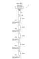
図2は、図1に示される光ファイバケーブル1の概略平面図である。図2に示されるように、光ファイバケーブル1は、幹線ケーブル10、多心光ファイバコード11~14、分岐光ファイバケーブル15-1~15-n(nは、2以上の自然数である)、コネクタ21~24、分岐部材31、及び分岐保護ケース40-1~40-nを有する。ここで、分岐光ファイバケーブル15-1~15-nは互いに同一構造を有し、分岐保護ケース40-1~40-nは互いに同一構造を有する。このため以下では、分岐光ファイバケーブル15-1~15-nのうち光ファイバケーブル15-1の詳細と、分岐保護ケース40-1~40-nのうち分岐保護ケース40-1の詳細とを説明する。 FIG. 2 is a schematic plan view of the
図3は、光ファイバケーブルの要部概略図である。図3においては、分岐保護ケース40-1は省略されている。図3に示されるように、幹線ケーブル10は、光ファイバケーブル1の延在方向においてサーバラック群101と配線盤103との間に位置する主要部分である。幹線ケーブル10の一端は、分岐部材31に収容される。幹線ケーブル10は、複数の光ファイバコード10a(第1光ファイバコード)と、光ファイバコード10aを被覆する補強チューブ10b(第1チューブ)とを有する。 FIG. 3 is a schematic diagram of a main part of an optical fiber cable. In FIG. 3, the branch protection case 40-1 is omitted. As shown in FIG. 3 ,
複数の光ファイバコード10aのそれぞれは、例えば複数の心線を含むコードである。本実施形態では、光ファイバコード10aは、6心コードであるが、これに限られない。複数の光ファイバコード10aのそれぞれの長さは、予め定められてもよいし、互いに同一でもよい。補強チューブ10bは、複数の光ファイバコード10aを束ねると共に保護する部材である。補強チューブ10bの一部は、分岐保護ケース40-1内にて除去される。このため、補強チューブ10bは、少なくとも分岐保護ケース40-1の外部に位置する。 Each of the plurality of
以下では、図3において複数の光ファイバコード10aのうち、補強チューブ10bに収容される幹線を幹線光ファイバコード10cとし、幹線光ファイバコード10cから分岐する支線を分岐光ファイバコード10dとする。幹線光ファイバコード10cの一部は、補強チューブ10bから露出し得る。当該一部は、分岐保護ケース40-1に収容される。分岐光ファイバコード10dは、分岐光ファイバケーブル15-1の一部に相当する。分岐光ファイバコード10dに含まれる心線10e(第1心線)は、分岐光ファイバコード10dの先端部において露出する。当該先端部は、分岐保護ケース40-1に収容される。 In the following, among the plurality of
多心光ファイバコード11~14のそれぞれは、光ファイバケーブル1の延在方向において配線盤103と分岐部材31との間に位置する通信回線である。多心光ファイバコード11~14のそれぞれは、光ファイバコード10aよりも多くの心線を含むコードである。多心光ファイバコード11~14のそれぞれに含まれる心数が、1本の多心光ファイバコードに含まれる光ファイバコード10aの数と、当該光ファイバコード10aに含まれる心数との乗数に等しければよい。本実施形態では、多心光ファイバコード11~14のそれぞれは、24心コードであり、このため4本の光ファイバコード10aを含む。多心光ファイバコード11~14のそれぞれの一端は、分岐部材31に収容される。多心光ファイバコード11の他端は、コネクタ21に収容される。同様に、多心光ファイバコード12~14の他端は、コネクタ22~24にそれぞれ収容される。多心光ファイバコード11~14のそれぞれは、例えば補強チューブによって補強される。 Each of multi-core
コネクタ21~24のそれぞれは、配線盤103に接続されるインターフェースである。コネクタ21~24のそれぞれは、例えばMPOコネクタ(Multi-fiber Push Onコネクタ)である。この場合、コネクタ21に結合される光ファイバの本数(心数)は、多心光ファイバコード11に含まれる光ファイバの本数に相当する。コネクタ22~24も同様である。 Each of
分岐部材31は、多心光ファイバコード11~14から光ファイバコード10aに分岐した箇所を収容する部材である。分岐部材31内には空洞が設けられ、当該空洞に多心光ファイバコード11~14の一端と、光ファイバコード10aの一端とが収容される。分岐部材31内にて、多心光ファイバコード11~14のそれぞれの位置と、光ファイバコード10aのそれぞれの位置とが定められてもよい。分岐部材31内では、多心光ファイバコード11~14に設けられる補強チューブ等が除去されることによって、多心光ファイバコード11~14内の心線が露出する。当該心線は、各光ファイバコード10aの心線として束ねられる。この場合、分岐部材31は、当該心線の保護部材としても機能する。加えて、多心光ファイバコード11~14と光ファイバコード10aとの間には融着接続される部分(融着接続部)が存在しないので、分岐部材31内において光学損失が発生しにくい。分岐部材31内にて、各光ファイバコード10aの位置と、多心光ファイバコード11~14の位置とが定められてもよい。分岐部材31内では、多心光ファイバコード11と光ファイバコード10aとの融着接続部が設けられてもよい。この場合、分岐部材31は、当該融着接続部などの保護部材としても機能する。 The branching
分岐光ファイバケーブル15-1~15-nのそれぞれは、サーバラック群101に接続される通信回線である。図3に示されるように、分岐光ファイバケーブル15-1は、分岐光ファイバコード10dと、分岐幹線ケーブル51と、光ファイバコード52~54(第2光ファイバコード)と、保護部材55と、コネクタ56~58と、スリーブ59とを有する。分岐幹線ケーブル51は、分岐光ファイバケーブル15-1における幹線であり、光ファイバコード10aに対して光接続される。このため、光接続前における分岐幹線ケーブル51は、幹線ケーブル10とは別体の回線である。分岐幹線ケーブル51は、光ファイバコード52~54を収容する補強チューブ51a(第2チューブ)を有する。補強チューブ51aの一部は、分岐保護ケース40-1内にて除去される。このため、補強チューブ51aは、少なくとも分岐保護ケース40-1の外部に位置する。 Each of the branch optical fiber cables 15-1 to 15-n is a communication line connected to the
光ファイバコード52~54のそれぞれは、分岐幹線ケーブル51に収容されるコードであり、分岐光ファイバコード10dに光接続される。光ファイバコード52~54の一端は、分岐保護ケース40-1内に収容される。光ファイバコード52~54の他端は、コネクタ56~58にそれぞれ接続される。光ファイバコード52は、光ファイバコード10aよりも少ない心線52a(第2心線)と、心線52aを被覆するチューブ52bとを有する。光ファイバコード53,54は、光ファイバコード52と同一構造を有する。このため、光ファイバコード53は心線53aとチューブ53bとを有し、光ファイバコード54は心線54aとチューブ54bとを有する。 Each of the
心線52aの一部は、分岐保護ケース40-1内にて補強チューブ51aから露出する。心線53a,54aも同様である。露出した心線52a,53a,54aは、分岐保護ケース40-1内にて心線10eに融着接続される。例えば、互いに整列された状態で固定された心線52a,53a,54aと、整列された状態で固定された心線10eとが、互いに融着接続される。心線52a~54aの合計数は、分岐光ファイバコード10dに含まれる心数の数に相当する。本実施形態では、光ファイバコード52~54のそれぞれには、2本の心線が含まれる。チューブ52bの一部は、保護部材55とコネクタ56との間にて露出する。チューブ52bの別の一部は、分岐保護ケース40-1内にて補強チューブ51aから露出する。チューブ53b,54bも同様である。 A portion of the
保護部材55は、分岐幹線ケーブル51から光ファイバコード52~54に分岐した箇所を保護する部材である。 The
コネクタ56~58のそれぞれは、サーバラック群101に接続されるインターフェースである。コネクタ56~58のそれぞれは、例えばデータリンクコネクタである。コネクタ56に結合される光ファイバの本数(心数)は、光ファイバコード52に含まれる光ファイバの本数に相当する。コネクタ57,58も同様である。 Each of the connectors 56 - 58 is an interface connected to the
スリーブ59は、分岐光ファイバコード10dと光ファイバコード52~54との光接続部を保護する筒状部材である。スリーブ59は、例えば当該光接続部を覆うように成形される樹脂部材である。スリーブ59の外側面59aは、分岐保護ケース40-1に接触し得る。本実施形態では、上記光接続部は、融着接続部である。 The
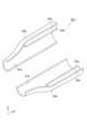
次に、図4(a),(b)、図5及び図6を参照しながら、分岐保護ケース40-1の構造を説明する。図4(a)は、分岐保護ケースの概略斜視図であり、図4(b)は、分岐保護ケースの概略側面図である。図5は、分岐保護ケースの開放状態を示す概略斜視図である。図6は、分岐保護ケースが装着される光ファイバケーブルの要部概略図である。 Next, the structure of the branch protective case 40-1 will be described with reference to FIGS. 4(a), 4(b), 5 and 6. FIG. FIG. 4(a) is a schematic perspective view of a branch protective case, and FIG. 4(b) is a schematic side view of the branch protective case. FIG. 5 is a schematic perspective view showing an open state of the branch protection case. FIG. 6 is a schematic diagram of the essential part of the optical fiber cable to which the branch protection case is attached.
図4(a),(b)、図5及び図6に示されるように、分岐保護ケース40-1は、分岐光ファイバケーブル15-1の分岐位置と、分岐光ファイバケーブル15-1において心線が露出する部分とを保護する部材(光ファイバケーブル用ケース)である。本実施形態では、分岐保護ケース40-1は、心線10eと心線52a,53a,54aとの融着接続部を保護する部材でもある。分岐保護ケース40-1は、例えば樹脂成形体である。分岐保護ケース40-1の少なくとも一部は、弾性を有する。分岐保護ケース40-1は、第1筒部61、第2筒部62、及び第1筒部61と第2筒部62とを仕切る隔壁63を有する本体60を備える。以下では、第1筒部61の長手方向を第1方向Xとし、第1筒部61と第2筒部62とが並ぶ方向を第2方向Yとする。第2方向Yは、第1方向Xに直交する第1筒部61の内径方向の1つに一致する。 As shown in FIGS. 4(a), (b), 5 and 6, the branch protection case 40-1 is provided at the branch position of the branch optical fiber cable 15-1 and at the center of the branch optical fiber cable 15-1. It is a member (optical fiber cable case) that protects the portion where the line is exposed. In this embodiment, the branch protection case 40-1 is also a member that protects the fusion-spliced portions between the
本体60は、第1筒部61の一部分61a、第2筒部62の一部分62a、及び隔壁63の一部分63aを画成する第1本体部60aと、第1筒部61の他部分61b、第2筒部62の他部分62b、及び隔壁63の他部分63bを画成する第2本体部60bとの組合せ構造体である。第1本体部60aと第2本体部60bとは、ヒンジなどの連結部60c,60dによって互いに回動可能に連結される。第1本体部60aと第2本体部60bとの大部分もしくは全てが互いに分離されるとき、分岐保護ケース40-1が開放された状態(開放状態)となる。開放状態において、幹線ケーブル10の一部と、分岐光ファイバケーブル15-1の一部とが、第1本体部60aもしくは第2本体部60bに収容される。その後、第1本体部60aと第2本体部60bとが連結された状態(連結状態)になることによって、分岐保護ケース40-1が幹線ケーブル10及び分岐光ファイバケーブル15-1に装着される。図示しないが、第1本体部60aと第2本体部60bとの少なくとも一方には、上記連結状態を維持する機構が設けられる。 The
第1筒部61は、光ファイバケーブル1の幹線を保護する部分であり、第1方向Xに延在すると共に円筒形状を有する。第1方向Xにおける第1筒部61の一端61cは、第1方向Xにおける本体60の一端に相当する開口端である。第1方向Xにおける第1筒部61の他端61dは、第1方向Xにおける本体60の他端に相当する開口端である。第1筒部61の内径D1は、幹線ケーブル10の太さ以上であればよい。上記連結状態における分岐保護ケース40-1と幹線ケーブル10とのがたつき防止の観点から、第1筒部61の内径D1は、例えば、幹線ケーブル10の太さの1.05倍以下である。上記連結状態においては、幹線ケーブル10が第1筒部61を通線する。なお、幹線ケーブル10の少なくとも一部が第1筒部61に収容されるとき、幹線ケーブル10が第1筒部61を通線するとみなすことができる。上述したように、幹線光ファイバコード10cのうち補強チューブ10bから露出する一部は、分岐保護ケース40-1に収容される。このため上記連結状態においては、幹線光ファイバコード10cが第1筒部61を通線するとみなせる。本実施形態では、第1筒部61の一端61c及びその近傍と、第1筒部61の他端61d及びその近傍には、補強チューブ10bが存在している。 The first
第2筒部62は、光ファイバケーブル1の支線を保護する部分であり、第2方向Yにおいて第1筒部61に隣接している。第2筒部62は、主筒部71、及び主筒部71と第1筒部61とをつなぐ接続筒部72を有する。主筒部71は、第1方向Xに延在すると共に円筒形状を有する部分である。接続筒部72は、主筒部71の内部空間と、第1筒部61の内部空間との両方に連通する部分である。接続筒部72が設けられることによって、第2筒部62の内部空間は、第1筒部61の内部空間に連通している。第1方向Xにおける第2筒部62の一端62cは、接続筒部72に含まれると共に第1筒部61の内部空間に連通する開口端である。一端62cは、第1方向Xにおける第1筒部61の一端61cと他端61dとの間に位置する。第1方向Xにおける第2筒部62の他端62dは、主筒部71に含まれる開口端であり、第1方向Xにおいて第2筒部62の一端62cよりも第1筒部61の他端61dの近くに位置する。本実施形態では、第1方向Xにおいて、第1筒部61の他端61dの位置と、第2筒部62の他端62dの位置とは、互いに揃っている。 The second
第2筒部62の内径D2は、分岐光ファイバケーブル15-1の太さ以上であればよく、このため、第1筒部61の内径D1は内径D2よりも大きい。上記連結状態においては、分岐光ファイバケーブル15-1が第2筒部62を通線する。なお、分岐光ファイバケーブル15-1に含まれる光ファイバコード52~54の一部は、第2筒部62内にて補強チューブ51aから露出し、当該一部は第2筒部62に収容される。このため、光ファイバコード52~54は、分岐保護ケース40-1の第2筒部62を通線するとみなすことができる。上述したように、分岐光ファイバコード10dは、分岐保護ケース40-1に収容される。このため上記連結状態においては、分岐光ファイバコード10dが第2筒部62を通線するとみなせる。 The inner diameter D2 of the second
本実施形態では、第2筒部62の一端62c及びその近傍には分岐光ファイバコード10dが存在し、第2筒部62の他端62d及びその近傍には分岐幹線ケーブル51が存在する。第2筒部62の一端62cと他端62dとの間には、露出した心線10e,52a,53a,54a、分岐光ファイバコード10dと光ファイバコード52~54との融着接続部、及び当該融着接続部を保護するスリーブ59が存在する。 In this embodiment, the branch
第2筒部62の内壁62eには、第1方向Xにおける第2筒部62の一端62cと他端62dとの間に位置する複数の凸部62fが設けられる。凸部62fは、第2筒部62の中心軸に向かって突出するリブであり、弾性を有する。凸部62fは、第2筒部62の一部としてみなされる。このため、第2筒部62において凸部62fが設けられる領域は、他の領域よりも小さい内径である縮径領域である。当該縮径領域の内径は、スリーブ59の外径と同一もしくは実質的に同一である。凸部62fは、例えば、第1方向Xに沿って並んで設けられる。また、第1方向Xから見て、凸部62fは、内壁62eの周方向に沿って並んで設けられるが、これに限られない。第1方向Xから見て、凸部62fは、環形状を有してもよい。第2筒部62に収容される分岐光ファイバケーブル15-1の破損防止の観点から、凸部62fの先端は、丸まっている。 An
スリーブ59の外側面59aは、第2筒部62の一部である凸部62fに挟持される。これにより、第2筒部62内におけるスリーブ59の移動が凸部62fによって規制される。本実施形態では、第1方向Xにおけるスリーブ59の一端部と他端部との両方が、凸部62fによって挟持される。 An
隔壁63は、第1筒部61と第2筒部62を仕切る部材であり、第1方向Xにおいて第2筒部62の一端62cから第2筒部62の他端62dまで延在する。このため、第1筒部61の内部空間と、第2筒部62に含まれる主筒部71の内部空間とは、互いに分離される。隔壁63の一部は第1筒部61の内壁の一部として機能し、隔壁63の別の一部は第2筒部62の内壁62eの一部として機能する。本実施形態では、第1方向Xにおける隔壁63の一端は第2筒部62の一端62cの一部として機能し、第1方向Xにおける隔壁63の他端は第2筒部62の他端62dの一部に加えて、第1筒部61の他端61dの一部として機能する。 The
図6に示されるように、幹線ケーブル10及び分岐保護ケース40-1には、第1熱収縮チューブ81と、第2熱収縮チューブ82とが装着される。図6においては、第1熱収縮チューブ81と、第2熱収縮チューブ82との断面図が示される。第1熱収縮チューブ81と、第2熱収縮チューブ82とのそれぞれは、光ファイバケーブル1における分岐保護ケース40-1の位置を固定する樹脂部材である。本実施形態では、第1熱収縮チューブ81と、第2熱収縮チューブ82とのそれぞれは、円筒形状を有すると共に、熱収縮性を示す部材(熱収縮性部材)である。熱収縮性部材は、例えば加熱により収縮する特性を有する部材である。装着性の観点から、第1熱収縮チューブ81と、第2熱収縮チューブ82とのそれぞれには、スリットが設けられてもよい。この場合、第1熱収縮チューブ81と、第2熱収縮チューブ82とのそれぞれは、断面C字形状を有してもよい。 As shown in FIG. 6, a first heat-
第1熱収縮チューブ81は、第1筒部61の一端61cを囲う位置に設けられる。第1熱収縮チューブ81の内径は、第1方向Xにおける本体60の一端以上であればよい。第1熱収縮チューブ81の一部81aは、第1方向Xにおいて第1筒部61から遠ざかるように延在し、幹線ケーブル10の一部を囲う。換言すると、一部81aは、第1方向Xにおいて第1筒部61の一端61cを挟んで他端61dの反対側に位置する。第2熱収縮チューブ82は、第1筒部61の他端61d及び第2筒部62の他端62dを囲う位置に設けられる。第2熱収縮チューブ82の内径は、第1方向Xにおける本体60の他端以上であればよい。第2熱収縮チューブ82の一部82aは、第1方向Xにおいて第1筒部61から遠ざかるように延在し、幹線ケーブル10の別の一部を囲う。換言すると、一部82aは、第1方向Xにおいて第1筒部61の他端61dを挟んで一端61cの反対側に位置する。 The first heat-
光ファイバケーブル1においては、第1熱収縮チューブ81と、第2熱収縮チューブ82とのそれぞれは、熱収縮された状態である。これにより、第1熱収縮チューブ81は、第1筒部61の一端61cと、幹線ケーブル10において一端61cの近傍に位置する部分とに密着する。また、第2熱収縮チューブ82は、第1筒部61の他端61dと、幹線ケーブル10において他端61dの近傍に位置する部分と、第2筒部62の他端62dと、分岐光ファイバケーブル15-1において他端62dの近傍に位置する部分とに密着する。 In the
以上に説明した本実施形態に係る光ファイバケーブル1によれば、第2筒部62の一端62cから第2筒部62の他端62dまで延在する隔壁63が設けられることから、分岐保護ケース40-1内において幹線光ファイバコード10cと分岐光ファイバコード10dとを互いに分離できる。これにより、分岐保護ケース40-1内における幹線光ファイバコード10cと分岐光ファイバコード10dとの干渉を抑制できる。加えて、第2筒部62の一端62cが第1筒部61の内部空間に連通するので、分岐光ファイバコード10dの分岐開始位置を分岐保護ケース40-1によって覆うことができる。これにより、分岐保護ケース40-1によって当該分岐開始位置を良好に保護できるので、幹線光ファイバコード10cから分岐される分岐光ファイバコード10dの破損を抑制できる。 According to the
本実施形態では、接続部は、分岐光ファイバコード10dに含まれる心線10eと、光ファイバコード52~54に含まれる心線52a,53a,54aとの融着接続部である。このため、当該融着接続部を分岐保護ケース40-1によって良好に保護できる。 In this embodiment, the splicing portion is a fusion splicing portion between the
本実施形態では、光ファイバケーブル1は、少なくとも分岐保護ケース40-1の外部に位置し、複数の光ファイバコード10aを被覆する補強チューブ10bと、少なくとも分岐保護ケース40-1の外部に位置し、光ファイバコード52~54を被覆する補強チューブ51aと、第1筒部61の一端61cと、第1筒部61の他端61dと、第2筒部62の他端62dとを少なくとも囲う樹脂部材である第1熱収縮チューブ81及び第2熱収縮チューブ82と、を備え、当該樹脂部材は、分岐保護ケース40-1の少なくとも一部と、補強チューブ10bの一部と、補強チューブ51aの一部とに密着する。この場合、樹脂部材によって、光ファイバケーブル1における分岐保護ケース40-1のがたつきを抑制できる。 In this embodiment, the
本実施形態では、光ファイバケーブル1は、上記接続部を覆うスリーブ59を備え、スリーブ59の外側面59aは、第2筒部62に挟持される。また、第2筒部62の内壁62eには、第2筒部62の一端62cと他端62dとの間に位置する凸部62fが設けられ、凸部62fは、外側面59aに密着する。このため、第2筒部62内の上記接続部の移動を抑制できるので、当該接続部が破損しにくくなる。 In this embodiment, the
本実施形態では、凸部62fは、弾性を有する。このため、分岐光ファイバケーブル15-1において凸部62fに接触される部分の損傷を抑制できる。 In this embodiment, the
本実施形態では、第1筒部61の一端61cを囲う第1熱収縮チューブ81と、第1筒部61の他端61d及び第2筒部62の他端62dを囲う第2熱収縮チューブ82とが設けられ、第1熱収縮チューブ81の一部81aと、第2熱収縮チューブ82の一部82aとのそれぞれは、第1方向Xにおいて第1筒部61から遠ざかるように延在し、第1熱収縮チューブ81は、第1筒部61の一端61cと、幹線ケーブル10において一端61cの近傍に位置する部分とに密着する。また、第2熱収縮チューブ82は、第1筒部61の他端61dと、幹線ケーブル10において他端61dの近傍に位置する部分と、第2筒部62の他端62dと、分岐光ファイバケーブル15-1において他端62dの近傍に位置する部分とに密着する。このため、第1熱収縮チューブ81及び第2熱収縮チューブ82によって、光ファイバケーブル1に対する分岐保護ケース40-1のがたつきを抑制できる。 In this embodiment, a first heat-
本実施形態では、分岐保護ケース40-1は、第1筒部61、第2筒部62、及び隔壁63を有する本体60を備え、本体60は、第1筒部61の一部分61a、第2筒部62の一部分62a、及び隔壁63の一部分63aを画成する第1本体部60aと、第1筒部61の他部分61b、第2筒部62の他部分62b、及び隔壁63の他部分63bを画成する第2本体部60bとの組合せ構造体である。このため、幹線ケーブル10と分岐光ファイバケーブル15-1とを分岐保護ケース40-1に収容しやすい。 In this embodiment, the branch protection case 40-1 includes a
本実施形態では、分岐保護ケース40-1は、第1本体部60aと第2本体部60bとを連結する連結部60c、60dを備える。このため、第1本体部60aと第2本体部60bとを容易に組立できる。加えて、第1本体部60aと第2本体部60bとのいずれかの紛失などを抑制できる。 In this embodiment, the branch protective case 40-1 includes connecting
本開示に係る分岐保護ケース及びそれを備える光ファイバケーブルは、上述した実施形態に限られるものではなく、他に様々な変形が可能である。例えば、上記実施形態に含まれる第1本体部と第2本体部とは連結部により互いに連結されるが、これに限られない。図7は、変形例に係る分岐保護ケースを示す概略斜視図である。図7に示されるように、第1本体部60aと第2本体部60bとは、互いに別体でもよい。 The branch protection case and the optical fiber cable including the same according to the present disclosure are not limited to the above-described embodiments, and various other modifications are possible. For example, although the first body portion and the second body portion included in the above embodiment are connected to each other by a connecting portion, the present invention is not limited to this. FIG. 7 is a schematic perspective view showing a branch protection case according to a modification. As shown in FIG. 7, the
上記実施形態では、光ファイバケーブルは、1つの分岐保護ケースに対する樹脂部材として第1熱収縮チューブ及び第2熱収縮チューブを有するが、これに限られない。例えば、上記樹脂部材は、熱収縮性を有さなくてもよい。また、光ファイバケーブルは、第1筒部の一端と、第1筒部の他端と、第2筒部の他端とを少なくとも囲う樹脂部材を備えればよい。例えば、1つの分岐保護ケースに対する樹脂部材は、単一のチューブ、テープなどでもよい。前者の場合、例えば、樹脂部材は、分岐保護ケースと、各ケーブルの補強チューブとを覆って密着する。後者の場合、例えば、樹脂部材は、分岐保護ケースと、各ケーブルの補強チューブとに巻回する巻回体である。なお、1つの分岐保護ケースに対して、2以上のテープが巻回されてもよい。これらの巻回体やテープが熱収縮性を有していてもよい。これらの場合であっても、光ファイバケーブルにおける分岐保護ケースのがたつきが抑制される。 In the above embodiment, the optical fiber cable has the first heat-shrinkable tube and the second heat-shrinkable tube as resin members for one branch protective case, but the present invention is not limited to this. For example, the resin member may not have heat shrinkability. Also, the optical fiber cable may include a resin member surrounding at least one end of the first tubular portion, the other end of the first tubular portion, and the other end of the second tubular portion. For example, the resin member for one branch protective case may be a single tube, tape, or the like. In the former case, for example, the resin member covers and adheres to the branch protective case and the reinforcing tube of each cable. In the latter case, for example, the resin member is a wound body wound around the branch protective case and the reinforcing tube of each cable. Two or more tapes may be wound around one branch protection case. These wound bodies and tapes may have heat shrinkability. Even in these cases, rattling of the branch protection case in the optical fiber cable is suppressed.
上記実施形態では、分岐幹線ケーブルは、上記第2光ファイバコードに対して融着接続されるが、これに限られない。例えば、分岐幹線ケーブルと、上記第2光ファイバコードとは、コネクタなどによって互いに接続されてもよい。いずれの場合であっても、分岐幹線ケーブルと上記第2光ファイバコードとの光接続部は、第2筒部に収容される。 In the above embodiment, the branch trunk cable is fusion-spliced to the second optical fiber cord, but the present invention is not limited to this. For example, the branch trunk cable and the second optical fiber cord may be connected to each other by a connector or the like. In either case, the optical connection portion between the branch trunk cable and the second optical fiber cord is accommodated in the second cylindrical portion.
上記実施形態では、第2筒部の内壁に一体化する凸部が設けられるが、これに限られない。凸部は、第2筒部とは別体でもよい。この場合、凸部は、接着剤等を介して第2筒部の内壁上に固定される。 In the above embodiment, the convex portion is provided to be integrated with the inner wall of the second cylindrical portion, but the present invention is not limited to this. The convex portion may be separate from the second cylindrical portion. In this case, the convex portion is fixed on the inner wall of the second tubular portion via an adhesive or the like.
1~4…光ファイバケーブル
10…幹線ケーブル
10a…光ファイバコード(第1光ファイバコード)
10b…補強チューブ
10c…幹線光ファイバコード
10d…分岐光ファイバコード
10e…心線(第1心線)
11~14…多心光ファイバコード
15-1~15-n…分岐光ファイバケーブル
21~24…コネクタ
31…分岐部材
40-1~40-n…分岐保護ケース
51…分岐幹線ケーブル
51a…補強チューブ
52~54…光ファイバコード(第2光ファイバコード)
52a,53a,54a…心線(第2心線)
52b,53b,54b…チューブ
55…保護部材
56~58…コネクタ
59…スリーブ
59a…外側面
60…本体
60a…第1本体部
60b…第2本体部
60c,60d…連結部
61…第1筒部
61a…一部分
61b…他部分
61c…一端
61d…他端
62…第2筒部
62a…一部分
62b…他部分
62c…一端
62d…他端
62e…内壁
62f…凸部
63…隔壁
63a…一部分
63b…他部分
71…主筒部
72…接続筒部
81…第1熱収縮チューブ
82…第2熱収縮チューブ
100…光通信システム
101,102…サーバラック群
101-1~101-n,102-1~102-n…サーバラック
103,104…配線盤
D1…内径
D2…内径
X…第1方向
Y…第2方向。
1 to 4...
DESCRIPTION OF
11 to 14 Multi-core optical fiber cord 15-1 to 15-n Branch
52a, 53a, 54a... core wire (second core wire)
52b, 53b, 54b...
Claims (13)
Translated fromJapanese前記分岐光ファイバコードに接続される第2光ファイバコードと、
前記複数の第1光ファイバコードの一部、及び前記第2光ファイバコードの一部を覆うケースと、を備え、
前記ケースは、前記幹線光ファイバコードが通線される第1筒部と、前記第1筒部に隣接すると共に前記分岐光ファイバコードが通線される第2筒部と、前記第1筒部及び前記第2筒部を仕切る隔壁と、を有し、
前記分岐光ファイバコードと前記第2光ファイバコードとの光接続部は、前記第2筒部に収容され、
前記第2筒部の一端は、前記第1筒部の一端と他端との間に位置すると共に、前記第1筒部の内部空間に連通し、
前記隔壁は、前記第2筒部の前記一端から前記第2筒部の他端まで延在する、
光ファイバケーブル。a plurality of first optical fiber cords having trunk optical fiber cords and branch optical fiber cords;
a second optical fiber cord connected to the branched optical fiber cord;
a case covering a portion of the plurality of first optical fiber cords and a portion of the second optical fiber cord;
The case includes a first tubular portion through which the trunk optical fiber cord is routed, a second tubular portion adjacent to the first tubular portion and through which the branch optical fiber cord is routed, and the first tubular portion. and a partition wall that partitions the second cylindrical portion,
an optical connection portion between the branched optical fiber cord and the second optical fiber cord is accommodated in the second cylindrical portion,
one end of the second cylindrical portion is positioned between one end and the other end of the first cylindrical portion and communicates with the internal space of the first cylindrical portion;
The partition wall extends from the one end of the second tubular portion to the other end of the second tubular portion,
fiber optic cable.
少なくとも前記ケースの外部に位置し、前記第2光ファイバコードを被覆する第2チューブと、
前記第1筒部の前記一端と、前記第1筒部の前記他端と、前記第2筒部の前記他端とを少なくとも囲う樹脂部材と、をさらに備え、
前記樹脂部材は、前記ケースの少なくとも一部と、前記第1チューブの一部と、前記第2チューブの一部とに密着する、請求項1に記載の光ファイバケーブル。a first tube positioned at least outside the case and covering the plurality of first optical fiber cords;
a second tube positioned outside at least the case and covering the second optical fiber cord;
further comprising a resin member surrounding at least the one end of the first tubular portion, the other end of the first tubular portion, and the other end of the second tubular portion;
2. The optical fiber cable according to claim 1, wherein said resin member adheres to at least a portion of said case, a portion of said first tube, and a portion of said second tube.
前記本体は、
前記第1筒部の一部分、前記第2筒部の一部分、及び前記隔壁の一部分を画成する第1本体部と、
前記第1筒部の他部分、前記第2筒部の他部分、及び前記隔壁の他部分を画成する第2本体部との組合せ構造体である、請求項1から請求項3のいずれか一項に記載の光ファイバケーブル。Further comprising a main body having the first tubular portion, the second tubular portion, and the partition wall,
The body is
a first body portion defining a portion of the first tubular portion, a portion of the second tubular portion, and a portion of the partition wall;
4. The structure according to any one of claims 1 to 3, which is a combined structure with a second body portion defining the other portion of the first tubular portion, the other portion of the second tubular portion, and the other portion of the partition wall. The optical fiber cable according to item 1.
前記スリーブの外側面は、前記第2筒部に挟持される、請求項1から請求項5のいずれか一項に記載の光ファイバケーブル。further comprising a sleeve that covers the optical connection,
The optical fiber cable according to any one of claims 1 to 5, wherein the outer surface of the sleeve is sandwiched between the second cylindrical portions.
前記凸部は、前記外側面に密着する、請求項6に記載の光ファイバケーブル。The inner wall of the second cylindrical portion is provided with a convex portion located between the one end and the other end of the second cylindrical portion,
7. The optical fiber cable according to claim 6, wherein said protrusion is in close contact with said outer surface.
前記第1方向に延在し、前記第1方向に直交する第2方向において前記第1筒部に隣接する第2筒部と、
前記第1筒部及び前記第2筒部を仕切る隔壁と、を備え、
前記第1筒部の内径は、前記第2筒部の内径よりも大きく、
前記第2筒部の一端は、前記第1方向における前記第1筒部の一端と他端との間に位置すると共に、前記第1筒部の内部空間に連通し、
前記第2筒部の他端は、前記第1方向において前記第2筒部の前記一端よりも前記第1筒部の前記他端の近くに位置し、
前記隔壁は、前記第1方向において前記第2筒部の前記一端から前記第2筒部の前記他端まで延在する、
光ファイバケーブル用ケース。a first tubular portion extending in a first direction;
a second tubular portion extending in the first direction and adjacent to the first tubular portion in a second direction orthogonal to the first direction;
a partition wall that partitions the first tubular portion and the second tubular portion;
The inner diameter of the first cylindrical portion is larger than the inner diameter of the second cylindrical portion,
one end of the second cylindrical portion is located between one end and the other end of the first cylindrical portion in the first direction and communicates with the internal space of the first cylindrical portion;
the other end of the second cylindrical portion is positioned closer to the other end of the first cylindrical portion than the one end of the second cylindrical portion in the first direction;
The partition wall extends from the one end of the second tubular portion to the other end of the second tubular portion in the first direction,
Case for fiber optic cable.
前記本体は、
前記第1筒部の一部分、前記第2筒部の一部分、及び前記隔壁の一部分を画成する第1本体部と、
前記第1筒部の他部分、前記第2筒部の他部分、及び前記隔壁の他部分を画成する第2本体部との組合せ構造体である、請求項9から請求項11のいずれか一項に記載の光ファイバケーブル用ケース。Further comprising a main body having the first tubular portion, the second tubular portion, and the partition wall,
The body is
a first body portion defining a portion of the first tubular portion, a portion of the second tubular portion, and a portion of the partition wall;
12. The structure according to any one of claims 9 to 11, which is a combined structure with a second body portion defining the other portion of the first tubular portion, the other portion of the second tubular portion, and the other portion of the partition wall. 1. The optical fiber cable case according to claim 1.
Priority Applications (2)
| Application Number | Priority Date | Filing Date | Title |
|---|---|---|---|
| JP2021197035AJP2023082975A (en) | 2021-12-03 | 2021-12-03 | Optical fiber cable and case for optical fiber cable |
| US18/059,001US12399336B2 (en) | 2021-12-03 | 2022-11-28 | Optical fiber cable with partitioned case for optical fiber cable |
Applications Claiming Priority (1)
| Application Number | Priority Date | Filing Date | Title |
|---|---|---|---|
| JP2021197035AJP2023082975A (en) | 2021-12-03 | 2021-12-03 | Optical fiber cable and case for optical fiber cable |
Publications (1)
| Publication Number | Publication Date |
|---|---|
| JP2023082975Atrue JP2023082975A (en) | 2023-06-15 |
Family
ID=86608486
Family Applications (1)
| Application Number | Title | Priority Date | Filing Date |
|---|---|---|---|
| JP2021197035APendingJP2023082975A (en) | 2021-12-03 | 2021-12-03 | Optical fiber cable and case for optical fiber cable |
Country Status (2)
| Country | Link |
|---|---|
| US (1) | US12399336B2 (en) |
| JP (1) | JP2023082975A (en) |
Families Citing this family (2)
| Publication number | Priority date | Publication date | Assignee | Title |
|---|---|---|---|---|
| JP7726045B2 (en)* | 2021-12-03 | 2025-08-20 | 住友電気工業株式会社 | Optical Communication Systems |
| JP2023082975A (en)* | 2021-12-03 | 2023-06-15 | 住友電気工業株式会社 | Optical fiber cable and case for optical fiber cable |
Citations (6)
| Publication number | Priority date | Publication date | Assignee | Title |
|---|---|---|---|---|
| JP2001116968A (en)* | 1999-08-11 | 2001-04-27 | Toyokuni Electric Cable Co Ltd | Optical communication trunk cable and branching tool for optical communication trunk cable |
| US20020064364A1 (en)* | 2000-11-29 | 2002-05-30 | Battey Jennifer A. | Apparatus and method for splitting optical fibers |
| JP2003295019A (en)* | 2002-04-05 | 2003-10-15 | Hitachi Cable Ltd | Branch of optical fiber cable and its branch part |
| JP2005043406A (en)* | 2003-07-22 | 2005-02-17 | Mitsubishi Cable Ind Ltd | Optical fiber junction box |
| JP2012053131A (en)* | 2010-08-31 | 2012-03-15 | Furukawa Electric Co Ltd:The | Optical fiber closure and optical fiber tray |
| CN105629405A (en)* | 2015-03-03 | 2016-06-01 | 韩国Nwc公司 | FTTH household terminal box and optical signal transmission apparatus including the same |
Family Cites Families (42)
| Publication number | Priority date | Publication date | Assignee | Title |
|---|---|---|---|---|
| US5125060A (en)* | 1991-04-05 | 1992-06-23 | Alcatel Na Cable Systems, Inc. | Fiber optic cable having spliceless fiber branch and method of making |
| JP4100834B2 (en) | 1999-08-11 | 2008-06-11 | トヨクニ電線株式会社 | Optical communication trunk cable and branching device for optical communication trunk cable |
| JP4136244B2 (en) | 2000-01-18 | 2008-08-20 | トヨクニ電線株式会社 | Optical communication trunk cable |
| EP1267192B1 (en)* | 2001-06-15 | 2009-02-18 | Prysmian Cables & Systems Limited | Connecting optical fibres |
| JP4080431B2 (en) | 2004-01-21 | 2008-04-23 | トヨクニ電線株式会社 | Light micro box |
| US7127143B2 (en) | 2004-05-24 | 2006-10-24 | Corning Cable Systems Llc | Distribution cable assembly having overmolded mid-span access location |
| US7266274B2 (en)* | 2004-11-03 | 2007-09-04 | Corning Cable Systems Llc | Pre-connectorized fiber optic distribution cable having overmolded access location |
| US7277614B2 (en)* | 2004-12-03 | 2007-10-02 | Corning Cable Systems Llc | Tether assembly having individual connector ports |
| WO2006113810A2 (en)* | 2005-04-19 | 2006-10-26 | Adc Telecommunications, Inc. | Fiber breakout with integral connector |
| US7422378B2 (en)* | 2006-03-09 | 2008-09-09 | Adc Telecommunications, Inc. | Fiber optic cable breakout configuration with excess fiber length |
| US7346243B2 (en) | 2006-05-11 | 2008-03-18 | Corning Cable Systems Llc | Methods for manufacturing fiber optic distribution cables |
| US7693374B2 (en) | 2006-05-11 | 2010-04-06 | Corning Cable Systems Llc | Tools and methods for manufacturing fiber optic distribution cables |
| US8582938B2 (en) | 2006-05-11 | 2013-11-12 | Corning Cable Systems Llc | Fiber optic distribution cables and structures therefore |
| US7840109B2 (en)* | 2006-08-14 | 2010-11-23 | Adc Telecommunications, Inc. | Factory spliced cable assembly |
| WO2008021253A2 (en)* | 2006-08-14 | 2008-02-21 | Adc Telecommunications, Inc. | Factory spliced cable assembly |
| US7532799B2 (en)* | 2007-04-12 | 2009-05-12 | Adc Telecommunications | Fiber optic telecommunications cable assembly |
| US7769261B2 (en)* | 2007-09-05 | 2010-08-03 | Adc Telecommunications, Inc. | Fiber optic distribution cable |
| EP2216662B1 (en)* | 2009-02-10 | 2013-09-18 | Tyco Electronics Raychem BVBA | Splice protection device for optical splices and optical fibre cable assembly incorporating same |
| EP3018512A1 (en) | 2014-11-05 | 2016-05-11 | Corning Optical Communications LLC | Bi-directional data center architectures employing a jacketless trunk cable |
| US9658409B2 (en)* | 2015-03-03 | 2017-05-23 | Senko Advanced Components, Inc. | Optical fiber connector with changeable polarity |
| WO2017110114A1 (en)* | 2015-12-25 | 2017-06-29 | 株式会社フジクラ | Optical fiber cable branching member and optical fiber cable branching structure |
| AU2017224629A1 (en)* | 2016-02-23 | 2018-07-12 | Sumitomo Electric Industries, Ltd. | Intermittent connection type optical fiber ribbon, manufacturing method for intermittent connection type optical fiber ribbon, optical fiber cable and optical fiber cord |
| EP3446166A4 (en)* | 2016-04-18 | 2019-11-20 | Corning Optical Communications LLC | Optical fiber distribution system with connectorized tether |
| JP6412898B2 (en)* | 2016-05-31 | 2018-10-24 | 株式会社フジクラ | Optical fiber cable branch structure |
| US10712519B2 (en)* | 2017-06-28 | 2020-07-14 | Corning Research & Development Corporation | High fiber count pre-terminated optical distribution assembly |
| US10107980B1 (en)* | 2017-12-08 | 2018-10-23 | Ofs Fitel, Llc | Optical fiber cable with rollable ribbons contained in a central tube without intended stranding |
| CA3030399A1 (en)* | 2018-01-16 | 2019-07-16 | Belden Canada Inc. | Fiber optic cassette system with reversible cassettes |
| MX2020010133A (en)* | 2018-03-29 | 2020-10-19 | Corning Res & Dev Corp | Pre-mold assembly for branched optical cable and related method. |
| EP3956704A4 (en)* | 2019-04-16 | 2023-01-11 | Corning Research & Development Corporation | PRE-TERMINATED CABLE ASSEMBLIES FOR INDOOR/OUTDOOR/DATA CENTER APPLICATIONS |
| US11681101B2 (en)* | 2019-10-17 | 2023-06-20 | CommScope Technologies, LLC | Reworkable splice module |
| US11624875B2 (en)* | 2020-02-10 | 2023-04-11 | Senko Advanced Components, Inc. | Fiber optic connector with dust shutter and orienting guide |
| JP6989163B2 (en)* | 2020-03-30 | 2022-01-05 | Necプラットフォームズ株式会社 | Submarine equipment, how to configure submarine equipment, and submarine cable system |
| JP7434047B2 (en)* | 2020-04-28 | 2024-02-20 | 日本航空電子工業株式会社 | Manufacturing method of plug with built-in optical connector and plug with built-in optical connector |
| US12105339B2 (en)* | 2021-06-04 | 2024-10-01 | Sumitomo Electric Industries, Ltd. | Wiring module, frame body for wiring module, and forming method for forming wiring module |
| US11815723B2 (en)* | 2021-10-26 | 2023-11-14 | Sumitomo Electric Industries, Ltd. | Optical connection structure, optical connector, and optical connecting method |
| JP2023082975A (en)* | 2021-12-03 | 2023-06-15 | 住友電気工業株式会社 | Optical fiber cable and case for optical fiber cable |
| JP7726045B2 (en)* | 2021-12-03 | 2025-08-20 | 住友電気工業株式会社 | Optical Communication Systems |
| JP2023082955A (en)* | 2021-12-03 | 2023-06-15 | 住友電気工業株式会社 | fiber optic cable |
| JP7300770B1 (en)* | 2022-03-31 | 2023-06-30 | 株式会社精工技研 | Optical fiber cable with optical connector, method for manufacturing optical fiber cable with optical connector, optical connector |
| US11982856B2 (en)* | 2022-05-19 | 2024-05-14 | Eden Ltd | Cable overblowing connector |
| JP2024059240A (en)* | 2022-10-18 | 2024-05-01 | 住友電気工業株式会社 | Optical fiber cable |
| US20250110306A1 (en)* | 2023-10-02 | 2025-04-03 | Jameson, Llc | Method and universal apparatus for optical fiber installation |
- 2021
- 2021-12-03JPJP2021197035Apatent/JP2023082975A/enactivePending
- 2022
- 2022-11-28USUS18/059,001patent/US12399336B2/enactiveActive
Patent Citations (6)
| Publication number | Priority date | Publication date | Assignee | Title |
|---|---|---|---|---|
| JP2001116968A (en)* | 1999-08-11 | 2001-04-27 | Toyokuni Electric Cable Co Ltd | Optical communication trunk cable and branching tool for optical communication trunk cable |
| US20020064364A1 (en)* | 2000-11-29 | 2002-05-30 | Battey Jennifer A. | Apparatus and method for splitting optical fibers |
| JP2003295019A (en)* | 2002-04-05 | 2003-10-15 | Hitachi Cable Ltd | Branch of optical fiber cable and its branch part |
| JP2005043406A (en)* | 2003-07-22 | 2005-02-17 | Mitsubishi Cable Ind Ltd | Optical fiber junction box |
| JP2012053131A (en)* | 2010-08-31 | 2012-03-15 | Furukawa Electric Co Ltd:The | Optical fiber closure and optical fiber tray |
| CN105629405A (en)* | 2015-03-03 | 2016-06-01 | 韩国Nwc公司 | FTTH household terminal box and optical signal transmission apparatus including the same |
Also Published As
| Publication number | Publication date |
|---|---|
| US20230176307A1 (en) | 2023-06-08 |
| US12399336B2 (en) | 2025-08-26 |
Similar Documents
| Publication | Publication Date | Title |
|---|---|---|
| US20130183012A1 (en) | Fan-out kit for a furcation system | |
| US5659655A (en) | Optical ribbon cable fanout boxes | |
| US9052459B2 (en) | Cable assembly and method | |
| US12399336B2 (en) | Optical fiber cable with partitioned case for optical fiber cable | |
| US20090162019A1 (en) | Spliced-on connector system and method, splicer, and connector holder for producing the same | |
| KR102305131B1 (en) | A fiber optic Breakout kit including Fiber cord protection unit | |
| JP2018112607A (en) | Optical fiber cord and optical fiber cord manufacturing method | |
| EP3822679A1 (en) | Preparation of fiber optic cables for duct applications | |
| JP4751212B2 (en) | Optical fiber branch cable, wiring method thereof, and providing method thereof | |
| JP3972203B2 (en) | Optical wiring component and method for manufacturing optical wiring component | |
| JP6015172B2 (en) | Multi-fiber optical connector manufacturing method and multi-fiber optical connector | |
| US20230003941A1 (en) | Fusion spliced fiber optic cable assemblies and breakout kits | |
| EP4220260A1 (en) | Optical fiber cable and cable with connector | |
| US20240126031A1 (en) | Optical fiber cable and optical communication system including the same | |
| JP2003329887A (en) | Optical connector with multi-core optical fiber ribbon and optical connector with multi-core optical fiber cord | |
| US20230176306A1 (en) | Optical fiber cable | |
| JP2001194536A (en) | Optical connection box and optical connection method | |
| JP2010019986A (en) | Closure for optical cable connection | |
| JP2002267881A (en) | Optical fiber branch cable with multi-core optical connector | |
| JP2868705B2 (en) | Extra length processing method and extra length processing structure for optical cable connection | |
| JP2003302558A (en) | Multi-fiber optical connector with optical fiber cord | |
| JP4237079B2 (en) | Optical fiber cable connection method | |
| KR102482600B1 (en) | Field assembled fiber optic Breakout kit | |
| JP3065295U (en) | Optical fiber connection storage tray and optical fiber connection storage unit | |
| JP3899823B2 (en) | Optical tape fiber core branch |
Legal Events
| Date | Code | Title | Description |
|---|---|---|---|
| A621 | Written request for application examination | Free format text:JAPANESE INTERMEDIATE CODE: A621 Effective date:20241021 | |
| A977 | Report on retrieval | Free format text:JAPANESE INTERMEDIATE CODE: A971007 Effective date:20250625 | |
| A131 | Notification of reasons for refusal | Free format text:JAPANESE INTERMEDIATE CODE: A131 Effective date:20250715 |