JP2023067622A - Virtual rest room providing system, virtual rest room providing device, and virtual rest room providing method - Google Patents
Virtual rest room providing system, virtual rest room providing device, and virtual rest room providing methodDownload PDFInfo
- Publication number
- JP2023067622A JP2023067622AJP2021179028AJP2021179028AJP2023067622AJP 2023067622 AJP2023067622 AJP 2023067622AJP 2021179028 AJP2021179028 AJP 2021179028AJP 2021179028 AJP2021179028 AJP 2021179028AJP 2023067622 AJP2023067622 AJP 2023067622A
- Authority
- JP
- Japan
- Prior art keywords
- user
- virtual
- rest room
- unit
- flow line
- Prior art date
- Legal status (The legal status is an assumption and is not a legal conclusion. Google has not performed a legal analysis and makes no representation as to the accuracy of the status listed.)
- Pending
Links
Images


Landscapes
- Management, Administration, Business Operations System, And Electronic Commerce (AREA)
Abstract
Description
Translated fromJapanese本発明は、仮想休憩室提供システム、仮想休憩室提供装置、および仮想休憩室提供方法に関する。 The present invention relates to a virtual rest room providing system, a virtual rest room providing device, and a virtual rest room providing method.
近年、自宅などで、在宅勤務を行う機会が増えている。特許文献1には、在宅で勤務している勤務者のグループであっても、グループ内のインフォーマルコミュニケーションを行うことのできる技術が開示されている。 In recent years, there are more and more opportunities to work from home.
オフィスで勤務をしている場合には、ユーザの座席から離れた場所で、他のユーザと立ち話や雑談でコミュニケーションをとる機会がある。在宅勤務の環境下などにおいても、ユーザが作業する場所から離れて休憩する場合又は休憩するエリアへ移動した場合に、仮想的な休憩室へと自動で案内し、他のユーザとコミュニケーションをとることのできる技術が望まれる。 When working in an office, there is an opportunity to communicate with other users by standing and chatting at a place away from the user's seat. Even in a telecommuting environment, when a user takes a break away from the work place or moves to a rest area, the user is automatically guided to a virtual break room and communicates with other users. A technology that can
本発明は、在宅勤務の環境下で適切にコミュニケーションをとることのできる仮想休憩室提供システム、仮想休憩室提供装置、および仮想休憩室提供方法を提供することを目的とする。 SUMMARY OF THE INVENTION An object of the present invention is to provide a virtual rest room providing system, a virtual rest room providing apparatus, and a virtual rest room providing method that enable appropriate communication in a telecommuting environment.
本発明に係る仮想休憩室提供システムは、位置検出センサのユーザの位置の検出結果に基づいて、前記ユーザがエリア間に設定された動線上を移動したか否かを判定する動線移動検知部と、を備える検知装置と、前記ユーザがエリア間を移動する際の軌跡を示す動線を設定する動線設定部と、前記ユーザが前記動線上を移動したと判定された場合、仮想空間において他のユーザとコミュニケーションをとることが可能な仮想休憩室に接続する仮想休憩室接続部と、前記仮想休憩室に関する情報を取得する仮想休憩室情報取得部と、前記仮想休憩室に関する情報を出力する出力制御部と、を備える端末装置と、を備える。 A system for providing a virtual rest room according to the present invention includes a flow line movement detection unit that determines whether or not the user has moved on a flow line set between areas based on the detection result of the user's position by the position detection sensor. a detection device comprising: a flow line setting unit for setting a flow line indicating a trajectory when the user moves between areas; and when it is determined that the user has moved on the flow line, in the virtual space A virtual rest room connection unit that connects to a virtual rest room that allows communication with other users, a virtual rest room information acquisition unit that acquires information about the virtual rest room, and outputs information about the virtual rest room. and a terminal device including an output control unit.
本発明に係る仮想休憩室提供装置は、ユーザがエリア間を移動する際の軌跡を示す動線を設定する動線設定部と、前記ユーザが前記エリア間に設定された動線上を移動したか否かを判定する位置情報取得部と、前記ユーザが前記動線上を移動したと判定された場合、仮想空間において他のユーザとコミュニケーションをとることが可能な仮想休憩室に接続する仮想休憩室接続部と、前記仮想休憩室に関する情報を取得する仮想休憩室情報取得部と、前記仮想休憩室に関する情報を出力する出力制御部と、を備える。 A virtual resting room providing device according to the present invention includes a flow line setting unit that sets a flow line indicating a trajectory of a user moving between areas, and whether the user has moved on the flow line set between the areas. and a virtual rest room connection that connects to a virtual rest room where communication with other users in the virtual space is possible when it is determined that the user has moved along the line of flow. a virtual rest room information acquisition unit that acquires information about the virtual rest room; and an output control unit that outputs information about the virtual rest room.
本発明に係る仮想休憩室提供方法は、ユーザがエリア間を移動する際の軌跡を示す動線を設定するステップと、位置検出センサのユーザの位置の検出結果に基づいて、前記ユーザがエリア間に設定された動線上を移動したか否かを判定するステップと、前記ユーザが前記動線上を移動したと判定された場合、仮想空間において他のユーザとコミュニケーションをとることが可能な仮想休憩室に接続するステップと、前記仮想休憩室に関する情報を取得する仮想休憩室情報取得部と、前記仮想休憩室に関する情報を出力するステップと、を含む。 A method for providing a virtual rest room according to the present invention comprises the steps of: setting a flow line indicating a trajectory of a user moving between areas; a step of determining whether or not the user has moved on the line of flow set in a virtual rest room where it is possible to communicate with other users in the virtual space when it is determined that the user has moved on the line of flow a virtual rest room information obtaining unit for obtaining information about the virtual rest room; and a step of outputting information about the virtual rest room.
本発明によれば、在宅勤務の環境下で適切にコミュニケーションをとることができる。 Advantageous Effects of Invention According to the present invention, it is possible to appropriately communicate in a telecommuting environment.
以下、添付図面を参照して、本発明に係る実施形態を詳細に説明する。なお、この実施形態により本発明が限定されるものではなく、また、以下の実施形態において、同一の部位には同一の符号を付することにより重複する説明を省略する。 DETAILED DESCRIPTION OF THE INVENTION Embodiments according to the present invention will be described in detail below with reference to the accompanying drawings. In addition, the present invention is not limited by this embodiment, and in the following embodiments, the same parts are denoted by the same reference numerals, thereby omitting redundant explanations.
[第1実施形態]
図1を用いて、第1実施形態に係る仮想休憩室提供システムの構成例を説明する。図1は、第1実施形態に係る仮想休憩室提供システムの構成例を示す図である。[First embodiment]
A configuration example of the virtual lounge providing system according to the first embodiment will be described with reference to FIG. FIG. 1 is a diagram showing a configuration example of a virtual lounge providing system according to the first embodiment.
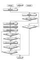
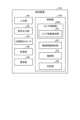
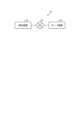
図1に示すように、仮想休憩室提供システム1は、端末装置10と、検知装置12と、サーバ装置14と、を含む。端末装置10と、検知装置12と、サーバ装置14とは、例えば、無線のネットワークNを介して、通信可能に接続されている。仮想休憩室提供システム1は、所定のエリア間に予め設定された動線上をユーザがエリア間を移動した際に、仮想的な休憩室(以下、仮想休憩室)をユーザに提供するシステムである。ユーザは、仮想休憩室において、他のユーザとコミュニケーションをとることができる。 As shown in FIG. 1, the virtual
(端末装置)
図2を用いて、第1実施形態に係る端末装置の構成例を説明する。図2は、第1実施形態に係る端末装置の構成例を示すブロック図である。(Terminal device)
A configuration example of the terminal device according to the first embodiment will be described with reference to FIG. FIG. 2 is a block diagram showing a configuration example of a terminal device according to the first embodiment.
図2に示すように、端末装置10は、入力部20と、表示部22と、音声出力部24と、記憶部26と、GNSS(Global Navigation Satellite System)受信部28と、通信部30と、制御部32と、を備える。端末装置10は、例えば、スマートフォンおよびタブレット端末などの情報処理端末である。 As shown in FIG. 2, the
入力部20は、端末装置10に対する各種の入力操作を受け付ける。入力部20は、受け付けた入力操作に応じた入力信号を制御部32に出力する。入力部20は、例えば、タッチパネル、ボタン、スイッチ、キーボード、マイクなどを含む。入力部20としてタッチパネルが用いられる場合には、入力部20は、表示部22上に配置される。 The
表示部22は、文字及び画像を含む各種の映像を表示する。表示部22は、例えば、液晶ディスプレイ(LCD:Liquid Crystal Display)、有機EL(Electro-Luminescence)などを含むディスプレイである。表示部22は、端末装置10とは異なる装置に設けられていてもよい。例えば、表示部22は、テレビ、およびHMD(Head Mounted Display)、モバイル端末、ウェアラブルデバイスなどであってもよい。端末装置10は、スマートスピーカなどの表示部22を備えない情報処理端末でもよい。 The
音声出力部24は、音声を出力するスピーカである。音声出力部24は、表示部22に表示された画像に対応する音声を出力する。音声出力部24は、他のユーザの音声を出力する。 The audio output unit 24 is a speaker that outputs audio. The audio output section 24 outputs audio corresponding to the image displayed on the
記憶部26は、例えば、後述する動線設定部40が設定した動線に関する情報、制御部32の演算内容、およびプログラム等の情報を記憶する。記憶部26は、例えば、RAM(Random Access Memory)と、ROM(Read Only Memory)のような主記憶装置、HDD(Hard Disk Drive)等の外部記憶装置とのうち、少なくとも1つ含む。 The
GNSS受信部28は、図示しないGNSS衛星から、位置情報を特定するための情報を含むGNSS信号を受信する。GNSS受信部28は、例えば、GNSS受信回路またはGNSS受信装置で実現することができる。 The GNSS receiver 28 receives GNSS signals including information for specifying position information from GNSS satellites (not shown). The GNSS receiver 28 can be realized by, for example, a GNSS receiver circuit or a GNSS receiver.
通信部30は、ネットワークNを介して、外部装置との間で通信を行う。通信部30は、例えば、ネットワークNを介して、検知装置12と通信を行う。通信部30は、例えば、ネットワークNを介して、サーバ装置14と通信を行う。 The
制御部32は、端末装置10の各部を制御する。制御部32は、例えば、CPU(Central Processing Unit)やMPU(Micro Processing Unit)などの情報処理装置と、RAM又はROMなどの記憶装置とを有する。制御部32は、本発明に係る端末装置10の動作を制御するプログラムを実行する。制御部32は、例えば、ASIC(Application Specific Integrated Circuit)やFPGA(Field Programmable Gate Array)等の集積回路により実現されてもよい。制御部32は、ハードウェアと、ソフトウェアとの組み合わせで実現されてもよい。 The
制御部32は、動線設定部40と、仮想休憩室接続部42と、仮想休憩室情報取得部44と、出力制御部46と、位置情報取得部48と、コミュニケーション実行部50とを備える。 The
動線設定部40は、所定のエリア間にユーザが移動する際の軌跡を示す動線を設定する。動線設定部40は、ユーザの操作に従って動線を設定してもよいし、自動で導線を設定してもよい。動線設定部40の詳細は、後述する。 The flow line setting unit 40 sets a flow line indicating a trajectory of a user moving between predetermined areas. The flow line setting unit 40 may set the flow line according to the user's operation, or may automatically set the flow line. Details of the flow line setting unit 40 will be described later.
仮想休憩室接続部42は、仮想空間においてユーザが他のユーザとコミュニケーションをとることが可能な仮想休憩室に接続する。仮想休憩室接続部42は、検知装置12の動線移動検知部82によりユーザが動線上を移動したと判定された場合に、サーバ装置14から提供される仮想休憩室に接続する。 The virtual
仮想休憩室情報取得部44は、サーバ装置14から仮想休憩室に関する情報を取得する。仮想休憩室情報取得部44は、仮想休憩室接続部42が仮想休憩室に接続した場合に、仮想休憩室に関する情報を取得する。仮想休憩室に関する情報には、仮想休憩室の画像および音声に関する情報が含まれる。 The virtual lounge
出力制御部46は、表示部22に各種の情報を表示させる。出力制御部46は、仮想休憩室情報取得部44が取得した仮想休憩室に関する情報を表示部22に表示させる。出力制御部46は、仮想休憩室の画像を表示部22に表示させる。仮想休憩室の画像の詳細は後述する。端末装置10が表示部22を備えない場合、出力制御部46は、音声出力部24に各種の情報を音声出力させる。 The
位置情報取得部48は、GNSS受信部28からGNSS信号を取得する。位置情報取得部48は、GNSS信号に基づいて、ユーザ(端末装置10)の現在の位置情報を算出する。位置情報取得部48は、例えば、ユーザ(端末装置10)の現在の位置情報を地球座標で算出する。 The position
コミュニケーション実行部50は、入力部20が備えるタッチパネル、キーボード、及びマイクなどを用いてユーザ同士のコミュニケーションを実行する。 The communication executing unit 50 executes communication between users using a touch panel, a keyboard, a microphone, and the like included in the
(検知装置)
図3を用いて、第1実施形態に係る検知装置の構成例について説明する。図3は、第1実施形態に係る検知装置の構成例を示すブロック図である。(detection device)
A configuration example of the detection device according to the first embodiment will be described with reference to FIG. FIG. 3 is a block diagram showing a configuration example of the detection device according to the first embodiment.
図3に示すように、検知装置12は、入力部60と、音声出力部62と、位置検出センサ64と、記憶部66と、通信部68と、制御部70と、を備える。検知装置12は、例えば、スマートスピーカで構成されている。 As shown in FIG. 3 , the
入力部60は、検知装置12に対する各種の入力操作を受け付ける。入力部60は、受け付けた入力操作に応じた入力信号を制御部70に出力する。入力部60は、例えば、ボタン、スイッチなどを含む。入力部60は、例えば、ユーザの音声を検出するマイクを含む。 The
音声出力部62は、音声を出力するスピーカである。音声出力部62は、ユーザに確認を促す各種の音声を出力する。 The
位置検出センサ64は、ユーザの位置を検出する。位置検出センサ64は、例えば、ユーザを撮像する単一または複数のカメラで実現される。位置検出センサ64は、例えば、赤外線または超音波のなどの反射波の変化によって人物を検出する人感センサで実現される。位置検出センサ64は、例えば、物体の重さを検出する圧力センサで実現される。 A
記憶部66は、例えば、制御部70の演算内容、およびプログラム等の情報を記憶する。記憶部66は、例えば、RAMと、ROMのような主記憶装置、HDD等の外部記憶装置とのうち、少なくとも1つ含む。 The
通信部68は、ネットワークNを介して、外部装置との間で通信を行う。通信部68は、例えば、ネットワークNを介して、端末装置10と通信を行う。通信部68は、例えば、ネットワークNを介して、サーバ装置14と通信を行う。 The
制御部70は、検知装置12の各部を制御する。制御部70は、例えば、CPUやMPUなどの情報処理装置と、RAM又はROMなどの記憶装置とを有する。制御部70は、本発明に係る検知装置12の動作を制御するプログラムを実行する。制御部70は、例えば、ASICやFPGA等の集積回路により実現されてもよい。制御部70は、ハードウェアと、ソフトウェアとの組み合わせで実現されてもよい。 The
制御部70は、センサ制御部80と、動線移動検知部82と、確認部84と、判定部86と、を備える。 The
センサ制御部80は、位置検出センサ64を制御して、ユーザの位置を検出させる。 The
動線移動検知部82は、予め所定エリア間に設定された動線に沿ったユーザの移動を検知する。動線移動検知部82は、位置検出センサ64のユーザの位置の検出結果に基づいて、ユーザが予め設定された動線上を移動したか否かを検知する。動線移動検知部82の詳細は、後述する。 The flow line
確認部84は、ユーザに対して各種の確認を行う。確認部84は、音声出力部62から音声を出力することで、ユーザに対して各種の確認を行う。確認部84は、ユーザに対して、仮想休憩室に接続するか否かの確認を行う。 The confirmation unit 84 performs various confirmations with the user. The confirmation unit 84 performs various confirmations for the user by outputting audio from the
判定部86は、各種の判定を行う。判定部86は、ユーザの判定を行う。判定部86は、動線上を移動するユーザが予め定められたユーザであるか否かの判定を行う。位置検出センサ64がカメラである場合、判定部86は、カメラで撮像した画像に基づいて、動線上を移動するユーザが予め定められたユーザであるか否かの判定を行う。 The determination unit 86 makes various determinations. The determination unit 86 determines the user. The determination unit 86 determines whether or not the user moving on the flow line is a predetermined user. If the
(サーバ装置)
図4を用いて、第1実施形態に係るサーバ装置に構成例について説明する。図4は、第1実施形態に係るサーバ装置の構成例を示すブロック図である。(Server device)
A configuration example of the server device according to the first embodiment will be described with reference to FIG. FIG. 4 is a block diagram illustrating a configuration example of a server device according to the first embodiment;
図4に示すように、サーバ装置14は、記憶部90と、通信部92と、制御部94と、を備える。サーバ装置14は、端末装置10、検知装置12とからは、離れた場所に配置される。サーバ装置14は、PC(Personal Computer)などの情報端末である。サーバ装置14は、ユーザに対して仮想休憩室を提供する処理を行う。 As shown in FIG. 4 , the server device 14 includes a
記憶部90は、例えば、制御部94の演算内容、およびプログラム等の情報を記憶する。記憶部90は、例えば、RAMと、ROMのような主記憶装置、HDD等の外部記憶装置とのうち、少なくとも1つ含む。 The
記憶部90は、仮想休憩室に関する情報を記憶している。仮想休憩室に関する情報には、仮想休憩室を特定するための情報、仮想休憩室に入室しているユーザの人数に関する情報、ユーザに関する情報が含まれる。仮想休憩室に関する情報には、例えば、仮想休憩室の画像と音声などの情報が含まれてもよい。記憶部90は、仮想休憩室を利用するユーザに関する情報を記憶している。ユーザに関する情報には、ユーザを一意に識別するための識別情報が含まれる。ユーザに関する情報とは例えば、氏名、座席、アイコン画像、及び接続先情報などである。 The
通信部92は、ネットワークNを介して、外部装置との間で通信を行う。通信部92は、例えば、ネットワークNを介して、端末装置10と通信を行う。通信部92は、例えば、ネットワークNを介して、検知装置12と通信を行う。 The
制御部94は、サーバ装置14の各部を制御する。制御部94は、例えば、CPUやMPUなどの情報処理装置と、RAM又はROMなどの記憶装置とを有する。制御部94は、本発明に係るサーバ装置14の動作を制御するプログラムを実行する。制御部94は、例えば、ASICやFPGA等の集積回路により実現されてもよい。制御部94は、ハードウェアと、ソフトウェアとの組み合わせで実現されてもよい。 The
制御部94は、仮想休憩室管理部100を備える。 The
仮想休憩室管理部100は、仮想休憩室を管理する。仮想休憩室管理部100は、仮想休憩室に関する各種の処理を実行する。仮想休憩室管理部100は、端末装置10に対して仮想休憩室を提供する。 The virtual rest room management unit 100 manages the virtual rest room. The virtual rest room management unit 100 executes various processes related to the virtual rest room. The virtual lounge management unit 100 provides the
(仮想休憩室提供システムの処理内容)
図5を用いて、第1実施形態に係る仮想休憩室提供システムの処理内容について説明する。図5は、第1実施形態に係る仮想休憩室提供システムの処理の流れを示すフローチャートである。(Processing details of the virtual break room provision system)
Processing contents of the virtual lounge providing system according to the first embodiment will be described with reference to FIG. FIG. 5 is a flow chart showing the processing flow of the virtual lounge providing system according to the first embodiment.
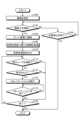
図5に示す処理は、ユーザが予め設定した動線上を移動した場合に、仮想休憩室を提供する場合の処理を示している。 The processing shown in FIG. 5 is processing in the case of providing a virtual lounge when the user moves along a preset flow line.
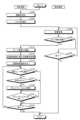
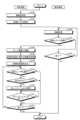
端末装置10は、ユーザがエリア間を移動する際の経路を示す動線を設定する(ステップS10)。具体的には、動線設定部40は、ユーザが入力部20に入力した入力操作に従って、動線を設定する。動線設定部40は、見取り図などに基づいて、自動で設定してもよい。図6と、図7とは、第1実施形態に係る動線を設定する方法の一例を説明するための図である。 The
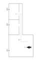
図6は、ユーザUの在宅環境の一例を示す。エリアAR1は、例えば、ユーザUが在宅で仕事をするエリアである。エリアAR2は、例えば、トイレなどである。エリアAR3は、例えば、キッチンなどある。図6に示すように、動線L1は、エリアAR1からエリアAR3の間に設定されている。出力制御部46は、図6に対応する映像データを表示部22に表示させる。ユーザUは、表示部22において、エリアAR1からエリアAR3の間の経路をなぞることで動線L1を設定することができる。動線設定部40は、ユーザUが表示部22において、エリアAR1からエリアAR3の間でなぞった経路を動線L1として設定する。動線設定部40は、表示部22に表示された映像データにおいて、例えばユーザUの休憩時の動線を、機械学習などを用いて予測することにより動線L1を自動で設定してもよい。例えば、図6において、複数の動線が設定されてもよい。 FIG. 6 shows an example of user U's home environment. Area AR1 is, for example, an area where user U works from home. Area AR2 is, for example, a restroom. Area AR3 has, for example, a kitchen. As shown in FIG. 6, the flow line L1 is set between the area AR1 and the area AR3. The
図7は、ユーザUの勤務先の環境の一例を示す。エリアAR11は、例えば、ユーザUの座席がある業務エリアである。エリアAR12は、例えば、会議室である。エリアAR13は、例えば、給湯室である。図7に示すように、動線L2は、エリアAR11からエリアAR13の間に設定されている。動線L2を設定する方法は、図6で示した動線L1を設定する方法と同一なので、説明を省略する。以下では、ユーザUが在宅環境において、動線L1上を移動したか否かを判定する場合を例に説明する。 FIG. 7 shows an example of the environment of the user U's place of work. Area AR11 is, for example, a business area where user U has a seat. Area AR12 is, for example, a conference room. Area AR13 is, for example, a hot water supply room. As shown in FIG. 7, the flow line L2 is set between the area AR11 and the area AR13. The method for setting the line of flow L2 is the same as the method for setting the line of flow L1 shown in FIG. 6, so description thereof will be omitted. A case will be described below as an example where it is determined whether or not the user U has moved on the flow line L1 in the home environment.
検知装置12は、ユーザUが動線L1に沿った移動を検知するための待機状態となる(ステップS12)。そして、ステップS14に進む。 The
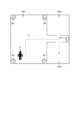
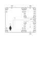
検知装置12は、ユーザUが動線L1上を移動したか否かを判定する(ステップS14)。図8は、第1実施形態に係る動線に沿った移動を検知する方法の一例を説明するための図である。図8に示すように、例えば、エリアAR1の四隅には位置検出センサ64が配置されている。また、位置検出センサ64は、エリアAR1からエリアAR2およびエリアAR3に向かう通路にも配置され得る。位置検出センサ64は、ユーザUを撮像するカメラである。この場合、動線移動検知部82は、例えば、動線L1が設定されている経路を歩いているユーザUが撮像された場合に、ユーザUが動線L1上を移動したと判定する。なお、動線L1が設定されている経路を歩いているユーザUが撮像された場合とは、ユーザの位置と動線L1が厳密に一致することに限定されず、所定の範囲内でずれる場合も含まれてよい。ユーザUが動線L1上を移動したかの判定において、ユーザの歩いている方向は考慮されなくてもよいし、考慮されてもよい。つまり、図8の動線L1の矢印の方向に向かってユーザUが動線L1上を歩いている場合のみ、ユーザUが動線L1上を移動したと判定してもよいし、矢印の反対方向に向かってユーザUが動線L1上を歩いている場合も、ユーザUが動線L1上を移動したと判定してもよい。 The
動線移動検知部82は、ユーザUが歩いた軌跡が動線L1の起点から終点まで一致した場合にユーザUが動線L1上を移動したと判定してもよい。動線移動検知部82は、ユーザUが歩いた軌跡が動線L1と任意の割合で一致した場合にユーザUが動線L1上を移動したと判定してもよい。例えばユーザUが動線L1の半分程度を移動した場合にユーザUが動線L1上を移動したと判定してもよい。 The flow line
位置検出センサ64は、ユーザUを検知する人感センサや、床に配置されている圧力センサであってもよい。この場合、動線移動検知部82は、動線L1が設定されている経路において圧力が検出された場合に、ユーザUが動線L1上を移動したことを検知することができる。ユーザUが動線L1上を移動したことを検知するために配置する位置検出センサ64の数は、任意であってよい。ユーザUが動線L1上を移動したと判定された場合(ステップS14;Yes)、ステップS18に進む。ユーザUが動線L1上を移動したと判定されない場合(ステップS14;No)、ステップS16に進む。 The
ステップS14でNoと判定された場合、検知装置12は、処理を終了するか否かを判定する(ステップS16)。具体的には、検知装置12は、電源をオフする操作を受け付けたり、検知処理を終了する旨の操作を受け付けたりした場合などに、処理を終了すると判定する。処理を終了すると判定された場合(ステップS16;Yes)、図5の処理を終了する。処理を終了すると判定されない場合(ステップS16;No)、ステップS12に進む。 If it is determined No in step S14, the
ステップS14でYesと判定された場合、端末装置10は、仮想休憩室を提供するサーバ装置14に接続する(ステップS18)。具体的には、仮想休憩室接続部42は、通信部30を介して、サーバ装置14に接続する。そして、ステップS20に進む。 If it is determined as Yes in step S14, the
端末装置10は、仮想休憩室情報を取得する(ステップS20)。具体的には、仮想休憩室情報取得部44は、通信部30を介して、サーバ装置14から仮想休憩室に関する情報を取得する。仮想休憩室に関する情報には、仮想休憩室を特定するための情報、仮想休憩室に入室しているユーザの人数に関する情報、ユーザに関する情報が含まれる。仮想休憩室に関する情報には、例えば、仮想休憩室の画像と音声などの情報が含まれてもよい。そして、ステップS22に進む。 The
端末装置10は、仮想休憩室を表示部22に出力する(ステップS22)。具体的には、出力制御部46は、仮想休憩室情報取得部44が取得した仮想休憩室に関する情報に基づいて、仮想休憩室を表示部22に表示させる。端末装置10が表示部22を備えない場合、出力制御部46は、音声出力部24に仮想休憩室に関する情報を音声出力させる。音声出力部24が音声出力する仮想休憩室に関する情報には、仮想休憩室を特定するための情報、仮想休憩室に入室している各ユーザの名前に関する情報、仮想休憩室に入室している各ユーザの状態の情報が含まれる。ここでユーザの状態の情報とは例えば、今どのユーザとユーザとが会話しているかの情報である。 The
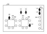
図9を用いて、第1実施形態に係る仮想休憩室の一例について説明する。図9は、第1実施形態に係る仮想休憩室の一例を示す図である。図9に示すように、仮想休憩室200には、複数のテーブル202と、複数のイス204とが、配置されている。仮想休憩室200には、ユーザU1と、ユーザU2と、ユーザU3と、ユーザU4と、ユーザU5と、およびユーザU6とが入室している。ユーザU1は、自身を示すアイコンである。ユーザU2からユーザU6は、他のユーザを示すアイコンである。ユーザU1からユーザU6の上部には、名前が表示されるようにしてもよい。出力制御部46は、仮想休憩室200の接続人数を示す情報を表示してもよい。出力制御部46は、仮想休憩室200に接続している全ユーザの名前の一覧を表示してもよい。 An example of the virtual lounge according to the first embodiment will be described with reference to FIG. FIG. 9 is a diagram showing an example of a virtual lounge according to the first embodiment. As shown in FIG. 9, a plurality of tables 202 and a plurality of
図5に戻る。端末装置10は、ユーザが他のユーザを選択したか否かを判定する(ステップS24)。図10は、第1実施形態に係る他のユーザを選択する方法を説明するための図である。図10に示すように、コミュニケーション実行部50は、例えば、ユーザU2からユーザU6のうちコミュニケーションをとる相手のアイコンを選択したか否かを判定する。ユーザは、例えば、入力部20が表示部22上に配置されたタッチパネルである場合には、ユーザU2からユーザU6のアイコンをタッチすることでコミュニケーションの相手を選択することができる。選択するコミュニケーションの相手は、1人であってもよいし、複数であってもよい。ユーザU2からユーザU6のうち、コミュニケーションの相手を選択する前に、所定のジェスチャを行うようにしてもよい。例えば、図9に示す例では、ユーザU1の左側には、アクションAと、アクションBとの選択ボタンが表示されてよい。この場合、例えば、アクションAを選択すると、ユーザU1がユーザU2に対して手を振る動作を行うようにしてもよい。例えば、アクションBを選択すると、ユーザU1がユーザU2に対して「おーい!」などと声をかける動作を行うようにしてもよい。ユーザが他のユーザを選択したと判定された場合(ステップS24;Yes)、ステップS26に進む。ユーザが他のユーザを選択したと判定されない場合(ステップS24;No)、ステップS32に進む。 Return to FIG. The
ステップS24でYesと判定された場合、端末装置10は、選択した他のユーザからコミュニケーションをとることを許可されたか否かを判定する(ステップS26)。他のユーザからコミュニケーションをとることが許可されたと判定された場合(ステップS26;Yes)、ステップS28に進む。他のユーザからコミュニケーションをとることが許可されたと判定されない場合(ステップS26;No)、ステップS32に進む。 When it is determined as Yes in step S24, the
ステップS26でYesと判定された場合、コミュニケーション実行部50は、コミュニケーションの実行を開始する(ステップS28)。具体的には、図9に示す例でいえば、ユーザU2とコミュニケーションを開始する場合には、その場でコミュニケーションを開始してもよいし、近くのイス204に移動して、コミュニケーションを開始してもよい。例えば、ユーザU5、またはユーザU6とコミュニケーションを開始する場合には、ユーザU5、またはユーザU6の近くのイス204に移動してコミュニケーションを開始してもよいし、ユーザU5、またはユーザU6に近くに来てもらってコミュニケーションを開始してもよい。例えば、ユーザU3と、ユーザU4との2人とコミュニケーションを開始する場合には、相手方の方が多人数なのでユーザU3と、ユーザU4の近くにイス204に移動して、コミュニケーションを開始する。コミュニケーションは、音声を用いた通話であってもよいし、チャットツールを用いたチャットであってもよい。そして、ステップS30に進む。 If determined as Yes in step S26, the communication execution unit 50 starts execution of communication (step S28). Specifically, in the example shown in FIG. 9, when starting communication with user U2, communication may be started on the spot, or the user may move to a
端末装置10は、コミュニケーションを終了したか否かを判定する(ステップS30)。具体的には、コミュニケーション実行部50は、ステップS30で開始したコミュニケーションが終了したか否かを判定する。コミュニケーションを終了したと判定された場合(ステップS30;Yes)、ステップS32に進む。コミュニケーションを終了したと判定されない場合(ステップS30;No)、ステップS30の処理が繰り返される。 The
ステップS24でNo、ステップS26でNo、またはステップS30でYesと判定された場合、端末装置10は、処理を終了するか否かを判定する(ステップS32)。具体的には、端末装置10は、ユーザが仮想休憩室200から退室する場合などに、処理を終了すると判定する。処理を終了すると判定された場合(ステップS32;Yes)、図5の処理を終了する。処理を終了すると判定されない場合(ステップS32;No)、ステップS24に進む。 When determined as No in step S24, No in step S26, or Yes in step S30, the
上述のとおり、第1実施形態は、ユーザが予め設定した動線上を移動したと判定された場合には、自動で仮想休憩室をユーザに対して提供する。ユーザは、仮想休憩室内において、在宅勤務の環境下などであっても、他のユーザと適切にコミュニケーションをとることができる。これにより、第1実施形態は、在宅勤務の環境下などにおける、コミュニケーション不足を解消することができる。 As described above, the first embodiment automatically provides a virtual lounge to the user when it is determined that the user has moved along a preset flow line. The user can appropriately communicate with other users in the virtual rest room even in an environment such as working from home. As a result, the first embodiment can solve the lack of communication in an environment such as working from home.
[第1実施形態の第1変形例]
第1実施形態の第1変形例について説明する。第1実施形態は、動線上を移動したユーザが検知された場合に、仮想休憩室に接続するものとして説明した。第1実施形態の第1変形例は、ユーザに対して仮想休憩室を提供する前に、ユーザが予め登録されたユーザであるか否かを判定する。[First Modification of First Embodiment]
A first modification of the first embodiment will be described. The first embodiment has been described as connecting to the virtual rest room when the user who has moved on the line of flow is detected. A first modification of the first embodiment determines whether the user is a pre-registered user before providing the user with a virtual rest room.
第1実施形態の第1変形例に係る仮想休憩室提供システムの構成は、図1に示す仮想休憩室提供システムの構成と同じなので、説明を省略する。 The configuration of the virtual rest room providing system according to the first modification of the first embodiment is the same as the configuration of the virtual rest room providing system shown in FIG. 1, so the explanation is omitted.
(仮想休憩室提供システムの処理)
図11を用いて、第1実施形態の第1変形例に係る仮想休憩室提供システムの処理内容について説明する。図11は、第1実施形態の第1変形例に係る仮想休憩室提供システムの処理の流れを示すフローチャートである。(Processing of Virtual Rest Room Provision System)
Processing contents of the virtual lounge providing system according to the first modification of the first embodiment will be described with reference to FIG. FIG. 11 is a flow chart showing the processing flow of the virtual lounge providing system according to the first modification of the first embodiment.
ステップS40からステップS44の処理は、それぞれ、図5に示すステップS10からステップS14の処理と同一なので、説明を省略する。 The processing from step S40 to step S44 is the same as the processing from step S10 to step S14 shown in FIG. 5, respectively, so description thereof will be omitted.
ステップS44でYesと判定された場合、検知装置12は、動線上を移動するユーザは所定のユーザであるか否かを判定する(ステップS46)。具体的には、判定部86は、動線上を移動するユーザは仮想休憩室を提供すべき登録されたユーザであるか否かを判定する。この場合、記憶部66には、例えば、仮想休憩室を提供するユーザの顔の画像を含む識別情報が記憶されているとよい。判定部86は、例えば、位置検出センサ64がカメラである場合、位置検出センサ64が休憩エリア内で検出したユーザの顔の画像と、記憶部66に記憶された識別情報を比較することで、動線上を移動するユーザが所定のユーザであるか否かを判定する。動線上を移動するユーザが所定のユーザであると判定された場合(ステップS46;Yes)、ステップS50に進む。動線上を移動するユーザが所定のユーザであると判定されない場合(ステップS46;No)、ステップS48に進む。 When it is determined as Yes in step S44, the
ステップS48からステップS64の処理は、それぞれ、図5に示すステップS16からステップS32の処理と同一なので、説明を省略する。 The processing from step S48 to step S64 is the same as the processing from step S16 to step S32 shown in FIG. 5, respectively, so description thereof will be omitted.
上述のとおり、第1実施形態の第1変形例は、ユーザが予め登録されたユーザであると判定された場合に限って、仮想休憩室をユーザに対して提供する。これにより、第1実施形態の第1変形例は、誤ったユーザに対して仮想休憩室を提供することを防止することができるので、より適切に仮想休憩室を提供することができる。 As described above, the first modification of the first embodiment provides a virtual break room to the user only when it is determined that the user is a pre-registered user. As a result, the first modification of the first embodiment can prevent the virtual rest room from being provided to the wrong user, so that the virtual rest room can be provided more appropriately.
[第1実施形態の第2変形例]
第1実施形態の第2変形例について説明する。第1実施形態は、ユーザが動線上を移動したと判定された場合には、自動で仮想休憩室に接続するものとして説明した。第1実施形態の第2変形例は、ユーザに対して仮想休憩室を提供する前に、仮想休憩室に接続するか否かを確認する。[Second Modification of First Embodiment]
A second modification of the first embodiment will be described. The first embodiment has been described as automatically connecting to the virtual lounge when it is determined that the user has moved along the line of flow. A second modification of the first embodiment confirms whether or not to connect to the virtual rest room before providing the virtual rest room to the user.
第1実施形態の第2変形例に係る仮想休憩室提供システムの構成は、図1に示す仮想休憩室提供システムの構成と同じなので、説明を省略する。 The configuration of the virtual rest room providing system according to the second modification of the first embodiment is the same as the configuration of the virtual rest room providing system shown in FIG. 1, so the explanation is omitted.
(仮想休憩室提供システムの処理)
図12を用いて、第1実施形態の第2変形例に係る仮想休憩室提供システムの処理内容について説明する。図12は、第1実施形態の第2変形例に係る仮想休憩室提供システムの処理の流れを示すフローチャートである。(Processing of Virtual Rest Room Provision System)
Processing contents of the virtual lounge providing system according to the second modification of the first embodiment will be described with reference to FIG. FIG. 12 is a flow chart showing the processing flow of the virtual lounge providing system according to the second modification of the first embodiment.
ステップS70からステップS74の処理は、それぞれ、図5に示すステップS10からステップS14の処理と同一なので、説明を省略する。 The processing from step S70 to step S74 is the same as the processing from step S10 to step S14 shown in FIG. 5, respectively, so description thereof will be omitted.
ステップS14でYesと判定された場合、検知装置12は、仮想休憩室に接続するか否かをユーザに確認する(ステップS76)。図13は、第1実施形態の第2変形例に係る仮想休憩室に接続するか否かを確認する方法を説明するための図である。確認部84は、例えば、音声出力部62から「仮想休憩室に接続しますか?」といった音声を出力することで、ユーザUに対して仮想休憩室に接続するか否かを確認する。確認部84は、例えば、「仮想休憩室にはX人が接続しています。仮想休憩室に接続しますか?」といったように、仮想休憩室に接続している人数に関する情報を音声出力部62から出力してもよい。確認部84は、例えば、「Aさんが仮想休憩室に接続中です。仮想休憩室に接続しますか?」といったように、友人、同僚、上司などの特定の人物が仮想休憩室に接続中である旨の情報を音声出力部62から出力してよい。在宅環境において、音声出力部62は、複数配置されていてもよい。音声出力部62が複数配置されている場合、ユーザUに一番近い位置にある音声出力部62のみから情報を出力してもよい。そして、ステップS78に進む。 If it is determined as Yes in step S14, the
検知装置12は、仮想休憩室に接続するか否かを判定する(ステップS78)。具体的には、判定部86は、例えば、「はい。仮想休憩室に接続してください。」といったユーザUの音声を入力部60で検出した場合に、仮想休憩室に接続すると判定する。判定部86は、例えば、「いいえ。仮想休憩室に接続しないでください。」といったユーザUの音声を入力部60で検出した場合に、仮想休憩室に接続しないと判定する。ユーザは、ステップS78で出力された各種の情報に基づいて、仮想休憩室に接続するか否かを選択することができる。仮想休憩室に接続すると判定されない場合(ステップS78;No)、ステップS80に進む。仮想休憩室に接続すると判定された場合(ステップS78;Yes)、ステップS82に進む。 The
ステップS80からステップS96の処理は、それぞれ、図5に示すステップS16からステップS32の処理と同一なので、説明を省略する。 The processing from step S80 to step S96 is the same as the processing from step S16 to step S32 shown in FIG. 5, respectively, so description thereof will be omitted.
上述のとおり、第1実施形態の第2変形例は、ユーザが仮想休憩室への接続を望んだ場合に限って、仮想休憩室をユーザに対して提供する。これにより、第1実施形態の第2変形例は、ユーザに対してより適切に仮想休憩室を提供することができる。 As described above, the second modification of the first embodiment provides the user with the virtual rest room only when the user desires to connect to the virtual rest room. As a result, the second modification of the first embodiment can more appropriately provide the user with a virtual rest room.
[第2実施形態]
次に、第2実施形態について説明する。第1実施形態は、ユーザが動線上を移動したと判定された場合には、自動で仮想休憩室に接続するものとして説明した。第2実施形態では、ユーザがエリア間を移動したと判定された場合に、仮想休憩室に接続する処理を実行する。[Second embodiment]
Next, a second embodiment will be described. The first embodiment has been described as automatically connecting to the virtual lounge when it is determined that the user has moved along the line of flow. In the second embodiment, when it is determined that the user has moved between areas, a process of connecting to the virtual lounge is executed.
(端末装置)
図14を用いて、第2実施形態に係る端末装置の構成例を説明する。図14は、第2実施形態に係る端末装置の構成例を示すブロック図である。(Terminal device)
A configuration example of the terminal device according to the second embodiment will be described with reference to FIG. FIG. 14 is a block diagram showing a configuration example of a terminal device according to the second embodiment.
図14に示すように、端末装置10Aは、制御部32Aが動線設定部40Aを備え、動線設定部40Aがエリア役割設定部52を備える点で図2に示す端末装置10と異なる。 As shown in FIG. 14, the terminal device 10A is different from the
エリア役割設定部52は、ユーザに仮想休憩室を提供するエリアを設定する。エリア役割設定部52の詳細は後述する。 The area role setting unit 52 sets an area in which a user is provided with a virtual rest room. Details of the area role setting unit 52 will be described later.
(検知装置)
図15を用いて、第2実施形態に係る検知装置の構成例を説明する。図15は、第2実施形態に係る検知装置の構成例を示すブロック図である。(detection device)
A configuration example of the detection device according to the second embodiment will be described with reference to FIG. 15 . FIG. 15 is a block diagram showing a configuration example of a detection device according to the second embodiment.
図15に示すように、検知装置12Aは、制御部70Aが動線移動検知部82Aを備え、動線移動検知部82Aがエリア移動検知部88を備える点で、図3に示す検知装置12と異なる。 As shown in FIG. 15, the detection device 12A is different from the
エリア移動検知部88は、予め設定されたエリアへのユーザの移動を検知する。エリア移動検知部88は、位置検出センサ64のユーザの位置の検出結果に基づいて、予め設定されたエリアへのユーザの移動を検知する。エリア移動検知部88の詳細は、後述する。 Area movement detection unit 88 detects movement of the user to a preset area. The area movement detection unit 88 detects movement of the user to a preset area based on the detection result of the user's position by the
(仮想休憩室提供システムの処理)
図16を用いて、第2実施形態に係る仮想休憩室提供システムの処理内容について説明する。図16は、第2実施形態に係る仮想休憩室提供システムの処理の流れを示すフローチャートである。(Processing of Virtual Rest Room Provision System)
Processing contents of the virtual lounge providing system according to the second embodiment will be described with reference to FIG. 16 . FIG. 16 is a flow chart showing the processing flow of the virtual lounge providing system according to the second embodiment.
ステップS100の処理は、図5に示すステップS10の処理と同一なので、説明を省略する。なお、本実施形態においてステップS100は省略してもよい。 Since the processing of step S100 is the same as the processing of step S10 shown in FIG. 5, the description thereof is omitted. Note that step S100 may be omitted in this embodiment.
端末装置10Aは、エリアを設定する(ステップS102)。エリア役割設定部52は、ユーザに仮想休憩室を提供するエリアを設定する。エリア役割設定部52は、例えば、在宅環境などにおいて各エリアの役割を設定する。エリア役割設定部52は、例えば、業務を行うエリアとしてリビングを設定する。この場合、リビングが、本実施形態の第1エリアの一種となる。エリア役割設定部52は、例えば、仮想休憩室を提供するエリアとしてキッチンを設定する。この場合、キッチンが、本実施形態の第2エリアの一種となる。この場合、在宅環境の場合、例えば、ユーザがリビングからキッチンへ移動した際には仮想休憩室を提供する移動であると判定される。会社などの在外環境の場合、例えば、リビングにある自席からキッチンへ移動した際には仮想休憩室を提供する移動であると判定する。これにより、同じタイミングで、予め定めたキッチンへ移動するユーザ同士に対して仮想休憩室を提供することができるようになる。そして、ステップS104に進む。 The terminal device 10A sets an area (step S102). The area role setting unit 52 sets an area in which a user is provided with a virtual rest room. The area role setting unit 52 sets the role of each area in, for example, a home environment. The area role setting unit 52 sets, for example, the living room as an area in which business is performed. In this case, the living room is a kind of first area in this embodiment. The area role setting unit 52 sets, for example, the kitchen as an area that provides a virtual lounge. In this case, the kitchen is a kind of second area in this embodiment. In this case, in the home environment, for example, when the user moves from the living room to the kitchen, it is determined that the move provides a virtual lounge. In the case of an overseas environment such as a company, for example, when the user moves from his or her seat in the living room to the kitchen, it is determined that the movement provides a virtual lounge. This makes it possible to provide a virtual rest room to users who move to a predetermined kitchen at the same timing. Then, the process proceeds to step S104.
つまり、エリア役割設定部52は、第1エリアと、第1エリアとは異なる第2エリアとを設定する。第1エリアとはユーザが業務を行うエリアで、在宅環境の場合はリビングやユーザの自室などで、勤務先の環境の場合は業務エリアや会議室などである。第2エリアとはユーザが休憩するための休憩エリアで、在宅環境の場合はキッチンやトイレなどで、勤務先の環境の場合は給湯室などである。エリア役割設定部52は、例えばユーザの業務を行うエリアと休憩エリアとを、機械学習などを用いて予測することにより第1エリアと第2エリアとを自動で設定してもよい。 That is, the area role setting unit 52 sets the first area and the second area different from the first area. The first area is an area where the user works, such as the living room or the user's own room in the case of the home environment, and the work area or conference room in the case of the office environment. The second area is a rest area for the user to take a rest, such as the kitchen and toilet in the case of the home environment, and the hot water supply room in the case of the office environment. The area role setting unit 52 may automatically set the first area and the second area by predicting, for example, the user's work area and rest area using machine learning or the like.
ステップS104の処理は、図5に示すステップS12の処理と同一なので、説明を省略する。 Since the processing of step S104 is the same as the processing of step S12 shown in FIG. 5, the description thereof is omitted.
検知装置12は、ユーザUがエリア間を移動したか否かを判定する(ステップS106)。図17は、第2実施形態に係るエリア間の移動を検知する方法の一例を説明するための図である。図17に示すように、例えば、エリアAR1、エリアAR2、およびエリアAR3の四隅には位置検出センサ64が配置されている。また、位置検出センサ64は、エリアAR1からエリアAR2およびエリアAR3に向かう通路にも配置され得る。位置検出センサ64は、ユーザUを撮像するカメラである。この場合、エリア移動検知部88は、エリアAR1がリビングで、エリアAR3がキッチンである場合には、ユーザUがエリアAR1を退出してエリアAR3に進入した時点をカメラの撮像結果に基づいて検知する。位置検出センサ64が人感センサや圧力センサである場合には、各エリアの入口に位置検出センサ64を配置し、エリア移動検知部88は、各エリアの入口における位置検出センサ64の検出結果に基づいて、ユーザUのエリアの移動を検知してもよい。ユーザUがエリア間を移動したと判定された場合(ステップS106;Yes)、ステップS110に進む。ユーザUがエリア間を移動したと判定されない場合(ステップS106;No)、ステップS108に進む。 The
つまり、エリア移動検知部88は、ユーザUが第1エリアから第2エリアへ移動したか否かを検知する。より具体的にはエリア移動検知部88は、ユーザUが第1エリアを退出して第2エリアへ進入したか否かを検知する。 That is, the area movement detection unit 88 detects whether or not the user U has moved from the first area to the second area. More specifically, the area movement detection unit 88 detects whether or not the user U has left the first area and entered the second area.
また、エリア移動検知部88はステップS106において、ユーザUが第2エリアから退出したことを検知してユーザUがエリア間を移動したと判定(ステップS106;Yes)し、処理をステップS110に進めてもよい。これにより、ユーザが第2エリアであるキッチンやトイレなどで用事を済ませてから第1エリアであるリビングに戻るときに他のユーザとコミュニケーションをとることができる。 Also, in step S106, the area movement detection unit 88 detects that the user U has left the second area, determines that the user U has moved between areas (step S106; Yes), and advances the process to step S110. may This allows the user to communicate with other users when returning to the living room, which is the first area, after completing errands in the second area, such as the kitchen or the toilet.
ステップS108からステップS124の処理は、それぞれ、図5に示すステップS16からステップS32の処理と同一なので、説明を省略する。 The processing from step S108 to step S124 is the same as the processing from step S16 to step S32 shown in FIG. 5, respectively, so description thereof will be omitted.
上述のとおり、第2実施形態は、ユーザが予め設定したキッチンなどのエリアに移動したと判定された場合には、仮想休憩室をユーザに対して提供する。これにより、ユーザは在宅勤務などにおいて、オフィスなどで同じタイミングでキッチンなどに移動した他のユーザと仮想休憩室でコミュニケーションをとることができるので、在宅勤務の環境下などにおける、コミュニケーション不足を解消することができる。 As described above, the second embodiment provides the user with a virtual rest room when it is determined that the user has moved to a preset area such as the kitchen. As a result, when a user works from home, the user can communicate with another user who has moved to the kitchen at the same time in the office, etc., in a virtual break room. be able to.
[第2実施形態の変形例]
次に、本開示の第2実施形態の変形例について説明する。第2実施形態の変形例は、在宅環境などにおいて、ユーザが休憩するための休憩エリアを設定する。そして、第2実施形態の変形例は、ユーザが休憩エリアに移動したと判定された場合に、ユーザに対して仮想休憩室を提供する処理を実行する。[Modification of Second Embodiment]
Next, a modification of the second embodiment of the present disclosure will be described. A modification of the second embodiment sets a rest area for the user to rest in a home environment or the like. Then, in the modification of the second embodiment, when it is determined that the user has moved to the rest area, the process of providing the virtual rest room to the user is executed.
(仮想休憩室提供システムの処理)
図18を用いて、第2実施形態の変形例に係る仮想休憩室提供システムの処理内容について説明する。図18は、第2実施形態の変形例に係る仮想休憩室提供システムの処理の流れを示すフローチャートである。(Processing of Virtual Rest Room Provision System)
Processing contents of the virtual lounge providing system according to the modification of the second embodiment will be described with reference to FIG. 18 . FIG. 18 is a flow chart showing the processing flow of the virtual lounge providing system according to the modification of the second embodiment.
ステップS130の処理は、図5に示すステップS10の処理と同一なので、説明を省略する。 Since the processing of step S130 is the same as the processing of step S10 shown in FIG. 5, the description thereof is omitted.
端末装置10Aは、休憩エリアを設定する(ステップS132)。エリア役割設定部52は、ユーザが休憩するための休憩エリアを設定する。これにより、同じタイミングで、予め定めた休憩エリアへ移動するユーザ同士に対して仮想休憩室を提供することができるようになる。そして、ステップS134に進む。 The terminal device 10A sets rest areas (step S132). The area role setting unit 52 sets rest areas for the user to rest. This makes it possible to provide a virtual rest room to users moving to a predetermined rest area at the same timing. Then, the process proceeds to step S134.
ステップS134の処理は、図5に示すステップS12の処理と同一なので、説明を省略する。 Since the processing of step S134 is the same as the processing of step S12 shown in FIG. 5, the description thereof is omitted.
検知装置12は、ユーザUが休憩エリアに移動したか否かを判定する(ステップS136)。検知装置12が、ユーザUが休憩エリアに移動したか否かを判定する方法は、図16に示したステップS106の処理と同一なので、説明を省略する。ユーザUが休憩エリアに移動したと判定された場合(ステップS136;Yes)、ステップS140に進む。ユーザUが休憩エリアに移動したと判定されない場合(ステップS136;No)、ステップS138に進む。 The
ステップS138からステップS154の処理は、それぞれ、図5に示すステップS16からステップS32の処理と同一なので、説明を省略する。 The processing from step S138 to step S154 is the same as the processing from step S16 to step S32 shown in FIG. 5, respectively, so description thereof will be omitted.
上述のとおり、第2実施形態の変形例は、ユーザが予め設定した休憩エリアに移動したと判定された場合には、仮想休憩室をユーザに対して提供する。これにより、ユーザは在宅勤務などにおいて、オフィスなどで同じタイミングで休憩している他のユーザと仮想休憩室でコミュニケーションをとることができるので、在宅勤務の環境下などにおける、コミュニケーション不足を解消することができる。 As described above, the modification of the second embodiment provides the user with a virtual rest room when it is determined that the user has moved to a preset rest area. As a result, the user can communicate with other users who are resting at the same time in the office or the like in the virtual rest room when working from home, etc., so that the lack of communication in the environment of working from home can be solved. can be done.
[第3実施形態]
図19を用いて、第3実施形態に係る仮想休憩室提供システムの構成例を説明する。図19は、第3実施形態に係る仮想休憩室提供システムの構成例を示す図である。[Third embodiment]
A configuration example of the virtual lounge providing system according to the third embodiment will be described with reference to FIG. FIG. 19 is a diagram showing a configuration example of a virtual lounge providing system according to the third embodiment.
図19に示すように、仮想休憩室提供システム1Aは、端末装置10と、サーバ装置14と、を含む。仮想休憩室提供システム1Aは、検知装置12を含まない点で、図1に示す仮想休憩室提供システム1と異なる。仮想休憩室提供システム1Aにおける端末装置10の位置情報取得部48は、予め所定エリア間に設定された動線に沿ったユーザの移動を検知する。 As shown in FIG. 19, the virtual rest room providing system 1A includes a
仮想休憩室提供システム1Aは、レストラン、カフェ、および公園などを、仮想休憩室を提供するエリアであると設定する。仮想休憩室提供システム1Aは、ユーザの自宅などから仮想休憩室を提供するエリアへの移動を検知した場合に、ユーザに対して仮想休憩室を提供する。 The virtual lounge provision system 1A sets restaurants, cafes, parks, etc. as areas for providing virtual lounges. The virtual rest room providing system 1A provides a virtual rest room to the user when it detects movement from the user's home or the like to an area where the virtual rest room is provided.
(仮想休憩室提供システムの処理)
図20を用いて、第3実施形態に係る仮想休憩室提供システムの処理内容について説明する。図20は、第3実施形態に係る仮想休憩室提供システムの処理の流れを示すフローチャートである。(Processing of Virtual Rest Room Provision System)
Processing contents of the virtual lounge providing system according to the third embodiment will be described with reference to FIG. FIG. 20 is a flow chart showing the processing flow of the virtual lounge providing system according to the third embodiment.
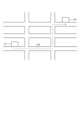
端末装置10(仮想休憩室提供装置)は、動線を設定する(ステップS160)。図21は、第3実施形態に係る動線を設定する方法の一例を説明するための図である。図21は、自宅P1からカフェP2までの地図情報を示す。動線設定部40は、自宅P1からカフェP2までの経路を示す動線L10を設定する。動線設定部40は、自宅P1からカフェP2までの経路について、複数の動線を設定してもよい。そして、ステップS162に進む。 The terminal device 10 (virtual rest room providing device) sets a flow line (step S160). FIG. 21 is a diagram for explaining an example of a method of setting flow lines according to the third embodiment. FIG. 21 shows map information from home P1 to cafe P2. The flow line setting unit 40 sets a flow line L10 indicating a route from home P1 to cafe P2. The flow line setting unit 40 may set a plurality of flow lines for the route from home P1 to cafe P2. Then, the process proceeds to step S162.
端末装置10の位置情報取得部48は、ユーザUが動線上を移動したか否かを判定する(ステップS162)。具体的には、位置情報取得部48は、GNSS受信部28から取得したGNSS信号に基づいて算出されたユーザUの位置情報が、ステップS100で設定された動線L10上である場合に、ユーザUが動線L10上を移動したと判定する。なお、ユーザUの位置情報が、ステップS160で設定された動線L10上である場合とは、位置情報が厳密に一致することに限定されず、所定の範囲内でずれる場合も含まれてよい。ユーザUが動線上を移動したと判定されない場合(ステップS162;No)、ステップS164に進む。ユーザUが動線上を移動したと判定された場合(ステップS162;Yes)、ステップS166に進む。 The position
位置情報取得部48がステップS162においてユーザUの位置情報を取得する方法は、GNSS信号に基づいて算出するのに限らない。例えば、屋外に設置された図示しない監視カメラ等の撮像装置が撮像した画像に基づいて、ユーザUの位置情報を取得してもよい。 The method by which the location
ステップS162でNoと判定された場合、端末装置10は、現在位置の位置検出を終了するか否かを判定する(ステップS164)。具体的には、端末装置10は、電源をオフにする操作を受け付けた場合は、現在位置の位置検出を終了する旨の操作を受け付けた場合に、現在位置の位置検出を終了すると判定する。現在位置の位置検出を終了すると判定された場合(ステップS164;Yes)、図20の処理を終了する。現在位置の位置検出を終了すると判定されない場合(ステップS164;No)、ステップS162に進む。 When determined as No in step S162, the
ステップS166からステップS180の処理は、それぞれ、図5に示すステップS18からステップS32の処理と同一なので、説明を省略する。 The processing from step S166 to step S180 is the same as the processing from step S18 to step S32 shown in FIG. 5, respectively, so description thereof will be omitted.
上述のとおり、第3実施形態は、ユーザが予め設定したカフェなどに移動したと判定された場合には、仮想休憩室をユーザに対して提供する。これにより、第3実施形態は、在宅勤務の環境下などにおける外出時などにおいて、コミュニケーション不足を解消することができる。 As described above, the third embodiment provides the user with a virtual rest room when it is determined that the user has moved to a preset cafe or the like. As a result, the third embodiment can solve the lack of communication when going out in an environment such as working from home.
以上、本発明の実施形態を説明したが、これら実施形態の内容により本発明が限定されるものではない。また、前述した構成要素には、当業者が容易に想定できるもの、実質的に同一のもの、いわゆる均等の範囲のものが含まれる。さらに、前述した構成要素は適宜組み合わせることが可能である。さらに、前述した実施形態の要旨を逸脱しない範囲で構成要素の種々の省略、置換又は変更を行うことができる。 Although the embodiments of the present invention have been described above, the present invention is not limited by the contents of these embodiments. In addition, the components described above include those that can be easily assumed by those skilled in the art, those that are substantially the same, and those within the so-called equivalent range. Furthermore, the components described above can be combined as appropriate. Furthermore, various omissions, replacements, or modifications of components can be made without departing from the gist of the above-described embodiments.
1,1A 仮想休憩室提供システム
10,10A 端末装置
12,12A 検知装置
14 サーバ装置
20,60 入力部
22 表示部
24,62 音声出力部
26,66,90 記憶部
28 GNSS受信部
30,68,92 通信部
32,70,94 制御部
40,40A 動線設定部
42 仮想休憩室接続部
44 仮想休憩室情報取得部
46 出力制御部
48 位置情報取得部
50 コミュニケーション実行部
52 エリア役割設定部
64 位置検出センサ
80 センサ制御部
82,82A 動線移動検知部
84 確認部
86 判定部
88 エリア移動検知部
100 仮想休憩室管理部
200 仮想休憩室
AR1,AR2,AR3 エリア
U ユーザ
L1,L2,L10 動線1, 1A Virtual break
Claims (5)
Translated fromJapanese前記ユーザがエリア間を移動する際の軌跡を示す動線を設定する動線設定部と、
前記ユーザが前記動線上を移動したと判定された場合、仮想空間において他のユーザとコミュニケーションをとることが可能な仮想休憩室に接続する仮想休憩室接続部と、
前記仮想休憩室に関する情報を取得する仮想休憩室情報取得部と、
前記仮想休憩室に関する情報を出力する出力制御部と、を備える端末装置と、
を備える、仮想休憩室提供システム。a detection device comprising: a flow line movement detection unit that determines whether or not the user has moved on a flow line set between areas based on the detection result of the user's position by the position detection sensor;
a flow line setting unit that sets a flow line indicating a trajectory of the user moving between areas;
a virtual rest room connection unit that connects to a virtual rest room in which the user can communicate with other users in the virtual space when it is determined that the user has moved along the line of flow;
a virtual rest room information acquisition unit that acquires information about the virtual rest room;
a terminal device comprising an output control unit that outputs information about the virtual rest room;
A virtual rest room providing system comprising:
前記動線移動検知部は、前記ユーザが前記第1エリアから前記第2エリアへ移動したか否かを検知するエリア移動検知部を備え、
前記仮想休憩室接続部は、前記第1エリアから前記第2エリアへの移動を検知した場合に、前記仮想休憩室に接続する、
請求項1に記載の仮想休憩室提供システム。The flow line setting unit includes an area role setting unit that sets a first area and a second area different from the first area,
The flow line movement detection unit includes an area movement detection unit that detects whether the user has moved from the first area to the second area,
The virtual rest room connection unit connects to the virtual rest room when movement from the first area to the second area is detected.
The virtual rest room providing system according to claim 1.
請求項2に記載の仮想休憩室提供システム。The second area is a rest area for the user to rest,
The virtual rest room providing system according to claim 2.
前記ユーザが前記エリア間に設定された動線上を移動したか否かを判定する位置情報取得部と、
前記ユーザが前記動線上を移動したと判定された場合、仮想空間において他のユーザとコミュニケーションをとることが可能な仮想休憩室に接続する仮想休憩室接続部と、
前記仮想休憩室に関する情報を取得する仮想休憩室情報取得部と、
前記仮想休憩室に関する情報を出力する出力制御部と、
を備える仮想休憩室提供装置。a flow line setting unit for setting a flow line indicating a trajectory when a user moves between areas;
a location information acquisition unit that determines whether or not the user has moved on a flow line set between the areas;
a virtual rest room connection unit that connects to a virtual rest room in which the user can communicate with other users in the virtual space when it is determined that the user has moved along the line of flow;
a virtual rest room information acquisition unit that acquires information about the virtual rest room;
an output control unit that outputs information about the virtual rest room;
A virtual rest room providing device comprising:
位置検出センサのユーザの位置の検出結果に基づいて、前記ユーザがエリア間に設定された動線上を移動したか否かを判定するステップと、
前記ユーザが前記動線上を移動したと判定された場合、仮想空間において他のユーザとコミュニケーションをとることが可能な仮想休憩室に接続するステップと、
前記仮想休憩室に関する情報を取得する仮想休憩室情報取得部と、
前記仮想休憩室に関する情報を出力するステップと、
を含む、仮想休憩室提供方法。a step of setting a flow line indicating a trajectory of a user moving between areas;
a step of determining whether or not the user has moved on a flow line set between areas based on the detection result of the position of the user by the position detection sensor;
When it is determined that the user has moved along the line of flow, connecting to a virtual rest room where communication can be made with other users in the virtual space;
a virtual rest room information acquisition unit that acquires information about the virtual rest room;
outputting information about the virtual break room;
A method of providing a virtual break room, comprising:
Priority Applications (3)
| Application Number | Priority Date | Filing Date | Title |
|---|---|---|---|
| JP2021179028AJP2023067622A (en) | 2021-11-01 | 2021-11-01 | Virtual rest room providing system, virtual rest room providing device, and virtual rest room providing method |
| US17/945,143US11985176B2 (en) | 2021-09-24 | 2022-09-15 | Virtual-break-room providing system, virtual-break-room providing device, and virtual-break-room providing method |
| EP22197080.9AEP4156653B1 (en) | 2021-09-24 | 2022-09-22 | Virtual-break-room providing system, virtual-break-room providing device, and virtual-break-room providing method |
Applications Claiming Priority (1)
| Application Number | Priority Date | Filing Date | Title |
|---|---|---|---|
| JP2021179028AJP2023067622A (en) | 2021-11-01 | 2021-11-01 | Virtual rest room providing system, virtual rest room providing device, and virtual rest room providing method |
Publications (1)
| Publication Number | Publication Date |
|---|---|
| JP2023067622Atrue JP2023067622A (en) | 2023-05-16 |
Family
ID=86326551
Family Applications (1)
| Application Number | Title | Priority Date | Filing Date |
|---|---|---|---|
| JP2021179028APendingJP2023067622A (en) | 2021-09-24 | 2021-11-01 | Virtual rest room providing system, virtual rest room providing device, and virtual rest room providing method |
Country Status (1)
| Country | Link |
|---|---|
| JP (1) | JP2023067622A (en) |
Citations (7)
| Publication number | Priority date | Publication date | Assignee | Title |
|---|---|---|---|---|
| WO2000076154A1 (en)* | 1999-06-02 | 2000-12-14 | Fujitsu Limited | Virtual communication space constructing system corresponding to real world sensing information |
| JP2001160959A (en)* | 1999-12-02 | 2001-06-12 | Canon Inc | Apparatus and method for controlling virtual system and storage medium |
| JP2010183322A (en)* | 2009-02-05 | 2010-08-19 | Mitsubishi Electric Building Techno Service Co Ltd | Equipment controller |
| US20130035114A1 (en)* | 2006-04-07 | 2013-02-07 | Jeffrey Alan Holden | Proximity-related user groups |
| US20190334961A1 (en)* | 2012-10-19 | 2019-10-31 | Sococo, Inc. | Bridging Physical and Virtual Spaces |
| JP2020507797A (en)* | 2016-12-29 | 2020-03-12 | マジック リープ, インコーポレイテッドMagic Leap,Inc. | Automatic control of wearable display device based on external conditions |
| JP2021002289A (en)* | 2019-06-24 | 2021-01-07 | 富士電機株式会社 | Traffic line analyzer and program |
- 2021
- 2021-11-01JPJP2021179028Apatent/JP2023067622A/enactivePending
Patent Citations (7)
| Publication number | Priority date | Publication date | Assignee | Title |
|---|---|---|---|---|
| WO2000076154A1 (en)* | 1999-06-02 | 2000-12-14 | Fujitsu Limited | Virtual communication space constructing system corresponding to real world sensing information |
| JP2001160959A (en)* | 1999-12-02 | 2001-06-12 | Canon Inc | Apparatus and method for controlling virtual system and storage medium |
| US20130035114A1 (en)* | 2006-04-07 | 2013-02-07 | Jeffrey Alan Holden | Proximity-related user groups |
| JP2010183322A (en)* | 2009-02-05 | 2010-08-19 | Mitsubishi Electric Building Techno Service Co Ltd | Equipment controller |
| US20190334961A1 (en)* | 2012-10-19 | 2019-10-31 | Sococo, Inc. | Bridging Physical and Virtual Spaces |
| JP2020507797A (en)* | 2016-12-29 | 2020-03-12 | マジック リープ, インコーポレイテッドMagic Leap,Inc. | Automatic control of wearable display device based on external conditions |
| JP2021002289A (en)* | 2019-06-24 | 2021-01-07 | 富士電機株式会社 | Traffic line analyzer and program |
Similar Documents
| Publication | Publication Date | Title |
|---|---|---|
| US9986206B2 (en) | User experience for conferencing with a touch screen display | |
| CN105683867B (en) | Touch-screen display is configured to meeting | |
| US11461736B2 (en) | Presence status display system and presence status display method | |
| US10245732B2 (en) | Reception system and reception method | |
| KR101573646B1 (en) | Spatial bookmarking | |
| CN109691074A (en) | Image data for enhanced user interaction | |
| CN109416591A (en) | Image data for enhanced user interaction | |
| CN109167871A (en) | For managing the user interface of controllable external equipment | |
| US10748094B2 (en) | Reminder notification system and reminder notification method | |
| US11138862B2 (en) | Systems and methods to electronically indicate whether conference room is in use based on sensor input | |
| JPWO2018087971A1 (en) | MOBILE BODY CONTROL DEVICE AND MOBILE BODY CONTROL PROGRAM | |
| KR20190035373A (en) | Virtual movile device implementing system and control method for the same in mixed reality | |
| US20250182060A1 (en) | Information display device and activity plan display system | |
| US12244770B2 (en) | Conferencing system, server, information processing device and non-transitory recording medium | |
| JP2023067622A (en) | Virtual rest room providing system, virtual rest room providing device, and virtual rest room providing method | |
| US20220405689A1 (en) | Information processing apparatus, information processing method, and program | |
| JP2016010039A (en) | Remote conference system, video processing method, video controller, conference terminal, and program thereof | |
| US11985176B2 (en) | Virtual-break-room providing system, virtual-break-room providing device, and virtual-break-room providing method | |
| JP6701887B2 (en) | Information processing system, information processing method, and program | |
| JP2023047000A (en) | Virtual rest room providing system and virtual rest room providing method | |
| CN115567673A (en) | Video conference processing method, system, electronic device and storage medium | |
| JP2023130822A (en) | Apparatus system, imaging apparatus, and display method | |
| JP5937831B2 (en) | TERMINAL DEVICE, TERMINAL DEVICE CONTROL METHOD, AND TERMINAL DEVICE CONTROL PROGRAM | |
| US20240275625A1 (en) | Information processing device, information processing method, and program | |
| JP2023137823A (en) | Equipment system, information processing method, information processing system, program, and imaging device |
Legal Events
| Date | Code | Title | Description |
|---|---|---|---|
| A621 | Written request for application examination | Free format text:JAPANESE INTERMEDIATE CODE: A621 Effective date:20241031 | |
| A977 | Report on retrieval | Free format text:JAPANESE INTERMEDIATE CODE: A971007 Effective date:20250711 | |
| A131 | Notification of reasons for refusal | Free format text:JAPANESE INTERMEDIATE CODE: A131 Effective date:20250715 | |
| A521 | Request for written amendment filed | Free format text:JAPANESE INTERMEDIATE CODE: A523 Effective date:20250912 | |
| A01 | Written decision to grant a patent or to grant a registration (utility model) | Free format text:JAPANESE INTERMEDIATE CODE: A01 Effective date:20250930 |