JP2023060856A - dental curing light - Google Patents
dental curing lightDownload PDFInfo
- Publication number
- JP2023060856A JP2023060856AJP2023018376AJP2023018376AJP2023060856AJP 2023060856 AJP2023060856 AJP 2023060856AJP 2023018376 AJP2023018376 AJP 2023018376AJP 2023018376 AJP2023018376 AJP 2023018376AJP 2023060856 AJP2023060856 AJP 2023060856A
- Authority
- JP
- Japan
- Prior art keywords
- light
- optical
- light source
- curing
- energy
- Prior art date
- Legal status (The legal status is an assumption and is not a legal conclusion. Google has not performed a legal analysis and makes no representation as to the accuracy of the status listed.)
- Pending
Links
Images


Classifications
- A—HUMAN NECESSITIES
- A61—MEDICAL OR VETERINARY SCIENCE; HYGIENE
- A61C—DENTISTRY; APPARATUS OR METHODS FOR ORAL OR DENTAL HYGIENE
- A61C19/00—Dental auxiliary appliances
- A61C19/003—Apparatus for curing resins by radiation
- A61C19/004—Hand-held apparatus, e.g. guns
- A—HUMAN NECESSITIES
- A61—MEDICAL OR VETERINARY SCIENCE; HYGIENE
- A61C—DENTISTRY; APPARATUS OR METHODS FOR ORAL OR DENTAL HYGIENE
- A61C1/00—Dental machines for boring or cutting ; General features of dental machines or apparatus, e.g. hand-piece design
- A61C1/08—Machine parts specially adapted for dentistry
- A61C1/088—Illuminating devices or attachments
- A—HUMAN NECESSITIES
- A61—MEDICAL OR VETERINARY SCIENCE; HYGIENE
- A61C—DENTISTRY; APPARATUS OR METHODS FOR ORAL OR DENTAL HYGIENE
- A61C19/00—Dental auxiliary appliances
- A61C19/003—Apparatus for curing resins by radiation
Landscapes
- Health & Medical Sciences (AREA)
- Oral & Maxillofacial Surgery (AREA)
- Dentistry (AREA)
- Epidemiology (AREA)
- Life Sciences & Earth Sciences (AREA)
- Animal Behavior & Ethology (AREA)
- General Health & Medical Sciences (AREA)
- Public Health (AREA)
- Veterinary Medicine (AREA)
- Dental Tools And Instruments Or Auxiliary Dental Instruments (AREA)
Abstract
Description
Translated fromJapanese技術分野
本開示は歯科硬化光に関し、より詳細には歯科硬化光からの光の制御されたデリバリーに関する。TECHNICAL FIELD The present disclosure relates to dental curing lights and, more particularly, to controlled delivery of light from dental curing lights.
背景
クラス2修復歯科のために使用される光硬化複合材コンパウンドの導入及び続く市場への浸透に伴い、修復歯科加工の構造品質、自然外観及び寿命に有意な成果がなされた。しかしながら、同時に、新たなカーブが歯科医に投げられた。より古い伝統的なアマルガムフィリングとは異なり、複合材フィリングがうまく配置されそして造形されても、歯科医はなおも終わりではない。コンパウンドを完全に重合させ、そして問題のない配置を確実にしようと試みる努力において、歯科医は所定の波長の強い光でコンパウンドを硬化させる。この機能を達成するために使用された多くの初期の硬化光は、光源としてハロゲンをベースとする白熱ランプを使用した。この技術は単純かつ比較的に安価であるが、少々「パワーハングリー」であり、そしてランプ及び処置されている歯の両方で、高度の廃熱を生じる。歯に実際に送られたエネルギー波長を光学的にフィルターする設計改善は、歯の不必要な加熱を有意に低減した。このことは、ほとんどの修復コンパウンドの相互重合を誘導するために使用される従来の光活性剤が青色光スペクトルの一部のみを使用することから、有用な改善であった。歯にデリバリーされる光のグリーン、レッド及び赤外レッド部分のほとんどをフィルタリングすることにより、歯での「廃熱」にしかならない不必要な波長の多くを排除する方向に進歩がなされた。光硬化複合材を用いた歯科修復のための典型的な硬化時間は20~60秒の間であった。BACKGROUND With the introduction and subsequent market penetration of light curing composite compounds used for Class 2 restorative dentistry, significant gains have been made in the structural quality, natural appearance and longevity of restorative fabrication. At the same time, however, a new curve was thrown at the dentist. Unlike older traditional amalgam fillings, even with composite fillings well placed and shaped, the dentist is still not finished. In an effort to fully polymerize the compound and attempt to ensure problem-free placement, the dentist cures the compound with intense light of a predetermined wavelength. Many early curing lights used to accomplish this function used halogen-based incandescent lamps as the light source. Although this technique is simple and relatively inexpensive, it is somewhat "power hungry" and produces a high degree of waste heat in both the lamp and the tooth being treated. Design improvements that optically filtered the energy wavelengths actually delivered to the tooth significantly reduced unnecessary heating of the tooth. This was a useful improvement since conventional photoactive agents used to induce interpolymerization of most repair compounds use only a portion of the blue light spectrum. Advances have been made toward eliminating many of the unwanted wavelengths that only result in "waste heat" in the tooth by filtering most of the green, red and infrared red portions of the light delivered to the tooth. Typical curing times for dental restorations using light-curing composites were between 20-60 seconds.
その後、1990年代の中盤から後期において、青色高輝度LEDが注目され、その後まもなく、青色LED硬化ワンドが出てきた。450~485ナノメートルの波長範囲の光を放出する青色LEDは歯科用複合材を硬化するために、少なくともスペクトル的には好適であった。新しい青色LEDの出力性能及び価格は数年間、そして新千年時代に至るまで、限定要因であった。しかしながら、信頼できる200~300mW/cm2(ミリワット/平方センチメートル)を提供するLED硬化ワンドが技術的に実現可能で市販されるまでには長くかからなかった。これにより、旧式のコード式ハロゲン先行物と同様の20~60秒の複合材硬化時間を実現することができる小型ハンドヘルドバッテリー操作型硬化光が導入された。Then, in the mid-to-late 1990's, blue high-brightness LEDs attracted attention, followed shortly by blue LED curing wands. Blue LEDs emitting light in the wavelength range of 450-485 nanometers were at least spectrally suitable for curing dental composites. The output performance and price of new blue LEDs have been the limiting factors for several years and well into the new millennium. However, it was not long before an LED curing wand providing a reliable 200-300 mW/cm2 (milliwatts per square centimeter) was technically feasible and commercially available. This has introduced a small handheld battery operated curing light that can achieve composite cure times of 20-60 seconds similar to older corded halogen predecessors.
慣用のLED硬化ワンドは、初期の青色LED硬化ワンドの能力を有意に超えて進歩した。いまや、先行物の10倍を超える出力を生じることができるハンドヘルドバッテリー操作型硬化光が存在し、多くは3,200mW/cm2以上であり、幾つかは今や8,000mW/cm2の高さである。これにより、1/10未満の時間で、目標量の合計光学エネルギー(通常、ジュールで測定)をデリバリーすることで1~3秒のみで複合材配置物を硬化させることが理論的にできる硬化光となる。これらの進歩は、しかしながら、否定的な側面がないわけではない。Conventional LED curing wands have advanced significantly beyond the capabilities of early blue LED curing wands. Handheld battery operated curing lights now exist that can produce over 10 times the output of their predecessors, many at 3,200 mW/cm2 or higher, and some now as high as 8,000 mW/cm2 . is. This makes the curing light theoretically capable of curing composite placements in only 1-3 seconds by delivering the target amount of total optical energy (usually measured in Joules) in less than 1/10 the time. becomes. These advances, however, are not without negative aspects.
幾つかの慣用の歯科用光ワンドは、充電スタンドのベースなどにある、光学出力を試験するための手段を伴って作動する。しかしながら、このような歯科用光ワンド自体に組み込まれたフィードバック機構は存在しない。 Some conventional dental light wands operate with means for testing optical output, such as in the base of the charging stand. However, there is no feedback mechanism built into such dental light wands themselves.
慣用のLEDをベースとする硬化光は、コードレス操作、ユーザーエルゴノミクス、デジタル制御された露光時間、及びはるかに高い光学パワーの利用可能性に関して、過去長年にわたって幾つかの問題を解決するために進歩してきた。しかしながら、これらの改良は、安全で再現性があり、信頼性の高いコンパウンド硬化をしばしば妨げる、ユーザのばらつきなどの多くの原因又は問題を排除することをほとんどしてこなかった。また幾つかの点において、最近の有意に高くなっている硬化光の出力レベルは、強化された安全性及び再現性と信頼性のあるコンパウンドの硬化を達成する能力に影響を及ぼすことがある過露光をより頻繁に起こした。 Conventional LED-based curing lights have advanced over the past many years to solve several problems with respect to cordless operation, user ergonomics, digitally controlled exposure times, and the availability of much higher optical powers. rice field. However, these improvements have done little to eliminate many of the causes or problems, such as user variability, that often prevent safe, reproducible, and reliable compound curing. Also, in some respects, the significantly higher power levels of modern curing lights have resulted in increased safety and the ability to achieve reproducible and reliable compound cures. Exposure occurred more frequently.
発明の要旨
光硬化性ターゲットに光エネルギーを適用するための機器。この機器は、ターゲットに対して光エネルギーをアウトプットすることができる光源を含むことができ、ここで、光源はアウトプットされる光エネルギーを変更するように操作可能である。機器は、光エネルギー特性を検知するための光センサー及び該光センサーに操作可能にカップリングされた光学フィードバックパスを含むことができる。光学フィードバックパスは、ターゲットから反射して戻された光を光センサーに向けるように配置されることができ、ここで、光センサーはターゲットから反射して戻された光に関する光エネルギー特性を検知するように構成されている。機器は、光センサー及び光源に操作可能にカップリングされたコントローラをさらに含むことができる。コントローラは、光センサーにより検知された光エネルギー特性をベースとして、光源の操作特性を変更して、光源からアウトプットされる光エネルギーを調節するように構成され得る。SUMMARY OF THE INVENTION An apparatus for applying light energy to a photocurable target. The instrument can include a light source capable of outputting light energy to the target, wherein the light source is operable to alter the output light energy. The device can include an optical sensor for sensing light energy characteristics and an optical feedback path operably coupled to the optical sensor. The optical feedback path can be arranged to direct light reflected back from the target to the optical sensor, where the optical sensor senses a light energy characteristic of the light reflected back from the target. is configured as The device can further include a controller operably coupled to the light sensor and light source. The controller may be configured to change the operational characteristics of the light source to adjust the light energy output from the light source based on the light energy characteristics sensed by the light sensor.
1つの実施形態において、光学センサー及び関連要素は閉ループLED硬化ワンドを形成し、該硬化ワンドは従来の硬化機器よりもずっと高度な正確さをもって、歯での複合修復材へのデリバリーエネルギーの量を管理する。本開示の1つの実施形態に係る機器は、LEDをベースとするワンドにおいて生成される光エネルギーの量を測定することにより、デリバリーされるエネルギーの量を管理するのではなく、任意の所与の瞬間に歯科用修復材の標的表面に実際に当たる光の部分をリアルタイムで測定し、その後、標的とされた歯の表面での照度を所望のレベルに駆動するために機器内のLED源に印加される電力を管理することにより、デリバリーされるエネルギーの量を制御する。そうすることで、光硬化露光の向上した品質及び向上した安全性の両方が達成され得る。 In one embodiment, the optical sensor and associated elements form a closed-loop LED curing wand that measures the amount of energy delivered to the composite restoration on the tooth with a much higher degree of accuracy than conventional curing instruments. to manage. Rather than managing the amount of energy delivered by measuring the amount of light energy produced in an LED-based wand, the apparatus according to one embodiment of the present disclosure The fraction of light that actually hits the target surface of the dental restorative at an instant is measured in real time and then applied to an LED source within the instrument to drive the illumination intensity at the targeted tooth surface to the desired level. Control the amount of energy delivered by managing the power delivered. In doing so, both improved quality and improved safety of the photocuring exposure can be achieved.
1つの実施形態において、光硬化性材料を硬化するための硬化機器は、光源、光学ドライブ回路、コントローラ、光学フィードバックセンサー及び光センサーの少なくとも1つを含むことができる。光源は、光硬化性材料を硬化するための光エネルギーを発生し、そして光硬化性材料にデリバリーされる光エネルギーの照明ビームを提供するように構成され得る。光学ドライブ回路は、光エネルギーを発生するために電力シグナルを光源に提供するように構成されることができ、ここで、光学ドライブ回路は、光源からの光エネルギーのアウトプットを変更するために電力シグナルの1つ以上の操作特性を変更するように構成されている。コントローラは、光源からの光エネルギーの発生を制御するために光学ドライブ回路の操作を制御するように構成されることができ、そして光学フィードバックセンサーは、光硬化性材料から反射された光を回収するように構成されることができる。光学フィードバックセンサーは、光硬化性材料に向けられた光学センスパスとともに光インプットを含むことができ、ここで、光インプットの光学センスパスは光源から発生された照明ビームにより包囲される。場合により、光インプットは、光学センスパスが光ファイバー要素の中央軸に対して実質的に90°となるように、サイドファイヤー(side-fire)構成に従って構成されている光ファイバー要素の遠位端に対応することができる。遠位端は、照明ビームの実質的なシャドー化(shadowing)が回避されるように、照明ビームに対して位置決めされることができる。 In one embodiment, a curing device for curing a photocurable material can include at least one of a light source, an optical drive circuit, a controller, an optical feedback sensor, and an optical sensor. A light source may be configured to generate light energy for curing the photocurable material and to provide an illumination beam of light energy that is delivered to the photocurable material. The optical drive circuit can be configured to provide a power signal to the light source to generate light energy, wherein the optical drive circuit provides the power signal to alter the output of light energy from the light source. configured to alter one or more operational characteristics of the signal; A controller can be configured to control operation of the optical drive circuit to control the generation of light energy from the light source, and an optical feedback sensor collects light reflected from the photocurable material. can be configured as The optical feedback sensor can include a light input with an optical sense path directed toward the photocurable material, where the optical sense path of the light input is surrounded by an illumination beam generated from the light source. Optionally, the optical input corresponds to the distal end of a fiber optic element configured according to a side-fire configuration such that the optical sense path is substantially 90° to the central axis of the fiber optic element. be able to. The distal end can be positioned with respect to the illumination beam such that substantial shadowing of the illumination beam is avoided.
光センサーは光学フィードバックセンサーの光インプットに光学的にカップリングされることができ、そして光インプットにより回収される光をベースとした光学センサーフィードバックシグナルを発生するように構成され得る。光学センサーフィードバックシグナルに基づいて、硬化機器のコントローラは、光源からの光エネルギーのアウトプットを変更させるように光学ドライブ回路に指示することができる。 The optical sensor can be optically coupled to the optical input of the optical feedback sensor and configured to generate an optical sensor feedback signal based on light recovered by the optical input. Based on the optical sensor feedback signal, the curing equipment controller can direct the optical drive circuitry to alter the output of light energy from the light source.
1つの実施形態に係る製造方法は光学フィードバックセンサーの光インプットから光を放出すること及び光源から光を放出することを含むことができる。本方法は、光インプットからのアウトプットビームと光源の照明ビームとを比較することにより、アウトプットビームを照明ビームと位置合わせする(例えば、アウトプットビームを照明ビームと位置合わせする際に同軸である)のを容易にすることを含むことができる。光インプットがサイドファイヤー構造である実施形態では、光学フィードバックセンサーを、アウトプットビームが照明ビームと同軸に位置合わせされるように、回転しそして側方に位置を移動することができる。同軸位置合わせが達成された後に、光学フィードバックセンサーの少なくとも一部分は、硬化機器の固定部分、例えば、光源にカップリングされたレンズ、に固定されて、光源に対する光インプットの移動を実質的に防止することができる。 A manufacturing method according to one embodiment can include emitting light from a light input of an optical feedback sensor and emitting light from a light source. The method aligns the output beam with the illumination beam by comparing the output beam from the light input and the illumination beam of the light source (e.g., coaxially in aligning the output beam with the illumination beam). can include facilitating the In embodiments where the light input is a side-fire configuration, the optical feedback sensor can be rotated and laterally displaced so that the output beam is coaxially aligned with the illumination beam. After coaxial alignment is achieved, at least a portion of the optical feedback sensor is fixed to a fixed portion of the curing equipment, such as a lens coupled to the light source, to substantially prevent movement of the light input with respect to the light source. be able to.
1つの実施形態において、光硬化性材料を硬化するために硬化光を操作する方法は、下記の少なくとも1つの工程:光源から光エネルギーを発生すること、光硬化性材料の標的表面に対して光エネルギーを向けること、標的表面から反射された検知光に基づいて光学センサーフィードバックシグナルを発生すること、及び、光学センサーフィードバックシグナルに基づいて光源からの光エネルギーのアウトプットを調節すること、を含むことができる。 In one embodiment, a method of manipulating curing light to cure a photocurable material comprises at least one of the steps of: generating light energy from a light source; directing the light to a target surface of the photocurable material; directing the energy, generating an optical sensor feedback signal based on the sensed light reflected from the target surface, and adjusting the optical energy output from the light source based on the optical sensor feedback signal. can be done.
操作方法は、標的表面に加えられる光エネルギーの量を反復的に計算すること、光エネルギーの量が硬化操作プロファイルと一致しているかどうかを決定すること、及び、標的表面に向けられた光エネルギーの合計量が光硬化性材料を硬化するための所定量の光エネルギーと一致しているかどうかを決定すること、の一つ以上をさらに含む。 The operating method includes iteratively calculating the amount of light energy applied to the target surface, determining whether the amount of light energy is consistent with the curing operating profile, and determining the amount of light energy directed at the target surface. is consistent with a predetermined amount of light energy for curing the photocurable material.
本明細書中に記載される1つ以上の実施形態は、熱による組織損傷を生じさせることがある、潜在的に危険でかつ潜在的に痛みを伴う光エネルギーへの過露光の機会を回避することができる、実際的かつ有効な構成を実現することができる。このようにして、より強力な硬化機器を、二倍又は三倍の露光の従来のアプローチを避けながら使用することができる。閉ループのLED硬化光アプローチは、無駄な時間を無くすことができ、同時に、高出力硬化光に関係する悪影響を無くすことができる可能性がある。 One or more embodiments described herein avoid the opportunity for potentially dangerous and potentially painful overexposure to light energy that can cause thermal tissue damage. A practical and effective configuration can be realized. In this way, more powerful curing equipment can be used while avoiding the traditional approach of double or triple exposure. A closed-loop LED curing light approach can eliminate wasted time and, at the same time, potentially eliminate the adverse effects associated with high power curing light.
本開示のこれら及び他の目的、利点及び特徴は、本実施形態の記載及び図面を参照して、より完全に理解されそして評価される。 These and other objects, advantages and features of the present disclosure will be more fully understood and appreciated with reference to the description and drawings of the present embodiments.
本発明の実施形態を詳細に説明する前に、本発明は、以下の記載に示される又は図面中に例示される、操作の詳細及び構成要素の構造及び配置の詳細に限定されないことは理解されるべきである。本発明は様々な他の実施形態において実施されることができ、本明細書中に明示していない代わりの方法で実行又は実施することができる。また、本明細書中に使用される語句及び用語は説明の目的であると理解され、そして限定するものと考えるべきでないことは理解されるべきである。「含む(including)」及び「含む(comprising)ならびにその変形の使用は、その後に示される項目及びその等価物、ならびに追加の項目及びその等価物を包含することが意味される。さらに、様々な実施形態の説明において列挙を使用することができる。特段の明示がないかぎり、列挙の使用は、任意の特定の順序又は構成要素の数に本発明を限定するものとして解釈されるべきでない。列挙の使用は、列挙された工程又は構成要素と組み合わされることができる任意の追加の工程又は構成要素を本発明の範囲から除外するものとして解釈されるべきでない。 Before describing the embodiments of the present invention in detail, it is to be understood that the present invention is not limited to the details of operation and the details of construction and arrangement of components set forth in the following description or illustrated in the drawings. should. The invention is capable of being embodied in various other embodiments and of being practiced or being carried out in alternative ways not explicitly shown herein. Also, it is to be understood that the phraseology and terminology used herein is for the purpose of description and should not be regarded as limiting. Use of “including” and “comprising” and variations thereof is meant to encompass the items listed thereafter and equivalents thereof, as well as additional items and equivalents thereof. Enumerations may be used in the description of the embodiments, and the use of enumerations should not be construed as limiting the invention to any particular order or number of components unless explicitly stated otherwise. The use of should not be construed as excluding from the scope of the invention any additional steps or components that may be combined with the recited steps or components.
図面の簡単な説明
詳細な説明
硬化の間に複合材料に光を提供するための硬化機器を図1~2に示し、そして一般に100で指定する。硬化機器100は、モノマーを耐久性ポリマーに重合することなどにより光活性化複合材を硬化するために使用することができる。硬化機器100は、バッテリー出力源を有するポータブルハンドヘルドワンドなどのスタンドアロンデバイス、又は、ベースユニットを有する硬化システムの構成要素であることができ、ここで、ベースユニットに連結される硬化機器100は、ベースユニットから出力を受ける。様々な分野が硬化機器100から利益を受けることができ、例えば、歯科及び医療分野を含む。開示の目的では、硬化機器100は、光開始剤を有する複合材料の硬化に関係して使用される歯科硬化機器として記載されており、ここで、複合材料は、特定の波長の光を吸収し、そして複合材料中に含まれるモノマーをポリマーへと重合させる。しかしながら、本開示は、歯科硬化機器である硬化機器に限定されず、又は、歯科用複合材料による使用に限定されず、あらゆる硬化用途がこの硬化機器から利益を受け、そして透明、半透明及び不透明硬化性材料を含むあらゆるタイプの光硬化性材料が該硬化機器との組み合わせで使用され得ることは理解されるべきである。DETAILED DESCRIPTION Curing equipment for providing light to composite materials during curing is shown in FIGS. Curing
図1~2の例示の実施形態において、硬化機器100は、光適用部材20、オペレータインターフェース12及びオペレータフィードバック要素14を含むことができる。使用において、オペレータはオペレータインターフェース12(例えば、スタートボタン「S」)を介して硬化機器100を作動して、複合材料(図示せず)の硬化操作を開始することができる。作動後に、硬化機器100は適用部材20の光経路を通じて光を発生しそして放出することができる。オペレータは、光経路が光を複合材料に向けてその硬化を行うように、光適用部材20を位置決めすることができる。 In the exemplary embodiment of FIGS. 1-2, curing
オペレータインターフェース12は、例えば、インプット(例えば、モードボタン「M」)を選択することによって、本明細書中に記載されるように、硬化機器100の1つ以上の設定又はモードのオペレータ選択を可能にする。例えば、オペレータインターフェース12は、所望の硬化もしくは露光時間、所望のパワーアウトプット、操作もしくはデリバリーモード、及び、ON/OFFトリガー、の1つ以上のオペレータ選択を可能にする。オペレータによる1つ以上の設定又はモード選択は、オペレータフィードバック要素14を介して特定されることができ、該オペレータフィードバック要素14は、1つ以上のLED若しくはディスプレイ、又はそれらの組み合わせを含むことができる。オペレータフィードバック要素14では、硬化機器100の操作設定又はモードをオペレータに知らせ、又は気づかせることができる。1つの実施形態において、オペレータフィードバック要素14は、LCD又はLEDディスプレイの形態のディスプレイを含むことができる。
硬化機器100は、光学センサーからのフィードバックに基づいて、光源からの光の放出を制御するように構成されることができる。幾つかの場合に、光源からのアウトプットは、光源からの光又はパワーアウトプットの一貫した発生を達成するために、バッテリー充電の変動、LED寿命及び他の関連するシステム構成要素の変動、又はそれらの組み合わせを勘案するように厳格に管理されることができる。しかしながら、このような管理でも、目的の標的(例えば、複合材料)での所望の光レベル又はパワーアウトプットのデリバリーにおいて乖離が生じることがある。硬化機器100に対する「外部」の多くの要因が光デリバリーに影響を及ぼすことがあり、該要因としては、硬化機器100の先端又は光アウトプットの汚染、又は、硬化の際の硬化機器100の光アウトプットと標的表面(例えば、歯の表面)との間の距離又は角度の変動などの様々なオペレータのエラーが挙げられる。これら及び他の外部要因は、どれだけの量の光学エネルギーが実際に目的表面又は標的表面に到達するかに有意に影響を及ぼす可能性がある。硬化機器100は、外部誤差源の効果を実質的に低減し又は排除する目的で、光アウトプットを調節するために光学フィードバックを利用するように構成されることができ、ここで、外部誤差源は、しばしば、どれだけの量の光学エネルギーが標的表面に到達するかの主要な要因であり得る。 Curing
1つの実施形態に係る硬化機器100は、標的表面に実際に到達する光の量を示す1つ以上の特性を検知することができ、ここで、上記標的表面は、硬化するために標的とされるコンパウンド修復材などの複合材料を含む。1つ以上のパラメータに基づいて、硬化機器100は、標的表面に対してデリバリーされる目標照射出力(mW/cm2)及び合計エネルギー(ジュール/cm2)を達成するために、上下に光源アウトプットを「スロットル」することができる。A
別の言い方をすると、硬化機器100は、目的の標的に課される合計光学エネルギー(ジュール)の量を制御するように構成されることができ、そしてそうすることで、露光時間中に標的に課される出力の割合(mW/cm2)が光学エネルギーの目標レベルを超えることを回避するように制御され得る。光学フィードバックに基づく光学エネルギーアウトプットに対する制御は、様々なやり方で達成され得る。開示の目的で、本開示は硬化性材料への光のこのような制御ベースのデリバリーを実施する幾つかの実施形態を含む。しかしながら、本開示は、本明細書中に記載の特定の構成及び実施形態に限定されず、そして本質的にあらゆる制御された硬化機器が想定されることが理解されるべきである。Stated another way, curing
図2の例示の実施形態において、硬化機器100は、コントローラ10(例えば、ローエンド埋め込みコントローラ)、光学ドライブ回路22、光源24、光学フィードバック回路26及び光学フィードバックセンサー28を含むことができる。光学ドライブ回路22は、光源24への出力の供給を制御して、光適用部材20を介して標的表面に送られることができる光を発生することができる。例えば、光学ドライブ回路22は、出力源(例えば、硬化機器100のバッテリー)からの出力を受け、そしてその出力を、電圧の大きさ又は電流の大きさあるいはその両方などの1つ以上の操作特性に従って、出力シグナルとして光源24に提供する、制御ドライブ回路を含むことができる。出力の受領に応答して、光源24は硬化操作のために標的表面に向けられることができる光を発生することができる。例示の実施形態における光源24は、主としてUV発光ダイオード(LED)などの紫外線光源(UV)であるが、赤外線を主としてアウトプットする構成とされるなど、異なる構成とすることもできる。例示の実施形態の光源24は、主に1つのタイプの光源(例えば、UV)であるが、その主要光タイプのものとは異なる波長の光をも放出することができることもさらに理解されるべきである。例えば、そのUV LEDからの主要光アウトプットはUV光であるが、UV LEDはまた、可視スペクトル又は赤外スペクトル又はその両方の光をUV光とともに放出することができる。 In the exemplary embodiment of FIG. 2 , curing
1つの実施形態における硬化機器100のコントローラ10は、アルゴリズム的計算ソリューション要素又はコントローラモジュール、例えば、コントローラ10に組み込まれたシェアード計算モジュールを含むことができ、光アウトプットおよび潜在的に追加の機器機能を制御する埋め込み型コントロールシステムを形成する。場合により、このモジュールは、コントローラ10から分離して、そして硬化機器100のための制御システムの少なくとも一部をコントローラ10とともに形成する別のハードウエアモジュール中に取り込まれることができる。 The
光源24からの光の発生に対する制御は、本明細書中に記載されるとおり、LED出力コントロール要素とも呼ばれる光学ドライブ回路22を介して行われることができるが、それに限定されない。例示の実施形態において、コントローラ10は、光学ドライブ回路22に接続され、そして光学ドライブ回路22の操作を制御することができる。光学ドライブ回路22の操作特性(単数又は複数)の制御レベルは、コントローラ10によって少なくとも部分的に支配されることができ、光源に提供する出力シグナルに影響を及ぼし、そしてその光アウトプットに影響を及ぼす。例えば、コントローラ10は、目標操作特性に従って出力を光源24に提供するために、光学ドライブ回路22に制御シグナル又は制御情報を提供することができる。コントローラ10により提供される制御シグナル又は制御情報は、硬化操作の間に制御シグナル又は制御情報が目標操作特性の変化を起こすために変動することができるよう、動的であることができる。光学ドライブ回路22は、1つの実施形態において、目標操作特性を達成するためにフィードバック回路を利用することができる。例えば、光学ドライブ回路22は、光源24に供給された電流を検知する電流センサーを含むことができ、そして、その検知された電流に基づいて、光学ドライブ回路22はより密に目標供給電流に同調するように供給電流を変化させるように操作を調節することができる。追加的に又は代わりに、コントローラ10は、光源24に出力を供給する際に、光学ドライブ回路22の操作に関連する検知情報に基づいて、光学ドライブ回路22の操作を指示することができ、例えば、目標電流と検知された操作電流との間の乖離に基づいて、デューティサイクルなどの1つ以上の目標操作特性を調節することを含む。 Control over the generation of light from
光学ドライブ回路22は光源24をオン/オフし、そして使用の間の出力アウトプットを管理する回路を含むことができる。光学ドライブ回路22は光源24のアウトプットを制御するためのコントローラ10からインプットを受けることができる。光学ドライブ回路22は、単にオン又はオフするか、又は、2つ又は3つの事前設定された出力レベルのうちの1つを選択するよりも、より高い精度で光源24のアウトプット出力を管理する能力を含むことができる。例えば、光学ドライブ回路22は、1つ以上の操作特性を制御することができ、例えば、アウトプット出力の量を制御するために光源24に課される出力のデューティサイクルを制御することを含む。別の例として、光学ドライブ回路22は、光源24に課される出力の大きさもしくはレール電圧又はその両方を制御して、アウトプット出力に影響を及ぼしそして制御することができる。幾つかの状況において、光学ドライブ回路22は、「ランピング」露光プロファイル、又は、標的表面に実質的に一定の量の光エネルギーを供給するように構成されたプロファイルでなく、硬化操作のコースにわたって変化する露光プロファイルもしくは操作プロファイルを達成するために、コントローラ10により制御されることができる。例えば、硬化機器100は、光源24のアウトプットレベルを変化させて、標的表面への光エネルギーの制御供給を達成することができる。適合した露光プロファイルにより、光源24の目標アウトプットレベルを硬化操作のコースにわたってシフト又は変動させることができ、一方、コントローラ10は、硬化操作における硬化プロファイルの所与の時間の目標アウトプットレベルに従って光源24への出力の供給を制御する。例として、硬化機器100は、硬化操作の初期では、より多量の光エネルギーを標的表面に供給し、そして硬化操作の後期の間には、より少量の光エネルギーを供給することができる。
硬化機器100のコントローラ10は、光学フィードバックセンサー28から得られたフィードバックに基づいて光学ドライブ回路22を制御することができる。このような光学フィードバックをベースとする制御は、本明細書中に記載の制御方法のいずれかと組み合わせて行うことができ、例えば、該制御方法としては、光学フィードバックセンサー28からのフィードバックに基づいて1つ以上の操作特性を制御して、目標光アウトプットを達成することが挙げられる。図2の例示の実施形態において、硬化機器100は、光源24からの光が向けられる標的表面から反射する光を検知するように構成された光学フィードバックセンサー28を含むことができ、そして光又は光の特性を光学フィードバック回路26に流すように構成されている光学フィードバックパスを含むことができる。光学フィードバックセンサー28からの光学フィードバックに基づいて、光学フィードバック回路26は、検知された光を示す光学センサーフィードバックシグナルを発生し、そしてその光学センサーフィードバックシグナルをコントローラ10に提供することができる。光学センサーフィードバックシグナルを分析することにより、コントローラ10は、光学ドライブ回路22に供給される制御シグナル又は制御指示を動的に変化させることができ、それにより、標的表面から反射された検知光に基づいて、光学ドライブ回路22の1つ以上の操作特性及び光源24からのアウトプットを動的に調節することができる。さらに又は代わりに、コントローラ10は、光学センサーフィードバックシグナルに基づいて、光のデリバリーに関連する1つ以上のタイミングの態様(timing aspect)を決定し、そして標的表面に光を課すための持続時間を動的に計算することができる。例えば、光学センサーフィードバックシグナルに基づいて、コントローラ10は、標的表面にデリバリーされる光エネルギーの量又は所与の時間量を決定することができ、そしてしきい値に到達するか又は超えるデリバリーされた光エネルギーの量に応答して、光エネルギーのデリバリーを停止するように光学ドライブ回路22に指示又は命令することができる。
例示の実施形態に係る硬化機器100は、光学フィードバックセンサー28の光学フィードバックパスを介して光又はその特性を受け取る光センサー要素を光学フィードバック回路26に含むことができる。硬化機器100の光センサー要素は、検知された光に基づいて光源24からの光のアウトプットが制御され得るように、コントローラ10に系統的に接続されるように配置されてもよい。光学フィードバック回路26の光センサー要素は、フォトダイオードであることができ、該フォトダイオードは光の1つ以上の波長に対して、例えば、UV線に対応する光のスペクトルに対して増感されている。任意のタイプの光センサー要素が光学フィードバック回路26に組み込まれることができ、そして光センサー要素が複数の光のスペクトルに対して増感され得ることが理解されるべきである。コントローラ10により受け取られる光学センサーフィードバックシグナルは、光学フィードバック回路26からのアナログシグナルであることができる。コントローラ10は、本明細書中に記載のとおり、さらなる処理のためにアナログシグナルをデジタル情報に変換するように構成されてもよい。追加的に又は代わりに、光学フィードバック回路26により提供される光学センサーフィードバックシグナルは、光学フィードバック回路26の光センサー要素により検知される反射光に関連する情報又はデータを表すデジタルシグナルであることができる。
光センサー要素の代わりに又はそれに追加して、硬化機器100は、歯の標的表面に又は実質的にその近傍に配置される光及び/又は熱センサーを利用することができる。この構成は、歯へのエネルギーの制御デリバリーの正確性を向上させることができる。この構成はまた、より少ない較正で使用することができる。 Instead of or in addition to optical sensor elements, curing
硬化機器100の1つの実施形態において、光学フィードバックセンサー28は、処置される領域の目的標的領域(例えば、複合材料)の表面から反射された光の一部を優先的に回収するように機能することができ、また、この光を、定量化のために光学フィードバック回路26の光センサー要素にデリバリーするように機能することができる。光学フィードバックセンサー28は、光学フィードバックセンサー28の光インプット58が標的表面から反射された光を回収する配置となるように光適用部材20に対して配置され得る。1つの実施形態に係る光学フィードバックセンサー28は、光学繊維であることができ、ここで、光インプット58は、その光学繊維の遠位末端に形成されることができる。光インプット58は、研磨などにより表面処理されることができ、それにより、光インプット58は、本明細書中に記載されるとおり反射光を回収するように構成される。1つの実施形態において、光学繊維は、光インプット58に対応する遠位末端がサイドファイヤリング先端部として構成されるように構成され得る。この構成により、光学繊維は、光学繊維の中央軸とは異なる角度の光、例えば、光学繊維の中央軸に対して実質的に垂直に向けられた光、を回収することができる。サイドファイヤー構成の光学繊維の遠位末端は、遠位末端の表面が光学繊維の中央軸に対して角度を有する(例えば、約42°)ように処理されてもよい。光学フィードバック回路28が、光学繊維の中央軸に対して異なる角度、例えば、20~160°異なる角度で光を回収するように配置されてもよいことが理解されるべきである。 In one embodiment of curing
例示の実施形態において、光センサー28は、光源24からのLEDアウトプットを検知することを目的として構成されず、標的表面から反射して戻される光を検知するように構成されることができる。この光センサー配置は、光学パス要素又は光センサー28を介して光学フィードバック回路26と「標的」表面との間の光学接続を達成することができる。このような光学パスは、光学フィードバック回路の光センサーにより受けられる光学シグナルが標的表面から反射された光を大部分又は少なくとも部分的に含むことを可能にするように、分離された専用の光学繊維により、又は、他のブレンド光学配置により得ることができる。光学フィードバック回路26により生成され、光センサー28の光学パスにより提供される光に基づいて生成された光学センサーフィードバックシグナルは、その後、コントローラ10により処理されて、既知の及び派生したセンサー誤差源を排除するか又は大きく低減させることができ、また、光学センサーフィードバックシグナルに影響を及ぼす光学因子を補償して、それによって、実際の標的表面における「デリバリーされた」エネルギーレベル(単位:mW/cm2)をリアルタイムで計算することができる。本明細書中に説明されるとおり、標的表面での実際の照射レベルの計算は、1つ以上の操作方法又は操作モードに従って操作の基礎を形成することができる。In an exemplary embodiment,
1つの実施形態において、コントローラ10は、その時点までに標的表面にデリバリーされたエネルギーの合計ジュールを計算するために、リアルタイムの「デリバリーされた」エネルギー値が露光時間の間にデジタル的に積分されることができる第一の操作モードに従って、光学センサーフィードバックシグナルに基づいて光源24からの光のアウトプットを制御するように構成されることができる。デリバリーされたエネルギーが所望のレベル(例えば、濃い色調の修復材では48ジュール)まで到達すると、硬化機器100のコントローラ10は自動的に光源24をスイッチオフし、そしてオペレータに露光が完了したことを知らせることができる。第二の操作モードでは、硬化機器100は、標的表面(例えば、歯又は複合材料の表面)での計算された照射量を使用して、硬化機器100のオペレータによって最初に設定されたか又は期待された目標照射レベルに対して、その瞬間の標的表面での過剰露光又は不足露光を表現する「誤差値」をリアルタイムで形成することができる。この誤差シグナルは、標的表面が、硬化プロセス又は硬化操作の任意の所与の時点において所望量の照射量mW/cm2を受けていることを実質的に確実にするために、光源24を上下にスロットルするための基礎として使用することができる。この第二のモードはまた、合計の露光時間を単に短縮する代わりに、過度に強い照射レベルを回避することを確実にするために役立つことができる。In one embodiment, the
硬化光100の1つの実施形態に係る光適用部材20の部分的に露出した部分断面図が図3の例示の実施形態において示される。光適用部材20は、光学ドライブ回路22、光源24、光学フィードバック回路26、及び光学フィードバックセンサー28を含むことができる。光適用部材20はまた、光源26に取り付けられた半球レンズ50、光源24からの光エネルギーを標的表面に向けるように構成された平凸レンズ52、及び、光を平凸レンズ52に対して向けるように構成されたリフレクターリング56をも含むことができる。光適用部材20はまた、平凸レンズ52の位置を維持するように構築されたベゼル又は外側リテイナーリング54、光源24、及びリフレクターリング56をも含むことができる。光適用部材20の1つ以上のレンズタイプ及びレンズ構造ならびにベゼル54及びリフレクターリング56を含む1つ以上の構成要素の物理的配置又は使用は、用途ごとに異なり、また、変化し得ることが理解されるべきである。 A partially exposed partial cross-sectional view of the
例示の実施形態において、光源24及び光学フィードバックセンサー28の光インプット58は、光インプット58の光学パス62が光源24の光学パス64の範囲内にあるように配置されることができる。例えば、光インプット58の光学パス62は、光源24の光学パスに対して同軸でより狭くてもよい。操作において、光インプット58の光学パス62は、硬化機器100の操作を制御するための基礎として検知するため光を回収するように配置されることができ、一方、光源24の光学パス64は、光源24から標的表面に向けるように配置されることができる。光学パス62は、光学フィードバック回路26の光センサーに光を送るために光学フィードバックセンサー28により提供される光学フィードバックパスの一部とみなすことができる。 In an exemplary embodiment,
製造時に、本明細書中に議論されるとおり、光学フィードバックセンサー28は、光源からエネルギーを受けて、光インプット58から光を放出してもよく、それにより、光源24の光学パス64に対して光インプット58の光学パス62の位置合わせを容易にすることができる。例えば、光インプット58から1つのタイプの光を放出することにより、光源24から放出される別のタイプの光に対して比較を行い、それにより、光源24の光学パス64に対する光インプット62の光学パス62を位置合わせすることができる。位置合わせを行った後に、光学フィードバックセンサー28を、光学接着剤を用いるなどしてその位置を固定し、光学フィードセンサー28の一部を光適用部材20の一部に固定して、光学フィードバックセンサー28の光インプット58の直接的及び回転的移動を実質的に防止することができる。 During manufacture, as discussed herein,
光源24の光学パス64に対して光インプット58の光学パス62を位置合わせすることによって、硬化光100は、硬化光100の閉ループ制御を提供するために、コントローラ10により使用される光学センサーフィードバックシグナルの精度の向上を達成することができる。 By aligning the
図3の例示の実施形態において、光学フィードバックセンサー28の光インプット58は、標的表面から反射された光を捕捉するように、そして光学パス62が光源24の照明ビームの光学パス64の中央軸に対して位置合わせされて、同軸となるように配置されることができる。このように、光インプット58の光学パス62は、検知用光学パスであるとみなすことができ、そして光源24の光学パス64は、照明用光学パスとみなすことができる。照明用及び検知用光学パスの位置合わせ、例えば、これらの光学パスの同軸位置合わせは、標的表面の検知されるゾーンが、光源からの距離の関数として標的表面の被照明ゾーン内で実質的に移動しないことを確実にすることができる。別の言い方をすれば、照明されるそして検知される光学パス(又は「ビーム」)64、62の対が異なる軌道を有するならば、光適用部材20と標的表面との間の距離が増加すると、検知用光学パス62の検知されるゾーンが標的表面の被照明ゾーンの外側に実質的に移動し得る。標的表面の検知用ビーム又は「視野領域(viewed area)」を照明用ビームと位置合わせすることにより、照明用ビームは、検知用ビームから発生されるフィードバックシグナルに有意に悪影響を及ぼすことなく、収束し、発散し、又は、さらには高度にコリメートされ、又は、それらの組み合わせであることができる。 In the exemplary embodiment of FIG. 3,
標的表面に対する、同軸位置合わせを含む、照明光学パス64及び検知光学パス64の位置合わせは、光学センサーフィードバックシグナルが様々な距離にわたって安定していることを確実にするのに役立つことができる。距離は、ハンドヘルドオペレータの使用の間に硬化操作に導入される主要な変数の1つである。様々な距離にわたる光学センサーフィードバックシグナルの安定化は、硬化光100がオペレータにより導入される距離の変化を補償することを可能にし、硬化操作の間の光のより正確なデリバリーを可能にすることができる。 Alignment of the illumination
光インプット58の光学パス62及び光源24の光学パス64の位置合わせは、本明細書中で議論されるような様々な方法で達成することができる。1つの実施形態において、この位置合わせは、ビームスプリッタ技術を使用することにより行うことができ、その技術は、例えば、45°ビームスプリッタを通して光源からの光を、この光の一部を第一の側に向け、そしてこの光の他方の部分を標的表面に向けるように指向させることを含む。標的表面から反射された光は、その反射された光の一部が光源に向かって通過し、そしてその反射された光の他方の部分が第一の側とは反対側の第二の側に向けられるように、ビームスプリッタと接触することができる。センサーが第二の側に光学的にカップリングされて、反射された光の特性を検知することができ、それを光源の閉ループフィードバック制御の基礎として使用することができる。 Alignment of the
例示の実施形態において、光インプット58の光学パス62は、光インプット58及び光学フィードバックセンサー28の物理的サイズの調整により光源24の光学パスと位置合わせされることができ、光学パス62を介した光の回収を可能にし、ここで、光インプット58は、光学パス64又は照明ビームの交差表面積に対して実質的に小さい。別の言い方をすると、光インプット58を含む光学フィードバックセンサー28は、光学フィードバックセンサー28によりカバーされている光学パス64の面積の量が、カバーされた領域と同一の平面における光学パス64の合計面積に対して小さいように構成され、そして配置されることができる。このようにして、光学フィードバックセンサー28のシャドー化効果が低減でき、又は、言い換えるならば、光学フィードバックセンサー28は、標的表面上の照明ビームの均一性又は強度に対して測定可能な又は有意な影響を与えないように構成され、そして配置されることができる。例として、本明細書中に記載されるとおり、光学フィードバックセンサー28は、「サイドファイヤー」型光学繊維であることができ、ここで、光インプット58は、遠位末端に対応し、該遠位末端は、ほぼ直角の分布コーン(distribution cone)又はレセプションコーン(reception cone)、又はその両方を光インプット58で得るように終端され、そして研磨されている。小さな光学繊維を使用してよく、例えば、直径0.005”~0.020”の範囲内にあり、例えば、直径0.010”であり、サイドファイヤー光学終端を備え(例えば、Polymicro Fibersにより提供)、そして有意なシャドー化を回避するために同軸位置合わせされて光源24の近傍の照明パスに配置されることができる。この構成は、光源24を用いた標的表面の硬化に実質的に悪影響を及ぼすことなく、コスト効率の高い方法で光学パス62及び光学パス64の有用な位置合わせを達成することができる。 In an exemplary embodiment, the
1つの実施形態に係る硬化機器100は、高出力(>2000mW/cm2)LED系歯科硬化ワンドであることができる。より詳細には、硬化機器100は、高出力LEDなどの光源24の光アウトプットレベルを変更し、それにより、材料に関する製造者の仕様に従って歯科用複合材料を硬化することができる。硬化機器100は、1つの実施形態に従って、光適用部材20の先端から2cm~5cmの標的距離で少なくとも2000mW/cm2を維持することができ、そして、先端により発生されるビームを介する照射のプロファイルが、先端を介する平均出力の20%以内で実質的に均一であるように構成されることができる、光デリバリーシステムの一部を形成することができる。本開示はこれらの特徴に限定されず、そして別の機器又はワンドの構成が考えられることが理解されるべきである。A
上記の特徴のすべて又は一部を有する1つの実施形態に係る硬化機器100は、標的表面への光アウトプットの閉ループ制御を達成することができる。代わりに又は追加的に、別の操作モードとして、硬化機器100は、標的表面への光アウトプットの開ループ制御を達成することができる。フィードバックとして光学アウトプットを検知する能力、及び、歯の表面にデリバリーされる実際の光学エネルギーを計算し、追跡し、そして補償するためにフィードバックを用いる能力により、硬化機器100は、有意に臨床性能を向上し、そして歯科用修復コンパウンドにおいて安全性を向上させることができる。そうすることで、硬化機器100は、標的表面での露光レベルに影響を及ぼす多くの変数、および、露光不足(例えば、コンパウンドの不十分な硬化)又は過熱により生体組織に損傷を生じさせる可能性がある過露光のいずれかで時折起こる後続する処置後の問題を実質的に排除するのに役立つことができる。 A
1つの実施形態に係る硬化機器100は、光源24自体がその「寿命」にわたって若干であるが、連続して、アウトプットレベルの衰退を示す傾向があるとしても、制御された製造方法を実施し、使用毎に一貫した、機器の先端を横切る光の実質的に均一なフィールドを示す機器を製造することによって、高品質な光学設計で構成され得る。LEDは、しばしば、その対応する白熱灯と同様に破壊的な様式で「バーンアウト」するのではなく、その寿命にわたって強度をゆっくりと減少する傾向があることに注意されたい。LED寿命は、使用されるLED「寿命」標準に従って、初期強度の50%又は70%のいずれかに到達するまでの時間数として表現することができる。硬化機器100のコントローラ10は、その寿命にわたって、光源24の劣化を打ち消すために、光学センサーフィードバックシグナルに基づいて光源24のアウトプット強度を調節することができる。コントローラ10はまた、光学センサーフィードバックシグナルに基づいて診断分析を行うことができ、例えば、光源24が硬化操作を行うために十分な1つ以上の操作パラメータに従って動作しているかどうかを決定する。このようにして、硬化機器100のコントローラ10は、組み込み診断(Built In Diagnostics:BID)を行うことができる。追加的に又は代わりに、コントローラ10により行われるBIDとしては、バッテリーまたは出力源の安定性もしくは十分性、又はその両方の分析、および、光適用部材20からそこを通じて光が放出されるレンズ又は先端に汚染物が存在するかどうかの決定が挙げられる。
光源24からの光が機器の先端に到達した後に、多くの追加の変数が、目的表面への光子の有効なデリバリーに影響を及ぼす可能性があり、そして時々影響を及ぼす。オペレータによるハンドヘルド使用の場合には、これらの変数のうちでおそらく最も有意なものは、露光又は硬化操作の時間の際の硬化機器100の配置に関するオペレータの正確さ(又は変動)である。光適用部材20の先端の光学設計、その有効開口数、及び先端直径対意図された作動距離のジオメトリーなどの様々な要因により、ハンドヘルド硬化操作の間の光減衰で5:1を上回る変動を経験することがある。例として、臨床的に関連する照射が、2mm~8mmの標的距離の変化のために、いくつかのケースで有意に低下することを示した。さらに、2:1ほどの追加の変動が、先端表面の軸と処理される標的表面の法線との間の角度の変動から生じ得る。1つの実施形態に係る硬化機器100は、標的表面から反射された検知光に基づく閉ループフィードバックを利用することによりこの変動を実質的に考慮するように構成されることができ、それにより照射量に対する制御を可能にする。 After light from
1つの実施形態に係る硬化機器100は、それ自体が標的での光エネルギー又は標的に到達する光エネルギーの指標となり得る、標的表面から反射する光の検知パラメータ又は特性に基づいて、光アウトプットの閉ループ制御を行うことができることが理解されるべきである。標的で検知された光に基づく制御に加えて、機器は、硬化機器100の光源24からの内部光アウトプットを内部的に検知することができる。標的に外部から課される光の量を決定することなく、光アウトプットを内部的に検知することだけで、硬化機器100は、光源又はランプの経年変化又は変動を補償することができるが、一般に、硬化機器100の光源生成と光の意図される最終的な標的目的地との間に存在し得る変動を考慮しない。使用毎のオペレータの変動は、標的に実際に到達する光を示すパラメータを検知することにより補償され得る。
歯科用修復のための複合材の許容性及び利用性は、この20年ほどにわたって極端に増加し、それには、前歯への複合材の使用が挙げられる。前歯用複合材の使用は、複合材が適用される天然歯の色と同一色に合致させるため、異なる色調の複合材を生じさせた。異なる色調の提供は、多くの場合に、硬化を完了するために異なる量の目標光エネルギーを要求する。より濃い色調は、しばしば、光が複合材料の周囲で散乱されそして複合材料を通過することから、より大きな光の内部減衰を生じさせる。これにより、より濃い色調を硬化するために目標エネルギーを増加させることがしばしばある。例として、Dentsplyにより提供される大衆向け修復コンパウンドは、より薄い色調では約6ジュール/cm2のエネルギーで硬化するが、より濃い色調では48ジュール/cm2のエネルギーで硬化する。これは、所定のエネルギーデリバリーにおける8:1の変動であり、したがって、様々な複合材料の標的硬化を達成するために現在規定され得る適切なエネルギーレベルの合計範囲がさらに8倍に増加したことを示す。The acceptance and utilization of composites for dental restorations has increased tremendously over the last two decades or so, including the use of composites for anterior teeth. The use of anterior composites resulted in different shades of composites to match the same color as the natural tooth color to which the composite is applied. Providing different shades often requires different amounts of targeted light energy to complete the cure. Darker tones often result in greater internal attenuation of light as light scatters around and through the composite material. This often results in increased target energies to cure darker tones. As an example, a consumer restorative compound provided by Dentsply cures at an energy of about 6 Joules/cm2 in lighter tones, but cures at an energy of 48 Joules/cm2 in darker tones. This is an 8:1 variation in a given energy delivery, thus representing an additional 8-fold increase in the total range of appropriate energy levels that can currently be defined to achieve targeted cure of various composites. show.
1つの実施形態に係る硬化機器100は、使用される硬化性材料又は修復コンパウンドにおそらく特異的である目標アウトプットを達成するように硬化サイクルの間の光アウトプットを制御することにより、修復コンパウンドを硬化するよう構成され得る。例えば、オペレータは、使用される硬化性材料の製造者により規定されている硬化操作のための目標硬化設定を選択するために、オペレータインターフェース12を使用することができる。このようにして、硬化操作の間に適用される光エネルギーの量は、距離、角度又は他の外部変数因子による潜在的な硬化不足を排除するために、2倍又は3倍の割合で硬化性材料を「過硬化」するのではなく、使用される材料に基づいて選択的に選ぶことができる。硬化強度レベルが低い(例えば、200~300mW/cm2)と考えられる場合、距離、角度又は他の外部変数因子による潜在的な硬化不足を排除するために2倍又は3倍の割合で硬化性材料を意図的に過硬化させることは、あまり問題とは考えられない。しかしながら、より高い硬化エネルギーを規定する硬化性材料を使用し、それゆえ、より高エネルギーの硬化機器(例えば、少なくとも1200mW/cm2、場合によっては3000mW/cm2以上を発生させる機器)を使用すると、意図的な過硬化は、直射日光のエネルギー(例えば、100mW/cm2)よりも一桁大きいエネルギーの適用を生じ得る。図2の例示の実施形態における硬化機器は、標的表面から反射された光に基づく光学フィードバックを使用して光エネルギーのデリバリーを制御し、それにより、所定量の2~3倍の光エネルギーを生じる有意な過硬化及び意図的な過硬化手順を実質的に回避することができる。
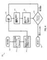
1つの実施形態に係る硬化機器又は硬化システムの操作方法が、図4の例示の実施形態において描かれており、そして一般に200として指定されている。方法200は、標的表面からの反射光などの1つ以上のパラメータ又は特性、及び硬化機器100自体の1つ以上の検知特性に基づくフィードバックを使用して、コントローラ10において制御モジュールとして実行され得る。例示の実施形態において、方法200は、硬化操作を開始すること、及び、標的表面にデリバリーされる光エネルギーの量を追跡するアキュムレータ又は積分回路を再設定することを含むことができる。工程210及び212。コントローラ10は、その後、予め選択された光源出力レベルなどの初期の設定に従って光源24を出力するように光学ドライブ回路22に指示し、それにより標的表面への光の適用を開始することができる。工程214。リアルタイムの「デリバリーされた」エネルギー値は、露光時間の間にデジタル的に積分され、所与の時点までに標的表面にデリバリーされたエネルギーの合計ジュールを計算して表示することができる。工程216、218。デリバリーされたエネルギーが所望のレベルに達すると(例えば、濃い色調では48ジュール)、コントローラ10は、光源24を自動でオフにし、そして露光が完了したことを使用者に知らせることができる。工程220、222、224。このようにして、硬化機器100は、各々の使用の際に存在する距離又は角度変動など、標的表面への光エネルギーのデリバリーに影響を及ぼす要因を補償するために露光時間を変更することができる。 A method of operating a curing apparatus or system according to one embodiment is depicted in the exemplary embodiment of FIG.
1つの実施形態に係る硬化機器の操作の別の方法は、図5の例示の実施形態において描かれており、一般に300で指定されている。方法300は、方法200と同様のコントローラ10により実施され得る。例示の実施形態において、方法300は、硬化操作を開始すること、及び、標的表面にデリバリーされる光エネルギーの量を追跡するアキュムレータ又は積分回路を開始又は再設定することを含むことができる。工程310及び312。硬化操作の開始は、オペレータインプット12のユーザインプット(例えば、ボタン)の作動に応答して開始することができる。コントローラ10は、その後、事前選択された光源出力レベルなどの初期設定に従って光源24を出力するように光学ドライブ回路22に指示し、それにより標的表面への光の適用を開始することができる。工程314。方法300は、オペレータにより初期設定又は期待された目標照射レベルに関して、その瞬間での標的表面における過露光又は露光不足を表すリアルタイムでの誤差値を生成するために標的表面での照射量を計算することをさらに含むことができる。工程318、320。 Another method of operation of curing equipment according to one embodiment is depicted in the exemplary embodiment of FIG. 5 and generally designated 300 .
この誤差シグナルは、その後、光学ドライブ回路22を調節するための基準として使用され、計算値により光源24からのアウトプットを増加し又は低減することができ、そしてそれにより、光源24と標的表面との間のエネルギー損失が補償され、そして標的表面が、硬化プロセスの任意の所与の瞬間での照射の目標数値mW/cm2を受けることを確実にすることができる。工程322、324、326。例として、工程322で、方法300は、デリバリーされた照射量(Idelivered)が、期待される照射量の計算量より大きいか又は小さいかを決定することができ、その計算量は、所与の時間での所望又は期待される照射量(Idesired)に対応することができる。別の例として、方法300は、デリバリーされたエネルギーの量(Jdelivered)が、期待されるエネルギーの計算量よりも高いか又は低いかを決定することができ、その計算量は、所与の時間での所望又は期待されるエネルギーの量(Jdesired)に対応することができ、又は、硬化操作が開始されてからの期間の硬化操作のための合計の所定エネルギー量の一部分に対応することができる。方法300は、合計露光時間を短縮する代わりに過度の強力な照射レベルの実質的な回避を容易にすることができる。This error signal can then be used as a reference to adjust the
例示の実施形態の方法300は、予め決められた時間の後、例えば、0.01秒後に、光学センサーフィードバックシグナルに基づいて、標的表面にデリバリーされたエネルギーの合計量が硬化操作のための光エネルギーの所定量に対応するしきい値を満たすか又は超えるかどうかを決定することができる。工程328、330、332。合計エネルギーの計算量がこの条件を満たす場合、硬化操作を停止することができる。工程332、334。条件が満たされない場合、合計エネルギーの計算量が条件を満たすまで、エネルギーの計算量が反復して決定されるように硬化操作を継続することができる。工程332、316。 The
1つの実施形態に係る硬化機器100は、計算された露光時間を単に二倍又は三倍する従来のはるかに精度の低いアプローチに頼ることなく、複合歯科用材料などの硬化性材料を適切に硬化させるために十分なエネルギーを硬化性材料に受けさせることを実質的に確実にする構成を提供することができる。このようにして、標的表面への実質的に有効なエネルギー送達が達成され得る。本明細書中に記載される技術及び実施形態は、接着剤又は同様の複合材フィラーの精密な光硬化を利用する工業的製造などの非歯科用途に拡張され得ることは理解されるべきである。
場合により、硬化機器100は、例えば、硬化操作が、光学センサーフィードバックシグナルに基づいて、硬化性材料を適切に硬化するために不十分であるように見える場合など、不適切な位置合わせ、又は、エネルギーをデリバリーするのに不十分な能力に関連する問題を、その操作を防止するか又はそれをオペレータに警告するかのいずれか少なくとも1つを行うように構成され得る。例として、硬化機器100が、不適切に訓練されたオペレータがおそらく一部原因となって、不適切に角度付けられている場合、コントローラ10は、硬化操作が標的材料を硬化するのに不十分であることを検知することができ、そしてそれに応じてオペレータに警告するか、又は、操作を中止するか、あるいはその両方を行うことができる。 In some cases, the
1つの実施形態に係る硬化機器又は硬化システムの方法が図6の例示の実施形態において描かれ、そして、一般に400で指定される。例示の実施形態において、方法400は、方法200、300などの本明細書中に記載される方法の1つ以上に従った硬化操作を行う前に行われることができる。この方法400は、オペレータインプット12(例えば、ボタン)のユーザインプットの作動に応答して、標的表面にデリバリーされた検知エネルギーのアキュムレータ又は積分回路を再設定し又は開始することを含むことができる。工程410及び412。コントローラ10は、その後、予め選択された光源出力レベルなどの初期設定に従って光源24を出力するように光学ドライブ回路22に指示し、それにより、光の適用を開始することができる。工程414。コントローラ10は、光学フィードバック回路26により提供された光学センサーフィードバックシグナルを分析し、検知された反射光が、硬化性材料が光適用部材20により実際に標的とされていることを示すものであるかどうかを決定することができる。工程416、418。例として、コントローラ10は、検知された光を、標的とされた硬化性材料のタイプに関連するしきい値、パラメータ又はパラメータ範囲と比較して、硬化性材料が光源24から実際に光を受けているかどうかを決定することができる。検知された光がしきい値よりも低いか、又は、パラメータ範囲から逸脱している場合、コントローラ10は、硬化操作が有効でない可能性があるように、光適用部材20に対して不適切に配置されていることを決定することができる。この決定に基づいて、コントローラ10は、光源24の操作を停止するか、又は、オペレータフィードバック回路14により問題をオペレータに警告するか、又は、それらの組み合わせを行うことができる。工程420、422。検知された光が、硬化性材料を適切に標的としていることを示す、しきい値より高いことなどの1つ以上の基準を満たす場合、コントローラ10は、硬化操作におけるさらなる工程に進むことができ、該工程としては、方法200、300との関連で本明細書中に記載される1つ以上の工程が挙げられる。方法400は、既知又は所望のタイプの標的の表面以外の表面に光エネルギーを適用するのを実質的に回避するために、数マイクロ秒の間で行うことができる。 A method of curing equipment or system according to one embodiment is depicted in the exemplary embodiment of FIG. In an exemplary embodiment,
本明細書中に記載の1つ以上の実施形態に加えて又はその代わりとして、硬化光100は、空気又は別のガスを標的表面に向けて又は標的表面から遠ざかる方向に導くための空気パスを含むことができ、それにより、標的表面又は周囲の領域、あるいはその両方を冷却することができる。例として、図2において破線として示されるように、硬化光100は、クーラントシステム150を含むことができ、該システムは、例えば、加圧空気又は真空源と、標的表面から又は標的表面に対して空気を通すための空気パスを含む。このようにして、空気又は別のガスは、圧力又は真空によりそれぞれ押されるか又は引かれて、硬化される標的表面を通過し、増加された空気流により、標的表面で加速された表面冷却を誘導することができる。クーラントシステム150はまた、ガス流以外の他の冷却機構を利用することもでき、該機構としては、例えば、水蒸気又は水ミストを標的表面に向けることが挙げられる。 Additionally or alternatively to one or more embodiments described herein, the curing
1つの実施形態において、クーラントシステム150は、硬化機器100のベースに又はその付近に配置されることができるカップラーを含むことができ、カップラーは、加圧ガス又は真空の供給源に迅速かつ信頼性をもって接続することを可能にする。クーラントシステムは、加圧もしくは真空誘導されたガス流を指向させて収容し、そして硬化機器100の光適用部材20に向けて又はそこからガス流をガイドするために硬化機器のボディー内に配置された空気チャンネルを含むことができる。光適用部材20は、光適用部材20の先端に配置されて、そして照明ビーム64の方向に向けられて、硬化される標的表面に向けて(加圧ガス)又はそこから遠ざかる方向に向けて(真空)ガス流を指向させる指向ノズルを含むことができる。標的表面に実際にデリバリーされる合計エネルギーを管理するための、光学センサーフィードバックシグナルに基づく光源24からのアウトプットの閉ループ制御は、デバイスからデリバリーされる光エネルギーの合計量が、実際にデリバリーされる光の量におけるオペレータによって誘発される変動を補償するために、必要とされる量よりも2倍又は3倍大きいように事前選択される従来の硬化操作と比較して、標的表面にデリバリーされる熱エネルギーの量を減じることができる。結果として、クーラントシステム150の使用が実質的に回避され得る。しかしながら、場合により、クーラントシステム150を硬化機器100中に組み込んで、より高いレベルの光強度でも作動する機会を提供し、それにより、標的表面で結果として生じる温度上昇を、決定されたしきい値を超えるレベルに実質的に上昇させることなしに、より急速な硬化を達成することができる。 In one embodiment, the
1つの実施形態において、硬化機器100の製造方法は、光学フィードバックセンサー28の光学パス62を光源24の光学パス64と位置合わせすることにより光適用部材20を組み立てることを含むことができる。該方法は、光が光インプット58から放出されるように光学フィードバックセンサー28にエネルギー供給することを含むことができる。光インプット58は、a)光源24に取り付けられたレンズ50の近傍で、及び、b)レンズ50と別のレンズ52との間に定義されたボイド又は領域内で配置され得る。光源24は、光が光インプット58から放出されるのと同時に、光を放出するためにエネルギー供給されることができる。光学フィードバックセンサー28は、光インプット58に対応するサイドファイヤー終端が光源24の光学パス64内で光学パス62に沿って光を指向するように回転及び移動され得る。光学パス64内の光学パス62の間の位置合わせが達成されると、光学フィードバックセンサー28は、光インプット58がレンズ50に対して実質的に安定した状態を維持するように適所に取り付けられ得る。1つの実施形態において、較正センサーシステムが、光インプット58の光学パス62及び光源24の光学パス64の相対位置を検知することができ、それにより、その位置合わせを容易にすることができる。較正又は位置合わせの間に光インプット58から放出される光は、光源24から放出される光とは異なるタイプであることができ、それにより、光学パス62と光学パス64との間の識別を容易にすることができる。 In one embodiment, a method of manufacturing curing
「垂直」、「水平」、「上(トップ)」、「下(ボトム)」、「上部(upper)」、「下部(lower)」、「内側(inner)」、「内側方向に(inwardly)」、「外側(outer)」、「外側方向に(outwardly)」などの方向用語は、図面に示した実施形態の向きに基づいて本開示を記載するのを補助するために使用される。方向用語の使用は、任意の特定の向きに本開示を限定するように解釈されるべきでない。 "vertical", "horizontal", "top", "bottom", "upper", "lower", "inner", "inwardly" , "outer," "outwardly," etc. are used to help describe the present disclosure based on the orientation of the embodiments shown in the drawings. The use of directional terms should not be construed to limit the disclosure to any particular orientation.
上記の記載は、本発明の現在の実施形態の記載である。様々な改変及び変更は、添付の特許請求の範囲において規定されるとおりの本発明の主旨及びより広い態様から逸脱することなくなされることができ、それは均等論を含む特許法の原則に従って解釈されるべきである。本開示は、例示の目的で示され、そして本発明のすべての実施形態の網羅的な記載と解釈されるべきでなく、又は、これらの実施形態に関連して例示され又は記載された特定の要素に特許請求の範囲を限定するように解釈されるべきでない。例えば、限定することなく、記載された発明の任意の個々の要素は、実質的に同様の機能を提供するか、又は、別のやりかたで適切な操作を提供する代替の要素により置き換えられてよい。これには、例えば、現在知られている代替要素、例えば、当業者に現在知られている可能性のあるもの、及び、将来開発され得る代替要素、例えば、当業者が開発時に代替物として認識するものが含まれる。さらに、開示の実施形態は、協調して記載されており、及び、協働的に利益の集合体を提供する複数の特徴を含む。本発明は、発行された特許請求の範囲に別途明示的に記載されている範囲を除き、これらの特徴のすべてを含み又は記載された利益のすべてを提供する実施形態のみに限定されない。例えば、冠詞「一つの(a)」、「一つの(an)」、「その(the)」又は「前記(said)」を用いた単数形の特許請求の範囲の要素のすべての言及は、その要素を単数に限定するものと解釈されるべきでない。 The above description is that of the current embodiment of the invention. Various modifications and changes can be made without departing from the spirit and broader aspects of the invention as defined in the appended claims, which are construed in accordance with the principles of patent law, including the doctrine of equivalents. should. This disclosure is presented for purposes of illustration and is not to be construed as an exhaustive description of all embodiments of the invention, or of the specific examples illustrated or described in connection with these embodiments. The elements should not be construed to limit the scope of the claims. For example, without limitation, any individual element of the described invention may be replaced by an alternative element that provides substantially similar functionality or that otherwise provides suitable operation. . This includes, for example, alternatives that are presently known, e.g., that may be presently known to those skilled in the art, and alternatives that may be developed in the future, e.g. includes those that Moreover, the disclosed embodiments have been described in concert and include multiple features that cooperatively provide a collective benefit. The invention is not limited to only embodiments that include all of these features or provide all of the stated benefits, except to the extent that such claims are expressly recited otherwise in the issued claims. For example, all references to claim elements in the singular using the articles "a," "an," "the," or "said" It should not be construed as limiting the elements to the singular.
上記の記載は、本発明の現在の実施形態の記載である。様々な改変及び変更は、添付の特許請求の範囲において規定されるとおりの本発明の主旨及びより広い態様から逸脱することなくなされることができ、それは均等論を含む特許法の原則に従って解釈されるべきである。本開示は、例示の目的で示され、そして本発明のすべての実施形態の網羅的な記載と解釈されるべきでなく、又は、これらの実施形態に関連して例示され又は記載された特定の要素に特許請求の範囲を限定するように解釈されるべきでない。例えば、限定することなく、記載された発明の任意の個々の要素は、実質的に同様の機能を提供するか、又は、別のやりかたで適切な操作を提供する代替の要素により置き換えられてよい。これには、例えば、現在知られている代替要素、例えば、当業者に現在知られている可能性のあるもの、及び、将来開発され得る代替要素、例えば、当業者が開発時に代替物として認識するものが含まれる。さらに、開示の実施形態は、協調して記載されており、及び、協働的に利益の集合体を提供する複数の特徴を含む。本発明は、発行された特許請求の範囲に別途明示的に記載されている範囲を除き、これらの特徴のすべてを含み又は記載された利益のすべてを提供する実施形態のみに限定されない。例えば、冠詞「一つの(a)」、「一つの(an)」、「その(the)」又は「前記(said)」を用いた単数形の特許請求の範囲の要素のすべての言及は、その要素を単数に限定するものと解釈されるべきでない。
以上、本発明を要約すると下記のとおりである。
1.標的を硬化するための歯科硬化機器であって、該標的は光エネルギーの適用に応答して硬化することができる修復材料を含み、該歯科硬化機器は、
修復材料を硬化するために光エネルギーをアウトプットすることができる光源、
光エネルギー特性を検知するための光センサー、
光センサーに操作可能にカップリングされた光学フィードバックパス、および
光センサー及び光源に操作可能にカップリングされたコントローラ
を含み、ここで、
該光源はアウトプットされる光エネルギーを変化させるように制御可能であり、
該光学フィードバックパスは標的から反射して戻される光を光センサーに送るように配置されており、ここで、該光センサーは標的から反射して戻される光に関する光エネルギー特性を検知するように構成されており、
該コントローラは、光センサーにより検知された光エネルギー特性に基づいて、光源の操作特性を変化させ、光源からアウトプットされる光エネルギーに影響を及ぼすように構成されている、
歯科硬化機器。
2.前記光学フィードバックパスは、光学フィードバックパスが照射ビームの範囲内になるように、歯科硬化機器からアウトプットされる光源の光の照射ビームと位置合わせされている、上記1記載の歯科硬化機器。
3.前記光学フィードバックパスは、前記照射ビームと同軸的に位置合わせされている、上記2記載の歯科硬化機器。
4.前記光センサーは、前記照射ビームをシャドー化することを実質的に回避するように配置されている、上記3記載の歯科硬化機器。
5.前記光学フィードバックパス及び前記光センサーは、前記コントローラへの分離された光学フィードバックを形成し、ここで、コントローラは標的の表面にデリバリーされる実際の光強度(mW/cm2)をリアルタイムで評価するように構成されており、該評価は標的に対する歯科硬化機器の提示の距離又は角度のうちの少なくとも1つにより引き起こされるオペレータが誘発する変動から独立している、上記1記載の歯科硬化機器。
6.前記光センサーはリアルタイム強度光学センサーフィードバックシグナルを提供し、前記コントローラは、該光学センサーフィードバックシグナルに基づいて、前記光源の光源強度を制御することにより補正調節を生じさせ、それによってコントローラは標的の表面にデリバリーされる実際の光強度を安定化させる、上記1記載の歯科硬化機器。
7.前記コントローラは前記標的上の光強度の時間積分を決定するための基準として、前記光学センサーフィードバックシグナルをさらに使用するようにプログラムされており、該コントローラは該標的の表面にデリバリーされる実際の合計エネルギーをリアルタイムで計算するようにプログラムされている、上記6記載の歯科硬化機器。
8.前記実際の合計エネルギーはw/cm2 * tsec.での強度に等しいジュール/cm2でのエネルギーで表現される、上記7記載の歯科硬化機器。
9.前記コントローラは、活性露光(active exposure)の時間をさらに管理することによりデリバリーされるエネルギー量を制御するために、光源を制御するための基準としてジュール/cm2のリアルタイム計算を使用する、上記7記載の歯科硬化機器。
10.前記光学フィードバックパスは光デリバリーパスと共有されており、光デリバリーパスを介して前記光源が前記標的にエネルギーをアウトプットし、
ここで、前記コントローラは、光源からアウトプットされる光エネルギーと標的から反射して戻される光を、差異として(differentially)及び比率として(ratiometrically)評価するようにプログラムされており、ここで、アウトプットされる光エネルギーと反射して戻される光の指標であるシグナルは、該共有された光デリバリーパス内から得られる、上記1記載の歯科硬化機器。
11.前記光エネルギー特性に基づく組み込み診断(BID)をさらに含む、上記1記載の歯科硬化機器。
12.前記BIDは、光源の問題、バッテリーの問題及び先端汚染のうちの少なくとも1つを検知する能力を含む、上記1記載の歯科硬化機器。
13.前記コントローラは、硬化操作がボタンにより作動される場合に前記光源からアウトプットされる光エネルギーのパスに前記標的が存在しているか否かを確認し、そして標的が存在していないとの決定に応答して、光源を停止するように構成されている、上記1記載の歯科硬化機器。
14.前記コントローラはマイクロ秒のオーダーでの時間枠で存在を決定しそして前記光源を停止するようにプログラムされている、上記1記載の歯科硬化機器。
15.前記標的は歯又は不透明対象物である、上記1記載の歯科硬化機器。
16.光硬化性材料の硬化操作を行うための硬化機器の操作方法であって、該方法は、
光源から光エネルギーを発生させること、
該光エネルギーを光硬化性材料が結合された標的表面に向けること、
該標的表面から反射された検知光に基づいて光学センサーフィードバックシグナルを発生させること、及び、
該光学センサーフィードバックシグナルに基づいて、該光源からの光エネルギーのアウトプットを調節すること、
を含む、方法。
17.前記標的表面から反射された光を、光学センサーを介して検知することをさらに含み、ここで、該表面から反射された光は前記光源から該標的表面に実際にデリバリーされた光エネルギーの量を示す、上記16記載の方法。
18.光エネルギーを発生させるために前記光源に出力シグナルを供給することをさらに含み、ここで、光源からの光エネルギーのアウトプットの前記調節が、光源に供給される出力シグナルの特性を変化させることを含む、上記16記載の方法。
19.前記出力シグナルの特性は、電流の大きさ、電圧の大きさ、出力供給シグナルのデューティサイクルの少なくとも1つを含む、上記18記載の方法。
20.前記硬化機器は光エネルギーを放出する光適用部材を含み、そして前記方法は、前記光学センサーフィードバックシグナルに基づいて、前記光硬化性材料が光適用部材の近傍に存在するかどうかを決定することをさらに含む、上記16記載の方法。
21.前記光学センサーフィードバックシグナルに基づいて、前記標的表面にデリバリーされた光エネルギーの合計量を反復的に計算すること、及び、光エネルギーの計算量が前記光硬化性材料のための所定の光エネルギーの量と等しいかまたはそれを上回るかどうかを決定することをさらに含む、上記16記載の方法。
22.硬化プロファイルに従って前記標的表面に光エネルギーをデリバリーすること、
前記光学センサーフィードバックシグナルに基づいて、ある時間の間にデリバリーされた光エネルギーの量を計算すること、
該光エネルギーの計算量が、該ある時間での硬化プロファイルに従った光エネルギーの期待量に実質的に等しいかどうかを決定すること、
該光エネルギーの計算量が該光エネルギーの期待量と異なるとの決定に基づいて、前記光源からの光エネルギーのアウトプットを調節すること、
をさらに含む、上記16記載の方法。
23.前記硬化機器のガスチャンネルを通して正圧又は負圧を発生させることにより、前記標的表面上にガスを指向させることをさらに含む、上記16記載の方法。
24.光硬化性材料を硬化するための硬化機器であって、該硬化機器は、
光硬化性材料を硬化するために光エネルギーを発生させるように構成された光源、
光源に操作可能にカップリングされた光学ドライブ回路、
光学ドライブ回路に操作可能にカップリングされたコントローラ、
光硬化性材料から反射された光を回収するように配置され、光硬化性材料に向けられた光学センスパスとともに光インプットを有する、光学フィードバックセンサー、および
光学フィードバックセンサーの光インプットに光学的にカップリングされた光センサー
を含み、ここで、
該光源は該光硬化性材料に光エネルギーの照射ビームを提供するように構成されており、
該光学ドライブ回路は、該光エネルギーを発生させるために該光源に出力シグナルを提供するように構成されており、ここで、該光学ドライブ回路は、該光源からの光エネルギーのアウトプットを変化させるために該出力シグナルの1つ以上の操作特性を変化させるように構成されており、
該コントローラは、該光源からの該光エネルギーの発生を制御するために該光学ドライブ回路の操作を制御するように構成されており、
該光インプットの該光学センスパスは、該光源から発生される該照明ビームにより包囲されており、
該光センサーは、該光インプットにより回収された光に基づいて、光学センサーフィードバックシグナルを発生するように構成され、ここで、該コントローラは、該光学センサーフィードバックシグナルに基づいて、該光源からの光エネルギーのアウトプットを変化させるために、該1つ以上の操作特性の少なくとも1つを変化させるように該光学ドライブ回路に指令する、硬化機器。
25.前記光学センスパスは光エネルギーの前記照明ビームと同軸的に位置合わせされており、前記光センサーは該照明ビームの有意なシャドー化を実質的に回避するように前記光源に対して配置されている、上記24記載の硬化機器。
26.前記光硬化性材料の温度に影響を及ぼすように光硬化性材料上にガスを指向させるガスノズルにカップリングされたガスチャンネルをさらに含み、ここで、該ガスチャンネルはクーラントシステムの少なくとも一部を形成している、上記24記載の硬化機器。The above description is that of the current embodiment of the invention. Various modifications and changes can be made without departing from the spirit and broader aspects of the invention as defined in the appended claims, which are construed in accordance with the principles of patent law, including the doctrine of equivalents. should. This disclosure is presented for purposes of illustration and is not to be construed as an exhaustive description of all embodiments of the invention, or of the specific examples illustrated or described in connection with these embodiments. The elements should not be construed to limit the scope of the claims. For example, without limitation, any individual element of the described invention may be replaced by an alternative element that provides substantially similar functionality or that otherwise provides suitable operation. . This includes, for example, alternatives that are presently known, e.g., that may be presently known to those skilled in the art, and alternatives that may be developed in the future, e.g. includes those that Moreover, the disclosed embodiments have been described in concert and include multiple features that cooperatively provide a collective benefit. The invention is not limited to only embodiments that include all of these features or provide all of the stated benefits, except to the extent that such claims are expressly recited otherwise in the issued claims. For example, all references to claim elements in the singular using the articles "a,""an,""the," or "said" It should not be construed as limiting the elements to the singular.
As described above, the present invention is summarized as follows.
1. A dental curing device for curing a target, the target comprising a restorative material capable of curing in response to application of light energy, the dental curing device comprising:
a light source capable of outputting light energy to cure the restorative material;
a light sensor for sensing light energy characteristics;
an optical feedback path operably coupled to the light sensor; and a controller operably coupled to the light sensor and the light source, wherein:
the light source is controllable to vary the output light energy;
The optical feedback path is arranged to send light reflected back from the target to an optical sensor, where the optical sensor is configured to sense a light energy characteristic of the light reflected back from the target. has been
The controller is configured to change the operational characteristics of the light source to affect the light energy output from the light source based on the light energy characteristics sensed by the light sensor.
Dental curing equipment.
2. 2. The dental curing instrument of claim 1, wherein the optical feedback path is aligned with the illumination beam of light of the light source output from the dental curing instrument such that the optical feedback path is within the illumination beam.
3. 3. The dental curing instrument of claim 2, wherein the optical feedback path is coaxially aligned with the illumination beam.
4. 4. Dental curing appliance according to claim 3, wherein the optical sensor is arranged to substantially avoid shadowing the radiation beam.
5. The optical feedback path and the light sensor form a separate optical feedback to the controller, where the controller evaluates in real time the actual light intensity (mW/cm2) delivered to the target surface. 2. The dental curing instrument of claim 1, wherein said evaluation is independent of operator-induced variations caused by at least one of the distance or angle of presentation of the dental curing instrument relative to the target.
6. The optical sensor provides a real-time intensity optical sensor feedback signal, and the controller produces corrective adjustments by controlling the light source intensity of the light source based on the optical sensor feedback signal, whereby the controller controls the surface of the target. 2. A dental curing device according to claim 1, which stabilizes the actual light intensity delivered to the.
7. The controller is further programmed to use the optical sensor feedback signal as a basis for determining the time integral of light intensity on the target, the controller determining the actual total delivered to the surface of the target. 7. A dental curing appliance according to claim 6, programmed to calculate energy in real time.
8. Said actual total energy is w/cm2*tsec. 8. A dental hardening appliance according to Claim 7, expressed in energy in Joules/cm2 equal to the intensity at .
9. 7, wherein the controller uses real-time calculation of Joules/cm2 as a basis for controlling the light source to control the amount of energy delivered by further managing the time of active exposure. of dental curing equipment.
10. the optical feedback path is shared with an optical delivery path through which the light source outputs energy to the target;
wherein said controller is programmed to differentially and ratiometrically evaluate light energy output from a light source and light reflected back from a target, wherein: 2. The dental curing appliance of claim 1, wherein a signal indicative of light energy received and light reflected back is obtained from within said shared light delivery path.
11. 2. The dental curing appliance of claim 1, further comprising built-in diagnostics (BID) based on said light energy characteristics.
12. 2. The dental curing appliance of claim 1, wherein the BID includes the ability to detect at least one of light source problems, battery problems and tip contamination.
13. The controller checks whether the target is present in the path of light energy output from the light source when a curing operation is activated by a button, and determines that the target is not present. 2. A dental curing appliance according to claim 1, configured to turn off the light source in response.
14. 2. A dental curing appliance according to claim 1, wherein said controller is programmed to determine presence and turn off said light source in a time frame on the order of microseconds.
15. 2. A dental hardening appliance according to claim 1, wherein the target is a tooth or an opaque object.
16. 1. A method of operating a curing equipment for performing a curing operation of a photocurable material, the method comprising:
generating light energy from a light source;
directing the light energy to a target surface to which the photocurable material is bound;
generating an optical sensor feedback signal based on sensed light reflected from the target surface; and
adjusting light energy output from the light source based on the optical sensor feedback signal;
A method, including
17. further comprising sensing light reflected from the target surface via an optical sensor, wherein the light reflected from the surface measures the amount of light energy actually delivered to the target surface from the light source; 17. The method of claim 16, wherein
18. further comprising providing an output signal to said light source for generating light energy, wherein said adjusting the output of light energy from said light source changes a characteristic of the output signal provided to said light source. 17. The method of claim 16, comprising
19. 19. The method of claim 18, wherein the characteristics of the output signal include at least one of current magnitude, voltage magnitude, duty cycle of the output supply signal.
20. The curing device includes a light-applying member that emits light energy, and the method includes determining whether the light-curable material is in the vicinity of the light-applying member based on the optical sensor feedback signal. 17. The method of claim 16, further comprising.
21. iteratively calculating a total amount of light energy delivered to the target surface based on the optical sensor feedback signal; and wherein the calculated amount of light energy is a predetermined amount of light energy for the photocurable material. 17. The method of claim 16, further comprising determining whether the amount is equal to or greater than.
22. delivering light energy to the target surface according to a cure profile;
calculating the amount of light energy delivered over time based on the optical sensor feedback signal;
determining whether the calculated amount of light energy is substantially equal to the expected amount of light energy according to the curing profile over time;
adjusting the output of light energy from the light source based on determining that the calculated amount of light energy differs from the expected amount of light energy;
17. The method of claim 16, further comprising
23. 17. The method of claim 16, further comprising directing gas onto the target surface by generating a positive or negative pressure through gas channels of the curing equipment.
24. A curing device for curing a photocurable material, the curing device comprising:
a light source configured to generate light energy to cure the photocurable material;
an optical drive circuit operably coupled to the light source;
a controller operably coupled to the optical drive circuitry;
An optical feedback sensor arranged to collect light reflected from the photocurable material and having an optical input with an optical sense path directed to the photocurable material; and optically coupled to the optical input of the optical feedback sensor. a light sensor, where:
the light source is configured to provide an illuminating beam of light energy to the photocurable material;
The optical drive circuitry is configured to provide an output signal to the light source to generate the light energy, wherein the optical drive circuitry varies the output of light energy from the light source. configured to change one or more operational characteristics of the output signal for
the controller configured to control operation of the optical drive circuit to control the generation of the light energy from the light source;
the optical sense path of the light input is surrounded by the illumination beam generated from the light source;
The optical sensor is configured to generate an optical sensor feedback signal based on light collected by the light input, wherein the controller controls light from the light source based on the optical sensor feedback signal. A curing device that commands the optical drive circuit to change at least one of the one or more operating characteristics to change the output of energy.
25. wherein the optical sense path is coaxially aligned with the illumination beam of light energy and the photosensor is positioned relative to the light source to substantially avoid significant shadowing of the illumination beam; 25. Curing equipment according to 24 above.
26. further comprising a gas channel coupled to a gas nozzle for directing gas onto the photocurable material to affect the temperature of the photocurable material, wherein the gas channel forms at least part of a coolant system 25. The curing device of
Claims (26)
Translated fromJapanese修復材料を硬化するために光エネルギーをアウトプットすることができる光源、
光エネルギー特性を検知するための光センサー、
光センサーに操作可能にカップリングされた光学フィードバックパス、および
光センサー及び光源に操作可能にカップリングされたコントローラ
を含み、ここで、
該光源はアウトプットされる光エネルギーを変化させるように制御可能であり、
該光学フィードバックパスは標的から反射して戻される光を光センサーに送るように配置されており、ここで、該光センサーは標的から反射して戻される光に関する光エネルギー特性を検知するように構成されており、
該コントローラは、光センサーにより検知された光エネルギー特性に基づいて、光源の操作特性を変化させ、光源からアウトプットされる光エネルギーに影響を及ぼすように構成されている、
歯科硬化機器。A dental curing device for curing a target, the target comprising a restorative material capable of curing in response to application of light energy, the dental curing device comprising:
a light source capable of outputting light energy to cure the restorative material;
a light sensor for sensing light energy characteristics;
an optical feedback path operably coupled to the light sensor; and a controller operably coupled to the light sensor and the light source, wherein:
the light source is controllable to vary the output light energy;
The optical feedback path is arranged to send light reflected back from the target to an optical sensor, where the optical sensor is configured to sense a light energy characteristic of the light reflected back from the target. has been
The controller is configured to change the operational characteristics of the light source to affect the light energy output from the light source based on the light energy characteristics sensed by the light sensor.
Dental curing equipment.
ここで、前記コントローラは、光源からアウトプットされる光エネルギーと標的から反射して戻される光を、差異として(differentially)及び比率として(ratiometrically)評価するようにプログラムされており、ここで、アウトプットされる光エネルギーと反射して戻される光の指標であるシグナルは、該共有された光デリバリーパス内から得られる、請求項1記載の歯科硬化機器。the optical feedback path is shared with an optical delivery path through which the light source outputs energy to the target;
wherein said controller is programmed to differentially and ratiometrically evaluate light energy output from a light source and light reflected back from a target, wherein: 2. The dental curing appliance of claim 1, wherein a signal indicative of light energy emitted and light reflected back is obtained from within the shared light delivery path.
光源から光エネルギーを発生させること、
該光エネルギーを光硬化性材料が結合された標的表面に向けること、
該標的表面から反射された検知光に基づいて光学センサーフィードバックシグナルを発生させること、及び、
該光学センサーフィードバックシグナルに基づいて、該光源からの光エネルギーのアウトプットを調節すること、
を含む、方法。1. A method of operating a curing equipment for performing a curing operation of a photocurable material, the method comprising:
generating light energy from a light source;
directing the light energy to a target surface to which the photocurable material is bound;
generating an optical sensor feedback signal based on sensed light reflected from the target surface; and
adjusting light energy output from the light source based on the optical sensor feedback signal;
A method, including
前記光学センサーフィードバックシグナルに基づいて、ある時間の間にデリバリーされた光エネルギーの量を計算すること、
該光エネルギーの計算量が、該ある時間での硬化プロファイルに従った光エネルギーの期待量に実質的に等しいかどうかを決定すること、
該光エネルギーの計算量が該光エネルギーの期待量と異なるとの決定に基づいて、前記光源からの光エネルギーのアウトプットを調節すること、
をさらに含む、請求項16記載の方法。delivering light energy to the target surface according to a cure profile;
calculating the amount of light energy delivered over time based on the optical sensor feedback signal;
determining whether the calculated amount of light energy is substantially equal to the expected amount of light energy according to the curing profile over time;
adjusting the output of light energy from the light source based on determining that the calculated amount of light energy differs from the expected amount of light energy;
17. The method of claim 16, further comprising:
光硬化性材料を硬化するために光エネルギーを発生させるように構成された光源、
光源に操作可能にカップリングされた光学ドライブ回路、
光学ドライブ回路に操作可能にカップリングされたコントローラ、
光硬化性材料から反射された光を回収するように配置され、光硬化性材料に向けられた光学センスパスとともに光インプットを有する、光学フィードバックセンサー、および
光学フィードバックセンサーの光インプットに光学的にカップリングされた光センサー
を含み、ここで、
該光源は該光硬化性材料に光エネルギーの照射ビームを提供するように構成されており、
該光学ドライブ回路は、該光エネルギーを発生させるために該光源に出力シグナルを提供するように構成されており、ここで、該光学ドライブ回路は、該光源からの光エネルギーのアウトプットを変化させるために該出力シグナルの1つ以上の操作特性を変化させるように構成されており、
該コントローラは、該光源からの該光エネルギーの発生を制御するために該光学ドライブ回路の操作を制御するように構成されており、
該光インプットの該光学センスパスは、該光源から発生される該照明ビームにより包囲されており、
該光センサーは、該光インプットにより回収された光に基づいて、光学センサーフィードバックシグナルを発生するように構成され、ここで、該コントローラは、該光学センサーフィードバックシグナルに基づいて、該光源からの光エネルギーのアウトプットを変化させるために、該1つ以上の操作特性の少なくとも1つを変化させるように該光学ドライブ回路に指令する、硬化機器。A curing device for curing a photocurable material, the curing device comprising:
a light source configured to generate light energy to cure the photocurable material;
an optical drive circuit operably coupled to the light source;
a controller operably coupled to the optical drive circuitry;
An optical feedback sensor arranged to collect light reflected from the photocurable material and having an optical input with an optical sense path directed to the photocurable material; and optically coupled to the optical input of the optical feedback sensor. a light sensor, where:
the light source is configured to provide an illuminating beam of light energy to the photocurable material;
The optical drive circuitry is configured to provide an output signal to the light source to generate the light energy, wherein the optical drive circuitry varies the output of light energy from the light source. configured to change one or more operational characteristics of the output signal for
the controller configured to control operation of the optical drive circuit to control the generation of the light energy from the light source;
the optical sense path of the light input is surrounded by the illumination beam generated from the light source;
The optical sensor is configured to generate an optical sensor feedback signal based on light collected by the light input, wherein the controller controls light from the light source based on the optical sensor feedback signal. A curing device that commands the optical drive circuit to change at least one of the one or more operating characteristics to change the output of energy.
Applications Claiming Priority (3)
| Application Number | Priority Date | Filing Date | Title |
|---|---|---|---|
| US201462051472P | 2014-09-17 | 2014-09-17 | |
| US62/051,472 | 2014-09-17 | ||
| JP2021018063AJP7305687B2 (en) | 2014-09-17 | 2021-02-08 | dental curing light |
Related Parent Applications (1)
| Application Number | Title | Priority Date | Filing Date |
|---|---|---|---|
| JP2021018063ADivisionJP7305687B2 (en) | 2014-09-17 | 2021-02-08 | dental curing light |
Publications (1)
| Publication Number | Publication Date |
|---|---|
| JP2023060856Atrue JP2023060856A (en) | 2023-04-28 |
Family
ID=55453647
Family Applications (3)
| Application Number | Title | Priority Date | Filing Date |
|---|---|---|---|
| JP2017534901AWithdrawnJP2017533058A (en) | 2014-09-17 | 2015-09-17 | Dental curing light |
| JP2021018063AActiveJP7305687B2 (en) | 2014-09-17 | 2021-02-08 | dental curing light |
| JP2023018376APendingJP2023060856A (en) | 2014-09-17 | 2023-02-09 | dental curing light |
Family Applications Before (2)
| Application Number | Title | Priority Date | Filing Date |
|---|---|---|---|
| JP2017534901AWithdrawnJP2017533058A (en) | 2014-09-17 | 2015-09-17 | Dental curing light |
| JP2021018063AActiveJP7305687B2 (en) | 2014-09-17 | 2021-02-08 | dental curing light |
Country Status (8)
| Country | Link |
|---|---|
| US (3) | US10159548B2 (en) |
| EP (1) | EP3193776B1 (en) |
| JP (3) | JP2017533058A (en) |
| KR (1) | KR20170058977A (en) |
| CN (1) | CN107106270A (en) |
| BR (1) | BR112017005431A2 (en) |
| ES (1) | ES2905363T3 (en) |
| WO (1) | WO2016044549A1 (en) |
Families Citing this family (21)
| Publication number | Priority date | Publication date | Assignee | Title |
|---|---|---|---|---|
| US10231810B2 (en)* | 2012-09-14 | 2019-03-19 | 3M Innovative Properties Company | Dental irradiation device and system |
| EP2944288B1 (en)* | 2014-05-12 | 2020-04-08 | Ivoclar Vivadent AG | Light curing device, in particular dental light curing device |
| JP2017533058A (en) | 2014-09-17 | 2017-11-09 | ギャリソン デンタル ソリューションズ,リミティド ライアビリティ カンパニー | Dental curing light |
| US10479073B2 (en)* | 2015-03-27 | 2019-11-19 | Phoseon Technology, Inc. | Light engine frame with integrated baffle |
| US10758126B2 (en)* | 2015-04-10 | 2020-09-01 | 3M Innovative Properties Company | Dental irradiation device |
| EP3106124B1 (en)* | 2015-06-17 | 2019-09-04 | Ivoclar Vivadent AG | Light hardening device |
| US10568726B2 (en)* | 2015-08-06 | 2020-02-25 | Transparent Materials, Llc | Photocomposite, light source and thermal detector |
| USD828563S1 (en)* | 2015-08-14 | 2018-09-11 | Ivoclar Vivadent Ag | Control module for a dental light hardening device |
| EP3491049A4 (en) | 2016-07-29 | 2020-03-18 | 3M Innovative Properties Company | Cure monitoring systems and methods |
| US20190201176A1 (en)* | 2017-06-09 | 2019-07-04 | Garrison Dental Solutions, Llc | Curing light device assembly |
| WO2018227077A1 (en)* | 2017-06-09 | 2018-12-13 | Garrison Dental Solutions | Curing light device assembly |
| US11439839B2 (en)* | 2017-08-09 | 2022-09-13 | Acuity Innovation And Design, Llc | Hand-held treatment device using LED light sources with interchangeable emitters |
| US12274597B2 (en)* | 2017-08-11 | 2025-04-15 | Align Technology, Inc. | Dental attachment template tray systems |
| US20190183620A1 (en)* | 2017-12-14 | 2019-06-20 | Garrison Dental Solutions, Llc | Curing light with integrated feedback sensor |
| US11589971B2 (en) | 2018-11-14 | 2023-02-28 | Garrison Dental Solutions, L.L.C. | Dental curing light and method |
| US20230404730A1 (en)* | 2019-07-29 | 2023-12-21 | Cao Group, Inc. | Curing light and therapeutic laser systems and related methods |
| KR20220056179A (en)* | 2019-07-29 | 2022-05-04 | 카오 그룹, 인코포레이티드 | A system that combines a therapeutic laser and polymerization light |
| US20230346530A1 (en)* | 2022-01-30 | 2023-11-02 | Cao Group, Inc. | Curing light and theraputic laser systems and related methods |
| USD1022306S1 (en)* | 2020-05-01 | 2024-04-09 | Water Pik, Inc. | Light guide |
| KR102822855B1 (en)* | 2022-11-11 | 2025-06-18 | 장보경 | lamp for dental prosthetics |
| USD1095866S1 (en)* | 2023-08-03 | 2025-09-30 | Shenzhen Echelon Training Co., Ltd. | Adhesive curing pen |
Family Cites Families (332)
| Publication number | Priority date | Publication date | Assignee | Title |
|---|---|---|---|---|
| US3638312A (en) | 1969-12-29 | 1972-02-01 | Freeman Chemical Corp | Apparatus for concentrating ultraviolet radiation, for curing polymerizable compositions and method for hardening filling compositions in dental cavities |
| US4281645A (en) | 1977-06-28 | 1981-08-04 | Duke University, Inc. | Method and apparatus for monitoring metabolism in body organs |
| US4309617A (en) | 1979-03-05 | 1982-01-05 | Minnesota Mining And Manufacturing Company | Pulsed radiation source adapted for curing dental restoratives |
| US4385344A (en) | 1980-08-29 | 1983-05-24 | Dentsply Research & Development Corp. | Visible light apparatus for curing photo-curable compositions |
| US4445858A (en) | 1982-02-19 | 1984-05-01 | American Hospital Supply Corporation | Apparatus for photo-curing of dental restorative materials |
| US4716296A (en) | 1982-04-26 | 1987-12-29 | Surgicorp | Apparatus for curing dental restorative composites |
| US4450139A (en) | 1982-05-03 | 1984-05-22 | Solid State Systems, Corporation | Light generating apparatus for curing dental restorative composites |
| DE3516774A1 (en) | 1985-05-09 | 1986-11-13 | Wilhelm Sedlbauer GmbH Fabrik für Feinmechanik und Elektronik, 8000 München | PROCESSING DEVICE FOR LOCAL RADIATION WITH VISIBLE OR INVISIBLE LIGHT |
| DE3534342C1 (en) | 1985-09-26 | 1987-03-12 | Kaltenbach & Voigt | Light transmitting dental hand-tool - for curing polymer based fillings |
| US4888489A (en) | 1988-05-09 | 1989-12-19 | Minnesota Mining And Manufacturing Company | Hand-held device for curing a dental restorative material |
| US4952143A (en) | 1988-05-17 | 1990-08-28 | Becker William J | Dental bleaching instrument |
| US5316473A (en) | 1988-06-17 | 1994-05-31 | Dentsply Research & Development Corp. | Light curing apparatus and method |
| US5201655A (en) | 1988-12-21 | 1993-04-13 | Joshua Friedman | Optical light guide for controlling the irradiation of a dental restorative material |
| US4924070A (en) | 1989-08-10 | 1990-05-08 | Joshua Friedman | Apparatus for controlled irradiation |
| US4948215A (en) | 1989-08-10 | 1990-08-14 | Joshua Friedman | Dental light-curing lamp unit with interchangeable autofocus light guides |
| US5184044A (en) | 1990-08-13 | 1993-02-02 | Welch Allyn, Inc. | Dental curing lamp |
| US5147204A (en) | 1991-08-08 | 1992-09-15 | Minnesota Mining And Manufacturing Co. | Dental material curing apparatus |
| DE4211230C2 (en) | 1992-04-03 | 1997-06-26 | Ivoclar Ag | Rechargeable light curing device |
| DE4222821C2 (en) | 1992-07-08 | 1994-09-22 | Ivoclar Ag | Modified chlorhexidine adduct |
| EP0920840A3 (en) | 1992-07-31 | 2000-03-29 | Molten Corporation | Small-sized light irradiator for dental use |
| US5290169A (en) | 1992-11-02 | 1994-03-01 | Joshua Friedman | Optical light guide for dental light-curing lamps |
| US5616141A (en) | 1993-04-09 | 1997-04-01 | Ion Laser Technology | Laser system for use in dental procedures |
| GB9309397D0 (en) | 1993-05-07 | 1993-06-23 | Patel Bipin C M | Laser treatment |
| US5420768A (en) | 1993-09-13 | 1995-05-30 | Kennedy; John | Portable led photocuring device |
| US5415543A (en) | 1993-12-20 | 1995-05-16 | Rozmajzl, Jr.; William F. | Dental composite curing apparatus and method |
| US5397892A (en) | 1994-01-07 | 1995-03-14 | Coltene/Whaledent, Inc. | Fiber optic light source for a dental curing lamp with two pegs for removably aligning the source with an intensity detector |
| US5487662A (en) | 1994-03-22 | 1996-01-30 | Minnesota Mining And Manufacturing Company | Dental impression tray for photocurable impression material |
| US5521392A (en) | 1994-04-29 | 1996-05-28 | Efos Canada Inc. | Light cure system with closed loop control and work piece recording |
| DE59506287D1 (en) | 1995-08-23 | 1999-07-29 | Wolfgang Stegemann | DENTAL INSTRUMENT |
| US6046460A (en) | 1995-11-17 | 2000-04-04 | Ivoclar Ag | Light curing device |
| US5880826A (en) | 1997-07-01 | 1999-03-09 | L J Laboratories, L.L.C. | Apparatus and method for measuring optical characteristics of teeth |
| US6254385B1 (en)* | 1997-01-02 | 2001-07-03 | Lj Laboratories, Llc | Apparatus and method for measuring optical characteristics of teeth |
| US5759030A (en)* | 1996-01-02 | 1998-06-02 | Lj Laboratories, L.L.C. | Method for determing optical characteristics of teeth |
| DE19613566C2 (en) | 1996-04-04 | 1998-03-12 | Peter Rechmann | Device and method for curing a light-curing plastic filling material |
| DE19618543C2 (en) | 1996-05-08 | 1998-07-02 | Ivoclar Ag | Polymerizer |
| US5803729A (en) | 1996-07-17 | 1998-09-08 | Efraim Tsimerman | Curing light |
| US5759032A (en) | 1996-07-24 | 1998-06-02 | Bartel; William B. | Device for applying pressure to photocurable materials during polymerization |
| US5942559A (en) | 1996-08-26 | 1999-08-24 | Ivoclar Ag | Dental light-curing opaquer |
| DE19636266A1 (en) | 1996-09-06 | 1998-03-12 | Kaltenbach & Voigt | Method and device for curing photosensitive polymeric compositions |
| JPH1097166A (en)* | 1996-09-20 | 1998-04-14 | Fuji Xerox Co Ltd | Cleaning device |
| CA2216053C (en) | 1996-09-20 | 2007-06-26 | Kuraray Co., Ltd. | Method of polymerizing photo-polymerizable composition for dental use and dental light-curing apparatus for use therewith |
| US5879159A (en) | 1996-12-24 | 1999-03-09 | Ion Laser Technology, Inc. | Portable high power arc lamp system and applications therefor |
| US6242505B1 (en) | 1997-03-07 | 2001-06-05 | Ivoclar Ag | Use of a photopolymerizable composition for the decoration of metallic ornaments |
| US6535878B1 (en) | 1997-05-02 | 2003-03-18 | Roxio, Inc. | Method and system for providing on-line interactivity over a server-client network |
| US5749724A (en) | 1997-05-12 | 1998-05-12 | Cheng; Sterling | Dental light curing device |
| DE29709228U1 (en) | 1997-05-26 | 1998-09-24 | THERA Patent GmbH & Co. KG Gesellschaft für industrielle Schutzrechte, 82229 Seefeld | Light curing unit |
| US6099520A (en) | 1997-06-10 | 2000-08-08 | Shimoji; Yutaka | Method of using a cordless medical laser to cure composites and sterilize living tissue |
| US6325791B1 (en) | 1997-06-10 | 2001-12-04 | Yutaka Shimoji | Method of using a cordless medical laser to cure composites |
| US6103203A (en) | 1997-08-15 | 2000-08-15 | Ultradent Products, Inc. | System and method for controlling a light actuator to achieve partial polymerization |
| US6089740A (en) | 1997-08-28 | 2000-07-18 | Kreativ, Inc. | Multipurpose dental lamp apparatus |
| AU1198199A (en) | 1997-10-29 | 1999-05-17 | Bisco, Inc. | Dental composite light curing system |
| US5975895A (en) | 1997-11-12 | 1999-11-02 | Coltene/Whaledent | Strobe light curing apparatus and method |
| US6200134B1 (en) | 1998-01-20 | 2001-03-13 | Kerr Corporation | Apparatus and method for curing materials with radiation |
| US6068474A (en) | 1998-01-30 | 2000-05-30 | Ivoclar Ag | Light curing device |
| US6322358B1 (en) | 1998-03-09 | 2001-11-27 | Ivoclar Ag | Curing device for light-induced curing of dental materials |
| US6095812A (en) | 1998-03-11 | 2000-08-01 | Ivoclar Ag | Device for curing with light |
| US6123545A (en) | 1998-04-08 | 2000-09-26 | Ivoclar A.G. | Mains-operated device for curing by light a polymerizable dental material |
| CN1194433C (en) | 1998-07-06 | 2005-03-23 | Tdk株式会社 | Electrodes for non-aqueous electrolyte batteries |
| US6208788B1 (en) | 1998-07-29 | 2001-03-27 | Ultradent Products, Inc. | Apparatus and methods for concentrating light through fiber optic funnels coupled to dental light guides |
| US6514075B1 (en) | 1998-09-15 | 2003-02-04 | Gregory S. Jacob | Dental curing apparatus for light-sensitive materials |
| US6254389B1 (en) | 1999-09-20 | 2001-07-03 | Marc Seghatol | Hand-held microwave intra-oral dental system |
| EP1031326A1 (en) | 1999-02-05 | 2000-08-30 | Jean-Michel Decaudin | Device for photo-activation of photosensitive composite materials especially in dentistry |
| US6482004B1 (en) | 1999-03-26 | 2002-11-19 | Ivoclar Ag | Light curing device and method for curing light-polymerizable dental material |
| US6102696A (en) | 1999-04-30 | 2000-08-15 | Osterwalder; J. Martin | Apparatus for curing resin in dentistry |
| US6439888B1 (en) | 1999-05-03 | 2002-08-27 | Pls Liquidating Llc | Optical source and method |
| US20030015667A1 (en)* | 1999-05-12 | 2003-01-23 | Macdougald Joseph A. | Curing unit |
| DE19928805C2 (en) | 1999-06-23 | 2003-03-27 | Ivoclar Vivadent Ag | Dental device with a display unit |
| US6193510B1 (en) | 1999-07-28 | 2001-02-27 | Efraim Tsimerman | Medical device with time-out feature |
| DE19943393C1 (en) | 1999-09-10 | 2001-01-25 | Espe Dental Ag | Dental material radiation device e.g. for hardening dental filling, has light beams from light-emitting diodes directed onto focus region at input end of light conductor |
| US6456895B1 (en) | 1999-09-13 | 2002-09-24 | Fitel Usa Corp. | Method and apparatus for detecting conditions in a UV curing lamp system |
| US6523019B1 (en) | 1999-09-21 | 2003-02-18 | Choicemaker Technologies, Inc. | Probabilistic record linkage model derived from training data |
| US6171105B1 (en) | 1999-09-21 | 2001-01-09 | Eg&G Ilc Technology, Inc. | Dental-restoration light-curing system |
| US6979193B2 (en) | 1999-09-24 | 2005-12-27 | Cao Group, Inc. | Curing light |
| US7283230B2 (en) | 1999-09-24 | 2007-10-16 | Cao Group, Inc | Semiconductor forensic light kit |
| US7086858B2 (en) | 1999-09-24 | 2006-08-08 | Cao Group, Inc. | Semiconductor curing light system useful for curing light activated composite materials |
| US7294364B2 (en) | 1999-09-24 | 2007-11-13 | Cao Group, Inc. | Method for curing composite materials |
| US7066732B2 (en) | 1999-09-24 | 2006-06-27 | Cao Group, Inc. | Method for curing light-curable materials |
| US6331111B1 (en) | 1999-09-24 | 2001-12-18 | Cao Group, Inc. | Curing light system useful for curing light activated composite materials |
| US6974319B2 (en) | 1999-09-24 | 2005-12-13 | Cao Group, Inc. | Curing light |
| US6929472B2 (en) | 1999-09-24 | 2005-08-16 | Cao Group, Inc. | Curing light |
| US6932600B2 (en) | 1999-09-24 | 2005-08-23 | Cao Group, Inc. | Curing light |
| US7267457B2 (en) | 1999-09-24 | 2007-09-11 | Cao Group, Inc. | Method for detecting forensic evidence |
| US6910886B2 (en) | 1999-09-24 | 2005-06-28 | Cao Group, Inc. | Curing light |
| US6971876B2 (en) | 1999-09-24 | 2005-12-06 | Cao Group, Inc. | Curing light |
| US20040120146A1 (en) | 2002-12-20 | 2004-06-24 | Cao Group, Inc | Forensic light kit using semiconductor light source |
| US6824294B2 (en) | 1999-09-24 | 2004-11-30 | Cao Group, Inc. | Light for use in activating light-activated materials, the light having a plurality of chips mounted in a gross well of a heat sink, and a dome covering the chips |
| US6926524B2 (en) | 1999-09-24 | 2005-08-09 | Cao Group, Inc. | Curing light |
| US7252678B2 (en) | 1999-09-24 | 2007-08-07 | Ostler Calvin D | Forensic light using semiconductor light source |
| US6954270B2 (en) | 2002-12-20 | 2005-10-11 | Cao Group, Inc. | Method for detecting forensic evidence |
| US7094054B2 (en) | 1999-09-24 | 2006-08-22 | Cao Group, Inc. | Dental curing light |
| US6988890B2 (en) | 1999-09-24 | 2006-01-24 | Cao Group, Inc. | Curing light |
| US6971875B2 (en) | 1999-09-24 | 2005-12-06 | Cao Group, Inc. | Dental curing light |
| US6783362B2 (en) | 1999-09-24 | 2004-08-31 | Cao Group, Inc. | Dental curing light using primary and secondary heat sink combination |
| US6719559B2 (en) | 1999-09-24 | 2004-04-13 | Densen Cao | Curing light |
| US7077648B2 (en) | 1999-09-24 | 2006-07-18 | Cao Group, Inc. | Curing light |
| US6955537B2 (en) | 1999-09-24 | 2005-10-18 | Cao Group, Inc. | Light for use in activating light-activated materials, the light having a plurality of light emitting semiconductor chips emitting light of differing peak wavelengths to provide a wide light spectrum profile |
| US6318996B1 (en) | 1999-10-05 | 2001-11-20 | Noureddine Melikechi | Method for curing a dental composition using a light emitting diode |
| CA2389260A1 (en) | 1999-10-27 | 2001-05-03 | Neuroscience Toolworks, Inc. | Sonar-controlled apparatus for the delivery of electromagnetic radiation |
| DE69920236T2 (en) | 1999-11-29 | 2005-09-29 | Mectron S.R.L., Carasco | Dental handpiece for photopolymerization compatible with the power supply device of other handpieces |
| US7050168B2 (en) | 1999-12-08 | 2006-05-23 | X-Rite, Incorporated | Optical measurement device and related process |
| US8106600B1 (en) | 2000-01-14 | 2012-01-31 | Gilbert Fregoso | Photopolymerization apparatus |
| US6611110B1 (en) | 2001-01-16 | 2003-08-26 | Design Rite, Llc | Photopolymerization apparatus |
| US7535184B1 (en) | 2001-01-16 | 2009-05-19 | Design Rite Llc | Photopolymerization apparatus |
| US20040051482A1 (en) | 2001-01-16 | 2004-03-18 | Gilbert Fregoso | Photopolymerization apparatus |
| US6485301B1 (en) | 2000-01-24 | 2002-11-26 | Air Techniques, Inc. | Photo-curing light assembly having calibratable light intensity control |
| US6435872B1 (en) | 2000-02-02 | 2002-08-20 | Bisco, Inc. | Tapered light probe with non-circular output for a dental light curing unit |
| US20040229186A1 (en) | 2000-02-11 | 2004-11-18 | Slone Charles E. | Dental hand tool for interproximal dental restorations |
| US6419483B1 (en) | 2000-03-01 | 2002-07-16 | 3M Innovative Properties Company | Method and apparatus for curling light-curable dental materials |
| US7320593B2 (en) | 2000-03-08 | 2008-01-22 | Tir Systems Ltd. | Light emitting diode light source for curing dental composites |
| US7514239B2 (en) | 2000-03-28 | 2009-04-07 | Amgen Inc. | Nucleic acid molecules encoding beta-like glycoprotein hormone polypeptides and heterodimers thereof |
| US6325623B1 (en) | 2000-03-31 | 2001-12-04 | Ivan Melnyk | Dental light curing and diagnosing device |
| US6638063B2 (en) | 2000-05-02 | 2003-10-28 | Toei Electric Co., Ltd. | Optical apparatus and resin curing apparatus |
| US6522086B2 (en) | 2000-05-25 | 2003-02-18 | Air Techniques, Inc. | Photo curing light system having modulated light intensity control |
| US20070018346A1 (en) | 2000-09-26 | 2007-01-25 | Sun Benjamin J | Light curing system and method |
| JP2002143187A (en)* | 2000-11-08 | 2002-05-21 | Morita Mfg Co Ltd | Medical photopolymerizer |
| CA2444891A1 (en) | 2001-01-22 | 2002-08-15 | Eric Larsen | Photodynamic stimulation device and methods |
| US6695614B2 (en) | 2001-02-01 | 2004-02-24 | Ivoclar Vivadent Ag | Light beam hardening apparatus for curing material |
| DE10107099C2 (en)* | 2001-02-14 | 2003-12-11 | Sirona Dental Systems Gmbh | Device for the polymerization of light-curing plastics, in particular dental filling or adhesive materials |
| US6709128B2 (en) | 2001-03-26 | 2004-03-23 | Ocumed, Inc. | Curing system |
| FI20010626A0 (en) | 2001-03-27 | 2001-03-27 | Planmeca Oy | Light curing agent and method for curing light curable materials |
| US6511317B2 (en) | 2001-04-26 | 2003-01-28 | New Photonic, Llc | Device for curing photosensitive dental compositions with off-axis lens and method of curing |
| US6755647B2 (en) | 2001-04-26 | 2004-06-29 | New Photonics, Llc | Photocuring device with axial array of light emitting diodes and method of curing |
| US6468077B1 (en) | 2001-04-26 | 2002-10-22 | New Photonics, Llc | Compact device for curing dental compositions and method of curing |
| US6741410B2 (en) | 2001-05-18 | 2004-05-25 | Ivoclar Vivadent Ag | Light resolution element for irradiating dental replacement pieces with light to effect the hardening thereof |
| US7001057B2 (en) | 2001-05-23 | 2006-02-21 | Ivoclar Vivadent A.G. | Lighting apparatus for guiding light onto a light polymerizable piece to effect hardening thereof |
| US6767109B2 (en) | 2001-06-06 | 2004-07-27 | Ivoclar Vivadent Ag | Light hardening device and a light source suitable for use in a light hardening device |
| US20030008260A1 (en) | 2001-07-03 | 2003-01-09 | Wen-Hao Wang | Optical curing apparatus |
| US6799967B2 (en) | 2001-07-10 | 2004-10-05 | Cao Group, Inc. | Light for use in activating light-activated materials, the light having a plurality of light emitting single chip arrays |
| US7108504B2 (en) | 2001-07-10 | 2006-09-19 | Cao Group, Inc. | Light for use in activating light-activated materials, the light having insulators and an air jacket |
| US20030036031A1 (en) | 2001-08-20 | 2003-02-20 | Lieb Joseph Alexander | Light-emitting handpiece for curing photopolymerizable resins |
| US6688763B2 (en) | 2001-10-18 | 2004-02-10 | Jeneric/Pentron Incorporated | Curing light |
| US20030081430A1 (en) | 2001-10-30 | 2003-05-01 | William Becker | L.E.D. curing light for dental composite |
| US6835064B2 (en) | 2001-11-09 | 2004-12-28 | Ivoclar Vivadent Ag | Light hardening device and method for hardening a polymerizable mass for dental applications |
| ES2241772T3 (en) | 2001-11-22 | 2005-11-01 | Mectron S.R.L. | OPTICAL SYSTEM FOR A DENTAL MANUAL PART FOR THE POLYMERIZATION OF PHOTOPOLIMERIZABLE COMPOUNDS OR RESINS. |
| US20030152885A1 (en) | 2001-11-26 | 2003-08-14 | Dinh Viet Hung | Dental curing device with blue light emitting diodes |
| US6692252B2 (en) | 2001-12-17 | 2004-02-17 | Ultradent Products, Inc. | Heat sink with geometric arrangement of LED surfaces |
| US6969254B2 (en) | 2001-12-18 | 2005-11-29 | Ivoclar Vivadent Ag. | Dental apparatus |
| US6730917B2 (en) | 2002-01-11 | 2004-05-04 | The United States Of America As Represented By The Secretary Of The Navy | Miniature high intensity led illumination source |
| US7106523B2 (en) | 2002-01-11 | 2006-09-12 | Ultradent Products, Inc. | Optical lens used to focus led light |
| US20030147258A1 (en) | 2002-02-05 | 2003-08-07 | Fischer Dan E. | Curing light with plurality of LEDs and corrresponding lenses configured to focus light |
| US20030148242A1 (en) | 2002-02-05 | 2003-08-07 | Fischer Dan E. | Lightweight hand held dental curing device |
| US6940659B2 (en) | 2002-01-11 | 2005-09-06 | Ultradent Products, Inc. | Cone-shaped lens having increased forward light intensity and kits incorporating such lenses |
| US20030215766A1 (en) | 2002-01-11 | 2003-11-20 | Ultradent Products, Inc. | Light emitting systems and kits that include a light emitting device and one or more removable lenses |
| EP1469788B1 (en) | 2002-01-30 | 2007-11-28 | Satelec - Société pour la Conception des Applications des Techniques Electroniques | Electro-optical device for the photo-polymerization of composite material |
| AU2003200381A1 (en) | 2002-02-14 | 2003-09-04 | Gc Corporation | Light irradiation apparatus for dental photo polymerization composite resin |
| US6976841B1 (en) | 2002-02-21 | 2005-12-20 | Nova Ranger, Inc. | Intra oral dental irradiation device for material curing and dental imaging |
| US6702576B2 (en) | 2002-02-22 | 2004-03-09 | Ultradent Products, Inc. | Light-curing device with detachably interconnecting light applicator |
| AU2003222430A1 (en) | 2002-05-02 | 2003-11-17 | Cadent Ltd. | Appliance for positioning orthodontic components |
| US6953339B1 (en) | 2002-05-14 | 2005-10-11 | Daffurn Richard L | Tip for dental curing light |
| DE10222828B4 (en) | 2002-05-21 | 2008-05-15 | 3M Espe Ag | irradiator |
| US6893258B1 (en) | 2002-06-11 | 2005-05-17 | Cms-Dental Aps | Dental material curing apparatus |
| US20030235800A1 (en) | 2002-06-24 | 2003-12-25 | Qadar Steven Abdel | LED curing light |
| US7134875B2 (en) | 2002-06-28 | 2006-11-14 | 3M Innovative Properties Company | Processes for forming dental materials and device |
| CA2493130A1 (en) | 2002-07-25 | 2004-02-05 | Jonathan S. Dahm | Method and apparatus for using light emitting diodes for curing |
| US7182597B2 (en) | 2002-08-08 | 2007-02-27 | Kerr Corporation | Curing light instrument |
| US7166627B2 (en) | 2002-08-16 | 2007-01-23 | University Of Cincinnati | Antibiotic compositions and methods of using the same |
| AU2003298561A1 (en) | 2002-08-23 | 2004-05-13 | Jonathan S. Dahm | Method and apparatus for using light emitting diodes |
| DE10242366B4 (en) | 2002-09-12 | 2010-10-21 | Ivoclar Vivadent Ag | Light curing device for curing light-curable materials |
| US7094057B2 (en) | 2002-09-13 | 2006-08-22 | Joshua Friedman | Dental light curing member and method |
| AU2003270918A1 (en) | 2002-09-30 | 2004-04-23 | Teledyne Lighting And Display Products, Inc. | Illuminator assembly |
| US7029277B2 (en) | 2002-10-17 | 2006-04-18 | Coltene / Whaledent Inc. | Curing light with engineered spectrum and power compressor guide |
| US6742988B2 (en) | 2002-10-30 | 2004-06-01 | General Electric Company | Composite tubular woven seal for steam turbine diaphragm horizontal joint interfaces |
| US6880954B2 (en) | 2002-11-08 | 2005-04-19 | Smd Software, Inc. | High intensity photocuring system |
| US7410283B2 (en) | 2002-11-19 | 2008-08-12 | Den-Mat Holdings Llc | Dental light guide |
| US20040101802A1 (en) | 2002-11-21 | 2004-05-27 | Scott Robert R. | Wide bandwidth led curing light |
| US6994546B2 (en) | 2002-12-18 | 2006-02-07 | Ultradent Products, Inc. | Light curing device with detachable power supply |
| US6890175B2 (en) | 2002-12-18 | 2005-05-10 | Ultradent Products, Inc. | Cooling system for hand-held curing light |
| US6991356B2 (en) | 2002-12-20 | 2006-01-31 | Efraim Tsimerman | LED curing light |
| US20040120151A1 (en) | 2002-12-20 | 2004-06-24 | Cao Group, Inc. | Forensic light using semiconductor light source |
| ITBO20030021A1 (en) | 2003-01-17 | 2004-07-18 | Cefla Soc Coop A R L Ora Cefla Societa Cooperat | POLYMERIZING LAMP FOR THE POLYMERIZATION OF COMPOUNDS |
| US7125249B1 (en) | 2003-01-22 | 2006-10-24 | Great Lakes Orthodontics, Ltd. | Electrically powered orthodontic bracket and bonding method |
| US20040152038A1 (en) | 2003-02-05 | 2004-08-05 | Gc Corporation | Light irradiation apparatus for dental photo polymerization composite resin |
| US20050085403A1 (en) | 2003-03-10 | 2005-04-21 | Larsen Robert K. | Household and industrial cleaners and methods for making and using them |
| US20050074723A1 (en) | 2003-03-10 | 2005-04-07 | Ostler Calvin D. | Systems and methods for utilizing ultrasonic energy to activate tooth whitening substances |
| US20080311545A1 (en) | 2004-08-06 | 2008-12-18 | Cao Group, Inc. | Systems and Methods for Utilizing Ultrasonic Energy to Activate Tooth Whitening Substances |
| US20050069503A1 (en) | 2003-03-10 | 2005-03-31 | Larsen Robert K. | Tooth whitening mouthwashes and methods for making and using them |
| US20050074722A1 (en) | 2003-03-10 | 2005-04-07 | Larsen Robert K. | Dental appliance cleaners and methods for making and using them |
| US20050089482A1 (en) | 2003-03-10 | 2005-04-28 | Larsen Robert K. | Bleaching toothpastes and methods for making and using them |
| US20040234923A1 (en) | 2003-03-10 | 2004-11-25 | Larsen Robert K. | Bleaching gels and methods for making and using them |
| US7101072B2 (en) | 2003-03-13 | 2006-09-05 | Gc Corporation | Photoirradiation device and fiber rod |
| US6918762B2 (en) | 2003-03-21 | 2005-07-19 | Kerr Corporation | Light-generating instrument |
| US20070020578A1 (en) | 2005-07-19 | 2007-01-25 | Scott Robert R | Dental curing light having a short wavelength LED and a fluorescing lens for converting wavelength light to curing wavelengths and related method |
| US6957907B2 (en) | 2003-04-11 | 2005-10-25 | Ultradent Products, Inc. | Illumination apparatus having a light-converting lens for increasing visual contrast between different oral tissues |
| US20040214131A1 (en) | 2003-04-25 | 2004-10-28 | Ultradent Products, Inc., | Spot curing lens used to spot cure a dental appliance adhesive and systems and methods employing such lenses |
| DE10319010B4 (en) | 2003-04-25 | 2009-01-02 | Ivoclar Vivadent Ag | light polymerization |
| US20040214130A1 (en) | 2003-04-25 | 2004-10-28 | Ultradent Products, Inc. | Flexible translucent protective covers used to protect dental appliances from rigid light emitting devices |
| DE10320141B4 (en) | 2003-05-06 | 2010-11-25 | Ivoclar Vivadent Ag | light polymerization |
| KR100643516B1 (en) | 2003-05-06 | 2006-11-10 | 가부시키가이샤 모리타 세이사쿠쇼 | Medical irradiation apparatus |
| US20050002975A1 (en) | 2003-06-06 | 2005-01-06 | Densen Cao | Structures and methods for delivering topical compositions |
| US7192276B2 (en) | 2003-08-20 | 2007-03-20 | Ultradent Products, Inc. | Dental curing light adapted to emit light at a desired angle |
| US20050048436A1 (en) | 2003-08-29 | 2005-03-03 | Udi Fishman | Handpiece apparatus and method for dispensing media |
| ITGE20030075A1 (en) | 2003-09-24 | 2005-03-25 | Alberico Benedicenti | METHOD FOR POLYMERIZATION IN RESIN SITU |
| US7250611B2 (en) | 2003-12-02 | 2007-07-31 | 3M Innovative Properties Company | LED curing apparatus and method |
| US7144250B2 (en) | 2003-12-17 | 2006-12-05 | Ultradent Products, Inc. | Rechargeable dental curing light |
| US7195482B2 (en) | 2003-12-30 | 2007-03-27 | Ultradent Products, Inc. | Dental curing device having a heat sink for dissipating heat |
| US7074040B2 (en) | 2004-03-30 | 2006-07-11 | Ultradent Products, Inc. | Ball lens for use with a dental curing light |
| US7097364B2 (en) | 2004-06-03 | 2006-08-29 | Shu-Lung Wang | Optical curing apparatus |
| US7270543B2 (en) | 2004-06-29 | 2007-09-18 | Therametric Technologies, Inc. | Handpiece for caries detection |
| US20060018123A1 (en) | 2004-07-02 | 2006-01-26 | Rose Eric P | Curing light having a reflector |
| CN100569194C (en) | 2004-07-02 | 2009-12-16 | 迪斯卡斯牙科有限责任公司 | Dentistry luminescence device with improved radiator |
| US20060040231A1 (en) | 2004-07-02 | 2006-02-23 | Discus Dental Impressions, Inc. | Curing light capable of multiple wavelengths |
| US7267546B2 (en) | 2004-08-09 | 2007-09-11 | Ultradent Products, Inc. | Light meter for detecting and measuring intensity of two or more wavelengths of light |
| US20060033052A1 (en) | 2004-08-11 | 2006-02-16 | Scott Robert R | Curing light with ramped or pulsed leds |
| US20080032252A1 (en) | 2004-08-25 | 2008-02-07 | Discus Dental Impressions, Llc | Illumination system for dental applications |
| US7245371B2 (en) | 2004-08-27 | 2007-07-17 | B & W Tek, Inc. | Laser curing apparatus with real-time monitoring and control |
| US7485116B2 (en) | 2004-09-22 | 2009-02-03 | Densen Cao | Laser systems, with a fiber storage and dispensing unit, useful in medicine and dentistry |
| US20060076517A1 (en) | 2004-10-08 | 2006-04-13 | Shu-Lung Wang | Optical curing apparatus |
| US20060084028A1 (en) | 2004-10-15 | 2006-04-20 | Cheetham Joshua J | Dental curing light |
| US7056116B2 (en) | 2004-10-26 | 2006-06-06 | Ultradent Products, Inc. | Heat sink for dental curing light comprising a plurality of different materials |
| US20060115783A1 (en) | 2004-12-01 | 2006-06-01 | Mclaren Edwin C | Apparatus and method for curing a light curable adhesive |
| US20060134576A1 (en) | 2004-12-21 | 2006-06-22 | John West | Dental illumination device with single or multiple total internal reflectors (TIR) |
| US20060134577A1 (en) | 2004-12-22 | 2006-06-22 | Zuk Michael Y | Dental polymerization light transmission instrument |
| US7835057B2 (en) | 2004-12-23 | 2010-11-16 | Exfo Photonic Solutions Inc. | Method of calibrating light delivery systems, light delivery systems and radiometer for use therewith |
| US7335901B2 (en) | 2004-12-23 | 2008-02-26 | Exfo Photonic Solutions Inc. | Method of calibrating light delivery systems, light delivery systems and radiometer for use therewith |
| US7407616B2 (en) | 2005-02-11 | 2008-08-05 | New Photonics, Llc | Method for photo-curing polymerizable compositions with pulsed light |
| US20070190479A1 (en) | 2005-02-18 | 2007-08-16 | Jackson David Iii | Portable LED curing light |
| US20060188835A1 (en) | 2005-02-22 | 2006-08-24 | Rich Nagel | Multi-wavelength dental light curing gun |
| US7857619B2 (en) | 2005-02-26 | 2010-12-28 | Yongqian Liu | LED curing light having fresnel lenses |
| US20060199144A1 (en) | 2005-03-05 | 2006-09-07 | Yongqian Liu | High Efficiency LED Curing Light System |
| JP4823304B2 (en) | 2005-04-08 | 2011-11-24 | インヴィジテック カンパニー リミテッド | LED having a wide wavelength band and photopolymerizer using the same |
| DE102005019386B4 (en) | 2005-04-26 | 2010-07-29 | Ivoclar Vivadent Ag | Apparatus for polymerizing polymerizable dental material and method for determining the degree of polymerization |
| US7210814B2 (en) | 2005-04-29 | 2007-05-01 | Ultradent Products, Inc. | Dental curing light with specially arranged LEDs |
| US20060252005A1 (en) | 2005-05-06 | 2006-11-09 | Feinbloom Richard E | Apparatus for providing radiation at multiple wavelengths and method of operating same |
| US8113830B2 (en) | 2005-05-27 | 2012-02-14 | Kerr Corporation | Curing light instrument |
| US20060275732A1 (en) | 2005-06-01 | 2006-12-07 | Cao Group, Inc. | Curing light |
| US20060275733A1 (en) | 2005-06-01 | 2006-12-07 | Cao Group, Inc. | Three-dimensional curing light |
| US7677888B1 (en) | 2005-07-05 | 2010-03-16 | Halm Gary V | Combination placement tool and light |
| US20070037113A1 (en) | 2005-08-10 | 2007-02-15 | Scott Robert R | Dental curing light including a light integrator for providing substantially equal distribution of each emitted wavelength |
| US7704074B2 (en) | 2005-08-25 | 2010-04-27 | Cao Group, Inc | Two piece dental anatomical form and holder |
| US20070128577A1 (en) | 2005-12-05 | 2007-06-07 | Ultradent Products, Inc. | Dental curing lights including a capacitor power source |
| GB0524909D0 (en) | 2005-12-06 | 2006-01-11 | Enfis Ltd | Improved LED array |
| US20070142498A1 (en) | 2005-12-20 | 2007-06-21 | Brennan Joan V | Dental compositions including thermally responsive additives, and the use thereof |
| DE102006015377B4 (en) | 2006-04-03 | 2018-06-14 | Ivoclar Vivadent Ag | Semiconductor radiation source and light curing device |
| DE102006015336B4 (en) | 2006-04-03 | 2015-05-07 | Ivoclar Vivadent Ag | A semiconductor radiation source, a semiconductor radiation source light curing device, a semiconductor radiation source illumination device, and a semiconductor radiation source illumination device |
| DE102006015335B4 (en) | 2006-04-03 | 2013-05-02 | Ivoclar Vivadent Ag | Semiconductor radiation source and light curing device |
| US20070259309A1 (en) | 2006-05-08 | 2007-11-08 | Den-Mat Corporation | Dental curing device and method with real-time cure indication |
| DE102006035657B3 (en) | 2006-07-31 | 2008-04-03 | Ivoclar Vivadent Ag | Light measuring device |
| DE102006035658B4 (en) | 2006-07-31 | 2013-07-18 | Ivoclar Vivadent Ag | Hand-held light curing device |
| DE102006036828B3 (en) | 2006-08-07 | 2008-04-17 | Ivoclar Vivadent Ag | light curing |
| US20080064003A1 (en) | 2006-09-13 | 2008-03-13 | Clark David J | Dental Matrix Devices And A Seamless, Single Load Cavity Preparation And Filling Technique |
| US20080103426A1 (en) | 2006-10-25 | 2008-05-01 | Cao Group, Inc. | Unit Dose Delivery Systems Using Brushes |
| US20120126948A1 (en) | 2006-11-20 | 2012-05-24 | Kevin Michael Brunski | Identification system and method |
| US7684036B2 (en) | 2006-11-30 | 2010-03-23 | Bwt Property, Inc. | Method for real time cure status monitoring of dental resin |
| FR2909276A1 (en)* | 2006-12-04 | 2008-06-06 | Satelec Sa | Photopolymerization device for e.g. filling material, in dental field, has unit measuring intensity of light reflected by material, and control circuit to automatically control power and lighting duration of source based on measurement |
| US20080166677A1 (en) | 2007-01-08 | 2008-07-10 | Neil John Graham | Light directing and amplifying device |
| US20080220389A1 (en) | 2007-03-07 | 2008-09-11 | Shu-Lung Wang | Circulating cooling structure for optical curing apparatus |
| DE102007011637A1 (en) | 2007-03-09 | 2008-09-18 | Ivoclar Vivadent Ag | Light emitting device |
| DE102007013424A1 (en) | 2007-03-20 | 2008-09-25 | Ivoclar Vivadent Ag | light curing |
| DE102007013783A1 (en) | 2007-03-22 | 2008-10-02 | Ivoclar Vivadent Ag | A light curing base station combination |
| PT103714B (en) | 2007-04-11 | 2020-07-28 | 73100 - Setenta E Três Mil E Cem, Lda. | PROCESS FOR OBTAINING A GALACTOSE-BASED POLYMER |
| US20080274436A1 (en) | 2007-05-04 | 2008-11-06 | Den-Mat Corporation | Optically regulated dental light unit |
| US20110165681A1 (en) | 2009-02-26 | 2011-07-07 | Massachusetts Institute Of Technology | Light-Activated Proton Pumps and Applications Thereof |
| DE102007022205A1 (en) | 2007-05-11 | 2008-11-13 | Kaltenbach & Voigt Gmbh | Hand-held device for dispensing a pasty filling material |
| RU2501533C2 (en) | 2007-06-25 | 2013-12-20 | Лазер Абразив Текноложес, Ллс | System and method used in dentistry comprising no optical connectors on panel, and also nozzle assembly for given system |
| DE102007035609B4 (en) | 2007-07-30 | 2021-09-16 | Ivoclar Vivadent Ag | Method for the optical control of the course of a physical and / or chemical process taking place on a surface of a body |
| GB0720165D0 (en) | 2007-10-16 | 2007-11-28 | 3M Innovative Properties Co | Light-emitting device |
| DE102007052643B4 (en) | 2007-11-05 | 2016-02-04 | Ivoclar Vivadent Ag | Light measuring device |
| AT506255B1 (en) | 2007-11-05 | 2013-11-15 | Ivoclar Vivadent Ag | MUFFLE FOR THE MANUFACTURE OF TEETH PARTS |
| US8002546B2 (en) | 2007-12-12 | 2011-08-23 | Viscomi Brian D | Cure through laminate veneer applicator with cure light |
| US20100121198A1 (en) | 2008-11-07 | 2010-05-13 | Den-Mat Holdings Llc | Multi-Purpose Illumination System And Method For Tissue Examination |
| US8366441B2 (en) | 2008-01-07 | 2013-02-05 | Swift Mary K | Air/light dental device |
| US20090208894A1 (en) | 2008-02-18 | 2009-08-20 | Discus Dental, Llc | Curing Light |
| US20090227875A1 (en) | 2008-03-04 | 2009-09-10 | Cao Group, Inc. | Three-dimensional Imaging System |
| WO2009120978A2 (en) | 2008-03-27 | 2009-10-01 | The Ohio State University | Treatment of metabolic-related disorders using hypothalamic gene transfer of bdnf and compositions therfor |
| US9012399B2 (en) | 2008-05-30 | 2015-04-21 | President And Fellows Of Harvard College | Controlled release of growth factors and signaling molecules for promoting angiogenesis |
| CN104341542A (en) | 2008-06-26 | 2015-02-11 | 南达科塔大学 | Antimicrobial polymers and coatings |
| US20090323733A1 (en) | 2008-06-28 | 2009-12-31 | Ahmad Fawaz Charkas | Blue laser and light cure polymers |
| US9763760B2 (en) | 2008-07-01 | 2017-09-19 | Ivoclar Vivadent Ag | Apparatus for light-curing a dental object |
| DE102008031094A1 (en) | 2008-07-01 | 2010-01-07 | Ivoclar Vivadent Ag | Device for light curing a dental object |
| WO2010011281A2 (en) | 2008-07-22 | 2010-01-28 | The Research Foundation Of State University Of New York | Methods and compositions for the diagnosis and treatment of cancer |
| EP2151214B1 (en) | 2008-07-30 | 2013-01-23 | Ivoclar Vivadent AG | Light hardening dross for stereolithographic production of dental ceramics |
| US20100075272A1 (en) | 2008-09-25 | 2010-03-25 | Chun-Ta Lin | Hand held apparatus for curing materials |
| DE102008051256B4 (en) | 2008-10-10 | 2018-05-24 | Ivoclar Vivadent Ag | Semiconductor radiation source |
| EP2361343A1 (en) | 2008-10-13 | 2011-08-31 | Shell Oil Company | Using self-regulating nuclear reactors in treating a subsurface formation |
| EP2196167A1 (en) | 2008-12-10 | 2010-06-16 | 3M Innovative Properties Company | Dental light device |
| ES2673192T3 (en) | 2008-12-30 | 2018-06-20 | Ultradent Products, Inc. | Dental polymerization lamp that has a one-piece design that acts as a heat sink |
| US20100190130A1 (en) | 2009-01-29 | 2010-07-29 | Larocque Robert J | Dental curing tool with automatically rotating light guide |
| US9072572B2 (en) | 2009-04-02 | 2015-07-07 | Kerr Corporation | Dental light device |
| US9066777B2 (en) | 2009-04-02 | 2015-06-30 | Kerr Corporation | Curing light device |
| BRPI1014540A2 (en) | 2009-04-09 | 2016-04-05 | Dalhouse University | method and system for measuring curing energy delivered during simulated dental restorations. |
| US9028251B2 (en) | 2009-09-22 | 2015-05-12 | Topstore Pty Ltd | Illuminating dental instrument, coupling and method of use |
| EP2332490B1 (en) | 2009-12-10 | 2017-10-11 | Ivoclar Vivadent AG | Light hardening device for dental purposes |
| WO2011084554A1 (en) | 2009-12-17 | 2011-07-14 | Dsm Ip Assets. B.V. | Led curing of radiation curable floor coatings |
| BR112012015876A2 (en) | 2009-12-17 | 2016-11-16 | Sanofi Sa | animal model expressing luciferase under control of the myelin basic protein promoter (mbp-luci) and use of the in vivo imaging bioliminescence model |
| US9486393B2 (en) | 2009-12-18 | 2016-11-08 | Cao Group, Inc. | Single component tooth root sealer |
| WO2011123738A1 (en) | 2010-04-01 | 2011-10-06 | Ultradent Products, Inc. | Dental curing light having long pulse mode for more extensive curing |
| US8337200B2 (en) | 2010-04-09 | 2012-12-25 | Rolence Enterprise Inc. | Hand-held apparatus for curing resins |
| US8939766B2 (en) | 2010-04-19 | 2015-01-27 | Alan Wong | Dental tools for photo-curing of dental fillings |
| WO2011139844A1 (en) | 2010-05-04 | 2011-11-10 | Ultradent Products, Inc. | Dental curing light including magnetically retained accessories |
| US20130052607A1 (en)* | 2010-05-12 | 2013-02-28 | Koninklijke Philips Electronics N.V. | Dental light device with identification means |
| FR2962325B1 (en) | 2010-07-07 | 2012-08-31 | Conception Des Applic Des Tech Electroniques Soc Pour | SPECTRUM SCANNING PHOTORETICULATION DEVICE |
| ES2744218T3 (en) | 2010-07-08 | 2020-02-24 | Ivoclar Vivadent Ag | Photo-curable ceramic slip for the stereolithographic production of high-strength ceramics |
| US8905748B2 (en) | 2010-12-16 | 2014-12-09 | Northwestern University | Deformation-based micro surface texturing system |
| EP2465466B1 (en) | 2010-12-20 | 2016-10-12 | Ivoclar Vivadent AG | Handheld dental device |
| US9012531B2 (en) | 2011-02-15 | 2015-04-21 | 3M Innovative Properties Company | Dental compositions comprising mixture of isocyanurate monomer and tricyclodecane monomer |
| BR112013019702B1 (en) | 2011-02-15 | 2018-05-22 | 3M Innovatative Properties Company | DENTAL COMPOSITIONS UNDERSTANDING ETHENICALLY UNSATURATED ADD-FRAGMENT AGENT. |
| US9539073B2 (en) | 2011-03-10 | 2017-01-10 | Ultradent Products, Inc. | Low pass filter attachments for use with dental curing lights |
| US9144480B2 (en) | 2011-03-11 | 2015-09-29 | Schott Corporation | Light-emitting wand with electrically-conductive heat sinks |
| GB201105833D0 (en) | 2011-04-06 | 2011-05-18 | Optilume Ltd | Light curing device and method of use thereof |
| US20120269870A1 (en) | 2011-04-21 | 2012-10-25 | University Of Washington Through Its Center For Commercialization | Switchable polymers and surfaces with reversibly switchable properties |
| WO2012151554A1 (en) | 2011-05-04 | 2012-11-08 | President And Fellows Of Harvard College | Polyamines for treating biofilms |
| EP2526894B1 (en) | 2011-05-24 | 2014-02-12 | Ivoclar Vivadent AG | Light hardening device |
| US8337201B1 (en) | 2011-07-11 | 2012-12-25 | James Gordon Mace | Self-positioning dental light filtering device |
| TWM418667U (en) | 2011-08-01 | 2011-12-21 | Rolence Entpr Inc | Light solidification apparatus |
| EP2579075A1 (en) | 2011-10-06 | 2013-04-10 | Ivoclar Vivadent AG | Rod-shaped light-guide |
| CN102520570B (en) | 2011-12-04 | 2015-05-27 | 深圳市光峰光电技术有限公司 | Light emitting device and projection system for its application |
| EP2620733B1 (en) | 2012-01-27 | 2014-03-19 | Ivoclar Vivadent AG | Dental device |
| WO2013166376A1 (en) | 2012-05-04 | 2013-11-07 | Excelitas Technologies Corp. | Color temperature tunable led-based lamp module |
| DE102012212429A1 (en) | 2012-07-16 | 2014-01-16 | Voco Gmbh | Dental handset unit i.e. polymerization lamp, for invasive curing of light-curable material in e.g. dental cavity in mouth of human patient, has removable body separable together with control unit from non-destructive autoclavable handgrip |
| EP2687187B1 (en) | 2012-07-19 | 2014-11-12 | W & H Dentalwerk Bürmoos GmbH | Medical, in particular dental handpiece |
| US20140057837A1 (en) | 2012-08-21 | 2014-02-27 | Matthew During | Methods and compositions for the "browning" of white fat |
| US10231810B2 (en) | 2012-09-14 | 2019-03-19 | 3M Innovative Properties Company | Dental irradiation device and system |
| DE102012018384A1 (en) | 2012-09-18 | 2014-03-20 | Ivoclar Vivadent Ag | Device and method for the application of composites |
| US8785868B2 (en) | 2012-11-19 | 2014-07-22 | Heraeus Noblelight Fusion Uv Inc. | Intelligent UV radiation system |
| GB2511554A (en) | 2013-03-07 | 2014-09-10 | Dent Innovations For Dentistry Sa I | Dental apparatus for a dental treatment in a mouth |
| US20140287378A1 (en) | 2013-03-25 | 2014-09-25 | Cao Group, Inc. | Dental curing lights and related methods |
| PL3308740T3 (en) | 2013-07-23 | 2023-09-11 | Ivoclar Vivadent Ag | Light curing device for dental restoration materials |
| US11490999B2 (en) | 2013-07-23 | 2022-11-08 | Ivoclar Vivadent Ag | Light curing device for dental restoration materials and method of curing dental restoration materials |
| CN203671381U (en) | 2013-12-03 | 2014-06-25 | 欧司朗有限公司 | Medical illumination unit and medical illumination device |
| USD755395S1 (en) | 2014-03-17 | 2016-05-03 | Ivoclar Vivadent Ag | Light meter for dental light curing devices |
| EP2944288B1 (en) | 2014-05-12 | 2020-04-08 | Ivoclar Vivadent AG | Light curing device, in particular dental light curing device |
| JP2017533058A (en) | 2014-09-17 | 2017-11-09 | ギャリソン デンタル ソリューションズ,リミティド ライアビリティ カンパニー | Dental curing light |
| US20160113746A1 (en) | 2014-10-28 | 2016-04-28 | Joseph F. Bringley | Light source, detector and luminescent composite |
| EP3053542B1 (en) | 2015-02-06 | 2018-03-28 | Ivoclar Vivadent AG | Dental light curing apparatus |
| US10758126B2 (en)* | 2015-04-10 | 2020-09-01 | 3M Innovative Properties Company | Dental irradiation device |
| EP3106123B1 (en) | 2015-06-17 | 2018-10-03 | Ivoclar Vivadent AG | Dental light-curing device |
| EP3106849B1 (en) | 2015-06-17 | 2018-05-23 | Ivoclar Vivadent AG | Light hardening device |
| EP3106124B1 (en)* | 2015-06-17 | 2019-09-04 | Ivoclar Vivadent AG | Light hardening device |
| US9662191B2 (en) | 2015-07-08 | 2017-05-30 | Monitex Industrial Co., Ltd. | Dental light curing device |
| US10568726B2 (en) | 2015-08-06 | 2020-02-25 | Transparent Materials, Llc | Photocomposite, light source and thermal detector |
| EP3491049A4 (en)* | 2016-07-29 | 2020-03-18 | 3M Innovative Properties Company | Cure monitoring systems and methods |
| US20200281705A1 (en)* | 2019-03-08 | 2020-09-10 | Addent, Inc. | Radiometry systems and methods for dental applications |
- 2015
- 2015-09-17JPJP2017534901Apatent/JP2017533058A/ennot_activeWithdrawn
- 2015-09-17CNCN201580062073.6Apatent/CN107106270A/enactivePending
- 2015-09-17ESES15842115Tpatent/ES2905363T3/enactiveActive
- 2015-09-17KRKR1020177010338Apatent/KR20170058977A/ennot_activeCeased
- 2015-09-17BRBR112017005431Apatent/BR112017005431A2/ennot_activeApplication Discontinuation
- 2015-09-17USUS14/857,273patent/US10159548B2/enactiveActive
- 2015-09-17WOPCT/US2015/050622patent/WO2016044549A1/enactiveApplication Filing
- 2015-09-17EPEP15842115.6Apatent/EP3193776B1/enactiveActive
- 2018
- 2018-12-19USUS16/224,920patent/US11116616B2/enactiveActive
- 2021
- 2021-02-08JPJP2021018063Apatent/JP7305687B2/enactiveActive
- 2021-09-08USUS17/468,750patent/US12011331B2/enactiveActive
- 2023
- 2023-02-09JPJP2023018376Apatent/JP2023060856A/enactivePending
Also Published As
| Publication number | Publication date |
|---|---|
| US20210401559A1 (en) | 2021-12-30 |
| EP3193776A4 (en) | 2018-04-25 |
| BR112017005431A2 (en) | 2019-05-14 |
| EP3193776B1 (en) | 2022-01-05 |
| EP3193776A1 (en) | 2017-07-26 |
| WO2016044549A1 (en) | 2016-03-24 |
| JP2017533058A (en) | 2017-11-09 |
| US20190142560A1 (en) | 2019-05-16 |
| JP2021098026A (en) | 2021-07-01 |
| KR20170058977A (en) | 2017-05-29 |
| US20160074144A1 (en) | 2016-03-17 |
| JP7305687B2 (en) | 2023-07-10 |
| US11116616B2 (en) | 2021-09-14 |
| ES2905363T3 (en) | 2022-04-08 |
| CN107106270A (en) | 2017-08-29 |
| US10159548B2 (en) | 2018-12-25 |
| US12011331B2 (en) | 2024-06-18 |
Similar Documents
| Publication | Publication Date | Title |
|---|---|---|
| JP7305687B2 (en) | dental curing light | |
| US20100140450A1 (en) | Automatic photopolymerisation device | |
| US10568726B2 (en) | Photocomposite, light source and thermal detector | |
| EP3755263A1 (en) | Dental lasing device system and method | |
| US20190183620A1 (en) | Curing light with integrated feedback sensor | |
| WO2018227077A1 (en) | Curing light device assembly | |
| US20180116775A1 (en) | Dental curing light | |
| JP5977740B2 (en) | Spectral sweep type photocrosslinking device | |
| JP6499298B2 (en) | Dental light curing device | |
| US20190201176A1 (en) | Curing light device assembly | |
| US20080274436A1 (en) | Optically regulated dental light unit | |
| JP2005161002A (en) | Light emitting diode photopolymerization apparatus with heating function | |
| WO2016203728A1 (en) | Light irradiation device, resin curing device provided with same, ultraviolet sterilization device, and phototherapy device | |
| HK1177131B (en) | Spectral scanning photocrosslinking device |
Legal Events
| Date | Code | Title | Description |
|---|---|---|---|
| A521 | Request for written amendment filed | Free format text:JAPANESE INTERMEDIATE CODE: A523 Effective date:20230216 | |
| A621 | Written request for application examination | Free format text:JAPANESE INTERMEDIATE CODE: A621 Effective date:20230216 | |
| A131 | Notification of reasons for refusal | Free format text:JAPANESE INTERMEDIATE CODE: A131 Effective date:20231031 | |
| A02 | Decision of refusal | Free format text:JAPANESE INTERMEDIATE CODE: A02 Effective date:20240528 |