JP2023057754A - Video signal processing method and video signal processing device - Google Patents
Video signal processing method and video signal processing deviceDownload PDFInfo
- Publication number
- JP2023057754A JP2023057754AJP2021167421AJP2021167421AJP2023057754AJP 2023057754 AJP2023057754 AJP 2023057754AJP 2021167421 AJP2021167421 AJP 2021167421AJP 2021167421 AJP2021167421 AJP 2021167421AJP 2023057754 AJP2023057754 AJP 2023057754A
- Authority
- JP
- Japan
- Prior art keywords
- video signal
- data
- terminal
- pixels
- signal processing
- Prior art date
- Legal status (The legal status is an assumption and is not a legal conclusion. Google has not performed a legal analysis and makes no representation as to the accuracy of the status listed.)
- Pending
Links
Images


Classifications
- H—ELECTRICITY
- H04—ELECTRIC COMMUNICATION TECHNIQUE
- H04N—PICTORIAL COMMUNICATION, e.g. TELEVISION
- H04N19/00—Methods or arrangements for coding, decoding, compressing or decompressing digital video signals
- H04N19/46—Embedding additional information in the video signal during the compression process
- H04N19/467—Embedding additional information in the video signal during the compression process characterised by the embedded information being invisible, e.g. watermarking
- G—PHYSICS
- G06—COMPUTING OR CALCULATING; COUNTING
- G06T—IMAGE DATA PROCESSING OR GENERATION, IN GENERAL
- G06T1/00—General purpose image data processing
- G06T1/0021—Image watermarking
- G06T1/005—Robust watermarking, e.g. average attack or collusion attack resistant
- G06T1/0057—Compression invariant watermarking
- G—PHYSICS
- G06—COMPUTING OR CALCULATING; COUNTING
- G06T—IMAGE DATA PROCESSING OR GENERATION, IN GENERAL
- G06T2201/00—General purpose image data processing
- G06T2201/005—Image watermarking
- G06T2201/0051—Embedding of the watermark in the spatial domain
- H—ELECTRICITY
- H04—ELECTRIC COMMUNICATION TECHNIQUE
- H04N—PICTORIAL COMMUNICATION, e.g. TELEVISION
- H04N19/00—Methods or arrangements for coding, decoding, compressing or decompressing digital video signals
- H04N19/10—Methods or arrangements for coding, decoding, compressing or decompressing digital video signals using adaptive coding
- H04N19/134—Methods or arrangements for coding, decoding, compressing or decompressing digital video signals using adaptive coding characterised by the element, parameter or criterion affecting or controlling the adaptive coding
- H04N19/136—Incoming video signal characteristics or properties
- H—ELECTRICITY
- H04—ELECTRIC COMMUNICATION TECHNIQUE
- H04N—PICTORIAL COMMUNICATION, e.g. TELEVISION
- H04N19/00—Methods or arrangements for coding, decoding, compressing or decompressing digital video signals
- H04N19/10—Methods or arrangements for coding, decoding, compressing or decompressing digital video signals using adaptive coding
- H04N19/169—Methods or arrangements for coding, decoding, compressing or decompressing digital video signals using adaptive coding characterised by the coding unit, i.e. the structural portion or semantic portion of the video signal being the object or the subject of the adaptive coding
- H04N19/17—Methods or arrangements for coding, decoding, compressing or decompressing digital video signals using adaptive coding characterised by the coding unit, i.e. the structural portion or semantic portion of the video signal being the object or the subject of the adaptive coding the unit being an image region, e.g. an object
- H04N19/172—Methods or arrangements for coding, decoding, compressing or decompressing digital video signals using adaptive coding characterised by the coding unit, i.e. the structural portion or semantic portion of the video signal being the object or the subject of the adaptive coding the unit being an image region, e.g. an object the region being a picture, frame or field
- H—ELECTRICITY
- H04—ELECTRIC COMMUNICATION TECHNIQUE
- H04N—PICTORIAL COMMUNICATION, e.g. TELEVISION
- H04N19/00—Methods or arrangements for coding, decoding, compressing or decompressing digital video signals
- H04N19/10—Methods or arrangements for coding, decoding, compressing or decompressing digital video signals using adaptive coding
- H04N19/169—Methods or arrangements for coding, decoding, compressing or decompressing digital video signals using adaptive coding characterised by the coding unit, i.e. the structural portion or semantic portion of the video signal being the object or the subject of the adaptive coding
- H04N19/17—Methods or arrangements for coding, decoding, compressing or decompressing digital video signals using adaptive coding characterised by the coding unit, i.e. the structural portion or semantic portion of the video signal being the object or the subject of the adaptive coding the unit being an image region, e.g. an object
- H04N19/176—Methods or arrangements for coding, decoding, compressing or decompressing digital video signals using adaptive coding characterised by the coding unit, i.e. the structural portion or semantic portion of the video signal being the object or the subject of the adaptive coding the unit being an image region, e.g. an object the region being a block, e.g. a macroblock
- H—ELECTRICITY
- H04—ELECTRIC COMMUNICATION TECHNIQUE
- H04N—PICTORIAL COMMUNICATION, e.g. TELEVISION
- H04N19/00—Methods or arrangements for coding, decoding, compressing or decompressing digital video signals
- H04N19/10—Methods or arrangements for coding, decoding, compressing or decompressing digital video signals using adaptive coding
- H04N19/169—Methods or arrangements for coding, decoding, compressing or decompressing digital video signals using adaptive coding characterised by the coding unit, i.e. the structural portion or semantic portion of the video signal being the object or the subject of the adaptive coding
- H04N19/186—Methods or arrangements for coding, decoding, compressing or decompressing digital video signals using adaptive coding characterised by the coding unit, i.e. the structural portion or semantic portion of the video signal being the object or the subject of the adaptive coding the unit being a colour or a chrominance component
- H—ELECTRICITY
- H04—ELECTRIC COMMUNICATION TECHNIQUE
- H04N—PICTORIAL COMMUNICATION, e.g. TELEVISION
- H04N19/00—Methods or arrangements for coding, decoding, compressing or decompressing digital video signals
- H04N19/60—Methods or arrangements for coding, decoding, compressing or decompressing digital video signals using transform coding
- H—ELECTRICITY
- H04—ELECTRIC COMMUNICATION TECHNIQUE
- H04N—PICTORIAL COMMUNICATION, e.g. TELEVISION
- H04N9/00—Details of colour television systems
- H04N9/64—Circuits for processing colour signals
Landscapes
- Engineering & Computer Science (AREA)
- Multimedia (AREA)
- Signal Processing (AREA)
- Physics & Mathematics (AREA)
- General Physics & Mathematics (AREA)
- Theoretical Computer Science (AREA)
- Compression Or Coding Systems Of Tv Signals (AREA)
- Television Systems (AREA)
- Two-Way Televisions, Distribution Of Moving Picture Or The Like (AREA)
Abstract
Translated fromJapanese
Description
Translated fromJapaneseこの発明に係る一実施形態は、映像信号の処理に係る映像信号処理方法及び映像信号処理装置に関する。 An embodiment of the present invention relates to a video signal processing method and a video signal processing apparatus for processing video signals.
特許文献1には、電子透かし情報埋め込み装置が記載されている。電子透かし情報埋め込み装置は、電子透かし情報が埋め込まれた画像信号を出力する。
特許文献2には、データ情報埋込装置及び再生装置が記載されている。データ情報埋め込み装置は、データ情報から透かし情報を生成する。データ情報埋め込み装置は、生成した電子透かし情報を映像・音声信号に埋め込む。データ情報埋め込み装置は、電子透かし情報及び映像・音声信号を出力する。 Patent document 2 describes a data information embedding device and a reproducing device. A data information embedding device generates watermark information from data information. The data information embedding device embeds the generated electronic watermark information in the video/audio signal. The data information embedding device outputs digital watermark information and video/audio signals.
特許文献3には、表示制御装置が記載されている。表示制御装置は、画像データから、撮影時の人物との距離などの情報をメタデータとして生成する。表示制御装置は、映像及びメタデータを符号化する。 Patent Literature 3 describes a display control device. The display control device generates information such as the distance from the person at the time of shooting from the image data as metadata. A display controller encodes video and metadata.
ところで、動画の映像信号の配信とともに、該配信する映像信号とは異なるデータ(以下、データAと称す)を配信したいという要望がある。しかし、既存の動画配信プラットフォームは、動画の映像信号を配信するだけであり、データAの配信を行うことが出来ない場合がある。 By the way, there is a demand for distributing data (hereinafter referred to as data A) different from the distributed video signal together with the distribution of the video signal of the moving image. However, the existing video distribution platform only distributes the video signal of the video and may not be able to distribute the data A in some cases.
本発明の一実施形態は、既存の動画配信プラットフォームであっても、映像信号の配信とともに、該映像信号とは異なるデータを配信することが出来る映像信号処理方法を提供することを目的とする。 An object of one embodiment of the present invention is to provide a video signal processing method capable of distributing data different from the video signal together with the distribution of the video signal even on an existing video distribution platform.
本発明の一実施形態に係る映像信号処理方法は、
第1データを受け付けて、
受け付けた前記第1データをRGB値に変換した第2データを生成し、
ピクセル毎のRGB値を含んでいる第1映像信号を受け付けて、
受け付けた前記第1映像信号のうち第1領域のピクセルのRGB値を前記第2データのRGB値に置換することによって第2映像信号を生成し、
前記第2映像信号を出力する。A video signal processing method according to an embodiment of the present invention comprises:
receiving the first data,
generating second data by converting the received first data into RGB values;
Receiving a first video signal containing RGB values for each pixel;
generating a second video signal by replacing the RGB values of the pixels in the first region in the received first video signal with the RGB values of the second data;
outputting the second video signal;
この発明の一実施形態に係る映像信号処理方法によれば、既存の動画配信プラットフォームであっても、映像信号の配信と共に、該映像信号とは異なるデータを配信することが出来る。 According to the video signal processing method according to one embodiment of the present invention, even an existing video distribution platform can distribute data different from the video signal together with the distribution of the video signal.
(第1実施形態)
以下、第1実施形態に係る映像信号処理方法について図を参照して説明する。図1は、該映像信号処理方法を実行する映像信号処理装置20の構成の一例を示すブロック図である。図2は、映像信号処理装置20、端末30及びサーバ40の接続の一例を示すブロック図である。図3は、2以上のフレームの概念を示す図である。(First embodiment)
A video signal processing method according to the first embodiment will be described below with reference to the drawings. FIG. 1 is a block diagram showing an example of the configuration of a video
映像信号処理装置20は、映像信号を生成する装置である。本実施形態において、映像信号とは、映像再生装置に映像を表示させるためのデータを含んでいる。また、本実施形態において、映像信号は、圧縮された状態で伝送されている信号を復号することによって得られる映像信号等を含んでいる。映像再生装置に備わるディスプレイの表示は、映像信号に基づいて変化する。従って、映像信号は、例えば、ピクセル毎のRGB値のデータを含んでいる。また、映像信号は動画の再生に係る信号であるため、2以上のフレームを含んでいる。そして、映像再生装置は、2以上のフレームの各フレームを順にディスプレイに出力することによって動画を再生する。 The video
映像信号処理装置20は、図1に示すように、表示器200と、処理部201と、通信インタフェース202と、ユーザインタフェース203と、フラッシュメモリ204と、RAM(Random Access Memory)205とを備えている。 The video
フラッシュメモリ204は、種々のプログラムを記憶する。種々のプログラムとは、例えば、映像信号処理装置20を動作させるプログラム、又は、映像信号を生成するためのアプリケーションプログラム等である。 Flash
RAM205は、フラッシュメモリ204に記憶された所定のプログラムを一時的に記憶する。 A
処理部201は、CPU(Central Processing Unit)から構成され、映像信号処理装置20の動作を制御する。具体的には、処理部201は、フラッシュメモリ204に記憶されたプログラムをRAM205に読み出すことによって各種の動作を実行する。 The
通信インタフェース202は、通信回線を介して映像信号処理装置20と異なる機器(以下、外部機器と称す)との通信を行う。映像信号処理装置20と、外部機器とは、例えば、Wi-Fi(登録商標)、Bluetooth(登録商標)等の無線又は有線によって接続される。通信インタフェース202は、例えば、USB、HDMI(登録商標)、又は、ネットワークインタフェース等である。通信インタフェース202は、本発明における出力部に相当する。 The
表示器200は、処理部201の動作に基づいて種々の情報を表示する。表示器200は、例えば、液晶ディスプレイ、又は、有機ELディスプレイ等である。 The
ユーザインタフェース203は、映像信号処理装置20のユーザから、映像信号処理装置20に対する操作を受け付ける。ユーザインタフェース203は、例えばキーボード、マウス、又は、タッチパネル等である。 The
上記に示すような映像信号処理装置20は、例えば、スマートホン、又は、PC等である。 The video
映像信号処理装置20は、図2に示すように、端末30と、サーバ40とに通信回線50を介して通信可能に接続されている。端末30は、映像信号処理装置20と異なる装置の一例である。この場合、映像信号処理装置20は、通信インタフェース202を介して端末30及びサーバ40と通信を行う。通信回線50は、例えば、インターネット回線である。 The video
なお、通信回線50は、必ずしも、インターネット回線でなくてもよい。映像信号処理装置20と、端末30及びサーバ40とは、インターネット接続されていないプライベートネットワーク等を介して通信を行ってもよい。 Note that the
サーバ40は、映像信号処理装置20において生成された映像信号を受信して記憶する。具体的には、サーバ40は、映像信号を映像信号処理装置20から通信回線50を介して受信する。サーバ40は、受信した映像信号を記憶する。また、サーバ40は、動画配信プラットフォームを構成する。 The
端末30は、サーバ40に接続することによって、映像信号を受信し、再生する。具体的には、端末30は、動画配信プラットフォームであるサーバ40によって、配信された映像信号を受信し、再生する。これにより、端末30のユーザは、映像信号に係る映像を見ることが出来る。このような端末30は、例えば、スマートホン、又は、PC等である。 The terminal 30 receives and reproduces the video signal by connecting to the
本実施形態に係る映像信号処理装置20は、映像信号に該映像信号とは異なるデータを埋め込む。具体的には、映像信号処理装置20は、ビデオカメラ等から入力した第1映像信号Vd1に、第1映像信号Vd1とは異なるデータを埋め込むことによって第2映像信号Vd2を生成する。第1映像信号Vd1は、映像信号の一例である。従って、第1映像信号Vd1は、ピクセル毎のRGB値を含んでいる。また、第1映像信号Vd1は、2以上のフレームを含んでいる。例えば、図3に示すように、第1映像信号Vd1は、第1フレーム300及び第2フレーム301を含んでいる。以下、説明を分かりやすくするため、図3に示す様に方向を定義する。具体的には、第1フレーム300において領域a1~a6が並ぶ方向を、X軸方向と定義する。また、第1フレーム300においてX軸方向と直交する方向を、Y軸方向と定義する。 The video
第1映像信号Vd1と異なるデータは、例えば、照明データである。照明データとは、具体的には、照明を制御するデータである。例えば、照明機器は、照明データに基づいて照明の明るさ、照明の色等を変化させる。以下、上記に示した第1映像信号Vd1とは異なるデータを第1データD1と称す。従って、本実施形態では、映像信号処理装置20は、第1映像信号Vd1に照明データの第1データD1を埋め込む。 The data different from the first video signal Vd1 is, for example, illumination data. Illumination data is specifically data for controlling illumination. For example, the lighting equipment changes the brightness of the lighting, the color of the lighting, etc. based on the lighting data. Hereinafter, data different from the above-described first video signal Vd1 will be referred to as first data D1. Therefore, in this embodiment, the video
以下、映像信号処理装置20が、第2映像信号Vd2を生成する処理について図を参照してより詳細に説明する。図4は、映像信号処理装置20の処理の一例を示すフローチャートである。図5は、映像信号処理装置20におけるデータの移動の概念を示す図である。図6は、映像信号処理装置20におけるデータ処理の概念を示す図である
映像信号処理装置20は、例えば、映像信号処理に係るアプリケーションプログラムを実行したときに、第2映像信号Vd2を生成する処理を開始する(図4:START)。Hereinafter, the process of generating the second video signal Vd2 by the video
まず、処理部201は、第1データD1を受け付ける(図4:ステップS11)。具体的には、本実施形態では、通信インタフェース202が、照明機器の制御装置等から、第1データD1を受信する(図5参照)。そして、処理部201は、通信インタフェース202から、第1データD1を受け付ける。なお、処理部201は、例えば、予め映像信号処理装置20に記録されている照明機器の制御信号に基づいて第1データD1を生成してもよい。または、処理部201は、照明機器の制御装置等に予め記録されている照明機器の制御信号を受信し、受信した照明機器の制御信号に基づいて第1データD1を生成してもよい。 First, the
次に、処理部201は、第1映像信号Vd1を受け付ける(図4:ステップS12)。例えば、通信インタフェース202は、動画撮影用のビデオカメラ等から第1映像信号Vd1を受信する(図5参照)。そして、処理部201は、通信インタフェース202から、第1映像信号Vd1を受け付ける。 Next, the
次に、処理部201は、受け付けた第1データD1をRGB値に変換することによって第2データD2を生成する(図4:ステップS13)。例えば、処理部201は、図6に示すように、第1データD1のバイト値をビット値に変換する。図6に示す例では、処理部201は、第1データD1のバイト値“0x11,0x13”をビット値“00010001,00010011”に変換する。これにより、処理部201は、ビット列である第1データD1を得ることが出来る。 Next, the
変換後、処理部201は、第1データD1のビット列を3ビット毎に区切る。図6に示す例では、第1データD1のビット列は、“00010001,00010011”である。従って、処理部201は、3ビット毎に区切られた1以上のビット列“000,100,010,001,001,100”を得る。処理部201は、1ビット又は2ビットの余りが生じた場合、0ビットを付加することによって3ビットのビット列を得る。 After the conversion, the
そして、処理部201は、3ビット毎に区切られたビット列のそれぞれを、RGB値に変換する。例えば、図6に示す様に、処理部201は、3ビットに区切られたビット列“010”をRGB=(0,255,0)というRGB値に変換する。本実施形態では、3ビットの内の先頭ビットの値は、RGB値におけるR値に対応する。具体的には、3ビットの内の先頭ビットが“1”である場合、処理部201は、R=255という変換結果を得る。一方、3ビットの内の最上位ビットの値が“0”である場合、処理部201は、R=0という変換結果を得る。同様にして、3ビットの内の最上位から2番目のビットの値は、RGB値におけるG値に対応する。同様にして、3ビットの内の最下位ビットの値は、RGB値におけるB値に対応する。 Then, the
処理部201は、3ビット毎に区切られた全てのビット列をRGB値に変換することによって第2データD2を生成する(図6参照)。以下、第2データD2の先頭のRGB値をRGB値Y1と称す(図6参照)。また、第2データD2の2番目のRGB値をRGB値Y2と称す。また、第2データD2の3番目のRGB値をRGB値Y3と称す。また、第2データD2の4番目のRGB値をRGB値Y4と称す。また、第2データD2の5番目のRGB値をRGB値Y5と称す。また、第2データD2の6番目のRGB値をRGB値Y6と称す。 The
次に、処理部201は、第1映像信号Vd1及び第2データD2に基づいて第2映像信号Vd2を生成する(図4:ステップS14)。具体的には、処理部201は、第1映像信号Vd1の一部のRGB値を、第2データD2のRGB値に置換する。例えば、図6に示すように、処理部201は、第1映像信号Vd1の一部のフレーム(例えば、第1フレーム300)において1以上の領域a1~a6を指定する。領域a1~a6の、ピクセル数はそれぞれ同じであり、例えば、4×4ピクセルである。以下、領域a1~a6を含んでいる領域を第1領域FAと称す。 Next, the
次に、処理部201は、領域a1~a6のRGB値を第2データD2のRGB値に置換する。例えば、処理部201は、領域a3のRGB値をRGB値Y3に置換する。この場合、処理部201は、例えば、領域a3のRGB値を(0,0,0)から(0,255,0)に置換する(図6参照)。同様にして、本実施形態では、処理部201は、領域a1,a2,a4,a5,a6のピクセルのRGB値のそれぞれを、RGB値Y1,Y2,Y4,Y5,Y6に置換している。換言すれば、処理部201は、受け付けた第1映像信号Vd1のうち領域a1~a6のピクセルのRGB値を第2データD2のRGB値に置換することによって第2映像信号Vd2を生成する。なお、処理部201は、領域a1~a6と第1領域FAにおける領域a1~a6以外の領域とを単一のRGB値(例えば、RGB=(0,0,0)等)に置換してもよい。 Next, the
第1映像信号Vd1が2以上のフレームを含んでいる場合、処理部201は、2以上のフレームそれぞれにおいてRGB値の置換を行う。例えば、図3に示すように、第1映像信号Vd1が第1フレーム300及び第2フレーム301を含んでいる場合、処理部201は、第1フレーム300の領域a1~a6のピクセルのRGB値を第2データD2のRGB値に置換し、且つ、第2フレーム301の領域a1~a6のピクセルのRGB値を第2データD2のRGB値に置換することによって第2映像信号Vd2を生成する。 When the first video signal Vd1 includes two or more frames, the
第2映像信号Vd2の生成後、本実施形態では、処理部201は、第2映像信号Vd2のフォーマットを変換する(図4:ステップS15)。処理部201は、第2映像信号Vd2を、例えば、MPEG4等の動画フォーマットに変換する。処理部201は、フォーマットが変換された第2映像信号Vd2を通信インタフェース202へ出力する(図5参照)。そして、図5に示すように、通信インタフェース202は、フォーマットが変換された第2映像信号Vd2を、サーバ40へ出力する(図4:ステップS16)。 After generating the second video signal Vd2, in the present embodiment, the
以上のステップS11からステップS16の処理が行われることによって、映像信号処理装置20における一連の処理の実行が完了する(図4:END)。 By performing the processing from step S11 to step S16, the execution of a series of processing in the video
なお、上記に示した処理は一例である。従って、映像信号処理装置20は、必ずしも、上記に示した処理によって第2映像信号Vd2を生成する必要はない。例えば、処理部201は、第2映像信号Vd2を圧縮して、サーバ40へ出力してもよい。また、処理部201は、例えば、第1データD1を圧縮した後に、圧縮した第1データD1をビット列に変換してもよい。 In addition, the processing shown above is an example. Therefore, the video
(第2映像信号Vd2の復号処理の一例)
以下、端末30における第2映像信号Vd2の復号処理について、図7を参照して説明する。図7は、第2映像信号Vd2の復号処理の一例を示すフローチャートである。(Example of decoding process of second video signal Vd2)
Decoding processing of the second video signal Vd2 in the terminal 30 will be described below with reference to FIG. FIG. 7 is a flowchart showing an example of decoding processing of the second video signal Vd2.
最初に、端末30は、第2映像信号Vd2を受け付ける(図7:ステップS21)。具体的には、図5に示すように、端末30は、サーバ40の配信する第2映像信号Vd2を受信する。 First, the terminal 30 receives the second video signal Vd2 (FIG. 7: step S21). Specifically, as shown in FIG. 5 , the terminal 30 receives the second video signal Vd2 distributed by the
次に、端末30は、第2映像信号Vd2をデコードする。具体的には、MPEG4等の動画フォーマットに変換された第2映像信号Vd2を、ピクセルデータを取り出せるデータ列等にデコードする。その後、端末30は、第2映像信号Vd2の一部のピクセルのRGB値を取り出して、ビット列に変換する(図7:ステップS22)。端末30は、領域a1~a6のピクセルのRGB値(RGB値Y1~Y6)のそれぞれを、3ビットに区切られたビット列に変換する。例えば、端末30は、RGB=(0,255,0)を、“010”のビット列に変換する。 Next, the terminal 30 decodes the second video signal Vd2. Specifically, the second video signal Vd2 converted into a moving image format such as MPEG4 is decoded into a data string or the like from which pixel data can be extracted. After that, the terminal 30 extracts the RGB values of some pixels of the second video signal Vd2 and converts them into bit strings ( FIG. 7 : step S22). The terminal 30 converts each of the RGB values (RGB values Y1 to Y6) of the pixels in the areas a1 to a6 into a 3-bit segmented bit string. For example, the terminal 30 converts RGB=(0,255,0) into a bit string of "010".
次に、端末30は、変換によって得られたビット列に基づいて第1データD1をバイト列に変換する(図7:ステップS23)。端末30は、バイト列に変換した第1データD1を出力する。(図7:ステップS24)。 Next, the terminal 30 converts the first data D1 into a byte string based on the bit string obtained by the conversion ( FIG. 7 : step S23). The terminal 30 outputs the first data D1 converted into the byte string. (FIG. 7: step S24).
以上のステップS21からステップS24の処理が実行されることによって、端末30における復号処理が完了する(図7:END)。 By executing the processes from step S21 to step S24, the decoding process in the terminal 30 is completed (FIG. 7: END).
端末30は、例えば、復号によって出力された第1データD1を読み込む。このとき、端末30は、第1データD1に基づいた処理を実行する。例えば、復号された第1データD1に、照明データが含まれていた場合、端末30は、照明データに基づいて照明の制御を行う。この場合、端末30は、例えば、照明を制御する照明制御装置として機能する。なお、必ずしも、端末30が、第1データD1を読み込まなくてもよい。例えば、端末30がPC等である場合、端末30は、第1データD1を照明制御装置へ出力してもよい。 The terminal 30 reads the first data D1 output by decoding, for example. At this time, the terminal 30 executes processing based on the first data D1. For example, if lighting data is included in the decoded first data D1, the terminal 30 controls lighting based on the lighting data. In this case, the terminal 30 functions, for example, as a lighting control device that controls lighting. Note that the terminal 30 does not necessarily have to read the first data D1. For example, when the terminal 30 is a PC or the like, the terminal 30 may output the first data D1 to the lighting control device.
(ステップS22におけるビット値の算出方法の一例)
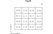
以下、ステップS22におけるビット値の算出方法について図8を参照して説明する。図8は、4×4のピクセルを含んでいる領域a1を示す図である。(Example of calculation method of bit value in step S22)
A method of calculating the bit value in step S22 will be described below with reference to FIG. FIG. 8 shows an area a1 containing 4×4 pixels.
図8において、領域a1は、ピクセル(0,0)からピクセル(3,3)までの16ピクセルを含んでいる。図8において、ピクセル(0,n)、(1,n)、(2,n)、(3,n)は、X軸の正方向にこの順に並んでいる(nは、1から3までの任意の数字である)。ピクセル(m,0)、(m,1)、(m,2)、(m,3)は、Y軸の負方向にこの順に並んでいる(mは、1から3までの任意の数字である)。この場合、例えば、端末30は、以下に示す(方法1)、(方法2)、(方法3)、又は(方法4)等によってビット列を算出する。 In FIG. 8, area a1 includes 16 pixels from pixel (0,0) to pixel (3,3). In FIG. 8, pixels (0, n), (1, n), (2, n), and (3, n) are arranged in this order in the positive direction of the X axis (n is a number from 1 to 3). any number). Pixels (m,0), (m,1), (m,2), and (m,3) are arranged in this order in the negative direction of the Y-axis (m is any number from 1 to 3). be). In this case, for example, the terminal 30 calculates a bit string by (Method 1), (Method 2), (Method 3), or (Method 4) shown below.
(方法1)
領域a1のピクセルの内の、先頭のピクセルのRGB値を取り出して、ビット列に変換する。例えば、領域a1において先頭のピクセルは、ピクセル(0,0)である。従って、端末30は、ピクセル(0,0)のRGB値を取り出して、ビット列に変換する。例えば、領域a1においてピクセル(0,0)のRGB値が、RGB=(0,255,0)である場合、端末30は、領域a1を“010”のビット列に変換する。(Method 1)
The RGB values of the first pixel in the pixels of area a1 are taken out and converted into a bit string. For example, the leading pixel in area a1 is pixel (0,0). Therefore, terminal 30 takes the RGB values of pixel (0,0) and converts them to a bit string. For example, if the RGB value of pixel (0,0) in area a1 is RGB=(0,255,0), terminal 30 converts area a1 into a bit string of "010".
(方法2)
領域a1の中央付近に位置するピクセルのRGB値を取り出して、ビット列に変換する。例えば、図8に示す例において、ピクセル(1,1)、(2,1)、(1,2)、(2,2)が領域a1の中央付近に位置する。従って、端末30は、ピクセル(1,1)、(2,1)、(1,2)、(2,2)の内のいずれかのRGB値をビット列に変換する。例えば、端末30は、ピクセル(1,1)のRGB値を取り出して、ビット列に変換する。(Method 2)
The RGB values of the pixels located near the center of area a1 are extracted and converted into bit strings. For example, in the example shown in FIG. 8, pixels (1,1), (2,1), (1,2), and (2,2) are located near the center of area a1. Accordingly, terminal 30 converts the RGB values of any of pixels (1,1), (2,1), (1,2), (2,2) into a bit string. For example, terminal 30 takes the RGB values of pixel (1,1) and converts them to a bit string.
(方法3)
領域a1の中央付近に位置するピクセルのRGB値を取り出して平均化し、平均化されたRGB値をビット列に変換する。例えば、ピクセル(1,1)のRGBが(255,0,253)であり、ピクセル(2,1)のRGBが(252,0,252)であり、ピクセル(1,2)のRGBが(252,0,252)であり、且つ、ピクセル(2,2)のRGBが(253,0,255)である場合、RGBの平均は、RGB=(253,0,253)である。この場合、端末30は、例えば、128以上のRGB値をビット:1に変換し、且つ、127以下のRGB値をビット:0に変換する。従って、端末30は、RGB=(253,0,253)を、“101”のビット列に変換する。(Method 3)
The RGB values of pixels positioned near the center of area a1 are taken out and averaged, and the averaged RGB values are converted into a bit string. For example, the RGB of pixel (1,1) is (255,0,253), the RGB of pixel (2,1) is (252,0,252), and the RGB of pixel (1,2) is ( 252,0,252) and the RGB of pixel (2,2) is (253,0,255), then the average of RGB is RGB=(253,0,253). In this case, the terminal 30, for example, converts RGB values of 128 or more to bits:1, and converts RGB values of 127 or less to bits:0. Therefore, the terminal 30 converts RGB=(253, 0, 253) into a bit string of "101".
(方法4)
4×4のピクセルの全てのRGB値を取り出して平均する。なお、複数のピクセルのRGB値を平均する方法は、(方法3)と同じであるため、説明を省略する。(Method 4)
Take all the RGB values of the 4x4 pixels and average them. Note that the method of averaging the RGB values of a plurality of pixels is the same as (Method 3), so the description is omitted.
(方法3)又は(方法4)のように、複数ピクセルのRGB値を平均化した場合、圧縮時に発生したノイズ等によってピクセルの一部のRGB値が変化していた場合であっても、正常に復元できる可能性が高くなる。 When the RGB values of multiple pixels are averaged as in (Method 3) or (Method 4), even if the RGB values of some pixels have changed due to noise generated during compression, normal more likely to be restored to
なお、端末30が、GPU(Graphics Processing Unit)を備えていてもよい。この場合、GPUが上記に示したビット値の算出処理を行ってもよい。GPUは、画像処理に係る計算の速度が速い。従って、端末30が第2映像信号Vd2を読み込んでいるときに、復号処理に遅延が発生しにくい。このため、リアルタイム性が必要な動画の配信において、遅延を発生させることなく動画の配信を行うことが可能となる。 Note that the terminal 30 may include a GPU (Graphics Processing Unit). In this case, the GPU may perform the bit value calculation processing described above. The GPU has a high calculation speed for image processing. Therefore, when the terminal 30 is reading the second video signal Vd2, the decoding process is less likely to be delayed. Therefore, when distributing moving images that require real-time performance, it is possible to distribute moving images without delay.
(第1実施形態の効果)
映像信号処理装置20によれば、映像信号及び映像信号とは異なるデータの両方を、1つの映像信号として配信することができる。より詳細には、処理部201は、受け付けた第1映像信号Vd1のうち領域a1~a6のピクセルのRGB値を第1データD1に基づくRGB値に置換することによって第2映像信号Vd2を生成する。これにより、映像信号処理装置20は、第1映像信号Vd1内に第1データD1(映像とは異なるデータ)が埋め込まれた第2映像信号Vd2を生成することが出来る。既存の動画配信プラットフォームは、映像信号である第2映像信号Vd2を配信することが出来る。そして、配信された映像信号を受信した端末30は、第1データD1を復号し、第1データD1に基づいて、所定の処理を実行することが出来る。例えば、第1データD1に照明データが含まれていた場合、端末30は、照明データに基づいて照明を制御できる。これにより、端末30は、例えば、パプリックビューイング会場の照明を配信元のライブ会場の照明と同じ様に制御できる。結果、ユーザは、ライブ会場と同じ様に制御された照明の元で、ライブ会場の撮影動画を見ることが出来る。このように、配信者は、既存の動画配信プラットフォームを用いて、映像信号及び映像信号とは異なるデータの両方を配信することができる。(Effect of the first embodiment)
According to the video
端末30は、映像信号の再生処理と、映像信号の再生とは異なる処理と、を同期して実行することができる。具体的には、第2映像信号Vd2は、1つの映像フレーム内に、そのフレームに同期して再生されるデータ(すなわち、第1データD1)が存在する。従って、端末30は、第2映像信号Vd2の各フレームを読み込んだとき、各フレームに埋め込まれている第1データD1を同時に読み込む。そして、端末30は、第2映像信号Vd2によって再生される映像の各フレームと同じタイミングで第1データD1に係る処理を実行する。これにより、端末30は、映像信号の再生処理と、映像信号に関係する処理(例えば、照明の制御)と、を同期して実行することができる。 The terminal 30 can synchronously execute a video signal reproduction process and a process different from the video signal reproduction. Specifically, in the second video signal Vd2, one video frame contains data (that is, the first data D1) that is reproduced in synchronization with that frame. Therefore, when the terminal 30 reads each frame of the second video signal Vd2, it simultaneously reads the first data D1 embedded in each frame. Then, the terminal 30 executes processing related to the first data D1 at the same timing as each frame of the video reproduced by the second video signal Vd2. As a result, the terminal 30 can synchronously execute video signal reproduction processing and video signal-related processing (for example, lighting control).
特に、第1データD1が、照明データを含んでいる場合、第2映像信号Vd2に基づいて表示される映像と、照明の動作(例えば、点灯、点滅、輝度の調整等)とが、同期する。そこで、例えば、配信者は、第1映像信号Vd1としてライブ演奏シーンの映像を準備する。同様にして、配信者は、照明データが含まれている第1データD1を準備する。そして、配信者は、映像信号処理装置20を用いて、照明データ(第1データ)を第1映像信号Vd1に埋め込むことによって第2映像信号Vd2を生成する。これにより、端末30が第2映像信号Vd2を読み込んだときに、端末30は、ライブ演奏に合わせて照明を制御する。従って、視聴者がライブ会場以外の場所にいる場合でも、ライブ会場においてライブを見ているような臨場感を得ることが出来る。 In particular, when the first data D1 includes lighting data, the video displayed based on the second video signal Vd2 and the lighting operation (for example, lighting, blinking, brightness adjustment, etc.) are synchronized. . Therefore, for example, the distributor prepares a video of a live performance scene as the first video signal Vd1. Similarly, the distributor prepares first data D1 containing lighting data. Then, the distributor uses the video
映像信号(画像)にデータを埋め込む場合、例えば、電子透かしによって、画像にデータを埋め込む方法がある。電子透かしの場合、映像信号にデータを埋め込む処理に加えて、埋め込まれたデータを隠蔽する等の追加処理が行われる。従って、電子透かしによって映像信号埋め込まれたデータを読み込む場合、端末は、埋め込まれたデータを読み込むアルゴリズム、及び、隠ぺいされた情報の解析等のアルゴリズム(以下、アルゴリズムV1と称す)を実行する必要がある。 When embedding data in a video signal (image), for example, there is a method of embedding data in an image by using an electronic watermark. In the case of electronic watermarking, in addition to the process of embedding data in a video signal, additional processes such as concealing the embedded data are performed. Therefore, when reading the data embedded in the video signal with the electronic watermark, the terminal needs to execute an algorithm for reading the embedded data and an algorithm for analyzing hidden information (hereinafter referred to as algorithm V1). be.
一方、本実施形態において、処理部201は、第1映像信号Vd1のうち領域a1~a6のピクセルのRGB値を第2データD2のRGB値に置換することによって第2映像信号Vd2を生成する。この場合、端末30は、復号においてRGB値に基づいたビット値を読み取る。ここで、RGB値をビット値に変換するアルゴリズムは、アルゴリズムV1と比較して複雑ではない。従って、第2データD2の復号処理で生じる計算負荷は、アルゴリズムV1よりも低い。これにより、端末30が第2映像信号Vd2を読み込んでいるときに、復号処理に遅延が発生しにくい。このため、リアルタイム性が必要な動画の配信において本実施形態の映像信号処理方法は、既存の電子透かし等よりも低い遅延で配信および再生処理を行うことが出来る。 On the other hand, in the present embodiment, the
(映像信号処理装置20の変形例1)
以下、変形例1に係る映像信号処理装置20aについて説明する。映像信号処理装置20aの処理部201a(図示せず)は、第2映像信号Vd2をある圧縮ブロック単位で圧縮する。ここで、領域a1~a6のピクセル数は、第2映像信号Vd2の圧縮ブロック単位のピクセル数と同一である。例えば、処理部201aの圧縮ブロック単位が8ピクセルである場合、処理部201aは、領域a1~a6のそれぞれのピクセル数を8ピクセルに設定する。そして、処理部201aは、第2映像信号Vd2を8ピクセルの圧縮ブロック単位で圧縮する。(
A video signal processing device 20a according to
(変形例1の効果)
映像信号処理装置20によれば、第2映像信号Vd2は、圧縮の影響を受けにくい。圧縮ブロック単位のピクセル数と、置換する各領域のピクセル数とが異なる場合、例えば、処理部は、領域a1と領域a2とを混合して圧縮する。この場合、領域a1のピクセルのRGB値の情報と領域a2のピクセルのRGB値の情報とが混合され、それぞれの領域の情報が失われる。従って、復号時に領域a1及び領域a2のピクセルのRGB値がそれぞれ圧縮前のRGB値に戻らない可能性がある。一方、本変形例では、領域a1~a6のピクセル数は、第2映像信号Vd2の圧縮ブロック単位のピクセル数と同一である。例えば、第2映像信号Vd2の圧縮ブロック単位が8ピクセルである場合、領域a1~a6のRGB値は8ピクセルである。この場合、例えば、処理部201aは、領域a1と領域a2とを混合して圧縮しない。従って、領域a1及び領域a2のピクセルのRGB値の情報がそれぞれ失われることなく、復号時に領域a1及び領域a2のピクセルのRGB値が復号前のRGB値に戻る。(Effect of Modification 1)
According to the video
(映像信号処理装置20の変形例2)
以下、映像信号処理装置20の変形例2に係る映像信号処理装置20bについて、図3を準用して説明する。映像信号処理装置20bは、第2映像信号Vd2を、フレーム毎に独立して圧縮する。(Modification 2 of video signal processing device 20)
A video signal processing device 20b according to Modification 2 of the video
本変形例では、映像信号処理装置20bの処理部201b(図示せず)は、2以上のフレームそれぞれの領域a1~a6のRGB値を第2データD2のRGB値で置換する。そして、処理部201bは、第2映像信号Vd2に含まれるそれぞれのフレームを独立して圧縮する。換言すれば、図3に示す第1フレーム300をフレーム内圧縮し、且つ、図3に示す第2フレーム301をフレーム内圧縮する。例えば、処理部201bは、第1フレーム300及び第2フレーム301のそれぞれの領域a1~a6のRGB値を第2データD2のRGB値で置換する。そして、処理部201bは、第1フレーム300と第2フレーム301とをそれぞれ独立して圧縮する。通信インタフェース202は、圧縮後の第2映像信号Vd2を出力する。 In this modification, the processing unit 201b (not shown) of the video signal processing device 20b replaces the RGB values of the regions a1 to a6 of each of two or more frames with the RGB values of the second data D2. Then, the processing unit 201b independently compresses each frame included in the second video signal Vd2. In other words, the
(変形例2の効果)
本変形例では、2以上のフレームそれぞれの領域a1~a6のRGB値が独立して置換されている。第2映像信号Vd2を圧縮する方法として、フレーム間圧縮がある。フレーム間圧縮は、隣り合うフレームのデータにおける差分のみを記録する圧縮方法である。すなわち、フレーム間圧縮は、複数のフレーム間においてRGB値が異なる箇所のみを抽出して圧縮する。すなわち、フレーム間圧縮によって第2映像信号Vd2を圧縮したとき、仮に同じピクセルにおいて同じRGB値のデータが埋め込まれた場合、埋め込まれたデータが消失してしまう可能性がある。これにより、復号時にピクセルのRGB値が、エンコード前の状態に戻らない可能性がある。(Effect of modification 2)
In this modified example, the RGB values of the regions a1 to a6 of each of two or more frames are replaced independently. As a method of compressing the second video signal Vd2, there is inter-frame compression. Interframe compression is a compression method that records only the differences in the data of adjacent frames. That is, inter-frame compression extracts and compresses only portions where RGB values are different between a plurality of frames. That is, when the second video signal Vd2 is compressed by inter-frame compression, if data of the same RGB values are embedded in the same pixel, the embedded data may disappear. This may result in the pixel's RGB values not returning to their pre-encoding state when decoded.
一方、処理部201bは、第2映像信号Vd2に含まれるそれぞれのフレームを独立して圧縮する。この場合、フレーム間圧縮とは異なり、第2映像信号Vd2に埋め込まれたデータ(RGB値を置換することによって埋め込まれたデータ)が消失する可能性は低い。従って、端末30が、第1データD1を正しく復号出来る可能性が高くなる。 On the other hand, the processing unit 201b independently compresses each frame included in the second video signal Vd2. In this case, unlike inter-frame compression, the data embedded in the second video signal Vd2 (data embedded by replacing the RGB values) is less likely to be lost. Therefore, the terminal 30 is more likely to be able to correctly decode the first data D1.
(映像信号処理装置20の変形例3)
以下、変形例3に係る映像信号処理装置20cについて図を参照しながら説明する。図9は、識別子データIDが含まれている第1データD1の変換の一例を示す図である。なお、図9では、領域a6の記載を省略した。映像信号処理装置20cは、識別子データIDが含まれている第1データD1に基づいて第2映像信号Vd2を生成する点で、映像信号処理装置20と異なる。以下、詳細に説明する。(Modification 3 of video signal processing device 20)
A video signal processing device 20c according to Modification 3 will be described below with reference to the drawings. FIG. 9 is a diagram showing an example of conversion of the first data D1 containing the identifier data ID. In addition, description of the area|region a6 is abbreviate|omitted in FIG. The video signal processing device 20c differs from the video
映像信号処理装置20cの処理部201c(図示せず)は、例えば、照明データCDに識別子データIDを付加することによって第1データD1を生成する(図9参照)。識別子データIDは、第1データD1が第2映像信号Vd2に埋め込まれているか否か(第2映像信号Vd2が、第2データを含んでいるか否か)を判定するためのデータである。すなわち、第1データD1は、第1データD1が埋め込まれていることを識別するための識別子データIDを含んでいる。第1データD1が識別子データIDを含んでいる場合、第2映像信号Vd2は、本実施形態の映像処理方法によって生成されていると判別可能である。本変形例では、第1データD1は、最上位ビットから、識別子データID、照明データCDの順に並んでいる(図9参照)。図9に示す例では、識別子データIDは、“0x55”というバイト値である。 The processing unit 201c (not shown) of the video signal processing device 20c generates the first data D1 by, for example, adding the identifier data ID to the illumination data CD (see FIG. 9). The identifier data ID is data for determining whether or not the first data D1 is embedded in the second video signal Vd2 (whether or not the second video signal Vd2 contains the second data). That is, the first data D1 includes identifier data ID for identifying that the first data D1 is embedded. When the first data D1 contains the identifier data ID, it can be determined that the second video signal Vd2 is generated by the video processing method of this embodiment. In this modification, the first data D1 is arranged in the order of the identifier data ID and the illumination data CD from the most significant bit (see FIG. 9). In the example shown in FIG. 9, the identifier data ID is a byte value of "0x55".
処理部201cは、識別子データが含まれた第1データD1を第2データD2に変換する。なお、処理部201cが第1データD1を第2データD2に変換した後の映像信号処理装置20cにおける処理は、映像信号処理装置20と同じであるため、説明を省略する。 The processing unit 201c converts the first data D1 containing the identifier data into the second data D2. Note that the processing in the video signal processing device 20c after the processing unit 201c converts the first data D1 into the second data D2 is the same as that in the video
(変形例3における復号処理の一例)
以下、変形例3において端末30が実行する復号処理の一例について図10を参照しながら説明する。図10は、変形例3において端末30が実行する復号処理の一例を示すフローチャートである。(An example of decoding processing in modified example 3)
An example of the decoding process executed by the terminal 30 in Modification 3 will be described below with reference to FIG. FIG. 10 is a flowchart showing an example of decoding processing executed by the terminal 30 in Modification 3. As shown in FIG.
本変形例では、ステップS21の後、端末30は、第2映像信号Vd2に識別子データIDが含まれているか否かを判定する(図10:ステップS32)。例えば、図9に示す例において、RGB値に置換された識別子データIDは、領域a1,a2,a3のそれぞれに埋め込まれる。従って、端末30は、領域a1,a2,a3のそれぞれのRGB値をビット値に変換する。そして、端末30は、変換後のビット値の内の先頭8ビットの値を取り出す。これにより、第2映像信号Vd2に識別子データIDが含まれているか否かを判定する。すなわち、端末30は、第1領域FAが含んでいる領域の内の少なくとも3つの領域のRGB値を取り出すことによって、第2映像信号Vd2に識別子データIDが含まれているか否かを判定することができる。 In this modification, after step S21, the terminal 30 determines whether or not the identifier data ID is included in the second video signal Vd2 ( FIG. 10 : step S32). For example, in the example shown in FIG. 9, identifier data ID replaced with RGB values are embedded in areas a1, a2, and a3. Therefore, the terminal 30 converts the RGB values of the areas a1, a2 and a3 into bit values. Then, the terminal 30 extracts the leading 8-bit value from the converted bit value. Thereby, it is determined whether or not the identifier data ID is included in the second video signal Vd2. That is, the terminal 30 determines whether or not the identifier data ID is included in the second video signal Vd2 by extracting the RGB values of at least three areas among the areas included in the first area FA. can be done.
端末30が第2映像信号Vd2に識別子データIDが含まれていると判定した場合(図10:ステップS32 Yes)、端末30は、第2映像信号Vd2における領域a1~a6のピクセルのRGB値に基づいて第1データD1の復号を行う(図10:ステップS33)。 When the terminal 30 determines that the identifier data ID is included in the second video signal Vd2 ( FIG. 10 : Yes in step S32), the terminal 30 sets the RGB values of the pixels in the areas a1 to a6 in the second video signal Vd2 to Based on this, the first data D1 is decoded ( FIG. 10 : step S33).
端末30が、第2映像信号Vd2に識別子データIDが含まれていないと判定した場合(図10:ステップS32 No)、端末30は第1データD1の復号を行わない(図10:ステップS33)。ステップS33の後、端末30はステップS24を実行する。 When the terminal 30 determines that the identifier data ID is not included in the second video signal Vd2 (FIG. 10: step S32 No), the terminal 30 does not decode the first data D1 (FIG. 10: step S33). . After step S33, the terminal 30 executes step S24.
(変形例3の効果)
映像信号処理装置20cは、識別子データIDが格納されたデータブロックを最初に復号する。そして、端末30は、第2映像信号Vd2に識別子データIDが格納されていなければ第1データD1の復号処理を行わないため、不要な復号処理を行わない。より詳細には、端末30が第2映像信号Vd2に識別子データIDが含まれていると判定した場合、端末30は第2映像信号Vd2における領域a1~a6のピクセルのRGB値に基づいて第1データD1の復号を行う。従って、第1データD1の復号が不要な場合、端末30は、第1データD1を復号する処理を実行することなく、入力した映像信号の再生のみを行うことが出来る。(Effect of modification 3)
The video signal processing device 20c first decodes the data block in which the identifier data ID is stored. If the identifier data ID is not stored in the second video signal Vd2, the terminal 30 does not perform decoding processing of the first data D1, and thus does not perform unnecessary decoding processing. More specifically, when the terminal 30 determines that the identifier data ID is included in the second video signal Vd2, the terminal 30 determines a first Data D1 is decrypted. Therefore, when the decoding of the first data D1 is unnecessary, the terminal 30 can only reproduce the input video signal without executing the process of decoding the first data D1.
(映像信号処理装置20の変形例4)
以下、変形例4に係る映像信号処理装置20dについて図11を参照しながら説明する。図11は、映像信号処理装置20dにおける処理の一例を示す図である。映像信号処理装置20aは、第1映像信号Vd1に基づいて表示される映像のサイズを拡張する点で、映像信号処理装置20と異なる。(Modification 4 of video signal processing device 20)
A video signal processing device 20d according to Modification 4 will be described below with reference to FIG. FIG. 11 is a diagram showing an example of processing in the video signal processing device 20d. The video signal processing device 20a differs from the video
図3と同様にして、図11において第1フレーム300における領域a1~a6が並ぶ方向を、X軸方向と定義する。また、第1フレーム300におけるX軸方向と直交する方向を、Y軸方向と定義する。 Similarly to FIG. 3, the direction in which the regions a1 to a6 in the
映像信号処理装置20dは、処理部201の代わりに処理部201d(図示せず)を備えている。処理部201dは、第1映像信号Vd1のピクセル数の拡張を行う。例えば、処理部201dは、図11に示すように、第1フレーム300のY軸方向のピクセル数を拡張する。例えば、処理部201dは、第1映像信号Vd1のピクセル数を、1280×720から1280×724へと拡張する。これにより、図11に示すように、第1映像信号Vd1は、拡張前の領域AA及び拡張された領域EAを有する。処理部201dは、第1映像信号Vd1における拡張された領域EAを領域a1~a6として指定する。そして、処理部201dは、領域a1~a6として指定された領域EAのピクセルのRGB値を第2データD2のRGB値に置換する。例えば、処理部201dが第1映像信号Vd1のピクセル数を、1280×720から1280×724へと拡張した場合、処理部201dは、拡張された1280×4のピクセルのうち4×4ピクセルずつ、合計で320個の領域を置換用の領域に指定する。 The video signal processing device 20d includes a processing section 201d (not shown) instead of the
上記に示す例の場合、拡張された1280×4の領域におけるピクセルのRGB値が置換される。この場合、処理部201dは、元の映像信号(変換前の第1映像信号Vd1)のピクセルのRGB値が置換することなく、元の映像信号を領域AAに表示する。すなわち、元の映像信号(変換前の第1映像信号Vd1)の一部のピクセルのRGB値を置換しなくて良い。すなわち、ピクセルを拡張することによって、元の画像(第1映像信号に基づいた映像)を保持することができる。 For the example shown above, the RGB values of the pixels in the expanded 1280x4 region are replaced. In this case, the processing unit 201d displays the original video signal in the area AA without replacing the RGB values of the pixels of the original video signal (first video signal Vd1 before conversion). That is, it is not necessary to replace the RGB values of some pixels of the original video signal (the first video signal Vd1 before conversion). That is, by extending the pixels, the original image (image based on the first video signal) can be retained.
(変形例4における復号処理の一例)
以下、変形例4において端末30が実行する復号処理の一例について図12を参照しながら説明する。図12は、変形例4において端末30が実行する復号処理の一例を示すフローチャートである。(An example of decoding processing in modification 4)
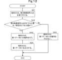
An example of the decoding process executed by the terminal 30 in Modification 4 will be described below with reference to FIG. FIG. 12 is a flowchart showing an example of decoding processing executed by the terminal 30 in Modification 4. As shown in FIG.
本変形例では、端末30は、第2映像信号Vd2のピクセル数を参照することによって第2映像信号Vd2を復号するか否かを判定する。具体的には、ステップS21の後、端末30は、第2映像信号Vd2のピクセル数が特定のピクセル数であるか否かを判定する(図12:ステップS42)。端末30が、第2映像信号Vd2のピクセル数は特定のピクセル数であると判定した場合(図12:ステップS42 Yes)、端末30は第2映像信号Vd2における領域a1~a6のRGB値に基づいて第1データD1の復号を行う(図12:ステップS43)。例えば、映像信号処理装置20aにおいて第1映像信号Vd1のピクセル数を1280×724に拡張する設定がされている場合、端末30は、第2映像信号Vd2のピクセル数が1280×724であるか否かを判定する。そして、端末30が、第2映像信号Vd2のピクセル数が1280×724であると判定した場合、端末30は、第2映像信号Vd2における領域a1~a6のRGB値に基づいて第1データD1の復号を行う。端末30は、復号された第1データD1を出力する(図12:ステップS24)。 In this modification, the terminal 30 determines whether or not to decode the second video signal Vd2 by referring to the number of pixels of the second video signal Vd2. Specifically, after step S21, the terminal 30 determines whether or not the number of pixels of the second video signal Vd2 is a specific number of pixels ( FIG. 12 : step S42). When the terminal 30 determines that the number of pixels in the second video signal Vd2 is the specific number of pixels ( FIG. 12 : Yes in step S42), the terminal 30 determines the RGB values of the areas a1 to a6 in the second video signal Vd2. to decode the first data D1 ( FIG. 12 : step S43). For example, when the video signal processing device 20a is set to expand the number of pixels of the first video signal Vd1 to 1280×724, the terminal 30 determines whether the number of pixels of the second video signal Vd2 is 1280×724. determine whether Then, when the terminal 30 determines that the number of pixels of the second video signal Vd2 is 1280×724, the terminal 30 converts the first data D1 based on the RGB values of the regions a1 to a6 in the second video signal Vd2. Decrypt. The terminal 30 outputs the decoded first data D1 (FIG. 12: step S24).
端末30が、第2映像信号Vd2のピクセル数は特定のピクセル数ではないと判定した場合(図12:ステップS42 No)、端末30は第2映像信号Vd2における領域a1~a6のRGB値に基づいて第1データD1の復号を行わない(図12:ステップS44)。 When the terminal 30 determines that the number of pixels of the second video signal Vd2 is not the specific number of pixels ( FIG. 12 : step S42 No), the terminal 30 determines the RGB values of the areas a1 to a6 in the second video signal Vd2. Then, the first data D1 is not decoded (FIG. 12: step S44).
(復号処理に係る変形例4の効果)
映像信号処理装置20dは、端末30に対して不要な復号処理を行わせないようにすることが出来る。具体的には、端末30は、第2映像信号Vd2のピクセル数が特定のピクセル数である場合にのみ第1データD1の復号を行う。従って、第2映像信号Vd2のピクセル数は特定のピクセル数でない場合は、端末30は、第1データD1の復号を行わない。従って、端末30が不要な処理を実行しなくなる。(Effect of modification 4 related to decryption processing)
The video signal processing device 20d can prevent the terminal 30 from performing unnecessary decoding processing. Specifically, the terminal 30 decodes the first data D1 only when the number of pixels of the second video signal Vd2 is a specific number of pixels. Therefore, if the number of pixels of the second video signal Vd2 is not the specific number of pixels, the terminal 30 does not decode the first data D1. Therefore, the terminal 30 does not execute unnecessary processing.
(映像信号処理装置20の変形例5)
以下、変形例5に係る映像信号処理装置20eについて図13を参照しながら説明する。図13は、映像信号処理装置20eにおける処理の一例を示す図である。映像信号処理装置20eは、領域a1~a6と合わせて、第2領域SAのピクセルのRGB値を変換する点で、映像信号処理装置20と異なる。(Modification 5 of video signal processing device 20)
A video signal processing device 20e according to Modification 5 will be described below with reference to FIG. FIG. 13 is a diagram showing an example of processing in the video signal processing device 20e. The video signal processing device 20e differs from the video
映像信号処理装置20eの処理部201e(図示せず)は、図13に示す様に、第2領域SAを指定する。第2領域SAは、領域a1~a6と重なっていない。第2領域SAの一部は、領域a1~a6の一部と接している。処理部201fは、第2領域SAのピクセルのRGB値を単一のRGB値(例えば、RGB=(0,0,0)等)に設定する。 The processing unit 201e (not shown) of the video signal processing device 20e designates the second area SA as shown in FIG. The second area SA does not overlap the areas a1 to a6. Part of the second area SA is in contact with parts of the areas a1 to a6. The processing unit 201f sets the RGB values of the pixels in the second area SA to a single RGB value (eg, RGB=(0, 0, 0), etc.).
また、処理部201fは、領域a1~a6及び第2領域SA以外の領域を第3領域TAとして指定する。このとき、第2領域SAは、領域a1~a6と、第3領域TAとの間に存在する。第3領域TAには、映像が再生される。すなわち、第3領域のRGB値は、フレーム毎に変化する可能性が高い。このため、第2映像信号Vd2の生成するときに、領域a1~a6と第3領域TAとが接している場合、第3領域TAのRGB値がノイズとなり、領域a1~a6のRGB値に影響を与える可能性がある。一方、本変形例では、領域a1~a6は、第2領域SAに接している。第2領域SAのピクセルのRGB値は、単一であるため、第2領域SAのRGB値がノイズとなって領域a1~a6のRGB値に影響を与える可能性は低い。 Also, the processing unit 201f designates an area other than the areas a1 to a6 and the second area SA as a third area TA. At this time, the second area SA exists between the areas a1 to a6 and the third area TA. An image is reproduced in the third area TA. That is, the RGB values of the third area are highly likely to change from frame to frame. Therefore, if the areas a1 to a6 and the third area TA are in contact when the second video signal Vd2 is generated, the RGB values of the third area TA become noise and affect the RGB values of the areas a1 to a6. may give On the other hand, in this modified example, the regions a1 to a6 are in contact with the second region SA. Since pixels in the second area SA have a single RGB value, it is unlikely that the RGB values in the second area SA will become noise and affect the RGB values in the areas a1 to a6.
(端末30の処理の応用例1)
以下、端末30の処理の応用例1について図14を参照しながら説明する。図14は、端末30における処理の一例を示す図である。(Application example 1 of processing of terminal 30)
An application example 1 of the processing of the terminal 30 will be described below with reference to FIG. FIG. 14 is a diagram showing an example of processing in the terminal 30. As shown in FIG.
本応用例において、端末30は、第2映像信号Vd2を受け付ける。そして、端末30は、第2映像信号Vd2における領域a1~a6を除去することによって第3映像信号Vd3を生成する。図14に示す例において、処理部201bは、領域a1~a6を含んでいる第1領域FAを除去している。例えば、除去前の第2映像信号Vd2のピクセル数が1280×720である場合、且つ、領域a1~a6のピクセル数が1280×4である場合、処理部201bは、第2映像信号Vd2のピクセル数を1280×716に変更する。すなわち、処理部201bは、第2映像信号Vd2の解像度を変更する。 In this application example, the terminal 30 receives the second video signal Vd2. Then, the terminal 30 generates the third video signal Vd3 by removing the regions a1 to a6 in the second video signal Vd2. In the example shown in FIG. 14, the processing unit 201b removes the first area FA including areas a1 to a6. For example, when the number of pixels of the second video signal Vd2 before removal is 1280×720, and when the number of pixels of the regions a1 to a6 is 1280×4, the processing unit 201b removes the pixels of the second video signal Vd2 Change the number to 1280x716. That is, the processing unit 201b changes the resolution of the second video signal Vd2.
これにより、第3映像信号Vd3に基づいて表示される映像では、領域a1~a6が表示されない。すなわち、端末30は、RGB値が置換される前の映像信号(元の映像信号)に係る映像を表示する。従って、ユーザは、違和感を覚えることなく配信された動画を見ることができる。 As a result, the areas a1 to a6 are not displayed in the video displayed based on the third video signal Vd3. That is, the terminal 30 displays an image related to the image signal (original image signal) before the RGB values are replaced. Therefore, the user can watch the distributed video without feeling uncomfortable.
なお、本応用例において処理部201bは、必ずしも、第2映像信号Vd2の解像度を変更することによって領域a1~a6を除去しなくてよい。例えば、処理部201bは、領域a1~a6を含んでいる領域のRGB値を単一のRGB値に変更してもよい。例えば、領域a1~a6のピクセル数が1280×4である場合、処理部201bは、1280×4のそれぞれのピクセルのRGB値を、例えば、RGB値=(0,0,0)等に変更する。この場合、第2映像信号Vd2の解像度は、1280×720のままである。 In this application example, the processing unit 201b does not necessarily have to remove the regions a1 to a6 by changing the resolution of the second video signal Vd2. For example, the processing unit 201b may change the RGB values of the area including the areas a1 to a6 to a single RGB value. For example, when the number of pixels in the areas a1 to a6 is 1280×4, the processing unit 201b changes the RGB value of each pixel of 1280×4 to, for example, RGB value=(0, 0, 0). . In this case, the resolution of the second video signal Vd2 remains 1280×720.
(映像信号処理装置20,20a~20eの応用例1)
以下、映像信号処理装置20,20a~20eの応用例1について図を参照して説明する。図15は、映像信号処理装置20,20a~20eの応用例1を示す図である。応用例において、映像信号処理装置20,20a~20eは、VR(Virtual Reality)に係る第2映像信号Vd2を出力する。端末30は、第2映像信号Vd2に基づいてVR映像を再生する。この場合、端末30は、例えば、PC等である。そして、端末30は、PCのディスプレイ上に、仮想3D空間を表示する。以下、応用例に係る処理の詳細について詳細に説明する。(Application Example 1 of Video
Application Example 1 of the video
端末30は、例えば、予め自装置に記憶された仮想空間生成用データ(図示せず)に基づいて仮想空間VSを生成する(図15参照)。仮想空間生成用データとは、具体的には、仮想空間VSの形状(立方体、球体等の形状)、又は、大きさ(仮想空間VSの端の座標等)等を決めるデータである。例えば、仮想空間生成用データは、仮想空間VSのX軸方向における端の座標、仮想空間VSのY軸方向における端の座標及び仮想空間VSのZ軸方向における端の座標を含んでいる。図15は、一例として立方体形状の仮想空間VSを示している。仮想空間VSは、一例として図14中のG0を原点としたx=0~1、y=0~1、z=0~1の座標で表現されている。 The terminal 30 generates the virtual space VS based on, for example, virtual space generation data (not shown) stored in advance in the terminal 30 (see FIG. 15). The virtual space generation data is, specifically, data that determines the shape of the virtual space VS (shape such as a cube or a sphere) or the size (coordinates of the edge of the virtual space VS, etc.). For example, the virtual space generation data includes the coordinates of the end of the virtual space VS in the X-axis direction, the coordinates of the end of the virtual space VS in the Y-axis direction, and the coordinates of the end of the virtual space VS in the Z-axis direction. FIG. 15 shows a cubic virtual space VS as an example. As an example, the virtual space VS is represented by coordinates x=0 to 1, y=0 to 1, and z=0 to 1 with G0 in FIG. 14 as the origin.
本応用例では、第1データD1は、仮想空間VSの空間座標データSDを含んでいる。空間座標データSDは、仮想空間VS内に設置される仮想の物体であるオブジェクトOBJの位置情報を示すデータである。空間座標データSDは、例えば、オブジェクトOBJの位置、形状、又は、大きさ等を示すデータを含んでいる。端末30は、空間座標データSDに基づいて仮想空間VS内にオブジェクトOBJ(例えば、スクリーン及び照明)を配置する。換言すれば、第1データD1は、仮想空間VSに表示されるオブジェクトOBJの空間座標データSDを含んでいる。 In this application example, the first data D1 includes spatial coordinate data SD of the virtual space VS. The spatial coordinate data SD is data indicating position information of an object OBJ, which is a virtual object placed in the virtual space VS. Spatial coordinate data SD includes, for example, data indicating the position, shape, size, or the like of object OBJ. The terminal 30 arranges the object OBJ (for example, screen and lighting) in the virtual space VS based on the spatial coordinate data SD. In other words, the first data D1 includes spatial coordinate data SD of the object OBJ displayed in the virtual space VS.
端末30は、第2映像信号Vd2を復号することによって、第2映像信号Vd2から空間座標データSDを取得する。端末30は、空間座標データSDに基づいた表示を行う。例えば、端末30は、自装置に記憶された仮想空間生成用データに基づいて仮想空間VSを生成する。端末30は、第2映像信号に含まれている空間座標データSDを読み込む。そして、端末30は、空間座標データSDの座標に基づいて仮想空間VS内にオブジェクトOBJを配置する。このように、端末30は、第2映像信号Vd2に基づいた仮想空間VSの表示を行う。 The terminal 30 obtains the spatial coordinate data SD from the second video signal Vd2 by decoding the second video signal Vd2. The terminal 30 performs display based on the spatial coordinate data SD. For example, the terminal 30 generates the virtual space VS based on virtual space generation data stored in the terminal 30 itself. The terminal 30 reads the spatial coordinate data SD included in the second video signal. Then, the terminal 30 arranges the object OBJ in the virtual space VS based on the coordinates of the space coordinate data SD. Thus, the terminal 30 displays the virtual space VS based on the second video signal Vd2.
本応用例では、オブジェクトOBJは、例えば、仮想空間VS内で第2映像信号Vd2の表示を行うスクリーンSCを含んでいる。この場合、第1データD1は、スクリーンSCの位置を示す空間座標データSDを含んでいる。端末30は、スクリーンSCの座標等に基づいてスクリーンSCの表示を行う。換言すれば、端末30は、空間座標データSDに基づいてスクリーンSCを仮想空間VSに表示する。この場合、空間座標データSDは、スクリーンSCの対角位置の座標、スクリーンSCの中心座標、又は、スクリーンSCの大きさ等を含んでいる。例えば、空間座標データSDは、スクリーンSCの対角位置(左下LD:x1,y1,z1、左上LU:x2,y2,z2、右上RU:x3,y3,z3、右下RD:x4,y4,z4)の座標を含んでいる。空間座標データSDは、例えば、左下LD:(x1,y1,z1)=(0.2,1.0,0.4)、左上LU:(x2,y2,z2)=(0.2,1.0,0.7)、右上RU:(x3,y3,z3)=(0.8,1.0,0.7)、右下RD:(x4,y4,z4)=(0.8,1.0,0.4)の座標を含んでいる。これにより、端末30は、仮想空間VS内にスクリーンSCのオブジェクトを表示する。そして、端末30は、仮想空間VS内のスクリーンSCに第2映像信号Vd2に基づく映像を表示する。 In this application example, the object OBJ includes, for example, a screen SC that displays the second video signal Vd2 within the virtual space VS. In this case, the first data D1 includes spatial coordinate data SD indicating the position of the screen SC. The terminal 30 displays the screen SC based on the coordinates of the screen SC. In other words, the terminal 30 displays the screen SC in the virtual space VS based on the spatial coordinate data SD. In this case, the spatial coordinate data SD includes the diagonal position coordinates of the screen SC, the center coordinates of the screen SC, the size of the screen SC, and the like. For example, the spatial coordinate data SD is the diagonal position of the screen SC (bottom left LD: x1, y1, z1, top left LU: x2, y2, z2, top right RU: x3, y3, z3, bottom right RD: x4, y4, z4). The spatial coordinate data SD is, for example, lower left LD: (x1, y1, z1)=(0.2, 1.0, 0.4), upper left LU: (x2, y2, z2)=(0.2, 1) .0, 0.7), upper right RU: (x3, y3, z3) = (0.8, 1.0, 0.7), lower right RD: (x4, y4, z4) = (0.8, 1.0, 0.4). Thereby, the terminal 30 displays the object of the screen SC in the virtual space VS. Then, the terminal 30 displays an image based on the second image signal Vd2 on the screen SC within the virtual space VS.
また、オブジェクトOBJは、例えば、照明L1VR,L2VRの情報を含んでいる(図15参照)。照明L1VR,L2VRの情報は、例えば、照明の位置(座標)、又は、照明の向き等を含んでいる。端末30は、照明L1VR,L2VRの座標、又は、照明の向き等に基づいて照明L1VR,L2VRを仮想空間VS内に表示する。端末30は、第2映像信号Vd2に埋め込まれた照明データに基づいて照明L1VR,L2VRを制御(例えば、点灯、消灯、色の変更等)する。このため、例えば、配信者は、照明L1VR,L2VRの位置を、現実世界のライブ会場の照明の位置、又は、照明の向きに基づいて設定することによって現実世界のライブ会場の照明を再現することが出来る。これにより、視聴者は、単にライブ演奏の映像を見るだけでなく、あるライブハウスの中に居てライブ演奏を聞いているような臨場感を得ることができる。 Also, the object OBJ includes, for example, information on the lights L1VR and L2VR (see FIG. 15). The information of the lights L1VR and L2VR includes, for example, the position (coordinates) of the lights, or the direction of the lights. The terminal 30 displays the lights L1VR and L2VR in the virtual space VS based on the coordinates of the lights L1VR and L2VR or the directions of the lights. The terminal 30 controls (for example, turns on, turns off, changes colors, etc.) the lights L1VR and L2VR based on the lighting data embedded in the second video signal Vd2. For this reason, for example, the broadcaster can reproduce the lighting of the live venue in the real world by setting the positions of the lighting L1VR and L2VR based on the position of the lighting in the live venue in the real world or the direction of the lighting. can be done. As a result, the viewer can not only watch the video of the live performance, but also get the realism of being in a certain live house and listening to the live performance.
なお、照明L1VR,L2VRの情報は、例えば、照明のモデル名(照明の機種名)、又は、照明の機能(単色照明、又は、カラー照明等)に係る情報等を含んでいてもよい。この場合、端末30は、例えば、予め照明の3次元モデル画像を記憶している。照明の3次元モデル画像とは、現実世界の照明の形状、又は、色等を再現したモデル画像である。端末30が照明のモデル名、又は、照明の機能に係る情報を受信した場合、端末30は、照明のモデル名、又は、照明の機能に対応した照明の3次元モデル画像を選択する。端末30は、選択した照明の3次元モデル画像に基づいて仮想空間VS内に照明L1VR,L2VRを表示する。これにより、端末30は、現実世界の照明の形状等を再現した照明をL1VR,L2VRを仮想空間VS内に表示する。従って、配信者は、更にライブ会場の照明等を再現することができる。 The information on the lights L1VR and L2VR may include, for example, the model name of the lights (model name of the lights), or the information on the functions of the lights (monochromatic lighting, color lighting, etc.). In this case, the terminal 30 stores, for example, a three-dimensional model image of lighting in advance. A three-dimensional model image of lighting is a model image that reproduces the shape or color of lighting in the real world. When the terminal 30 receives the model name of the lighting or the information about the function of the lighting, the terminal 30 selects the model name of the lighting or the three-dimensional model image of the lighting corresponding to the function of the lighting. The terminal 30 displays the lights L1VR and L2VR in the virtual space VS based on the selected three-dimensional model image of the lights. As a result, the terminal 30 displays lighting L1VR and L2VR that reproduce the shape of the lighting in the real world in the virtual space VS. Therefore, the distributor can further reproduce the lighting and the like of the live venue.
端末30は、例えば、図15に示すように、仮想空間VSを俯瞰表示する。視聴者は、端末30を介して仮想空間VSに存在する仮想的なスクリーンSCを見ることができる。これにより、視聴者は、例えば、ライブ会場で行われるライブ演奏を俯瞰しているような臨場感を得ることができる。例えば、配信者は、第1映像信号Vd1としてライブの演奏シーンの映像を準備する。この場合、スクリーンSCには、ライブの演奏シーンが表示される。従って、視聴者は、仮想空間VS内において、ライブ演奏が行われている様子を視聴することができる。 For example, as shown in FIG. 15, the terminal 30 displays a bird's-eye view of the virtual space VS. A viewer can see a virtual screen SC existing in the virtual space VS via the
なお、空間座標データSDは、仮想空間VSにおける表示の原点を含んでいてもよい。仮想空間VSにおける表示の原点とは、例えば、図15の視聴者Gの視聴位置を示す情報であり、視聴者の視点の原点を示す情報である。空間座標データSDは、例えば、視聴者Gの視聴位置(視聴者Gの視点の原点)は、(x,y,z)=(0.1,0.6,0)であるという情報を含んでいる(例えば、図14に示す視聴者Gの位置)。この場合、端末30は、視聴位置:(x,y,z)=(0.1,0.6,0)からある方向(例えば、スクリーンSCの方向)を見る視点で仮想空間VSを表示する。換言すれば、端末30は、表示の原点に基づいて仮想空間VSの表示を行う。これにより、視聴者は、単にライブ演奏の映像を見るだけでなく、あるライブハウスの中に居てライブ演奏を聞いているような臨場感を得ることができる。 The spatial coordinate data SD may include the origin of display in the virtual space VS. The origin of display in the virtual space VS is, for example, information indicating the viewing position of the viewer G in FIG. 15, and information indicating the origin of the viewpoint of the viewer. The spatial coordinate data SD includes, for example, information that the viewing position of the viewer G (origin of the viewpoint of the viewer G) is (x, y, z)=(0.1, 0.6, 0). (for example, the position of the viewer G shown in FIG. 14). In this case, the terminal 30 displays the virtual space VS from the viewing position: (x, y, z)=(0.1, 0.6, 0) from a certain direction (for example, the direction of the screen SC). . In other words, the terminal 30 displays the virtual space VS based on the display origin. As a result, the viewer can not only watch the video of the live performance, but also get the realism of being in a certain live house and listening to the live performance.
なお、端末30は、視聴者の視聴位置、又は、視聴者の視点をフレーム毎に変化させてもよい。例えば、図15に示す例において、端末30は、視聴者Gの視聴位置を(x,y,z)=(0.1,0.6,0)から(x,y,z)=(0.7,0.6,0)へと切り替えてもよい。また、端末30は、フレーム毎に視聴者Gの視聴位置をX軸の正方向に少しずつ移動させてもよい。これにより、端末30は、ライブビデオにおけるカメラワークを再現したような映像の切り替え、又は、被写体の移動に応じたカメラの移動等を行うことが出来る。 Note that the terminal 30 may change the viewing position of the viewer or the viewpoint of the viewer for each frame. For example, in the example shown in FIG. 15, the terminal 30 changes the viewing position of the viewer G from (x, y, z)=(0.1, 0.6, 0) to (x, y, z)=(0 .7, 0.6, 0). Also, the terminal 30 may move the viewing position of the viewer G little by little in the positive direction of the X axis for each frame. As a result, the terminal 30 can perform switching of images that reproduce camera work in live video, or movement of the camera according to movement of the subject.
なお、本応用例において、第1データD1は、例えば、仮想空間VSに係る処理を実行する制御プログラム(以下、プログラムPと称す)を含んでいてもよい。例えば、映像信号処理装置20,20a~20eは、プログラムPを含んでいる第1データD1を第1映像信号Vd1に埋め込むことによって第2映像信号Vd2を生成する。端末30が第2映像信号Vd2を受信したとき、端末30は、第2映像信号Vd2に埋め込まれているプログラムPを読み込む。そして、端末30は、プログラムPを実行することによって、仮想空間VS、又は、オブジェクトOBJ等を生成する。なお、この場合、プログラムPは、例えば、HTML、又は、JavaScript(登録商標)等によって生成されている。 In this application example, the first data D1 may include, for example, a control program (hereinafter referred to as program P) that executes processing related to the virtual space VS. For example, the video
なお、第1データD1が、必ずしも、オブジェクトOBJとしてスクリーンSC及び照明L1VR,L2VRを含んでいなくてもよい。例えば、第1データD1がプログラムPを含んでいる場合、プログラムPが、スクリーンSC及び照明L1VR,L2VRの位置情報等を含んでいてもよい(スクリーンSC及び照明L1VR,L2VRの位置情報等が、プログラムPに埋め込まれていてもよい)。この場合、端末30がプログラムPを実行することによって、プログラムPに含まれているスクリーンSC及び照明L1VR,L2VRの位置情報等を読み込む。従って、配信者は、ライブ会場の照明位置、又は、照明の形状等を再現した照明のモデルをプログラムPに埋め込む。端末30は、プログラムPに埋め込まれた照明のモデルを読み込むことによって、仮想空間VS内にライブ会場の照明を再現した照明L1VR,L2VRを表示する。 Note that the first data D1 does not necessarily include the screen SC and the lights L1VR and L2VR as the objects OBJ. For example, when the first data D1 includes a program P, the program P may include positional information of the screen SC and the lights L1VR and L2VR (the positional information of the screen SC and the lights L1VR and L2VR may be may be embedded in program P). In this case, the terminal 30 executes the program P to read the positional information of the screen SC and the lights L1VR and L2VR included in the program P. FIG. Therefore, the distributor embeds in the program P a lighting model that reproduces the lighting position or the shape of the lighting at the live venue. By reading the lighting model embedded in the program P, the terminal 30 displays the lighting L1VR, L2VR that reproduces the lighting of the live venue in the virtual space VS.
(映像信号処理装置20,20a~20eの応用例2)
以下、映像信号処理装置20,20a~20eの応用例2について説明する。応用例2に係る映像信号処理装置20,20a~20eは、音響制御データを含んでいる第1データD1を受け付ける。映像信号処理装置20,20a~20eは、音響制御データを含んでいる第1データD1に基づいて第2映像信号Vd2を生成し、第2映像信号Vd2を端末30へ出力する。これにより、端末30は、音響制御データに基づいて再生する動画の音の制御を行う。音響制御データは、例えば、ボリューム値、エフェクト(例えば、イコライザー、又は、ディレイ等)の値、又は、音像定位処理に係るデータ等を含んでいる。例えば、音響制御データがボリューム値を含んでいる場合、端末30はボリューム値に応じて再生する動画の音量を増加、又は、減少させる。(Application example 2 of video
Application Example 2 of the video
(映像信号処理装置20,20a~20eの応用例3)
以下、映像信号処理装置20,20a~20eの応用例3について説明する。応用例3に係る映像信号処理装置20,20a~20eは、映像制御データを含んでいる第1データD1を受け付ける。映像信号処理装置20,20a~20eは、映像制御データを含んでいる第1データD1に基づいて第2映像信号Vd2を生成し、第2映像信号Vd2を端末30へ出力する。端末30は、映像制御データに基づいて再生する動画の制御を行う。映像制御データは、例えば、映像の分割に係るデータ、映像のエフェクト処理(例えば、画面ミュート、又は、明度調整等)に係るデータ、映像を表示するスクリーンに係るデータ、又は、演者の位置情報に係るデータ等を含んでいる。例えば、映像制御データが映像の明度に係るデータを含んでいる場合、端末30は、再生する動画の明るさを調整する。(Application Example 3 of Video
Application Example 3 of the video
また、映像制御データが映像の分割に係るデータを含んでいる場合、端末30は、例えば、分割データに従って映像を複数に分割等する。そして、端末30は、分割した映像のそれぞれを、異なるスクリーンに再生する。例えば、配信者は、ライブ会場において複数のカメラ(例えば、第1カメラ及び第2カメラ)を準備する。そして、配信者は、例えば、ライブの演奏シーンにおいて、第1カメラによってライブ会場のステージを撮影し、第2カメラによって演者の顔を撮影する。このとき、映像信号処理装置20,20a~20eは、第1カメラ及び第2カメラのそれぞれから映像信号を受け付ける。そして、映像信号処理装置20,20a~20eは、第1カメラから受け付けた映像信号(以下、第1カメラの映像信号と称す)及び第2カメラから受け付けた映像信号(以下、第2カメラの映像信号と称す)の両方を埋め込んだ第1映像信号Vd1(以下、分割用第1映像信号と称す)を生成する。 Also, when the video control data includes data relating to video division, the terminal 30 divides the video into a plurality of pieces according to the division data, for example. Then, the terminal 30 reproduces each divided video on a different screen. For example, the distributor prepares multiple cameras (for example, a first camera and a second camera) at the live venue. Then, for example, in a live performance scene, the distributor captures the stage of the live venue with the first camera, and captures the face of the performer with the second camera. At this time, the video
映像信号処理装置20,20a~20eは、分割用第1映像信号に基づいて第2映像信号Vd2を生成する。このとき、映像信号処理装置20,20a~20eは、複数のスクリーンの内のどのスクリーンに第1カメラの映像信号を表示するかを示す情報を第2映像信号Vd2に埋め込み、且つ、複数のスクリーンの内のどのスクリーンに第2カメラの映像信号を表示するかを示す情報を第2映像信号Vd2に埋め込む。例えば、映像信号処理装置20,20a~20eは、第1カメラの映像信号を第1スクリーンに表示するという情報(以下、第1情報と称す)と、第2カメラの映像信号を第2スクリーンに表示するという情報(以下、第2情報と称す)と、を第2映像信号Vd2に埋め込む。映像信号処理装置20,20a~20eは、第2映像信号Vd2を端末30へ出力する。 The video
端末30は、第2映像信号Vd2を第1カメラの映像信号と、第2カメラの映像信号とに分割する。端末30は、第1カメラの映像信号及び第2カメラの映像信号をそれぞれ異なるスクリーンに送信する。例えば、端末30は、ライブ会場のステージの映像(第1カメラの映像信号に基づく映像)を第1情報に基づいて第1スクリーンに表示し、且つ、演者の顔の映像(第2カメラの映像信号に基づく映像)を第2情報に基づいて第2スクリーンに表示する。 The terminal 30 splits the second video signal Vd2 into a first camera video signal and a second camera video signal. The terminal 30 transmits the video signal of the first camera and the video signal of the second camera to different screens. For example, the terminal 30 displays the image of the stage of the live venue (image based on the image signal of the first camera) on the first screen based on the first information, and displays the image of the face of the performer (image of the second camera). video based on the signal) is displayed on the second screen based on the second information.
なお、端末30は、例えば、第1カメラの映像信号と第2カメラの映像信号とを切り替えることによって1つのスクリーンに第1カメラの映像信号及び第2カメラの映像信号を表示してもよい。この場合、端末30のユーザは、第1カメラの映像信号と第2カメラの映像信号とを切り替える操作を、端末30を介して行ってもよい。 The terminal 30 may display the video signal of the first camera and the video signal of the second camera on one screen, for example, by switching between the video signal of the first camera and the video signal of the second camera. In this case, the user of the terminal 30 may perform an operation via the terminal 30 to switch between the video signal of the first camera and the video signal of the second camera.
なお、映像制御データは、カメラワークに係るデータを含んでいてもよい。カメラワークに係るデータとは、例えば、スクリーンに表示する映像信号の順番等である。例えば、映像制御データは、第1カメラの映像信号に基づいた映像、第2カメラの映像信号に基づいた映像、第1カメラの映像信号に基づいた映像を、この順に第1スクリーンに表示させるというデータを含んでいる。この場合、第1スクリーンは、第1カメラの映像信号に基づいた映像、第2カメラの映像信号に基づいた映像、第1カメラの映像信号に基づいた映像を、この順に表示する。 Note that the video control data may include data related to camera work. The data related to camera work is, for example, the order of video signals to be displayed on the screen. For example, the image control data is such that an image based on the image signal of the first camera, an image based on the image signal of the second camera, and an image based on the image signal of the first camera are displayed on the first screen in this order. contains data. In this case, the first screen displays an image based on the image signal of the first camera, an image based on the image signal of the second camera, and an image based on the image signal of the first camera in this order.
なお、応用例3において、第1データD1は、例えば、演者の位置データ等を含んでいてもよい。端末30は、演者の位置データに基づいて、演者の顔の映像を再生するスクリーンの位置を変化させてもよい。例えば、第1データD1は、演奏中の演者が移動した方向、又は、移動距離等の情報を含んでいる。この場合、端末30は、第1データD1を読み込むことによって演奏中の演者が移動した方向、又は、移動距離の情報を得る。そして、例えば、端末30は、演者が移動した方向と同じ方向に第2スクリーン(演者の顔の映像を再生するスクリーン)を移動させる。このとき、端末30は、演者の移動距離の情報に基づいて第2スクリーンの移動量を変化させる。なお、本応用例において、端末30は、演者の位置データに基づいて音像定位処理を行ってもよい。例えば、端末30は、演者C(図示せず)が移動した方向に演者Cの演奏によって生じた音が定位する音像定位処理を行ってもよい。 In addition, in the application example 3, the first data D1 may include, for example, the performer's position data. The terminal 30 may change the position of the screen that reproduces the image of the performer's face based on the performer's position data. For example, the first data D1 includes information such as the direction in which the performer moved during the performance, or the movement distance. In this case, the terminal 30 obtains information on the direction or distance of movement of the performer during the performance by reading the first data D1. Then, for example, the terminal 30 moves the second screen (the screen that reproduces the image of the performer's face) in the same direction as the performer's movement. At this time, the terminal 30 changes the amount of movement of the second screen based on the information on the movement distance of the performer. Note that, in this application example, the terminal 30 may perform sound image localization processing based on the performer's position data. For example, the terminal 30 may perform sound image localization processing to localize the sound produced by the performer C's performance in the direction in which the performer C (not shown) moved.
(映像信号処理装置20,20a~20eの応用例4)
以下、映像信号処理装置20,20a~20eの応用例4について説明する。応用例4に係る映像信号処理装置20,20a~20eは、第1データD1のデータタイプを示す情報を第2映像信号Vd2に埋め込む。データタイプとは、第1データD1の種類を識別するためのラベル情報である。データタイプは、例えば、第1データD1が音響制御データ、又は、映像制御データ等であることを示す情報である。すなわち、第1データD1は、第1データD1の種類を識別するためのラベル情報であるデータタイプを含んでいる。映像信号処理装置20,20a~20eは、データタイプを第2映像信号Vd2に埋め込む。端末30は、第2映像信号Vd2に埋め込まれているデータタイプを解析する。解析の結果、端末30が実行可能な制御データを示すデータタイプが第1データD1に含まれていると端末30が判定した場合、端末30は制御データに基づいた制御を行う。例えば、端末30に、音響制御用のアプリケーションがインストールされている場合、端末30は、第2映像信号Vd2に、音響制御データのデータタイプが含まれているか否かを判定する。端末30が、第2映像信号Vd2に音響制御データのデータタイプが含まれていると判定した場合、音響制御データに基づいて音響機器を制御する。(Application Example 4 of Video
Application Example 4 of the video
(その他の実施形態)
本発明に係る映像信号処理装置20,20a~20eに限らず、その要旨の範囲内において変更可能である。また、映像信号処理装置20,20a~20eの構成を任意に組み合わせてもよい。(Other embodiments)
The present invention is not limited to the video
なお、第1実施形態における映像信号処理装置20,20a~20eの処理は、図4に示す例のみに限定されない。処理部201は、例えば、第1映像信号Vd1を受け付けた後に、第1データD1を受け付けてもよい。また、例えば、処理部201は、第2データD2を生成した後に、第1映像信号Vd1を受け付けてもよい。 Note that the processing of the video
なお、映像信号処理装置20,20a~20eは、必ずしも、映像信号処理装置20とは異なる装置(以下、装置Xと称する)から、第1データD1及び第1映像信号Vd1受け付けなくてもよい(図示せず)。映像信号処理装置20,20a~20eは、例えば、自装置において第1データD1又は第1映像信号Vd1を生成してもよい。この場合、例えば、映像信号処理装置20,20a~20eには、第1データD1を生成するためのアプリケーションプログラム、又は、第1映像信号Vd1を生成するためのアプリケーションプログラムがインストールされている。 Note that the video
なお、第1映像信号Vd1が含んでいるフレームの数は、図3に示す2個の例に限定されない。 Note that the number of frames included in the first video signal Vd1 is not limited to the two examples shown in FIG.
なお、第1映像信号Vd1は、必ずしも、2以上のフレームを含んでいなくてもよい。第1映像信号Vd1は、1つのフレームのみを含んでいてもよい。この場合、第1映像信号Vd1は、写真等の静止画像である。 Note that the first video signal Vd1 does not necessarily include two or more frames. The first video signal Vd1 may contain only one frame. In this case, the first video signal Vd1 is a still image such as a photograph.
なお、第2映像信号Vd2の圧縮において圧縮率を上げずに圧縮することによって(高画質で圧縮することによって)、領域a1~a6と、領域a1~a6以外の領域と、の境界及びその近傍においてRGB値が変化しにくくなる。従って、第1データD1を正しく復号出来る可能性が高くなる。 By compressing the second video signal Vd2 without increasing the compression rate (compressing with high image quality), the boundary between the areas a1 to a6 and the areas other than the areas a1 to a6 and the vicinity thereof , the RGB values are less likely to change. Therefore, the possibility that the first data D1 can be correctly decoded increases.
なお、第1データD1のバイト値は、“0x11”,“0x13”以外の値であってもよい。 Note that the byte values of the first data D1 may be values other than "0x11" and "0x13".
なお、識別子データIDのバイト値は、“0x55”以外の値であってもよい。例えば、映像信号処理装置20,20a~20eは、例えば、映像信号において出現しにくいドットの組み合わせに基づいて識別子データIDのビット列を設定してもよい。例えば、4×4ピクセルの領域を1ドットと定義した場合、映像信号においてRGB=(255,0,0)のドットと、RGB=(0,255,0)のドットと、RGB(0,0,255)のドットとが、この順に並ぶ可能性は低い。従って、映像信号処理装置20,20a~20eは、領域a1のRGBが(255,0,0)となり、領域a2のRGBが(0,255,0)となり、且つ、領域a3のRGBが(0,0,255)となるように、識別子データIDのビット列を設定する。すなわち、映像信号処理装置20,20a~20eは、識別子データIDのビット列を“10001000”(すなわち、“0x88”)に設定してもよい。 Note that the byte value of the identifier data ID may be a value other than "0x55". For example, the video
なお、領域a1~a6のそれぞれのピクセル数は、必ずしも4ピクセルでなくてよい。例えば、領域a1~a6のそれぞれのピクセル数は、8ピクセル等であってもよい。 Note that the number of pixels in each of the regions a1 to a6 does not necessarily have to be 4 pixels. For example, the number of pixels in each of the regions a1 to a6 may be 8 pixels or the like.
なお、映像信号処理装置20,20a~20eは、必ずしも、第2領域SAを指定しなくてもよい。 Note that the video
なお、領域a1~a6のピクセル数は、必ずしも、第2映像信号Vd2の圧縮ブロック単位のピクセル数と同一でなくてもよい。 Note that the number of pixels in the regions a1 to a6 does not necessarily have to be the same as the number of pixels per compression block of the second video signal Vd2.
なお、映像信号処理装置20,20a~20eは、必ずしも、第2映像信号Vd2に含まれるそれぞれのフレームを独立して圧縮しなくてよい。 Note that the video
なお、第1データD1は、必ずしも照明データを含んでいなくてもよい。 Note that the first data D1 does not necessarily include illumination data.
なお、第1データD1は、必ずしも、空間座標データSDを含んでいなくてもよい。 Note that the first data D1 does not necessarily have to include the spatial coordinate data SD.
なお、オブジェクトOBJは、必ずしもスクリーンSCを含んでいなくてもよい。 Note that the object OBJ does not necessarily have to include the screen SC.
なお、応用例1においてオブジェクトOBJは、必ずしも2つの照明(照明L1VR,L2VR)の情報を含まなくてよい。例えば、オブジェクトOBJは、1つの照明の情報を含んでいてもよいし、オブジェクトOBJは、3以上の照明の情報を含んでいてもよい。 Note that in application example 1, the object OBJ does not necessarily include information on the two lights (lights L1VR and L2VR). For example, an object OBJ may contain information on one illumination, or may contain information on three or more illuminations.
なお、第1データD1は、必ずしも、第1映像信号Vd1のピクセル数の拡張を行わなくてよい。また、映像信号処理装置20,20a~20eは、必ずしも、第1映像信号Vd1における拡張された領域を領域a1~a6として指定しなくてもよい。 Note that the first data D1 does not necessarily have to expand the number of pixels of the first video signal Vd1. Also, the video
なお、映像信号処理装置20,20a~20eは、必ずしも、第2映像信号Vd2における領域a1~a6を除去することによって第3映像信号Vd3を生成しなくてもよい。 Note that the video
なお、端末30は、必ずしも、第2映像信号Vd2に識別子データIDが含まれているか否かを判定しなくてよい。この場合、端末30は、第2映像信号Vd2に識別子データIDが含まれていると判定した場合でなくても、第1データD1の復号を行ってよい。 Note that the terminal 30 does not necessarily have to determine whether or not the identifier data ID is included in the second video signal Vd2. In this case, the terminal 30 may decode the first data D1 even if it is not determined that the identifier data ID is included in the second video signal Vd2.
なお、端末30は、必ずしも、第2映像信号Vd2のピクセル数が特定のピクセル数であるか否かを判定しなくてよい。この場合、端末30は、ピクセル数が特定のピクセル数であると判定した場合でなくても、第1データD1の復号を行ってよい。 Note that the terminal 30 does not necessarily have to determine whether the number of pixels of the second video signal Vd2 is a specific number of pixels. In this case, the terminal 30 may decode the first data D1 even if it is not determined that the number of pixels is the specific number of pixels.
なお、第1データD1は、識別子データID以外のデータを更に含んでいてもよい。第1データD1は、例えば、データ数を示すデータ、又は、チェックサム等を含んでいてもよい。データ数を示すデータは、第1データD1のデータ数を記録したバイト列である。チェックサムは、端末30へ送信する前の第2映像信号Vd2と、端末30へ送信した後の第2映像信号Vd2とが、同じであるかを確認するためのデータである。例えば、映像信号処理装置20,20a~20eは、端末30へ送信する前の第1データD1のデータ列に基づいてチェックサムを算出する。また、映像信号処理装置20,20a~20eは、端末30へ送信した後の第1データD1のデータ列に基づいてチェックサムを算出する。このとき、端末30は、チェックサムが正しい場合に、第2映像信号Vd2の復号が正常に行われたと判定してよい。なお、第1データD1は、例えば、リードソロモン符号等の誤り訂正符号を含んでいてもよい。 Note that the first data D1 may further include data other than the identifier data ID. The first data D1 may include, for example, data indicating the number of data, or a checksum. The data indicating the number of data is a byte string recording the number of data of the first data D1. The checksum is data for confirming whether the second video signal Vd2 before transmission to the terminal 30 and the second video signal Vd2 after transmission to the terminal 30 are the same. For example, the video
なお、端末30は、識別子データIDに基づいて第1データD1の復号が正常に行えたか否かを判定してよい。端末30は、例えば、“0x55”のバイト値が復号できた場合に、第1データD1を正常に復号できたと判定する。一方、端末30が“0x55”のバイト値を復号できない場合、第1データD1を復号出来ないと判定する。 Note that the terminal 30 may determine whether or not the decoding of the first data D1 has been performed normally based on the identifier data ID. For example, when the byte value of "0x55" can be decoded, the terminal 30 determines that the first data D1 has been successfully decoded. On the other hand, when the terminal 30 cannot decode the byte value of "0x55", it determines that the first data D1 cannot be decoded.
なお、第1データD1は、応用例2において説明した音響制御データ、又は、応用例3において説明した映像制御データ以外のデータを含んでいてもよい。例えば、第1データD1は、PC等の制御データ(例えば、電源のオンオフ等の制御データ)、又は、家電コントローラの制御データ(例えば、カーテンの開閉データ、室内照明のオンオフの制御データ、または扇風機のオンオフ)等を含んでいてもよい。 The first data D1 may include data other than the audio control data described in the second application or the video control data described in the third application. For example, the first data D1 is control data for a PC or the like (for example, control data for turning on or off a power supply), or control data for a home appliance controller (for example, curtain opening/closing data, indoor lighting on/off control data, or a fan on/off), etc.
なお、変形例4において、端末30が拡張された領域EAを含んでいる第2映像信号Vd2を受信した場合、端末30は領域EAを除去してもよい。例えば、領域EAによって第2映像信号Vd2のピクセル数が1280×720から1280×724に拡張されていた場合、端末30は、第2映像信号Vd2のピクセル数を1280×720へと変更してもよい。すなわち、端末30は、第2映像信号Vd2の解像度を変更してもよい。または、端末30は、拡張された領域EAのRGB値を単一のRGB値に変更してもよい。端末30が、第2映像信号Vd2の解像度を変更することによって第2映像信号Vd2から拡張された領域EAを除去する場合、端末30は、元の映像信号(変換前の第1映像信号Vd1)を表示する。従って、端末30が第2映像信号Vd2の解像度を変更する場合は、端末30が領域EAのRGB値を単一のRGB値に変更する場合と比較して、ユーザは、違和感を覚えることなく配信された動画を見ることができる。 Note that in Modification 4, when the terminal 30 receives the second video signal Vd2 including the extended area EA, the terminal 30 may remove the area EA. For example, when the number of pixels of the second video signal Vd2 is expanded from 1280×720 to 1280×724 by the area EA, the terminal 30 changes the number of pixels of the second video signal Vd2 to 1280×720. good. That is, the terminal 30 may change the resolution of the second video signal Vd2. Alternatively, terminal 30 may change the RGB values of extended area EA to a single RGB value. When the terminal 30 removes the extended area EA from the second video signal Vd2 by changing the resolution of the second video signal Vd2, the terminal 30 removes the original video signal (first video signal Vd1 before conversion) display. Therefore, when the terminal 30 changes the resolution of the second video signal Vd2, compared to the case where the terminal 30 changes the RGB values of the area EA to a single RGB value, the user can perform the distribution without feeling discomfort. You can watch the video that was made.
なお、第1データD1は、識別子データID及びデータタイプの両方を含んでいてもよい。この場合、第1データD1において、識別子データID及びデータタイプは、識別子データID及びデータタイプの順に最上位ビットから並んでいる。映像信号処理装置20,20a~20eは、識別子データID及びデータタイプを含んでいる第1データD1を第1映像信号Vd1に埋め込むことによって第2映像信号Vd2を生成する。端末30は、第2映像信号Vd2に識別子データIDが含まれていると判定した場合、データタイプの復号を行う。 Note that the first data D1 may include both the identifier data ID and the data type. In this case, in the first data D1, the identifier data ID and the data type are arranged from the most significant bit in the order of the identifier data ID and the data type. The video
20,20a~20e…映像信号処理装置
200…表示器
201…処理部
202…通信インタフェース
203…ユーザインタフェース
204…フラッシュメモリ
205…RAM
D1…第1データ
D2…第2データ
Vd1…第1映像信号
a1~a6…領域
FA…第1領域
Vd2…第2映像信号20, 20a to 20e Video
D1 First data D2 Second data Vd1 First image signal a1 to a6 Area FA First area Vd2 Second image signal
Claims (23)
Translated fromJapanese受け付けた前記第1データをRGB値に変換した第2データを生成し、
ピクセル毎のRGB値を含んでいる第1映像信号を受け付けて、
受け付けた前記第1映像信号のうち第1領域のピクセルのRGB値を前記第2データのRGB値に置換することによって第2映像信号を生成し、
前記第2映像信号を出力する、
映像信号処理方法。receiving the first data,
generating second data by converting the received first data into RGB values;
Receiving a first video signal containing RGB values for each pixel;
generating a second video signal by replacing the RGB values of the pixels in the first region in the received first video signal with the RGB values of the second data;
outputting the second video signal;
Video signal processing method.
前記第2映像信号を前記圧縮ブロック単位で圧縮し、
圧縮後の前記第2映像信号を出力する、
請求項1に記載の映像信号処理方法。the number of pixels in the first region is the same as the number of pixels in the compressed block unit of the second video signal;
compressing the second video signal in units of the compressed blocks;
outputting the second video signal after compression;
The video signal processing method according to claim 1.
前記2以上のフレームそれぞれの前記第1領域のRGB値を前記第2データのRGB値で置換し、
前記第2映像信号に含まれるそれぞれのフレームを独立して圧縮し、
圧縮後の前記第2映像信号を出力する、
請求項1又は請求項2に記載の映像信号処理方法。The first video signal includes two or more frames,
replacing the RGB values of the first region of each of the two or more frames with the RGB values of the second data;
independently compressing each frame included in the second video signal;
outputting the second video signal after compression;
3. The video signal processing method according to claim 1 or 2.
請求項1から請求項3のいずれかに記載の映像信号処理方法。the first data includes lighting data for controlling lighting;
4. The video signal processing method according to claim 1.
前記オブジェクトは、前記第2映像信号の表示を行うスクリーンを含んでおり、
前記スクリーンは、前記空間座標データに基づいて前記仮想空間に表示される、
請求項1から請求項4のいずれかに記載の映像信号処理方法。the first data includes spatial coordinate data of an object displayed in the virtual space;
the object includes a screen for displaying the second video signal;
the screen is displayed in the virtual space based on the spatial coordinate data;
5. The video signal processing method according to claim 1.
前記空間座標データは、前記仮想空間における表示の原点を含んでおり、
前記表示の原点に基づいて前記仮想空間の表示を行う、
請求項1から請求項5のいずれかに記載の映像信号処理方法。The first data includes spatial coordinate data of a virtual space,
the spatial coordinate data includes a display origin in the virtual space;
displaying the virtual space based on the origin of the display;
6. The video signal processing method according to claim 1.
前記第1映像信号における拡張された領域を前記第1領域として指定する、
請求項1から請求項6のいずれかに記載の映像信号処理方法。Expanding the number of pixels of the first video signal,
Designating an extended region in the first video signal as the first region;
The video signal processing method according to any one of claims 1 to 6.
請求項1から請求項7のいずれかに記載の映像信号処理方法。the first data includes identifier data for identifying that the first data is embedded;
The video signal processing method according to any one of claims 1 to 7.
前記第2映像信号に前記識別子データが含まれているか否かを判定し、
前記第2映像信号に前記識別子データが含まれていると判定した場合、前記第2映像信号における前記第1領域のピクセルのRGB値に基づいて前記第1データの復号を行う、
請求項8に記載の映像信号処理方法。receiving the second video signal,
determining whether the identifier data is included in the second video signal;
If it is determined that the identifier data is included in the second video signal, decoding the first data based on the RGB values of the pixels in the first region in the second video signal;
The video signal processing method according to claim 8.
前記第2映像信号における前記第1領域を除去した第3映像信号を出力する、
請求項1から請求項9のいずれかに記載の映像信号処理方法。receiving the second video signal,
outputting a third video signal obtained by removing the first region in the second video signal;
The video signal processing method according to any one of claims 1 to 9.
前記第2映像信号のピクセル数が特定のピクセル数であるか否かを判定し、
前記ピクセル数が前記特定のピクセル数であると判定した場合、前記第2映像信号における前記第1領域のRGB値に基づいて前記第1データの復号を行う、
請求項1から請求項10のいずれかに記載の映像信号処理方法。receiving the second video signal,
Determining whether the number of pixels of the second video signal is a specific number of pixels,
When it is determined that the number of pixels is the specific number of pixels, decoding the first data based on the RGB values of the first region in the second video signal;
The video signal processing method according to any one of claims 1 to 10.
前記第2映像信号を出力する出力部と、
を備えている、
映像信号処理装置。a processing unit that receives first data and a first video signal including RGB values for each pixel and generates second data by converting the received first data into RGB values; a processing unit for generating a second video signal by replacing the RGB values of the pixels in the first region in the received first video signal with the RGB values of the second data;
an output unit that outputs the second video signal;
is equipped with
Video signal processor.
前記処理部は、前記第2映像信号を前記圧縮ブロック単位で圧縮し、
前記処理部は、圧縮後の前記第2映像信号を出力する、
請求項12に記載の映像信号処理装置。the number of pixels in the first region is the same as the number of pixels in the compressed block unit of the second video signal;
The processing unit compresses the second video signal in units of the compression block,
The processing unit outputs the second video signal after compression,
The video signal processing device according to claim 12.
前記処理部は、前記2以上のフレームそれぞれの前記第1領域のRGB値を前記第2データのRGB値で置換し、
前記処理部は、前記第2映像信号に含まれるそれぞれのフレームを独立して圧縮し、
前記出力部は、圧縮後の前記第2映像信号を出力する、
請求項12又は請求項13に記載の映像信号処理装置。The first video signal includes two or more frames,
The processing unit replaces the RGB values of the first region of each of the two or more frames with the RGB values of the second data,
The processing unit independently compresses each frame included in the second video signal,
The output unit outputs the second video signal after compression,
14. The video signal processing device according to claim 12 or 13.
請求項12から請求項14のいずれかに記載の映像信号処理装置。the first data includes lighting data for controlling lighting;
The video signal processing device according to any one of claims 12 to 14.
前記処理部は、前記第1映像信号における拡張された領域を前記第1領域として指定する、
請求項12から請求項15のいずれかに記載の映像信号処理装置。The processing unit expands the number of pixels of the first video signal,
The processing unit designates an extended region in the first video signal as the first region,
The video signal processing device according to any one of claims 12 to 15.
請求項12から請求項16のいずれかに記載の映像信号処理装置。the first data includes identifier data for identifying that the first data is embedded;
The video signal processing device according to any one of claims 12 to 16.
請求項12から請求項17のいずれかに記載の映像信号処理装置。The video signal processing device is communicably connected to a terminal different from the video signal processing device,
The video signal processing device according to any one of claims 12 to 17.
前記端末は、前記第2映像信号における前記第1領域を除去することによって第3映像信号を生成し、
前記端末は、前記第3映像信号を出力する、
請求項18に記載の映像信号処理装置。The terminal receives the second video signal,
the terminal generates a third video signal by removing the first region in the second video signal;
The terminal outputs the third video signal,
The video signal processing device according to claim 18.
前記第1データは、仮想空間に表示されるオブジェクトの空間座標データを含んでおり、
前記オブジェクトは、前記第2映像信号の表示を行うスクリーンを含んでおり、
前記端末は、前記空間座標データに基づいて前記スクリーンを前記仮想空間に表示する、
請求項18又は請求項19に記載の映像信号処理装置。The terminal displays a virtual space based on the second video signal,
the first data includes spatial coordinate data of an object displayed in the virtual space;
the object includes a screen for displaying the second video signal;
the terminal displays the screen in the virtual space based on the spatial coordinate data;
20. The video signal processing device according to claim 18 or 19.
前記第1データは、前記仮想空間の空間座標データを含んでおり、
前記空間座標データは、前記仮想空間における表示の原点を含んでおり、
前記端末は、前記表示の原点に基づいて前記仮想空間の表示を行う、
請求項18から請求項20のいずれかに記載の映像信号処理装置。The terminal displays a virtual space based on the second video signal,
the first data includes spatial coordinate data of the virtual space;
the spatial coordinate data includes a display origin in the virtual space;
the terminal displays the virtual space based on the origin of the display;
The video signal processing device according to any one of claims 18 to 20.
前記端末は、前記第2映像信号を受け付けて、
前記端末は、前記第2映像信号に前記識別子データが含まれているか否かを判定し、
前記端末が前記第2映像信号に前記識別子データが含まれていると判定した場合、前記端末は前記第2映像信号における前記第1領域のピクセルのRGB値に基づいて前記第1データの復号を行う、
請求項18から請求項21のいずれかに記載の映像信号処理装置。the first data includes identifier data for identifying the type of the first data;
The terminal receives the second video signal,
The terminal determines whether the identifier data is included in the second video signal,
When the terminal determines that the identifier data is included in the second video signal, the terminal decodes the first data based on RGB values of pixels in the first region in the second video signal. conduct,
The video signal processing device according to any one of claims 18 to 21.
前記端末は、前記第2映像信号のピクセル数が特定のピクセル数であるか否かを判定し、
前記端末が前記ピクセル数は前記特定のピクセル数であると判定した場合、前記端末は、前記第2映像信号における前記第1領域のRGB値に基づいて前記第1データの復号を行う、
請求項18から請求項22のいずれかに記載の映像信号処理装置。The terminal receives the second video signal,
The terminal determines whether the number of pixels of the second video signal is a specific number of pixels,
when the terminal determines that the number of pixels is the specific number of pixels, the terminal decodes the first data based on the RGB values of the first region in the second video signal;
The video signal processing device according to any one of claims 18 to 22.
Priority Applications (2)
| Application Number | Priority Date | Filing Date | Title |
|---|---|---|---|
| JP2021167421AJP2023057754A (en) | 2021-10-12 | 2021-10-12 | Video signal processing method and video signal processing device |
| US17/960,372US20230109762A1 (en) | 2021-10-12 | 2022-10-05 | Video signal processing method and video signal processing device |
Applications Claiming Priority (1)
| Application Number | Priority Date | Filing Date | Title |
|---|---|---|---|
| JP2021167421AJP2023057754A (en) | 2021-10-12 | 2021-10-12 | Video signal processing method and video signal processing device |
Publications (1)
| Publication Number | Publication Date |
|---|---|
| JP2023057754Atrue JP2023057754A (en) | 2023-04-24 |
Family
ID=85798458
Family Applications (1)
| Application Number | Title | Priority Date | Filing Date |
|---|---|---|---|
| JP2021167421APendingJP2023057754A (en) | 2021-10-12 | 2021-10-12 | Video signal processing method and video signal processing device |
Country Status (2)
| Country | Link |
|---|---|
| US (1) | US20230109762A1 (en) |
| JP (1) | JP2023057754A (en) |
Families Citing this family (1)
| Publication number | Priority date | Publication date | Assignee | Title |
|---|---|---|---|---|
| US12114003B2 (en)* | 2022-07-15 | 2024-10-08 | Shrinivas KUDEKAR | System and method for managing encoded information in a real-time screen-to-camera communication environment |
Citations (15)
| Publication number | Priority date | Publication date | Assignee | Title |
|---|---|---|---|---|
| JPH11284967A (en)* | 1998-03-31 | 1999-10-15 | Toshiba Corp | Specific information processing system |
| JP2002314797A (en)* | 2001-02-09 | 2002-10-25 | Seiko Epson Corp | Image file containing image processing control data |
| WO2007145064A1 (en)* | 2006-06-13 | 2007-12-21 | Sharp Kabushiki Kaisha | Data transmitting device, data transmitting method, audio-visual environment control device, audio-visual environment control system, and audio-visual environment control method |
| JP2008219153A (en)* | 2007-02-28 | 2008-09-18 | Canon Inc | Image processing apparatus and method |
| JP2009081822A (en)* | 2007-09-03 | 2009-04-16 | Sharp Corp | Data transmission device, data transmission method, viewing environment control device, viewing environment control system, and viewing environment control method |
| JP2011066582A (en)* | 2009-09-16 | 2011-03-31 | Sharp Corp | Image processing apparatus, image forming apparatus, image processing system, computer program, and recording medium recording the computer program |
| CN102090057A (en)* | 2008-07-15 | 2011-06-08 | 夏普株式会社 | Data transmission device, data transmission method, audio-visual environment control device, audio-visual environment control system, and audio-visual environment control method |
| WO2012046336A1 (en)* | 2010-10-08 | 2012-04-12 | Suginaka Junko | Data processing device and network communication system |
| JP2012151618A (en)* | 2011-01-18 | 2012-08-09 | Ricoh Co Ltd | Image forming apparatus, image forming method, and image forming program |
| WO2014196118A1 (en)* | 2013-06-04 | 2014-12-11 | 三菱電機株式会社 | Image encoding device, image analysis device, image encoding method, and image analysis method |
| JP2015215461A (en)* | 2014-05-09 | 2015-12-03 | 日本電気株式会社 | Image display system and image creating method |
| JP2018191098A (en)* | 2017-05-01 | 2018-11-29 | キヤノン株式会社 | Image display system, image display apparatus, and image display method |
| JP2019146188A (en)* | 2019-03-26 | 2019-08-29 | ソニー株式会社 | Transmitter, transmission method, receiver and reception method |
| JP2019149808A (en)* | 2013-04-30 | 2019-09-05 | サターン ライセンシング エルエルシーSaturn Licensing LLC | Receiving device, transmitting device, and display device |
| JP2020115299A (en)* | 2019-01-18 | 2020-07-30 | 株式会社ピスケス | Virtual space information processing device, method and program |
Family Cites Families (7)
| Publication number | Priority date | Publication date | Assignee | Title |
|---|---|---|---|---|
| EP1704729B1 (en)* | 2004-01-06 | 2017-05-31 | TP Vision Holding B.V. | Ambient light script command encoding |
| KR101485852B1 (en)* | 2013-08-12 | 2015-01-27 | 주식회사 마크애니 | Drm content stream transmission apparatus, method, and transmission and reception system |
| EP3225034A4 (en)* | 2014-11-25 | 2018-05-02 | Verance Corporation | Enhanced metadata and content delivery using watermarks |
| US11082710B2 (en)* | 2016-09-14 | 2021-08-03 | Inscape Data, Inc. | Embedding video watermarks without visible impairments |
| CN107016718B (en)* | 2017-02-20 | 2020-06-19 | 北京奇艺世纪科技有限公司 | Scene rendering method and device |
| US20180295317A1 (en)* | 2017-04-11 | 2018-10-11 | Motorola Mobility Llc | Intelligent Dynamic Ambient Scene Construction |
| EP4323852A1 (en)* | 2021-04-13 | 2024-02-21 | Apple Inc. | Methods for providing an immersive experience in an environment |
- 2021
- 2021-10-12JPJP2021167421Apatent/JP2023057754A/enactivePending
- 2022
- 2022-10-05USUS17/960,372patent/US20230109762A1/enactivePending
Patent Citations (16)
| Publication number | Priority date | Publication date | Assignee | Title |
|---|---|---|---|---|
| JPH11284967A (en)* | 1998-03-31 | 1999-10-15 | Toshiba Corp | Specific information processing system |
| JP2002314797A (en)* | 2001-02-09 | 2002-10-25 | Seiko Epson Corp | Image file containing image processing control data |
| WO2007145064A1 (en)* | 2006-06-13 | 2007-12-21 | Sharp Kabushiki Kaisha | Data transmitting device, data transmitting method, audio-visual environment control device, audio-visual environment control system, and audio-visual environment control method |
| US20090322955A1 (en)* | 2006-06-13 | 2009-12-31 | Takuya Iwanami | Data transmitting device, data transmitting method, audio-visual environment control device, audio-visual environment control system, and audio-visual environment control method |
| JP2008219153A (en)* | 2007-02-28 | 2008-09-18 | Canon Inc | Image processing apparatus and method |
| JP2009081822A (en)* | 2007-09-03 | 2009-04-16 | Sharp Corp | Data transmission device, data transmission method, viewing environment control device, viewing environment control system, and viewing environment control method |
| CN102090057A (en)* | 2008-07-15 | 2011-06-08 | 夏普株式会社 | Data transmission device, data transmission method, audio-visual environment control device, audio-visual environment control system, and audio-visual environment control method |
| JP2011066582A (en)* | 2009-09-16 | 2011-03-31 | Sharp Corp | Image processing apparatus, image forming apparatus, image processing system, computer program, and recording medium recording the computer program |
| WO2012046336A1 (en)* | 2010-10-08 | 2012-04-12 | Suginaka Junko | Data processing device and network communication system |
| JP2012151618A (en)* | 2011-01-18 | 2012-08-09 | Ricoh Co Ltd | Image forming apparatus, image forming method, and image forming program |
| JP2019149808A (en)* | 2013-04-30 | 2019-09-05 | サターン ライセンシング エルエルシーSaturn Licensing LLC | Receiving device, transmitting device, and display device |
| WO2014196118A1 (en)* | 2013-06-04 | 2014-12-11 | 三菱電機株式会社 | Image encoding device, image analysis device, image encoding method, and image analysis method |
| JP2015215461A (en)* | 2014-05-09 | 2015-12-03 | 日本電気株式会社 | Image display system and image creating method |
| JP2018191098A (en)* | 2017-05-01 | 2018-11-29 | キヤノン株式会社 | Image display system, image display apparatus, and image display method |
| JP2020115299A (en)* | 2019-01-18 | 2020-07-30 | 株式会社ピスケス | Virtual space information processing device, method and program |
| JP2019146188A (en)* | 2019-03-26 | 2019-08-29 | ソニー株式会社 | Transmitter, transmission method, receiver and reception method |
Also Published As
| Publication number | Publication date |
|---|---|
| US20230109762A1 (en) | 2023-04-13 |
Similar Documents
| Publication | Publication Date | Title |
|---|---|---|
| US11924394B2 (en) | Methods and apparatus for receiving and/or using reduced resolution images | |
| CN108366293A (en) | VR video transcoding methods and device | |
| WO2005086496A1 (en) | Stereoscoping parameter burying device and stereoscopic image reproducing device | |
| CN100505889C (en) | Image and sound output system, device, sound processing program, and recording medium | |
| JP2006261960A (en) | Recording and reproducing device and stereoscopic image visual sense effect confirming device | |
| JP2020115299A (en) | Virtual space information processing device, method and program | |
| WO2020013567A1 (en) | Method and device for processing content | |
| CN116075860A (en) | Information processing device, information processing method, video distribution method, and information processing system | |
| JP2008072244A (en) | Video display system, video display device, its control method, and program | |
| US20230109762A1 (en) | Video signal processing method and video signal processing device | |
| JP6934052B2 (en) | Display control device, display control method and program | |
| CN109862385B (en) | Live broadcast method and device, computer readable storage medium and terminal equipment | |
| US10593122B1 (en) | Mirroring edge pixels | |
| JP2007158396A (en) | Video / audio synchronous transmission equipment | |
| WO2025197637A1 (en) | Video display method and video display device | |
| KR20250068536A (en) | Methods of extending flatscreen displays with xr devices | |
| JP5860862B2 (en) | VIDEO DISPLAY SYSTEM, VIDEO DISPLAY DEVICE, ITS CONTROL METHOD, AND PROGRAM | |
| JP5485952B2 (en) | VIDEO DISPLAY SYSTEM, VIDEO DISPLAY DEVICE, ITS CONTROL METHOD, AND PROGRAM | |
| JP2014027378A (en) | Video information output device, video information output method and video information output system | |
| JP2006129463A (en) | Stereoscopic viewing parameter storage medium | |
| JP2002262054A (en) | Electronic watermark information imbedding device, imbedding method, electronic watermark information reproducing device and reproducing method |
Legal Events
| Date | Code | Title | Description |
|---|---|---|---|
| A621 | Written request for application examination | Free format text:JAPANESE INTERMEDIATE CODE: A621 Effective date:20240823 | |
| A977 | Report on retrieval | Free format text:JAPANESE INTERMEDIATE CODE: A971007 Effective date:20250423 | |
| A131 | Notification of reasons for refusal | Free format text:JAPANESE INTERMEDIATE CODE: A131 Effective date:20250507 | |
| A521 | Request for written amendment filed | Free format text:JAPANESE INTERMEDIATE CODE: A523 Effective date:20250707 |