JP2023056552A - catheter system - Google Patents
catheter systemDownload PDFInfo
- Publication number
- JP2023056552A JP2023056552AJP2020046033AJP2020046033AJP2023056552AJP 2023056552 AJP2023056552 AJP 2023056552AJP 2020046033 AJP2020046033 AJP 2020046033AJP 2020046033 AJP2020046033 AJP 2020046033AJP 2023056552 AJP2023056552 AJP 2023056552A
- Authority
- JP
- Japan
- Prior art keywords
- electrode
- pacing
- ablation
- ablation electrode
- timing
- Prior art date
- Legal status (The legal status is an assumption and is not a legal conclusion. Google has not performed a legal analysis and makes no representation as to the accuracy of the status listed.)
- Pending
Links
- 238000002679ablationMethods0.000claimsabstractdescription139
- 230000005540biological transmissionEffects0.000claimsabstractdescription39
- 230000036279refractory periodEffects0.000claimsabstractdescription39
- 210000002837heart atriumAnatomy0.000claimsdescription20
- 238000005259measurementMethods0.000claimsdescription12
- 230000002861ventricularEffects0.000claimsdescription3
- 230000001746atrial effectEffects0.000claimsdescription2
- 210000004165myocardiumAnatomy0.000abstractdescription13
- 210000003492pulmonary veinAnatomy0.000description11
- 210000004204blood vesselAnatomy0.000description9
- 238000000034methodMethods0.000description8
- 210000005245right atriumAnatomy0.000description8
- 210000005241right ventricleAnatomy0.000description8
- 239000000463materialSubstances0.000description7
- 238000011282treatmentMethods0.000description6
- 206010003119arrhythmiaDiseases0.000description4
- 230000006793arrhythmiaEffects0.000description4
- 239000007789gasSubstances0.000description4
- 210000005246left atriumAnatomy0.000description4
- 230000002107myocardial effectEffects0.000description4
- 239000012530fluidSubstances0.000description3
- 210000004971interatrial septumAnatomy0.000description3
- 238000002955isolationMethods0.000description3
- -1polyethylenePolymers0.000description3
- GQPLMRYTRLFLPF-UHFFFAOYSA-NNitrous OxideChemical compound[O-][N+]#NGQPLMRYTRLFLPF-UHFFFAOYSA-N0.000description2
- 239000004952PolyamideSubstances0.000description2
- 238000010586diagramMethods0.000description2
- 229920001971elastomerPolymers0.000description2
- 239000000806elastomerSubstances0.000description2
- 230000005684electric fieldEffects0.000description2
- 230000005284excitationEffects0.000description2
- 238000001727in vivoMethods0.000description2
- 210000005240left ventricleAnatomy0.000description2
- 239000007788liquidSubstances0.000description2
- 239000000203mixtureSubstances0.000description2
- 230000000149penetrating effectEffects0.000description2
- 229920002647polyamidePolymers0.000description2
- 229920000728polyesterPolymers0.000description2
- 206010003658Atrial FibrillationDiseases0.000description1
- 229920012753Ethylene IonomersPolymers0.000description1
- 239000004698PolyethyleneSubstances0.000description1
- 239000004743PolypropyleneSubstances0.000description1
- FAPWRFPIFSIZLT-UHFFFAOYSA-MSodium chlorideChemical compound[Na+].[Cl-]FAPWRFPIFSIZLT-UHFFFAOYSA-M0.000description1
- 208000005392SpasmDiseases0.000description1
- 238000011298ablation treatmentMethods0.000description1
- 230000002159abnormal effectEffects0.000description1
- 210000005242cardiac chamberAnatomy0.000description1
- 239000002872contrast mediaSubstances0.000description1
- 229920001577copolymerPolymers0.000description1
- 210000003748coronary sinusAnatomy0.000description1
- 230000010339dilationEffects0.000description1
- 238000004520electroporationMethods0.000description1
- 210000003191femoral veinAnatomy0.000description1
- 230000006870functionEffects0.000description1
- 239000001307heliumSubstances0.000description1
- 229910052734heliumInorganic materials0.000description1
- SWQJXJOGLNCZEY-UHFFFAOYSA-Nhelium atomChemical compound[He]SWQJXJOGLNCZEY-UHFFFAOYSA-N0.000description1
- 230000006698inductionEffects0.000description1
- 230000002427irreversible effectEffects0.000description1
- 229920000126latexPolymers0.000description1
- 238000012986modificationMethods0.000description1
- 230000004048modificationEffects0.000description1
- 230000017074necrotic cell deathEffects0.000description1
- 235000013842nitrous oxideNutrition0.000description1
- 229920001200poly(ethylene-vinyl acetate)Polymers0.000description1
- 229920001083polybutenePolymers0.000description1
- 229920000573polyethylenePolymers0.000description1
- 229920000098polyolefinPolymers0.000description1
- 229920001155polypropylenePolymers0.000description1
- 229920001343polytetrafluoroethylenePolymers0.000description1
- 239000004810polytetrafluoroethyleneSubstances0.000description1
- 229920002635polyurethanePolymers0.000description1
- 239000004814polyurethaneSubstances0.000description1
- 229920000915polyvinyl chloridePolymers0.000description1
- 239000004800polyvinyl chlorideSubstances0.000description1
- 229920005989resinPolymers0.000description1
- 239000011347resinSubstances0.000description1
- 229920002379silicone rubberPolymers0.000description1
- 239000011780sodium chlorideSubstances0.000description1
- 230000003730sympathetic denervationEffects0.000description1
Images


Classifications
- A—HUMAN NECESSITIES
- A61—MEDICAL OR VETERINARY SCIENCE; HYGIENE
- A61B—DIAGNOSIS; SURGERY; IDENTIFICATION
- A61B18/00—Surgical instruments, devices or methods for transferring non-mechanical forms of energy to or from the body
- A61B18/04—Surgical instruments, devices or methods for transferring non-mechanical forms of energy to or from the body by heating
- A61B18/12—Surgical instruments, devices or methods for transferring non-mechanical forms of energy to or from the body by heating by passing a current through the tissue to be heated, e.g. high-frequency current
- A61B18/14—Probes or electrodes therefor
- A—HUMAN NECESSITIES
- A61—MEDICAL OR VETERINARY SCIENCE; HYGIENE
- A61N—ELECTROTHERAPY; MAGNETOTHERAPY; RADIATION THERAPY; ULTRASOUND THERAPY
- A61N1/00—Electrotherapy; Circuits therefor
- A61N1/18—Applying electric currents by contact electrodes
- A61N1/32—Applying electric currents by contact electrodes alternating or intermittent currents
- A61N1/36—Applying electric currents by contact electrodes alternating or intermittent currents for stimulation
- A61N1/362—Heart stimulators
Landscapes
- Health & Medical Sciences (AREA)
- Engineering & Computer Science (AREA)
- Life Sciences & Earth Sciences (AREA)
- Animal Behavior & Ethology (AREA)
- Veterinary Medicine (AREA)
- Nuclear Medicine, Radiotherapy & Molecular Imaging (AREA)
- Public Health (AREA)
- Surgery (AREA)
- Biomedical Technology (AREA)
- Heart & Thoracic Surgery (AREA)
- General Health & Medical Sciences (AREA)
- Otolaryngology (AREA)
- Molecular Biology (AREA)
- Medical Informatics (AREA)
- Physics & Mathematics (AREA)
- Plasma & Fusion (AREA)
- Cardiology (AREA)
- Radiology & Medical Imaging (AREA)
- Surgical Instruments (AREA)
- Media Introduction/Drainage Providing Device (AREA)
- Measurement And Recording Of Electrical Phenomena And Electrical Characteristics Of The Living Body (AREA)
Abstract
Description
Translated fromJapanese本発明は、生体内に挿入され生体組織に対しアブレーションによる治療を行うアブレーションカテーテルを含むカテーテルシステムに関する。 TECHNICAL FIELD The present invention relates to a catheter system including an ablation catheter that is inserted into a living body and performs ablation treatment on living tissue.
肺静脈壁の心筋スリーブで発生する異常興奮が原因となる心房細動に対して、肺静脈と左心房との接合部を処置し、心筋細胞を破壊する肺静脈隔離術が行われることがある。肺静脈隔離術は、アブレーションカテーテルの先端からエネルギー(例えば高周波)を発生させて、肺静脈流入部の心筋を円周状に壊死させ、肺静脈を隔離する。アブレーションカテーテルは、その他腎交感神経除神経術に用いることができる。 For atrial fibrillation caused by abnormal excitation occurring in the myocardial sleeve of the wall of the pulmonary vein, pulmonary vein isolation, which treats the junction between the pulmonary vein and the left atrium and destroys myocardial cells, may be performed. . Pulmonary vein isolation involves the generation of energy (eg, radio frequency) from the tip of an ablation catheter to circumferentially necrose the myocardium at the pulmonary vein inlet and isolate the pulmonary veins. Ablation catheters can also be used for other renal sympathetic denervation procedures.
また、一部のアブレーションカテーテルは、アブレーション電極から生体組織に対して高電圧パルスを出力し、非熱的に心筋細胞を破壊する。この高電圧パルスが心筋を興奮させ、本来の心筋興奮の伝達パターンを混乱させることがある。これを防止するため、心房と心室にそれぞれペーシング用電極を有するペーシング用カテーテルを挿入し、微弱な電気信号であるペーシング信号を出力することで、心筋を不応期の状態とし、この不応期の間に高電圧パルスを出力することが知られている。このような制御を行うカテーテルシステムは、例えば特許文献1に記載されている。 Some ablation catheters also output high voltage pulses from ablation electrodes to living tissue to non-thermally destroy myocardial cells. This high voltage pulse excites the myocardium and can disrupt the natural transmission pattern of myocardial excitation. In order to prevent this, pacing catheters having pacing electrodes are inserted into the atrium and ventricle, respectively, and a pacing signal, which is a weak electrical signal, is output to put the myocardium in a refractory state. It is known to output high voltage pulses to A catheter system with such control is described, for example, in US Pat.
特許文献1のカテーテルシステムは、ペーシング信号の出力から一定時間遅延して、高電圧パルスが出力される。これにより、カテーテルシステムは、心房と心室がいずれも不応期に入った状態で、高電圧パルスを出力できる。しかし、ペーシング用電極やアブレーション電極は、治療によって心臓の各所に配置され得る。アブレーション電極が配置された位置の心筋が不応期となるタイミングは、ペーシング用電極とアブレーション電極との距離によって変化する。このため、ペーシング信号の出力から一定時間後に高電圧パルスを出力する場合、各電極の配置によっては、アブレーション電極の位置において心筋が不応期に入る前に高電圧パルスが出力される可能性がある。 In the catheter system of Patent Document 1, a high voltage pulse is output with a certain time delay from the output of the pacing signal. This allows the catheter system to output high voltage pulses with both the atrium and ventricle entering the refractory period. However, pacing and ablation electrodes can be placed throughout the heart depending on the treatment. The timing at which the myocardium at the position where the ablation electrode is placed changes in the refractory period depending on the distance between the pacing electrode and the ablation electrode. Therefore, when a high-voltage pulse is output after a certain period of time from the output of the pacing signal, depending on the placement of each electrode, the high-voltage pulse may be output before the myocardium enters the refractory period at the position of the ablation electrode. .
本発明は、上述した課題を解決するためになされたものであり、ペーシング用電極やアブレーション電極の配置関係によらず心筋が不応期に入った状態で高電圧パルスを出力できるカテーテルシステムを提供することを目的とする。 SUMMARY OF THE INVENTION The present invention has been made to solve the above-described problems, and provides a catheter system capable of outputting a high-voltage pulse when the myocardium is in the refractory period regardless of the arrangement of pacing electrodes and ablation electrodes. for the purpose.
上記目的を達成する本発明に係るカテーテルシステムは、アブレーション電極を有するアブレーションカテーテルと、
前記アブレーション電極に対する電力供給を制御する制御部と、を有し、
前記制御部は、前記アブレーション電極と異なる位置に配置されるペーシング用電極に対する電力供給のタイミングと、前記ペーシング用電極から前記アブレーション電極の位置まで電気信号が伝達するために必要な伝達時間の値とを受信する受信手段と、
前記受信手段で受信した前記ペーシング用電極に対する電力供給のタイミングと前記伝達時間の値に基づいて、前記アブレーション電極に対する電力供給のタイミングを調整する調整手段と、を有する。A catheter system according to the present invention for achieving the above object comprises an ablation catheter having an ablation electrode;
a control unit that controls power supply to the ablation electrode;
The control unit controls the timing of power supply to a pacing electrode placed at a position different from the ablation electrode, and the value of the transmission time required for the electrical signal to be transmitted from the pacing electrode to the position of the ablation electrode. a receiving means for receiving
adjusting means for adjusting the timing of power supply to the ablation electrode based on the timing of power supply to the pacing electrode and the value of the transmission time received by the receiving means.
上記のように構成したカテーテルシステムは、生体内に配置されたペーシング用電極からアブレーション電極の位置まで電気信号が伝達するために必要な伝達時間を考慮してアブレーション電極に対する電極供給のタイミングが調整されるので、アブレーション電極が配置された位置の心筋が確実に不応期に入った状態で高電圧パルスを出力できる。これにより、カテーテルシステムは、高電圧パルスの出力が原因の術中不整脈発生を防止することができる。 In the catheter system configured as described above, the timing of electrode supply to the ablation electrode is adjusted in consideration of the transmission time required for the electrical signal to be transmitted from the pacing electrode placed in vivo to the position of the ablation electrode. Therefore, a high voltage pulse can be output in a state where the myocardium at the position where the ablation electrode is placed is certainly in the refractory period. This allows the catheter system to prevent intraoperative arrhythmia caused by the output of high voltage pulses.
また、前記アブレーション電極と異なる位置に配置されるペーシング用電極を有するペーシング用カテーテルと、前記ペーシング用電極に対する電力供給を制御する第2制御部と、を有するようにしてもよい。これにより、カテーテルシステムは、ペーシング用電極からアブレーション電極の位置まで電気信号が伝達するために必要な伝達時間を制御部と第2制御部とが有する情報から測定できる。 Further, the apparatus may include a pacing catheter having a pacing electrode arranged at a position different from that of the ablation electrode, and a second control section for controlling power supply to the pacing electrode. Thereby, the catheter system can measure the transmission time necessary for the electrical signal to be transmitted from the pacing electrode to the position of the ablation electrode from the information held by the control section and the second control section.
また、前記ペーシング用電極からの電気信号が前記アブレーション電極に伝達するために必要な前記伝達時間を測定する測定部を有するようにしてもよい。これにより、カテーテルシステムは、伝達時間を容易に取得できる。 Further, the apparatus may have a measurement unit for measuring the transmission time necessary for the electrical signal from the pacing electrode to be transmitted to the ablation electrode. This allows the catheter system to easily acquire the transit time.
また、前記アブレーション電極は、前記ペーシング用電極からの電気信号を検出し、前記測定部は、前記電気信号が前記ペーシング用電極から前記アブレーション電極に伝達されるまでの時間を測定するようにしてもよい。これにより、カテーテルシステムは、伝達時間測定のための電極を設ける必要がなく、手技を簡易化できる。 Further, the ablation electrode may detect an electric signal from the pacing electrode, and the measurement unit may measure the time until the electric signal is transmitted from the pacing electrode to the ablation electrode. good. As a result, the catheter system does not need to be provided with electrodes for transmission time measurement, and the procedure can be simplified.
また、前記調整手段は、前記ペーシング用電極に対する電力供給のタイミングから前記伝達時間の経過後であって、前記ペーシング用電極からの電気信号により生体組織が不応期となる時間内に、前記アブレーション電極に対して電力供給するようにタイミングを調整するようにしてもよい。これにより、カテーテルシステムは、ペーシング用電極が配置された位置とアブレーション電極が配置された位置の両方について、確実に不応期に入った状態で高電圧パルスを出力できる。 Further, the adjustment means adjusts the ablation electrode to a refractory period after the transmission time has elapsed from the timing of power supply to the pacing electrode and within a time period in which the electrical signal from the pacing electrode causes the living tissue to become a refractory period. The timing may be adjusted to supply power to the . This allows the catheter system to output high-voltage pulses in a state of reliably entering the refractory period for both the positions where the pacing electrodes and the ablation electrodes are arranged.
また、前記ペーシング用電極は、心房に配置される第1ペーシング用電極と心室に配置される第2ペーシング用電極とを有し、前記調整手段は、前記ペーシング用電極に対する電力供給のタイミングから前記伝達時間の経過後であって、前記第1ペーシング用電極からの電気信号により心房が不応期となる心房不応期時間と、前記第2ペーシング用電極からの電気信号により心室が不応期となる心室不応期時間との重なった時間内に、前記アブレーション電極に対して電力供給するようにタイミングを調整するようにしてもよい。これにより、カテーテルシステムは、心房と心室及びアブレーション電極が配置された位置の全てについて、確実に不応期に入った状態で高電圧パルスを出力できる。 Further, the pacing electrodes have a first pacing electrode placed in the atrium and a second pacing electrode placed in the ventricle, and the adjusting means adjusts the timing of power supply to the pacing electrodes from the timing of power supply to the pacing electrodes. an atrial refractory period in which the atrium is in a refractory period due to the electrical signal from the first pacing electrode, and a ventricle in which the ventricle is in a refractory period due to the electrical signal from the second pacing electrode, after the transmission time has elapsed; The timing may be adjusted so that power is supplied to the ablation electrode within the time overlapped with the refractory period. This allows the catheter system to output high voltage pulses to all of the atria and ventricles and the locations where the ablation electrodes are placed, reliably entering the refractory period.
また、前記受信手段が受信する伝達時間は、前記第1ペーシング用電極と第2ペーシング用電極のうち、前記アブレーション電極から遠い方から前記アブレーション電極まで前記電気信号が伝達するために必要な時間であるようにしてもよい。これにより、カテーテルシステムは、アブレーション電極が配置された位置の心筋を確実に不応期の状態とした上で、高電圧パルスを出力できる。 The transmission time received by the receiving means is the time required for the electrical signal to be transmitted from the first pacing electrode or the second pacing electrode, whichever is farther from the ablation electrode, to the ablation electrode. You can let it be. As a result, the catheter system can reliably put the myocardium at the position where the ablation electrode is placed into a state of refractory period before outputting a high voltage pulse.
以下、図面を参照して、本発明の実施の形態を説明する。なお、図面の寸法比率は、説明の都合上、誇張されて実際の比率とは異なる場合がある。また、本明細書では、カテーテル等の医療デバイスを生体内腔に挿入する側を「先端」若しくは「先端側」、操作する手元側を「基端」若しくは「基端側」と称することとする。アブレーションは、不可逆電気穿孔法による生体組織を破壊する行為や、熱による焼灼等によって生体組織を破壊する行為である。 BEST MODE FOR CARRYING OUT THE INVENTION Hereinafter, embodiments of the present invention will be described with reference to the drawings. Note that the dimensional ratios in the drawings may be exaggerated for convenience of explanation and may differ from the actual ratios. In addition, in this specification, the side where a medical device such as a catheter is inserted into a living body cavity is referred to as "distal end" or "distal end side", and the proximal side for operation is referred to as "proximal end" or "proximal end side". . Ablation is an act of destroying a living tissue by irreversible electroporation or an act of destroying a living tissue by cauterization with heat or the like.
本実施形態のカテーテルシステムは、生体内腔に対し経皮的に挿入され、目的部位の生体組織に接触して電流を印加し、アブレーションを実施する。本実施形態のカテーテルシステムが対象とするのは、肺静脈隔離術において、肺静脈の入口部を全周に渡ってアブレーションを行う治療である。ただし、カテーテルシステムは、その他の治療にも適用することができる。 The catheter system of the present embodiment is percutaneously inserted into the body lumen, contacts the body tissue of the target site, applies an electric current, and performs ablation. The catheter system of the present embodiment is intended for treatment in pulmonary vein isolation, in which ablation is performed along the entire periphery of the inlet of the pulmonary vein. However, the catheter system can also be applied to other treatments.
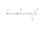
図1に示すように、カテーテルシステムは、アブレーション電極21を有する1つのアブレーションカテーテル10と、それぞれ第1ペーシング用電極41と第2ペーシング用電極45を有する2つのペーシング用カテーテル12,13とを有している。アブレーションカテーテル10には、アブレーション電極21に対する電力供給を制御する制御部14が接続されている。ペーシング用カテーテル12,13には、第1ペーシング用電極41と第2ペーシング用電極45に対する電力供給を制御する第2制御部16が接続されている。制御部14と第2制御部16には、第1ペーシング用電極41または第2ペーシング用電極45からの電気信号がアブレーション電極21に伝達するために必要な伝達時間を測定する測定部18が接続される。 As shown in FIG. 1, the catheter system includes one
制御部14は、第2制御部16に接続されている。制御部14は、第2制御部16から第1ペーシング用電極41及び第2ペーシング用電極45に対する電力供給のタイミングを受信する受信手段50を有している。受信手段50は、測定部18からの伝達時間の受信も行う。また、制御部14は、受信手段50で受信した第1ペーシング用電極41及び第2ペーシング用電極45に対する電力供給のタイミングと伝達時間の値とに基づいて、アブレーション電極21に対する電力供給のタイミングを調整する調整手段51を有している。 The
制御部14や第2制御部16は、CPUやメモリ等を有するコンピュータ等で構成することができる。また、測定部18は、制御部14や第2制御部16と独立して設けられているが、制御部14が測定部18の機能を有するようにしてもよい。 The
アブレーションカテーテル10について説明する。図2,3に示すように、アブレーションカテーテル10は、長尺管状のシャフト部20の先端部にアブレーション電極21とバルーン22とを有している。図2等では、簡略化のため、アブレーション電極21は2本のみ示されているが、アブレーション電極21は周方向により多数が設けられる。シャフト部20の基端部にはハブ23が設けられる。シャフト部20は、最外管30と、最外管30の内部に挿通される外管31と、外管31の内部に挿通されて先端部が突出する内管32とを有している。 The
最外管30の先端部には、アブレーション電極21の基端部を固定する基端部材36が設けられる。また、内管32の先端部には、アブレーション電極21の先端部を固定する先端部材35が設けられる。アブレーション電極21は、バルーン22の拡張に伴い径方向に拡張することができる。図4に示すように、アブレーション電極21は、バルーン22の拡張に伴い径方向に拡張することができる。 A
シャフト部20は、アブレーション電極21に電圧を印加するための接続線38を長さ方向に沿って有している。接続線38は、制御部14に接続されている。 The
外管31と内管32との間には拡張ルーメン33が形成される。また、内管32の内部にはガイドワイヤルーメン34が形成される。内管32は、外管31の先端よりもさらに先端側まで突出している。バルーン22は、基端側端部が外管31に固定され、先端側端部が内管32に固定されている。これにより、バルーン22の内部が拡張ルーメン33と連通している。拡張ルーメン33を介してバルーン22に拡張用流体を注入することで、バルーン22を拡張させることができる。拡張用流体は気体でも液体でもよく、例えばヘリウムガス、CO2ガス、O2ガス、笑気ガス等の気体や、生理食塩水、造影剤、およびその混合剤等の液体を用いることができる。An
最外管30と外管31及び内管32は、ある程度の可撓性を有する材料により形成されるのが好ましい。そのような材料としては、例えば、ポリエチレン、ポリプロピレン、ポリブテン、エチレン-プロピレン共重合体、エチレン-酢酸ビニル共重合体、アイオノマー、あるいはこれら二種以上の混合物等のポリオレフィンや、軟質ポリ塩化ビニル樹脂、ポリアミド、ポリアミドエラストマー、ポリエステル、ポリエステルエラストマー、ポリウレタン、ポリテトラフルオロエチレン等のフッ素樹脂、シリコーンゴム、ラテックスゴム等が挙げられる。 The
バルーン22は、薄膜状のバルーン膜によって形成されており、外管31や内管32と同様に、可撓性を有する材料によって形成される。また、アブレーション電極21を確実に押し広げる程度の強度も必要とされる。バルーン22の材質には、外管31や内管32について上で挙げたものを用いることができ、また、それ以外であってもよい。特に、血管(肺静脈)の根元の心腔表面をアブレーションする場合、血管内をアブレーションしてしまうとスパズム等によって血管が収縮してしまうことがある。そこで、血管内をアブレーションすることなく血管の根元の心腔表面をアブレーションするために、バルーン拡張径は約15mmから30mmに設定される。 The
図5に示すように、ペーシング用カテーテル12は、長尺なシャフト部40を有している。シャフト部40の基端部にはハブ42が、シャフト部40の先端部には第1ペーシング用電極41が、それぞれ設けられる。シャフト部40の材質は、アブレーションカテーテル10のシャフト部20と同様である。もう一つのペーシング用カテーテル13は、ペーシング用カテーテル12と同じ構成であって、シャフト部40の先端部には第2ペーシング用電極45を有する。 As shown in FIG. 5, pacing
次に、カテーテルシステムを用いた処置方法について説明する。始めに、セルジンガー法などによりイントロデューサー(図示しない)を経皮的に血管に穿刺する。次に、ガイドワイヤ(図示しない)を挿入後、ガイディングカテーテル(図示しない)を、イントロデューサーに挿入し、ガイドワイヤを先端側に突出させてから、ガイディングカテーテルの先端部をイントロデューサーの先端部開口から血管内へ挿入する。この後、ガイドワイヤを先行させつつ、ガイディングカテーテルを目的部位まで徐々に押し進める。術者は、右心房Ra側から左心房La側に向かって、所定の穿刺デバイスを貫通させることにより、心房中隔に貫通孔を形成する。穿刺デバイスは、例えば、先端が尖ったワイヤ等のデバイスを利用することができる。穿刺デバイスの送達は、ガイディングカテーテルを介して行うことができる。また、穿刺デバイスは、例えば、ガイディングカテーテルからガイドワイヤを抜去した後、ガイドワイヤに代えて心房中隔まで送達することができる。なお、心房中隔の貫通に使用される穿刺デバイスの具体的な構造、貫通孔を形成する際の具体的な手順等は特に限定されない。貫通孔を形成後、ダイレータを使って、貫通孔を押し広げ、貫通孔にガイディングカテーテルを通し、ガイドワイヤを使って目的部位(例えば、肺静脈付近)まで押し進める。ガイディングカテーテルは、ガイディングカテーテルの先端部が可動する機構を有してもよい。 Next, a treatment method using the catheter system will be described. First, an introducer (not shown) is percutaneously punctured into a blood vessel by the Seldinger method or the like. Next, after inserting a guide wire (not shown), a guiding catheter (not shown) is inserted into the introducer. It is inserted into the blood vessel through the orifice. After that, while leading the guide wire, the guiding catheter is gradually advanced to the target site. The operator forms a through hole in the interatrial septum by penetrating a predetermined puncture device from the right atrium Ra side toward the left atrium La side. The puncture device can utilize a device such as a wire with a sharp tip, for example. Delivery of the puncture device can be through a guiding catheter. Also, the puncture device can be delivered to the interatrial septum instead of the guidewire, for example, after the guidewire is removed from the guiding catheter. The specific structure of the puncture device used for penetrating the interatrial septum, the specific procedure for forming the through-hole, and the like are not particularly limited. After forming the through-hole, a dilator is used to expand the through-hole, a guiding catheter is passed through the through-hole, and a guide wire is used to advance it to the target site (for example, near the pulmonary veins). The guiding catheter may have a mechanism for moving the tip of the guiding catheter.
次に、ガイドワイヤルーメン34の先端部開口部に、ガイドワイヤの末端を挿入し、ハブ23からガイドワイヤを出す。次に、血管内に挿入されているガイディングカテーテル内に、アブレーションカテーテル10を先端部から挿入し、ガイドワイヤに沿わせてアブレーションカテーテル10を押し進める。 The distal end of the guidewire is then inserted into the distal opening of
アブレーションカテーテル10は、アブレーション電極21を有する先端部が左心房Laに送達される。ペーシング用カテーテル12は、第1ペーシング用電極41を有する先端部が右心房Raに送達される。ペーシング用カテーテル13は、第2ペーシング用電極45を有する先端部が右心室Rvに送達される。ペーシング用カテーテル12の第1ペーシング用電極41は、右心房Raのうち、高位右房(High Right Atrium)または冠静脈洞(Coronary Sinus)に配置されるのが望ましい。ただし、第1ペーシング用電極41は、それ以外の部位に配置されてもよい。第2ペーシング用電極45は、大腿静脈経由でアクセス容易な右心室Rvに配置されるが、左心室Lvに配置されてもよい。図6の例では、右心房Raに配置されたペーシング用電極41とアブレーション電極21との距離L1より、右心室Rvに配置されたペーシング用電極41とアブレーション電極21との距離L2の方が大きい。 The
各電極を所望の位置に配置したら、拡張ルーメン33を介して拡張用流体をバルーン22内に供給し、バルーン22を拡張させる。これにより、アブレーション電極21が径方向に拡張し、生体組織に密着する。 Once each electrode is in the desired position, an expansion fluid is supplied into
次に、測定部40は、第1ペーシング用電極41または第2ペーシング用電極45からの電気信号がアブレーション電極21に伝達される伝達時間Δtを測定する。第2制御部16は、アブレーション電極21からの距離が大きい右心室Rvに配置された第2ペーシング用電極45から電気信号を出力させる。制御部14は、アブレーション電極21に第2ペーシング用電極45からの電気信号を検出させることができる。測定部40は、第2制御部16により第2ペーシング用電極45から電気信号が出力されたタイミングと、制御部14によりアブレーション電極21で電気信号が検出されたタイミングとから、電気信号の伝達に要した伝達時間Δtを測定する。測定部18は、伝達時間の値を制御部14に送信し、制御部14は受信手段50で伝達時間の値Δtを受信する。 Next, the
次に、第2制御部16は、右心房Raに配置された第1ペーシング用電極41と、右心室Rvに配置された第2ペーシング用電極45から、一定の周期でペーシング信号を出力させる。図7において、V1は右心房Raに配置された第1ペーシング用電極41に印加される電圧を、V2は右心室Rvに配置された第2ペーシング用電極45に印加される電圧を、V3はアブレーション電極21に印加される電圧を、それぞれ表している。図7に示すように、両者は同時かつ同じ周期で印加される。第1ペーシング用電極41及び第2ペーシング用電極45からのペーシング信号は、通常心拍より早い周期、好ましくは通常心拍の1.3~1.5倍の周期で出力される。ペーシング信号は、電圧が3V~5Vの範囲に設定される。また、ペーシング信号のパルス幅は、1~300μsの範囲に設定される。 Next, the
心房の心筋は、ペーシング信号の出力からTaの時間に渡り、不応期の状態となる。心室の心筋は、ペーシング信号の出力からTvの時間に渡り、不応期の状態となる。一般的にTaは150ms前後、Tvは300ms前後である。図7において心房が不応期となるのは時間t1から時間t3まで、心室が不応期となるのは時間t1から時間t4までである。 The atrium myocardium is in a refractory period for a period of time Ta from the output of the pacing signal. The ventricular myocardium is in a refractory period for a period of time Tv from the output of the pacing signal. Generally, Ta is around 150 ms and Tv is around 300 ms. In FIG. 7, the atrium is in the refractory period from time t1 to time t3, and the ventricle is in the refractory period from time t1 to time t4.
制御部14の受信手段50は、第2制御部16から第1ペーシング用電極41及び第2ペーシング用電極45に対する電力供給のタイミングを受信し、このタイミングから伝達時間Δtの経過後であって、心房と心室がいずれも不応期となっている時間内に、アブレーション電極21に対して高電圧パルスを出力する。図7の例では、ペーシング信号の出力からΔtが経過した時間t2から、心房の不応期が終了する時間t3までの間である時間t5に、高電圧パルスが出力される。 The receiving means 50 of the
高電圧パルスは、断続的に出力されるペーシング信号の後のタイミングで複数回出力される。制御部14からは、まず、周方向に隣接する一対のアブレーション電極21,21に対して、高電圧パルスが出力される。これにより、周方向に隣接する一対のアブレーション電極21,21間に電流が流れる。次に、周方向に隣接する他の対のアブレーション電極21,21に対して、高電圧パルスが出力される。高電圧パルスの出力は、周方向に隣接する全ての対となるアブレーション電極21,21に対して、順次行われる。高電圧パルスの電圧の一例を以下に挙げる。制御部14が出力する電界強度は400~800V/cmであり、双極性の電圧波形を有する。そのパルス幅は100μsecであり、100μsec間隔で、一度に10~200バルスを出力する。電圧印加は、各電極間で0.5~2秒に1回のタイミングで繰り返される。これによって、肺静脈の入口の細胞を全周に渡って壊死させる。なお、ここでいう高電圧とは、電圧が印加される電極間で400V/cm以上の電界強度を達成できる電圧のことを指す。 The high voltage pulse is output multiple times at timing after the intermittent pacing signal. First, a high voltage pulse is output from the
高電圧パルスの出力が完了したら、バルーン22を収縮させる。これにより、アブレーション電極21も径方向に収縮する。その後、血管内に挿入された全ての器具を抜出し、処置を完了する。 After completing the output of the high voltage pulse, the
このように、カテーテルシステムは、電気信号が第1ペーシング用電極41または第2ペーシング用電極45からアブレーション電極21まで伝達するのに要する伝達時間Δtを測定し、ペーシング信号の出力から伝達時間Δtの経過後であって、ペーシング信号により心房と心室のいずれも不応期となっている時間内に、アブレーション電極21から高電圧パルスを出力する。これにより、カテーテルシステムは、心房と心室及びアブレーション電極21が配置された部位のいずれも確実に不応期に入った状態で、アブレーション電極21から高電圧パルスを出力できる。このため、カテーテルシステムは、高電圧パルスの出力が原因の術中不整脈発生を防止することができる。 Thus, the catheter system measures the travel time Δt required for an electrical signal to travel from
以上のように、本実施形態に係るカテーテルシステムは、アブレーション電極21を有するアブレーションカテーテル10と、アブレーション電極21に対する電力供給を制御する制御部14と、を有し、制御部14は、アブレーション電極21と異なる位置に配置されるペーシング用電極41,45に対する電力供給のタイミングと、ペーシング用電極41,45からアブレーション電極21の位置まで電気信号が伝達するために必要な伝達時間の値とを受信する受信手段50と、受信手段50で受信したペーシング用電極41,45に対する電力供給のタイミングと伝達時間の値に基づいて、アブレーション電極21に対する電力供給のタイミングを調整する調整手段51と、を有する。これにより、カテーテルシステムは、生体内に配置されたペーシング用電極41,45からアブレーション電極21の位置まで電気信号が伝達するために必要な伝達時間を考慮してアブレーション電極21に対する電極供給のタイミングを調整するので、アブレーション電極21が配置された位置の心筋が確実に不応期に入った状態で高電圧パルスを出力できる。これにより、カテーテルシステムは、高電圧パルスの出力が原因の術中不整脈発生を防止することができる。 As described above, the catheter system according to the present embodiment includes the
また、アブレーション電極21と異なる位置に配置されるペーシング用電極41,45を有するペーシング用カテーテル12,13と、ペーシング用電極41,45に対する電力供給を制御する第2制御部16と、を有するようにしてもよい。これにより、カテーテルシステムは、ペーシング用電極41,45からアブレーション電極21の位置まで電気信号が伝達するために必要な伝達時間を制御部14と第2制御部16とが有する情報から測定できる。 Further, the pacing
また、ペーシング用電極41,45からの電気信号がアブレーション電極21に伝達するために必要な伝達時間を測定する測定部18を有するようにしてもよい。これにより、カテーテルシステムは、伝達時間を容易に取得できる。 Further, a
また、アブレーション電極21は、ペーシング用電極41,45からの電気信号を検出し、測定部18は、電気信号がペーシング用電極41,45からアブレーション電極21に伝達されるまでの時間を測定するようにしてもよい。これにより、カテーテルシステムは、伝達時間測定のための電極を設ける必要がなく、手技を簡易化できる。 Also, the
また、調整手段51は、ペーシング用電極41,45に対する電力供給のタイミングから伝達時間の経過後であって、ペーシング用電極41,45からの電気信号により生体組織が不応期となる時間内に、アブレーション電極21に対して電力供給するようにタイミングを調整するようにしてもよい。これにより、カテーテルシステムは、ペーシング用電極41,45が配置された位置とアブレーション電極21が配置された位置の両方について、確実に不応期に入った状態で高電圧パルスを出力できる。 In addition, after the transmission time has passed from the timing of power supply to the
また、ペーシング用電極41,45は、心房に配置される第1ペーシング用電極41と心室に配置される第2ペーシング用電極45とを有し、調整手段51は、ペーシング用電極41,45に対する電力供給のタイミングから伝達時間の経過後であって、第1ペーシング用電極41からの電気信号により心房が不応期となる心房不応期時間と、第2ペーシング用電極45からの電気信号により心室が不応期となる心室不応期時間との重なった時間内に、アブレーション電極21に対して電力供給するようにタイミングを調整するようにしてもよい。これにより、カテーテルシステムは、心房と心室及びアブレーション電極21が配置された位置の全てについて、確実に不応期に入った状態で高電圧パルスを出力できる。 The
また、受信手段50が受信する伝達時間は、第1ペーシング用電極41と第2ペーシング用電極45のうち、アブレーション電極21から遠い方からアブレーション電極21まで電気信号が伝達するために必要な時間であるようにしてもよい。これにより、カテーテルシステムは、アブレーション電極21が配置された位置の心筋を確実に不応期の状態とした上で、高電圧パルスを出力できる。 The transmission time received by the receiving means 50 is the time required for an electrical signal to be transmitted from the
また、本実施形態に係る処置方法は、第1ペーシング用電極41を有するペーシング用カテーテル12を心房に、第2ペーシング用電極45を有するペーシング用カテーテル13を心室に、それぞれ挿入するステップと、
アブレーション電極21を有するアブレーションカテーテル10を所望の位置に挿入するステップと、
第1ペーシング用電極41または第2ペーシング用電極45から出力した電気信号を前記アブレーション電極21の位置で検出するまでの伝達時間を測定するステップと、
前記第1ペーシング用電極41と第2ペーシング用電極45からペーシング信号を出力するステップと、
前記ペーシング信号を出力したタイミングから前記伝達時間の経過後であって、前記ペーシング信号による心房の不応期終了前、かつ、前記ペーシング信号による心室の不応期終了前のタイミングで、前記アブレーション電極21から高電圧パルスを出力する。これにより、心房と心室及びアブレーション電極21が配置された位置のいずれも不応期の状態で高電圧パルスが出力されるので、高電圧パルスによる不整脈の誘発を防止できる。Further, the treatment method according to the present embodiment includes the step of inserting the pacing
inserting an
measuring the transmission time until the electrical signal output from the
outputting pacing signals from the
from the
また、前記第1ペーシング用電極41と第2ペーシング用電極45からの前記ペーシング信号の出力は同時であるようにしてもよい。これにより、アブレーション電極21からの距離が遠い方のペーシング電極からの伝達時間を測定するだけで、確実にアブレーション電極21の位置が不応期に入った状態で高電圧パルスを出力できる。 Also, the pacing signals may be output simultaneously from the
なお、本発明は、上述した実施形態のみに限定されるものではなく、本発明の技術的思想内において当業者により種々変更が可能である。上述の実施形態では、第2制御部16は第1ペーシング用電極41と第2ペーシング用電極45から同時にペーシング信号を出力させるが、ペーシング信号の出力のタイミングをずらしてもよい。 The present invention is not limited to the above-described embodiments, and various modifications can be made by those skilled in the art within the technical concept of the present invention. In the above-described embodiment, the
また、上述の実施形態では、アブレーションカテーテル10はバルーン22を有しているが、図8に示すようにバルーン22を有していなくてもよい。この場合、アブレーション電極21は、基端部が最外管30に、先端部が内管32に固定され、最外管30を内管32に対し長さ方向に移動させることで、アブレーション電極21を径方向に拡張、収縮させることができる。 Moreover, although the
またアブレーションカテーテルは、図9に示すような構成でもよい。図9(a)に示すように、アブレーションカテーテル60は、長尺管状のシャフト部61を有している。シャフト部61の内部には、長尺な電極支持体62が配置される。電極支持体62は、シャフト部61に対して長さ方向に移動できる。シャフト部61を生体100内に挿入する際には、電極支持体62はシャフト部61の内部に収納されている。 Alternatively, the ablation catheter may be configured as shown in FIG. As shown in FIG. 9( a ), the
図9(b)に示すように、電極支持体62は治療部位においてシャフト部61の先端側に露出される。電極支持体62は、長さ方向に沿って複数のアブレーション電極部63を有している。アブレーション電極部63は制御部14に接続され、電力供給を制御される。 As shown in FIG. 9B, the
10 アブレーションカテーテル
12 ペーシング用カテーテル
13 ペーシング用カテーテル
14 制御部
16 第2制御部
18 測定部
20 シャフト部
21 アブレーション電極
22 バルーン
23 ハブ
30 最外管
31 外管
32 内管
33 拡張ルーメン
34 ガイドワイヤルーメン
35 先端部材
36 基端部材
38 接続線
40 シャフト部
41 第1ペーシング用電極
42 ハブ
45 第2ペーシング用電極
50 受信手段
51 調整手段
Ra 右心房
Rv 右心室
La 左心房
Lv 左心室REFERENCE SIGNS
Claims (7)
Translated fromJapanese前記アブレーション電極に対する電力供給を制御する制御部と、を有し、
前記制御部は、前記アブレーション電極と異なる位置に配置されるペーシング用電極に対する電力供給のタイミングと、前記ペーシング用電極から前記アブレーション電極の位置まで電気信号が伝達するために必要な伝達時間の値とを受信する受信手段と、
前記受信手段で受信した前記ペーシング用電極に対する電力供給のタイミングと前記伝達時間の値に基づいて、前記アブレーション電極に対する電力供給のタイミングを調整する調整手段と、を有するカテーテルシステム。an ablation catheter having an ablation electrode;
a control unit that controls power supply to the ablation electrode;
The control unit controls the timing of power supply to a pacing electrode placed at a position different from the ablation electrode, and the value of the transmission time required for the electrical signal to be transmitted from the pacing electrode to the position of the ablation electrode. a receiving means for receiving
and adjusting means for adjusting the timing of power supply to the ablation electrode based on the timing of power supply to the pacing electrode and the value of the transmission time received by the receiving means.
前記ペーシング用電極に対する電力供給を制御する第2制御部と、を有する請求項1に記載のカテーテルシステム。a pacing catheter having a pacing electrode positioned at a position different from the ablation electrode;
2. The catheter system according to claim 1, further comprising a second controller that controls power supply to the pacing electrode.
前記測定部は、前記電気信号が前記ペーシング用電極から前記アブレーション電極に伝達されるまでの時間を測定する請求項3に記載のカテーテルシステム。the ablation electrode detects an electrical signal from the pacing electrode;
4. The catheter system according to claim 3, wherein the measurement unit measures the time it takes for the electrical signal to be transmitted from the pacing electrode to the ablation electrode.
前記調整手段は、前記ペーシング用電極に対する電力供給のタイミングから前記伝達時間の経過後であって、前記第1ペーシング用電極からの電気信号により心房が不応期となる心房不応期時間と、前記第2ペーシング用電極からの電気信号により心室が不応期となる心室不応期時間との重なった時間内に、前記アブレーション電極に対して電力供給するようにタイミングを調整する請求項5に記載のカテーテルシステム。the pacing electrode has a first pacing electrode placed in the atrium and a second pacing electrode placed in the ventricle;
The adjustment means comprises an atrial refractory period, which is after the transmission time has elapsed from the timing of power supply to the pacing electrode, during which the atrium is in a refractory period due to the electrical signal from the first pacing electrode; 6. The catheter system according to claim 5, wherein the timing is adjusted so that power is supplied to the ablation electrode within the time overlapping with the ventricular refractory period in which the ventricle becomes a refractory period due to electrical signals from the two pacing electrodes. .
Priority Applications (2)
| Application Number | Priority Date | Filing Date | Title |
|---|---|---|---|
| JP2020046033AJP2023056552A (en) | 2020-03-17 | 2020-03-17 | catheter system |
| PCT/JP2021/008618WO2021187154A1 (en) | 2020-03-17 | 2021-03-05 | Catheter system |
Applications Claiming Priority (1)
| Application Number | Priority Date | Filing Date | Title |
|---|---|---|---|
| JP2020046033AJP2023056552A (en) | 2020-03-17 | 2020-03-17 | catheter system |
Publications (1)
| Publication Number | Publication Date |
|---|---|
| JP2023056552Atrue JP2023056552A (en) | 2023-04-20 |
Family
ID=77772097
Family Applications (1)
| Application Number | Title | Priority Date | Filing Date |
|---|---|---|---|
| JP2020046033APendingJP2023056552A (en) | 2020-03-17 | 2020-03-17 | catheter system |
Country Status (2)
| Country | Link |
|---|---|
| JP (1) | JP2023056552A (en) |
| WO (1) | WO2021187154A1 (en) |
Families Citing this family (1)
| Publication number | Priority date | Publication date | Assignee | Title |
|---|---|---|---|---|
| US12076071B2 (en) | 2020-08-14 | 2024-09-03 | Kardium Inc. | Systems and methods for treating tissue with pulsed field ablation |
Family Cites Families (4)
| Publication number | Priority date | Publication date | Assignee | Title |
|---|---|---|---|---|
| US6564096B2 (en)* | 2001-02-28 | 2003-05-13 | Robert A. Mest | Method and system for treatment of tachycardia and fibrillation |
| EP1948296B2 (en)* | 2005-10-14 | 2017-10-11 | Pacesetter, Inc. | Leadless cardiac pacemaker and system |
| EP3399931B1 (en)* | 2016-01-05 | 2022-04-06 | Farapulse, Inc. | System for delivery of ablative energy to tissue |
| US9987081B1 (en)* | 2017-04-27 | 2018-06-05 | Iowa Approach, Inc. | Systems, devices, and methods for signal generation |
- 2020
- 2020-03-17JPJP2020046033Apatent/JP2023056552A/enactivePending
- 2021
- 2021-03-05WOPCT/JP2021/008618patent/WO2021187154A1/ennot_activeCeased
Also Published As
| Publication number | Publication date |
|---|---|
| WO2021187154A1 (en) | 2021-09-23 |
Similar Documents
| Publication | Publication Date | Title |
|---|---|---|
| US12070265B2 (en) | Electroporation system and method of preconditioning tissue for electroporation therapy | |
| CN110461262B (en) | Electroporation system and method of stimulating catheter | |
| JP6978286B2 (en) | Catheter system for ablating cardiac arrhythmias | |
| US5540679A (en) | Device and method for heating tissue in a patient's body | |
| JP7704888B2 (en) | Electroporation catheter, electroporation system, and method of assembling an electroporation catheter | |
| EP4134031B1 (en) | Systems for electroporation using asymmetric waveforms and waveforms with reduced burst duration | |
| KR20110040898A (en) | Compact Circular Mapping Catheter | |
| US20250009424A1 (en) | Electrode assembly including expandable isolation member | |
| JPWO2019181634A1 (en) | Medical device | |
| CN114305665A (en) | Split-capsule electrode catheter and ablation device comprising same | |
| US20250177040A1 (en) | Temperature controlled short duration ablation with resistive heating | |
| JP2023056552A (en) | catheter system | |
| CN112716599B (en) | Electrode assembly including an expandable isolation member | |
| JP2021142209A (en) | Catheter system | |
| JP7428816B2 (en) | Electrode assembly including expandable isolation member | |
| JP2022120368A (en) | catheter | |
| JP2021142210A (en) | Catheter system and voltage application method for catheter system | |
| RU2774573C1 (en) | Protocol of careful irreversible electroporation (ire) for preventing the formation of bubbles | |
| US20230310053A1 (en) | Systems and methods for performing a denervation procedure and determining the efficacy thereof | |
| EP4493090A1 (en) | Systems and methods for performing a denervation procedure and determining the efficacy thereof |