JP2023053112A - occlusion device - Google Patents
occlusion deviceDownload PDFInfo
- Publication number
- JP2023053112A JP2023053112AJP2023018404AJP2023018404AJP2023053112AJP 2023053112 AJP2023053112 AJP 2023053112AJP 2023018404 AJP2023018404 AJP 2023018404AJP 2023018404 AJP2023018404 AJP 2023018404AJP 2023053112 AJP2023053112 AJP 2023053112A
- Authority
- JP
- Japan
- Prior art keywords
- mesh
- axial
- aneurysm
- sections
- section
- Prior art date
- Legal status (The legal status is an assumption and is not a legal conclusion. Google has not performed a legal analysis and makes no representation as to the accuracy of the status listed.)
- Granted
Links
Images


Classifications
- A—HUMAN NECESSITIES
- A61—MEDICAL OR VETERINARY SCIENCE; HYGIENE
- A61B—DIAGNOSIS; SURGERY; IDENTIFICATION
- A61B17/00—Surgical instruments, devices or methods
- A61B17/12—Surgical instruments, devices or methods for ligaturing or otherwise compressing tubular parts of the body, e.g. blood vessels or umbilical cord
- A61B17/12022—Occluding by internal devices, e.g. balloons or releasable wires
- A61B17/12131—Occluding by internal devices, e.g. balloons or releasable wires characterised by the type of occluding device
- A61B17/12168—Occluding by internal devices, e.g. balloons or releasable wires characterised by the type of occluding device having a mesh structure
- A61B17/12172—Occluding by internal devices, e.g. balloons or releasable wires characterised by the type of occluding device having a mesh structure having a pre-set deployed three-dimensional shape
- A—HUMAN NECESSITIES
- A61—MEDICAL OR VETERINARY SCIENCE; HYGIENE
- A61B—DIAGNOSIS; SURGERY; IDENTIFICATION
- A61B17/00—Surgical instruments, devices or methods
- A61B17/0057—Implements for plugging an opening in the wall of a hollow or tubular organ, e.g. for sealing a vessel puncture or closing a cardiac septal defect
- A—HUMAN NECESSITIES
- A61—MEDICAL OR VETERINARY SCIENCE; HYGIENE
- A61B—DIAGNOSIS; SURGERY; IDENTIFICATION
- A61B17/00—Surgical instruments, devices or methods
- A61B17/12—Surgical instruments, devices or methods for ligaturing or otherwise compressing tubular parts of the body, e.g. blood vessels or umbilical cord
- A61B17/12022—Occluding by internal devices, e.g. balloons or releasable wires
- A61B17/12099—Occluding by internal devices, e.g. balloons or releasable wires characterised by the location of the occluder
- A61B17/12109—Occluding by internal devices, e.g. balloons or releasable wires characterised by the location of the occluder in a blood vessel
- A61B17/12113—Occluding by internal devices, e.g. balloons or releasable wires characterised by the location of the occluder in a blood vessel within an aneurysm
- A—HUMAN NECESSITIES
- A61—MEDICAL OR VETERINARY SCIENCE; HYGIENE
- A61B—DIAGNOSIS; SURGERY; IDENTIFICATION
- A61B17/00—Surgical instruments, devices or methods
- A61B17/12—Surgical instruments, devices or methods for ligaturing or otherwise compressing tubular parts of the body, e.g. blood vessels or umbilical cord
- A61B17/12022—Occluding by internal devices, e.g. balloons or releasable wires
- A61B17/12131—Occluding by internal devices, e.g. balloons or releasable wires characterised by the type of occluding device
- A61B17/12163—Occluding by internal devices, e.g. balloons or releasable wires characterised by the type of occluding device having a string of elements connected to each other
- A—HUMAN NECESSITIES
- A61—MEDICAL OR VETERINARY SCIENCE; HYGIENE
- A61B—DIAGNOSIS; SURGERY; IDENTIFICATION
- A61B17/00—Surgical instruments, devices or methods
- A61B17/0057—Implements for plugging an opening in the wall of a hollow or tubular organ, e.g. for sealing a vessel puncture or closing a cardiac septal defect
- A61B2017/00575—Implements for plugging an opening in the wall of a hollow or tubular organ, e.g. for sealing a vessel puncture or closing a cardiac septal defect for closure at remote site, e.g. closing atrial septum defects
- A61B2017/00632—Occluding a cavity, i.e. closing a blind opening
- A—HUMAN NECESSITIES
- A61—MEDICAL OR VETERINARY SCIENCE; HYGIENE
- A61B—DIAGNOSIS; SURGERY; IDENTIFICATION
- A61B17/00—Surgical instruments, devices or methods
- A61B2017/00831—Material properties
- A61B2017/00862—Material properties elastic or resilient
- A—HUMAN NECESSITIES
- A61—MEDICAL OR VETERINARY SCIENCE; HYGIENE
- A61B—DIAGNOSIS; SURGERY; IDENTIFICATION
- A61B17/00—Surgical instruments, devices or methods
- A61B2017/00831—Material properties
- A61B2017/00867—Material properties shape memory effect
- A—HUMAN NECESSITIES
- A61—MEDICAL OR VETERINARY SCIENCE; HYGIENE
- A61B—DIAGNOSIS; SURGERY; IDENTIFICATION
- A61B17/00—Surgical instruments, devices or methods
- A61B17/12—Surgical instruments, devices or methods for ligaturing or otherwise compressing tubular parts of the body, e.g. blood vessels or umbilical cord
- A61B17/12022—Occluding by internal devices, e.g. balloons or releasable wires
- A61B2017/1205—Introduction devices
- A61B2017/12054—Details concerning the detachment of the occluding device from the introduction device
- A61B2017/12063—Details concerning the detachment of the occluding device from the introduction device electrolytically detachable
- A—HUMAN NECESSITIES
- A61—MEDICAL OR VETERINARY SCIENCE; HYGIENE
- A61B—DIAGNOSIS; SURGERY; IDENTIFICATION
- A61B90/00—Instruments, implements or accessories specially adapted for surgery or diagnosis and not covered by any of the groups A61B1/00 - A61B50/00, e.g. for luxation treatment or for protecting wound edges
- A61B90/39—Markers, e.g. radio-opaque or breast lesions markers
- A61B2090/3966—Radiopaque markers visible in an X-ray image
Landscapes
- Health & Medical Sciences (AREA)
- Surgery (AREA)
- Life Sciences & Earth Sciences (AREA)
- Medical Informatics (AREA)
- Animal Behavior & Ethology (AREA)
- Engineering & Computer Science (AREA)
- Biomedical Technology (AREA)
- Heart & Thoracic Surgery (AREA)
- Veterinary Medicine (AREA)
- Molecular Biology (AREA)
- Nuclear Medicine, Radiotherapy & Molecular Imaging (AREA)
- General Health & Medical Sciences (AREA)
- Public Health (AREA)
- Reproductive Health (AREA)
- Vascular Medicine (AREA)
- Neurosurgery (AREA)
- Cardiology (AREA)
- Surgical Instruments (AREA)
Abstract
Translated fromJapaneseDescription
Translated fromJapanese関連出願
本明細書中及び上記の参照出願で引用したすべての文書及び参照文献は参照により本明細書中に援用される。RELATED APPLICATIONS All documents and references cited herein and in the above referenced applications are hereby incorporated by reference.
本明細書中に開示される閉塞デバイスは、全般的に、閉塞デバイス及び/又は閉塞デバイスシステム及び/又は植え込み型閉塞デバイスの分野、並びに血管の閉塞並びに/又は動脈瘤の処置及び/又は改善のための、並びに/又は例えば、末梢動脈若しくは静脈の病状及び/若しくは処置のために血管閉塞を必要とする任意の関連の病状の処置及び/又は改善における末梢血管塞栓術(当技術分野で周知のプロセスであり、特定の血管部位の遠位側における血流停止を伴うことが知られている)のための、閉塞デバイス及び/又は閉塞デバイスシステム及び/又は植え込み型閉塞デバイスの使用に関する。 The occlusive devices disclosed herein generally refer to the field of occlusive devices and/or occlusive device systems and/or implantable occlusive devices and the treatment and/or amelioration of vascular occlusion and/or aneurysms. and/or in the treatment and/or amelioration of any related medical condition requiring vascular occlusion, e.g., peripheral arterial or venous conditions and/or treatment (well known in the art The present invention relates to the use of occlusive devices and/or occlusive device systems and/or implantable occlusive devices for a process known to involve cessation of blood flow distal to a particular vascular site.
動脈瘤の処置及び/又は改善のための、改良された閉塞デバイス及び/又はシステムの開発に対する大きな需要がある。この見解は、現在の動脈瘤末梢血管塞栓術処置分野における現在の閉塞デバイス及び/又はシステムの豊富さ及び広範さにより支持されている。しかしながら、特に神経血管系動脈瘤の動脈瘤処置及び/又は改善を、血行静止の導入のためにより大きな血流阻止及び区画化を達成するように設計された並びに/又はより大きな及び/若しくはより不規則な形状の動脈瘤を閉塞するように設計された留置可能な材料を含む閉塞デバイスにより提供することに対する未対処の需要が依然として存在する。 There is a significant need to develop improved occlusion devices and/or systems for treating and/or ameliorating aneurysms. This view is supported by the abundance and breadth of current occlusion devices and/or systems in the current field of peripheral aneurysm embolization procedures. However, aneurysm treatment and/or amelioration, particularly of neurovascular aneurysms, designed to achieve greater blood flow blockage and compartmentalization for the introduction of hemostasis and/or larger and/or less bulky aneurysms. There remains an unmet need to provide occlusion devices comprising deployable materials designed to occlude regular shaped aneurysms.
動脈瘤は動脈の拡張部が血圧により薄く伸ばされると形成することは周知である。動脈の脆弱化した部分は、漏出及び/又は破裂の危険性がある隆起又は球状領域を形成する。神経血管系動脈瘤が破裂すると、脳を取り囲む間隙であるくも膜下腔への出血を引き起こし、くも膜下出血の原因となる。破裂神経血管系動脈瘤によるくも膜下出血は、出血性脳卒中、脳損傷及び死に至る可能性がある。神経血管系動脈瘤を持つ全患者の約25パーセントがくも膜下出血に罹患する。神経血管系動脈瘤は人口の2~5パーセントに発症し、より一般的には、男性よりも女性に発症する。現在米国に在住の1800万人もが一生のうちに神経血管系動脈瘤を発症すると推定されている。毎年、米国内のくも膜下出血の発症数は30,000人を超えている。これら患者の10~15パーセントが病院に到着する前に死亡しており、50パーセント超が破裂後最初の30日以内に死亡している。助かった人のうち、約半数が何らかの永久的な神経障害を患う。 It is well known that an aneurysm forms when an arterial dilation is thinned out by blood pressure. A weakened portion of an artery creates a bulge or bulbous area at risk of leakage and/or rupture. Rupture of a neurovascular aneurysm causes bleeding into the subarachnoid space, the space surrounding the brain, causing subarachnoid hemorrhage. Subarachnoid hemorrhage from ruptured neurovascular aneurysms can lead to hemorrhagic stroke, brain damage and death. Approximately 25 percent of all patients with neurovascular aneurysms suffer from subarachnoid hemorrhage. Neurovascular aneurysms affect 2-5 percent of the population and are more common in women than men. It is estimated that as many as 18 million people currently living in the United States will develop a neurovascular aneurysm in their lifetime. There are over 30,000 cases of subarachnoid hemorrhage in the United States each year. Ten to fifteen percent of these patients die before reaching the hospital, and more than fifty percent die within the first 30 days after rupture. About half of those who survive suffer some form of permanent neurological damage.
喫煙、高血圧、外傷性頭部外傷、アルコール乱用、ホルモン不妊法の使用、脳動脈瘤の家族歴、並びにエーラースダンロス症候群(EDS)、多発性嚢胞腎疾患及びマルファン症候群などの他の遺伝性疾患が、神経血管系動脈瘤の一因となっている可能性がある。 Smoking, hypertension, traumatic head injury, alcohol abuse, use of hormonal sterilization methods, family history of cerebral aneurysms, and other hereditary conditions such as Ehlers-Danlos syndrome (EDS), polycystic kidney disease and Marfan syndrome. Disease may contribute to neurovascular aneurysms.
大部分の未破裂動脈瘤は無症候性である。未破裂動脈瘤を持つ人の一部は、以下の症状、即ち、周辺視障害、思考又は処理障害、会話困難、知覚障害、態度の急な変化、平衡及び協調の喪失、集中力低下、短期記憶困難及び疲労、のいくつか又はすべてを経験する。破裂神経血管系動脈瘤の症状としては、悪心及び嘔吐、頚部硬直又は頚部痛、霧視又は複視、眼の上及び奥の痛み、瞳孔散大、光過敏、並びに感覚の喪失が挙げられる。時として「人生最悪の頭痛」と表現する患者は、破裂神経血管系動脈瘤の症状の1つを経験している。 Most unruptured aneurysms are asymptomatic. Some people with unruptured aneurysms have the following symptoms: impaired peripheral vision, impaired thinking or processing, difficulty speaking, impaired perception, sudden changes in attitude, loss of balance and coordination, poor concentration, short-term Experiencing some or all of memory difficulties and fatigue. Symptoms of a ruptured neurovascular aneurysm include nausea and vomiting, neck stiffness or pain, blurred or double vision, pain above and behind the eye, dilated pupils, sensitivity to light, and loss of sensation. Patients, who sometimes describe themselves as "the worst headache of their lives," experience one of the symptoms of a ruptured neurovascular aneurysm.
ほとんどの動脈瘤は破裂が起こるまで発見されないままである。しかしながら、動脈瘤
は、日常的な健康診断又は他の健康問題の診断手順の最中に発見される場合がある。破裂脳動脈瘤の診断は、一般に、くも膜下出血の徴候をCTスキャン(コンピュータ断層撮影法)で発見することにより行われる。CTスキャンが陰性ではあるものの破裂動脈瘤がなお疑われる場合、脳及び脊髄を取り囲む脳脊髄液(CSF)中の血液を検出するために、腰椎穿刺が実施される。Most aneurysms remain undiscovered until rupture occurs. However, an aneurysm may be discovered during a routine physical examination or diagnostic procedure for other health problems. Diagnosis of a ruptured brain aneurysm is generally made by finding signs of subarachnoid hemorrhage on a CT scan (computed tomography). If the CT scan is negative but a ruptured aneurysm is still suspected, a lumbar puncture is performed to detect blood in the cerebrospinal fluid (CSF) surrounding the brain and spinal cord.
神経放射線科医は、動脈瘤の正確な位置、大きさ及び形状を特定するために、脳血管造影法又は断層血管造影法のいずれかを使用する。従来の方法である脳血管造影法には、(通常、下肢の)動脈にカテーテルを導入し、それを体の血管内において、動脈瘤に関与する動脈まで進めることを含む。造影剤と呼ばれる特殊な色素を患者の動脈内に注入し、その分布をX線投影で示す。この方法では、重なった構造又は攣縮が原因で一部の動脈瘤を検出しない場合がある。 Neuroradiologists use either cerebral angiography or cross-sectional angiography to determine the exact location, size and shape of the aneurysm. A traditional method, cerebral angiography, involves introducing a catheter into an artery (usually in the leg) and advancing it through the body's vessels to the artery involved in the aneurysm. A special dye called a contrast agent is injected into the patient's arteries and its distribution is shown in an x-ray projection. This method may not detect some aneurysms due to overlapping structures or spasm.
コンピュータ断層血管造影法(CTA)は、従来の方法の代替となるものであり、動脈カテーテル法を要することなく実施され得る。この検査では、通常のCTスキャンに静脈内への造影剤色素の注入を組み合わせる。色素が静脈内に注入されると色素は脳動脈へと移動し、CTスキャンを用いて像が形成される。これら像は、血液が脳動脈にどのように流れ込むかを正確に示す。新たな診断様式は、伝統的及び従来的両方の診断的研究を低侵襲性の画像化により補完するものと見込まれ、動脈瘤の病状に対するより正確な3次元の解剖学的情報を提供する可能性がある。より良好な画像化は、向上した低侵襲治療の発展との組み合わせにおいて、医師がますます、より多くの無症状の動脈瘤を、問題が生じる前に検出し、処置することが可能になる。 Computed tomography angiography (CTA) is an alternative to conventional methods and can be performed without the need for arterial catheterization. This test combines a routine CT scan with an intravenous contrast dye injection. When the dye is injected intravenously, it travels to the brain arteries and is imaged using a CT scan. These images show exactly how blood flows into the cerebral arteries. Emerging diagnostic modalities are expected to complement both traditional and conventional diagnostic studies with minimally invasive imaging, potentially providing more accurate three-dimensional anatomical information for aneurysm pathology. have a nature. Better imaging, in combination with the development of improved minimally invasive treatments, will enable physicians to detect and treat more and more asymptomatic aneurysms before they become problems.
動脈瘤を処置するいくつかの方法が試みられてきており、成功の程度は様々であった。例えば、開頭術は、動脈瘤が血管外で特定及び処置される手技である。この種の手技は大きな欠点を有する。例えば、動脈瘤に到達するために外科医が様々な組織を切断しなければならないことによって、患者は動脈瘤の領域に多大な外傷を被る。脳動脈瘤を血管外で処置するには、例えば、外科医は、一般に、患者の頭蓋の一部を取り外さなければならず、また、動脈瘤に到達するために脳組織を損傷しなければならない。このため、手術のせいで患者がてんかんを発症する可能性がある。 Several methods of treating aneurysms have been attempted with varying degrees of success. For example, a craniotomy is a procedure in which an aneurysm is identified and treated extravascularly. This type of procedure has major drawbacks. For example, the patient suffers a great deal of trauma in the area of the aneurysm due to the surgeon having to cut various tissues to reach the aneurysm. To treat a brain aneurysm extravascularly, for example, a surgeon generally must remove a portion of the patient's skull and damage brain tissue to reach the aneurysm. Therefore, the patient may develop epilepsy as a result of the surgery.
動脈瘤の処置に使用される他の手法は血管内で実施される。このような手法には、一般に、動脈瘤の嚢内に塊を形成しようとすることを含む。一般に、動脈瘤へのアクセスにはマイクロカテーテルが使用される。マイクロカテーテルの遠位先端部は動脈瘤の嚢内に配置され、マイクロカテーテルを用いて、塞栓材料を動脈瘤の嚢内に注入する。塞栓材料には、例えば、離脱式コイル、又は液体ポリマーなどの塞栓剤を含む。これら種類の塞栓材料の注入には欠点があり、そのほとんどは、動脈瘤から親動脈への塞栓材料の逸脱に関連するものである。これは、親動脈の永久的且つ不可逆的な閉塞の原因となり得る。 Other procedures used to treat aneurysms are performed intravascularly. Such procedures generally involve attempting to form a mass within the aneurysm sac. Microcatheters are commonly used to access aneurysms. The distal tip of the microcatheter is placed within the aneurysm sac and the microcatheter is used to inject embolic material into the aneurysm sac. Embolic materials include, for example, detachable coils or embolic agents such as liquid polymers. Injection of these types of embolic material has drawbacks, most of which relate to migration of the embolic material from the aneurysm into the parent artery. This can cause permanent and irreversible occlusion of the parent artery.
例えば、十分に画定された頚部領域を有しない動脈瘤を、離脱式コイルを用いて閉塞する場合、離脱式コイルは動脈瘤の嚢から親動脈へと逸脱する可能性がある。更に、離脱式コイルが留置されたときに動脈瘤の嚢がどれほど充満しているかを正確に計測することは困難な場合がある。このため、動脈瘤に過剰充填するリスクがあり、この場合もまた、離脱式コイルは親動脈内に流出する。 For example, if a detachable coil is used to occlude an aneurysm that does not have a well-defined neck region, the detachable coil may escape from the aneurysm sac into the parent artery. Furthermore, it can be difficult to accurately gauge how full the aneurysm sac is when the detachable coil is deployed. Thus, there is a risk of overfilling the aneurysm and again the detachable coil spills into the parent artery.
離脱式コイルの別の欠点には、経時的なコイルの圧密化を含む。動脈瘤の充填後、コイルの間に空間が残る。循環による継続的な血行力学的力がコイルの塊を圧密化するように作用し、動脈瘤頚部に空洞が生じる。このため、動脈瘤が再開通する可能性がある。 Another drawback of detachable coils includes compaction of the coil over time. After filling the aneurysm, a space remains between the coils. Continued hemodynamic forces due to circulation act to compact the coil mass, creating a cavity at the aneurysm neck. Therefore, the aneurysm may recanalize.
塞栓剤の逸脱も問題である。例えば、液体ポリマーが動脈瘤の嚢内に注入される場合、
系の血行力学により、液体ポリマーは動脈瘤の嚢から逸脱する可能性がある。これもまた、親血管の不可逆的な閉塞につながる可能性がある。Embolic agent escape is also a problem. For example, if a liquid polymer is injected into the aneurysm sac,
The hemodynamics of the system may allow the liquid polymer to escape from the aneurysm sac. This too can lead to irreversible occlusion of the parent vessel.
塞栓材料の親血管への逸脱に関連する欠点に対処するための手法が試みられてきた。このような手法は、限定されるものではないが、一時的血流停止及び親血管閉塞であり、一般に、動脈瘤の嚢内に血栓の塊が形成されるまで親血管への血流が生じないように、親血管を動脈瘤の近位側で一時的に閉塞することを含む。理論では、これは、塞栓材料が動脈瘤嚢から逸脱する傾向を低下させる。しかしながら、血栓の塊は血液の通常の溶解により溶け得ることが判明している。また、ある場合においては、患者のリスク/利益の観点から、親血管を一時的であっても閉塞することは非常に望ましくない。このため、この手法は、治療オプションとして利用できない場合がある。加えて、現在では、親血管を閉塞してもすべての塞栓材料の親血管への逸脱を防ぎ得ないことは知られている。 Approaches have been attempted to address the drawbacks associated with migration of embolic material into the parent vessel. Such procedures include, but are not limited to, temporary blood flow arrest and parent vessel occlusion, which generally does not allow blood flow to the parent vessel until a thrombotic mass forms within the aneurysm sac. As such, it involves temporarily occluding the parent vessel proximal to the aneurysm. In theory, this reduces the tendency of embolic material to escape from the aneurysm sac. However, it has been found that thrombotic clots can be lysed by normal dissolution of blood. Also, in some cases, even temporary occlusion of the parent vessel is highly undesirable from a patient risk/benefit standpoint. Therefore, this approach may not be available as a treatment option. In addition, it is now known that occlusion of the parent vessel does not prevent all embolic material from migrating into the parent vessel.
動脈瘤を処置するための別の血管内手法には、マイクロカテーテルを用いて離脱式バルーンを動脈瘤の嚢内に挿入することを含む。離脱式バルーンは、その後、生理食塩水及び/又は造影剤流体を用いて拡張させる。バルーンは、その後、マイクロカテーテルから離脱されて動脈瘤の嚢内に残され、動脈瘤の嚢を充填することが試みられる。しかしながら、離脱式バルーンにも欠点があることから、この手法は、コイルの留置という現在の手法又は他の種類の閉塞デバイスにほとんど取って代わられている。例えば、離脱式バルーンは、拡張させたときに、一般に、動脈瘤嚢の内部構成に適合しない。その代わり、離脱式バルーンでは、動脈瘤嚢を離脱式バルーンの外部表面に適合させることが必要である。このため、離脱式バルーンが動脈瘤の嚢を破裂させるリスクが高まる。更に、離脱式バルーンが破裂し、動脈瘤から逸脱するおそれがある。 Another endovascular approach to treating an aneurysm involves inserting a detachable balloon into the aneurysm sac using a microcatheter. The detachable balloon is then inflated with saline and/or contrast fluid. The balloon is then withdrawn from the microcatheter and left in the aneurysm sac to attempt to fill the aneurysm sac. However, detachable balloons also have drawbacks, and this approach has largely been superseded by the current approach of coil placement or other types of occlusive devices. For example, detachable balloons generally do not conform to the internal configuration of the aneurysm sac when expanded. Instead, a detachable balloon requires the aneurysm sac to conform to the exterior surface of the detachable balloon. This increases the risk that the detachable balloon will rupture the aneurysm sac. Additionally, the detachable balloon can rupture and protrude from the aneurysm.
動脈瘤を処置するための別の血管内手法には、2つの拡張可能なローブ及びウエスト、又は拡張可能な本体部分、首部及び基部を有する閉塞デバイスを含む。 Other endovascular approaches to treat aneurysms include occlusion devices having two expandable lobes and a waist, or an expandable body portion, neck and base.
動脈瘤を処置するための更に別の血管内手法には、動脈瘤の嚢内の空間内を充填する及び/又は径方向に拡張するように設計された本体部分を有する嚢内植え込み用の閉塞デバイスを含む。 Yet another endovascular approach to treating an aneurysm includes an occlusive device for intracapsular implantation having a body portion designed to fill and/or radially expand the intracapsular space of the aneurysm. include.
更に別の血管内手法は、参照によって全体が本明細書に組み込まれる共有の係属中の出願である米国特許出願第14/699,188号明細書に開示されている。 Yet another intravascular approach is disclosed in commonly-owned, pending US patent application Ser. No. 14/699,188, which is hereby incorporated by reference in its entirety.
現在の閉塞デバイスの多くは、例えば、広及び狭頸動脈瘤、側壁型及び分岐型動脈瘤を含む、大きな動脈瘤又は不規則な形状及び大きさの動脈瘤の処置のためには設計されていない。現在の閉塞デバイスの多くは、編み込まれた又は織られたメッシュ設計で構成されており、このような設計は、大きく且つ不規則な形状の動脈瘤用に再構成した場合、一般に、使用する材料が多すぎる。これにより、送出カテーテル又は他の送出ルーメンの壁に過剰な摩擦をかけることなく送出及び留置されるほど十分に小さい、制限された薄型の送出構成へとつぶれることが困難になる。これらデバイスの単に嵩高さによって、デバイスは頭蓋内送出にとって不便又は不適切となる。 Many current occlusion devices are not designed for the treatment of large or irregularly shaped and sized aneurysms, including, for example, wide and narrow carotid aneurysms, lateral and bifurcated aneurysms. do not have. Many of the current occlusive devices are constructed with braided or woven mesh designs, which, when reconfigured for large and irregularly shaped aneurysms, are generally less too many. This makes it difficult to collapse into a limited low profile delivery configuration that is small enough to be delivered and deployed without applying excessive friction to the walls of the delivery catheter or other delivery lumen. The mere bulkiness of these devices makes them inconvenient or unsuitable for intracranial delivery.
したがって、本明細書中に開示される閉塞デバイスは、超圧密化可能な連続的なメッシュベースの完全に回収可能な留置可能材料の使用によって、特に大きく且つ不規則なサイズの神経血管動脈瘤のための、動脈瘤及び/又は体腔処置及び/又は改善を提供することから、本明細書中に開示される閉塞デバイスは、血管閉塞デバイスの分野における革新的改良及びいくつかの利点を提供する。本明細書中に開示される閉塞デバイスは、メッシュベースの留置可能な連続的構造体を含む。この連続的構造体は、端部と端部とを繋げて構成され、連続的なメッシュ構造体のいずれの端部にも挟持点を画定する圧縮可能な軸方向
メッシュキャリッジを有する。この新規な設計は、動脈瘤又は体腔内のより大きな血流阻止及び区画化を実現し、特により大きく且つより不規則な形状の動脈瘤を閉塞するための血行静止の増大をもたらす。Thus, the occlusive device disclosed herein provides a method for treating neurovascular aneurysms, particularly large and irregularly sized aneurysms, through the use of an ultra-consolidable, continuous mesh-based, fully retrievable, indwellable material. The occlusion devices disclosed herein provide a revolutionary improvement and several advantages in the field of vascular occlusion devices, since they provide aneurysm and/or body cavity treatment and/or improvement for. The occlusive devices disclosed herein comprise mesh-based deployable continuous structures. The continuous structure has compressible axial mesh carriages configured end-to-end and defining pinch points at either end of the continuous mesh structure. This novel design provides greater blood flow blockage and compartmentalization within an aneurysm or body lumen, providing increased stasis, especially for occluding larger and more irregularly shaped aneurysms.
本明細書中及び参照した特許文献に引用されたすべての文書及び参照文献は参照により本明細書中に援用される。 All documents and references cited in this specification and in the referenced patent documents are hereby incorporated by reference.
本発明者は、動脈瘤嚢内に留置し、血流阻止の生成及び最終的な血行静止によって動脈瘤処置及び/又は改善をもたらすための動脈瘤内閉塞デバイスを設計した。閉塞デバイスは、一連の圧縮可能なメッシュキャリッジを一意的に含む。一連の圧縮可能なメッシュキャリッジは、各端部に、キャリッジを画定する別個の挟持点を有し、動脈瘤内部に、血流阻止、血栓形成及び/又は細胞成長のための枠組みのための連続的な3次元メッシュ網を提供する。このような植え込み型閉塞デバイスはまた、血管閉塞の処置及び/又は末梢血管塞栓術のために使用される。 The inventors have designed an aneurysmal occlusion device for placement within the aneurysm sac to effect aneurysm treatment and/or amelioration by producing flow arrest and eventual stasis. Occlusive devices uniquely include a series of compressible mesh carriages. A series of compressible mesh carriages have, at each end, separate pinch points defining the carriages, and within the aneurysm, a continuous mesh for framing for blood flow arrest, thrombus formation and/or cell growth. provides a realistic three-dimensional mesh network. Such implantable occlusive devices are also used for treatment of vascular occlusions and/or peripheral embolization.
本明細書中に開示されるのは、体腔又は動脈瘤内に植え込むための閉塞デバイスである。閉塞デバイスは、端部と端部とを繋げて構成された軸方向メッシュキャリッジを含む連続的な圧縮可能なメッシュ構造体を含み、各キャリッジの各端部は、連続的なメッシュ構造体の挟持点である。 Disclosed herein are occlusive devices for implantation within a body cavity or aneurysm. The occlusion device includes a continuous compressible mesh structure including axial mesh carriages configured end-to-end, each end of each carriage sandwiching the continuous mesh structure. It is a point.
一実施形態では、マーカーが連続的なメッシュ構造体の少なくとも1つの挟持点を囲み覆っている。更なる実施形態では、マーカーは放射線不透過性である。 In one embodiment, markers surround at least one pinch point of the continuous mesh structure. In a further embodiment, the marker is radiopaque.
別の実施形態では、連続的なメッシュ構造体の少なくとも1つのメッシュキャリッジは、1つの内部同軸メッシュキャリッジ又は複数の内部同軸メッシュキャリッジを含む。更なる実施形態では、1つの内部同軸メッシュキャリッジ又は複数のキャリッジは、その外部メッシュキャリッジとは異なる材料である。更なる実施形態では、複数の内部同軸メッシュキャリッジは、2つ又は3つの内部同軸メッシュキャリッジである。別の更なる実施形態では、1つの内部同軸メッシュキャリッジ又は複数のキャリッジは、その外部メッシュキャリッジとは異なるメッシュ密度である。 In another embodiment, the at least one mesh carriage of the continuous mesh structure comprises an internal coaxial mesh carriage or multiple internal coaxial mesh carriages. In a further embodiment, the inner coaxial mesh carriage or carriages is of a different material than the outer mesh carriage. In further embodiments, the plurality of internal coaxial mesh carriages is two or three internal coaxial mesh carriages. In another further embodiment, the inner coaxial mesh carriage or carriages is of a different mesh density than the outer mesh carriage.
別の実施形態では、連続的なメッシュ構造体は留置形状に拡張し、体腔又は動脈瘤を充填する。 In another embodiment, the continuous mesh structure expands to an indwelling configuration to fill a body cavity or aneurysm.
別の実施形態では、軸方向メッシュキャリッジの数(n)は、2、3、4又は5つの軸方向メッシュキャリッジである。 In another embodiment, the number (n) of axial mesh carriages is 2, 3, 4 or 5 axial mesh carriages.
また、本明細書中に開示されるのは、体腔又は動脈瘤の処置及び/又は改善用のキットである。キットは、端部と端部とを繋げて構成された軸方向メッシュキャリッジを含む連続的な圧縮可能なメッシュ構造体を含む、体腔又は動脈瘤内に植え込むための閉塞デバイスであって、各キャリッジの各端部は、連続的なメッシュ構造体の挟持点である、閉塞デバイスと、閉塞デバイスに対応する送出システム又は離脱システムと、を含む。一実施形態では、キットの送出システムは、マイクロカテーテル、カテーテル、ガイドワイヤ、又はプッシャワイヤである。別の実施形態では、キットの離脱システムは電解離脱システムである。 Also disclosed herein are kits for the treatment and/or amelioration of body cavities or aneurysms. The kit is an occlusion device for implantation within a body cavity or aneurysm comprising a continuous compressible mesh structure comprising axial mesh carriages configured end to end, each carriage comprising: Each end of the includes an occlusion device, which is a clamping point of a continuous mesh structure, and a delivery or withdrawal system corresponding to the occlusion device. In one embodiment, the delivery system of the kit is a microcatheter, catheter, guidewire, or pusher wire. In another embodiment, the detachment system of the kit is an electrolytic detachment system.
また、本明細書中に開示されるのは、患者の体腔又は動脈瘤を処置する又は改善するための方法である。この方法は、端部と端部とを繋げて構成された軸方向メッシュキャリッ
ジを含む連続的な圧縮可能なメッシュ構造体を含み、各キャリッジの各端部は、連続的なメッシュ構造体の挟持点である閉塞デバイスを体腔又は動脈瘤に送出することと、動脈瘤内に閉塞デバイスを留置し、それにより患者の動脈瘤を処置する又は改善することと、を含む。Also disclosed herein are methods for treating or ameliorating a body cavity or aneurysm in a patient. The method includes a continuous compressible mesh structure including axial mesh carriages configured end to end, each end of each carriage sandwiching the continuous mesh structure. This includes delivering a point occlusion device to a body cavity or an aneurysm and placing the occlusion device within the aneurysm to thereby treat or ameliorate the aneurysm in a patient.
別の実施形態では、本明細書中に開示されるのは、体腔又は動脈瘤内に植え込むための閉塞デバイスである。この閉塞デバイスは、軸方向メッシュキャリッジを含む圧縮可能な連続的なメッシュ構造体を含み、キャリッジの各端部は、連続的なメッシュ構造体の挟持点であり、キャリッジは内部同軸メッシュキャリッジを含む。 In another embodiment, disclosed herein is an occlusive device for implantation within a body cavity or aneurysm. The occlusion device includes a compressible continuous mesh structure including an axial mesh carriage, each end of the carriage being a pinch point for the continuous mesh structure, the carriage including an internal coaxial mesh carriage. .
本明細書中に更に開示されるのは、本明細書中に開示される閉塞デバイスを製造及び/又は送出及び/又は留置するための方法である。 Further disclosed herein are methods for manufacturing and/or delivering and/or deploying the occlusive devices disclosed herein.
他の実施形態では、前述の段落の閉塞デバイスは、前に又は後に開示される実施形態のいずれを組み込んでもよい。 In other embodiments, the occlusive devices of the preceding paragraphs may incorporate any of the previously or subsequently disclosed embodiments.
発明の概要は、特許請求の範囲を定義することを意図するものでも本発明の範囲をいかようにも限定することを意図するものでもない。 The Summary of the Invention is not intended to define the scope of the claims or to limit the scope of the invention in any way.
本発明の他の特徴及び利点は以下の図面、詳細な説明、及び特許請求の範囲から明らかとなろう。 Other features and advantages of the invention will be apparent from the following drawings, detailed description, and claims.
本明細書中に開示される閉塞デバイスは、同様の要素に同様の参照番号が割り当てられた図面及び明細書に示されている。しかしながら、特定の実施形態が図面に示されているが、本明細書中に開示される閉塞デバイスを、開示される特定の1つの実施形態又は複数の実施形態に限定する意図はない。むしろ、本明細書中に開示される閉塞デバイスは、本発明の範囲及び趣旨内にあるすべての変更形態、代替的構造、及び均等物を包含することを意図している。したがって、図面は、例示であり、限定を意図するものではない。 The occlusive devices disclosed herein are illustrated in the drawings and specification in which like elements are assigned like reference numerals. However, although specific embodiments are shown in the drawings, there is no intention to limit the occlusive devices disclosed herein to the specific embodiment or embodiments disclosed. Rather, the occlusive devices disclosed herein are intended to embrace all modifications, alternative constructions, and equivalents falling within the scope and spirit of the invention. Accordingly, the drawings are illustrative and not intended to be limiting.
特に定義されない限り、本明細書中で使用されるすべての技術用語は、本技術が属する技術分野の当業者によって通常理解される意味と同様の意味を有する。 Unless defined otherwise, all technical terms used herein have the same meaning as commonly understood by one of ordinary skill in the art to which this technology belongs.
本明細書中に開示される閉塞デバイスの例示的実施形態は図1~図10に示される。 Exemplary embodiments of occlusive devices disclosed herein are shown in FIGS. 1-10.
本明細書中に開示される閉塞デバイスの目的において、用語「に対応する(corresponds to)」は、互いに対応する物体間に機能的及び/又は機械的関係があることを意味する。例えば、閉塞デバイス送出システムは、その留置のための閉塞デバイスに対応する(又は適合する)。 For purposes of the occlusive devices disclosed herein, the term "corresponds to" means that there is a functional and/or mechanical relationship between corresponding objects. For example, the occlusive device delivery system accommodates (or matches) the occlusive device for its placement.
本明細書中に開示される閉塞デバイスの目的において、用語「閉塞デバイス」は、「デバイス」又は「閉塞デバイスシステム」又は「閉塞システム」又は「システム」又は「閉塞デバイスインプラント」又は「インプラント」又は「嚢内インプラント」又は「動脈瘤内インプラント」等などであるが、これらに限定されない用語を意味する及び/又は交換可能であってもよい。 For purposes of the occlusive devices disclosed herein, the term "occlusive device" may be used interchangeably with the terms "device" or "occlusion device system" or "occlusion system" or "system" or "occlusion device implant" or "implant" or Terms such as, but not limited to, "intracapsular implant" or "intraaneurysmal implant" may be used and/or may be used interchangeably.
閉塞デバイス送出システムは当技術分野で周知であり、容易に入手可能である。例えば、このような送出技術は、米国特許第4,991,602号明細書、米国特許第5,067,489号明細書、米国特許第6,833,003号明細書、米国特許出願公開第2006/0167494号明細書及び米国特許出願公開第2007/0288083号明細書に記載され得るが、これらに限定されない。これらの教示のそれぞれは本明細書中に援用される。本明細書中に開示される閉塞デバイスの目的では、任意の種類の閉塞デバイス送出手段及び/又は送出システム及び/又は送出技術及び/又は送出機構及び/又は離脱(及び/又は取付)手段及び/又は離脱システム及び/又は離脱技術及び/又は離脱機構を、本明細書中に開示される閉塞デバイスに適合するような手法で(対応するように)用いてもよい及び/又は修正してもよい。例示的な閉塞デバイス送出機構及び/又はシステムとしては、ガイドワイヤ、プッシャワイヤ、カテーテル、マイクロカテーテル等が挙げられるが、これらに限定されない。例示的な閉塞デバイス離脱機構としては、流体圧力、電解機構、油圧機構、インタロック機構等が挙げられるが、これらに限定されない。一実施形態においては、本明細書中に開示される閉塞デバイスは、電解離脱の方法において用いられる。電解離脱は当技術分野において周知であり、例えば、米国特許第5,122,136号明細書、米国特許第5,423,829号明細書、米国特許第5,624,449号明細書、米国特許第5,891,128号明細書、米国特許第6,123,714号明細書、米国特許第6,589,230号明細書及び米国特許第6,620,152号明細書に記載され得る。 Occlusive device delivery systems are well known in the art and readily available. For example, such delivery techniques are described in US Pat. No. 4,991,602, US Pat. No. 5,067,489, US Pat. 2006/0167494 and US Patent Application Publication No. 2007/0288083, but are not limited thereto. Each of these teachings is hereby incorporated by reference. For purposes of the occlusive device disclosed herein, any type of occlusive device delivery means and/or delivery system and/or delivery technique and/or delivery mechanism and/or disengagement (and/or attachment) means and/or Or the release system and/or release technique and/or release mechanism may be used and/or modified in a manner compatible with the occlusive devices disclosed herein. . Exemplary occlusion device delivery mechanisms and/or systems include, but are not limited to, guidewires, pusher wires, catheters, microcatheters, and the like. Exemplary occlusion device disengagement mechanisms include, but are not limited to, fluid pressure, electrolytic mechanisms, hydraulic mechanisms, interlock mechanisms, and the like. In one embodiment, the occlusive devices disclosed herein are used in methods of electrolytic detachment. Electrolytic desorption is well known in the art, for example US Pat. No. 5,122,136, US Pat. No. 5,423,829, US Pat. US Pat. No. 6,123,714, US Pat. No. 6,589,230 and US Pat. No. 6,620,152. .
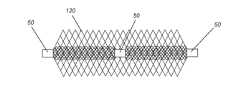
本明細書中に開示される閉塞デバイスは、各キャリッジ20の各端部に別個の挟持点10を有する一連の圧縮可能なメッシュキャリッジ20を含む。この点において、閉塞デバイス設計は1つの連続的な3次元メッシュ網であり、動脈瘤90又は体腔内に留置されると、血流阻止、血栓形成、細胞成長のための枠組み及び/又は最終的な血行静止を提供する。請求される発明の目的において、「キャリッジ」20は、各挟持点10又は各マーカー50に囲み覆われている挟持点10間のメッシュの軸方向区分である。「挟持点」10
は、メッシュの軸方向区分の端部に配置され、この端部を画定する。このような区分化されたメッシュキャリッジ20及び挟持点10は、多くの場合、連続的なメッシュ構造体又は網内にある。「挟持点」はメッシュ構造体の、拘束され、まとめられた位置として、離れた場所にある隣接するキャリッジの移動を制限するように機能し、それによってキャリッジを互いに安定させる。これらキャリッジ20の数(n)は臨床的及び実用的に可能な限り多く、大きな及び/又は不規則な大きさの動脈瘤90を処置するための、並びに約150センチメートル(cm)のカテーテル70(又はマイクロカテーテル)を通じて送出するための既知の診断技術に従い臨床医によって予め決定される。各キャリッジ20の長さ(x)30は、長さ(x)30が「遊離ガス」中においてキャリッジ20を寸法y(幅40)に拡張させるのに十分である限りは、所与の大きさの動脈瘤90を閉塞するのに適切と考えられるキャリッジ20の数(n)に応じて変えることができる。当技術分野で容認されている通り、このような閉塞デバイスの直径は遊離ガス中で測定される。各キャリッジ20の幅(y)40は、臨床的に実現可能であるためには、(遊離ガス中において)約2ミリメートル(mm)~約50mmの範囲である。留置されると、キャリッジ20は、y40の寸法のキャリッジ20がy40の約2倍(又は2y)に増大することができるように、直径又は幅(y)40が約2倍まで増大する又は拡張するような状態で圧縮する。換言すると、各キャリッジ20はマシュマロのように圧縮して、x30の減少及びy40の拡大を生じさせる。一実施形態では、遊離ガス中において、各キャリッジ20はx30がy40より大きい又はy40に等しいような状態に設計され得るが、留置(圧縮)形状においては、y40はx30よりも大きい。一連の圧縮可能なキャリッジ20を含むこのような閉塞デバイスは、キャリッジ20の数(n)並びに各キャリッジ20の長さ(x)30及び幅(y)40を、処置される広範な大きさ及び形状の動脈瘤90又は体腔に適応するように選択するために、調節可能な状態で構成され得る。したがって、別の実施形態では、遊離ガス中において、各キャリッジ20はx30がy40以下であるような状態に設計することができ、留置(圧縮)形状においては、y40はx30よりも大きなままである。The occlusion device disclosed herein includes a series of
are placed at and define the ends of the axial sections of the mesh. Such
一実施形態では、デバイスは、ニチノール(NiTi)、コバルトクロム(CoCr)合金、ステンレス鋼、タングステンイリジウム合金、又はこれらの組み合わせなどであるがこれらに限定されない容易に入手可能な材料の金属ブレードで作製されている。例えば、メッシュキャリッジ20は、わずか36本のブレードから144本ものブレードの範囲内の、臨床的に最も適切且つ実用的な編組メッシュで織られている。別の実施形態では、金属ブレード構造の編み目の角度によって最も軟質の圧縮可能メッシュ設計を作成する。例えば、メッシュは、約0.0075インチ~約0.005インチの直径のワイヤで編み込まれる。したがって、本明細書中に開示される閉塞デバイスは、一連の超軟質の軸方向に圧縮可能なメッシュキャリッジ20であり、nは、単一の閉塞デバイス内のメッシュキャリッジ20の数である。「n」キャリッジを有するこのような閉塞デバイスを使用する前に、臨床医又は医師は容易に利用可能な診断技術を使用して、処置される動脈瘤又は体腔の大きさ及び形状を特定する。医師又は臨床医は、その後、所与の動脈瘤又は体腔を最適に処置するために使用される所望の数(n)のキャリッジ及びキャリッジの種々の大きさを有する閉塞デバイスを最適に選択することができる。 In one embodiment, the device is made of metal blades of readily available materials such as, but not limited to, nitinol (NiTi), cobalt chromium (CoCr) alloys, stainless steel, tungsten iridium alloys, or combinations thereof. It is For example, the
図1Aは、単一のメッシュキャリッジ20の例示的実施形態を示し、単一のメッシュキャリッジ20はその遊離ガス中における幅(y)40よりも大きな軸方向長さ(x)30を有し、キャリッジ20の各端部は挟持点10である。別の実施形態では、軸方向キャリッジ20はその遊離ガス中における幅(y)40に等しい軸方向長さ(x)30を有し得る。更に別の実施形態では、軸方向キャリッジ20はその遊離ガス中における幅(y)40よりも短い軸方向長さ(x)30を有し得る。図1Bは、連続的な圧縮可能なメッシュ構造体である一連の軸方向メッシュ区分化キャリッジ20の一実施形態を示し、n=3の軸方向メッシュキャリッジ20であり、各挟持点10はマーカー50によって囲み覆われ
ている。「マーカー」は周知であり、医療デバイス技術において容易に利用可能である。いくつかの実施形態では、マーカーは、金属材料、多くの場合、放射線不透過性材料からなり、閉塞デバイスの挟持点を囲み覆うためにバンド形マーカー、リング形マーカー、チューブ形等などの形状を取る。あるいは、マーカーは、所与の挟持点に巻回され、そのため、所与の挟持点を覆い囲んでいるワイヤストランドからなってもよい。一実施形態では、各挟持点10を囲み覆うマーカー50は、デバイスがカテーテル70(又はマイクロカテーテル)内のどこにあるか、及びデバイスが動脈瘤90又は体腔内に留置後どこにあるかに関し、X線下での位置的基準を提供する。図2は、連続的な圧縮可能なメッシュ構造体である一連の可変寸法の(寸法及び/又は直径が異なる)区分化軸方向メッシュキャリッジ20の例示的実施形態を示し、n=3の軸方向メッシュキャリッジ20であり、各キャリッジ20は、x30及びy40の寸法に関して異なり、各挟持点10はマーカー50によって囲み覆われている。図2に示すこのような構成では、動脈瘤90に入る第1のキャリッジ20(右側)は、処置される動脈瘤90の最大測定直径よりもわずかに大きな直径又は幅(y)40を有し、デバイスの連続的なメッシュ構造体が動脈瘤90の壁の最も薄く且つ最も敏感な領域であることが多い動脈瘤90のドームに接触しないようにする。加えて、図2に示すこの構成では、動脈瘤90に入る最後のキャリッジ20(左側)の直径又は幅(y)40は動脈瘤頚部100よりも大きく、この最後のキャリッジ20を動脈瘤90内部にしっかりと固定された(及び留められた)ままにする。FIG. 1A shows an exemplary embodiment of a
図3は、デバイスの拘束されたメッシュキャリッジ20がカテーテル70ルーメン内に装填された状態の、本明細書中に開示される閉塞デバイスの一実施形態を示す。デバイスは電解離脱領域80を有する電解プッシャワイヤ60によって進められ、留置されると、キャリッジ20はカテーテル70の先端を出る際に拡張し、動脈瘤90又は体腔の容積を占める。次の軸方向キャリッジ20が動脈瘤90内に留置されると、軸方向キャリッジ20は互いに圧縮し、動脈瘤90を充填することで、動脈瘤90又は体腔内部に一連の層及び/又は区画を形成して血流を阻害し、最終的には血行静止をもたらす。 FIG. 3 shows one embodiment of the occlusion device disclosed herein with the constrained
図4は、処置される動脈瘤90内に留置された、本明細書中に開示される閉塞デバイスの一実施形態を示す。圧縮可能なメッシュキャリッジ20は、動脈瘤90嚢内部に複数の区画化層を形成する。この留置形状において、軸方向キャリッジ20は、動脈瘤90又は体腔を、層若しくは区画として充填し、それによって、留置後の軸方向長さ(x)30を、その遊離ガス中における軸方向長さ30の比率に対して変化させる。例えば、留置後の軸方向長さ(x)30は、遊離ガス中における軸方向長さ30の約5%~約50%である。 FIG. 4 shows one embodiment of the occlusion device disclosed herein deployed within an
図9及び図10は、本明細書中に開示される閉塞デバイスの実施形態を示す。このような実施形態では、遠位キャリッジ20(図9及び図10の上部キャリッジ20)は動脈瘤90内へと拡張して、可変寸法のより小さな次のキャリッジ20が押すための安定構造を形成し、これにより、デバイスが動脈瘤頚部100を横断して(又は動脈瘤頚部100内に)配置される際にデバイスを安定させる。このような構成及び一実施形態では、キャリッジ20の間にある挟持点10及び/又はマーカー50に続く遠位キャリッジ20の砂時計形様の形状130はデバイスの全体的な安定性に寄与する。別の実施形態では、遠位キャリッジ20の砂時計形様の形状130は、それ自体の内側に凹むのではなくむしろ、次のキャリッジ20の方へと外側を向く突起によって画定される。図9及び図10は、力の分配を矢印によって示す。力(F)によって、遠位キャリッジ20に力又は圧力を分配し、これにより、デバイスを動脈瘤90内の適所に安定的に埋め込み、固定する。図2に示す一連のキャリッジ20の他の可変構成と同様に、図10は、動脈瘤90に入る最後のキャリッジ20の直径又は幅(y)40が動脈瘤頚部100よりも大きく、この最後のキャリッジ20を動脈瘤90内部にしっかりと固定した(及び留めた)ままにして血流を阻害し、最終的に血行静止をもたらすことを示す。 Figures 9 and 10 illustrate embodiments of the occlusive devices disclosed herein. In such embodiments, the distal carriage 20 (
理論に拘束されることを望むものではないが、この、軸方向キャリッジ20の区分に分割されている連続的な圧縮可能なメッシュ構造体の構成は、動物研究において、デバイスの急性血栓形成性の向上に寄与すると考えられる作用機序を引き起こす。また、ワイヤストランドが表面積に大きく寄与する一連のキャリッジ20層及び区画の間に小体積の凝塊を局所化することで、動脈瘤90内の血栓の凝集及び安定化を促進すると考えられる。動脈瘤の頚部100を横断して分配された又はその内部に分配されたメッシュ構造体に血液が圧力をかけることから、この閉塞デバイスのその留置形状における区画化は、留置されたデバイスの効果的な安定又は固定機能である。このような構成は、また、末梢動脈又は静脈閉塞のために、動脈瘤90壁又は血管壁に対する圧縮可能なデバイスの十分な並置を提供する。本明細書中に開示されるデバイスは、血行静止を急性に与えるほど十分なメッシュ密度を提供し、留置時、ワイヤメッシュ/ブレードの分布は比較的均一なままである。 While not wishing to be bound by theory, this configuration of a continuous compressible mesh structure divided into segments of
本明細書中に開示される閉塞デバイスの別の実施形態では、圧縮可能な軸方向メッシュキャリッジ20は、72本のNiTiワイヤメッシュストランドブレード構成又は72本のNiTi及びCoCrワイヤメッシュストランドブレード構成の組み合わせなどであるが、これらに限定されないワイヤメッシュストランド又はブレードの比較的均一な分布を含む。他の実施形態では、閉塞デバイスは、36~144本の範囲のNiTiストランドブレード構成のワイヤメッシュストランド又はブレードを含む。 In another embodiment of the occlusive device disclosed herein, the compressible
図5は、1つの同軸内部メッシュキャリッジ120を含む単一の圧縮可能な軸方向メッシュキャリッジ20を示す。図6は、複数の同軸内部メッシュキャリッジ120を含む単一の軸方向メッシュキャリッジ20を示す。このような同軸メッシュ内部120又は同軸メッシュ内部120は、同軸メッシュ内部キャリッジ120のない軸方向メッシュキャリッジ20よりも大きな血流阻止及び区画化を生じさせ、これにより血行静止及び血栓安定化をもたらす。別の実施形態では、軸方向キャリッジ20及び1つの同軸キャリッジ120(又は複数のキャリッジ)は異種金属メッシュで構成されている。更なる実施形態では、異種金属メッシュは、血栓の発生を更に高めることができるガルバニック効果を生じさせる。別の更なる実施形態では、異種金属メッシュは、他のキャリッジ20、120の金属に対し放射線不透過性特性を有することでデバイスの可視化を向上する、1つのキャリッジ20内の1つの金属を含み得る。このような実施形態では、ブレードメッシュ密度は軸方向外部キャリッジ20と同軸内部キャリッジ120とで同じであっても異なっていてもよく、内部メッシュのワイヤと外部メッシュのワイヤは異なる数のストランド及びワイヤ径を有することができる。このような1つの同軸キャリッジ又は複数の同軸キャリッジ120は外部軸方向キャリッジ20に比べて寸法が様々である。例えば、一実施形態では、1つの同軸キャリッジ又は複数のキャリッジ120は、1つの同軸キャリッジ又は複数の同軸キャリッジ120を中に含む外部軸方向キャリッジ20の寸法の約5%~約95%の範囲であり得る。図7は、カテーテル70ルーメン内に装填された軸方向キャリッジ20及び同軸キャリッジ120を示し、図8は、電解離脱式プッシャワイヤ60による電解デバイス留置及びカテーテル70の先端を出るキャリッジ20、120(外部及び内部)の拡張を示す。 FIG. 5 shows a single compressible
一実施形態では、リングなどのマーカー50が、連続的なメッシュ構造体の各キャリッジ20、120の各端部を画定する挟持点10を囲み覆っている。したがって、本明細書中に開示される閉塞デバイスのマーカー50は、金、白金、ステンレス鋼及び/又はこれらの組み合わせなどであるが、これらに限定されない材料を含む中実リング又はバンドなどであるが、これに限定されない実質的に中実のカラー又は剛性部材である。別の実施形態では、金、白金、白金/イリジウム合金及び/又はこれらの組み合わせなどであるが、これらに限定されない放射線不透過性材料が使用され得る。このようなマーカー50は、
送出及び配置時におけるデバイスの位置の可視化を提供する。マーカー50は、各キャリッジ20、120の各端部にある挟持点10を覆い囲むように閉塞デバイス上に配置されている。このように、近位キャリッジ20、120の近位端にあるマーカー50は、動脈瘤90の頚部100の上方又は内部に載置することが可能である。マーカー50の中実性によって、動脈瘤90内におけるデバイスの安定性を付与し、圧縮可能なメッシュキャリッジ20、120を介した力の移動又は伝達を防止することで、デバイスの誤配置又は偶発的な移動を防ぐ。マーカー50はまた、送出カテーテル70又はガイドワイヤ60及び/若しくはプッシャワイヤ技術などであるが、これらに限定されない対応する送出手段と連係し、送出手段から解放する/送出手段に取り付けるための接合部を備えて構成されている。マーカー50はまた、有利には、本明細書中に開示されるデバイスの完全回収可能性を提供する。In one embodiment,
Provides visibility of device position during delivery and placement. A
別の実施形態では、実質的に中実のマーカー50は、放射線不透過性材料(例えば、白金、金、白金/イリジウム合金及び/又はこれらの組み合わせなどであるがこれらに限定されない)を含み、送出、配置及び/又は留置時における蛍光透視下での閉塞デバイスの可視化を容易にする。マーカー50は近位端及び遠位端を含む。本明細書中に開示される閉塞デバイスは、留置中に拡張する際、圧縮可能なキャリッジ20、120の形状、直径及び/又は湾曲に影響するようマーカーの使用を組み込むように構成してもよい。加えて、マーカー50は、動脈瘤90嚢内で拡張/留置された閉塞デバイスの適切な適合を確実にするための一連のメッシュキャリッジ20、120を有する、閉塞デバイスの全体的な外形に影響するような種々の形状で設計してもよい。 In another embodiment, the substantially
図3、図7及び図8は、本明細書中に開示される閉塞デバイスを、動脈瘤90又は体腔に隣接する動脈及び/又は血管110を通じて、電解送出及び/又は留置及び/又は離脱するための例示的な手段を示す。米国特許第5,122,136号明細書などの電解離脱手段及び方法が当技術分野では周知である。一実施形態では、カテーテル70(又はマイクロカテーテル)のコイルが巻かれたコアワイヤ60(又はガイドワイヤ又はプッシャワイヤ)の最遠位端がマーカー50内部で本明細書中に開示される閉塞デバイス(図3、図7及び図8に示すような)に取り付けられている。コイルの巻きは、送出カテーテル70又はマイクロカテーテル又はガイドワイヤ60の可撓性又は剛性に影響しないように一定直径(φ)を維持する。ある実施形態では、FEP(フッ化エチレンプロピレン)熱収縮チューブが、コアワイヤのコイルが巻かれた部分を覆っている。医療デバイス技術における多くの容易に利用可能且つ周知の取付技術を使用して、コアワイヤの遠位端をマーカー内部に、及び閉塞デバイス又はインプラントに取り付けることができる。このような取付技術としては、接着剤、レーザー溶融、レーザー粘着、スポット溶接及び/又は連続溶接が挙げられるが、これらに限定されない。一実施形態では、コアワイヤの遠位端をマーカー内部に取り付けるために接着剤が使用される。更なる実施形態では、接着剤は、熱又はUV(紫外線)放射の適用によってキュア又は硬化されるエポキシ材料である。更に別の実施形態では、エポキシは、14 Fortune Drive,Billerica,Mass.所在のEpoxy Technology,Inc.から入手可能なEPO-TEK(登録商標)353ND-4などの熱硬化型2液エポキシである。このような接着剤又はエポキシ材料は、マーカー50内部のコアワイヤの接合部を被覆し、その機械的安定度を高める。 FIGS. 3, 7 and 8 are for electrolytic delivery and/or deployment and/or withdrawal of the occlusion devices disclosed herein through an artery and/or
別の実施形態では、デバイスの留置中及び/又は留置後、コイルが巻かれたコアワイヤ60は自動的に、本明細書中に開示される閉塞デバイスを、コアワイヤ60がマーカー50の基部における電解作用によって切断される及び/又は溶解されるような状態で、コアワイヤ60の電解離脱位置80(又は領域)において離脱する。このような作用により、その後、処置される動脈瘤90又は血管内に閉塞デバイスを解放する及び/又は配置する。 In another embodiment, during and/or after placement of the device, the coiled
ある実施形態では、本明細書中に開示される閉塞デバイスの圧縮可能なメッシュ構造体には、動脈瘤90の凝固及び閉鎖を促進するための塞栓材料が充填され得る。 In certain embodiments, the compressible mesh structure of the occlusion devices disclosed herein can be filled with embolic material to facilitate coagulation and closure of the
他の実施形態では、本明細書中に開示される閉塞デバイスは、コイリング技術、フレーミングコイル、塞栓物質、付加的なマーカー、ポリマー、吸収ポリマー及び/又はこれらの組み合わせなどの付属的要素及び/又は部材を更に組み込んでもよい。 In other embodiments, the occlusive devices disclosed herein include ancillary elements such as coiling techniques, framing coils, embolic material, additional markers, polymers, absorbable polymers and/or combinations thereof and/or Additional members may be incorporated.
閉塞デバイスの設計及び/又は製造のための弾性及び圧縮可能なメッシュ材料は容易に入手可能であり、当業者には周知である。したがって、弾性及び圧縮可能なメッシュ材料は、ニッケルチタン(ニチノール又はそうでなければNiTiとして知られている)、ステンレス鋼、ポリマー、及び/又はこれらの組み合わせなどであるが、これらに限定されない広範な入手可能材料に及ぶ。例示的な既知のバイオメディカルポリマー類としては、ポリホスファゼン、ポリ酸無水物、ポリアセタール、ポリ(オルトエステル)、ポリホスホエステル、ポリカプロラクトン、ポリウレタン、ポリラクチド、ポリカーボネート、ポリアミド及び/又はこれらの組み合わせなどのポリマーが挙げられるが、これらに限定されない。(例えば、J Polym Sci B Polym Phys.Author
manuscript;PMC 2012 June 15で入手可能、を参照のこと。)Resilient and compressible mesh materials for the design and/or manufacture of occlusive devices are readily available and well known to those skilled in the art. Accordingly, a wide variety of elastic and compressible mesh materials include, but are not limited to, nickel titanium (nitinol or otherwise known as NiTi), stainless steel, polymers, and/or combinations thereof. Ranging from available materials. Exemplary known biomedical polymers include polyphosphazenes, polyanhydrides, polyacetals, poly(orthoesters), polyphosphoesters, polycaprolactones, polyurethanes, polylactides, polycarbonates, polyamides, and/or combinations thereof. Polymers include, but are not limited to. (For example, J Polym Sci B Polym Phys. Author
See manuscript; available at PMC 2012 June 15. )
一例示的実施形態では、弾性及び圧縮可能なメッシュ材料は、ナイロン、ポリプロピレン、又はポリエステルなどであるが、これらに限定されないポリマー材料の織られたストランドで形成されている。ポリマーストランドには放射線不透過性材料を充填することができ、血管系内におけるデバイスの位置を、動脈瘤を処置する医師が透視下で視認することを可能にする。放射線不透過性充填材としては、好ましくは、三酸化ビスマス、タングステン、二酸化チタン若しくは硫酸バリウム、又はヨウ素などの放射線不透過性色素が挙げられる。弾性及び圧縮可能なメッシュ材料は放射線不透過性材料のストランドによって形成され得る。放射線不透過性ストランドは、医師及び/又は放射線専門医が充填ポリマー材料を使用することなくメッシュの位置を透視下で視認することを可能にする。このような放射線不透過性ストランドは、金、白金、白金/イリジウム合金及び/又はこれらの組み合わせなどであるが、これらに限定されない材料で形成されていてもよい。一実施形態では、弾性メッシュ材料は10%~45%白金コアNiTiで構成されている。別の実施形態では、弾性メッシュ材料は、10%白金コアNiTi、15%白金コアNiTi、20%白金コアNiTi、又は45%白金コアNiTiで構成されている。X線下で閉塞デバイスのゴースト像を提供するには10%白金コアNiTi構造で十分である。 In one exemplary embodiment, the elastic and compressible mesh material is formed of woven strands of polymeric material such as, but not limited to, nylon, polypropylene, or polyester. The polymer strands can be filled with a radiopaque material, allowing the location of the device within the vasculature to be visualized under fluoroscopy by the physician treating the aneurysm. Radiopaque fillers preferably include radiopaque dyes such as bismuth trioxide, tungsten, titanium dioxide or barium sulfate, or iodine. The elastic and compressible mesh material may be formed by strands of radiopaque material. The radiopaque strands allow physicians and/or radiologists to view the location of the mesh under fluoroscopy without the use of filler polymeric materials. Such radiopaque strands may be formed of materials such as, but not limited to, gold, platinum, platinum/iridium alloys and/or combinations thereof. In one embodiment, the elastic mesh material is composed of 10% to 45% platinum core NiTi. In another embodiment, the elastic mesh material is composed of 10% platinum core NiTi, 15% platinum core NiTi, 20% platinum core NiTi, or 45% platinum core NiTi. A 10% platinum core NiTi structure is sufficient to provide a ghost image of an occlusive device under X-ray.
このように構成された、放射線不透過性コアと非放射線不透過性外層又はケーシングとを有するワイヤ又は複合ワイヤの組み合わせは容易に入手可能であり、医療デバイス及び金属技術においては、DFT(登録商標)(延伸充填管)ワイヤ、ケーブル、又はリボンとして周知である。DFT(登録商標)ワイヤは、2つ以上の材料の所望の物理的及び機械的特性を1つのワイヤに組み合わせるように構成された金属-金属複合材である。より放射線不透過性であるがより延性のある材料をワイヤのコアに配置することにより、NiTi外層は、得られる複合ワイヤに100%NiTiワイヤと類似の機械的特性を付与することができる。DFT(登録商標)ワイヤは、Fort Wayne,Ind.,U.S.A.に所在のFort Wayne Metals Corp.から入手可能である。例えば、参照により本明細書中に組み込む、Schafferによる、Advanced Materials & Processes,Oct 2002,pages 51-54のBiocompatible Wireと題される論文も参照されたい。 Wires or composite wire combinations having a radiopaque core and a non-radiopaque outer layer or casing configured in this manner are readily available and are widely used in medical devices and metals technology by DFT® ) (stretch-filled tube) wire, cable, or ribbon. DFT® wire is a metal-metal composite constructed to combine the desired physical and mechanical properties of two or more materials into one wire. By placing a more radiopaque but more ductile material in the core of the wire, the NiTi outer layer can impart similar mechanical properties to the resulting composite wire as 100% NiTi wire. DFT® wire is available from Fort Wayne, Ind. , U. S. A. of Fort Wayne Metals Corp. available from See also, eg, the article by Schaffer entitled Biocompatible Wire, Advanced Materials & Processes, Oct 2002, pages 51-54, which is incorporated herein by reference.
圧縮可能なメッシュ構造体が放射線不透過性金属ストランドで形成されている場合、ス
トランドはポリマーコーティング又は押出品で被覆されてもよい。放射線不透過性ワイヤストランドを覆うコーティング又は押出品はX線透視可視化を提供するが、曲げ疲労に対するストランドの抵抗も増加させるとともに、ストランドの潤滑性も高めてよい。一実施形態では、ポリマーコーティング又は押出品は、コーティングされている又はへパリンなど抗凝固の傾向がある薬剤で処理されている。このような抗凝塊コーティングは全般に知られている。ポリマーコーティング又は押出品は、任意の適切な押出可能なポリマー、又はTeflon(登録商標)若しくはポリウレタンなどの薄いコーティングで適用することができる任意のポリマーであり得る。If the compressible mesh structure is formed of radiopaque metal strands, the strands may be coated with a polymer coating or extrusion. A coating or extrusion over the radiopaque wire strands provides fluoroscopic visualization, but also increases the resistance of the strands to bending fatigue and may also increase the lubricity of the strands. In one embodiment, the polymer coating or extrudate is coated or treated with an agent that tends to anticoagulate, such as heparin. Such anticoagulant coatings are generally known. The polymeric coating or extrudate can be any suitable extrudable polymer or any polymer that can be applied in a thin coating such as Teflon® or polyurethane.
更に別の実施形態では、圧縮可能なメッシュ構造体のストランドは、金属編組ストランド及びポリマー編組ストランドの両方を使用して形成されている。金属ストランドをポリマーストランドと組み合わせてブレードにすることでメッシュの可撓性特性が変化する。このようなメッシュ部分を留置する及び/又はつぶすために必要な力は、金属メッシュストランドのみを含むメッシュ部分に必要な力に比べて大幅に低下する。しかしながら、X線透視可視化のためのメッシュの放射線不透過性特性は維持される。このようなデバイスを形成する金属ストランドとしては、ステンレス鋼、金、白金、白金/イリジウム、ニチノール及び/又はこれらの組み合わせが挙げられるが、これらに限定されない。デバイスを形成するポリマーストランドとしては、ナイロン、ポリプロピレン、ポリエステル、Teflon(登録商標)及び/又はこれらの組み合わせが挙げられ得る。更に、メッシュ材料のポリマーストランドはこれを放射線不透過性にするために、ポリマーストランドへの金蒸着の使用、又はポリマーストランドへの適切な金属イオンのイオンビームプラズマ蒸着の使用などであるが、これらに限定されない周知の技術によって化学修飾することができる。 In yet another embodiment, the strands of the compressible mesh structure are formed using both metallic braided strands and polymeric braided strands. Combining metal strands with polymer strands into braids alters the flexibility properties of the mesh. The force required to deploy and/or collapse such mesh portions is significantly reduced compared to the force required for mesh portions containing only metal mesh strands. However, the radiopaque properties of the mesh for fluoroscopic visualization are maintained. Metal strands forming such devices include, but are not limited to, stainless steel, gold, platinum, platinum/iridium, nitinol, and/or combinations thereof. Polymer strands forming the device may include nylon, polypropylene, polyester, Teflon® and/or combinations thereof. Further, the polymer strands of the mesh material are made radiopaque, such as using gold vapor deposition on the polymer strands, or ion beam plasma deposition of suitable metal ions on the polymer strands. can be chemically modified by well-known techniques, including but not limited to
圧縮可能なメッシュ構造体は、また、様々な直径及び/又は様々な可撓性のフィラメント又はストランドで形成され得る。例えば、本明細書中に開示される閉塞デバイスで使用するためのワイヤ径は、約0.0075インチ~約0.005インチの範囲である。ポリマーストランドの大きさ又は可撓性を変えることによって、留置時におけるメッシュの可撓性特性も変えることができる。可撓性特性を変えることによって、弾性及び圧縮可能なメッシュ構造体の留置(圧縮)構成及び送出(拘束)構成の両方を実質的にあらゆる所望の形状に変える又は変化させることができる。 A compressible mesh structure may also be formed of filaments or strands of varying diameters and/or varying flexibility. For example, wire diameters for use in the occlusive devices disclosed herein range from about 0.0075 inch to about 0.005 inch. By varying the size or flexibility of the polymer strands, the flexibility characteristics of the mesh during deployment can also be varied. By varying the flexibility properties, both the deployment (compression) and delivery (constraint) configurations of the elastic and compressible mesh structure can be changed or varied into virtually any desired shape.
メッシュは、ポリマーストランド又はフィラメントと金属ストランド又はフィラメントの両方で形成できるだけでなく、異なるポリマー材料のフィラメントを使用して形成することもできる。例えば、異なる可撓性特性を有する異なるポリマー材料を使用してメッシュを形成することができる。これにより、可撓性特性を変更し、結果として生じる、留置状態及びつぶれた状態の両方におけるメッシュ構造体の構成を変化させる。このようなバイオメディカルポリマーは既知であり、当技術分野において利用可能であり、ポリホスファゼン、ポリ酸無水物、ポリアセタール、ポリ(オルトエステル)、ポリホスホエステル、ポリカプロラクトン、ポリウレタン、ポリラクチド、ポリカーボネート、ポリアミド、及び/又はこれらの組み合わせなどであるが、これらに限定されないポリマー類から得ることができる。 The mesh can be formed from both polymeric strands or filaments and metal strands or filaments, as well as using filaments of different polymeric materials. For example, different polymeric materials with different flexibility properties can be used to form the mesh. This alters the flexibility properties and the resulting configuration of the mesh structure in both the deployed and collapsed states. Such biomedical polymers are known and available in the art and include polyphosphazenes, polyanhydrides, polyacetals, poly(orthoesters), polyphosphoesters, polycaprolactones, polyurethanes, polylactides, polycarbonates, polyamides. , and/or combinations thereof, such as, but not limited to, polymers.
メッシュキャリッジ内での使用に好適な圧縮可能なメッシュ材料は、平坦な織られたシート、編まれたシート、又はレーザー切断されたワイヤメッシュの形態を取ってもよい。概して、材料は、実質的に平行なストランドの2つ以上のセットを含むべきであり、平行なストランドの1つのセットは、平行なストランドの他方のセットに対して45度~135度のピッチにある。いくつかの実施形態では、メッシュ材料を形成する平行なストランドの2つのセットは互いに実質的に垂直である。メッシュ材料のピッチ及び全体的な構造は閉塞デバイスの性能要求を満たすように最適化してもよい。 Compressible mesh materials suitable for use in the mesh carriage may take the form of flat woven sheets, knitted sheets, or laser cut wire mesh. In general, the material should include two or more sets of substantially parallel strands, one set of parallel strands at a pitch of 45 degrees to 135 degrees with respect to the other set of parallel strands. be. In some embodiments, the two sets of parallel strands forming the mesh material are substantially perpendicular to each other. The pitch and overall structure of the mesh material may be optimized to meet the performance requirements of the occlusive device.
本明細書中に開示される閉塞デバイスで使用される金属ファブリックのワイヤストランドは、弾性及び圧縮可能の両方であり、熱処理を施して所望の形状を実質的に設定することができる材料で形成すべきである。この目的に適していると考えられる材料としては、閉塞デバイスの分野ではElgiloy(登録商標)と呼ばれるコバルト系低熱膨張合金、Haynes Internationalにより商品名Hastelloy(登録商標)で市販されているニッケル系高温高強度「超合金」、International Nickelにより名称Incoloy(登録商標)で販売されているニッケル系熱処理型合金、及びいくつかの異なるグレードのステンレス鋼が挙げられる。ワイヤに好適な材料を選択する上での重要な要素は、所定の熱処理に曝されたときに成形表面(又は以下に記載されるように形状記憶)によって誘発される適切な変形量をワイヤが維持することである。 The metal fabric wire strands used in the occlusive devices disclosed herein are formed of a material that is both elastic and compressible and that can be heat treated to substantially set a desired shape. should. Materials considered suitable for this purpose include a cobalt-based low thermal expansion alloy called Elgiloy® in the field of occlusive devices; These include strength "superalloys", nickel-based heat treatable alloys sold under the name Incoloy® by International Nickel, and several different grades of stainless steel. An important factor in selecting a suitable material for the wire is whether the wire will undergo the appropriate amount of deformation induced by the forming surface (or shape memory as described below) when subjected to a given heat treatment. to maintain.
これら条件を満たす1つの材料クラスはいわゆる形状記憶合金である。このような合金は、温度によって誘発される相変化を有する傾向があり、これにより材料は、特定の転移温度を超えて材料を加熱し材料の相の変化を誘発することにより固定され得る好適な構成を有する。合金が冷却されると、合金は熱処理時の形状を「記憶」し、この同じ及び/又は類似の構成を、このような構成を取らないように拘束されない限りは取る傾向がある。 One class of materials that meets these conditions is the so-called shape memory alloys. Such alloys tend to have temperature-induced phase changes whereby the material can be fixed by heating the material above a certain transition temperature to induce a phase change in the material. have a configuration. As the alloy cools, it "remembers" the shape it had in the heat treatment and tends to adopt this same and/or similar configuration unless constrained to adopt such a configuration.
本明細書中に開示される閉塞デバイスで使用するための1つの特定の形状記憶合金は、ニッケル及びチタンのほぼ化学量論的合金であり、所望の特性を得るために他の微量の他の金属も含んでもよいニチノールである。適切な組成及び取り扱い要件を含むニチノールなどのNiTi合金は当技術分野では周知であり、このような合金については本明細書で詳述する必要はない。例えば、米国特許第5,067,489号明細書及び米国特許第4,991,602号明細書(これら明細書の教示は参照により本明細書中に組み込まれる)は、ガイドワイヤベースの技術における形状記憶NiTi合金の使用について論じている。このようなNiTi合金は好適であるが、この理由は少なくとも一部には、このようなNiTi合金が市販されており、このような合金の取り扱いについては他の周知の形状記憶合金よりも知られているからである。NiTi合金はまた、非常に弾性である。事実、NiTi合金は「超弾性」又は「擬弾性」として知られているとされている。この弾性によって、本明細書中に開示される閉塞デバイスがその留置のために、前の拡張構成に戻る。 One particular shape memory alloy for use in the occlusive devices disclosed herein is a nearly stoichiometric alloy of nickel and titanium, with minor amounts of others to obtain desired properties. Nitinol, which may also contain metals. NiTi alloys such as Nitinol, including suitable composition and handling requirements, are well known in the art and need not be discussed in detail herein. For example, US Pat. No. 5,067,489 and US Pat. No. 4,991,602, the teachings of which are incorporated herein by reference, describe techniques for guidewire-based technology. The use of shape memory NiTi alloys is discussed. Such NiTi alloys are preferred, at least in part because such NiTi alloys are commercially available and handling of such alloys is known more than other known shape memory alloys. because NiTi alloys are also very elastic. In fact, NiTi alloys are said to be known as "superelastic" or "pseudoelastic". This elasticity causes the occlusive device disclosed herein to return to its previous expanded configuration for deployment.
ワイヤストランドは、選択された材料の標準的なモノフィラメントを含み得る、即ち、標準的なワイヤストックを使用してもよい。いくつかの実施形態では、72本のワイヤストランド及び/又は72本のストランドブレード構成が使用される。他の実施形態では、閉塞デバイスは、36~144本の範囲のNiTiストランドブレード構成のワイヤメッシュストランド又はブレードを含む。しかし所望であれば、個々のワイヤストランドを、複数の個々のワイヤで構成された「ケーブル」から形成してもよい。例えば、中心ワイヤの周りにいくつかのワイヤが螺旋状に巻かれた金属ワイヤで形成されたケーブルは市販されており、0.003インチ以下の外径を有するNiTiケーブルは購入することができる。あるケーブルの利点の1つは、同一直径を有し同一材料で形成されたモノフィラメントワイヤよりも「軟質」傾向にあることである。加えて、ケーブルの使用によってワイヤストランドの有効表面積を増すことができ、血栓形成を促進する傾向がある。 The wire strands may comprise standard monofilaments of the material of choice, ie standard wire stock may be used. In some embodiments, 72 wire strands and/or 72 strand braid configurations are used. In other embodiments, the occlusive device comprises wire mesh strands or braids in a NiTi strand braid configuration ranging from 36 to 144 strands. However, if desired, individual wire strands may be formed from a "cable" made up of a plurality of individual wires. For example, cables made of metal wire with several wires helically wound around a central wire are commercially available, and NiTi cables can be purchased with outer diameters of 0.003 inches or less. One advantage of some cables is that they tend to be "softer" than monofilament wires of the same diameter and made of the same material. Additionally, the use of cables can increase the effective surface area of the wire strands, which tends to promote thrombus formation.
本明細書中に開示される閉塞デバイスは、一連の圧縮可能な軸方向キャリッジ20(挟持点10によって画定される)を有する連続的なメッシュ構造体によって構成されており、一連の圧縮可能な軸方向キャリッジ20は、血管又は体腔又は動脈瘤90を充填することで血流を約60%低減して、凝塊形成及び/又は動脈瘤90の治癒及び/又は最終的な血行静止を生じさせる、内皮細胞足場層又は区画のような状態で機能するのに十分なメッ
シュ密度を有する。本明細書中に開示される閉塞デバイスの目的において、用語「メッシュ密度」は、有孔率のレベル又はメッシュ構造体の開口面積に対する金属の比率を意味する。メッシュ密度は、メッシュの開口又は孔の数及び大きさ、並びに開口又は孔の開口状態が送出と留置との間で変化する状況において孔が開放又は閉鎖している程度に関係する。概して、弾性メッシュ材料の高メッシュ密度領域は概ね約40%以上の金属面積及び約60%以下の開口面積を有する。The occlusive device disclosed herein is constructed by a continuous mesh structure having a series of compressible axial carriages 20 (defined by pinch points 10), and a series of compressible axial The
いくつかの実施形態では、圧縮可能なメッシュ構造体は、同一材料で均一に形成されていてもよい。しかしながら、このような材料は、異なる編まれた、縫われた、編組された及び/又は切断された構造を有してもよい。 In some embodiments, the compressible mesh structure may be uniformly formed of the same material. However, such materials may have different knitted, stitched, braided and/or cut constructions.
他の実施形態では、本明細書中に開示される植え込み型閉塞デバイスは、例えば、末梢動脈又は静脈の病状及び/又は処置のために血管閉塞を必要とする任意の関連の病状の処置及び/又は改善における末梢血管塞栓術のプロセス(当技術分野で周知のプロセスであり、特定血管部位の遠位側における血流停止を伴うことが知られている)に使用され得る。 In other embodiments, the implantable occlusive devices disclosed herein are used for the treatment and/or treatment of, for example, peripheral arterial or venous pathologies and/or any related pathology requiring vascular occlusion for treatment. or in amelioration of the process of peripheral embolization, a process well known in the art and known to involve cessation of blood flow distal to a particular vascular site.
本明細書中に開示される閉塞デバイスは、閉塞デバイスの分野における当業者には自明の合理的な設計パラメータ、特徴、変更形態、利点及び変形形態を組み込んでもよい。 The occlusive devices disclosed herein may incorporate reasonable design parameters, features, modifications, advantages and variations that are apparent to those skilled in the art of occlusive devices.
本明細書中に開示される閉塞デバイスに関する研究実施計画書及び動物使用の正当性は、ISIS ServicesのInstitutional Animal Care
and Use Committee(IACUC)によって検討及び承認され、手順は獣医の監督下で実施した。Protocols and animal use justification for the occlusive devices disclosed herein can be obtained from ISIS Services Institutional Animal Care.
Reviewed and approved by the International and Use Committee (IACUC), the procedure was performed under veterinary supervision.
ウサギエラスターゼ動脈瘤モデルは、新規な神経インターベンションデバイスの試験において広く受け入れられているとともに、当技術分野で承認されているモデルであり、有効性及びヒトの反応に類似することに関して多くの臨床出版物の対象となってきた。(例えば、Altes et al.Creation of Saccular Aneurysms in the Rabbit:A Model Suitable for
Testing Endovascular Devices.AJR 2000;174:349-354を参照のこと。)したがって、このモデルは適切な試験モデルとして規制機関により即座に承認される。このモデルの凝固系はヒトの凝固系と酷似している。加えて、このモデルは、ウサギの頭蓋外頚動脈の直径がヒトの頭蓋外頚動脈の直径と酷似しているという点で有利な解剖学的側面を有する。更に、エラスターゼ誘起動脈瘤はヒトの動脈瘤と組織学的に類似するように挙動することが示されている。The rabbit elastase aneurysm model is a widely accepted and art-recognized model for testing novel neurointerventional devices, with many clinical publications regarding efficacy and similarity to human response. It has become an object. (See, for example, Altes et al. Creation of Saccular Aneurysms in the Rabbit: A Model Suitable for
Testing Endovascular Devices. See AJR 2000;174:349-354. ) Therefore, this model is immediately approved by regulatory bodies as a suitable test model. The coagulation system of this model closely resembles the human coagulation system. In addition, this model has advantageous anatomical aspects in that the diameter of the rabbit extracranial carotid artery closely resembles that of the human extracranial carotid artery. Furthermore, elastase-induced aneurysms have been shown to behave histologically similar to human aneurysms.
本発明のいくつかの実施形態を記載してきた。本明細書に開示される閉塞デバイスの範囲及び趣旨から逸脱することなく、請求される装置の合理的な特徴、修正形態、利点及び設計の変形形態が、当業者には、先行する詳細な説明及び実施形態に説明したガイドラインに従うことによって容易に明らかとなろう。したがって、他の実施形態は以下の特許請求の範囲の範囲内である。 A number of embodiments of the invention have been described. Without departing from the scope and spirit of the occlusive devices disclosed herein, reasonable features, modifications, advantages and design variations of the claimed apparatus will occur to those skilled in the art from the preceding detailed description. and will be readily apparent by following the guidelines set forth in the embodiments. Accordingly, other embodiments are within the scope of the following claims.
Claims (14)
Translated fromJapanese端部と端部とを繋げて構成された軸方向メッシュ区分を含む連続的な圧縮可能なメッシュ構造体を含み、各軸方向区分の各端部は、前記メッシュ構造体の1つの軸方向区分を前記メッシュ構造体に隣接する隣接軸方向区分に接続し、前記メッシュ構造体の軸方向の動きを制限するように機能する、前記連続的なメッシュ構造体の挟持点であり、少なくとも1つの軸方向区分は、1つの内部同軸メッシュ区分又は複数の内部同軸メッシュ区分を含む外部軸方向キャリッジであり、前記1つの内部同軸メッシュ区分又は前記複数の内部同軸メッシュ区分は前記外部軸方向区分と異なるメッシュ密度であり、
マーカーが少なくとも1つの挟持点を囲み覆っている、
閉塞デバイス。An occlusion device for implantation within an aneurysm, comprising:
a continuous compressible mesh structure comprising axial mesh sections arranged end-to-end, each end of each axial section being one axial section of said mesh structure; to adjacent axial sections adjacent to the mesh structure and function to limit axial movement of the mesh structure, at least one axis The directional section is an outer axial carriage comprising an inner coaxial mesh section or a plurality of inner coaxial mesh sections, said one inner coaxial mesh section or said plurality of inner coaxial mesh sections having a different mesh than said outer axial section. is the density,
the marker surrounds and covers at least one pinch point;
occlusive device.
a.端部と端部とを繋げて構成された軸方向メッシュ区分を含む連続的な圧縮可能なメッシュ構造体を含む、体腔又は動脈瘤内に植え込むための閉塞デバイスであって、各区分の各端部は、前記メッシュ構造体の1つの軸方向区分を前記メッシュ構造体に隣接する隣接軸方向区分に接続し、前記メッシュ構造体の軸方向の動きを制限するように機能する、前記連続的なメッシュ構造体の挟持点である、請求項1に記載の閉塞デバイスと、
b.前記閉塞デバイスに対応する送出システム又は離脱システムと、
を含み、
マーカーが少なくとも1つの挟持点を囲み覆っている、
キット。A kit for treating and/or improving an aneurysm, comprising:
a. An occlusive device for implantation within a body cavity or aneurysm comprising a continuous compressible mesh structure comprising axial mesh segments configured end to end, each end of each segment A section connects one axial section of the mesh structure to an adjacent axial section adjacent to the mesh structure and functions to restrict axial movement of the mesh structure. 2. The occlusive device of claim 1, which is a pinching point of the mesh structure;
b. a delivery or withdrawal system corresponding to the occlusion device;
including
the marker surrounds and covers at least one pinch point;
kit.
ワイヤである、請求項10に記載のキット。11. The kit of Claim 10, wherein the delivery system is a microcatheter, catheter, guidewire, or pusher wire.
Priority Applications (1)
| Application Number | Priority Date | Filing Date | Title |
|---|---|---|---|
| JP2024193393AJP2025013481A (en) | 2015-12-07 | 2024-11-05 | Occlusion Device |
Applications Claiming Priority (4)
| Application Number | Priority Date | Filing Date | Title |
|---|---|---|---|
| US201562264171P | 2015-12-07 | 2015-12-07 | |
| US62/264,171 | 2015-12-07 | ||
| JP2018529554AJP6892188B2 (en) | 2015-12-07 | 2016-12-07 | Blocking device |
| JP2021085824AJP7227307B2 (en) | 2015-12-07 | 2021-05-21 | occlusion device |
Related Parent Applications (1)
| Application Number | Title | Priority Date | Filing Date |
|---|---|---|---|
| JP2021085824ADivisionJP7227307B2 (en) | 2015-12-07 | 2021-05-21 | occlusion device |
Related Child Applications (1)
| Application Number | Title | Priority Date | Filing Date |
|---|---|---|---|
| JP2024193393ADivisionJP2025013481A (en) | 2015-12-07 | 2024-11-05 | Occlusion Device |
Publications (2)
| Publication Number | Publication Date |
|---|---|
| JP2023053112Atrue JP2023053112A (en) | 2023-04-12 |
| JP7584549B2 JP7584549B2 (en) | 2024-11-15 |
Family
ID=57517885
Family Applications (4)
| Application Number | Title | Priority Date | Filing Date |
|---|---|---|---|
| JP2018529554AActiveJP6892188B2 (en) | 2015-12-07 | 2016-12-07 | Blocking device |
| JP2021085824AActiveJP7227307B2 (en) | 2015-12-07 | 2021-05-21 | occlusion device |
| JP2023018404AActiveJP7584549B2 (en) | 2015-12-07 | 2023-02-09 | Occlusion Device |
| JP2024193393APendingJP2025013481A (en) | 2015-12-07 | 2024-11-05 | Occlusion Device |
Family Applications Before (2)
| Application Number | Title | Priority Date | Filing Date |
|---|---|---|---|
| JP2018529554AActiveJP6892188B2 (en) | 2015-12-07 | 2016-12-07 | Blocking device |
| JP2021085824AActiveJP7227307B2 (en) | 2015-12-07 | 2021-05-21 | occlusion device |
Family Applications After (1)
| Application Number | Title | Priority Date | Filing Date |
|---|---|---|---|
| JP2024193393APendingJP2025013481A (en) | 2015-12-07 | 2024-11-05 | Occlusion Device |
Country Status (6)
| Country | Link |
|---|---|
| US (4) | US10285711B2 (en) |
| EP (3) | EP4011303B1 (en) |
| JP (4) | JP6892188B2 (en) |
| CA (1) | CA3005686A1 (en) |
| ES (2) | ES2912136T3 (en) |
| WO (1) | WO2017097862A2 (en) |
Families Citing this family (45)
| Publication number | Priority date | Publication date | Assignee | Title |
|---|---|---|---|---|
| US11484322B2 (en) | 2018-01-03 | 2022-11-01 | Aneuclose Llc | Aneurysm neck bridge with a closeable opening or lumen through which embolic material is inserted into the aneurysm sac |
| US11471163B2 (en) | 2008-05-01 | 2022-10-18 | Aneuclose Llc | Intrasaccular aneurysm occlusion device with net or mesh expanded by string-of-pearls embolies |
| US11464518B2 (en) | 2008-05-01 | 2022-10-11 | Aneuclose Llc | Proximal concave neck bridge with central lumen and distal net for occluding cerebral aneurysms |
| US11471164B2 (en) | 2008-05-01 | 2022-10-18 | Aneuclose Llc | Methods of occluding a cerebral aneurysm by inserting embolic members or material into an intrasacular implant |
| US11357511B2 (en) | 2008-05-01 | 2022-06-14 | Aneuclose Llc | Intrasacular aneurysm occlusion device with globular first configuration and bowl-shaped second configuration |
| US10716573B2 (en) | 2008-05-01 | 2020-07-21 | Aneuclose | Janjua aneurysm net with a resilient neck-bridging portion for occluding a cerebral aneurysm |
| US12004750B2 (en) | 2008-05-01 | 2024-06-11 | Aneuclose Llc | Methods for creating an expandable two-part intrasacular aneurysm occlusion device from a tubular mesh |
| US11583289B2 (en) | 2008-05-01 | 2023-02-21 | Aneuclose Llc | Aneurysm-occluding mesh ribbon with a series of loops or segments having distal-to-proximal variation in size, shape, and/or orientation |
| AU2009242528B2 (en) | 2008-05-02 | 2015-12-10 | Microvention, Inc. | Filamentary devices for treatment of vascular defects |
| US10327781B2 (en) | 2012-11-13 | 2019-06-25 | Covidien Lp | Occlusive devices |
| US10561509B2 (en) | 2013-03-13 | 2020-02-18 | DePuy Synthes Products, Inc. | Braided stent with expansion ring and method of delivery |
| US9955976B2 (en) | 2013-08-16 | 2018-05-01 | Sequent Medical, Inc. | Filamentary devices for treatment of vascular defects |
| US9629635B2 (en) | 2014-04-14 | 2017-04-25 | Sequent Medical, Inc. | Devices for therapeutic vascular procedures |
| US10130372B2 (en) | 2014-04-30 | 2018-11-20 | Cerus Endovascular Limited | Occlusion Device |
| US10206796B2 (en) | 2014-08-27 | 2019-02-19 | DePuy Synthes Products, Inc. | Multi-strand implant with enhanced radiopacity |
| CA2976260C (en) | 2015-02-25 | 2024-02-06 | Galaxy Therapeutics, Llc | System for and method of treating aneurysms |
| EP4011303B1 (en)* | 2015-12-07 | 2024-06-12 | Cerus Endovascular Limited | Occlusion device |
| WO2017153603A1 (en) | 2016-03-11 | 2017-09-14 | Cerus Endovascular Limited | Occlusion device |
| EP3463109A4 (en) | 2016-05-26 | 2020-01-08 | Nanostructures, Inc. | System and methods for embolized occlusion of neurovascular aneurysms |
| US10076428B2 (en) | 2016-08-25 | 2018-09-18 | DePuy Synthes Products, Inc. | Expansion ring for a braided stent |
| US10292851B2 (en) | 2016-09-30 | 2019-05-21 | DePuy Synthes Products, Inc. | Self-expanding device delivery apparatus with dual function bump |
| US10576099B2 (en) | 2016-10-21 | 2020-03-03 | Covidien Lp | Injectable scaffold for treatment of intracranial aneurysms and related technology |
| AU2018239680A1 (en) | 2017-03-24 | 2019-10-10 | Artio Medical, Inc. | Medical devices comprising detachable balloons and methods of manufacturing and use |
| JP7414710B2 (en)* | 2017-08-21 | 2024-01-16 | シーラス エンドバスキュラー リミテッド | occlusion device |
| KR20200038886A (en)* | 2017-09-01 | 2020-04-14 | 메타랙티브 메디컬, 인크. | Medical devices and methods of manufacture and use comprising removable balloons |
| US11185335B2 (en) | 2018-01-19 | 2021-11-30 | Galaxy Therapeutics Inc. | System for and method of treating aneurysms |
| CN111936063B (en)* | 2018-01-31 | 2024-08-20 | 纳米结构公司 | Vascular occlusion device utilizing thin film nitinol foil |
| AU2019204522A1 (en) | 2018-07-30 | 2020-02-13 | DePuy Synthes Products, Inc. | Systems and methods of manufacturing and using an expansion ring |
| US10456280B1 (en) | 2018-08-06 | 2019-10-29 | DePuy Synthes Products, Inc. | Systems and methods of using a braided implant |
| WO2020060932A1 (en) | 2018-09-18 | 2020-03-26 | Nanostructures, Inc. | Catheter based methods and devices for obstructive blood flow restriction |
| US20200170647A1 (en)* | 2018-12-04 | 2020-06-04 | Stryker Corporation | Vaso-occlusive device |
| US11039944B2 (en) | 2018-12-27 | 2021-06-22 | DePuy Synthes Products, Inc. | Braided stent system with one or more expansion rings |
| US11559309B2 (en) | 2019-03-15 | 2023-01-24 | Sequent Medical, Inc. | Filamentary devices for treatment of vascular defects |
| US11202636B2 (en) | 2019-05-25 | 2021-12-21 | Galaxy Therapeutics Inc. | Systems and methods for treating aneurysms |
| US12102327B2 (en) | 2019-05-25 | 2024-10-01 | Galaxy Therapeutics, Inc. | Systems and methods for treating aneurysms |
| WO2021092618A1 (en) | 2019-11-04 | 2021-05-14 | Covidien Lp | Devices, systems, and methods for treatment of intracranial aneurysms |
| US11406404B2 (en) | 2020-02-20 | 2022-08-09 | Cerus Endovascular Limited | Clot removal distal protection methods |
| US12070220B2 (en) | 2020-03-11 | 2024-08-27 | Microvention, Inc. | Devices having multiple permeable shells for treatment of vascular defects |
| US12023034B2 (en)* | 2020-03-11 | 2024-07-02 | Microvention, Inc. | Devices for treatment of vascular defects |
| US20210282789A1 (en) | 2020-03-11 | 2021-09-16 | Microvention, Inc. | Multiple layer devices for treatment of vascular defects |
| WO2022149141A1 (en) | 2021-01-10 | 2022-07-14 | Luseed Vascular Ltd. | Intravascular device |
| WO2022164957A1 (en) | 2021-01-27 | 2022-08-04 | Galaxy Therapeutics, Inc. | Systems and methods for treating aneurysms |
| EP4308013A1 (en) | 2021-03-16 | 2024-01-24 | Covidien LP | Injectable biopolymer compositions and associated systems and methods |
| CN114081570B (en)* | 2021-12-08 | 2024-03-08 | 杭州拓脉医疗科技有限公司 | Spring ring for embolizing aneurysm and blood vessel |
| US20250152174A1 (en) | 2022-03-31 | 2025-05-15 | SB-Kawasumi Laboratories, Inc. | Intravascular indwelling medical device |
Citations (8)
| Publication number | Priority date | Publication date | Assignee | Title |
|---|---|---|---|---|
| JPH04261669A (en)* | 1990-06-20 | 1992-09-17 | Danforth Biomedical Inc | Pulse tube forming inflated balloon type catheter/guide wire system |
| JP2003230629A (en)* | 2002-02-07 | 2003-08-19 | Nikkiso Co Ltd | catheter |
| JP2009000497A (en)* | 2007-06-21 | 2009-01-08 | Aga Medical Corp | Multi-layer braided structure for occluding vascular defect |
| JP2013027592A (en)* | 2011-07-29 | 2013-02-07 | Access Point Technologies Kk | Living body lumen blocking device |
| WO2014105439A1 (en)* | 2012-12-24 | 2014-07-03 | Sanovas, Inc. | Anchored working channel |
| WO2014150288A2 (en)* | 2013-03-15 | 2014-09-25 | Insera Therapeutics, Inc. | Vascular treatment devices and methods |
| WO2015160721A1 (en)* | 2014-04-14 | 2015-10-22 | Sequent Medical Inc. | Devices for therapeutic vascular procedures |
| JP6892188B2 (en)* | 2015-12-07 | 2021-06-23 | シーラス エンドバスキュラー リミテッド | Blocking device |
Family Cites Families (313)
| Publication number | Priority date | Publication date | Assignee | Title |
|---|---|---|---|---|
| US602A (en) | 1838-02-15 | Inclined elevating box-wheel fob excavating eakth | ||
| US4991A (en) | 1847-02-27 | bagley | ||
| US2849002A (en) | 1956-03-12 | 1958-08-26 | Vincent J Oddo | Haemostatic catheter |
| US3480017A (en) | 1966-04-27 | 1969-11-25 | Wallace B Shute | Cervical dilator |
| US4395806A (en) | 1980-05-08 | 1983-08-02 | Sorenson Research Co., Inc. | Method of manufacturing a detachable balloon catheter assembly |
| US4364392A (en) | 1980-12-04 | 1982-12-21 | Wisconsin Alumni Research Foundation | Detachable balloon catheter |
| US4545367A (en) | 1982-07-16 | 1985-10-08 | Cordis Corporation | Detachable balloon catheter and method of use |
| EP0375775B1 (en) | 1986-11-29 | 1994-08-31 | Terumo Kabushiki Kaisha | Catheter equipped with balloon |
| US4836204A (en) | 1987-07-06 | 1989-06-06 | Landymore Roderick W | Method for effecting closure of a perforation in the septum of the heart |
| US5067489A (en) | 1988-08-16 | 1991-11-26 | Flexmedics Corporation | Flexible guide with safety tip |
| JP2656818B2 (en) | 1988-12-02 | 1997-09-24 | 三井東圧化学株式会社 | Adhesive polypropylene composition |
| FR2641692A1 (en) | 1989-01-17 | 1990-07-20 | Nippon Zeon Co | Plug for closing an opening for a medical application, and device for the closure plug making use thereof |
| US4991602A (en) | 1989-06-27 | 1991-02-12 | Flexmedics Corporation | Flexible guide wire with safety tip |
| US5065772A (en) | 1989-10-13 | 1991-11-19 | Inamed Corporation | Inflatable cerivical pessary |
| US6425893B1 (en) | 1990-03-13 | 2002-07-30 | The Regents Of The University Of California | Method and apparatus for fast electrolytic detachment of an implant |
| US5122136A (en) | 1990-03-13 | 1992-06-16 | The Regents Of The University Of California | Endovascular electrolytically detachable guidewire tip for the electroformation of thrombus in arteries, veins, aneurysms, vascular malformations and arteriovenous fistulas |
| US5221261A (en) | 1990-04-12 | 1993-06-22 | Schneider (Usa) Inc. | Radially expandable fixation member |
| JPH0447415A (en) | 1990-06-14 | 1992-02-17 | Amada Co Ltd | Method and device for controlling linear motor in work carrying robot |
| US5025060A (en) | 1990-10-15 | 1991-06-18 | Kansai Paint Co., Ltd. | Dispersion of fine particles of a polymer |
| CA2079417C (en) | 1991-10-28 | 2003-01-07 | Lilip Lau | Expandable stents and method of making same |
| US5342387A (en) | 1992-06-18 | 1994-08-30 | American Biomed, Inc. | Artificial support for a blood vessel |
| DE69419097T2 (en) | 1993-04-09 | 1999-11-11 | Viskase Corp., Chicago | CHEESE PACKING, FILM, BAG AND METHOD FOR PACKING CO2 BREATHING FOODSTUFFS |
| US5423829A (en) | 1993-11-03 | 1995-06-13 | Target Therapeutics, Inc. | Electrolytically severable joint for endovascular embolic devices |
| US5624449A (en) | 1993-11-03 | 1997-04-29 | Target Therapeutics | Electrolytically severable joint for endovascular embolic devices |
| US5846261A (en) | 1994-07-08 | 1998-12-08 | Aga Medical Corp. | Percutaneous catheter directed occlusion devices |
| ES2340142T3 (en) | 1994-07-08 | 2010-05-31 | Ev3 Inc. | SYSTEM TO CARRY OUT AN INTRAVASCULAR PROCEDURE. |
| IL116561A0 (en) | 1994-12-30 | 1996-03-31 | Target Therapeutics Inc | Severable joint for detachable devices placed within the body |
| US5634936A (en) | 1995-02-06 | 1997-06-03 | Scimed Life Systems, Inc. | Device for closing a septal defect |
| RU2157146C2 (en) | 1995-06-13 | 2000-10-10 | ВИЛЬЯМ КУК Европа, A/S | Device for performing implantation in blood vessels and hollow organs |
| US6168622B1 (en) | 1996-01-24 | 2001-01-02 | Microvena Corporation | Method and apparatus for occluding aneurysms |
| US5733294A (en) | 1996-02-28 | 1998-03-31 | B. Braun Medical, Inc. | Self expanding cardiovascular occlusion device, method of using and method of making the same |
| US5853422A (en) | 1996-03-22 | 1998-12-29 | Scimed Life Systems, Inc. | Apparatus and method for closing a septal defect |
| US6949116B2 (en) | 1996-05-08 | 2005-09-27 | Carag Ag | Device for plugging an opening such as in a wall of a hollow or tubular organ including biodegradable elements |
| DK177010B1 (en) | 1996-09-03 | 2010-11-29 | Cook William Europ | Embolization device for placement in a blood vessel |
| US6254628B1 (en) | 1996-12-09 | 2001-07-03 | Micro Therapeutics, Inc. | Intracranial stent |
| US6007573A (en) | 1996-09-18 | 1999-12-28 | Microtherapeutics, Inc. | Intracranial stent and method of use |
| US20010041900A1 (en)* | 1999-12-21 | 2001-11-15 | Ovion, Inc. | Occluding device and method of use |
| US5928260A (en) | 1997-07-10 | 1999-07-27 | Scimed Life Systems, Inc. | Removable occlusion system for aneurysm neck |
| US7569066B2 (en) | 1997-07-10 | 2009-08-04 | Boston Scientific Scimed, Inc. | Methods and devices for the treatment of aneurysms |
| GB9716497D0 (en) | 1997-08-05 | 1997-10-08 | Bridport Gundry Plc | Occlusion device |
| WO1999008607A1 (en) | 1997-08-05 | 1999-02-25 | Boston Scientific Limited | Detachable aneurysm neck bridge |
| US9498604B2 (en) | 1997-11-12 | 2016-11-22 | Genesis Technologies Llc | Medical device and method |
| DE69839888D1 (en) | 1997-11-12 | 2008-09-25 | Genesis Technologies Llc | DEVICE FOR REMOVING OCCLUSIONS IN BIOLOGICAL PASSES |
| US20100030256A1 (en) | 1997-11-12 | 2010-02-04 | Genesis Technologies Llc | Medical Devices and Methods |
| JP2003522550A (en) | 1998-02-10 | 2003-07-29 | アーテミス・メディカル・インコーポレイテッド | Occlusion, fixation, tensioning, and diverting devices and methods of use |
| US5925060A (en) | 1998-03-13 | 1999-07-20 | B. Braun Celsa | Covered self-expanding vascular occlusion device |
| US6096021A (en) | 1998-03-30 | 2000-08-01 | The University Of Virginia Patent Foundation | Flow arrest, double balloon technique for occluding aneurysms or blood vessels |
| SE514546C2 (en) | 1998-05-18 | 2001-03-12 | Allgon Ab | An antenna system and a radio communication device comprising an antenna system |
| US6463317B1 (en) | 1998-05-19 | 2002-10-08 | Regents Of The University Of Minnesota | Device and method for the endovascular treatment of aneurysms |
| US6113609A (en) | 1998-05-26 | 2000-09-05 | Scimed Life Systems, Inc. | Implantable tissue fastener and system for treating gastroesophageal reflux disease |
| AU756080B2 (en) | 1998-06-04 | 2003-01-02 | New York University | Endovascular thin film devices and methods for treating and preventing stroke |
| US6096175A (en) | 1998-07-17 | 2000-08-01 | Micro Therapeutics, Inc. | Thin film stent |
| EP1109499B1 (en) | 1998-09-04 | 2007-08-15 | Boston Scientific Limited | Detachable aneurysm neck closure patch |
| US7410482B2 (en) | 1998-09-04 | 2008-08-12 | Boston Scientific-Scimed, Inc. | Detachable aneurysm neck bridge |
| US7044134B2 (en) | 1999-11-08 | 2006-05-16 | Ev3 Sunnyvale, Inc | Method of implanting a device in the left atrial appendage |
| US6152144A (en) | 1998-11-06 | 2000-11-28 | Appriva Medical, Inc. | Method and device for left atrial appendage occlusion |
| US7128073B1 (en) | 1998-11-06 | 2006-10-31 | Ev3 Endovascular, Inc. | Method and device for left atrial appendage occlusion |
| US6080183A (en) | 1998-11-24 | 2000-06-27 | Embol-X, Inc. | Sutureless vessel plug and methods of use |
| EP1576937B1 (en) | 1999-02-01 | 2012-10-31 | Board Of Regents, The University Of Texas System | Woven intravascular devices and methods for making the same and apparatus for delvery of the same |
| US20020169473A1 (en) | 1999-06-02 | 2002-11-14 | Concentric Medical, Inc. | Devices and methods for treating vascular malformations |
| US6375668B1 (en) | 1999-06-02 | 2002-04-23 | Hanson S. Gifford | Devices and methods for treating vascular malformations |
| US6168579B1 (en) | 1999-08-04 | 2001-01-02 | Scimed Life Systems, Inc. | Filter flush system and methods of use |
| US6689150B1 (en) | 1999-10-27 | 2004-02-10 | Atritech, Inc. | Filter apparatus for ostium of left atrial appendage |
| US6551303B1 (en) | 1999-10-27 | 2003-04-22 | Atritech, Inc. | Barrier device for ostium of left atrial appendage |
| US6994092B2 (en) | 1999-11-08 | 2006-02-07 | Ev3 Sunnyvale, Inc. | Device for containing embolic material in the LAA having a plurality of tissue retention structures |
| US6855154B2 (en) | 2000-08-11 | 2005-02-15 | University Of Louisville Research Foundation, Inc. | Endovascular aneurysm treatment device and method |
| JP2004515271A (en) | 2000-10-11 | 2004-05-27 | マイクロ・セラピューティクス・インコーポレーテッド | How to treat aneurysms |
| US6589265B1 (en) | 2000-10-31 | 2003-07-08 | Endovascular Technologies, Inc. | Intrasaccular embolic device |
| TW491214U (en) | 2000-12-12 | 2002-06-11 | Pei-Shiou Huang | Improved shelf for soft drinks |
| US6547804B2 (en) | 2000-12-27 | 2003-04-15 | Scimed Life Systems, Inc. | Selectively permeable highly distensible occlusion balloon |
| US6866677B2 (en) | 2001-04-03 | 2005-03-15 | Medtronic Ave, Inc. | Temporary intraluminal filter guidewire and methods of use |
| US20020188314A1 (en) | 2001-06-07 | 2002-12-12 | Microvena Corporation | Radiopaque distal embolic protection device |
| US6454780B1 (en) | 2001-06-21 | 2002-09-24 | Scimed Life Systems, Inc. | Aneurysm neck obstruction device |
| US20030181927A1 (en) | 2001-06-21 | 2003-09-25 | Wallace Michael P. | Aneurysm neck obstruction device |
| US8715312B2 (en) | 2001-07-20 | 2014-05-06 | Microvention, Inc. | Aneurysm treatment device and method of use |
| US7572288B2 (en) | 2001-07-20 | 2009-08-11 | Microvention, Inc. | Aneurysm treatment device and method of use |
| US8252040B2 (en) | 2001-07-20 | 2012-08-28 | Microvention, Inc. | Aneurysm treatment device and method of use |
| US20030028209A1 (en) | 2001-07-31 | 2003-02-06 | Clifford Teoh | Expandable body cavity liner device |
| US6811560B2 (en) | 2001-09-20 | 2004-11-02 | Cordis Neurovascular, Inc. | Stent aneurysm embolization method and device |
| JP2003190175A (en) | 2001-11-15 | 2003-07-08 | Cordis Neurovascular Inc | Aneurysm neck cover for sealing aneurysm |
| US6773448B2 (en) | 2002-03-08 | 2004-08-10 | Ev3 Inc. | Distal protection devices having controllable wire motion |
| US20030176884A1 (en) | 2002-03-12 | 2003-09-18 | Marwane Berrada | Everted filter device |
| US7695488B2 (en) | 2002-03-27 | 2010-04-13 | Boston Scientific Scimed, Inc. | Expandable body cavity liner device |
| US20030195553A1 (en) | 2002-04-12 | 2003-10-16 | Scimed Life Systems, Inc. | System and method for retaining vaso-occlusive devices within an aneurysm |
| US6833003B2 (en) | 2002-06-24 | 2004-12-21 | Cordis Neurovascular | Expandable stent and delivery system |
| US20050119684A1 (en) | 2002-07-12 | 2005-06-02 | Guterman Lee R. | Aneurysm buttress arrangement |
| US20040172056A1 (en) | 2002-07-12 | 2004-09-02 | Guterman Lee R. | Bifurcated aneurysm buttress arrangement |
| AU2003258124A1 (en)* | 2002-08-05 | 2004-02-23 | Miravant Medical Technologies | Light delivery catheter |
| US20040044391A1 (en) | 2002-08-29 | 2004-03-04 | Stephen Porter | Device for closure of a vascular defect and method of treating the same |
| US8075585B2 (en) | 2002-08-29 | 2011-12-13 | Stryker Corporation | Device and method for treatment of a vascular defect |
| US20040167597A1 (en) | 2002-10-23 | 2004-08-26 | Costantino Peter D. | Aneurysm treatment devices and methods |
| US7229454B2 (en) | 2003-01-07 | 2007-06-12 | Boston Scientific Scimed, Inc. | Occlusive cinching devices and methods of use |
| US20040254594A1 (en) | 2003-01-24 | 2004-12-16 | Arthur Alfaro | Cardiac defect occlusion device |
| US20040193246A1 (en) | 2003-03-25 | 2004-09-30 | Microvention, Inc. | Methods and apparatus for treating aneurysms and other vascular defects |
| US7293562B2 (en) | 2003-03-27 | 2007-11-13 | Cierra, Inc. | Energy based devices and methods for treatment of anatomic tissue defects |
| US7597704B2 (en) | 2003-04-28 | 2009-10-06 | Atritech, Inc. | Left atrial appendage occlusion device with active expansion |
| BRPI0410324A (en) | 2003-05-15 | 2006-05-23 | Biomerix Corp | implantable device, elastomeric matrix production lyophilization processes having a cross-linked structure, polymerization for cross-linked elastomeric matrix preparation and cross-linked composite elastomeric implant preparation, and method for treating an orthopedic disorder |
| US7093527B2 (en) | 2003-06-10 | 2006-08-22 | Surpass Medical Ltd. | Method and apparatus for making intraluminal implants and construction particularly useful in such method and apparatus |
| JP4242749B2 (en) | 2003-06-19 | 2009-03-25 | 株式会社クレハ | Coextruded laminated film for deep drawing |
| US7735493B2 (en) | 2003-08-15 | 2010-06-15 | Atritech, Inc. | System and method for delivering a left atrial appendage containment device |
| DE10338702B9 (en) | 2003-08-22 | 2007-04-26 | Occlutech Gmbh | Occlusioninstrument |
| US7232461B2 (en) | 2003-10-29 | 2007-06-19 | Cordis Neurovascular, Inc. | Neck covering device for an aneurysm |
| US8747453B2 (en) | 2008-02-18 | 2014-06-10 | Aga Medical Corporation | Stent/stent graft for reinforcement of vascular abnormalities and associated method |
| US9039724B2 (en) | 2004-03-19 | 2015-05-26 | Aga Medical Corporation | Device for occluding vascular defects |
| US20050228434A1 (en) | 2004-03-19 | 2005-10-13 | Aga Medical Corporation | Multi-layer braided structures for occluding vascular defects |
| US8500751B2 (en) | 2004-03-31 | 2013-08-06 | Merlin Md Pte Ltd | Medical device |
| CA2595809A1 (en) | 2004-08-31 | 2006-03-09 | Cook Incorporated | Device for treating an aneurysm |
| US7244270B2 (en) | 2004-09-16 | 2007-07-17 | Evera Medical | Systems and devices for soft tissue augmentation |
| EP2468348B1 (en) | 2004-09-17 | 2016-10-26 | Codman & Shurtleff, Inc. | Thin film metallic devices for plugging aneurysms or vessels |
| CA2580752C (en) | 2004-09-17 | 2014-11-25 | Cordis Neurovascular, Inc. | Vascular occlusion device with an embolic mesh ribbon |
| WO2006034153A2 (en) | 2004-09-17 | 2006-03-30 | Cordis Neurovascular, Inc. | Thin film metallic devices for plugging aneurysms or vessels |
| WO2006052322A2 (en) | 2004-09-22 | 2006-05-18 | Guterman Lee R | Cranial aneurysm treatment arrangement |
| US8771294B2 (en) | 2004-11-26 | 2014-07-08 | Biomerix Corporation | Aneurysm treatment devices and methods |
| US20060116709A1 (en) | 2004-11-26 | 2006-06-01 | Ivan Sepetka | Aneurysm treatment devices and methods |
| US20090297582A1 (en) | 2004-11-26 | 2009-12-03 | Biomerix Corporation | Vascular occlusion devices and methods |
| US20060116713A1 (en)* | 2004-11-26 | 2006-06-01 | Ivan Sepetka | Aneurysm treatment devices and methods |
| US9545300B2 (en) | 2004-12-22 | 2017-01-17 | W. L. Gore & Associates, Inc. | Filament-wound implantable devices |
| US20060155323A1 (en) | 2005-01-07 | 2006-07-13 | Porter Stephen C | Intra-aneurysm devices |
| US20060155367A1 (en) | 2005-01-07 | 2006-07-13 | Hines Richard A | Micro-pleated stent assembly |
| US20060167494A1 (en) | 2005-01-21 | 2006-07-27 | Loubert Suddaby | Aneurysm repair method and apparatus |
| CN100389732C (en) | 2005-01-28 | 2008-05-28 | 先健科技(深圳)有限公司 | Cardiac septal defect occluder with self-adjusting function |
| US20060206199A1 (en) | 2005-03-12 | 2006-09-14 | Churchwell Stacey D | Aneurysm treatment devices |
| JP4576328B2 (en) | 2005-12-14 | 2010-11-04 | 株式会社リコー | Facsimile machine |
| WO2007076480A2 (en) | 2005-12-23 | 2007-07-05 | Levy Elad I | Bifurcated aneurysm treatment arrangement |
| WO2007079402A2 (en) | 2005-12-31 | 2007-07-12 | Levy Elad I | Bifurcation aneurysm treatment stent with distal web |
| US7744652B2 (en) | 2006-01-23 | 2010-06-29 | Hesham Morsi | Aneurysm sealing device |
| CN101049266B (en) | 2006-04-03 | 2010-11-17 | 孟坚 | Medical occlusion device and manufacturing method thereof |
| WO2007105217A2 (en) | 2006-03-14 | 2007-09-20 | Thermopeutix Inc. | Aneurysm coil delivery system |
| AU2007309715A1 (en) | 2006-03-24 | 2008-05-02 | Biomerix Corp | Self-expandable endovascular device for aneurysm occlusion |
| DE102006013770A1 (en) | 2006-03-24 | 2007-09-27 | Occlutech Gmbh | Occlusion instrument and method for its production |
| US20120150147A1 (en) | 2010-12-08 | 2012-06-14 | Penumbra, Inc. | System and method for treating ischemic stroke |
| US9615832B2 (en) | 2006-04-07 | 2017-04-11 | Penumbra, Inc. | Aneurysm occlusion system and method |
| US20070288083A1 (en) | 2006-05-12 | 2007-12-13 | Hines Richard A | Exclusion Device and System For Delivery |
| DE102006036844B3 (en) | 2006-08-07 | 2008-01-03 | Kuhne Anlagenbau Gmbh | Multi-layered, flat or tube-like plastic food casing or covering, useful as a food packaging, comprises nine different layers from polyethylene terephthalate, adhesion promoter, polyethylene, polyamide and ethyl vinyl alcohol |
| CA2660851A1 (en) | 2006-08-17 | 2008-02-21 | Nfocus Neuromedical, Inc. | Isolation devices for the treatment of aneurysms |
| US20080097401A1 (en) | 2006-09-22 | 2008-04-24 | Trapp Benjamin M | Cerebral vasculature device |
| US8372114B2 (en) | 2006-11-13 | 2013-02-12 | Electroformed Stents, Inc. | Over-the-wire exclusion device and system for delivery |
| EP2263605A1 (en) | 2006-11-20 | 2010-12-22 | SeptRx, Inc. | Device and method for preventing the undesired passage of emboli from a venous blood pool to an arterial blood pool |
| EP2460476B1 (en) | 2007-04-16 | 2020-11-25 | Occlutech Holding AG | Occluder for closing a cardiac auricle and manufacturing method therefor |
| US8221483B2 (en) | 2007-05-18 | 2012-07-17 | Stryker Corporation | Medical implant detachment systems and methods |
| US20110022149A1 (en) | 2007-06-04 | 2011-01-27 | Cox Brian J | Methods and devices for treatment of vascular defects |
| US8034061B2 (en) | 2007-07-12 | 2011-10-11 | Aga Medical Corporation | Percutaneous catheter directed intravascular occlusion devices |
| US8361138B2 (en) | 2007-07-25 | 2013-01-29 | Aga Medical Corporation | Braided occlusion device having repeating expanded volume segments separated by articulation segments |
| CN101842056B (en) | 2007-08-02 | 2013-07-17 | 奥特鲁泰克控股有限公司 | Method for manufacturing medical implantable device and medical implantable device |
| US20090082803A1 (en) | 2007-09-26 | 2009-03-26 | Aga Medical Corporation | Braided vascular devices having no end clamps |
| US9414842B2 (en) | 2007-10-12 | 2016-08-16 | St. Jude Medical, Cardiology Division, Inc. | Multi-component vascular device |
| US8926680B2 (en) | 2007-11-12 | 2015-01-06 | Covidien Lp | Aneurysm neck bridging processes with revascularization systems methods and products thereby |
| US9220522B2 (en) | 2007-10-17 | 2015-12-29 | Covidien Lp | Embolus removal systems with baskets |
| US9198687B2 (en) | 2007-10-17 | 2015-12-01 | Covidien Lp | Acute stroke revascularization/recanalization systems processes and products thereby |
| US20100256600A1 (en) | 2009-04-04 | 2010-10-07 | Ferrera David A | Neurovascular otw pta balloon catheter and delivery system |
| US10123803B2 (en) | 2007-10-17 | 2018-11-13 | Covidien Lp | Methods of managing neurovascular obstructions |
| US11337714B2 (en) | 2007-10-17 | 2022-05-24 | Covidien Lp | Restoring blood flow and clot removal during acute ischemic stroke |
| US20100174309A1 (en) | 2008-05-19 | 2010-07-08 | Mindframe, Inc. | Recanalization/revascularization and embolus addressing systems including expandable tip neuro-microcatheter |
| US8066757B2 (en) | 2007-10-17 | 2011-11-29 | Mindframe, Inc. | Blood flow restoration and thrombus management methods |
| US8088140B2 (en) | 2008-05-19 | 2012-01-03 | Mindframe, Inc. | Blood flow restorative and embolus removal methods |
| US8585713B2 (en) | 2007-10-17 | 2013-11-19 | Covidien Lp | Expandable tip assembly for thrombus management |
| DE102008028308A1 (en) | 2007-10-18 | 2009-04-23 | Acandis Gmbh & Co. Kg | Vascular implant for treating cerebral posterior circulation aneurysm, has lattice structure with deflection unit forming cone with apex that faces structure or three-dimensional curvature that extends towards axial end of structure |
| US20090192455A1 (en) | 2008-01-07 | 2009-07-30 | David Ferrera | Novel enhanced ptna rapid exchange type of catheter system |
| US9259225B2 (en) | 2008-02-19 | 2016-02-16 | St. Jude Medical, Cardiology Division, Inc. | Medical devices for treating a target site and associated method |
| US20090228029A1 (en) | 2008-03-05 | 2009-09-10 | Neuro Vasx, Inc. | Aneurysm shield anchoring device |
| US9119607B2 (en) | 2008-03-07 | 2015-09-01 | Gore Enterprise Holdings, Inc. | Heart occlusion devices |
| US9138213B2 (en) | 2008-03-07 | 2015-09-22 | W.L. Gore & Associates, Inc. | Heart occlusion devices |
| US20130165967A1 (en) | 2008-03-07 | 2013-06-27 | W.L. Gore & Associates, Inc. | Heart occlusion devices |
| DE102008015781B4 (en) | 2008-03-26 | 2011-09-29 | Malte Neuss | Device for sealing defects in the vascular system |
| WO2009124288A1 (en) | 2008-04-04 | 2009-10-08 | Reverse Medical Corporation | Multi-utilitarian microcatheter system and method of use |
| CN101977650A (en) | 2008-04-11 | 2011-02-16 | 曼德弗雷姆公司 | Monorail neural microcatheter for delivery of medical device for treatment of stroke, methods and products thereof |
| EP2633823B1 (en) | 2008-04-21 | 2016-06-01 | Covidien LP | Braid-ball embolic devices and delivery systems |
| US20200100795A1 (en) | 2008-05-01 | 2020-04-02 | Aneuclose Llc | "Bowl-of-Spaghetti" Type Intrasacular Aneurysm Occlusion Device |
| US20160374690A9 (en) | 2010-10-21 | 2016-12-29 | Robert A. Connor | Devices and Methods for Occluding a Cerebral Aneurysm |
| US8974487B2 (en) | 2008-05-01 | 2015-03-10 | Aneuclose Llc | Aneurysm occlusion device |
| US20190365472A1 (en) | 2010-10-21 | 2019-12-05 | Aneuclose Llc | Using 3D Imaging and 3D Printing to Occlude a Cerebral Aneurysm |
| US10028747B2 (en) | 2008-05-01 | 2018-07-24 | Aneuclose Llc | Coils with a series of proximally-and-distally-connected loops for occluding a cerebral aneurysm |
| US20160206321A1 (en) | 2008-05-01 | 2016-07-21 | Aneuclose Llc | Aneurysm Occlusion Device with Sequence of Shape-Changing Embolic Members |
| US11471163B2 (en) | 2008-05-01 | 2022-10-18 | Aneuclose Llc | Intrasaccular aneurysm occlusion device with net or mesh expanded by string-of-pearls embolies |
| US10716573B2 (en) | 2008-05-01 | 2020-07-21 | Aneuclose | Janjua aneurysm net with a resilient neck-bridging portion for occluding a cerebral aneurysm |
| US20180125500A1 (en) | 2008-05-01 | 2018-05-10 | Aneuclose Llc | Intrasacular Aneurysm Occlusion Device with Mesh-Filled Loops |
| AU2009242528B2 (en) | 2008-05-02 | 2015-12-10 | Microvention, Inc. | Filamentary devices for treatment of vascular defects |
| US8454632B2 (en) | 2008-05-12 | 2013-06-04 | Xlumena, Inc. | Tissue anchor for securing tissue layers |
| US9179918B2 (en) | 2008-07-22 | 2015-11-10 | Covidien Lp | Vascular remodeling device |
| US8262692B2 (en) | 2008-09-05 | 2012-09-11 | Merlin Md Pte Ltd | Endovascular device |
| US20100069948A1 (en) | 2008-09-12 | 2010-03-18 | Micrus Endovascular Corporation | Self-expandable aneurysm filling device, system and method of placement |
| US8470013B2 (en) | 2008-10-20 | 2013-06-25 | Imds Corporation | Systems and methods for aneurysm treatment and vessel occlusion |
| US9717500B2 (en) | 2009-04-15 | 2017-08-01 | Microvention, Inc. | Implant delivery system |
| US8398671B2 (en) | 2009-04-16 | 2013-03-19 | Stryker Corporation | Electrical contact for occlusive device delivery system |
| US20120071911A1 (en) | 2009-05-20 | 2012-03-22 | University Of Miami | Spherical helix embolic coils for the treatment of cerebral aneurysms |
| US9693781B2 (en) | 2009-06-17 | 2017-07-04 | Coherex Medical, Inc. | Medical device for modification of left atrial appendage and related systems and methods |
| US8740961B2 (en) | 2009-08-13 | 2014-06-03 | Richard Eustis Fulton, III | Method for treating a target site in a vascular body channel |
| BR112012010758A2 (en)* | 2009-11-05 | 2019-09-24 | Sequent Medical Inc | multilayer filament devices for treatment of vascular defects |
| US9095342B2 (en) | 2009-11-09 | 2015-08-04 | Covidien Lp | Braid ball embolic device features |
| DE102009056450A1 (en) | 2009-12-01 | 2011-06-09 | Acandis Gmbh & Co. Kg | Medical device for introduction into a hollow organ and method for producing such a device |
| DE102009058132B4 (en) | 2009-12-12 | 2014-07-24 | Bentley Surgical Gmbh | Cylindrical occluder for sealing hollow cylindrical body vessels |
| CN102188300B (en) | 2010-03-02 | 2014-05-28 | 上海微创医疗器械(集团)有限公司 | Aneurismal surgical device |
| EP2387951B1 (en) | 2010-05-23 | 2012-12-26 | Occlutech Holding AG | Braided medical device and manufacturing method therefore |
| EP2399524A1 (en)* | 2010-06-22 | 2011-12-28 | Occlutech Holding AG | Medical implant and manufacturing method thereof |
| EP2585125B1 (en) | 2010-06-25 | 2014-11-19 | Fort Wayne Metals Research Products Corporation | Biodegradable composite wire for medical devices |
| JP2012030497A (en) | 2010-07-30 | 2012-02-16 | Hosokawa Yoko Co Ltd | Co-extruded film and bag using the same |
| TR201910571T4 (en) | 2010-09-06 | 2019-08-21 | Occlutech Holding Ag | A device for sealing openings or gaps in blood vessels. |
| US20130066357A1 (en) | 2010-09-10 | 2013-03-14 | Maria Aboytes | Devices and methods for the treatment of vascular defects |
| CA2812012C (en) | 2010-09-10 | 2018-01-02 | Medina Medical, Inc. | Devices and methods for the treatment of vascular defects |
| CN101933850B (en) | 2010-09-16 | 2012-07-18 | 先健科技(深圳)有限公司 | Stopper and manufacturing method thereof |
| GB2483885B (en) | 2010-09-23 | 2014-12-24 | Dyson Technology Ltd | A filter assembly for a vacuum cleaning appliance |
| US20120172973A1 (en) | 2010-12-30 | 2012-07-05 | Cook Medical Technologies Llc | Self-expanding occlusion device |
| CA2822311C (en) | 2011-01-17 | 2021-10-19 | Novita Therapeutics, Llc | Detachable metal balloon delivery device and method |
| JP5868432B2 (en) | 2011-02-11 | 2016-02-24 | コヴィディエン リミテッド パートナーシップ | Two-stage deployed aneurysm embolization device |
| DE102011011869A1 (en) | 2011-02-22 | 2012-08-23 | Phenox Gmbh | implant |
| US10028745B2 (en) | 2011-03-30 | 2018-07-24 | Noha, Llc | Advanced endovascular clip and method of using same |
| US10398444B2 (en) | 2011-03-30 | 2019-09-03 | Noha, Llc | Advanced endovascular clip and method of using same |
| US20120283768A1 (en) | 2011-05-05 | 2012-11-08 | Sequent Medical Inc. | Method and apparatus for the treatment of large and giant vascular defects |
| DE102011102955B4 (en) | 2011-05-31 | 2018-05-03 | Acandis Gmbh & Co. Kg | Medical implant for arranging a hollow body, in particular an aneurysm, and method for producing a medical implant |
| US20120330341A1 (en) | 2011-06-22 | 2012-12-27 | Becking Frank P | Folded-Flat Aneurysm Embolization Devices |
| WO2013005195A1 (en) | 2011-07-07 | 2013-01-10 | Jayandiran Pillai | Aneurysm occluder |
| US9161837B2 (en) | 2011-07-27 | 2015-10-20 | The Cleveland Clinic Foundation | Apparatus, system, and method for treating a regurgitant heart valve |
| US9198668B2 (en) | 2011-08-04 | 2015-12-01 | Cook Medical Technologies Llc | Cerebral aneurysm closure device |
| EP4101399B1 (en) | 2011-08-05 | 2025-04-09 | Route 92 Medical, Inc. | System for treatment of acute ischemic stroke |
| US20140343602A1 (en) | 2011-08-19 | 2014-11-20 | Brian J. Cox | Expandable occlusion device and methods |
| EP2567663A1 (en) | 2011-09-09 | 2013-03-13 | Occlutech Holding AG | A collapsible medical closing device, a method and a medical system for delivering an object |
| US9216076B2 (en) | 2011-09-09 | 2015-12-22 | Endoluminal Sciences Pty. Ltd. | Means for controlled sealing of endovascular devices |
| US9119625B2 (en) | 2011-10-05 | 2015-09-01 | Pulsar Vascular, Inc. | Devices, systems and methods for enclosing an anatomical opening |
| US8261648B1 (en) | 2011-10-17 | 2012-09-11 | Sequent Medical Inc. | Braiding mechanism and methods of use |
| EP2596754A1 (en) | 2011-11-23 | 2013-05-29 | Occlutech Holding AG | Medical implant and manufacturing method thereof |
| BR112014016789A8 (en) | 2012-01-06 | 2017-07-04 | Inceptus Medical LLC | expandable occlusion devices and methods of use |
| CA3049059C (en) | 2012-01-17 | 2023-03-07 | Metactive Medical, Inc. | Expandable body device and method of use |
| DE102012102844B4 (en) | 2012-04-02 | 2020-03-19 | Acandis Gmbh | Occlusion device for implantation within an aneurysm and arrangement with such an occlusion device |
| US10987208B2 (en) | 2012-04-06 | 2021-04-27 | Merlin Md Pte Ltd. | Devices and methods for treating an aneurysm |
| WO2013159065A1 (en)* | 2012-04-20 | 2013-10-24 | Paul Lubock | Expandable occlusion devices and methods of use |
| JP2015523121A (en) | 2012-06-04 | 2015-08-13 | ピナンブラ、インク | Aneurysm occlusion system and method |
| DE102012107175B4 (en) | 2012-08-06 | 2015-08-13 | Acandis Gmbh & Co. Kg | Medical closure device and system with such a closure device |
| EP2887887B1 (en) | 2012-08-22 | 2021-12-29 | Phenox GmbH | Implant |
| DE102012111223A1 (en) | 2012-11-21 | 2014-05-22 | Jotec Gmbh | Vascular implant with asymmetric stent springs |
| US10342546B2 (en) | 2013-01-14 | 2019-07-09 | Microvention, Inc. | Occlusive device |
| CN104905828B (en) | 2013-02-04 | 2018-08-07 | 先健科技(深圳)有限公司 | A kind of plugging device of the flat disk with included-angle-changeable |
| CN103099652B (en) | 2013-02-19 | 2015-08-12 | 湖南埃普特医疗器械有限公司 | A kind of left atrial appendage occlusion device and a kind of induction system |
| US10716549B2 (en) | 2013-03-05 | 2020-07-21 | St. Jude Medical, Cardiology Division, Inc. | Medical device for treating a target site |
| US9681861B2 (en) | 2013-03-11 | 2017-06-20 | St. Jude Medical, Cardiology Division, Inc. | Percutaneous catheter directed collapsible medical closure device |
| US8715314B1 (en)* | 2013-03-15 | 2014-05-06 | Insera Therapeutics, Inc. | Vascular treatment measurement methods |
| DE102013106031B4 (en) | 2013-06-11 | 2015-07-02 | Acandis Gmbh & Co. Kg | Medical implant and system with such an implant |
| US9955976B2 (en) | 2013-08-16 | 2018-05-01 | Sequent Medical, Inc. | Filamentary devices for treatment of vascular defects |
| US9078658B2 (en) | 2013-08-16 | 2015-07-14 | Sequent Medical, Inc. | Filamentary devices for treatment of vascular defects |
| US10076399B2 (en) | 2013-09-13 | 2018-09-18 | Covidien Lp | Endovascular device engagement |
| WO2015073704A1 (en) | 2013-11-13 | 2015-05-21 | Covidien Lp | Galvanically assisted attachment of medical devices to thrombus |
| JP6661539B2 (en) | 2013-12-20 | 2020-03-11 | テルモ株式会社 | Vessel closure |
| US11076860B2 (en) | 2014-03-31 | 2021-08-03 | DePuy Synthes Products, Inc. | Aneurysm occlusion device |
| US11154302B2 (en) | 2014-03-31 | 2021-10-26 | DePuy Synthes Products, Inc. | Aneurysm occlusion device |
| US9629635B2 (en) | 2014-04-14 | 2017-04-25 | Sequent Medical, Inc. | Devices for therapeutic vascular procedures |
| US10130372B2 (en) | 2014-04-30 | 2018-11-20 | Cerus Endovascular Limited | Occlusion Device |
| JP6241969B2 (en) | 2014-05-28 | 2017-12-06 | ストライカー ヨーロピアン ホールディングス I,エルエルシーStryker European Holdings I,Llc | Vascular occlusion device and method of use thereof |
| US9060777B1 (en) | 2014-05-28 | 2015-06-23 | Tw Medical Technologies, Llc | Vaso-occlusive devices and methods of use |
| EP3151904A4 (en) | 2014-06-04 | 2018-02-14 | Nfinium Vascular Technologies, LLC | Low radial force vascular device and method of occlusion |
| CN111248966B (en) | 2014-08-14 | 2023-09-12 | 后续医疗股份有限公司 | Filiform device for treating vascular defects |
| WO2016067646A1 (en) | 2014-10-27 | 2016-05-06 | テルモ株式会社 | Medical device |
| CN104605909A (en) | 2014-12-30 | 2015-05-13 | 先健科技(深圳)有限公司 | Plugging device, manufacturing method for plugging device and woven mesh pipe for manufacturing plugging device |
| CA2972620C (en) | 2015-01-20 | 2023-08-01 | Neurogami Medical, Inc. | Micrograft for the treatment of intracranial aneurysms and method for use |
| US20200138422A1 (en) | 2015-01-20 | 2020-05-07 | Neurogami Medical, Inc. | Vascular implant |
| US20160213380A1 (en) | 2015-01-22 | 2016-07-28 | Boston Scientific Scimed, Inc. | Occlusion device having spherical secondary shape and mandrel for forming same |
| CA2976260C (en) | 2015-02-25 | 2024-02-06 | Galaxy Therapeutics, Llc | System for and method of treating aneurysms |
| US10159490B2 (en) | 2015-05-08 | 2018-12-25 | Stryker European Holdings I, Llc | Vaso-occlusive devices |
| CN108992120B (en) | 2015-07-28 | 2022-01-07 | 杭州德诺电生理医疗科技有限公司 | Improved left auricle occluder |
| CN104958087B (en) | 2015-07-28 | 2018-09-25 | 杭州诺茂医疗科技有限公司 | A kind of occluder for left auricle |
| CN204971420U (en) | 2015-08-12 | 2016-01-20 | 上海形状记忆合金材料有限公司 | Patent blocking device for arterial duct |
| CN204931771U (en) | 2015-09-18 | 2016-01-06 | 王奎重 | A kind of intracranial aneurysm intervention embolization device |
| US10478194B2 (en) | 2015-09-23 | 2019-11-19 | Covidien Lp | Occlusive devices |
| WO2017106567A1 (en) | 2015-12-15 | 2017-06-22 | Nsvascular, Inc. | Intrasaccular thin-film flow diverters and related methods |
| AU2017218115B2 (en) | 2016-02-10 | 2020-03-05 | Microvention, Inc. | Devices for vascular occlusion |
| WO2017153603A1 (en) | 2016-03-11 | 2017-09-14 | Cerus Endovascular Limited | Occlusion device |
| US10952739B2 (en) | 2016-03-11 | 2021-03-23 | Sequent Medical, Inc. | Systems and methods for delivery of stents and stent-like devices |
| JP6937327B2 (en) | 2016-03-17 | 2021-09-22 | スワミナサン ジャヤラマン | Anatomical blockage |
| EP3457954A4 (en) | 2016-05-18 | 2020-01-08 | Microvention, Inc. | EMBOLIC INCLUSION |
| EP3505091B1 (en) | 2016-08-29 | 2022-09-21 | Terumo Kabushiki Kaisha | Medical device |
| AU2017328979A1 (en) | 2016-09-14 | 2019-03-14 | Medinol Ltd. | Aneurysm closure device |
| US20180206851A1 (en) | 2016-10-19 | 2018-07-26 | Daniel E. Walzman | Hydrogel intrasaccular occlusion device |
| FI3528717T3 (en) | 2016-10-24 | 2024-08-09 | Inari Medical Inc | Devices for treating vascular occlusion |
| US11045177B2 (en) | 2016-11-02 | 2021-06-29 | Daniel Ezra Walzman | Orientable intracranial occlusion device and method |
| US10448970B2 (en) | 2016-12-05 | 2019-10-22 | Daniel E. Walzman | Alternative use for hydrogel intrasaccular occlusion device with telescoping central support element |
| US10617428B2 (en) | 2016-12-05 | 2020-04-14 | Daniel Ezra Walzman | Complex coil with mesh cap |
| US10543015B2 (en) | 2016-12-05 | 2020-01-28 | Daniel Ezra Walzman | Mesh disc for saccular aneurysms and cover for saccular out-pouching |
| US10561441B2 (en) | 2016-12-05 | 2020-02-18 | Daniel E. Walzman | Alternative use for hydrogel intrasaccular occlusion device with an umbrella member for structural support |
| US12426885B2 (en) | 2016-12-05 | 2025-09-30 | Daniel Ezra Walzman | Mesh cap for ameliorating outpouchings |
| FR3061647B1 (en) | 2017-01-11 | 2020-06-19 | Universite De Montpellier | INTRA-ANEVRISMAL DEVICE |
| CN110545739A (en) | 2017-02-23 | 2019-12-06 | 德普伊新特斯产品公司 | aneurysm devices and delivery systems |
| WO2018175221A1 (en) | 2017-03-24 | 2018-09-27 | Sequent Medical, Inc. | Systems and methods for embolization of body structures |
| JP7414710B2 (en) | 2017-08-21 | 2024-01-16 | シーラス エンドバスキュラー リミテッド | occlusion device |
| US10716574B2 (en) | 2017-12-22 | 2020-07-21 | DePuy Synthes Products, Inc. | Aneurysm device and delivery method |
| US10751065B2 (en) | 2017-12-22 | 2020-08-25 | DePuy Synthes Products, Inc. | Aneurysm device and delivery system |
| US20190216467A1 (en) | 2018-01-12 | 2019-07-18 | Mg Stroke Analytics Inc. | Apparatus and Methods for Intravascular Treatment of Aneurysms |
| US11185335B2 (en) | 2018-01-19 | 2021-11-30 | Galaxy Therapeutics Inc. | System for and method of treating aneurysms |
| US10905430B2 (en) | 2018-01-24 | 2021-02-02 | DePuy Synthes Products, Inc. | Aneurysm device and delivery system |
| US20190262002A1 (en) | 2018-02-23 | 2019-08-29 | Neurvana Medical Llc | Novel enhanced orb-like intrasacular device |
| US11596412B2 (en) | 2018-05-25 | 2023-03-07 | DePuy Synthes Products, Inc. | Aneurysm device and delivery system |
| US11058430B2 (en) | 2018-05-25 | 2021-07-13 | DePuy Synthes Products, Inc. | Aneurysm device and delivery system |
| US10939915B2 (en) | 2018-05-31 | 2021-03-09 | DePuy Synthes Products, Inc. | Aneurysm device and delivery system |
| IL269005A (en) | 2018-09-12 | 2019-10-31 | Depuy Synthes Products Inc | Improved aneurysm occlusion device |
| US11123077B2 (en) | 2018-09-25 | 2021-09-21 | DePuy Synthes Products, Inc. | Intrasaccular device positioning and deployment system |
| US11076861B2 (en) | 2018-10-12 | 2021-08-03 | DePuy Synthes Products, Inc. | Folded aneurysm treatment device and delivery method |
| US11272939B2 (en) | 2018-12-18 | 2022-03-15 | DePuy Synthes Products, Inc. | Intrasaccular flow diverter for treating cerebral aneurysms |
| WO2020139544A2 (en) | 2018-12-27 | 2020-07-02 | Stryker Corporation | Shape adaptable multi-layered intra-saccular flow reduction device and methods of manufacturing same |
| WO2020150023A1 (en) | 2019-01-18 | 2020-07-23 | Neurogami Medical, Inc. | Vascular implant |
| CN113573650B (en) | 2019-03-15 | 2024-05-28 | 后续医疗股份有限公司 | Silk device with flexible connector for treating vascular defects |
| CN113573765B (en) | 2019-03-15 | 2024-08-13 | 美科微先股份有限公司 | Silk device for treating vascular defects |
| US11559309B2 (en) | 2019-03-15 | 2023-01-24 | Sequent Medical, Inc. | Filamentary devices for treatment of vascular defects |
| US11337706B2 (en) | 2019-03-27 | 2022-05-24 | DePuy Synthes Products, Inc. | Aneurysm treatment device |
| US11202636B2 (en) | 2019-05-25 | 2021-12-21 | Galaxy Therapeutics Inc. | Systems and methods for treating aneurysms |
| US11523838B2 (en) | 2019-06-12 | 2022-12-13 | Covidien Lp | Retrieval of material from corporeal lumens |
| US10561411B1 (en) | 2019-07-26 | 2020-02-18 | Little Engine, LLC | Flush anchor snap-off apparatus |
| DE102019121554B4 (en) | 2019-08-09 | 2025-07-10 | Acandis Gmbh | Medical set for the treatment of aneurysms, manufacturing method and medical system for the treatment of aneurysms |
| DE102019121546B4 (en) | 2019-08-09 | 2024-02-08 | Acandis Gmbh | Medical set and medical system for the treatment of aneurysms |
| CN120131118A (en) | 2019-09-12 | 2025-06-13 | 丹尼尔·以斯拉·沃尔兹曼 | Systems for handling extrusions |
| WO2021092618A1 (en) | 2019-11-04 | 2021-05-14 | Covidien Lp | Devices, systems, and methods for treatment of intracranial aneurysms |
| CA3157491A1 (en) | 2019-11-06 | 2021-05-14 | Mg Stroke Analytics Inc. | Stent and catheter systems for treatment of unstable plaque and cerebral aneurysm |
| US11376013B2 (en) | 2019-11-18 | 2022-07-05 | DePuy Synthes Products, Inc. | Implant delivery system with braid cup formation |
| US11457926B2 (en) | 2019-12-18 | 2022-10-04 | DePuy Synthes Products, Inc. | Implant having an intrasaccular section and intravascular section |
| US11432822B2 (en) | 2020-02-14 | 2022-09-06 | DePuy Synthes Products, Inc. | Intravascular implant deployment system |
| US11406404B2 (en) | 2020-02-20 | 2022-08-09 | Cerus Endovascular Limited | Clot removal distal protection methods |
| US12023034B2 (en) | 2020-03-11 | 2024-07-02 | Microvention, Inc. | Devices for treatment of vascular defects |
- 2016
- 2016-12-07EPEP22154998.3Apatent/EP4011303B1/enactiveActive
- 2016-12-07USUS15/372,128patent/US10285711B2/enactiveActive
- 2016-12-07ESES16808631Tpatent/ES2912136T3/enactiveActive
- 2016-12-07EPEP16808631.2Apatent/EP3386402B1/enactiveActive
- 2016-12-07CACA3005686Apatent/CA3005686A1/enactivePending
- 2016-12-07ESES22154998Tpatent/ES2994049T3/enactiveActive
- 2016-12-07EPEP24181283.3Apatent/EP4403129A3/enactivePending
- 2016-12-07WOPCT/EP2016/080152patent/WO2017097862A2/ennot_activeCeased
- 2016-12-07JPJP2018529554Apatent/JP6892188B2/enactiveActive
- 2019
- 2019-05-09USUS16/407,957patent/US11471162B2/enactiveActive
- 2021
- 2021-05-21JPJP2021085824Apatent/JP7227307B2/enactiveActive
- 2022
- 2022-06-24USUS17/849,125patent/US12076022B2/enactiveActive
- 2023
- 2023-02-09JPJP2023018404Apatent/JP7584549B2/enactiveActive
- 2024
- 2024-09-02USUS18/822,355patent/US20250017593A1/enactivePending
- 2024-11-05JPJP2024193393Apatent/JP2025013481A/enactivePending
Patent Citations (9)
| Publication number | Priority date | Publication date | Assignee | Title |
|---|---|---|---|---|
| JPH04261669A (en)* | 1990-06-20 | 1992-09-17 | Danforth Biomedical Inc | Pulse tube forming inflated balloon type catheter/guide wire system |
| JP2003230629A (en)* | 2002-02-07 | 2003-08-19 | Nikkiso Co Ltd | catheter |
| JP2009000497A (en)* | 2007-06-21 | 2009-01-08 | Aga Medical Corp | Multi-layer braided structure for occluding vascular defect |
| JP2013027592A (en)* | 2011-07-29 | 2013-02-07 | Access Point Technologies Kk | Living body lumen blocking device |
| WO2014105439A1 (en)* | 2012-12-24 | 2014-07-03 | Sanovas, Inc. | Anchored working channel |
| WO2014150288A2 (en)* | 2013-03-15 | 2014-09-25 | Insera Therapeutics, Inc. | Vascular treatment devices and methods |
| WO2015160721A1 (en)* | 2014-04-14 | 2015-10-22 | Sequent Medical Inc. | Devices for therapeutic vascular procedures |
| JP6892188B2 (en)* | 2015-12-07 | 2021-06-23 | シーラス エンドバスキュラー リミテッド | Blocking device |
| JP7227307B2 (en)* | 2015-12-07 | 2023-02-21 | シーラス エンドバスキュラー リミテッド | occlusion device |
Also Published As
| Publication number | Publication date |
|---|---|
| JP2025013481A (en) | 2025-01-24 |
| ES2912136T3 (en) | 2022-05-24 |
| US12076022B2 (en) | 2024-09-03 |
| JP7584549B2 (en) | 2024-11-15 |
| US10285711B2 (en) | 2019-05-14 |
| JP2018538064A (en) | 2018-12-27 |
| EP4403129A3 (en) | 2024-09-18 |
| EP4011303B1 (en) | 2024-06-12 |
| US20190269414A1 (en) | 2019-09-05 |
| US20220313274A1 (en) | 2022-10-06 |
| US11471162B2 (en) | 2022-10-18 |
| ES2994049T3 (en) | 2025-01-17 |
| US20250017593A1 (en) | 2025-01-16 |
| US20170156734A1 (en) | 2017-06-08 |
| WO2017097862A3 (en) | 2017-07-13 |
| JP6892188B2 (en) | 2021-06-23 |
| EP4011303A3 (en) | 2022-07-06 |
| EP3386402B1 (en) | 2022-02-23 |
| EP4011303A2 (en) | 2022-06-15 |
| EP4403129A2 (en) | 2024-07-24 |
| EP3386402A2 (en) | 2018-10-17 |
| WO2017097862A2 (en) | 2017-06-15 |
| CA3005686A1 (en) | 2017-06-15 |
| JP2021120028A (en) | 2021-08-19 |
| JP7227307B2 (en) | 2023-02-21 |
Similar Documents
| Publication | Publication Date | Title |
|---|---|---|
| JP7227307B2 (en) | occlusion device | |
| US12251112B2 (en) | Occlusion device | |
| JP7160973B2 (en) | occlusion device | |
| HK40028805A (en) | Occlusion device | |
| HK40028805B (en) | Occlusion device | |
| HK1261731A1 (en) | Occlusion device | |
| HK1261731B (en) | Occlusion device | |
| HK1234631B (en) | Occlusion device |
Legal Events
| Date | Code | Title | Description |
|---|---|---|---|
| A521 | Request for written amendment filed | Free format text:JAPANESE INTERMEDIATE CODE: A523 Effective date:20230313 | |
| A621 | Written request for application examination | Free format text:JAPANESE INTERMEDIATE CODE: A621 Effective date:20230313 | |
| A521 | Request for written amendment filed | Free format text:JAPANESE INTERMEDIATE CODE: A523 Effective date:20230324 | |
| RD02 | Notification of acceptance of power of attorney | Free format text:JAPANESE INTERMEDIATE CODE: A7422 Effective date:20230901 | |
| A131 | Notification of reasons for refusal | Free format text:JAPANESE INTERMEDIATE CODE: A131 Effective date:20240116 | |
| A601 | Written request for extension of time | Free format text:JAPANESE INTERMEDIATE CODE: A601 Effective date:20240411 | |
| A521 | Request for written amendment filed | Free format text:JAPANESE INTERMEDIATE CODE: A523 Effective date:20240617 | |
| TRDD | Decision of grant or rejection written | ||
| A01 | Written decision to grant a patent or to grant a registration (utility model) | Free format text:JAPANESE INTERMEDIATE CODE: A01 Effective date:20240903 | |
| A601 | Written request for extension of time | Free format text:JAPANESE INTERMEDIATE CODE: A601 Effective date:20241003 | |
| A61 | First payment of annual fees (during grant procedure) | Free format text:JAPANESE INTERMEDIATE CODE: A61 Effective date:20241105 | |
| R150 | Certificate of patent or registration of utility model | Ref document number:7584549 Country of ref document:JP Free format text:JAPANESE INTERMEDIATE CODE: R150 | |
| S111 | Request for change of ownership or part of ownership | Free format text:JAPANESE INTERMEDIATE CODE: R313113 | |
| R350 | Written notification of registration of transfer | Free format text:JAPANESE INTERMEDIATE CODE: R350 |