JP2023047610A - Control device for vehicle - Google Patents
Control device for vehicleDownload PDFInfo
- Publication number
- JP2023047610A JP2023047610AJP2021156609AJP2021156609AJP2023047610AJP 2023047610 AJP2023047610 AJP 2023047610AJP 2021156609 AJP2021156609 AJP 2021156609AJP 2021156609 AJP2021156609 AJP 2021156609AJP 2023047610 AJP2023047610 AJP 2023047610A
- Authority
- JP
- Japan
- Prior art keywords
- target
- vehicle
- accelerator pedal
- acceleration
- jerk
- Prior art date
- Legal status (The legal status is an assumption and is not a legal conclusion. Google has not performed a legal analysis and makes no representation as to the accuracy of the status listed.)
- Pending
Links
Images


Classifications
- B—PERFORMING OPERATIONS; TRANSPORTING
- B60—VEHICLES IN GENERAL
- B60L—PROPULSION OF ELECTRICALLY-PROPELLED VEHICLES; SUPPLYING ELECTRIC POWER FOR AUXILIARY EQUIPMENT OF ELECTRICALLY-PROPELLED VEHICLES; ELECTRODYNAMIC BRAKE SYSTEMS FOR VEHICLES IN GENERAL; MAGNETIC SUSPENSION OR LEVITATION FOR VEHICLES; MONITORING OPERATING VARIABLES OF ELECTRICALLY-PROPELLED VEHICLES; ELECTRIC SAFETY DEVICES FOR ELECTRICALLY-PROPELLED VEHICLES
- B60L7/00—Electrodynamic brake systems for vehicles in general
- B60L7/10—Dynamic electric regenerative braking
- B—PERFORMING OPERATIONS; TRANSPORTING
- B60—VEHICLES IN GENERAL
- B60L—PROPULSION OF ELECTRICALLY-PROPELLED VEHICLES; SUPPLYING ELECTRIC POWER FOR AUXILIARY EQUIPMENT OF ELECTRICALLY-PROPELLED VEHICLES; ELECTRODYNAMIC BRAKE SYSTEMS FOR VEHICLES IN GENERAL; MAGNETIC SUSPENSION OR LEVITATION FOR VEHICLES; MONITORING OPERATING VARIABLES OF ELECTRICALLY-PROPELLED VEHICLES; ELECTRIC SAFETY DEVICES FOR ELECTRICALLY-PROPELLED VEHICLES
- B60L15/00—Methods, circuits, or devices for controlling the traction-motor speed of electrically-propelled vehicles
- B60L15/20—Methods, circuits, or devices for controlling the traction-motor speed of electrically-propelled vehicles for control of the vehicle or its driving motor to achieve a desired performance, e.g. speed, torque, programmed variation of speed
- B60L15/2009—Methods, circuits, or devices for controlling the traction-motor speed of electrically-propelled vehicles for control of the vehicle or its driving motor to achieve a desired performance, e.g. speed, torque, programmed variation of speed for braking
- B—PERFORMING OPERATIONS; TRANSPORTING
- B60—VEHICLES IN GENERAL
- B60L—PROPULSION OF ELECTRICALLY-PROPELLED VEHICLES; SUPPLYING ELECTRIC POWER FOR AUXILIARY EQUIPMENT OF ELECTRICALLY-PROPELLED VEHICLES; ELECTRODYNAMIC BRAKE SYSTEMS FOR VEHICLES IN GENERAL; MAGNETIC SUSPENSION OR LEVITATION FOR VEHICLES; MONITORING OPERATING VARIABLES OF ELECTRICALLY-PROPELLED VEHICLES; ELECTRIC SAFETY DEVICES FOR ELECTRICALLY-PROPELLED VEHICLES
- B60L2240/00—Control parameters of input or output; Target parameters
- B60L2240/10—Vehicle control parameters
- B60L2240/12—Speed
- B—PERFORMING OPERATIONS; TRANSPORTING
- B60—VEHICLES IN GENERAL
- B60L—PROPULSION OF ELECTRICALLY-PROPELLED VEHICLES; SUPPLYING ELECTRIC POWER FOR AUXILIARY EQUIPMENT OF ELECTRICALLY-PROPELLED VEHICLES; ELECTRODYNAMIC BRAKE SYSTEMS FOR VEHICLES IN GENERAL; MAGNETIC SUSPENSION OR LEVITATION FOR VEHICLES; MONITORING OPERATING VARIABLES OF ELECTRICALLY-PROPELLED VEHICLES; ELECTRIC SAFETY DEVICES FOR ELECTRICALLY-PROPELLED VEHICLES
- B60L2240/00—Control parameters of input or output; Target parameters
- B60L2240/10—Vehicle control parameters
- B60L2240/14—Acceleration
- B—PERFORMING OPERATIONS; TRANSPORTING
- B60—VEHICLES IN GENERAL
- B60L—PROPULSION OF ELECTRICALLY-PROPELLED VEHICLES; SUPPLYING ELECTRIC POWER FOR AUXILIARY EQUIPMENT OF ELECTRICALLY-PROPELLED VEHICLES; ELECTRODYNAMIC BRAKE SYSTEMS FOR VEHICLES IN GENERAL; MAGNETIC SUSPENSION OR LEVITATION FOR VEHICLES; MONITORING OPERATING VARIABLES OF ELECTRICALLY-PROPELLED VEHICLES; ELECTRIC SAFETY DEVICES FOR ELECTRICALLY-PROPELLED VEHICLES
- B60L2240/00—Control parameters of input or output; Target parameters
- B60L2240/40—Drive Train control parameters
- B60L2240/42—Drive Train control parameters related to electric machines
- B60L2240/423—Torque
- B—PERFORMING OPERATIONS; TRANSPORTING
- B60—VEHICLES IN GENERAL
- B60L—PROPULSION OF ELECTRICALLY-PROPELLED VEHICLES; SUPPLYING ELECTRIC POWER FOR AUXILIARY EQUIPMENT OF ELECTRICALLY-PROPELLED VEHICLES; ELECTRODYNAMIC BRAKE SYSTEMS FOR VEHICLES IN GENERAL; MAGNETIC SUSPENSION OR LEVITATION FOR VEHICLES; MONITORING OPERATING VARIABLES OF ELECTRICALLY-PROPELLED VEHICLES; ELECTRIC SAFETY DEVICES FOR ELECTRICALLY-PROPELLED VEHICLES
- B60L2250/00—Driver interactions
- B60L2250/26—Driver interactions by pedal actuation
- B60L2250/28—Accelerator pedal thresholds
Landscapes
- Engineering & Computer Science (AREA)
- Power Engineering (AREA)
- Transportation (AREA)
- Mechanical Engineering (AREA)
- Electric Propulsion And Braking For Vehicles (AREA)
Abstract
Translated fromJapaneseDescription
Translated fromJapanese特許法第30条第2項適用申請有り 令和2年9月30日 欧州における車両販売Patent Law Article 30,
本発明は、車両の制御装置に関する。 The present invention relates to a vehicle control device.
従来、ドライバによるアクセルペダルの操作に応じて動力源の出力トルクを制御する車両の制御装置が知られている。例えば、特許文献1には、アクセル開度に基づいて車両の目標加速度を設定し、目標加速度が実現されるように、エンジントルクを制御するエンジンの制御装置が記載されている。この特許文献1に記載の制御装置は、ドライバがアクセルペダルを踏み込んでいったときに車両に所望の躍度が生じるように、アクセル開度と目標加速度との関係を規定した加速度特性を設定する。また、アクセル開度が減少するときに車両に発生する躍度の大きさが所定値を超えないように、目標加速度に応じた目標トルクの変化に対して制限を課す。 2. Description of the Related Art Conventionally, a vehicle control device is known that controls the output torque of a power source according to the operation of an accelerator pedal by a driver. For example,
ところで、例えば電気自動車やハイブリッド自動車など動力源として電気モータを備える車両では、アクセルペダルの操作に応じて車両の加速だけでなく減速を制御できるものがある。このような車両において、加速から減速へ、加速度が0を跨いで変化するときにアクセルペダルを急激に操作すると、車両のピッチ方向の姿勢が水平を跨いで大きく変化する。その結果、乗員の首に加わる力が前後に大きく変化し、快適性が損なわれてしまう。 By the way, some vehicles, such as electric vehicles and hybrid vehicles, which have an electric motor as a power source, can control not only acceleration but also deceleration of the vehicle according to the operation of the accelerator pedal. In such a vehicle, if the accelerator pedal is suddenly operated when the acceleration changes from acceleration to deceleration across 0, the attitude of the vehicle in the pitch direction changes significantly across the horizontal. As a result, the force applied to the occupant's neck changes significantly in the front-to-rear direction, and comfort is impaired.
本発明は、上述した従来技術の問題点を解決するためになされたものであり、加速から減速へ、車両の加速度が変化するときに、車両の姿勢変化を穏やかにすることができる車両の制御装置を提供することを目的とする。 SUMMARY OF THE INVENTION The present invention has been made to solve the above-described problems of the prior art, and is a vehicle control system capable of smoothing changes in vehicle attitude when the acceleration of the vehicle changes from acceleration to deceleration. The purpose is to provide an apparatus.
上記の目的を達成するために、本発明は、車両を駆動又は制動するトルクを発生する動力源と、アクセルペダルの操作量を検出するアクセルペダルセンサと、動力源を制御する制御ユニットと、を備える車両の制御装置であって、制御ユニットは、アクセルペダルセンサにより検出されたアクセルペダル操作量に基づき目標加速度を設定し、目標加速度に基づき目標躍度を設定し、目標加速度が0より大きい値から0に向かって減少している場合、目標加速度が0に近づくほど目標躍度の絶対値が小さくなるように、目標躍度を設定し、目標加速度と目標躍度とに基づき、動力源が出力又は回生するトルクを設定するように構成されている。
このように構成された本発明では、車両の目標加速度が正値から0に近づくにつれて車両の加速度の変化度合が小さくなるので、加速中にドライバがアクセルペダルを急激に踏み戻した場合でも、車両のピッチ方向の姿勢が後傾から水平に近づくほど姿勢変化を穏やかにすることができる。これにより、車両のピッチ方向の姿勢が水平を跨ぐときに乗員の首に加わる力の急激な変化を抑制し、快適性を維持することができる。To achieve the above objects, the present invention includes a power source that generates torque for driving or braking a vehicle, an accelerator pedal sensor that detects the amount of operation of an accelerator pedal, and a control unit that controls the power source. A control device for a vehicle comprising: a control unit for setting a target acceleration based on an accelerator pedal operation amount detected by an accelerator pedal sensor; setting a target jerk based on the target acceleration; and setting the target acceleration to a value greater than 0. , the target jerk is set so that the absolute value of the target jerk becomes smaller as the target acceleration approaches 0, and the power source is set based on the target acceleration and the target jerk. It is configured to set the torque to be output or regenerated.
In the present invention configured as described above, the degree of change in the acceleration of the vehicle decreases as the target acceleration of the vehicle approaches 0 from a positive value. The more the attitude in the pitch direction of the pitch direction approaches the horizontal from the backward tilt, the more gentle the attitude change can be. As a result, it is possible to suppress abrupt changes in the force applied to the neck of the occupant when the attitude of the vehicle in the pitch direction straddles the horizontal plane, thereby maintaining comfort.
本発明において、好ましくは、制御ユニットは、目標加速度が0より大きい値から0に向かって減少している場合の目標加速度の変化に応じた目標躍度の変化度合よりも、目標加速度が0以下の値から減少している場合の目標加速度の変化に応じた目標躍度の変化度合の方が小さくなるように、目標躍度を設定するように構成されている。
このように構成された本発明においては、車両の目標加速度が正値から減少し0を跨いだ後の車両の加速度の変化度合が小さくなるので、加速中にアクセルペダルを急激に踏み戻した場合でも、車両のピッチ方向の姿勢が後傾から水平を跨いで前傾に切り替わった後の姿勢変化をより穏やかにすることができる。In the present invention, preferably, the control unit determines that the target acceleration is 0 or less than the degree of change in the target jerk according to the change in the target acceleration when the target acceleration decreases from a value greater than 0 to 0. The target jerk is set so that the degree of change in the target jerk corresponding to the change in the target acceleration when the target acceleration is decreased from the value of is smaller.
In the present invention configured as described above, the degree of change in the acceleration of the vehicle after the target acceleration of the vehicle decreases from a positive value and crosses over 0 becomes small. However, it is possible to make the attitude change more gentle after the attitude of the vehicle in the pitch direction is switched from tilting backward to tilting forward across the horizontal plane.
本発明において、好ましくは、制御ユニットは、アクセルペダル操作量に基づきアクセルペダル操作速度を取得し、アクセルペダル操作量が減少している場合、アクセルペダル操作速度の絶対値が大きい程、目標躍度の絶対値が大きくなるように、目標躍度を設定するように構成されている。
このように構成された本発明においては、ドライバがアクセルペダルを急激に踏み戻すほど加速度の変化度合を大きくすることができ、アクセルペダルを操作するドライバの意図を反映することができる。In the present invention, preferably, the control unit acquires the accelerator pedal operation speed based on the accelerator pedal operation amount, and when the accelerator pedal operation amount is decreasing, the target jerk increases as the absolute value of the accelerator pedal operation speed increases. The target jerk is set so that the absolute value of is large.
In the present invention configured in this manner, the degree of change in acceleration can be increased as the driver rapidly depresses the accelerator pedal, and the intention of the driver operating the accelerator pedal can be reflected.
本発明において、好ましくは、制御ユニットは、目標加速度が0以下の値から減少している場合、目標加速度の絶対値が大きくなるほど目標躍度の絶対値が小さくなるように、目標躍度を設定するように構成されている。
このように構成された本発明においては、アクセルペダルの踏み戻しに応じて目標加速度の絶対値(即ち目標減速度)が大きくなる程、車両の加速度の絶対値の増加度合(即ち減速度の増加度合)が小さくなるので、急ブレーキ感を和らげることができる。In the present invention, preferably, the control unit sets the target jerk such that the absolute value of the target jerk decreases as the absolute value of the target acceleration increases when the target acceleration decreases from a value of 0 or less. is configured to
In the present invention configured as described above, the greater the absolute value of the target acceleration (that is, the target deceleration) in response to the release of the accelerator pedal, the greater the degree of increase in the absolute value of the acceleration of the vehicle (that is, the increase in deceleration). degree) becomes smaller, it is possible to soften the feeling of sudden braking.
本発明において、好ましくは、動力源は、電気モータである。
このように構成された本発明においては、動力源は電気モータなので、設定された目標加速度及び目標躍度に応じて車両を駆動又は制動するトルクを精度よく制御することができる。In the present invention, preferably the power source is an electric motor.
In the present invention configured as described above, since the power source is the electric motor, the torque for driving or braking the vehicle can be accurately controlled according to the set target acceleration and target jerk.
本発明の車両の制御装置によれば、加速から減速へ、車両の加速度が変化するときに、車両の姿勢変化を穏やかにすることができる。 According to the vehicle control device of the present invention, when the acceleration of the vehicle changes from acceleration to deceleration, the attitude change of the vehicle can be moderated.
以下、添付図面を参照して、本発明の実施形態による車両の制御装置について説明する。 A vehicle control device according to an embodiment of the present invention will be described below with reference to the accompanying drawings.
<システム構成>
まず、図1及び図2を参照して、本実施形態による車両の制御装置の構成を説明する。図1は、本実施形態による車両の制御装置が適用された車両の概略構成を示す平面図であり、図2は、本実施形態による車両の制御装置の機能構成を示すブロック図である。<System configuration>
First, with reference to FIGS. 1 and 2, the configuration of a vehicle control device according to the present embodiment will be described. FIG. 1 is a plan view showing a schematic configuration of a vehicle to which a vehicle control device according to this embodiment is applied, and FIG. 2 is a block diagram showing a functional configuration of the vehicle control device according to this embodiment.
図1に示すように、本実施形態の車両1は、車両1を駆動又は制動するトルクを発生する動力源としてモータ2を搭載する電気自動車である。モータ2は、例えば車両1の車体前部に搭載されている。モータ2から出力されたトルクは、減速機4に伝達される。減速機4は、モータ2の出力トルクを所定の減速比で一対のドライブシャフト6に出力する。これにより、各ドライブシャフト6の車幅方向外側端部に取り付けられた一対の駆動輪8(図1の例では左右の前輪)が駆動される。 As shown in FIG. 1 , the
モータ2に電力を供給するバッテリ10は、例えば車両1の車体後部に搭載されている。さらに、モータ2の近傍にインバータ12が配置されている。インバータ12は、バッテリ10から供給された直流電力を交流電力に変換してモータ2に供給し、モータ2が発生させる回生電力を直流電力に変換してバッテリ10に供給することによりバッテリ10を充電する。また、インバータ12はPCM14(Powertrain Control Module)と電気的に接続されており、PCM14との間で制御信号を入出力できるようになっている。 A
また、車両1は、アクセルペダルの開度(ドライバがアクセルペダルを踏み込んだ量に相当する)を検出するアクセルペダルセンサ16、及び、車速を検出する車速センサ18を有する。これらの各センサは、直接的に又は間接的にPCM14と電気的に接続されており、それぞれの検出値に対応する検出信号をPCM14に出力する。 The
この車両1においては、PCM14が各種の制御を行う。本実施形態では、PCM14は車両1のパワートレインシステムのコントローラとして機能する。即ち、PCM14は、ドライバによるアクセルペダルの操作に応じてインバータ12を制御し、このインバータ12を介してバッテリ10からモータ2に電力を供給させ又はモータ2からバッテリ10に回生電力を供給させることで、アクセル操作に応じた所望の出力トルク又は回生トルクが実現されるようにする。 In this
PCM14は、図2に示すように、プロセッサ20、及び、当該プロセッサ20上で解釈実行される各種のプログラム(OSなどの基本制御プログラムや、OS上で起動され特定機能を実現するアプリケーションプログラムを含む)や各種のデータを記憶するためのメモリ22(ROMやRAM等)を有している。 As shown in FIG. 2, the PCM 14 includes a
次に、図3を参照して、本実施形態の車両の制御装置による制御の概略を説明する。図3は、本発明の実施形態による車両の制御装置の制御ブロック図である。 Next, with reference to FIG. 3, an outline of control by the vehicle control device of the present embodiment will be described. FIG. 3 is a control block diagram of the vehicle control device according to the embodiment of the present invention.
図3に示すように、PCM14は、アクセルペダルの操作量に基づき、目標加速度を設定する(目標加速度設定)。例えば、目標加速度は、アクセルペダルの操作量が所定値(例えば20%)未満では負値、所定値のときに0[m/s2]、所定値より大きいときに正値となり、アクセルペダルの操作量が大きいほど(つまりアクセルペダルを踏み込むほど)目標加速度が大きくなるように設定される。さらに、PCM14は、車速が低いときには車速が高いときよりも目標加速度が大きくなるように、目標加速度を設定してもよい。As shown in FIG. 3, the
さらに、PCM14は、設定した目標加速度とアクセルペダルの操作速度とに基づき、目標躍度を設定する(目標躍度設定)。そして、設定した目標加速度と目標躍度とに基づき、ドライバ要求トルクを算出する。例えば、PCM14は、車両1を目標加速度で加速又は減速させるためにモータ2が発生すべきトルクを算出する。そしてPCM14は、算出したトルクまでドライバ要求トルクを変化させるときに、車両1の加速度の変化率が目標躍度となるように、ドライバ要求トルクの変化率を決定する。この変化率と前回の命令実行サイクルにおけるドライバ要求トルクとに基づき、PCM14は、今回の命令実行サイクルにおけるドライバ要求トルクを算出し、インバータ12に出力する。 Further, the
インバータ12は、PCM14から入力されたドライバ要求トルクと、モータ2の回転数とに基づき、制振制御を行う。例えばインバータ12は、ドライバ要求トルクにおける車両1の動力伝達系の固有振動周波数成分を抑制すると共に、モータ2の回転数振動を抑制するように、モータ2の駆動トルク又は回生トルクの指令値を算出する。そして、算出した指令値に基づき、モータ2に流れる電流を制御する。 The
インバータ12の電流制御に応じてモータ2がトルクを発生させると、そのトルクは減速機4に伝達される。減速機4は、モータ2のトルクを所定の減速比でドライブシャフト6に出力する。これにより、ドライブシャフト6に取り付けられた一対の駆動輪8のタイヤを介して駆動トルク又は制動トルクが地面に伝達され、車両1を加速又は減速させる。 When the
<目標加速度と目標躍度との関係>
次に、図4及び図5を参照して、目標加速度と目標躍度との関係について説明する。図4は、本発明の実施形態による、アクセルペダル踏み込み時の目標加速度と目標躍度との関係を表す目標躍度マップの一例を示す図であり、図5は、本発明の実施形態による、アクセルペダル踏み戻し時の目標躍度マップの一例を示す図である。図4及び図5における横軸は目標加速度[m/s2]を示し、縦軸は目標躍度[m/s3]を示している。目標加速度が正の場合は、前方に向かって車両1を加速させる目標加速度が設定されていることを意味し、目標加速度が負の場合は、前方に向かって車両1を減速させる目標加速度が設定されていることを意味する。<Relationship between target acceleration and target jerk>
Next, the relationship between the target acceleration and the target jerk will be described with reference to FIGS. 4 and 5. FIG. FIG. 4 is a diagram showing an example of a target jerk map showing the relationship between the target acceleration and the target jerk when the accelerator pedal is depressed, according to an embodiment of the present invention. FIG. 5 is a diagram showing an example of a target jerk map when the accelerator pedal is released; The horizontal axis in FIGS. 4 and 5 indicates the target acceleration [m/s2 ], and the vertical axis indicates the target jerk [m/s3 ]. If the target acceleration is positive, it means that the target acceleration is set to accelerate the
アクセルペダルの踏み込みに応じて目標加速度が増加する場合、目標躍度は、図4のマップに例示するように設定される。図4におけるS1~S6は、それぞれ異なるアクセルペダル操作速度S1、S2、S3、S4、S5、S6[%/s]における目標躍度マップを表し、各アクセルペダル操作速度の大小関係はS1<S2<S3<S4<S5<S6となっている。アクセルペダル踏み込み時、即ちアクセルペダルの操作量が増加している場合には、図4に示すように、同じ目標加速度に対してアクセルペダルの操作速度が大きい程(即ちアクセルペダルを踏み込む速さが早い程)、目標躍度が大きくなる。 When the target acceleration increases as the accelerator pedal is depressed, the target jerk is set as illustrated in the map of FIG. S1 to S6 in FIG. 4 represent target jerk maps at different accelerator pedal operating speeds S1, S2, S3, S4, S5, and S6 [%/s], and the magnitude relationship between the accelerator pedal operating speeds is S1<S2. <S3<S4<S5<S6. When the accelerator pedal is stepped on, that is, when the accelerator pedal operation amount increases, as shown in FIG. the faster the speed), the larger the target jerk.
アクセルペダル操作速度が所定値(本実施形態ではS2とS3との間の値)以上である場合には、図4のS3~S6に示すように、アクセルペダルの踏み込みに応じて、目標加速度が0より小さい値から0に向かって増加し0に近づくほど目標躍度が小さくなる。つまり、アクセルペダルの操作速度が相対的に高いときには、車両1の目標加速度が負値から0に近づくにつれて車両1の加速度の変化度合が小さくなるので、アクセルペダルを急激に操作した場合でも、車両1のピッチ方向の姿勢が前傾から水平に近づくほど姿勢変化を穏やかにすることができる。 When the accelerator pedal operation speed is equal to or higher than a predetermined value (a value between S2 and S3 in this embodiment), the target acceleration increases in response to depression of the accelerator pedal, as shown in S3 to S6 in FIG. The target jerk decreases as it increases from a value smaller than 0 toward 0 and approaches 0. That is, when the operation speed of the accelerator pedal is relatively high, the degree of change in the acceleration of the
また、アクセルペダル操作速度が所定値以下である場合、図4のS1、S2に示すように、目標加速度が0未満の範囲では目標躍度は一定となっている。つまり、アクセルペダルの操作速度が相対的に低いときには、車両1の目標加速度が負値から0に近づく際に車両1の加速度の変化度合は変わらないので、車両1のピッチ方向の姿勢が前傾から水平に近づくときの変化度合も変わらない。 Further, when the accelerator pedal operation speed is equal to or less than a predetermined value, the target jerk is constant in the range where the target acceleration is less than 0, as indicated by S1 and S2 in FIG. That is, when the operation speed of the accelerator pedal is relatively low, the degree of change in the acceleration of the
さらに、アクセルペダルの踏み込みに応じて、目標加速度が0以上の値から増加している場合、図4のS1~S6に示すように、目標加速度が大きくなるほど目標躍度が大きくなる。つまり、アクセルペダルの踏み込みに応じて目標加速度が大きくなる程、車両1の加速度の増加度合が大きくなるので、伸びのある加速感を実現することができる。 Furthermore, when the target acceleration increases from a value of 0 or more in response to depression of the accelerator pedal, the target jerk increases as the target acceleration increases, as indicated by S1 to S6 in FIG. That is, as the target acceleration increases in response to depression of the accelerator pedal, the degree of increase in the acceleration of the
ここで、アクセルペダル操作速度が所定値(本実施形態ではS3とS4との間の値)以上である場合、図4のS4~S6に示すように、目標加速度が0より小さい値から0に向かって増加している場合の目標加速度の変化に応じた目標躍度の変化度合(図4における各線の傾き)よりも、目標加速度が0以上の値から増加している場合の目標加速度の変化に応じた目標躍度の変化度合の方が小さい。つまり、アクセルペダルの操作速度が相対的に高いときには、車両1の目標加速度が負値から増加し0を跨いだ後の車両1の加速度の変化度合が小さくなるので、アクセルペダルを急激に操作した場合でも、車両1のピッチ方向の姿勢が前傾から水平を跨いで後傾に切り替わった後の姿勢変化をより穏やかにすることができる。 Here, when the accelerator pedal operation speed is equal to or higher than a predetermined value (a value between S3 and S4 in this embodiment), the target acceleration changes from a value smaller than 0 to 0 as shown in S4 to S6 in FIG. The change in the target acceleration when the target acceleration increases from a value of 0 or more is greater than the degree of change in the target jerk (slope of each line in FIG. 4) according to the change in the target acceleration when the target acceleration is increasing. The change degree of the target jerk according to is smaller. That is, when the operation speed of the accelerator pedal is relatively high, the target acceleration of the
一方、アクセルペダルの踏み戻しに応じて目標加速度が減少する場合、目標躍度は、図5のマップに例示するように設定される。図5におけるS11~S15は、それぞれ異なるアクセルペダル操作速度S11、S12、S13、S14、S15[%/s]における目標躍度マップを表し、各アクセルペダル操作速度の絶対値の大小関係はS11<S12<S13<S14<S15となっている。アクセルペダル踏み戻し時、即ちアクセルペダルの操作量が減少している場合には、図5に示すように、同じ目標加速度に対してアクセルペダルの操作速度の絶対値が大きい程(即ちアクセルペダルを踏み戻す速さが早い程)、目標躍度の絶対値が大きくなる。 On the other hand, when the target acceleration decreases as the accelerator pedal is released, the target jerk is set as illustrated in the map of FIG. S11 to S15 in FIG. 5 represent target jerk maps at different accelerator pedal operating speeds S11, S12, S13, S14, and S15 [%/s], respectively, and the magnitude relationship of the absolute values of the accelerator pedal operating speeds is S11< S12<S13<S14<S15. When the accelerator pedal is released, that is, when the accelerator pedal operation amount is reduced, as shown in FIG. 5, the larger the absolute value of the accelerator pedal operation speed for the same target acceleration The faster the stepping back speed, the larger the absolute value of the target jerk.
アクセルペダル操作速度の絶対値が所定値(本実施形態ではS11とS12との間の値)以上である場合には、図5のS12~S15に示すように、アクセルペダルの踏み戻しに応じて、目標加速度が0より大きい値から0に向かって減少し0に近づくほど目標躍度の絶対値が小さくなる。つまり、アクセルペダルの操作速度の絶対値が相対的に高いときには、車両1の目標加速度が正値から0に近づくにつれて車両1の加速度の変化度合が小さくなるので、アクセルペダルを急激に操作した場合でも、車両1のピッチ方向の姿勢が後傾から水平に近づくほど姿勢変化を穏やかにすることができる。 When the absolute value of the accelerator pedal operation speed is equal to or greater than a predetermined value (a value between S11 and S12 in this embodiment), as shown in S12 to S15 in FIG. , the absolute value of the target jerk decreases as the target acceleration decreases from a value greater than 0 toward 0 and approaches 0. That is, when the absolute value of the accelerator pedal operation speed is relatively high, the degree of change in the acceleration of the
また、アクセルペダル操作速度が所定値以下である場合、図5のS11に示すように、目標加速度によらず目標躍度は一定となっている。つまり、アクセルペダルの操作速度が相対的に低いときには、車両1の加速度の変化度合は変わらないので、車両1のピッチ方向の姿勢が後傾から水平に近づくときの変化度合も変わらない。 Further, when the accelerator pedal operation speed is equal to or less than the predetermined value, the target jerk is constant regardless of the target acceleration, as shown in S11 of FIG. That is, when the operation speed of the accelerator pedal is relatively low, the degree of change in the acceleration of the
さらに、アクセルペダルの踏み戻しに応じて、目標加速度が0以下の値から減少している場合、図4のS12~S15に示すように、目標加速度の絶対値が大きくなるほど目標躍度が小さくなる。つまり、アクセルペダルの踏み戻しに応じて目標加速度の絶対値(即ち目標減速度)が大きくなる程、車両1の加速度の絶対値の増加度合(即ち減速度の増加度合)が小さくなるので、急ブレーキ感を和らげることができる。 Furthermore, when the target acceleration decreases from a value of 0 or less in accordance with the release of the accelerator pedal, the target jerk decreases as the absolute value of the target acceleration increases, as shown in S12 to S15 in FIG. . That is, as the absolute value of the target acceleration (that is, the target deceleration) increases in accordance with the release of the accelerator pedal, the degree of increase in the absolute value of the acceleration of the vehicle 1 (that is, the degree of increase in deceleration) decreases. It can soften the feeling of braking.
ここで、アクセルペダル操作速度の絶対値が所定値(本実施形態ではS11とS12との間の値)以上である場合、図4のS12~S15に示すように、目標加速度が0より大きい値から0に向かって減少している場合の目標加速度の変化に応じた目標躍度の変化度合(図5における各線の傾き)よりも、目標加速度が0以下の値から減少している場合の目標加速度の変化に応じた目標躍度の変化度合の方が小さい。つまり、アクセルペダルの操作速度の絶対値が相対的に高いときには、車両1の目標加速度が正値から減少し0を跨いだ後の車両1の加速度の変化度合が小さくなるので、アクセルペダルを急激に操作した場合でも、車両1のピッチ方向の姿勢が後傾から水平を跨いで前傾に切り替わった後の姿勢変化をより穏やかにすることができる。 Here, when the absolute value of the accelerator pedal operation speed is equal to or greater than a predetermined value (a value between S11 and S12 in this embodiment), the target acceleration is a value greater than 0, as shown in S12 to S15 in FIG. The target jerk when the target acceleration decreases from a value of 0 or less than the degree of change in the target jerk according to the change in the target acceleration (slope of each line in FIG. 5) when the target acceleration decreases from 0 to 0 The degree of change in the target jerk according to the change in acceleration is smaller. That is, when the absolute value of the operation speed of the accelerator pedal is relatively high, the target acceleration of the
<制御処理>
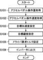
次に、図6を参照して、本実施形態によるトルク制御処理について説明する。図6は、本実施形態によるトルク制御処理を示すフローチャートである。このフローは、車両1の電源がONにされるとPCM14によって開始され、所定の周期で繰り返し実行される。<Control processing>
Next, referring to FIG. 6, torque control processing according to the present embodiment will be described. FIG. 6 is a flowchart showing torque control processing according to this embodiment. This flow is started by the
まず、ステップS101において、PCM14は、アクセルペダルセンサ16が検出したアクセルペダル操作量を取得する。このとき、PCM14は、車速センサ18が検出した車速を取得してもよい。 First, in step S<b>101 , the
次に、ステップS102において、PCM14は、ステップS101において取得したアクセルペダル操作量を時間微分することによりアクセルペダル操作速度を取得する。 Next, in step S102, the
次に、ステップS103において、PCM14は、ステップS101において取得したアクセルペダル操作量に基づき、目標加速度を設定する。例えば、目標加速度は、アクセルペダルの操作量が所定値(例えば20%)未満では負値、所定値のときに0[m/s2]、所定値より大きいときに正値となり、アクセルペダルの操作量が大きいほど(つまりアクセルペダルを踏み込むほど)目標加速度が大きくなるように設定される。さらに、PCM14は、ステップS101において車速を取得した場合、車速が低いときには車速が高いときよりも目標加速度が大きくなるように、目標加速度を設定してもよい。Next, in step S103, the
次に、ステップS104において、PCM14は、ステップS103において設定した目標加速度と、ステップS102において取得したアクセルペダル操作速度とに基づき、目標躍度を設定する。アクセルペダルが踏み込まれている場合、PCM14は、図4に例示したようなマップに基づき、目標加速度とアクセルペダル操作速度とに応じた目標躍度を設定する。また、アクセルペダルが踏み戻されている場合には、PCM14は、図5に例示したようなマップに基づき、目標加速度とアクセルペダル操作速度とに応じた目標躍度を設定する。 Next, in step S104, the
次に、ステップS105において、PCM14は、ステップS103において設定した目標加速度と、ステップS104において設定した目標躍度とに基づき、ドライバ要求トルクを設定する。例えば、PCM14は、車両1を目標加速度で加速又は減速させるためにモータ2が発生すべきトルクを算出する。そしてPCM14は、算出したトルクまでドライバ要求トルクを変化させるときに、車両1の加速度の変化率が目標躍度となるように、ドライバ要求トルクの変化率を決定する。この変化率と前回の命令実行サイクルにおけるドライバ要求トルクとに基づき、PCM14は、今回の命令実行サイクルにおけるドライバ要求トルクを設定する。 Next, in step S105, the
次に、ステップS106において、PCM14は、ステップS105において設定したドライバ要求トルクをインバータ12に出力する。これにより、インバータ12は、PCM14から入力されたドライバ要求トルクに基づき、モータ2に流れる電流を制御する。ステップS106の後、PCM14は、今回の命令実行サイクルにおけるトルク制御処理を終了する。 Next, in step S106, the
<変形例>
次に、本発明の実施形態の変形例を説明する。上述した実施形態では、車両1が、車両1を駆動又は制動するトルクを発生する動力源としてモータ2を搭載する場合を例として説明したが、モータ2と共に、あるいはモータ2に代えて、動力源としてガソリンエンジンやディーゼルエンジンなど内燃機関を搭載してもよい。この場合、PCM14は、図6のステップS105において設定したドライバ要求トルクに基づき、ステップS106において内燃機関のスロットルバルブや燃料噴射弁、可変動弁機構等を制御する。<Modification>
Next, modifications of the embodiment of the present invention will be described. In the above-described embodiment, the
<作用効果>
次に、上述した実施形態及び別実施形態による車両の制御装置の作用効果について説明する。<Effect>
Next, the effects of the vehicle control device according to the above-described embodiment and another embodiment will be described.
まず、PCM14は、目標加速度が0より小さい値から0に向かって増加している場合、目標加速度が0に近づくほど目標躍度が小さくなるように、目標躍度を設定し、目標加速度と目標躍度とに基づき、動力源が出力又は回生するトルクを設定する。
したがって、車両1の目標加速度が負値から0に近づくにつれて車両1の加速度の変化度合が小さくなるので、減速中にドライバがアクセルペダルを急激に踏み込んだ場合でも、車両1のピッチ方向の姿勢が前傾から水平に近づくほど姿勢変化を穏やかにすることができる。これにより、車両1のピッチ方向の姿勢が水平を跨ぐときに乗員の首に加わる力の急激な変化を抑制し、快適性を維持することができる。First, when the target acceleration increases from a value smaller than 0 to 0, the
Therefore, as the target acceleration of the
また、PCM14は、目標加速度が0より小さい値から0に向かって増加している場合の目標加速度の変化に応じた目標躍度の変化度合よりも、目標加速度が0以上の値から増加している場合の目標加速度の変化に応じた目標躍度の変化度合の方が小さくなるように、目標躍度を設定する。
したがって、車両1の目標加速度が負値から増加し0を跨いだ後の車両1の加速度の変化度合が小さくなるので、減速中にドライバがアクセルペダルを急激に踏み込んだ場合でも、車両1のピッチ方向の姿勢が前傾から水平を跨いで後傾に切り替わった後の姿勢変化をより穏やかにすることができる。In addition, the
Therefore, the degree of change in the acceleration of the
また、PCM14は、アクセルペダル操作量が増加している場合、アクセルペダル操作速度が大きい程、目標躍度が大きくなるように、目標躍度を設定する。
したがって、ドライバがアクセルペダルを急激に踏み込むほど加速度の変化度合を大きくすることができ、アクセルペダルを操作するドライバの意図を反映することができる。Further, the
Therefore, the more abruptly the driver depresses the accelerator pedal, the greater the degree of change in acceleration can be, and the intention of the driver operating the accelerator pedal can be reflected.
また、PCM14は、目標加速度が0より小さい値から0に向かって増加している場合において、アクセルペダル操作速度が所定値以上である場合に、目標加速度が0に近づくほど目標躍度が小さくなるように、目標躍度を設定する。
したがって、減速中にドライバがアクセルペダルを所定以上に急激に踏み込んだ場合に、車両1の目標加速度が負値から0に近づくにつれて車両1の加速度の変化度合が小さくなるので、車両1のピッチ方向の姿勢が前傾から水平に近づくほど姿勢変化を穏やかにすることができる。これにより、急激なアクセルペダルの操作に応じて車両1のピッチ方向の姿勢が水平を跨ぐときに、乗員の首に加わる力の急激な変化を確実に抑制できる。Further, when the target acceleration increases from a value smaller than 0 toward 0, the
Therefore, when the driver depresses the accelerator pedal abruptly beyond a predetermined value during deceleration, the degree of change in the acceleration of the
また、PCM14は、目標加速度が0より大きい値から0に向かって減少している場合、目標加速度が0に近づくほど目標躍度の絶対値が小さくなるように、目標躍度を設定する。
したがって、車両1の目標加速度が正値から0に近づくにつれて車両1の加速度の変化度合が小さくなるので、加速中にドライバがアクセルペダルを急激に踏み戻した場合でも、車両1のピッチ方向の姿勢が後傾から水平に近づくほど姿勢変化を穏やかにすることができる。これにより、車両1のピッチ方向の姿勢が水平を跨ぐときに乗員の首に加わる力の急激な変化を抑制し、快適性を維持することができる。Further, when the target acceleration decreases from a value greater than 0 to 0, the
Therefore, as the target acceleration of the
また、PCM14は、目標加速度が0以上の値から増加している場合、目標加速度が大きくなるほど目標躍度が大きくなるように、目標躍度を設定する。
したがって、アクセルペダルの踏み込みに応じて目標加速度が大きくなる程、車両1の加速度の増加度合が大きくなるので、伸びのある加速感を実現することができる。Further, when the target acceleration increases from a value of 0 or more, the
Therefore, as the target acceleration increases in response to depression of the accelerator pedal, the degree of increase in the acceleration of the
また、PCM14は、目標加速度が0より大きい値から0に向かって減少している場合の目標加速度の変化に応じた目標躍度の変化度合よりも、目標加速度が0以下の値から減少している場合の目標加速度の変化に応じた目標躍度の変化度合の方が小さくなるように、目標躍度を設定する。
したがって、車両1の目標加速度が正値から減少し0を跨いだ後の車両1の加速度の変化度合が小さくなるので、加速中にアクセルペダルを急激に踏み戻した場合でも、車両1のピッチ方向の姿勢が後傾から水平を跨いで前傾に切り替わった後の姿勢変化をより穏やかにすることができる。In addition, the
Therefore, the degree of change in the acceleration of the
また、PCM14は、アクセルペダル操作量が減少している場合、アクセルペダル操作速度の絶対値が大きい程、目標躍度の絶対値が大きくなるように、目標躍度を設定する。
したがって、ドライバがアクセルペダルを急激に踏み戻すほど加速度の変化度合を大きくすることができ、アクセルペダルを操作するドライバの意図を反映することができる。Further, the
Therefore, the more abruptly the driver depresses the accelerator pedal, the greater the degree of change in acceleration, thereby reflecting the intention of the driver operating the accelerator pedal.
また、PCM14は、目標加速度が0以下の値から減少している場合、目標加速度の絶対値が大きくなるほど目標躍度の絶対値が小さくなるように、目標躍度を設定する。
したがって、アクセルペダルの踏み戻しに応じて目標加速度の絶対値(即ち目標減速度)が大きくなる程、車両1の加速度の絶対値の増加度合(即ち減速度の増加度合)が小さくなるので、急ブレーキ感を和らげることができる。Further, when the target acceleration is decreasing from a value of 0 or less, the
Therefore, as the absolute value of the target acceleration (that is, the target deceleration) increases in accordance with the release of the accelerator pedal, the degree of increase in the absolute value of the acceleration of the vehicle 1 (that is, the degree of increase in deceleration) decreases. It can soften the feeling of braking.
また、動力源は電気モータなので、設定された目標加速度及び目標躍度に応じて車両1を駆動又は制動するトルクを精度よく制御することができる。 Further, since the power source is an electric motor, the torque for driving or braking the
1 車両
2 モータ
4 減速機
6 ドライブシャフト
8 駆動輪
10 バッテリ
12 インバータ
14 PCM
16 アクセルペダルセンサ
18 車速センサ
20 プロセッサ
22 メモリREFERENCE SIGNS
16
Claims (5)
Translated fromJapaneseアクセルペダルの操作量を検出するアクセルペダルセンサと、
前記動力源を制御する制御ユニットと、
を備える車両の制御装置であって、
前記制御ユニットは、
前記アクセルペダルセンサにより検出されたアクセルペダル操作量に基づき目標加速度を設定し、
前記目標加速度に基づき目標躍度を設定し、
前記目標加速度が0より大きい値から0に向かって減少している場合、前記目標加速度が0に近づくほど前記目標躍度の絶対値が小さくなるように、前記目標躍度を設定し、
前記目標加速度と前記目標躍度とに基づき、前記動力源が出力又は回生するトルクを設定するように構成されている、
車両の制御装置。a power source that generates torque to drive or brake the vehicle;
an accelerator pedal sensor that detects the amount of operation of the accelerator pedal;
a control unit that controls the power source;
A control device for a vehicle comprising
The control unit is
setting a target acceleration based on the accelerator pedal operation amount detected by the accelerator pedal sensor;
setting a target jerk based on the target acceleration;
setting the target jerk such that when the target acceleration decreases from a value greater than 0 toward 0, the absolute value of the target jerk decreases as the target acceleration approaches 0;
configured to set the torque output or regenerated by the power source based on the target acceleration and the target jerk;
Vehicle controller.
前記アクセルペダル操作量に基づきアクセルペダル操作速度を取得し、
前記アクセルペダル操作量が減少している場合、前記アクセルペダル操作速度の絶対値が大きい程、前記目標躍度の絶対値が大きくなるように、前記目標躍度を設定するように構成されている、請求項1又は2に記載の車両の制御装置。The control unit is
acquiring an accelerator pedal operation speed based on the accelerator pedal operation amount;
The target jerk is set such that the absolute value of the target jerk increases as the absolute value of the accelerator pedal operation speed increases when the accelerator pedal operation amount is decreasing. 3. A control device for a vehicle according to claim 1 or 2.
Priority Applications (2)
| Application Number | Priority Date | Filing Date | Title |
|---|---|---|---|
| JP2021156609AJP2023047610A (en) | 2021-09-27 | 2021-09-27 | Control device for vehicle |
| US17/900,732US20230098578A1 (en) | 2021-09-27 | 2022-08-31 | Vehicle control device |
Applications Claiming Priority (1)
| Application Number | Priority Date | Filing Date | Title |
|---|---|---|---|
| JP2021156609AJP2023047610A (en) | 2021-09-27 | 2021-09-27 | Control device for vehicle |
Publications (1)
| Publication Number | Publication Date |
|---|---|
| JP2023047610Atrue JP2023047610A (en) | 2023-04-06 |
Family
ID=85718563
Family Applications (1)
| Application Number | Title | Priority Date | Filing Date |
|---|---|---|---|
| JP2021156609APendingJP2023047610A (en) | 2021-09-27 | 2021-09-27 | Control device for vehicle |
Country Status (2)
| Country | Link |
|---|---|
| US (1) | US20230098578A1 (en) |
| JP (1) | JP2023047610A (en) |
Families Citing this family (1)
| Publication number | Priority date | Publication date | Assignee | Title |
|---|---|---|---|---|
| JP2023047609A (en)* | 2021-09-27 | 2023-04-06 | マツダ株式会社 | Control device for vehicle |
Citations (7)
| Publication number | Priority date | Publication date | Assignee | Title |
|---|---|---|---|---|
| JP2006132463A (en)* | 2004-11-08 | 2006-05-25 | Toyota Motor Corp | Vehicle control device |
| JP2006175943A (en)* | 2004-12-21 | 2006-07-06 | Toyota Motor Corp | Acceleration / deceleration controller |
| JP2009057874A (en)* | 2007-08-30 | 2009-03-19 | Toyota Motor Corp | Driving force control device |
| WO2012153367A1 (en)* | 2011-05-11 | 2012-11-15 | 日立オートモティブシステムズ株式会社 | Vehicle operation control device and vehicle operation control system |
| US20160221466A1 (en)* | 2013-09-10 | 2016-08-04 | Chong-Chul Kim | Method and device for sensory control of hybrid operation machine |
| JP2016160864A (en)* | 2015-03-03 | 2016-09-05 | マツダ株式会社 | Control device for engine |
| JP2021142780A (en)* | 2020-03-10 | 2021-09-24 | トヨタ自動車株式会社 | Vehicular brake-drive force control apparatus |
Family Cites Families (6)
| Publication number | Priority date | Publication date | Assignee | Title |
|---|---|---|---|---|
| US8744689B2 (en)* | 2007-07-26 | 2014-06-03 | Hitachi, Ltd. | Drive controlling apparatus for a vehicle |
| JP2011148342A (en)* | 2010-01-19 | 2011-08-04 | Toyota Motor Corp | Vehicle control device |
| JP6645471B2 (en)* | 2017-04-18 | 2020-02-14 | トヨタ自動車株式会社 | Vehicle driving force control device |
| RU2723010C1 (en)* | 2017-07-03 | 2020-06-08 | Ниссан Мотор Ко., Лтд. | Method for generating target vehicle speed and device for generating target vehicle speed for vehicle with driving assistance |
| JP7198829B2 (en)* | 2018-09-27 | 2023-01-04 | 日立Astemo株式会社 | vehicle controller |
| JP7052679B2 (en)* | 2018-11-07 | 2022-04-12 | トヨタ自動車株式会社 | Vehicle driving force control device |
- 2021
- 2021-09-27JPJP2021156609Apatent/JP2023047610A/enactivePending
- 2022
- 2022-08-31USUS17/900,732patent/US20230098578A1/enactivePending
Patent Citations (7)
| Publication number | Priority date | Publication date | Assignee | Title |
|---|---|---|---|---|
| JP2006132463A (en)* | 2004-11-08 | 2006-05-25 | Toyota Motor Corp | Vehicle control device |
| JP2006175943A (en)* | 2004-12-21 | 2006-07-06 | Toyota Motor Corp | Acceleration / deceleration controller |
| JP2009057874A (en)* | 2007-08-30 | 2009-03-19 | Toyota Motor Corp | Driving force control device |
| WO2012153367A1 (en)* | 2011-05-11 | 2012-11-15 | 日立オートモティブシステムズ株式会社 | Vehicle operation control device and vehicle operation control system |
| US20160221466A1 (en)* | 2013-09-10 | 2016-08-04 | Chong-Chul Kim | Method and device for sensory control of hybrid operation machine |
| JP2016160864A (en)* | 2015-03-03 | 2016-09-05 | マツダ株式会社 | Control device for engine |
| JP2021142780A (en)* | 2020-03-10 | 2021-09-24 | トヨタ自動車株式会社 | Vehicular brake-drive force control apparatus |
Also Published As
| Publication number | Publication date |
|---|---|
| US20230098578A1 (en) | 2023-03-30 |
Similar Documents
| Publication | Publication Date | Title |
|---|---|---|
| JP7139875B2 (en) | vehicle controller | |
| JP6991466B2 (en) | Vehicle control system and method | |
| JP6985645B2 (en) | Vehicle control method, vehicle system and vehicle control device | |
| CN111433093B (en) | Control device for vehicle | |
| JP2022014672A (en) | Vehicle drive system | |
| JP6252992B2 (en) | Vehicle behavior control device | |
| JP2021102383A (en) | Vehicle control system | |
| JP2023047610A (en) | Control device for vehicle | |
| JP2010241245A (en) | Vehicle driving force control device | |
| JP7008944B2 (en) | Vehicle system | |
| JP6582697B2 (en) | Control system | |
| JP2020100349A (en) | Vehicle control device | |
| JP2008030678A (en) | Vehicle travel control device | |
| US11987244B2 (en) | Vehicle control method and vehicle control device | |
| JP2023047609A (en) | Control device for vehicle | |
| JP7034437B2 (en) | Vehicle control method and vehicle system | |
| JP7034438B2 (en) | Vehicle control method and vehicle system | |
| JP7310775B2 (en) | vehicle controller | |
| JP7100288B2 (en) | Vehicle control method and vehicle system | |
| JP2018165530A (en) | Vehicle control device | |
| JP2022131152A (en) | Vehicle driving force control device | |
| JP6536663B2 (en) | Vehicle control device | |
| JP2023121041A (en) | Driving force control device | |
| JP2020040480A (en) | Control method for vehicle, vehicle system and control device for vehicle | |
| JP6521493B1 (en) | Vehicle control device |
Legal Events
| Date | Code | Title | Description |
|---|---|---|---|
| A80 | Written request to apply exceptions to lack of novelty of invention | Free format text:JAPANESE INTERMEDIATE CODE: A80 Effective date:20210927 | |
| A621 | Written request for application examination | Free format text:JAPANESE INTERMEDIATE CODE: A621 Effective date:20240723 | |
| A977 | Report on retrieval | Free format text:JAPANESE INTERMEDIATE CODE: A971007 Effective date:20250528 | |
| A131 | Notification of reasons for refusal | Free format text:JAPANESE INTERMEDIATE CODE: A131 Effective date:20250626 | |
| A521 | Request for written amendment filed | Free format text:JAPANESE INTERMEDIATE CODE: A523 Effective date:20250820 |